CalAmp Wireless Networks 5016-500 Guardian 100 Wireless Radio Modem User Manual 1
CalAmp Wireless Networks Corporation Guardian 100 Wireless Radio Modem 1
Manual

Guardian-100™
Guardian-200™
Guardian-400™
Guardian-900™
Narrowband IP Router
User Manual
PN 001-5008-000 Rev 8E Preliminary ETSI Version
Revised May 27, 2010

REVISION HISTORY
REV
DATE
REVISION DETAILS
0
Dec 11, 2010
Initial Release as 001-5006-000.
IMPORTANT NOTICE
Because of the nature of wireless communication, transmission and reception of data can never
be guaranteed. Data may be delayed, corrupted (i.e., have errors), or be totally lost. Significant
delays or losses of data are rare when wireless devices such as the Guardian are used in a
normal manner with a well-constructed network. Guardian should not be used in situations
where failure to transmit or receive data could result in damage of any kind to the user or any
other party, including but not limited to personal injury, death, or loss of property. CalAmp
accepts no responsibility for damages of any kind resulting from delays or errors in data
transmitted or received using Guardian, or for the failure of Guardian to transmit or receive
such data.
COPYRIGHT NOTICE
© Copyright 2007 CalAmp.
Products offered may contain software proprietary to CalAmp. The offer of supply of these
products and services does not include or infer any transfer of ownership. No part of the
documentation or information supplied may be divulged to any third party without the express
written consent of CalAmp.
RF EXPOSURE COMPLIANCE REQUIREMENTS
The Guardian radio is intended for use in the Industrial Monitoring and Control
and SCADA markets. The Guardian unit must be professionally installed and must ensure a
minimum separation distance listed in the table below between the radiating structure and any
person. An antenna mounted on a pole or tower is the typical installation and in rare instances,
a 1/2-wave whip antenna is used.
Antenna Gain
5 dBi
10 dBi
15 dBi
Min Safety Distance
(VHF @ max Power)
123cm
218.8cm
389cm
Min Safety Distance
(UHF @ max Power)
105.7cm
188cm
334.4cm
Min Safety Distance
(900 MHz @ max power)
63.8cm
115 cm
201.7 cm
Note: It is the responsibility of the user to guarantee compliance with the FCC MPE
regulations when operating this device in a way other than described above.
The Guardian radio uses a low power radio frequency transmitter. The concentrated energy
from an antenna may pose a health hazard. People should not be in front of the antenna when
the transmitter is operating.
The installer of this equipment must ensure the antenna is located or pointed such that it does
not emit an RF field in excess of Health Canada limits for the general population. Recommended
safety guidelines for the human exposure to radio frequency electromagnetic energy are
contained in the Canadian Safety Code 6 (available from Health Canada) and the Federal
Communications Commission (FCC) Bulletin 65.
RF Exposure

Any changes or modifications not expressly approved by the party responsible for compliance
(in the country where used) could void the user's authority to operate the equipment.
REGULATORY CERTIFICATIONS
The Guardian radio is available in several different models each with unique frequency bands.
Each model of Guardian may have different regulatory approval as shown in the table below.
UL Certification
All models
UL approved when powered with a listed Class 2 source.
DECLARATION OF CONFORMITY FOR MODEL # 140-5046-400
This device (Guardian model #140-5046-400) is a data transceiver intended for commercial
and industrial use in all EU and EFTA member states.
Česky [Czech]
CalAmp tímto prohlašuje, že tento rádio je ve shodě se základními
požadavky a dalšími příslušnými ustanoveními směrnice 1999/5/ES.
Dansk [Danish]
Undertegnede CalAmp erklærer herved, at følgende udstyr radio
overholder de væsentlige krav og øvrige relevante krav i direktiv
1999/5/EF.
Deutsch [German]
Hiermit erklärt CalAmp, dass sich das Gerät radio in Übereinstimmung
mit den grundlegenden Anforderungen und den übrigen einschlägigen
Bestimmungen der Richtlinie 1999/5/EG befindet.
Eesti [Estonian]
Käesolevaga kinnitab CalAmp seadme raadio vastavust direktiivi
1999/5/EÜ põhinõuetele ja nimetatud direktiivist tulenevatele teistele
asjakohastele sätetele.
English
Hereby, CalAmp, declares that this radio is in compliance with the
essential requirements and other relevant provisions of Directive
1999/5/EC.
Español [Spanish]
Por medio de la presente CalAmp declara que el radio cumple con los
requisitos esenciales y cualesquiera otras disposiciones aplicables o
exigibles de la Directiva 1999/5/CE.
Ελληνική [Greek]
ΜΕ ΣΗΝ ΠΑΡΟΤΑ CalAmp ΔΗΛΩΝΕΙ ΟΣΙ ΡΑΔΙΌΦΩΝΟ
ΤΜΜΟΡΦΩΝΕΣΑΙ ΠΡΟ ΣΙ ΟΤΙΩΔΕΙ ΑΠΑΙΣΗΕΙ ΚΑΙ ΣΙ ΛΟΙΠΕ
ΥΕΣΙΚΕ ΔΙΑΣΑΞΕΙ ΣΗ ΟΔΗΓΙΑ 1999/5/ΕΚ.
Français [French]
Par la présente CalAmp déclare que l'appareil radio est conforme aux
exigences essentielles et aux autres dispositions pertinentes de la
directive 1999/5/CE.
Italiano [Italian]
Con la presente CalAmp dichiara che questo radio è conforme ai
requisiti essenziali ed alle altre disposizioni pertinenti stabilite dalla
Certifications
Model Number
Frequency Range
FCC
IC (DOC)
European Union
EN 300 113
Australia/New
Zealand
140-5016-500
136 – 174 MHz
NP4-5016-500
773B-5016500
140-5016-501
136 – 174 MHz
NP4-5016-500
773B-5016500
140-5026-500
216 – 222 MHz
NP4-5026-500
773B-5026500
140-5026-501
216 – 222 MHz
NP4-5026-500
773B-5026500
140-5046-300
406 - 470 MHz
NP4-5046-500
773B-5046500
140-5046-301
406 - 470 MHz
NP4-5046-500
773B-5046500
140-5046-500
450 - 512 MHz
NP4-5046-500
773B-5046500
140-5046-501
450 - 512 MHz
NP4-5046-500
773B-5046500
140-5096-500
928 - 960 MHz
NP4-5096-500
773B-5096500
140-5096-501
928 - 960 MHz
NP4-5096-500
773B-5096500

direttiva 1999/5/CE.
Latviski [Latvian]
Ar šo CalAmp deklarē, ka radio atbilst Direktīvas 1999/5/EK būtiskajām
prasībām un citiem ar to saistītajiem noteikumiem.
Lietuvių [Lithuanian]
Šiuo CalAmp deklaruoja, kad šis radijo atitinka esminius reikalavimus ir
kitas 1999/5/EB Direktyvos nuostatas.
Nederlands [Dutch]
Hierbij verklaart CalAmp dat het toestel radio in overeenstemming is
met de essentiële eisen en de andere relevante bepalingen van richtlijn
1999/5/EG.
Malti [Maltese]
Hawnhekk, CalAmp , jiddikjara li dan tar-radju jikkonforma mal-ħtiġijiet
essenzjali u ma provvedimenti oħrajn relevanti li hemm fid-Dirrettiva
1999/5/EC.
Magyar [Hungarian]
Alulírott, CalAmp nyilatkozom, hogy a rádió megfelel a vonatkozó
alapvetõ követelményeknek és az 1999/5/EC irányelv egyéb
elõírásainak.
Polski [Polish]
Niniejszym CalAmp oświadcza, że radio jest zgodny z zasadniczymi
wymogami oraz pozostałymi stosownymi postanowieniami Dyrektywy
1999/5/EC.
Português
[Portuguese]
CalAmp declara que este rádio está conforme com os requisitos
essenciais e outras disposições da Directiva 1999/5/CE.
Slovensko
[Slovenian]
CalAmp izjavlja, da je ta radio v skladu z bistvenimi zahtevami in
ostalimi relevantnimi določili direktive 1999/5/ES.
Slovensky [Slovak]
CalAmp týmto vyhlasuje, že rádio spĺňa základné požiadavky a všetky
príslušné ustanovenia Smernice 1999/5/ES.
Suomi [Finnish]
CalAmp vakuuttaa täten että radio tyyppinen laite on direktiivin
1999/5/EY oleellisten vaatimusten ja sitä koskevien direktiivin muiden
ehtojen mukainen.
Svenska [Swedish]
Härmed intygar CalAmp att denna radio står I överensstämmelse med
de väsentliga egenskapskrav och övriga relevanta bestämmelser som
framgår av direktiv 1999/5/EG.
Íslenska [Icelandic]
Hér með lýsir CalAmp yfir því að útvarp er í samræmi við grunnkröfur
og aðrar kröfur, sem gerðar eru í tilskipun 1999/5/EC.
Norsk [Norwegian]
CalAmp erklærer herved at utstyret radio er i samsvar med de
grunnleggende krav og øvrige relevante krav i direktiv 1999/5/EF.

TABLE OF CONTENTS
1 GUARDIAN OVERVIEW ........................................................................................................................................... 9
1.1 General Description ............................................................................................................................................ 9
1.2 Operational Characteristics ............................................................................................................................... 9
1.3 Physical Description ......................................................................................................................................... 10
1.3.1 Front PanelThe front panel has the following connections: ........................................................................ 10
1.3.1 The front panel has the following connections: .......................................................................................... 11
1.3.2 LED Panel ................................................................................................................................................... 11
1.3.3 User Interface Port ...................................................................................................................................... 11
1.3.4 SETUP and COM Ports .............................................................................................................................. 12
1.3.5 Power Connector ........................................................................................................................................ 12
1.3.6 Antenna Connector ..................................................................................................................................... 13
1.3.7 Chassis Dimensions .................................................................................................................................... 13
1.4 Part Numbers and Availability ........................................................................................................................ 14
1.4.1 Guardian Radio ........................................................................................................................................... 14
1.4.2 Accessories and Options ............................................................................................................................. 14
1.5 Product Warranty ............................................................................................................................................ 15
1.6 RMA Request .................................................................................................................................................... 16
1.7 Documentation and Downloads ....................................................................................................................... 16
2 SYSTEM ARCHITECTURE AND NETWORK PLANNING ................................................................................. 17
2.1 Single Coverage Area ....................................................................................................................................... 17
2.2 Network Architecture ....................................................................................................................................... 17
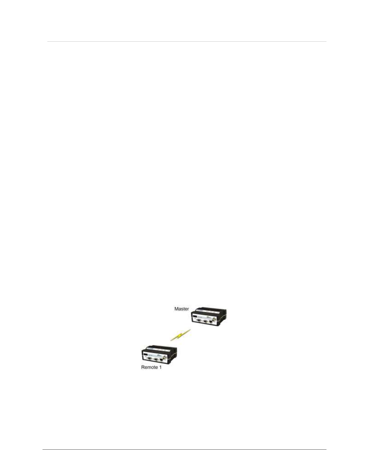
2.2.1 Point-to-Point .............................................................................................................................................. 17
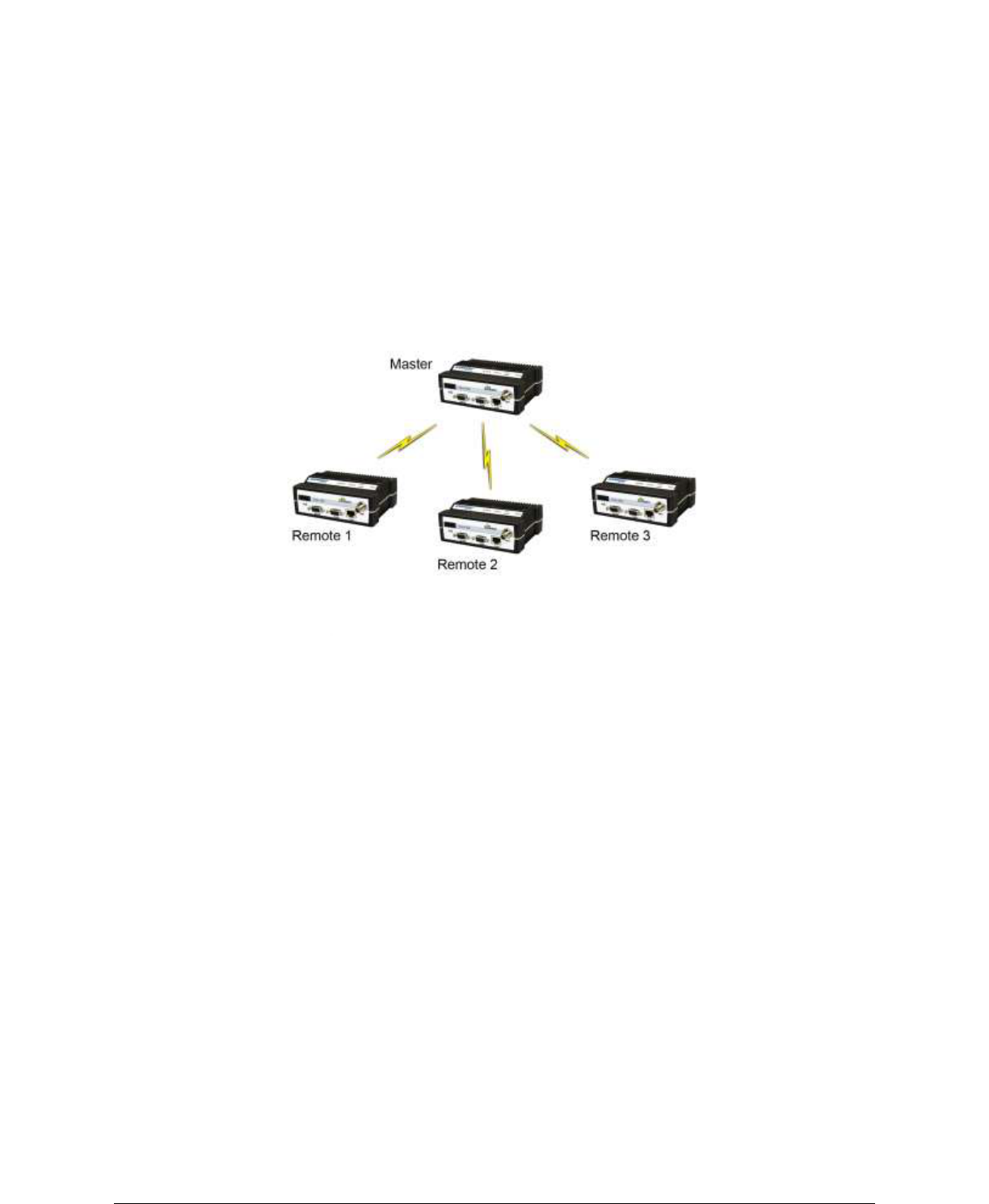
2.2.2 Point-to-Multipoint ..................................................................................................................................... 18
2.2.3 Multiple Point-to-Point ............................................................................................................................... 18
2.2.4 Peer-to-Peer ................................................................................................................................................ 18
2.2.5 Store and Forward ....................................................................................................................................... 18
2.2.6 Network Using a T-Base ............................................................................................................................. 18
2.2.7 NETWORK USING A T-BASE REPEATER ........................................................................................... 19
2.2.8 NETWORK USING A GUARDIAN FOR ONLINE DIAGNOSTICS ..................................................... 19
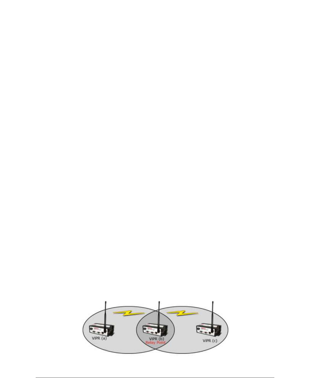
2.3 Extending the Coverage Area with a Relay Point .......................................................................................... 19
2.3.1 Understanding RF Path Requirements ........................................................................................................ 20
2.4 Site Selection and Site Survey .......................................................................................................................... 20
2.4.1 Site Selection .............................................................................................................................................. 20
2.4.2 Site Survey .................................................................................................................................................. 21
2.5 Selecting Antenna and Feedline ....................................................................................................................... 21
2.5.1 Antenna Gain .............................................................................................................................................. 21
2.5.2 Omni Directional Antenna .......................................................................................................................... 21
2.5.3 Yagi Antenna .............................................................................................................................................. 22
2.5.4 Vertical Dipoles .......................................................................................................................................... 22
2.5.5 Feedline ...................................................................................................................................................... 22
2.5.6 RF Exposure Compliance Requirements .................................................................................................... 22
2.6 Terrain and Signal Strength ............................................................................................................................ 23
2.7 Radio Interference ............................................................................................................................................ 24
3 Setup and Configuration ........................................................................................................................................... 25
3.1 Install the Antenna ........................................................................................................................................... 25
3.2 Measure and Connect Primary Power ............................................................................................................ 25
3.3 Connect Guardian to Programming PC ......................................................................................................... 25

3.4 GUARDIAN FIELD PROGRAMMING SOFTWARE ................................................................................ 25
4 UNIT STATUS........................................................................................................................................................... 26
4.1 Unit Identification and Status .......................................................................................................................... 26
4.2 Diagnostics ......................................................................................................................................................... 26
4.2.1 Online Diagnostics ...................................................................................................................................... 26
4.2.2 Offline Diagnostics ..................................................................................................................................... 26
4.2.3 Remote Commands ..................................................................................................................................... 27
5 Using Guardian Software .......................................................................................................................................... 28
GUARDIAN SPECIFICATIONS ..................................................................................................................................... 52
PRODUCT WARRANTY .................................................................................................................................................. 58
6 PRODUCT WARRANTY .......................................................................................................................................... 58

001-5006-000_FCC.docx Page 9
1 GUARDIAN OVERVIEW
This document provides information required for the operation and verification of the
CalAmp Guardian Narrowband Modem.
1.1 GENERAL DESCRIPTION
This DSP-based radio was designed for SCADA, telemetry and industrial applications in the
136-174 MHz, 215-240 MHz VHF, 406.1-512 MHz UHF, and 928-960 MHz frequency ranges.
Guardian supports serial Remote Terminal Units (RTU) and programmable logic controllers
(PLC). The Guardian is compatible with any Dataradio Interoperability Standard (DI-OS)
equipment and Bell 202/212 interface.
1.2 OPERATIONAL CHARACTERISTICS
The Guardian product has the following operational characteristics:
Frequency range of 136-174 MHz, 215-240 MHz, 406.1-470 MHz, 450-512 MHz, or
928-960 MHz.
User-selectable data rates
Built-in transceiver adjustable from 1 to 10 watts (8 watts max for 900MHz)
Wide input power range of 10 to 30 volts DC
Online and Offline Diagnostics
Supports up to 8 different frequency channel pairs (selectable through user interface
port).
Industrial operating temperature range of -30 to +60 C
Rugged die-cast aluminum and steel case

001-5006-000_FCC.docx Page 10
These features provide system benefits that give users:
Rugged Packaging. Guardian is housed in a compact and rugged cast aluminum case.
Built for industrial applications in a variety of environments, Guardian operates over an
extended temperature range and provides worry-free operation in the roughest
environments.
Simple Installation. Basic installation typically utilizes an omni-directional antenna at the
master station or Relay Point and a directional antenna at each remote site not a Relay
Point. See Section 2 for information on Site and Antenna Selection. For basic service, just
hook up an antenna, apply primary power, check and set a few operating parameters and
you are done.
Flexible Management. Configuration, commissioning, maintenance and troubleshooting
can be done locally or remotely. There are no physical switches or adjustments. The Dual-
Port Guardian provides a receive antenna connector allowing for unique customer
applications requiring additional receive filtering, external PA(s), and other options.
Long Range. Narrowband configurations allow better coverage over harsh terrain.
1.3 PHYSICAL DESCRIPTION
Guardian consists of two logic PCBs, one that includes the modem circuitry and the other
the radio module. Both are installed in a cast aluminum case. The unit is not hermetically
sealed and should be mounted in a suitable enclosure when dust, moisture, and/or a
corrosive atmosphere are anticipated.
The Guardian is designed for easy installation and configuration; the Guardian features no
external or internal switches or adjustments. All operating parameters are set via the setup
port.
1.3.1 Front Panel

001-5006-000_FCC.docx Page 11
The front panel has the following connections:
(1) 8-Pin user interface block connector
(1) 50-ohm TNC female Antenna connector
(1) 50-ohm SMA female receive antenna connector (Dual-Port models only)
(1) Right-angle power connector (10-30 VDC)
(2) DE-9F RS-232 ports
For Dual-port Guardian connections, see Section 1.3.6.
1.3.2 LED Panel
The LED panel has five Tri-Color LEDs. The functionality of each LED is shown in Table 1.1.
Table 1.1 Guardian LED Functionality
LED
Color
Definition
Power
Green
Amber (Solid or Blinking)
Red
Guardian ready, normal operations
Guardian is Programing
Guardian hardware fault
Status
Green
Red
Amber (Solid or Blinking)
Guardian no faults, normal operations
Guardian has a fault condition, check unit status
Guardian detects high background noise
Rx
Green
Off
Receiving data
Tx
Red
Blinking Amber
Off
Transmitting data
The unit wants to transmit, but is inhibited.
Rd/Td
Green
Red
Receive data is being sent out of the port
Transmit data is being received by the port
1.3.3 User Interface Port
The user interface port is an 8 pin block receptacle, programmable to work with 1.8V to 5V
levels. Table 1.2 shows pin-out descriptions for the RJ-45 port.
Table 1.2 Pin-out for User Interface Port Contacts
Contact
10 Base-T Signal
1
Tx Audio In
2
Rx Audio Out
3
PTT
4
RSSI Out
5
Ground
6
Channel Select 1
7
Channel Select 2
8
Channel Select 3
001-5006-000_FCC.docx Page 12
1.3.4 SETUP and COM Ports
The SETUP and COM serial connections are DE-9F RS-232 ports.
Serial port considerations:
Guardian radio modem SETUP and COM ports are Data Communication Equipment
(DCE) devices
In general, equipment connected to the Guardian’s SETUP / COM serial port is Data
Terminal Equipment (DTE) and a straight-through cable is recommended.
Note: If a DCE device is connected to the Guardian SETUP / COM port, a null modem
cable/adapter is required.
The pin-out for the SETUP and COM ports are shown in Table 1.3.
Table 1.3 Pin-out for DCE SETUP and COM port, 9 Contact DE-9 Connector
Contact
EIA-232F Function
Signal Direction
1
DCD(1)
DTE ← DCE
2
RXD
DTE ← DCE
3
TXD
DTE → DCE
4
DTR
DTE → DCE
5
GND
DTE --- DCE
6
DSR(2)
DTE ← DCE
7
RTS(1)
DTE → DCE
8
CTS(1)
DTE ← DCE
9
RING (3)
DTE --- DCE
(1) Programmable.
(2) Always asserted
(3) For future use
The DCD, DTR, RTS and CTS control lines are programmable. Refer to section 6.4 for serial
port control line configurations.
1.3.5 Power Connector
The Guardian is supplied with a right-angle power connector (10-30 VDC). Table 1.4 shows
the pin-out of the power connector.
Table 1.4 Pin-out of the power connector
Contact #
(Left to Right)
Color
Description
4
Fan Power Output (5V)
3
Black
Ground
2
Red
Positive (10-30) VDC
1
White
Enable
Note: The White Enable line must be tied to the red positive lead of the connector for the
Guardian to function.
001-5006-000_FCC.docx Page 13
1.3.6 Antenna Connector
The standard Guardian has a 50-ohm TNC female antenna connector. This connection
functions for both transmit and receive.
The Dual-Port Guardian has a 50-ohm TNC female antenna connector functioning for
transmit (only) and a 50-ohm SMA female antenna connector functioning for receive (only).
The separate receive antenna connector allows for unique customer applications that require
additional receive filtering, external PA(s) and other options.
Warning: The transmit antenna port must not be connected directly to the receive
antenna port of the Dual-Port Guardian. Excessive power into the receive antenna
port will damage the radio. Input power to the receiver should not exceed 17 dBm
(50mW).
To reduce potential interference, the antenna type and its gain should be chosen to ensure
the effective isotropic radiated power (EIRP) is not more than required for successful
communication.
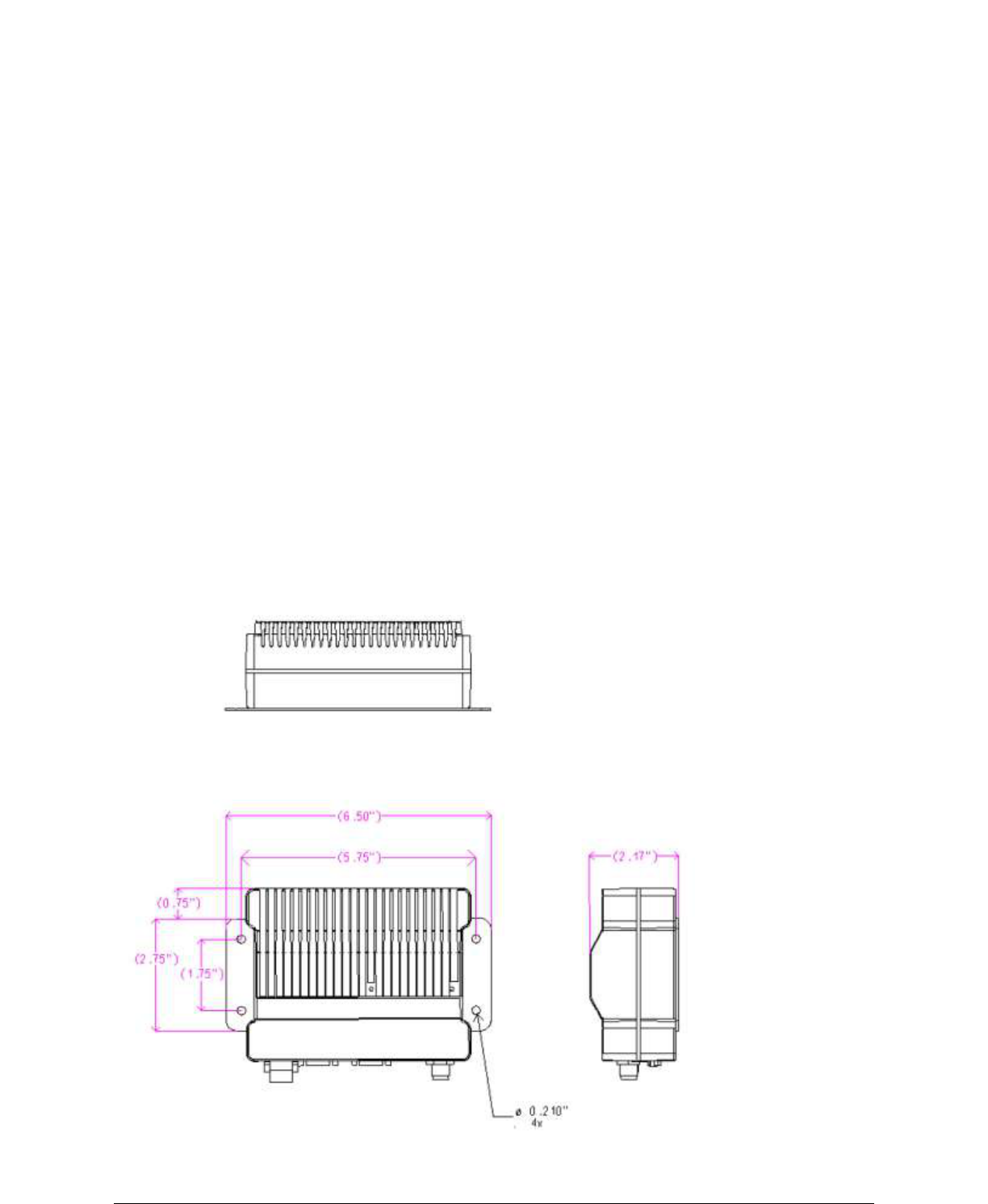
1.3.7 Chassis Dimensions
Figure 1.2 shows the dimensions of the Guardian Chassis and mounting plate.
Figure 1.2 Guardian Chassis Dimensions (units are in inches)

001-5006-000_FCC.docx Page 14
1.4 PART NUMBERS AND AVAILABILITY
1.4.1 Guardian Radio
Table 1.5 provides a breakdown of the Guardian part number 140-50X6-Y0Z.
Table 1.5 - Part Number Breakdown
Model Number
Description
Frequency Range
140-5016-500
Standard VHF Guardian
136 - 174 MHz
140-5026-502
Standard VHF Guardian-200
215 - 240 MHz
140-5046-300
Standard UHF Guardian Range 3
406.1 - 470 MHz
140-5046-500
Standard UHF Guardian Range 5
450 - 512 MHz
140-5096-500
Standard 900MHz Guardian
928 - 960 MHz
140-5016-501
Dual Port VHF Guardian
136 - 174 MHz
140-5026-503
Dual Port VHF Guardian-200
215 - 240 MHz
140-5046-301
Dual Port UHF Guardian Range 3
406.1 - 470 MHz
140-5046-501
Dual Port UHF Guardian Range 5
450 - 512 MHz
140-5096-501
Dual Port 900MHz Guardian
928 - 960 MHz
1.4.2 Accessories and Options
Tables 1.6-1.8 list standard accessories (including antenna, feedline, and connectors) tested
and approved for use with the Guardian.
Table 1.6 - Accessories
ITEM
PART NUMBER
Guardian Power Cable
897-5008-010
Guardian Demo Kit* – VHF - 136-174 MHz
250-5016-500
Guardian Demo Kit* – VHF 200 - 215-240 MHz
250-5026-502
Guardian Demo Kit* – UHF - 406-470 MHz
250-5046-300
Guardian Demo Kit* – UHF - 450-512 MHz
250-5046-500
Guardian Demo Kit* – 900 - 928-960 MHz
250-5096-500
Factory Installed Guardian Fan Kit
150-5008-001
Field Installed Guardian Fan Kit**
150-5008-002
TNC-Male to N-Male 18”
250-0697-103
TNC-Male to N-Male 48”
250-0697-104
TNC-Male to N-Male 72”
250-0697-105
TNC-Male to N-Female 18”
250-0697-106
* The Guardian Demo Kit includes two of each of the following: Guardian, rubber duck antennas, adapters,
attenuators, power cables, and power supplies.
** The field install Fan Kit is available for all VHF 200/UHF/900 Guardians (140-5026-XXX/140-5046-xxx/140-
5096-xxx) but is only available for VHF models-(140-5016-xxx) with RF revision 0.3 or greater (shipping Fall
2008). Contact CalAmp Technical Support for more information.

001-5006-000_FCC.docx Page 15
Table 1.7 Antenna Kits
ITEM
PART NUMBER
Antenna Kit*: 138-143 MHz 6.5 dBd
250-0211-007
Antenna Kit*: 138-143 MHz 9.5 dBd
250-0211-010
Antenna Kit*: 143-148 MHz 6.5 dBd
250-0211-107
Antenna Kit*: 143-138 MHz 9.5 dBd
250-0211-110
Antenna Kit*: 148-152 MHz 6.5 dBd
250-0211-207
Antenna Kit*: 148-152 MHz 9.5 dBd
250-0211-210
Antenna Kit*: 152-157 MHz 6.5 dBd
250-0211-307
Antenna Kit*: 152-157 MHz 9.5 dBd
250-0211-310
Antenna Kit*: 157-163 MHz 6.5 dBd
250-0211-407
Antenna Kit*: 157-163 MHz 9.5 dBd
250-0211-410
Antenna Kit*: 163-169 MHz 6.5 dBd
250-0211-507
Antenna Kit*: 163-169 MHz 9.5 dBd
250-0211-510
Antenna Kit*: 169-174 MHz 6.5 dBd
250-0211-607
Antenna Kit*: 169-174 MHz 9.5 dBd
250-0211-610
Antenna Kit*: 216-222 MHz 6.5 dBd
250-0221-007
Antenna Kit*: 216-222 MHz 9.5 dBd
250-0221-010
Antenna Kit*: 450-470 MHz, 7 dBd
250-0241-507
Antenna Kit*: 450-470 MHz, 10 dBd
250-0241-510
Antenna Kit*: 890-960 MHz, 6.4 dBd
250-5099-011
Antenna Kit*: 890-960 MHz, 10 dBd
250-5099-021
*Kits include premium antenna, mounting bracket, surge protector, grounding kit, cable ties, 18” TNC male to N-
male jumper cable and weather kit. UHF/900 kits include 25 feet of LMR400 antenna feedline. Feedline is available
for VHF kits in 25 or 50 feet lengths.
Table 1.8 - Feedline and Connectors
ITEM
PART NUMBER
25 feet antenna feedline (LMR400), N-Male
250-0200-025
50 feet antenna feedline (LMR400), N-Male
250-0200-055
Barrel Connector, RF1 N type, Female
250-0200-100
1.5 PRODUCT WARRANTY
It is our guarantee that every Guardian Radio modem will be free from physical defects in
material and workmanship for TWO YEARS from the date of purchase when used within the
limits set forth in Appendix A: Specifications.
The manufacturer's warranty statement is available in Appendix B. If the product proves
defective during the warranty period, contact our Customer Service Department to obtain a
Return Material Authorization (RMA). BE SURE TO HAVE THE EQUIPMENT MODEL, SERIAL
NUMBER, AND BILLING & SHIPPING ADDRESSES AVAILABLE WHEN CALLING. You may also
request an RMA online at www.calamp.com/component/option,com_rma/
FACTORY AND TECHNICAL SUPPORT
M-F 7:30-4:30 CST
CalAmp Wireless DataCom
299 Johnson Ave., Ste 110, Waseca, MN 56093
Tel 507.833.8819; Fax 507.833.6758

001-5006-000_FCC.docx Page 16
Email imcsupport@calamp.com
1.6 RMA REQUEST
When returning a product, mark the RMA clearly on the outside of the package. Include a
complete description of the problem and the name and telephone number of a contact
person. RETURN REQUESTS WILL NOT BE PROCESSED WITHOUT THIS INFORMATION.
Contact Customer Service:
299 Johnson Ave., Ste 110
Waseca, MN 56093
Tel 1.507.833.8819
BE SURE TO HAVE THE EQUIPMENT MODEL AND SERIAL NUMBER, AND BILLING AND
SHIPPING ADDRESSES ON HAND WHEN CALLING.
For units in warranty, customers are responsible for shipping charges to CalAmp Wireless
DataCom. For units returned out of warranty, customers are responsible for all shipping
charges. Return shipping instructions are the responsibility of the customer.
1.7 DOCUMENTATION AND DOWNLOADS
CalAmp reserves the right to update its products, software, or documentation without
obligation to notify any individual or entity. Product updates may result in differences
between the information provided in this manual and the product shipped. For access to
the most current product documentation and application notes, visit
www.calamp.com/home/download_library.html
001-5006-000_FCC.docx Page 17
2
2
S
SY
YS
ST
TE
EM
M
A
AR
RC
CH
HI
IT
TE
EC
CT
TU
UR
RE
E
A
AN
ND
D
N
NE
ET
TW
WO
OR
RK
K
P
PL
LA
AN
NN
NI
IN
NG
G
This section briefly discusses network architecture (including basic network types),
interfacing modems and DTE, data protocols for efficient channel operation, addressing, and
repeaters.
Guardian is designed to replace wire lines in SCADA, telemetry and control applications. The
RS-232 serial port allows direct connection to Programmable Logic Controllers (PLCs) or
Remote Terminal Units (RTUs). A SCADA system is defined as one or more centralized
control sites used to monitor and control remote field devices over wide areas. For
example, a regional utility may monitor and control networks over an entire metropolitan
area. Industry sectors with SCADA systems include energy utilities, water and wastewater
utilities, and environmental groups.
The Guardian is intended for use in the Industrial Monitoring and SCADA market. The range
of the Guardian is dependent on terrain, RF (radio frequency) path obstacles, and antenna
system design. This section provides tips for selecting an appropriate site, choosing an
antenna system, and reducing the chance of harmful interference.
2.1 SINGLE COVERAGE AREA
In a network topology with only a single coverage area (all units can talk to one another
directly), there are several common system configurations.
The most common is for one unit to be designated as a master and the rest designated as
remotes. Another system configuration is Report-by-Exception.
2.2 NETWORK ARCHITECTURE
2.2.1 Point-to-Point
A point-to-point network is the most simple of all networks, and may be used for connecting
a pair of PC's, a host computer and a terminal, a SCADA polling master and one remote,
mobile applications (like in-vehicle GPS receivers and base stations) or a wide variety of
other networking applications.
Figure 2.1 – Point-to-Point Network
001-5006-000_FCC.docx Page 18
2.2.2 Point-to-Multipoint
A Point-to-Multipoint network is a common network type used in SCADA or other polling
systems. The single polling master station communicates with any number of remotes and
controls the network by issuing polls and waiting for remote responses. Individual PLC/RTU
remotes manage addressing and respond when their individual addresses are queried.
PLC/RTU unit addresses are maintained in a scanning list stored in the host program or
master terminal device at the SCADA host site. Communications equipment is transparent
and does not interact with specific remotes; all data is coupled to the host on a single data
line (such a network is commonly used with synchronous radio modems and asynchronous
radio modems).
Figure 2.2 – Point to Multipoint Network
2.2.3 Multiple Point-to-Point
A multiple point-to-point is similar to the point-to-multipoint system except
the SCADA host has multiple serial ports that are directed to different
geographic areas in the SCADA system.
2.2.4 Peer-to-Peer
A Peer-to-Peer network is generally used for device to device communications
among a number of stations. This network requires full addressing capability
on the part of the data equipment (DTE). If the distances involved for any link
or links are too great for a single radio hop, they can be extended by means
of repeaters without affecting the basic network design.
2.2.5 Store and Forward
Store and Forward is a common technique where a data transmission is sent
from one device to a receiving device but first passes through a relaying
device. The device is typically an RTU or PLC used by the message service to
store the received message then it transmits the message to the intended
recipient.
2.2.6 Network Using a T-Base
The Network Using a T-Base configuration has the following characteristics:
Master station may be full duplex (duplexer required), half duplex, or simplex
001-5006-000_FCC.docx Page 19
Online diagnostics are available using the Online Diagnostics utility without disrupting
network activity
Remote / local diagnostics and statistics / control are available using the Guardian
Offline Diagnostics utility when connected to the Tx module (not Diag Port of T-Base)
The T-Base provides output of Online Diagnostic information which can be processed by
the Guardian Online Diagnostics utility or by a user-supplied network management
program. Contact your sales representative for further information.
2.2.7 NETWORK USING A T-BASE REPEATER
The Network Using a T-Base Repeater has the following characteristics:
Master station and all remotes must be half duplex
Networks described in Section 1.10.2, 1.10.3, or 1.10.5 may be used with a T-Base
repeater
The RTS/CTS delays for each GUARDIAN in the system must be extended as shown in
Table 2-6, RTS/CTS Delays
2.2.8 NETWORK USING A GUARDIAN FOR ONLINE DIAGNOSTICS
The Network Using a Guardian for Online Diagnostics configuration has the following
characteristics:
Master station may be half duplex or simplex
Accumulated online diagnostics for a maximum of 15 stations are available at a
monitoring site (monitoring site must be in range of all remotes)
Online Diagnostics are available in real time at the monitoring site
Remote Offline Diagnostics, statistics, and control are available from the monitoring site
by temporarily disabling network activity (best if using a Master Station Antenna
System)
Online Diagnostics are accumulated in the monitoring Guardian for the last 15 stations
heard. This information may be viewed using the Online Diagnostics utility. For larger
networks, the Guardian can output raw diagnostic data only which may be interpreted for
network management by the Calamp Field Programming Software Online Diagnostics utility
or by a user-supplied software program. Contact your sales representatives for more
information.
2.3 EXTENDING THE COVERAGE AREA WITH A RELAY POINT
The Guardian has a Relay Point feature that allows a unit to relay data from one RF
coverage area to another RF coverage area. When units are spread over two or more
coverage areas, the user must identify the devices forming the backbone between coverage
areas so any unit can talk to any other regardless of their locations. There can be multiple
Relay Points in the system extending the coverage over several hops.
Figure 2.3 - Two Coverage Areas

001-5006-000_FCC.docx Page 20
The unit forming the backbone between the coverage areas must be configured to repeat all
necessary information from one coverage area to the next. This unit must have the Relay
Point parameter enabled (See Section 6.1).
2.3.1 Understanding RF Path Requirements
Radio waves are propagated when electrical energy produced by a radio transmitter is
converted into magnetic energy by an antenna. Magnetic waves travel through space. The
receiving antenna intercepts a very small amount of this magnetic energy and converts it
back into electrical energy that is amplified by the radio receiver. The energy received by
the receiver is called the Received Signal Strength Indication (RSSI) and is measured in
dBm.
A radio modem requires a minimum amount of received RF signal to operate reliably and
provide adequate data throughput. This is the radio’s receiver sensitivity. In most cases,
spectrum regulators will define or limit the amount of signal that can be transmitted and it
will be noted on the FCC license. This is the effective isotropic radiated power (EIRP).
Transmitted power decays with distance and other factors as it moves away from the
transmitting antenna.
2.4 SITE SELECTION AND SITE SURVEY
2.4.1 Site Selection
For a successful installation, careful thought must be given to selecting the site for each
radio. Suitable sites should provide the following:
Protection from direct weather exposure
A source of adequate and stable primary power
Suitable entrances for antenna, interface, or other cabling
Antenna location with an unobstructed transmission path to all remote radios in the
system
These requirements can be quickly determined in most cases.

001-5006-000_FCC.docx Page 21
2.4.2 Site Survey
A Site Survey is an RF propagation study of the RF path between two points or between one
point and multiple points. UHF radio signals travel primarily by line of sight and
obstructions between the sending and receiving stations will affect system performance.
Signal propagation is also affected by attenuation from obstructions such as terrain, foliage,
or buildings in the transmission path. A Site Survey is recommended for most projects to
determine the optimal RF paths for each link. This is especially true when more than one RF
coverage area is required. A Site Survey will determine the best unit location for the Relay
Points.
2.5 SELECTING ANTENNA AND FEEDLINE
The Guardian can be used with a variety of antenna types. The exact style used depends on
the physical size and layout of a system. The Guardian device has been tested and
approved with antennas having a maximum gain of 10 dBi.
2.5.1 Antenna Gain
Antenna gain is usually measured in comparison to a dipole. A dipole acts much like the
filament of a flashlight bulb: it radiates energy in almost all directions. One bulb like this
would provide very dim room lighting. Add a reflector capable of concentrating all the
energy into a narrow angle of radiation and you have a flashlight. Within that bright spot
on the wall, the light might be a thousand times greater than it would be without the
reflector. The resulting bulb-reflector combination has a gain of 1000, or 30 dB, compared
to the bulb alone. Gain can be achieved by concentrating the energy both vertically and
horizontally, as in the case of the flashlight and Yagi antenna. Gain can be also be achieved
by reducing the vertical angle of radiation, leaving the horizontal alone. In this case, the
antenna will radiate equally in all horizontal directions, but will take energy that otherwise
would have gone skywards and use it to increase the horizontal radiation.
The required antenna impedance is 50 ohms. To reduce potential radio interference, the
antenna type and its gain should be chosen to ensure the effective isotropic radiated power
(EIRP) is not more than required for successful communication.
See Table 1.7 for a list of tested antenna recommendations. These antennas are FCC
approved for use with the Guardian. Similar antenna types from other manufacturers are
equally acceptable. It is important to follow the manufacturer’s recommended installation
procedures and instructions when mounting any antenna.
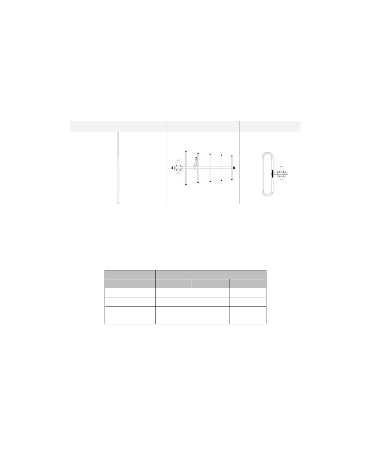
2.5.2 Omni Directional Antenna
In general, an omni directional antenna should be used at a master station and Relay
Points. This allows equal coverage to all of the remote locations. Omni directional antennas
are designed to radiate the RF signal in a 360-degree pattern around the antenna. Short
range antennas such as folded dipoles and ground independent whips are used to radiate
the signal in a ball shaped pattern while high gain omni antennas, such as a collinear
antenna, compress the RF radiation sphere into the horizontal plane to provide a relatively
flat disc shaped pattern that travels further because more of the energy is radiated in the
horizontal plane.
001-5006-000_FCC.docx Page 22
2.5.3 Yagi Antenna
At remote locations (not used as a Relay Point), a directional Yagi is generally
recommended to minimize interference to and from other users.
2.5.4 Vertical Dipoles
Vertical dipoles are very often mounted in pairs, or sometimes groups of 3 or 4, to achieve
even coverage and to increase gain. The vertical collinear antenna usually consists of
several elements stacked one above the other to achieve similar results.
Figure 2.4 - Antenna Types
Omni (Vertical Collinear)
Yagi
Vertical Dipole
2.5.5 Feedline
The choice of feedline should be carefully considered. Poor quality coaxial cables should be
avoided, as they will degrade system performance for both transmission and reception. The
cable should be kept as short as possible to minimize signal loss. See Table 2.1 for a list of
feedline recommendations.
Table 2.1 - Transmission Loss (per 100 Feet)
Frequency Range
Cable Type
VHF
UHF
900 MHz
LMR-400
1.5 dB
2.7 dB
3.9 dB
1/2” Heliax
0.68 dB
1.51 dB
2.09 dB
7/8” Heliax
0.37 dB
0.83 dB
1.18 dB
1 5/8” Heliax
0.22 dB
0.51 dB
0.69 dB
Outside cable connections should have a weather kit applied to each connection to prevent
moisture. Feedline connections should be routinely inspected to minimize signal loss
through the connection. A 3 dB loss in signal strength due to cable loss and/or bad
connections represents a 50% reduction in signal strength.
2.5.6 RF Exposure Compliance Requirements
The Guardian radio is intended for use in the Industrial Monitoring and Control and SCADA
markets. The Guardian unit must be professionally installed and must ensure a minimum
separation distance listed in the table below between the radiating structure and any
person. An antenna mounted on a pole or tower is the typical installation and in rare
instances, a 1/2-wave whip antenna is used.
001-5006-000_FCC.docx Page 23
Table 2.2 – RF Exposure Compliance Minimum Safety Distances
Antenna Gain
5 dBi
10 dBi
15 dBi
Min Safety Distance
(VHF @ max power)
123cm
218.8cm
389cm
Min Safety Distance
(UHF @ max power)
105.7cm
188cm
334.4cm
Min Safety Distance
(900 MHz @ max power)
63.8cm
115 cm
201.7 cm
Note: It is the responsibility of the user to guarantee compliance with the FCC
MPE regulations when operating this device in a way other than described above.
The Guardian radio uses a low power radio frequency transmitter. The concentrated energy
from an antenna may pose a health hazard. People should not be in front
of the antenna when the transmitter is operating.
The installer of this equipment must ensure the antenna is located or pointed such that it
does not emit an RF field in excess of Health Canada limits for the general population.
Recommended safety guidelines for the human exposure to radio frequency electromagnetic
energy are contained in the Canadian Safety Code 6 (available from Health Canada) and the
Federal Communications Commission (FCC) Bulletin 65.
Any changes or modifications not expressly approved by the party responsible for
compliance (in the country where used) could void the user's authority to operate the
equipment.
2.6 TERRAIN AND SIGNAL STRENGTH
A line of sight path between stations is highly desirable and provides the most reliable
communications link in all cases. A line of sight path can often be achieved by mounting
each station antenna on a tower or other elevated structure that raises it high enough to
clear surrounding terrain and other obstructions.
The requirement for a clear transmission path depends on the distance to be covered by the
system. If the system is to cover a limited distance, say 3-5 miles, then some obstructions
in the transmission path may be tolerable. For longer-range systems, any obstruction could
compromise the performance of the system, or block transmission entirely.
The signal strength (RSSI) at the receiver must exceed the receiver sensitivity by an
amount known as the fade margin to provide reliable operation under various conditions.
Fade margin (expressed in dB) is the maximum tolerable reduction in received signal
strength, which still provides an acceptable signal quality. This compensates for reduced
signal strength due to multi-path, slight antenna movement or changing atmospheric
losses. CalAmp recommends a 30 dB fade margin for most projects. Table 2.3 shows the
RSSI versus Reliability.
RF Exposure

001-5006-000_FCC.docx Page 24
Table 2.3 RSSI Reliability
RSSI
Reliability
-100 dBm
Approximately 50% reliability. Fading may cause frequent data loss.
-90 dBm
Approximately 90% reliability. Fading will cause occasional data loss.
-80 dBm
Approximately 99% reliability. Reasonable tolerance to most fading.
-70 dBm
Approximately 99.9% reliability with high tolerance to fading.
2.7 RADIO INTERFERENCE
Interference is possible in any radio system. However, since the Guardian is designed for
use in a licensed system, interference is less likely because geographic location and existing
operating frequencies are normally taken into account when allocating frequencies.
The risk of interference can be further reduced through prudent system design and
configuration. Allow adequate separation between frequencies and radio systems. Keep the
following points in mind when setting up your radio system.
a. Systems installed in lightly populated areas are least likely to encounter interference,
while those in urban and suburban areas are more likely to be affected by other
devices.
b. Directional antennas should be used at the remote end of the link. They confine the
transmission and reception pattern to a comparatively narrow beam, which
minimizes interference to and from stations located outside the pattern.
c. If interference is suspected from another system, it may be helpful to use antenna
polarization opposite to the interfering system’s antennas. An additional 20 dB (or
more) of attenuation to interference can be achieved by using opposite antenna
polarization.
d. Check with your CalAmp sales representative or CalAmp Technical Services for
additional options. The Technical Services group has qualified personnel to help
resolve your RF issues.

001-5006-000_FCC.docx Page 25
CALAMP GUARDIAN QUICK START
3
3
S
Se
et
tu
up
p
a
an
nd
d
C
Co
on
nf
fi
ig
gu
ur
ra
at
ti
io
on
n
It is easy to set up a Guardian network to verify basic unit operation and experiment with
network designs and configurations.
3.1 INSTALL THE ANTENNA
An RX/TX antenna is required for basic operation. For demo units only, connect the antenna
as shown in Figure 3.1 to provide stable radio communications between demo devices.
Figure 3.1 -Demo Antenna Assembly
Note:
It is important to use attenuation between all demo units in the test network to reduce the
amount of signal strength in the test environment.
3.2 MEASURE AND CONNECT PRIMARY POWER
Primary power for the Guardian must be within 10-30 VDC and be capable of providing a
minimum of 10 watt supply for Tx @ 1W, 40 watt supply for Tx @ 5W, or 60 watt supply for
Tx @ 10 W. (In Guardian Demo Kits, a power connector with screw-terminals is provided
with each unit.) Observe proper polarity when connecting the cables to the Power Supply.
(White wire must be connected to red wire.)
3.3 CONNECT GUARDIAN TO PROGRAMMING PC
Connection to a Guardian is established through an RS-232 cable connected to the setup
port of the Guardian and the COM port of the PC
3.4 GUARDIAN FIELD PROGRAMMING SOFTWARE
Operating characteristics of the Guardian are configured by the Field Programming
Software. Offline Diagnostics and Online Diagnostics give access to Offline Diagnostics and
commands (local and remote) and online diagnostics monitoring (with or without a T-
Base/R). Programming software is Windows® based and requires a Windows 95 or better
operating system. Context sensitive help and printable help files are provided with this
program.
The GUARDIAN requires the use of the Field Programming Software for
configuration, adjustment and diagnostics.
20 dB, 5 watt max, attenuator

001-5006-000_FCC.docx Page 26
4
4
U
UN
NI
IT
T
S
ST
TA
AT
TU
US
S
The Unit Status windows display device General and Diagnostic information.
4.1 UNIT IDENTIFICATION AND STATUS
Each Guardian has addressing capability which is used for diagnostics and remote
commands only.
ID Number
This value (maximum 1023) is assigned at the factory but may be modified using the Field
Programming Software. The ID Number is used to uniquely identify the Guardian for remote
commands and Offline Diagnostics. The ID Number may have values within the range of 1
to 4294967295 but multiples of 1024 should not be used
Short ID
This value (maximum 1023) is the low order 10 bits of the ID Number. It is used to identify
online diagnostics only. It may not be modified directly using the Field Programming
Software; it is always derived from the ID Number. All units within a network should have
unique Short ID numbers to avoid ambiguity in Online Diagnostics reports.
The Guardian Field Programming Software may be used to check the value of the Short ID.
When setting up a network, we recommend checking each unit to make sure there is no
duplication of Short ID numbers. Duplications may be resolved by changing the Short ID
Number.
If ID Numbers are set within the range of 1 to 1023, the ID Number and the Short ID will
always have the same value (see Table 1-4).
4.2 DIAGNOSTICS
Guardian units continually monitor and report on their environmental and operating
conditions.
4.2.1 Online Diagnostics
Information is automatically sent by each unit at the beginning of every transmission.
May be disabled for back compatibility with Dataradio T-Modem 96 or Motorola RNet 9600.
Online Diagnostics (statistics) require the use of a network configuration such as that
specified in the “Network Using T-Base” or “Network Using GUARDIAN for Online
Diagnostics” sections. Online diagnostics do not interfere with normal network operation.
Online diagnostics provide four types of information:
DC Input Voltage
Transceiver Temperature
PA Forward Power
PA Reverse Power
4.2.2 Offline Diagnostics
Offline diagnostics are statistics returned in response to a specific request to a particular
station. The use of this feature requires temporary suspension of user network operation.
Offline diagnostics provide information that is displayed via the Offline Diagnostics utility.
Offline Diagnostics gather and displays five types of information:

001-5006-000_FCC.docx Page 27
Supply Voltage
Analog supply voltage
Internal temperature
Received signal strength (in dBm)
Forward and reverse power in watts
Preamble good & total
Preamble DCD
4.2.3 Remote Commands
Remote commands that may be sent using the Offline Diagnostics utility include:
Get parameters (configuration) from remote unit
Sample network statistics (monitoring online diagnostics)
Get statistics (diagnostics)

001-5006-000_FCC.docx Page 28
5 Using Guardian Software
2.5 GUARDIAN FIELD PROGRAMMING SOFTWARE
2.5.1 Introduction
The GUARDIAN Field Programming Software provides programming and diagnostics for the Dataradio
GUARDIAN
wireless modem. The Field Programming Software allows the user to edit and program user
programmable
settings, interactively tune modem and RF parameters, and monitor diagnostic data from the
GUARDIAN. See
Figure 2-6 for the GUARDIAN Field Programming Software startup screen.
This manual assumes the Field Programming Software has been installed on the user‟s PC with at least
one
operational serial COM Port available.
2.5.2 COM Port Settings
GUARDIAN programming is done through the PC‟s Primary COM Port. Primary and secondary COM
ports are
configured with the Field Programming Software. The programming cable (included in the Programming
Kit - DRL part number 250-4006-001) is connected from the Setup Port on the GUARDIAN to the PC‟s
COM
port configured as the Primary Port. The Port Settings screen of the Field Programming Software is
accessed via the Utilities pull-down menu (see Figure 2-7). The Port Settings screens are used to
configure
the PC‟s serial COM Ports. COM Port parameters are defined in 2.5.2.1. COM Port assignments are
displayed in the bottom status bar of the GUARDIAN Field Programming Software screen.
2-7
001-4006-101
2.5.2.1 COM Port Parameters
COM Port
Selects COM Port number (COM 1-4) for Primary and Secondary COM Ports (see Figure 2-6).
Baud Rate
Selects the communication speed for Primary and Secondary COM Ports.
Data Bits
Selects the number of data bits (4-8) transmitted or received for the Primary and Secondary COM Ports.
Parity
Selects transmission or reception of any Parity Bits for the Primary and Secondary COM Ports.
Stop Bits
Selects number of Stop Bits (1 or 2) transmitted or received for the Primary and Secondary COM Ports.
2-8
001-4006-101
DTR Enable
Used to assert DTR (Data Terminal Ready) line of the RS232 Port when the port is open for the Primary
and
Secondary COM Ports.
Swap COM Ports
Selecting the Swap Com Ports button moves the Secondary COM Port settings to the Primary COM Port
(and moves the Primary COM Port to the Secondary settings). Since GUARDIAN programming is done
through
the Primary COM Port, this is useful when two units are connected to the Primary and Secondary COM
Ports. A Swap COM Ports allows the second unit to be programmed without switching programming
cables.
2.5.2.2 Primary and Secondary Port Settings Communications Modes
001-5006-000_FCC.docx Page 29
The Mode drop down menu configures the communications mode for the Primary and Secondary PC
Port.
See Table 2-6 for Communication Modes configurations.
Table 2-6 Communication Modes
Mode Description
Sync/ESC with No HS Sends data using Sync/byte-stuffing protocol without handshaking.
Buffered with No HS Sends buffered data without handshaking (this mode required for DOX
operation.)
Sync/Esc with RTS/CTS HS Sends data using the Sync/Esc byte-stuffing protocol with RTS/CTS
hardware handshaking.
Buffered with RTS/CTS HS Sends buffered data with RTS/CTS hardware handshaking.
Sync/Esc with Flow Control HS Sends data using the Sync/Esc byte-stuffing protocol with flow control
handshaking.
Buffered with Flow Control HS Sends buffered data with flow control hardware handshaking.
2-9
001-4006-101
2.5.3 Port Statistics
Figure 2-7 Port Statistics Screen
Port Statistics show current parameters of the PC‟s Primary and Secondary COM Ports.
Baud Rate
Baud Rate shows the current baud rate setting for the Primary and Secondary COM ports.
RTS
RTS shows the current state of the RTS (request to send) line. RTS is an output from the PC.
DTR
DTR shows the current state of the DTR (data terminal ready) line. DTR is an output from the PC.
CTS
CTS shows the current state of the CTS (clear to send) line. CTS is an input to the PC.
DSR
DSR shows the current state of the DSR (data set ready) line. DSR is an input to the PC.
DCD
DCD shows the current state of the DCD (data carrier detect) line. DCD is an input to the PC.
2-10
001-4006-101
Bytes Tx‟ed
Bytes Transmitted shows the number of bytes (characters) transmitted since the port was last opened or
cleared.
Bytes Rx‟ed
Bytes Received shows the number of bytes (characters) received since the port was last opened or cleared.
001-5006-000_FCC.docx Page 30
Framing Errors
Framing Errors shows the number of Framing Errors received since the port was last opened or cleared.
2.5.4 Setup Modem/Radio Parameters
Figure 2-8 Setup Modem/Radio Screen
The Setup Modem/Radio Parameters screen is accessed from the Edit menu pull-down or from the Parms
icon when the tool bar is visible.
2.5.4.1 Modem Operating Parameters
The Setup Modem/Radio Parameters allows the user to view and edit GUARDIAN‟s programmable
parameters.
Programming parameters can be stored in a data file with the .DAT file extension. Programmable
parameters are used by the Read/Write Parameters screen for programming into nonvolatile memory.
2-11
001-4006-101
Parameter settings are modified from three screen tabs: the Modem tab, COM/Analog tab, and Radio tab.
When desired parameters in each tab window have been adjusted, select the OK button to store the
parameter information into local PC memory and exit the parameter screen. Clicking the Default Parms
button sets certain parameters back to factory default settings. Clicking Cancel exits the parameter screen
without modifying any parameters currently stored in local PC memory.
Modem operating parameters include:
Long ID
The electronic ID Number is a unique number assigned at the factory. This number may be changed in the
case of a duplication. The ID Number is used by the programmer for remote addressing and diagnostics.
The range of this field is 1 to 4294967295 but multiples of 1024 should not be used. A multiple of 1024
results in a Short ID of 0. If the ID Number is within the range of 1 to 1023, the Short ID will be the
same.
NOTE: This ID is not the same as the printed serial number. Use the printed serial number to verify if the
unit is under warranty.
Short ID
The Short ID is derived from the longer ID Number. It is used to identify units and minimizes the time
required to transmit Online Diagnostics. The Short ID of each unit in a network must be unique if Online
or

001-5006-000_FCC.docx Page 31
Offline Diagnostics will be used. Since the Short ID is derived from the ID Number, no entry is allowed
in
this field. The range of the Short ID is 1 to 1023.
Comment
The Comment field can be used as a notepad (i.e., customer name, location, technical info...etc can be
entered in this field). Comments are text up to 39 characters including spaces.
Date Last Configured
The Date Last Configured field shows the date the unit was last programmed. The date is taken from the
operating program. No entry is allowed in this field.
Total Configurations
The Total Configurations field shows the number of times a unit has been programmed. No entry is
allowed
in this field.
Online Diagnostics
If enabled, diagnostics information is sent at the beginning of each transmission. Diagnostics information
is
invisible to user data except for the increase in RTS/CTS delay of 11ms (at 9600 b/s). The default value is
“Enabled” (checked)
All units in a network must use the same setting. Diagnostics from the last 15 stations heard are stored in
each unit. These values or read using the Offline or Online Diagnostics screen.
2-12
001-4006-101
Transmitted information includes:
� Short ID
� Supply Voltage (in Volts)
� Internal Temperature (in Celsius)
� Forward and Reverse Power (in Watts) (T-96S and GUARDIAN only)
� Received Signal Strength (in dBm)
T-Base Option
Available when connected to a GUARDIAN Wireless Modem, the “T-Base Option” makes the necessary
circuit
changes to allow using the modem as a special diagnostic unit in the T-Base/R. The default value is
“Disabled” (unchecked).
Repeater Mode (Extended T1 RTS-CTS refer to Table 2-8, page 2-13)
The Repeater Mode option extends transmitter turn-on time to allow use in a repeater network. The
default
value is “Disabled” (unchecked).
Extended Turn-off (T2)
The Extended Turn-off option extends transmitter turn-off time to enforce a quiet period at the end of
each
transmission. Select “Enabled” if data equipment does not clearly terminate each data frame and is
susceptible to extraneous bits (dribble bits) at the end of data transmission. The default value is
“Disabled”
(unchecked).
Values are: 4800 b/s = 16 ms; 9600 b/s = 8 ms; 19200 b/s = 4 ms
An end-of-transmission quiet period approximately 8 characters long can be invoked on the GUARDIAN
by
holding its transmitter on briefly after RTS is dropped. This quiet period (which occurs between the last
valid data character and any possible extraneous “noise” bits) may be of benefit to some DTE that would
otherwise be adversely affected by the extraneous bits.
Output Raw Diagnostic Data Only
The Output Raw Diagnostic Data Only option instructs the modem to receive diagnostic information
received from other modems only. Enabling this option disables user data delivery. This function is
provided to use with the Diagnostic Unit incorporated in a T-Base or T-Base/R. The default value for this

001-5006-000_FCC.docx Page 32
option is “Disabled” (unchecked).
Baud Rate
This field selects the RS-232 Interface and Network (over the air) baud rates.
Table 2-7 lists programming possibilities for this field.
2-13
001-4006-101
Table 2-8 RTS/CTS Delays
Data Format
The Data Format field selects the word length and number of stop bits for the data stream. The following
options are available*:
a. 8 Data Bits, 1 Stop Bit
b. 8 Data Bits, 2 Stop Bits
c. 9 Data Bits, 1 Stop Bit
d. 9 Data Bits, 2 Stop Bits
Table 2-8 shows supported user formats and modem programming.
Note: A Yes in the Parity column indicates Even/Odd or Mark/Space Parity. A No in the Parity column
indicates none. N/A means the combination is not available.
Table 2-7 RS-232 Interface and Network Baud Rates
Configuration Baud Rates
Full-Channel GUARDIAN in “GUARDIAN Native” network type 4800, 9600, 19200
Half-Channel GUARDIAN in “GUARDIAN Native” network type 4800, 9600
Full-Channel GUARDIAN in “T-96S/DL3276” network type 4800, 9600
Half-Channel GUARDIAN in “T-96S/DL3276” network type 4800
Full-Channel T-96S 1200, 2400, 4800, 9600
Table 2-9 Supported User Formats and Modem Programming
Data Bits Parity Stop Bits Modem*
7 No 1 N/A
7 Yes 1 a
7 No 2 a
7 Yes 2 b
8 No 1 a
8 Yes 1 b or c
8 No 2 b or c
8 Yes 2 d
9 No 1 c
9 Yes 1 d
9 No 2 d
9 Yes 2 N/A
RTS/CTS delay (normal) RTS/CTS delay (extended)
Product Mode
Speed diag. off diag. on diag. off diag. on
T-96S 4800 b/s 30 ms 54 ms 60 ms 85 ms
T-96S 9600 b/s 30 ms 41 ms 60 ms 75 ms
GUARDIAN 9600 b/s 20 ms 32 ms 40 ms 55 ms
GUARDIAN 19200 b/s 20 ms 28 ms 40 ms 50 ms
2-14
001-4006-101
Note: If 9 Data Bits, 2 Stop Bits is selected, Remote Diagnostics or Commands are not supported and
Online Diagnostics must be disabled for proper network data operation. Important: All units in a network
must use the same Data Format setting.
2.5.4.2 Data Type
Data Type behavior is dependent on the modem connected to the user PC.
� Connected to a GUARDIAN Modem operating in “GUARDIAN Native” network type: Enhanced Only
Data Type
� Connected to a GUARDIAN Modem operating in “T-96S/DL3276” (or Crystal) network type:
Enhanced or
Compatible Data Type
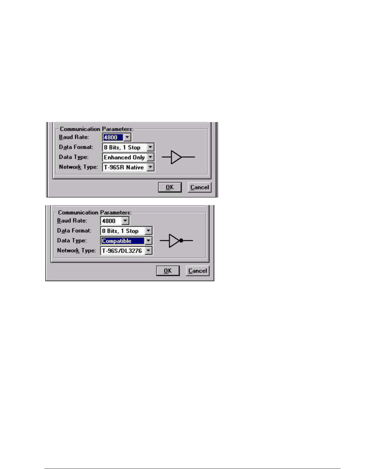
001-5006-000_FCC.docx Page 33
Note: Choose “Compatible” if the modem is to be used with RNet 9600S (crystal) or T-Modem96
(crystal)
units with serial numbers below 103500. The buffer icon to the right of his option will turn to an inverting
buffer when “Compatible” is selected. Choose “Enhanced” for other applications to achieve better
performance. Important: All units in a network must use the same Data Format setting.
2.5.4.3 Network Type
Interdependent with Baud Rate and Data Type, Network Type allows over-the-air compatibility and
varies
according to the products used in the network. Network Type is dependent on the modem connected to
the
user PC.
Figure 2-9 Network Type Connected to a GUARDIAN Modem
Figure 2-10 Network Type Connected to T-96S/DL3276
� Connected to a GUARDIAN Modem, Network Types include:
1.GUARDIAN Native: available Baud Rate options include 4800/9600/19200 for full-channel units or
4800/
9600 for a half-channel units. Data Type is Enhanced Only
2-15
001-4006-101
2.T-96S/DL3276: available Baud Rate options include 4800/9600 for full-channel units or 4800 for
halfchannel
units. Data Type offers two options: Enhanced and Compatible. Compatible causes the buffer
icon to change to an inverting buffer
3.Crystal: available Baud Rate options include 4800/9600 for full-channel units or 4800 for half-channel
units. Data Type offer two options: Enhanced and Compatible. Compatible causes the buffer icon to
change to an inverting buffer. Selecting this Network Type extends all RTS/CTS delays by 5 mS for
compatibility
with crystal units.
� Connected to a T-96S/DL3276 Modem, Network Types include:
1.T-96S/DL3276: available Baud Rate options include 1200/2400/4800/9600 for full-channel units or
1200/2400/4800 for half-channel units. Data Types offer two options: Enhanced and Compatible.
Compatible
causes the buffer icon to change to an inverting buffer
2.Crystal: available Baud Rate options include 1200/2400/4800/9600 for full-channel units or 4800 for
half-channel units. Data Type offer two options: Enhanced and Compatible. Compatible causes the
001-5006-000_FCC.docx Page 34
buffer icon to change to an inverting buffer. Selecting this Network Type extends all RTS/CTS delays by
5 mS for compatibility with crystal units.
Caution: The 9600 Baud Rate (full-channel) in GUARDIAN Native Network Type has faster modem timing and
a higher
deviation than the 9600 Baud Rate in the T-96S/DL3276 Network Type. The two are not interchangeable.
Figure 2-11 Radio Setup Parameters Screen
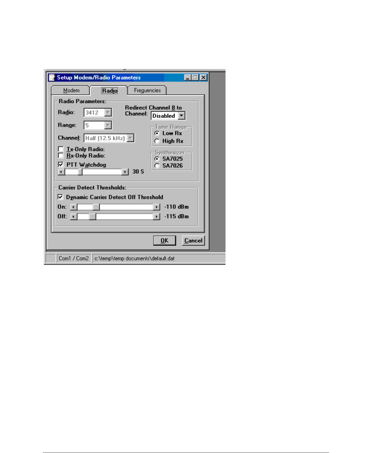
2.5.4.4 Radio Setup Parameters
The Radio tab provides the interface for programming various radio operating parameters (see Figure 2-
11).
2-16
001-4006-101
Radio
This field designates the radio model.
Range
This field designates radio frequency range.
Channel
This field specifies whether the unit is full- or half-channel (12.5 or 25 kHz).
Redirect Channel 8
The Redirect Channel 8 field allows Channel 8 to be directed to another programmed channel. The units‟
DIP switches must be set to the Channel 8 selection for channel redirection to function.
Tx Only Radio
The Tx Only Radio option disables the radio‟s receiver and any ability for the modem to receive data.
This
function is provided for use with the Tx unit incorporated into a T-Base or T-Base/R.
Rx Only Radio
The Rx Only Radio option disables the radio‟s transmitter and any ability for the modem to transmit data.
This function is provided for use with the Rx unit incorporated into a T-Base or T-Base/R.
PTT Watchdog
001-5006-000_FCC.docx Page 35
The PTT Watchdog allows the user to set the maximum transmit time. This is used to protect against a
„stuck‟ transmitter. The time is selected by a slider bar. The range is 0 to 120 seconds with a default of 30
seconds. Warning: Transmissions longer than 30 seconds may exceed the duty cycle rating of the
transmitter
and lead to shortened life or transmitter failure. A factory-installed cooling fan is available for extended
duty operations. For continuous-transmit applications, the PTT Watchdog feature can be disabled
(unchecked).
Synthesizer
This field lists the synthesizer model used. This field is non-selectable and for reference only.
Dynamic Carrier Detect Off Threshold
The Dynamic Carrier Detect Off Threshold allows the modem to automatically adjust the Carrier Detect
Off Threshold based on the RSSI while receiving data. If selected, the Carrier Detect Off level will
automatically adjust to approximately 15 dB below the actual signal strength. This provides rapid
detection
of loss-of-carrier and minimizes or eliminates „bit dribble‟ at the end of transmissions.
Recommendation: Keep Dynamic Carrier Detect Off Threshold enabled (checked) unless interference or
variable signal strength (i.e., fading in a moving vehicle) causes problems.
2-17
001-4006-101
Carrier Detect On Threshold
Carrier Detect On Threshold indicates RSSI level when a carrier is found. This level should be more than
the Carrier Detect Off Threshold.
Carrier Detect Off Threshold
Carrier Detect Off Threshold indicates the RSSI level when a carrier is lost. This level should be less than
the Carrier Detect On.
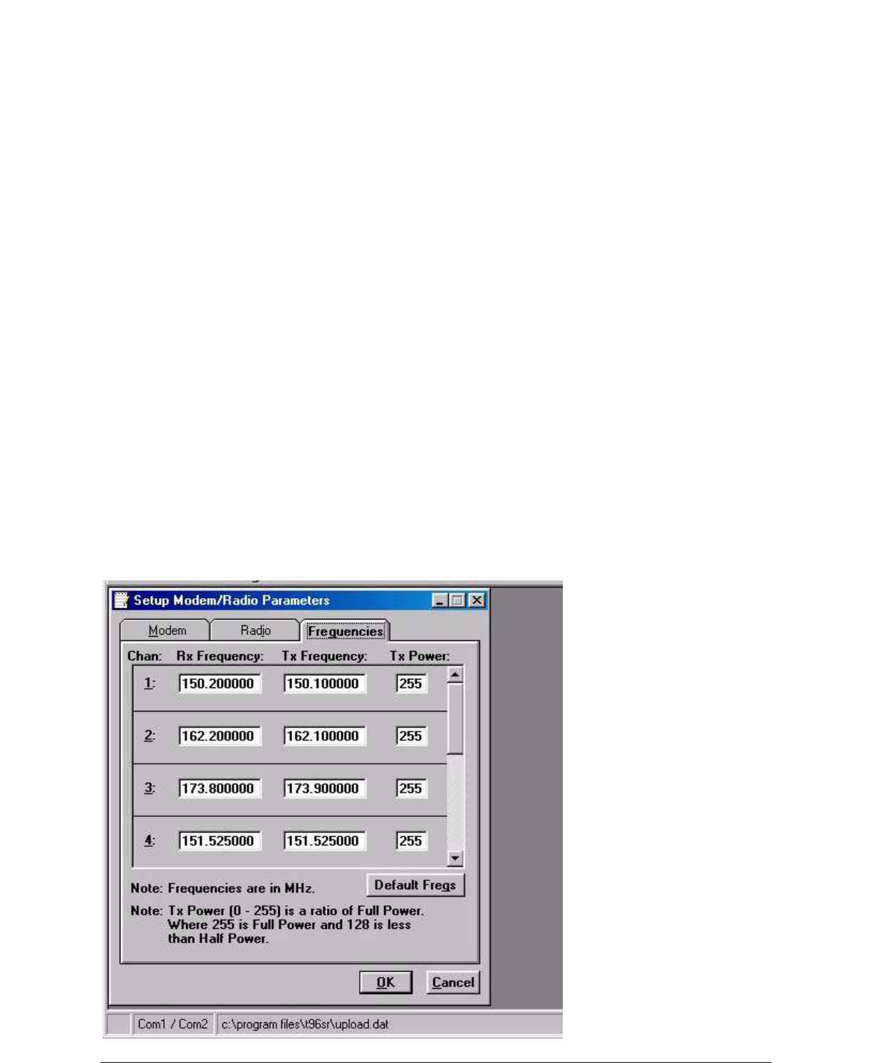
2.5.4.5 Setup Modem/Radio Frequencies
The Frequencies tab provides the interface to program frequency pairs and their corresponding power
settings.
Figure 2-12 Setup Radio/Modem Frequencies Parameters
001-5006-000_FCC.docx Page 36
Chan
Chan displays the frequency channel pair.
Rx Frequency
Rx Frequency displays the receive frequency for the channel pair.
2-18
001-4006-101
Tx Frequency
Tx Frequency displays the transmit frequency for the channel pair.
Power
Power displays the Power Output Adjust value for the channel pair. The default value is 255 (5 watts).
This
value should be left at the default value unless:
� a lower power is required to meet regulatory requirements or
� the user‟s application requires an increase in the transmit duty cycle
Default Freqs
The Default Freqs button forces the Rx and Tx Frequencies to their default values, based on radio type
and
range.
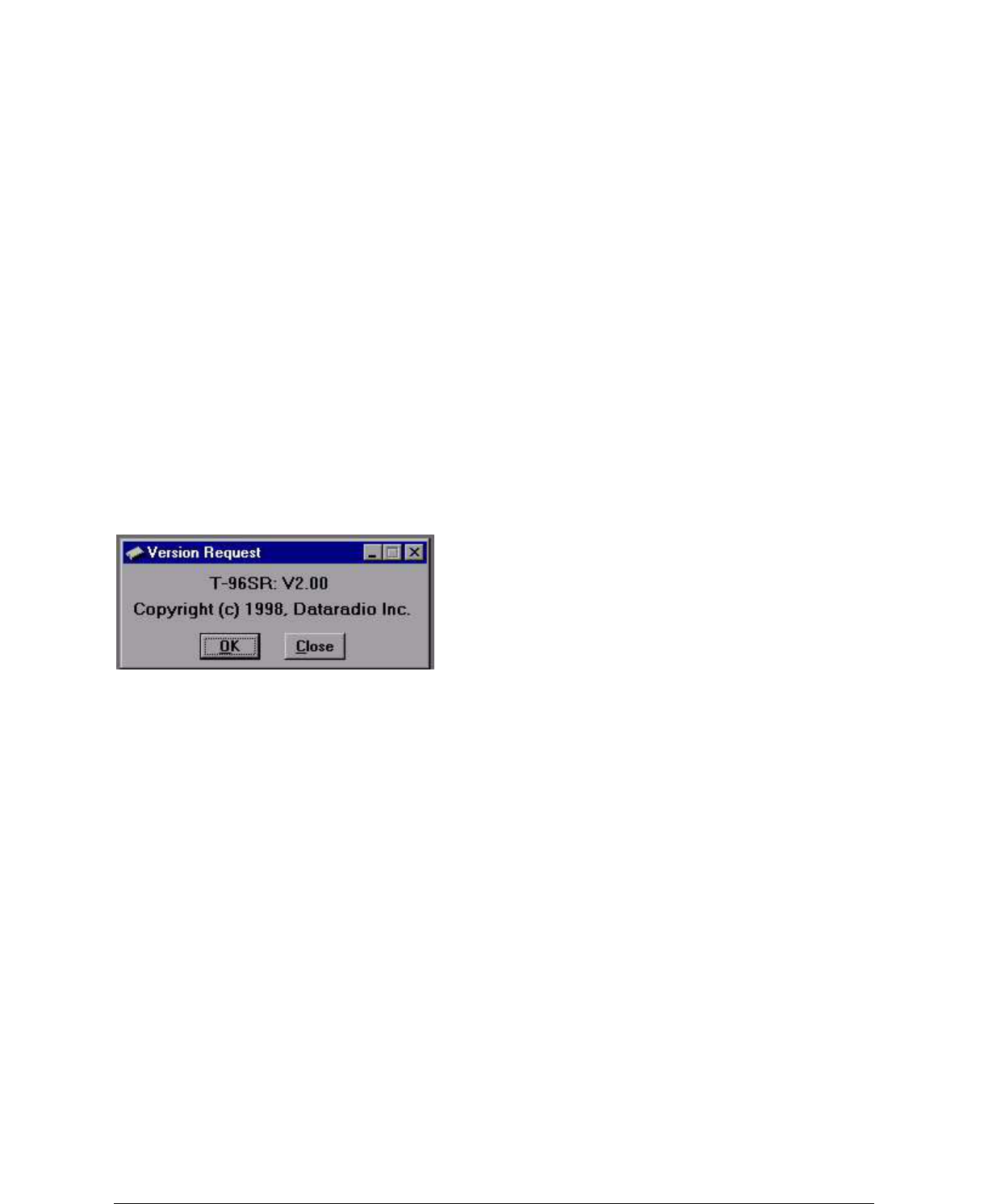
2.5.5 VERSION REQUEST
Selecting Version Request causes the GUARDIAN Field Programming Software to display information
about the
version of the GUARDIAN hardware and firmware.
Figure 2-13 Version Request Screen
2.5.6 WRITING / READING GUARDIAN PARAMETERS
After all radio parameters are setup, select the OK button to store the information into the PC‟s
memory. To load parameters into the GUARDIAN, initiate a Write Programmable Settings from the
Edit menu or select the Write icon from the Tool Bar. After the programmable parameters are
loaded into the GUARDIAN, save the parameter information using the Save Data As option in the File
pull-down menu.The name and location of the file (*.dat extension) will appear on the status bar at the
bottom of the screen.
The Read Programmable Settings command will read parameters from the current GUARDIAN and
store the information in local memory. The parameters can be viewed and/or edited with the
Setup Modem/Radio Parameters screens.
2.02
2-19
001-4006-101
Note: Dataradio recommends a Read be done anytime an initial connection is made to the GUARDIAN
Setup
Port before accessing the Setup Modem/Radio Parameters screen. This will help avoid writing erroneous
parameters to the connected unit.
2.5.7 CLONE PROGRAMMABLE PARAMETERS
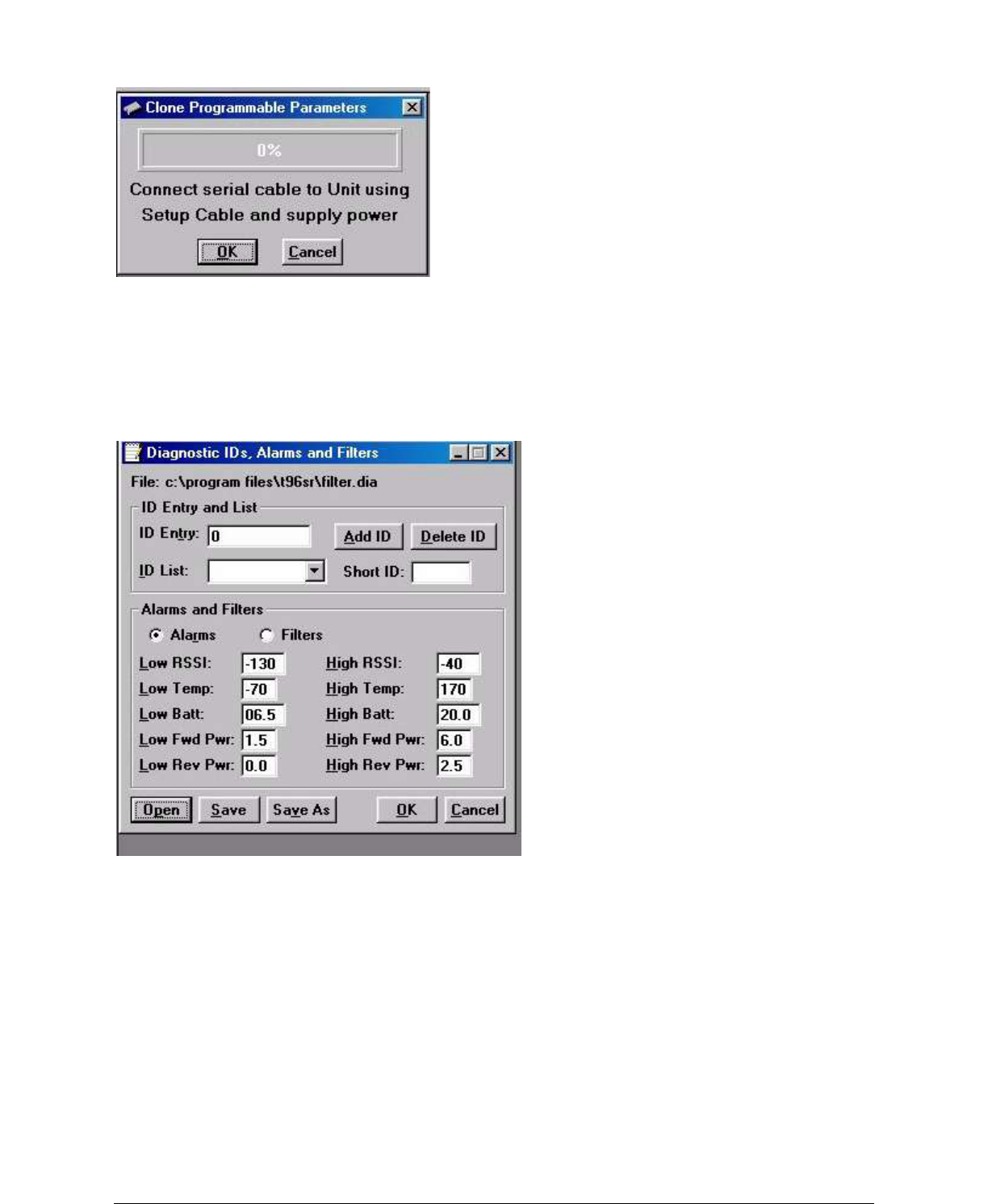
001-5006-000_FCC.docx Page 37
Figure 2-14 Clone Programmable Parameters Screen
The Clone Programmable Settings writes the currently loaded settings (except the ID Number, Comment,
and Number of Writes) to the EEPROM of the GUARDIAN. This option is used for programming the
same Data
File (.dat) into multiple modems.
2.5.8 DIAGNOSTIC IDS AND ALARMS
The Diagnostics IDs and Alarms screen allows the user to set up the ID List for use with the Offline Link
Test and Offline and Online Diagnostics as well as the Alarms for use with Online Diagnostics.
Figure 2-15 Diagnostic IDs and Alarms Screen
2-20
001-4006-101
ID Entry and List
ID Entry allows the entry of a Long ID to be added to the ID List. The range of this field is 1 to
4294967295 but multiples of 1024 should not be used. A multiple of 1024 results in a Short ID of 0. If the
Long ID is within the range of 1 to 1023, the Short ID will be the same or the resulting Short ID will be
smaller than the Long ID and will be represented by a „+‟ character in front of the ID. A Long ID is added
to the ID List by an „Enter‟ or by pressing the Add ID button.
ID List: Allows the user to select a Long ID from the list to delete. A Long ID is deleted from the list by
pressing the Delete ID button.
Short ID: Shows the converted Short ID from the selected Long ID of the ID List.
Alarms and Filters
Alarms and Filters are used with Online Diagnostics. When Online Diagnostics are received and a
diagnostic field falls outside the Alarm limits, a “<“character will designate a value less than the low
Alarm
and a “>” character will designate a value greater than the High Alarm.
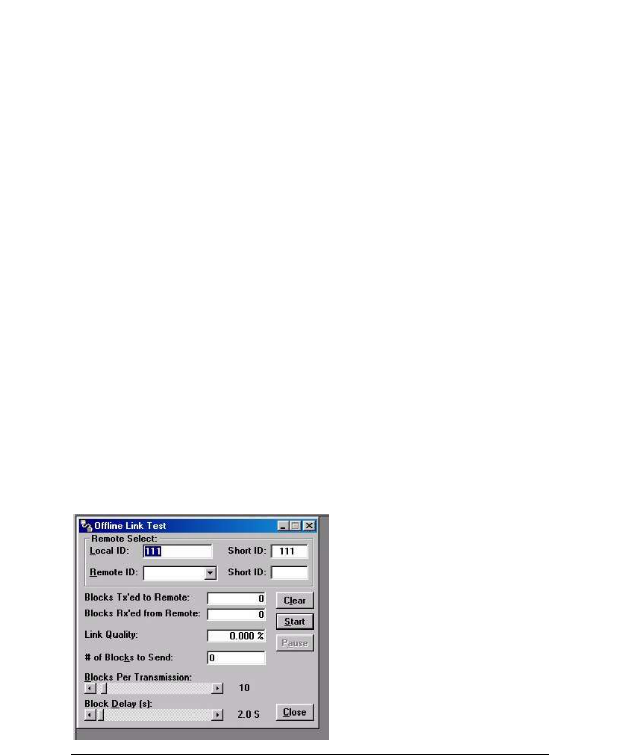
001-5006-000_FCC.docx Page 38
When Online Diagnostics are received and a diagnostic field falls outside the Filter Limits, the diagnostic
information is considered invalid and is not displayed.
Low/High RSSI: Low/High RSSI represent the low and high limits for the RSSI diagnostics (in dBm).
Low/High Temp: The Low/High Temp represents the low and high limits for the temperature diagnostics
(in degrees C).
Low/High Batt: Low/High Batt represents the low and high limits for the battery voltage diagnostics (in
volts).
Low/High Fwd Pwr: Low/High Fwd Pwr represents the low and high limits for the forward power
diagnostics (in watts).
Low/High Rev Pwr:
Low/High Rev Pwr represents the low and high limits for the Reverse Power diagnostics (in watts).
Open
The Open button allows the user to restore Diagnostic IDs and Alarms from a previously saved file.
Save
The Save button allows the user to save the current Diagnostic IDs and Alarms to the current file.
Save As
The Save As button allows the user to save the current Diagnostic IDs and Alarms to a name different
than
the current file.
2-21
001-4006-101
2.5.9 OFFLINE LINK TEST
The Offline Link Test is used to test the link between two units: the local unit interfaced to the computer
and
a remote unit. Blocks of data are transmitted to the remote unit and the remote unit decodes and returns
them. The transmitted and received blocks of data are compared and the ratio of the results are calculated.
NOTE: An Offline Link Test requires suspension of user network operation.
Remote Select
Local ID
The Local ID is the Long ID of the unit connected to the computer. The Short ID is displayed.
Remote ID
The Remote ID combo box allows selection of the unit (by choosing it‟s Remote ID) from which the Link
Test information is gathered. Remote IDs are set up in the Diagnostic IDs and Alarms Screen. The Short
ID
is displayed.
An Offline Link Test returns the following statistics:
Figure 2-16 Offline Link Test Screen

001-5006-000_FCC.docx Page 39
Blocks Tx‟ed to Remote
Blocks Tx‟ed to Remote displays the number of data blocks transmitted to the remote unit.
Blocks Rx‟ed from Remote
Blocks Rx‟ed from Remote displays the number of data blocks received from the remote unit.
2-22
001-4006-101
Link Quality
Link Quality displays the ratio of data blocks received to data blocks transmitted (in %).
# of Blocks to Send
# of Blocks to Send allows the user to determine the number of blocks to send before stopping (with 0
being disabled).
Blocks Per Transmission
Allows the selection of the number of blocks per transmission (1 to 200 blocks).
Block Delay (s)
Block Delay (s) allows the user to determine the delay between the transmission of data blocks in 0.05
second intervals (0.00 to 120.00 seconds).
Clear
Clear allows the user to clear the display (blocks transmitted, blocks received and link quality).
Start
Start is used to begin the test.
Pause
Pause is used to pause the test and allows the user to resume the test at a later time.
2.5.10 OFFLINE DIAGNOSTICS
Offline Diagnostics are returned from a local or remote unit in response to a Get Diags request
(see Figure 2-18). An Offline Diagnostics request requires suspension of user network operation.
Diagnostics
Select
Select allows the user to choose Current, Low or High Diagnostics. Current shows the value of the last
requested parameters. Low or High displays the lowest or highest value of the parameters since the last
Clear was performed or the last time power was removed.
Offline Diagnostics parameters include the following:
� Battery Voltage: supply voltage
� Analog Vcc: Analog Circuits Regulated 5V line
� Temperature: internal case temperature (in Celsius) list continued on next page
2-23
001-4006-101
� RSSI Level: Received Signal Strength Indication (in dBm)
� Forward Power: Forward Power (in watts)
� Reverse Power: Reverse Power (in watts)
� Preamble Good: the number of correctly decoded transmissions received in the last 15. Used with
Preamble Total, this serves as an indication of how well the unit is receiving data
� Preamble Total: the number of total transmissions detected, maximum is 15. Used with Preamble Good,
this serves as an indication of how well the unit is receiving data
� Preamble DCD: this number shows a count of all received Carrier Detects
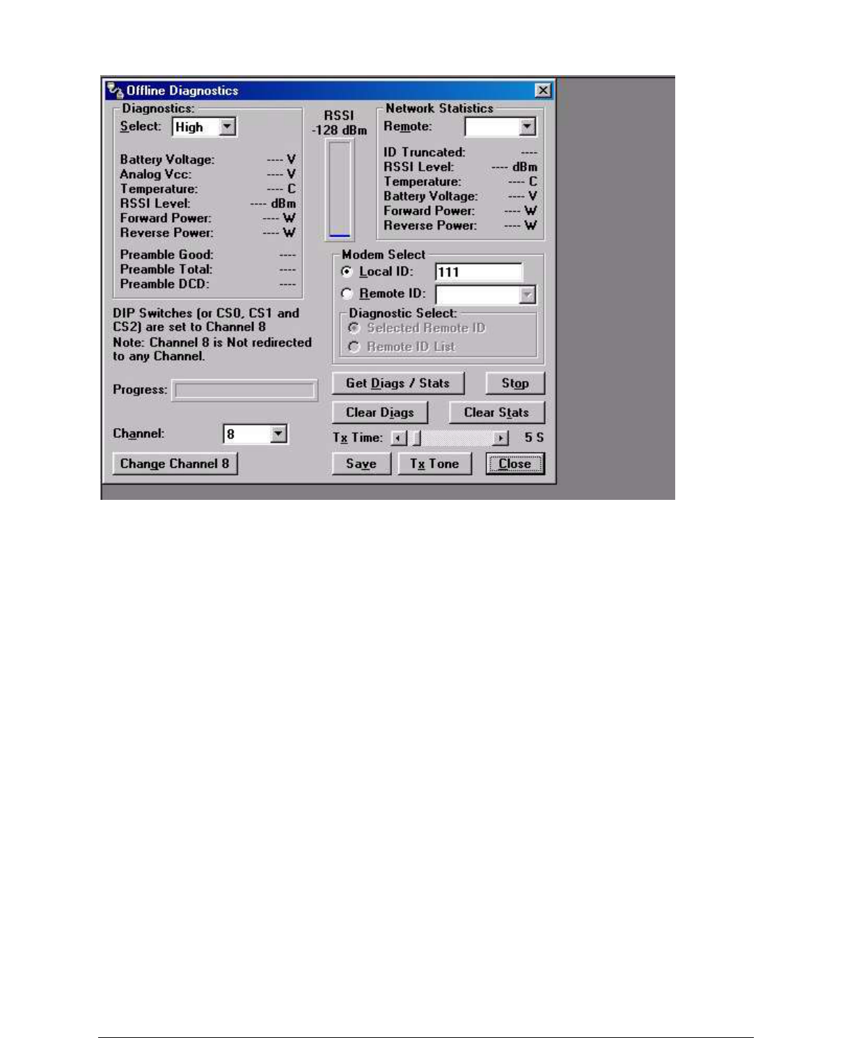
001-5006-000_FCC.docx Page 40
Figure 2-17 Offline Diagnostics Screen
Network Statistics
Offline Network Statistics are only available when the „Online Diagnostics‟ option is enabled for the
network. Online Diagnostics are located on the Setup Modem/Radio Parameters screen. When enabled,
diagnostic information is inserted at the beginning of each transmission from each unit in the network.
While the network may remain online, the monitoring unit is in „Setup‟ mode (flashing green LED).
2-24
001-4006-101
Network Statistics include:
Remote
The Remote drop down allows the user to select (from the list Remotes) which network statistics to
display.
ID Truncated
ID Truncated shows the user the Long and Short ID are not the same.
RSSI Level
The RSSI level shows the current RSSI level (in dBm) while the Local unit is receiving.
Temperature
Temperature shows the internal case temperature (in Celsius).
Battery Voltage
Battery Voltage shows the supply voltage (in Volts).
Forward Power
Forward Power shows forward power (in Watts).
Reverse Power
Reverse Power shows reverse power (in Watts).
RSSI Panel
The RSSI panel shows the current RSSI level (in dBm) while the local unit is receiving.
Modem Select
Local ID
The Local ID button allows the user to send commands to the local unit (the unit interfaced to the
computer). The Short ID for this unit is shown.

001-5006-000_FCC.docx Page 41
Remote ID
The Remote ID button allows the user to send diagnostic commands to any specific remote unit and
obtain
its diagnostic information. The Remote ID is selected from the list of Remote IDs set up in the Diagnostic
IDs and Alarms screen.
Diagnostic Select / Selected Remote ID
This button allows the user to gather Offline Diagnostics from the selected Remote ID only.
2-25
001-4006-101
Diagnostic Select / Remote ID List
This button allows the user to gather Offline Diagnostics from all the IDs in the list of Remote IDs
(including the local unit).
Progress
The Progress panel displays the progress of obtaining Remote Diagnostics.
Channel
Channel allows the user to select the programmed channel of operation. There are 8 programmed
channels.
Change Channel 8
Change Channel 8 allows the user to redirect Channel 8 to another programmed channel. The unit‟s DIP
switches must be set to the Channel 8 selection for channel re-direction to function.
Get Diags / Stats
The Get Diags button allows the user to send the command for Offline Diagnostics. The command is sent
to
the unit connected to the computer if the Local ID button is selected. The command is sent to the selected
Remote ID if the Remote ID and Selected Remote ID buttons are selected. The command is sent to the list
of Remote IDs if the Remote ID and Remote ID List buttons are selected.
Stop
The Stop button allows the user to stop any commands for Offline Diagnostics from being sent.
Clear Diags
Clear Diags clears the unit‟s online network statistics.
Tx Time
Tx Time allows the user to select the length of time the unit will transmit a tone (in seconds) when the Tx
Tone button is pressed (1 to 60 seconds).
Save
The Save button allows the user to save the current Offline Diagnostics to a file.
Tx Tone
The Tx Tone button instructs the unit to transmit a tone for modulation on the programmed transmit
frequency for a duration of Tx Time.
2-26
001-4006-101
2.5.11 ONLINE DIAGNOSTICS
Online Diagnostics are transmitted by each unit in a network before the user‟s data is transmitted. All
units
must be programmed with the Online Diagnostics parameter found on the Setup Modem/Radio
Parameters
screen to receive Diagnostics from a system. The unit that the computer is interfaced with will output
Online Diagnostics as they are received. This unit must have the Output Raw Diagnostic Data Only
parameter programmed (found on the Setup Modem/Radio Parameters Screen). Using Online Diagnostics
does not require suspension of network operation.
Online Diagnostics are subject to alarm and filter conditions defined in the Diagnostic IDs, Alarms and
Filters screen (see Figure 2-15). When Online Diagnostics are received and a diagnostic field falls outside
the alarm limits, a “<“ character will designate a value less than the low alarm and a “>” character will
designate a value greater than the high alarm. If Online Diagnostics are received and a diagnostic field
falls
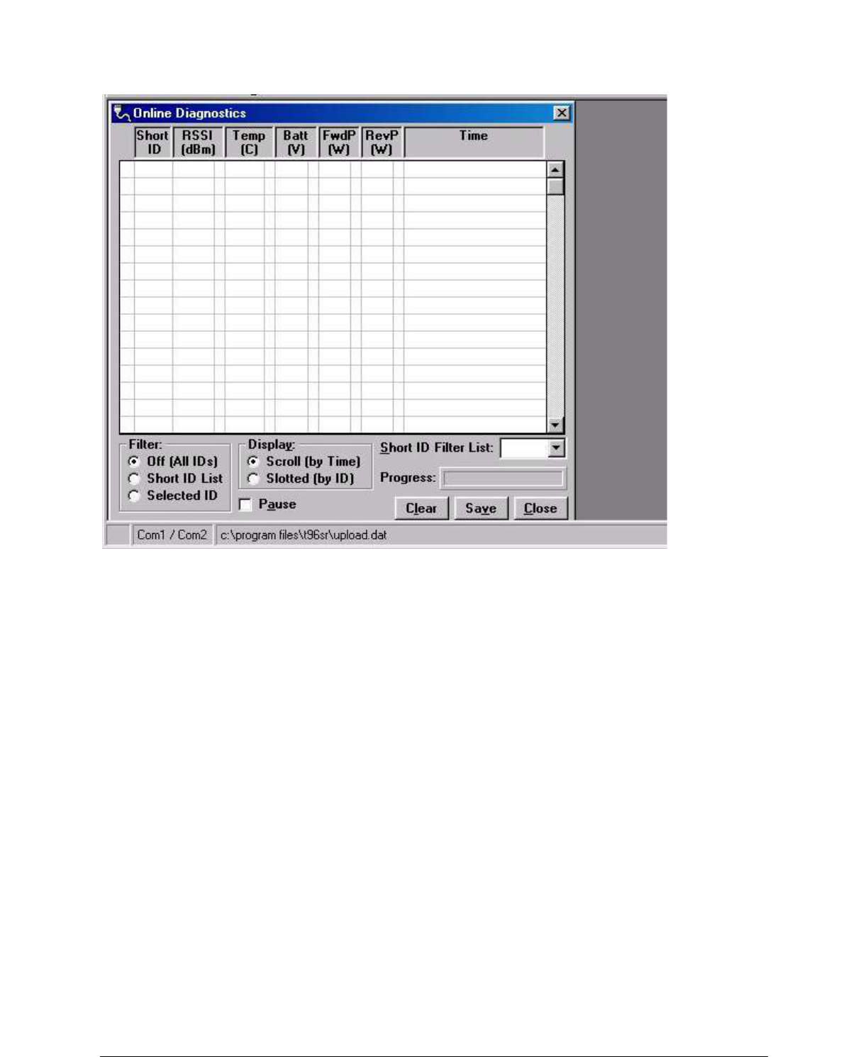
001-5006-000_FCC.docx Page 42
outside the filter limits, the diagnostic information will be considered invalid and will not be displayed.
Figure 2-18 Online Diagnostics
The following Online Diagnostics are gathered:
Short ID
The Short ID displays the Short ID of the unit transmitting the diagnostics.
2-27
001-4006-101
RSSI
RSSI (Received Signal Strength Indicator) displays the RSSI (in dBm) ID of the unit transmitting the
diagnostics. This is the RSSI sampled during the last transmission received.
Temp
Temp displays the internal case temperature (in Celsius) of the unit transmitting the diagnostics.
Batt
Batt displays the supply voltage (in volts) of the unit transmitting the diagnostics.
FwdP
FwdP displays the forward power (in watts) of the unit transmitting the diagnostics.
RevP
RevP displays the reverse (reflected) power (in watts) of the unit transmitting the diagnostics.
Time
Time is the time stamp when the diagnostics were received.
Filter
Filter allows the user to filter Short IDs. The following options are available:
� Off (All IDs): no IDs are filtered out
� ID List: only the IDs in the Filter ID List are shown
� Selected ID: only the selected ID in the Filter ID List is shown
Display
Display allows the user to format on screen data. The following options are available:
� Scroll (by time): displays the diagnostics as they are received
� Slotted (by ID): sorts the diagnostics by Short ID. Using this option, each Short ID will have one row of
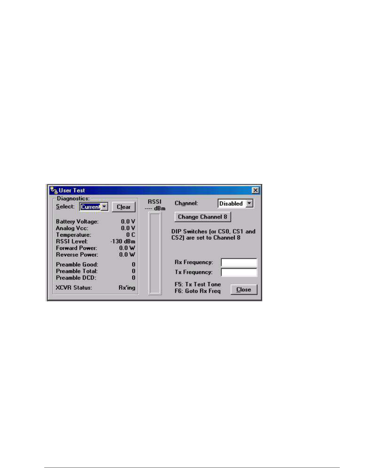
001-5006-000_FCC.docx Page 43
diagnostics, showing the most recent
Short ID Filter List
Filter ID List is a listing of Remote IDs setup in the Diagnostic IDs and Alarms Screen. This list is used
for
selecting a filter.
Progress
The Progress panel shows the sorting progress of the diagnostics if a filter was changed.
2-28
001-4006-101
Pause
The Pause check box allows the user to pause the reception of the diagnostics for scrolling through the
grid.
Clear
The Clear button allows the user to clear the display and current Online Diagnostics.
Save
The Save button allows the user to save the current Online Diagnostics to a file. A maximum of 4096
lines
of data can be saved.
2.5.12 USER TEST
Figure 2-19 User Test Screen
The User Test utility is an Offline function and requires suspension of network operation. A User Test‟s
diagnostic parameters include:
RSSI Level
Received Signal Strength Indication (in dBm)
Battery Voltage
Supply voltage (in volts)
Temperature
Internal temperature (in degrees Celsius)
Forward Power
Forward power (in watts)
2-29
001-4006-101
Reverse Power
Reverse power (in watts)
Preamble Good
The number of correctly decoded transmissions received in the last 15. Used with Preamble Total, this
serves as an indication of how well the unit is receiving data.
Preamble Total
The number of total transmissions detected, maximum is 15. Used with Preamble Good, this serves as an
indication of how well the unit is receiving data.
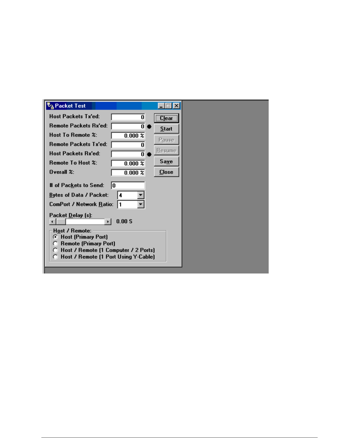
001-5006-000_FCC.docx Page 44
RSSI
This panel shows the current RSSI level (in dBm) while the local unit is receiving.
Rx / Tx Frequency
Rx / Tx Frequency shows the current receive and transmit frequencies.
F5
Pressing the F5 key will cause the unit to transmit on the programmed transmit frequency.
F6
Pressing the F6 key will cause the unit to go to receive on the programmed receive frequency
2.5.13 PACKET TEST
Figure 2-20 Packet Test Screen
2-30
001-4006-101
The Packet Test screen is used to simulate a Host/Remote polling environment. The Master unit will send
out a packet to the Remote and the Remote will reply to the Master with the same packet information.
This
is a useful utility for testing modem communication.
Host Packets Tx‟ed
Host Packets transmitted shows the number of data packets the Master has sent to the Remote.
Remote Packets Rx‟ed
Host Packets received shows the number of data packets the Remote device has received from the Master.
Host to Remote %
Host to Remote percentage shows the percentage of packets the Host device has successfully sent to the
Remote.
Remote Packets Tx‟ed
Remote Packets transmitted shows the number of data packets that the Remote device has returned to the
Host.
Host Packets Rx‟ed
Host Packets received shows the number of data packets the Host device has received from the Remote.
Remote to Host %
Remote to Host percentage shows the number of packets the Remote device successfully sent to the Host.
Overall %

001-5006-000_FCC.docx Page 45
Overall percentage shows the percentage of Host received packets versus Host transmitted packets.
# of Packets to Send
Number of Packets to Send programs the number of packets the Host should send to the Remote before
stopping.
Bytes of Data / Packet
Bytes of Data / Packet is the programmable number of data bytes in each packet the Host sends. The
Remote will respond with the same number of packets.
COMPort/Network Ratio
COMPort/Network Ratio is the ratio of the COM port baud rate to network (over the air) baud rate of a
modem. This is used if the network baud rate is slower than the COM port baud rate. If the COM port
baud
rate is 9600 and the network baud rate is 4800, set the ratio to 2. If the two are the same, set this field to 1.
2-31
001-4006-101
Packet Delay (s)
Packet Delay (s) is the number of seconds for the Host to delay between sending each packet. This field
ranges from 0.00 to 10.00 seconds (in 0.25 second intervals).
Host/Remote
Host/Remote is used to configure COM port options.
� Host (Primary Port) - Configures the primary COM port as the Host device (the device initiating
packets
to the Remote device.
� Remote (Primary Port) - Configures the primary COM port as the Remote device (the device
responding
to the packets from the Host device).
� Host/Remote (1 computer / 2 ports) - Configures the primary COM port as the Host device and the
secondary COM port as the Remote device. This option requires a computer with 2 COM ports.
� Host/Remote (1 Port using a Y-cable) - Configures the primary COM port as the Host and Remote
device.
A Y-cable is required for this option (with transmit connections split to the transmitting device and
receive
connections split to the receiving device). A computer with 1 COM port is utilized for this option
Table 2-10 Y-Cable Connections
Pin Name DB-9 DB-29 Computer Rx Tx
DCD 1 8 X X -
RxD 2 3 X X -
TxD 3 2 X - X
DTR 4 20 - - -
GND 5 7 X X X
DSR 6 6 - - -
RTS 7 4 X - X
CTS 8 5 X - X
RI 9 2 2 - - -
X = Requires connection
- = No connection
2.5.14 ARRAY TEST
The Array Test screen is used to send programmable length test packets. Packets Tx‟ed - total number of
packets transmitted.
# of Packets to Send
# of Packets to Send allows the user to set the total number of packets to send before stopping (field range
is
0 to unlimited)
Table 2-10 Y-Cable Connections
Pin Name DB-9 DB-29 Computer Rx Tx
DCD 1 8 X X -
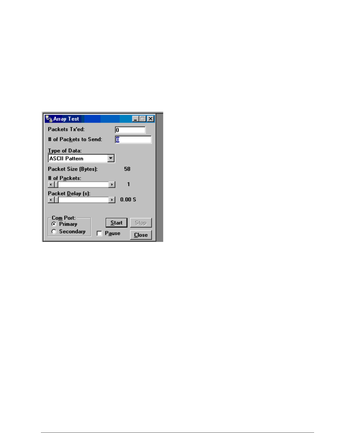
001-5006-000_FCC.docx Page 46
RxD 2 3 X X -
TxD 3 2 X - X
DTR 4 20 - - -
GND 5 7 X X X
DSR 6 6 - - -
RTS 7 4 X - X
CTS 8 5 X - X
RI 9 22 - - -
X = Requires connection
- = No connection
2-32
001-4006-101
Figure 2-21 Array Test Screen
Type of data
Type of Data allows the user to select the data pattern for each packet. The size for each data pattern is
listed in the pattern format explanations (packets are built using one of four possible patterns).
� ASCII Pattern - Packets are 58 characters in length and have a sequence number at the beginning of
each
string starting with 000, incrementing to 999 then wrapping around to 000 again
The pattern used to build the packets will have the following format (in ASCII):
000 ABCDEFGHIJKLMNOPQRSTUVWXYZabcdefghijklmnopqrstuvwxyz
001 ABCDEFGHIJKLMNOPQRSTUVWXYZabcdefghijklmnopqrstuvwxyz
---
998 ABCDEFGHIJKLMNOPQRSTUVWXYZabcdefghijklmnopqrstuvwxyz
999 ABCDEFGHIJKLMNOPQRSTUVWXYZabcdefghijklmnopqrstuvwxyz
000 ABCDEFGHIJKLMNOPQRSTUVWXYZabcdefghijklmnopqrstuvwxyz
001 ABCDEFGHIJKLMNOPQRSTUVWXYZabcdefghijklmnopqrstuvwxyz
---
� ASCII Number Pattern - The packets will be 58 characters in length and have a sequence number at the
beginning of each string, starting at 000 and incrementing to 999, then wrapping around to 000 again.
The pattern used to build the packets will have the following format (in ASCII):
000 00 11 22 33 44 55 66 77 88 99 AA BB CC DD EE FF
001 00 11 22 33 44 55 66 77 88 99 AA BB CC DD EE FF
---
998 00 11 22 33 44 55 66 77 88 99 AA BB CC DD EE FF
999 00 11 22 33 44 55 66 77 88 99 AA BB CC DD EE FF
000 00 11 22 33 44 55 66 77 88 99 AA BB CC DD EE FF

001-5006-000_FCC.docx Page 47
001 00 11 22 33 44 55 66 77 88 99 AA BB CC DD EE FF
---
2-33
001-4006-101
� Binary Pattern - The packets will be 16 characters in length and have a sequence number every 16
characters, starting at 0x00 and incrementing to 0xFF, then wrapping around to 0x00 again.
The pattern used to build the packets will have the following format (in Hex):
00 11 22 33 44 55 66 77 88 99 AA BB CC DD EE FF
01 11 22 33 44 55 66 77 88 99 AA BB CC DD EE FF
02 11 22 33 44 55 66 77 88 99 AA BB CC DD EE FF
-- 11 22 33 44 55 66 77 88 99 AA BB CC DD EE FF
FE 11 22 33 44 55 66 77 88 99 AA BB CC DD EE FF
FF 11 22 33 44 55 66 77 88 99 AA BB CC DD EE FF
00 11 22 33 44 55 66 77 88 99 AA BB CC DD EE FF
01 11 22 33 44 55 66 77 88 99 AA BB CC DD EE FF
02 11 22 33 44 55 66 77 88 99 AA BB CC DD EE FF
-- 11 22 33 44 55 66 77 88 99 AA BB CC DD EE FF
� Random Binary Pattern - The packets will be 16 characters in length and contain random binary data.
# of Packets
# of Packets allows the user to set the number of packets in each transmission.
Packet Delay
Packet Delay allows the user to set the amount of time (in seconds) to delay between each packet
transmission, ranging from 0.00 to 30.00 seconds (in 0.25 second intervals).
Com Port
Com Port allows the user to select the COM port (primary or secondary) for data transmission.
2.5.15 ASCII / HEX TERMINAL
Terminal Screens allow the user to select an ASCII or Hexadecimal Terminal Screen for the Primary and
Secondary COM Ports (configured in the Port Settings screen - see Section 2.5.2.1) Data is sent according
to the port configuration set up in the Port Settings screen.
2-34
001-4006-101
ASCII / HEX TERMINAL
Terminal Screens allow the user to select an ASCII or Hexadecimal Terminal Screen for the Primary and
Secondary COM Ports (configured in the Port Settings screen - see Section 2.5.2.1) Data is sent according
to the port configuration set up in the Port Settings screen.
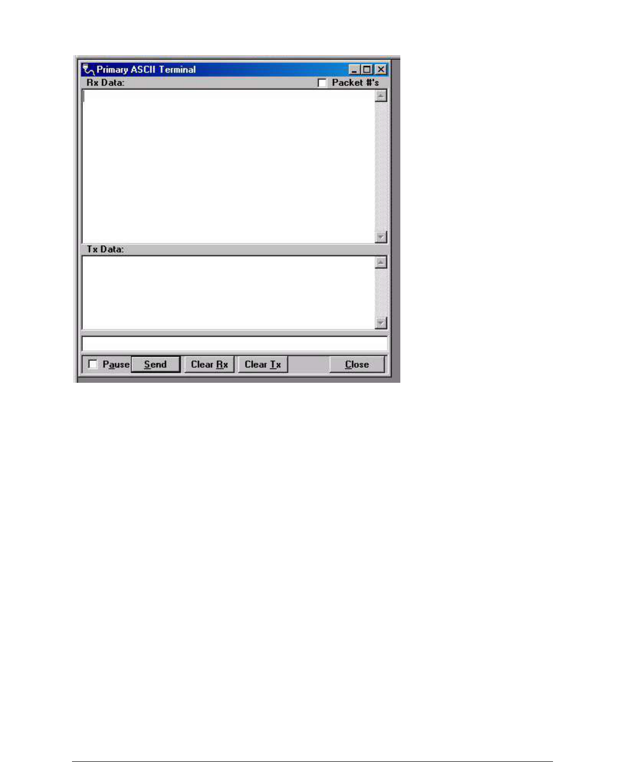
001-5006-000_FCC.docx Page 48
Figure 2-22 ASCII Terminal Screen
2.5.15.1 ASCII Terminal
ASCII Terminal configurations include:
Primary
The Primary ASCII Terminal screen sends and receives ASCII data on the Primary COM Port (set up in
the
Port Settings screen).
Secondary
The Secondary ASCII Terminal screen sends and receives ASCII data on the Secondary COM Port (set
up
in the Port Settings screen).
2.5.15.2 HEX Terminal
Hex Terminal configurations include:
2-35
001-4006-101
Primary
The Primary Hex Terminal screen selects a Hexadecimal Terminal screen to send and receive
Hexadecimal
data on the Primary COM Port (set up in the Port Settings screen).
Secondary
The Secondary Hex Terminal screen selects a Hexadecimal Terminal screen to send and receive
Hexadecimal data on the Secondary COM Port (set up in the Port Settings screen).
2.5.16 PROGRAM CODE
The Program Code pull-down menu allows the user to update the GUARDIAN firmware (*.bin) with the
Program Firmware option. Select Modem Code File allows the user to select the file to program the
firmware in the GUARDIAN.
2.5.17 END TO END TEST
Two Dataradio GUARDIANs can be tested using the Dataradio GUARDIAN Field Programming
Software. The Field
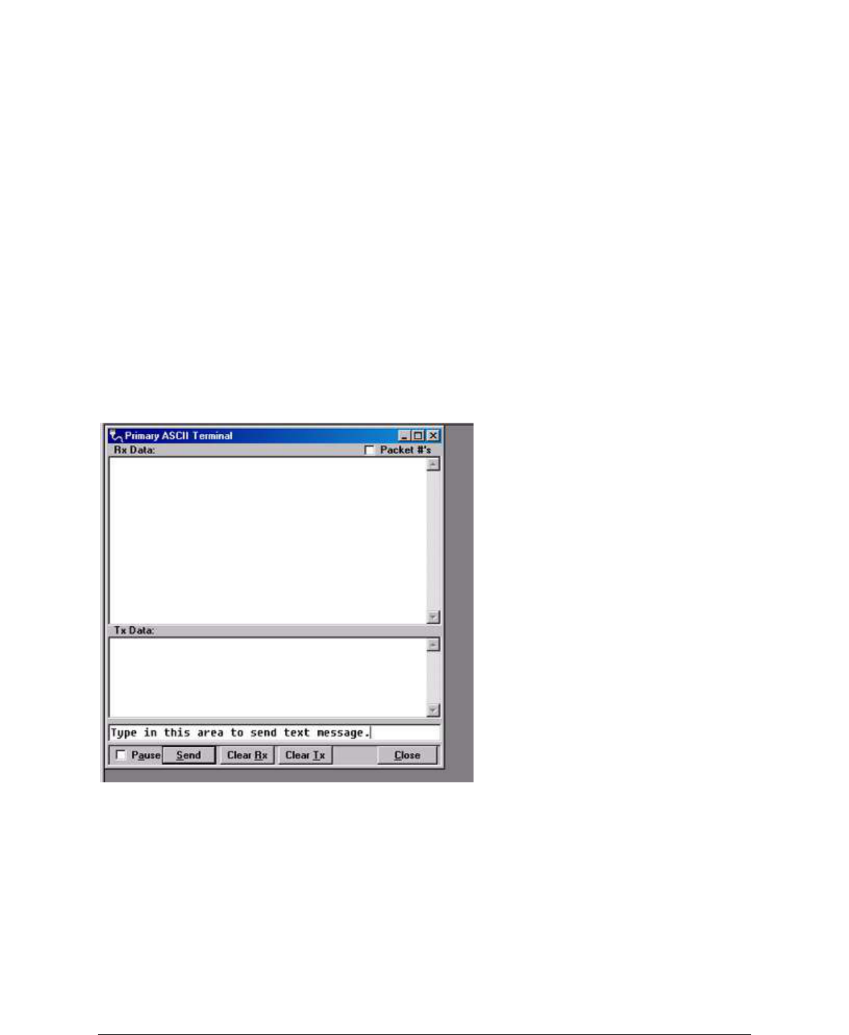
001-5006-000_FCC.docx Page 49
Programming Software has several useful utilities embedded in the program that assist in testing the
wireless modems. The testing setup requires a computer running the Field Programming Software
attached
to each user COM port on the GUARDIAN wireless modems. The Utilities will allow the user to send
ASCII text
or Hex characters through the GUARDIANs being tested.
The GUARDIANs must be setup so that they have the appropriate receive and transmit signal levels for
the test.
The signal strength will be much stronger if the units are tested on the bench compared to being tested in
a
field installation. These signals must be attenuated or the output power level adjusted if the units are being
tested on the bench.
Under the “Utilities” menu choose the “ASCII Terminal”. From the “ASCII Terminal” screen, choose the
“Primary” selection. This will open an ASCII terminal window using the primary COM port of the
computer. This procedure should be done for both GUARDIANs.
The ASCII Terminal utility has provisions for transmitting the ASCII data, displaying received ASCII
data
and displaying ASCII transmitted data. Figure 2-23 shows the window for the Primary ASCII Terminal.
2-36
001-4006-101
Figure 2-23 End to End Test: ASCII Terminal
Figure 2-23 also shows the area that is used to send an ASCII text message. The ASCII data message is
typed into this area. The ASCII text message is then sent out the first GUARDIAN through the
computer‟s
primary port once the “Send “button is clicked. The sent ASCII message is then displayed in the Tx Data
area of the ASCII Terminal window as shown in Figure 2-24.

001-5006-000_FCC.docx Page 50
Figure 2-24 End to End Test: Text message sent
The ASCII message is transmitted to the other GUARDIAN. The ASCII terminal program will display
the
received ASCII message in the Rx Data area as shown Figure 2-25.
Type in this area to send the text message
2-37
001-4006-101
Figure 2-25 Text message received
If the message was not displayed as typed, then a problem may exist in the system. Check all parameters
and connections in the system. The signal level should also be checked again. The GUARDIAN‟s Link
Test
utility can be used to verify a communication path.
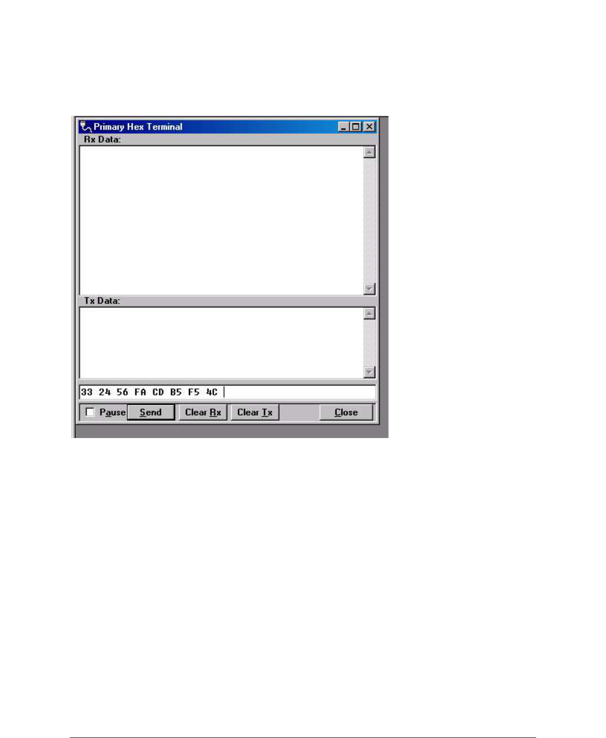
001-5006-000_FCC.docx Page 51
The previous procedure can also be used with the Hex Terminal utility. When the Hex Terminal is used,
the
information is entered as hex code. Figure 2-26 shows how the information will look when it is typed in
and
sent in hex.
Figure 2-26 Hex Terminal
In the Hex Terminal mode, the program will not transmit ASCII information. It will only allow valid hex
characters.

001-5006-000_FCC.docx Page 52
– APPENDIX A –
G
GU
UA
AR
RD
DI
IA
AN
N
S
SP
PE
EC
CI
IF
FI
IC
CA
AT
TI
IO
ON
NS
S
These specifications are typical and subject to change without notice.
GENERAL
VHF
UHF
900
Model Numbers
140-5016-50x
140-5026-50x
140-5046-30x
140-5046-400 (ETSI, AS/NZ)
140-5046-50x
140-5046-600 (AS/NZ)
140-5096-50x
Frequency Range (MHz)
136 – 174 MHz
215 – 240 MHz
406.125 – 470.000 MHz,
406.125 – 470.000 MHz,
450.000 - 511.975 MHz
450.000 - 511.975 MHz
928 – 960 MHz
Frequency Stability
1.0 ppm
1.0 ppm
1.0 ppm
Channel Bandwidth
6.25 kHz
12.5 kHz
25 kHz
50 kHz (215 – 240 MHz only)
6.25 kHz
12.5 kHz
25 kHz
12.5 kHz (ETSI, AS/NZ certified)
25 kHz (ETSI, AS/NZ certified)
12.5 kHz
25 kHz
Modes of Operation
Simplex, Half-Duplex
Frequency Increment
1.25 kHz
Power Source
10-30 VDC, Negative GND
The Guardian is UL approved when powered with a listed Class 2 power
supply.
RF Impedance
50 Ω
Operating Temperature
-30° to + 60° C
Storage Temperature
-40° to + 85° C, 95% non-condensing RH
Operating Humidity
5% to 95% non-condensing RH
Rx Current Drain at 25°C
DC Input 10V
DC Input 20V
DC Input 30V
520 mA (max)
450 mA (typ)
270 mA (max)
240 mA (typ)
190 mA (max)
170 mA (typ)
Tx Current Drain at 25°C
Power Out
DC Input 10V
DC Input 20V
DC Input 30V
Max Pwr
5.8 A (max)
3.6 A (typ)
2.5 A (max)
1.8 A (typ)
1.6 A (max)
1.2 A (typ)
30 dBm
(1W)
1.6 A (max)
1.2 A (typ)
0.8 A (max)
0.6 A (typ)
0.6 A (max)
0.4 A (typ)
Cold start
20 seconds
Nominal Dimensions
5.50" W x 2.125” H x 4.25" D (13.97 x 5.40 x 10.8 cm)
Shipping Weight
2.4 lbs. (1.1 Kg)
Mounting Options
Mounting plate/pattern & DIN Rail
Fan Output
5VDC, 400mA max.
TRANSMITTER
VHF
UHF
900
Tx Frequencies
136 - 174 MHz
215 – 240 MHz
406.125 – 470.000 MHz,
450.000 - 511.975 MHz
928 - 960 MHz
Carrier Output Power
1-10 Watts
Adjustable
1-10 Watts
Adjustable
1-8 Watts
Adjustable
Duty Cycle
100% (Power Foldback Allowed for High Temperatures)
Radiated Spurious Emissions
Per FCC/Regulatory
Conducted Spurious Emissions
Per FCC/Regulatory

001-5006-000_FCC.docx Page 53
Transmitter Stability into VSWR:
> 10:1 (Power Foldback Allowed)
RX to TX Time
< 2 ms (Standard)
4 ms (ETSI Versions)
Channel Switching Time
< 15 ms (Band-End to Band-End)
RECEIVER
Bandwidth
Bit Rate
140-5016-
50x
140-5026-
50x
140-5046-30x
140-5046-50x
140-5096-
50x
Units
RX Frequencies
136 - 174
215 - 240
406.125 – 470.000
450.000 - 511.975
928 - 960
MHz
MHz
Data Sensitivity
@ 10-6 Bit Error
Rate (BER)
Typical / Max
12.5 kHz
8 kbps
16 kbps
-116 / -114
-109 / -106
-116 / -114
-109 / -106
-116 / -114
-109 / -106
-112 / -109
-106 / -103
dBm
dBm
25 kHz
16 kbps
32 kbps
-114 / -111
-106 / -103
-114 / -111
-106 / -103
-114 / -111
-106 / -103
-111 / -108
-104 / -101
dBm
dBm
Adjacent Channel
Rejection (min)
12.5 kHz
60
60
60
60
dB
25 kHz
75
70
75
70
dB
Spurious
Response
Rejection
All
> 75 dB
dB
Intermodulation
Rejection
All
> 75 dB
dB
TX to RX Time
All
< 1 ms (Standard)
5 ms (ETSI Versions)
ms
Channel
Switching Time
All
< 15ms (Band-End to Band-End)
ms
Receive Input
Power
All
17 dBm (50mW) max.
dBm
001-5006-000_FCC.docx Page 54
MODEM/LOGIC
Model
12.5 kHz
25 kHz
Data Rate (Selectable)
140-5016-50x
4800
9600
4800
9600
19200
140-5026-50x
4800
9600
4800
9600
19200
140-5046-30x
4800
9600
4800
9600
19200
140-5046-50x
4800
9600
4800
9600
19200
140-5096-50x
4800
9600
4800
9600
19200
Modulation Type
Addressing
IP
SETUP and COM Port
Interface
EIA-232F DCE
Data Rate
Setup Port: 300 – 19,200 bps (Default: 19.2 Kbps)
Com Port: 300 – 115,200 bps (Default: 9.6 Kbps)
Display
5 Tri-color status LEDs
Power, Status, Activity, Link, Rx/Tx
Connectors
Antenna Connector
TNC female (Tx/Rx)
Serial Setup Port
DE-9F
Serial Terminal Server
DE-9F
Ethernet RJ-45
10 BaseT auto-MDIX
Power - I/O
Power Header
Power Plug
DRL p/n 415-7108-113
(Weidmüller p/n 1615550000)
4 Pin, 3.5mm, Power Header
DRL p/n 897-5008-010
(Weidmüller p/n 1639260000)
4 Pin, 3.5mm, Power Plug
Cable: 60 inches
Connections: Fan Output, Ground,
Power, Enable
Diagnostics
Message elements
Temperature, Voltage, Local RSSI, Remote RSSI, Forward Power, Reverse Power,
Packet Error Rate
001-5006-000_FCC.docx Page 55
UL Certification
All models
UL approved when powered with a listed Class 2 source.
Domestic and International Certifications
Model Number
Frequency Range
FCC
IC (DOC)
European Union
EN 300 113
Australia/New Zealand
140-5016-500
136 – 174 MHz
NP4-5016-500
773B-5016500
140-5016-501
136 – 174 MHz
NP4-5016-500
773B-5016500
140-5026-502
215 – 240 MHz
NP4-5026-502
Pending
140-5026-503
215 – 240 MHz
NP4-5026-502
Pending
140-5046-300
406.1 - 470 MHz
NP4-5046-300
773B-5046300
140-5046-301
406.1 - 470 MHz
NP4-5046-300
773B-5046300
140-5046-400
406.1 - 470 MHz
1588
Pending
140-5046-500
450 - 512 MHz
NP4-5046-300
773B-5046300
140-5046-501
450 - 512 MHz
NP4-5046-300
773B-5046300
140-5046-600
450 - 512 MHz
Pending
140-5096-500
928 - 960 MHz
NP4-5096-500
773B-5096500
140-5096-501
928 - 960 MHz
NP4-5096-500
773B-5096500

001-5006-000_FCC.docx Page 56
– APPENDIX B –
P
PR
RO
OD
DU
UC
CT
T
W
WA
AR
RR
RA
AN
NT
TY
Y
6
6
P
PR
RO
OD
DU
UC
CT
T
W
WA
AR
RR
RA
AN
NT
TY
Y
CalAmp warrants to the original purchaser for use ("Buyer") that data telemetry products
manufactured by DRL ("Products") are free from defects in material and workmanship and will
conform to DRL's published technical specifications for a period of, except as noted below, one
(1) year from the date of shipment to Buyer. DRL makes no warranty with respect to any
equipment not manufactured by DRL, and any such equipment shall carry the original
equipment manufacturer's warranty only. DRL further makes no warranty as to and specifically
disclaims liability for, availability, range, coverage, grade of service or operation of the repeater
system provided by the carrier or repeater operator. Any return shipping charges for third party
equipment to their respective repair facilities are chargeable and will be passed on to the Buyer.
If any Product fails to meet the warranty set forth above during the applicable warranty period
and is returned to a location designated by DRL. DRL, at its option, shall either repair or replace
such defective Product, directly or through an authorized service agent, within thirty (30) days
of receipt of same. No Products may be returned without prior authorization from DRL. Any
repaired or replaced Products shall be warranted for the remainder of the original warranty
period. Buyer shall pay all shipping charges, handling charges, fees and duties for returning
defective Products to DRL or DRL's authorized service agent. DRL will pay the return shipping
charges if the Product is repaired or replaced under warranty, exclusive of fees and duties.
Repair or replacement of defective Products as set forth in this paragraph fulfills any and all
warranty obligations on the part of DRL.
This warranty is void and DRL shall not be obligated to replace or repair any Products if (i) the
Product has been used in other than its normal and customary manner; (ii) the Product has
been subject to misuse, accident, neglect or damage or has been used other than with DRL
approved accessories and equipment; (iii) unauthorized alteration or repairs have been made or
unapproved parts have been used in or with the Product; or (iv) Buyer failed to notify DRL or
DRL's authorized service agent of the defect during the applicable warranty period. DRL is the
final arbiter of such claims.
THE AFORESAID WARRANTIES ARE IN LIEU OF ALL OTHER WARRANTIES, EXPRESSED AND
IMPLIED, INCLUDING BUT NOT LIMITED TO, ANY IMPLIED WARRANTY OF MERCHANTABILITY
OR FITNESS FOR A PARTICULAR PURPOSE. DRL AND BUYER AGREE THAT BUYER'S EXCLUSIVE
REMEDY FOR ANY BREACH OF ANY OF SAID WARRANTIES IT AS SET FORTH ABOVE. BUYER
AGREES THAT IN NO EVENT SHALL DRL BE LIABLE FOR INCIDENTAL, CONSEQUENTIAL,
SPECIAL, INDIRECT OR EXEMPLARY DAMAGES WHETHER ON THE BASIS OF NEGLIGENCE,
STRICT LIABILITY OR OTHERWISE. The purpose of the exclusive remedies set forth above shall
be to provide Buyer with repair or replacement of non-complying Products in the manner
provided above. These exclusive remedies shall not be deemed to have failed of their essential
purpose so long as DRL is willing and able to repair or replace non-complying Products in the
manner set forth above.
This warranty applies to all Products sold worldwide. Some states do not allow limitations on
implied warranties so the above limitations may not be applicable. You may also have other
rights, which vary from state to state.
EXCEPTIONS
THIRTY DAY: Tuning and adjustment of telemetry radios
NO WARRANTY: Fuses, lamps and other expendable parts

001-5006-000_FCC.docx Page 57
About CalAmp
CalAmp is a leading provider of wireless communications products that enable anytime/anywhere access to critical
information, data and entertainment content. With comprehensive capabilities ranging from product design and
development through volume production, CalAmp delivers cost-effective high quality solutions to a broad array of
customers and end markets. CalAmp is the leading supplier of Direct Broadcast Satellite (DBS) outdoor customer
premise equipment to the U.S. satellite television market. The Company also provides wireless data communication
solutions for the telemetry and asset tracking markets, private wireless networks, public safety communications and
critical infrastructure and process control applications. For additional information, please visit the Company’s website at
www.calamp.com.