CalAmp Wireless Networks 5048-300 Wireless Modem User Manual ViPR
CalAmp Wireless Networks Corporation Wireless Modem ViPR
UserManual.wiki
>
CalAmp Wireless Networks
>
5048 300 User Manual
Manual
Navigation menu
Upload a User Manual
Namespaces
Wiki Guide
HTML
PDF
Info
Views
User Manual
Discussion / Help
Navigation

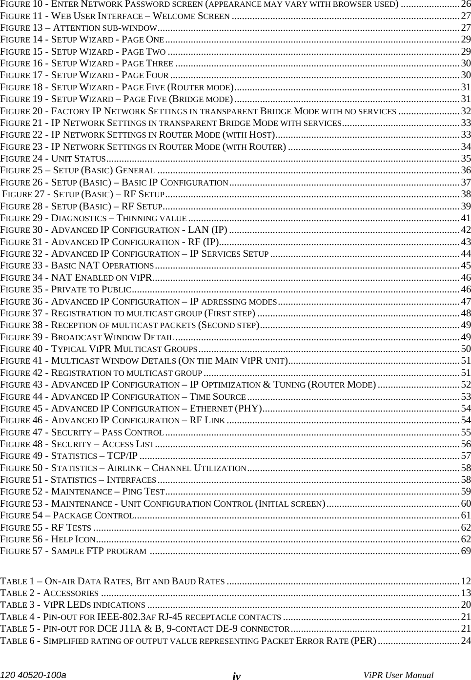

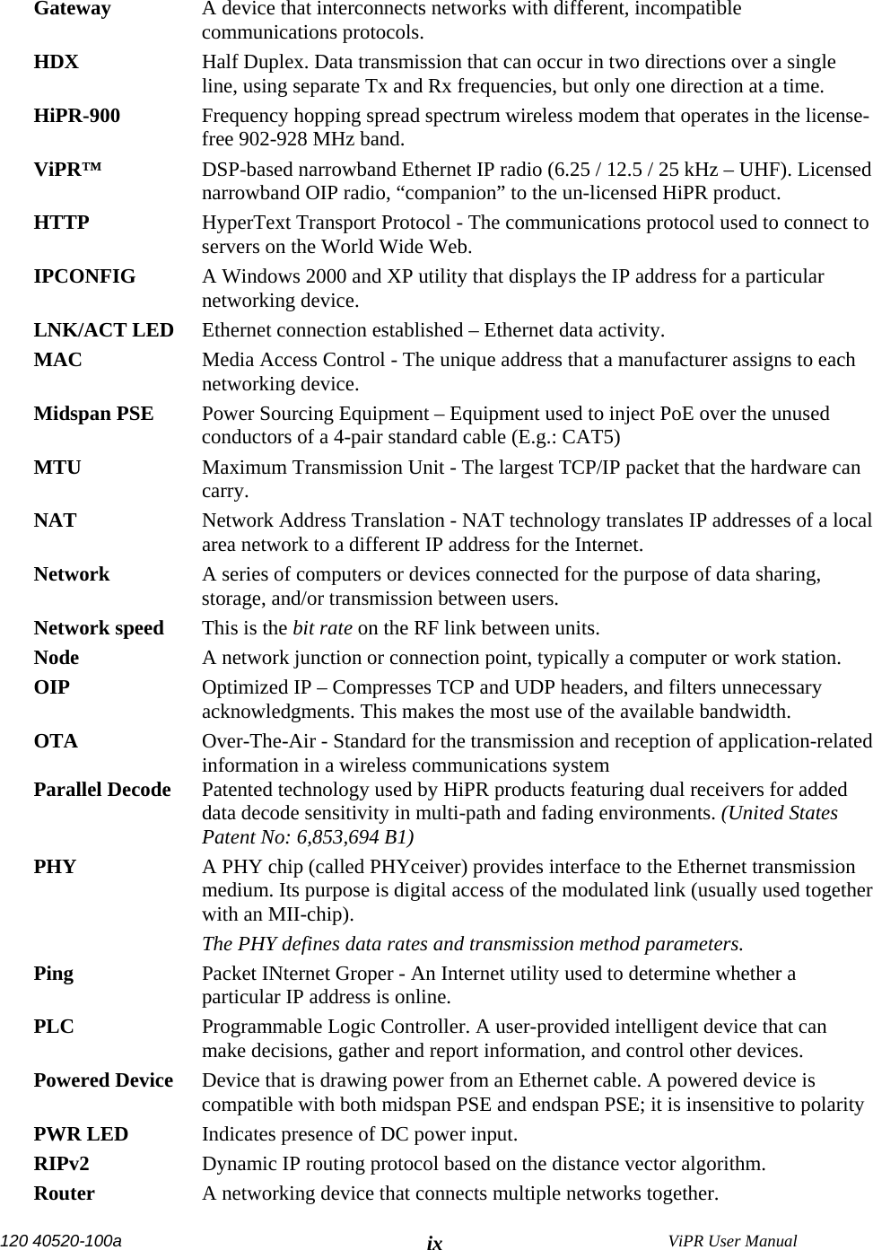
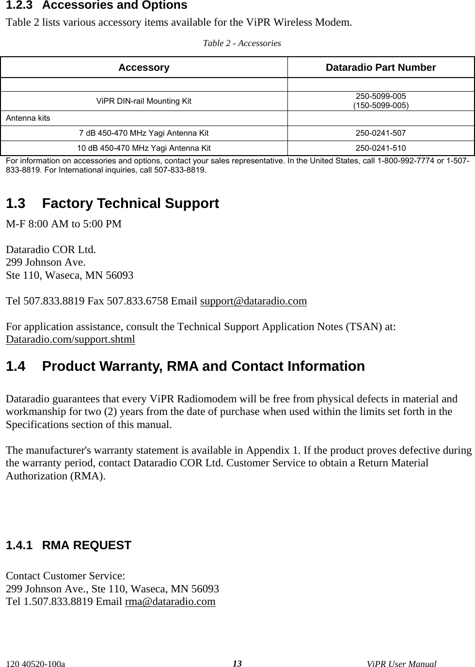
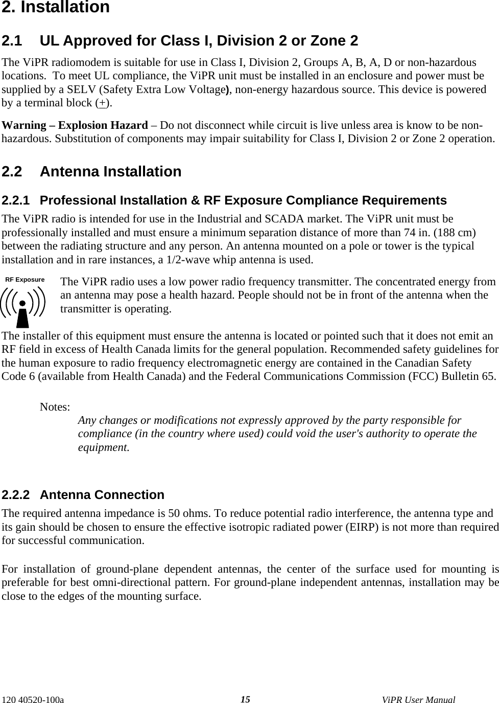
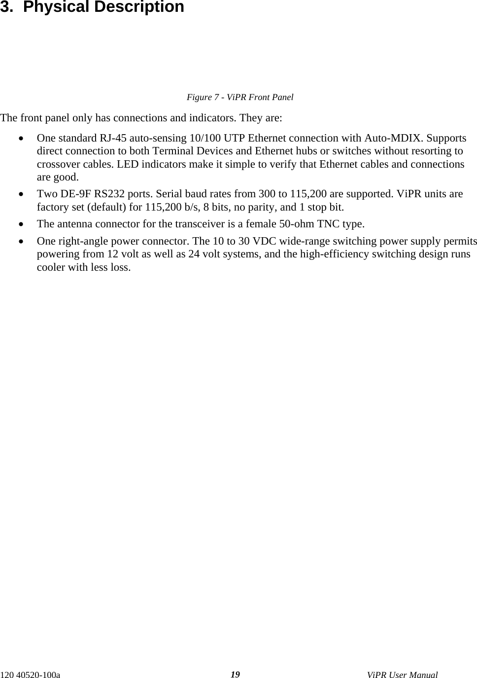
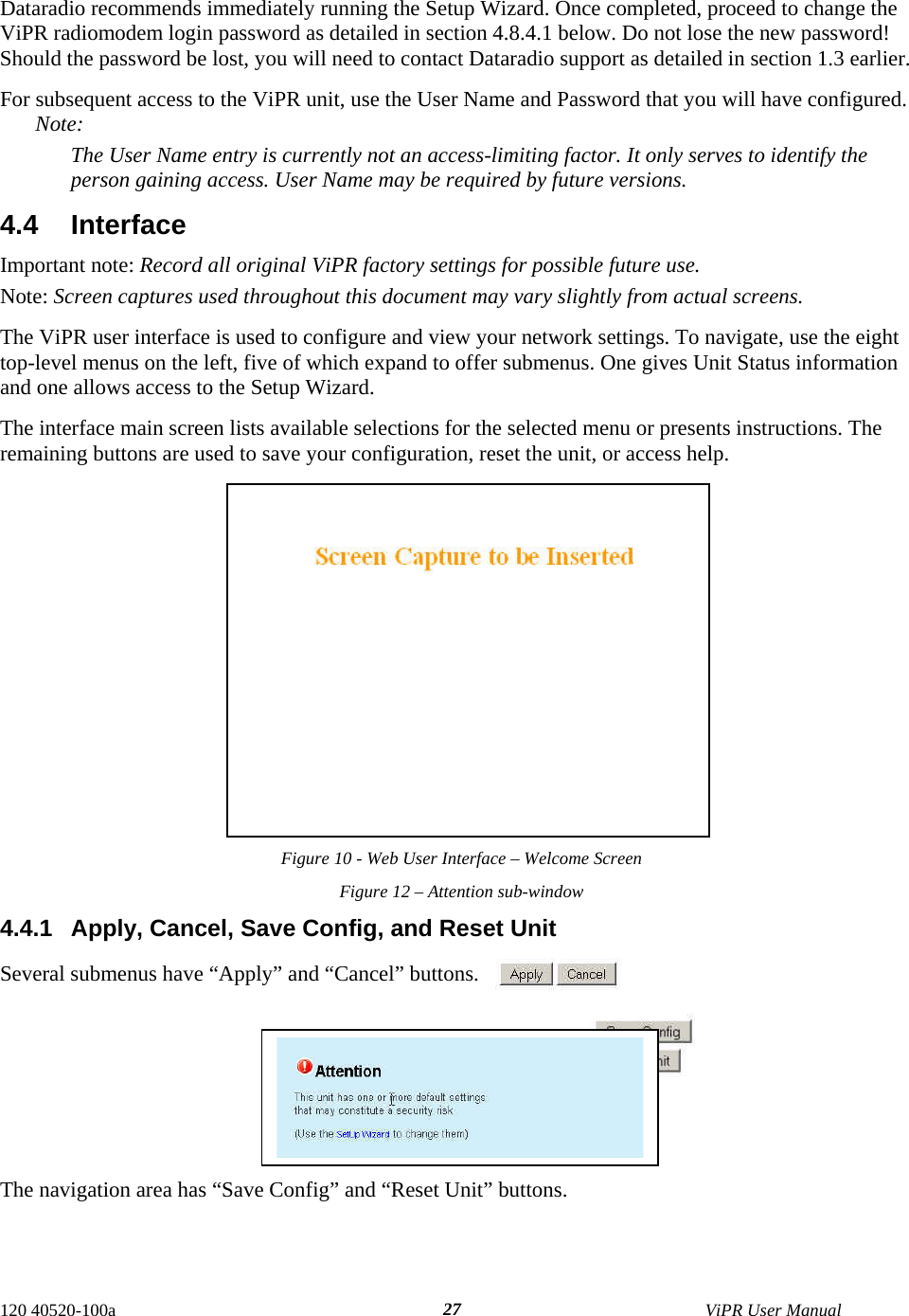
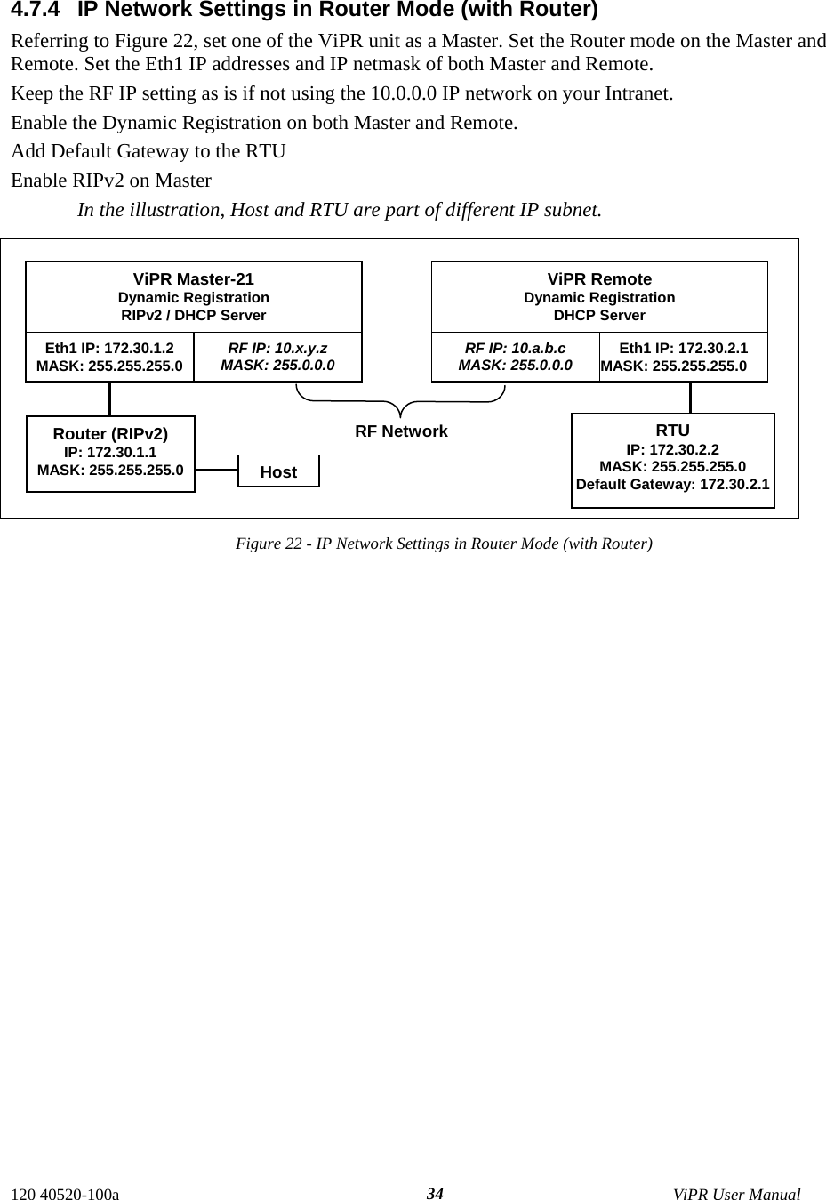
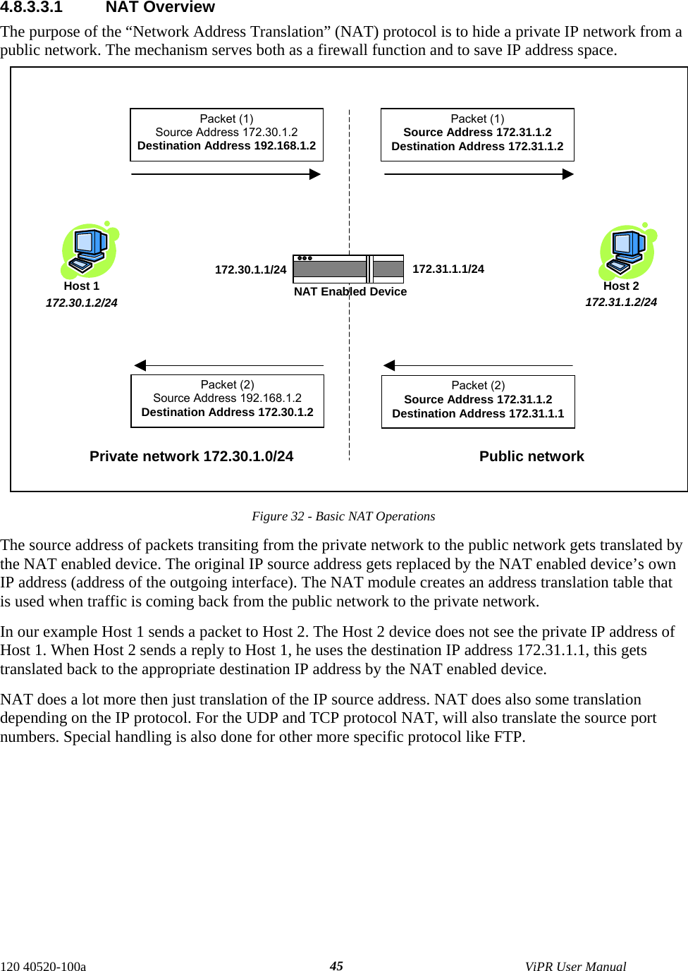
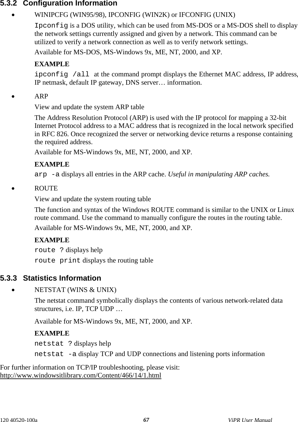
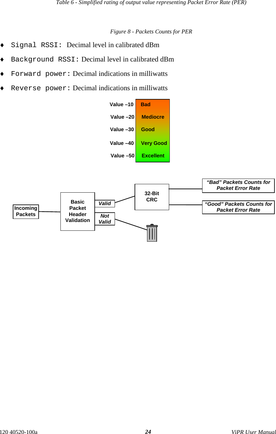
![3.2 Diagnostic Connections The ViPR units continually monitor and report on their environmental and operating conditions. The diagnostic information is in TCP format and is available via any telnet session to port 6272. Transmission of online diagnostics may be enabled or disabled at any station or stations without affecting their ability to communicate with other stations. Diagnostics can be sent anywhere, including being back hauled. Back hauling adds to the network traffic flow and must be taken into account in designing a network. If a return flow is necessary, it needs to be reduced substantially to have a minimal effect on the network as described in section 3.2.1. The ViPR radiomodem can support up to 4 diagnostics socket connections at once. This may be used, for instance, to carry out monitoring at a main office and at up to three separate field locations. It is also possible that one of the four connections use a serial port instead by enabling it on the ViPR’s web browser interface. More information, statistics, and offline test facilities are available via the browser. RF paths can be monitored and checked from either end of a link, without traveling to the other station. 3.2.1 Parameter Adjusting the return diagnostics flow is done via parameter. This parameter indicates that only one out of every x packets delivered will generate an online diagnostic message. The “thinning value” can be adjusted using the web interface (see paragraph 4.8.2.5) and set as follows: ♦ 0 off ♦ 1 every packet delivers a diagnostics message ♦ 1000 every 1000th packet delivers a diagnostic message 3.2.2 Output Format Output format is man / machine-readable, ASCII, comma-delimited format. Reader program used (or written) must decode the “type field” and check for type 0 as more types will be released in future. This will ensure that no changes will be required to the user online diagnostic reader program when the ViPR radio modem gets updated. The fields are: ♦ IP or MAC address: Depends if unit is in Bridge mode or in Router mode • MAC: Hex numbers format [00:01:02:03] • IP: Dotted decimal format [111.222.333.444] ♦ Type of report: Decimal number (n) that identifies the report as a “type n” ♦ # of fields: Decimal number indicating number of comma-delimited fields to follow ♦ Thinning value: Number of data packets before a diagnostic message is delivered ♦ Volts: Decimal indications in decivolts when source is DC input (125 for 12.5V) ♦ Temperature: Decimal internal unit temperature in Celsius degrees ♦ Packet error rate (or PER): 0 or negative decimal value ⎟⎟⎠⎞⎜⎜⎝⎛goodbad10log10 See Figure 8 for details Thus, -51 is CRC error rate of 10-5.1 (since reset or when net stats were cleared). See Table 6. 120 40520-100a ViPR User Manual 23](https://usermanual.wiki/CalAmp-Wireless-Networks/5048-300/User-Guide-802858-Page-23.png)
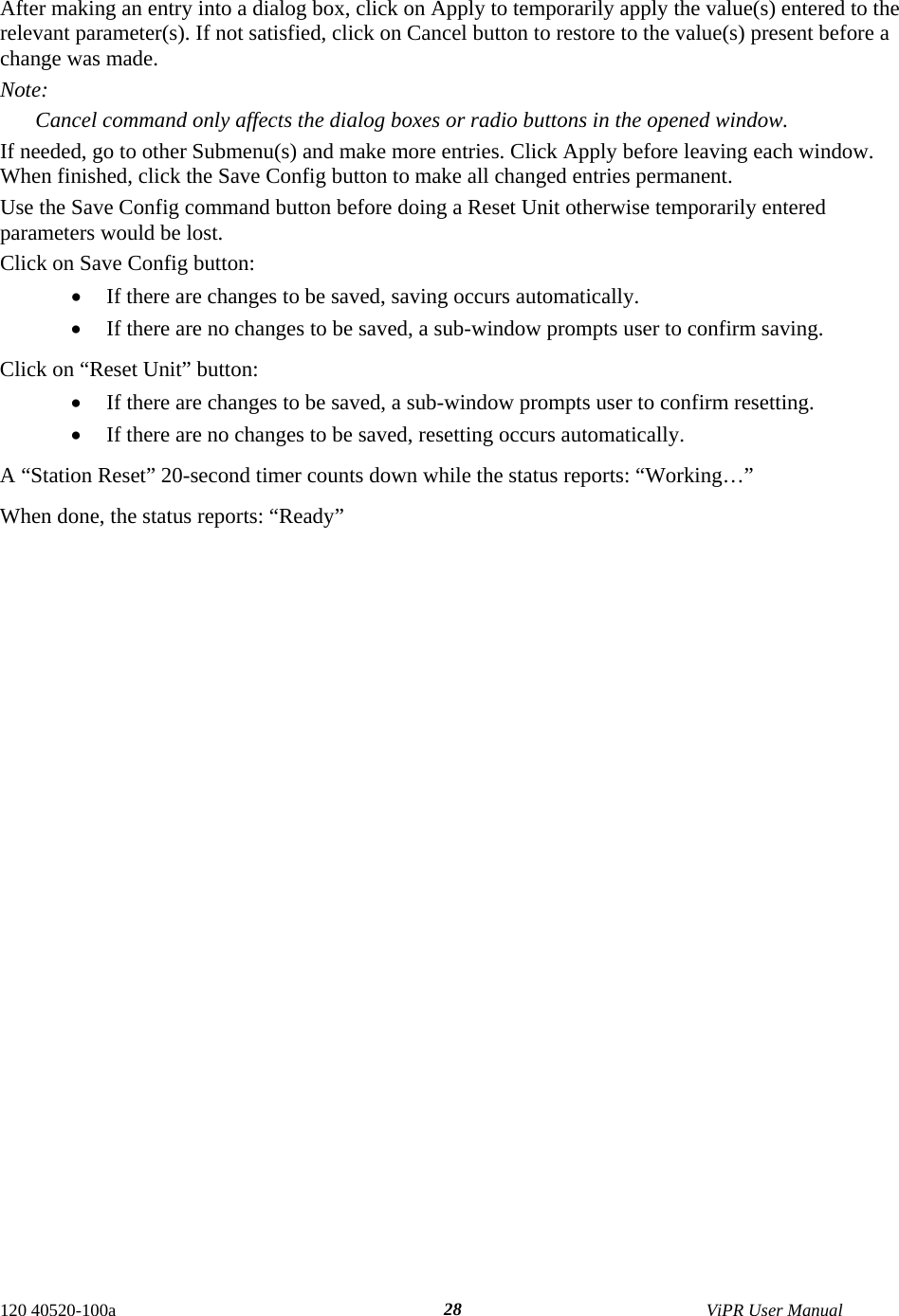
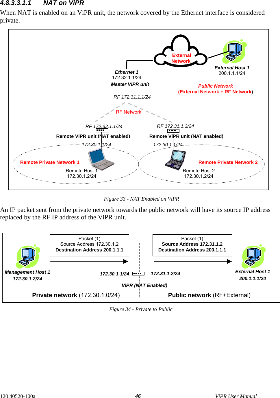
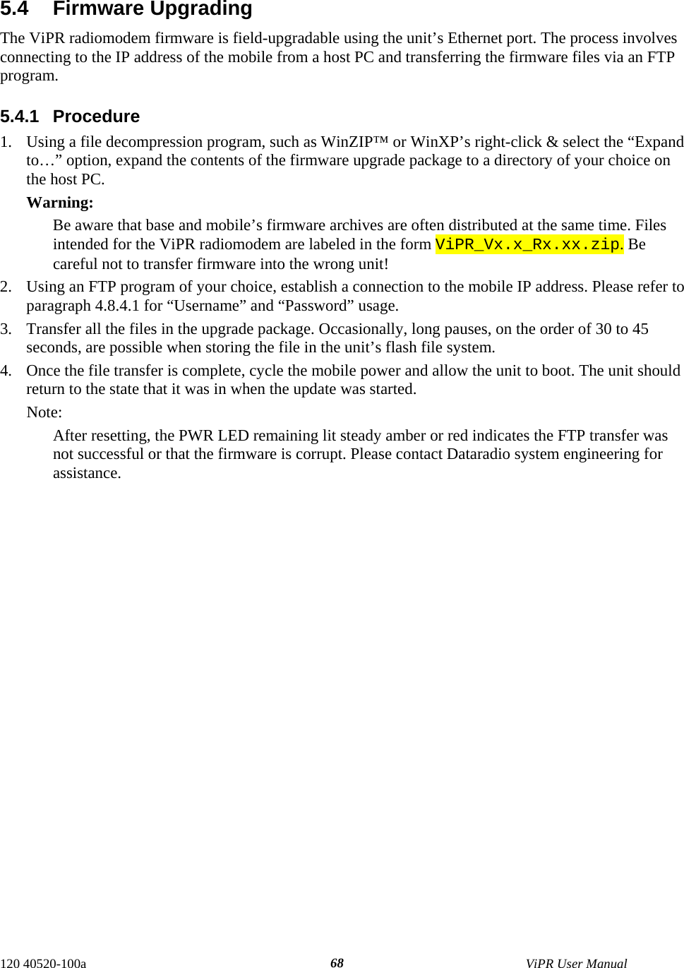
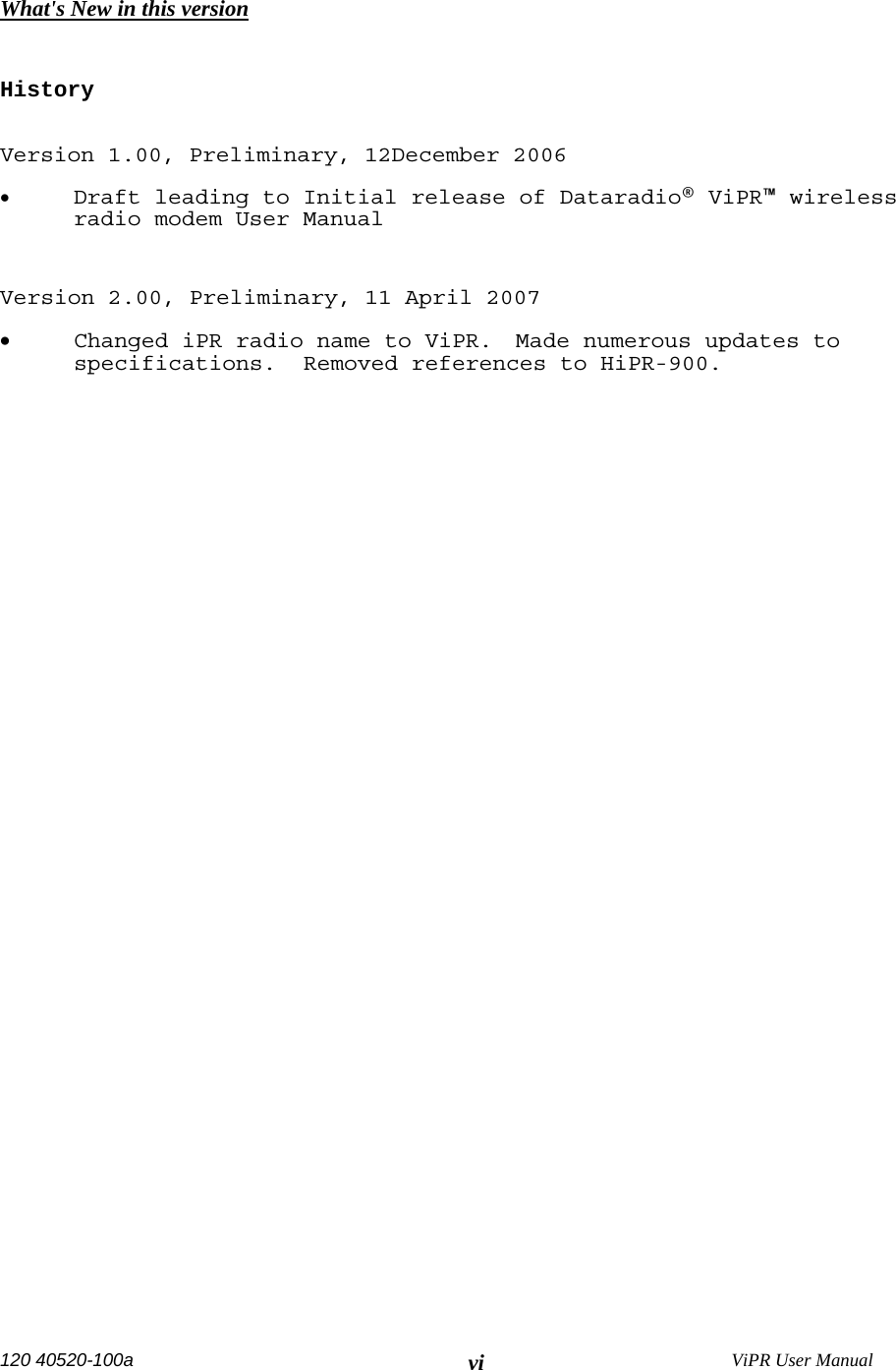
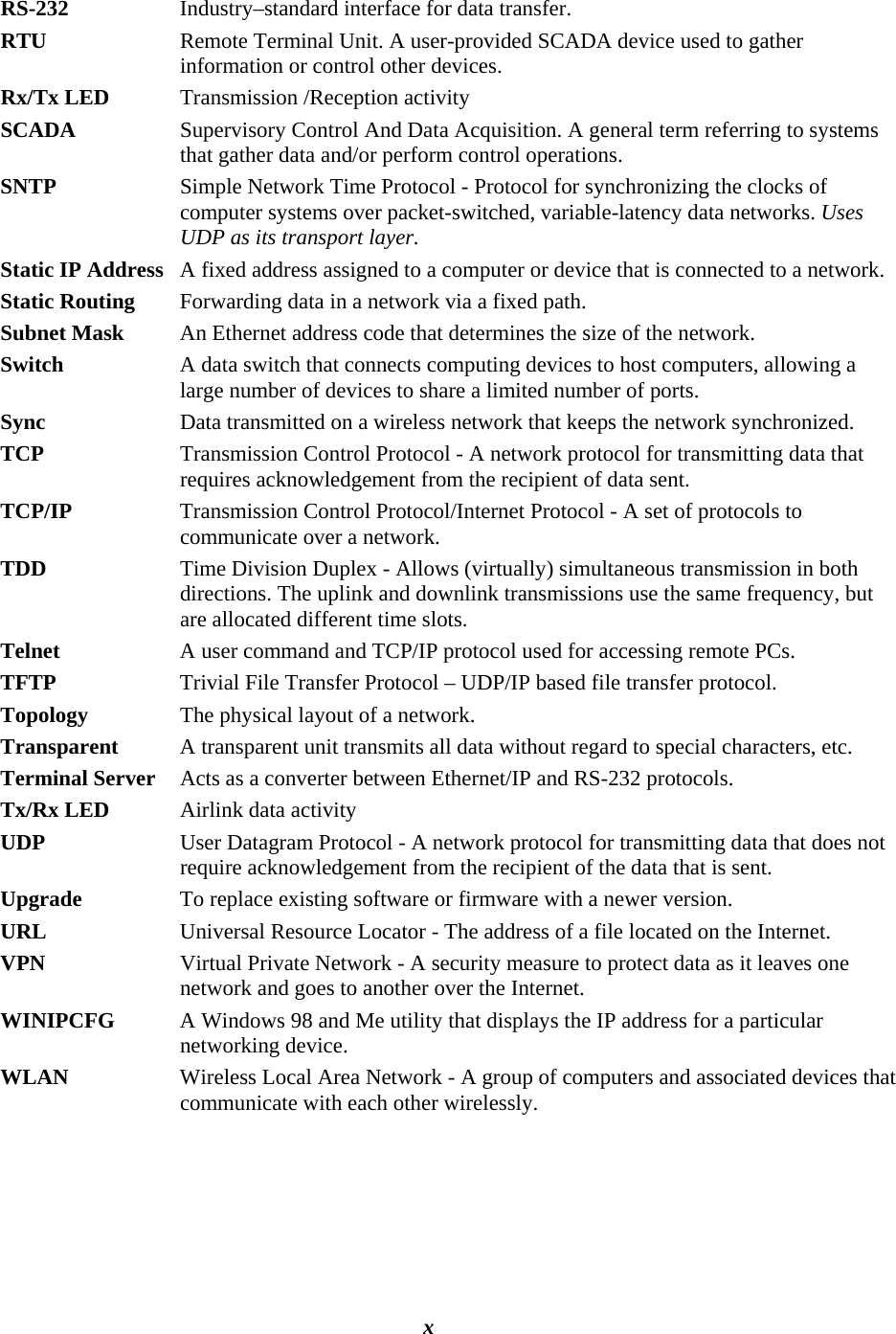
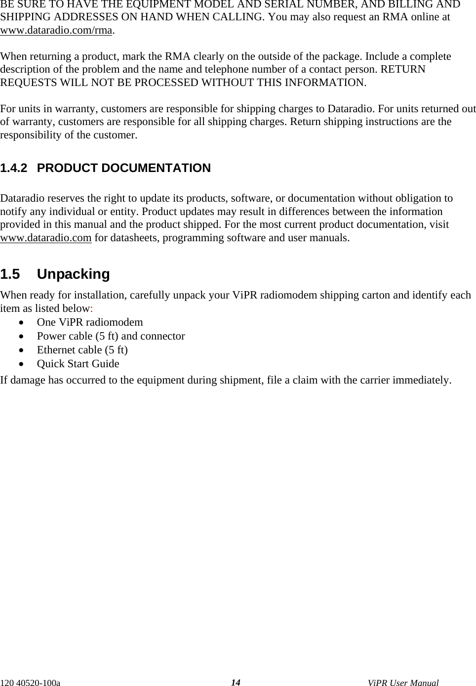
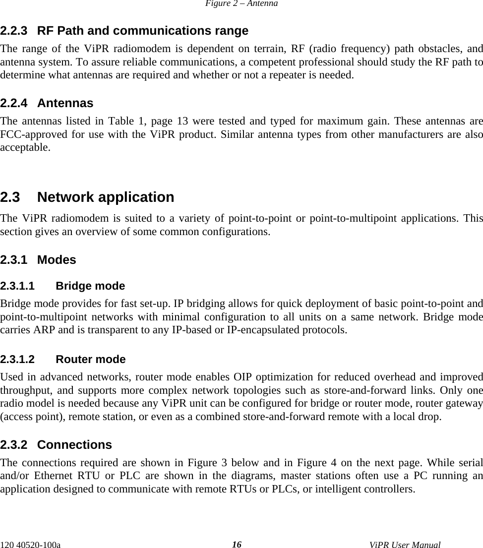
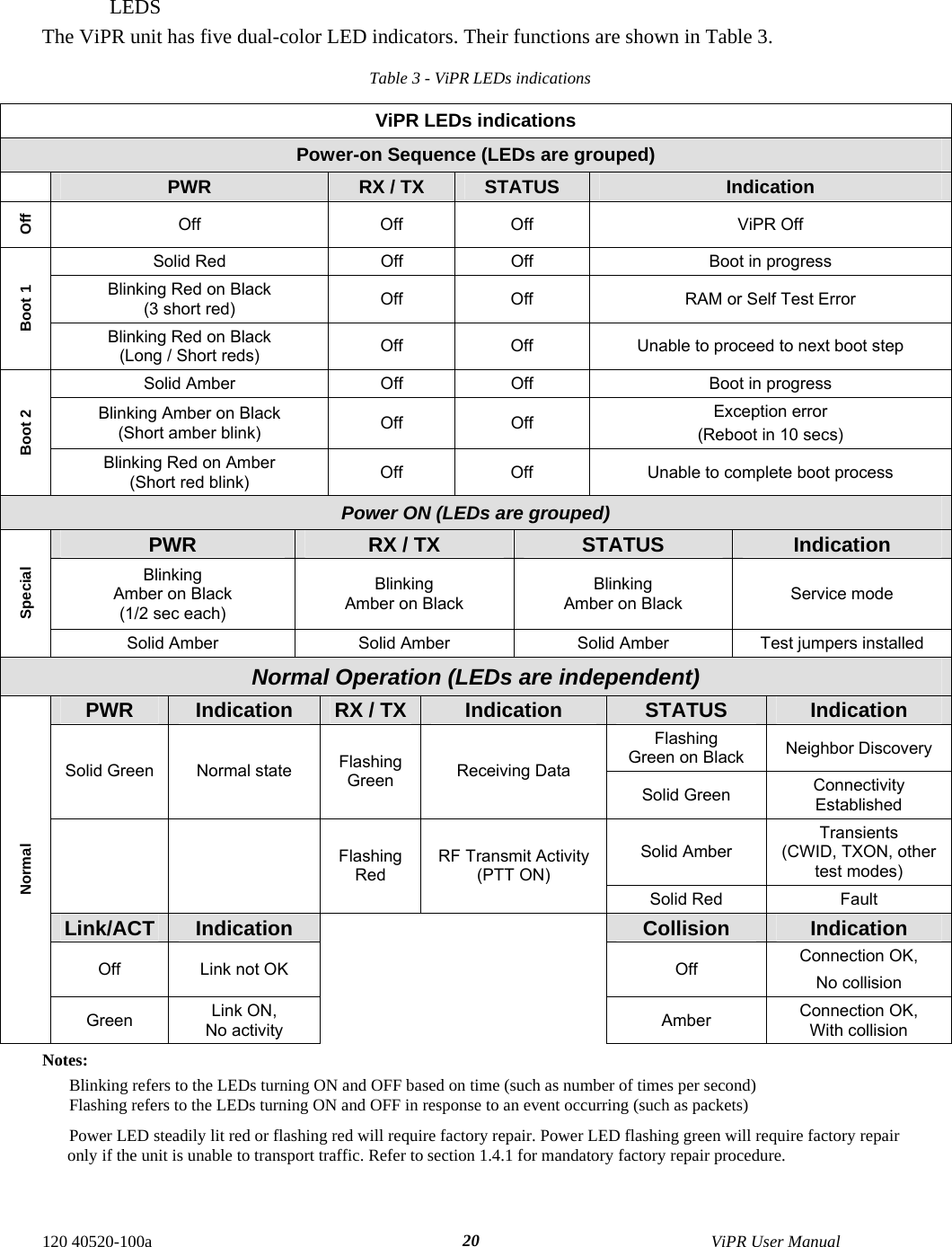
![3.2.2.1 Output Samples From command window, type telnet nnn.nnn.nnn.nnn 6272 and the unit’s diagnostic output will display on screen (where nnn.nnn.nnn.nnn is your unit’s address in dot decimal format) (Thinning value must not be zero). Note: No overhead is generated in the ViPR unit if no online diagnostic connection is actually made. Sample output for bridge mode (no IP address available) [00:00:03:09], 0, 9, 100, 1, 5, 38, -51, -70, -108, 1000, 200 [00:00:03:09], 0, 9, 100, 1, 5, 38, -51, -70, -111, 1000, 200 Sample output for router mode [192.168.36.188], 0, 9, 10, 0, 127, 46, -42, -70, -107, 1000, 200 [192.168.36.204], 0, 9, 10, 0, 103, 42, -53, -70, -110, 1000, 200 Decoding the last line (see Table 7): unit is 192.168.36.204 IP address (in router mode), type of report is 0, there are 9 fields to follow, 1/10 sampled packets are output, DC input is used, Volts are 10.3, Internal temperature is 42°C, PER of 10-5.3, with a carrier level of -70 dBm signal, an average background level of -110dBm, a forward power of 1000 milliwatts (1.0 watt), and a reverse power of 200 milliwatts (0.2 watt). Table 7 – Decoding Sample Output for Router Mode Field # Field Name Sample Output Sample Output Decoded 1 IP address [192.168.36.188] Unit’s IP address is 192.168.36.204 2 Report Type 0 0 3 Number of Fields to Follow 9 9 4 Number of data packets before a diagnostic message is delivered 10 1/10 sampled packets are output 5 Flags 0 DC input 6 Voltage Level 103 10.3 V 7 Internal Temperature 42 42°C 8 PER -53 10-5.39 Signal RSSI -70 -70 dBm 10 Background RSSI -110 -110 dBm 11 Forward power 1000 1000 mW (1.0 Watt) 12 Reverse power 200 200 mW (0.2 Watt) 120 40520-100a ViPR User Manual 25](https://usermanual.wiki/CalAmp-Wireless-Networks/5048-300/User-Guide-802858-Page-25.png)