CalAmp Wireless Networks 5048-300 Wireless Modem User Manual ViPR
CalAmp Wireless Networks Corporation Wireless Modem ViPR
Manual
ViPR
Wireless Radio Modem
User Manual
Preliminary – For Internal Use Only
Copyright DATARADIO Inc.
April 2007
Part no.:
Table of Contents
1. PRODUCT OVERVIEW...............................................................................................................................11
1.1 INTENDED AUDIENCE ....................................................................................................................................11
1.2 GENERAL DESCRIPTION.................................................................................................................................11
1.2.1 Characteristics.....................................................................................................................................12
1.2.2 Configuration.......................................................................................................................................12
1.2.3 Accessories and Options......................................................................................................................13
1.3 FACTORY TECHNICAL SUPPORT ....................................................................................................................13
1.4 PRODUCT WARRANTY, RMA AND CONTACT INFORMATION ........................................................................13
1.4.1 RMA REQUEST...................................................................................................................................13
1.4.2 PRODUCT DOCUMENTATION ........................................................................................................14
1.5 UNPACKING...................................................................................................................................................14
2. INSTALLATION............................................................................................................................................15
2.1 UL APPROVED FOR CLASS I, DIVISION 2 OR ZONE 2.....................................................................................15
2.2 ANTENNA INSTALLATION..............................................................................................................................15
2.2.1 Professional Installation & RF Exposure Compliance Requirements.................................................15
2.2.2 Antenna Connection ............................................................................................................................15
2.2.3 RF Path and communications range ...................................................................................................16
2.2.4 Antennas ..............................................................................................................................................16
2.3 NETWORK APPLICATION................................................................................................................................16
2.3.1 Modes ..................................................................................................................................................16
2.3.1.1 Bridge mode.................................................................................................................................................16
2.3.1.2 Router mode.................................................................................................................................................16
2.3.2 Connections .........................................................................................................................................16
2.4 SELECTABLE DATA RATES ............................................................................................................................17
2.5 POINT TO POINT SYSTEM...............................................................................................................................18
3. PHYSICAL DESCRIPTION.........................................................................................................................19
3.1 LEDS............................................................................................................................................................20
3.2 USER CONNECTOR PIN-OUTS.........................................................................................................................21
3.2.1 Ethernet LAN Port...............................................................................................................................21
3.2.2 SETUP & COM Ports..........................................................................................................................21
3.3 DIAGNOSTIC CONNECTIONS ..........................................................................................................................23
3.3.1 Parameter............................................................................................................................................23
3.3.2 Output Format.....................................................................................................................................23
3.3.2.1 Output Samples............................................................................................................................................25
4. OPERATION & CONFIGURATION..........................................................................................................26
4.1 BROWSER-BASED SETUP AND STATUS ..........................................................................................................26
4.2 LAN SETUP...................................................................................................................................................26
4.3 LOGIN SCREEN ..............................................................................................................................................26
4.3.1 Initial Installation Login......................................................................................................................26
4.4 INTERFACE ....................................................................................................................................................27
4.4.1 Apply, Cancel, Save Config, and Reset Unit........................................................................................27
4.5 SETUP WIZARD (BRIDGE MODE)...................................................................................................................29
4.5.1 Procedure ............................................................................................................................................29
4.6 DEFAULT IP SETTINGS ..................................................................................................................................32
4.6.1 Ethernet Interface................................................................................................................................32
4.6.2 RF Interface.........................................................................................................................................32
4.7 IP NETWORK SETTINGS.................................................................................................................................32
4.7.1 Factory Settings in Bridge Mode.........................................................................................................32
4.7.2 IP Network Settings in Bridge Mode ...................................................................................................33
4.7.3 IP Network Settings in Router Mode (with Host) ................................................................................33
4.7.4 IP Network Settings in Router Mode (with Router).............................................................................34
4.8 ADVANCED IP SETTINGS...............................................................................................................................35
120 40520-100a ViPR User Manual
ii
4.8.1 Unit Status ...........................................................................................................................................35
4.8.2 Setup (Basic)........................................................................................................................................36
4.8.2.1 Setup (General)............................................................................................................................................36
4.8.2.2 Basic IP Configuration.................................................................................................................................37
4.8.2.3 RF Setup ......................................................................................................................................................38
4.8.2.4 Serial Ports Setup.........................................................................................................................................39
4.8.2.5 Diagnostics...................................................................................................................................................41
4.8.3 Setup (Advanced).................................................................................................................................42
4.8.3.1 LAN (IP)......................................................................................................................................................42
4.8.3.2 RF (IP) .........................................................................................................................................................43
4.8.3.3 IP Services Setup .........................................................................................................................................44
4.8.3.3.1 NAT Overview........................................................................................................................................45
4.8.3.4 IP addressing modes ....................................................................................................................................47
4.8.3.4.1 IP Broadcast/Multicast Overview ...........................................................................................................48
4.8.3.5 IP Optimization & Tuning ...........................................................................................................................52
4.8.3.6 Time Source.................................................................................................................................................53
4.8.3.7 Ethernet (PHY) ............................................................................................................................................54
4.8.3.8 RF Link........................................................................................................................................................54
4.8.4 Security................................................................................................................................................55
4.8.4.1 Pass Control.................................................................................................................................................55
4.8.4.2 Access List...................................................................................................................................................56
4.8.5 Statistics...............................................................................................................................................57
4.8.5.1 TCP/IP .........................................................................................................................................................57
4.8.5.2 AirLink ........................................................................................................................................................58
4.8.5.3 Interfaces......................................................................................................................................................58
4.8.6 Maintenance ........................................................................................................................................59
4.8.6.1 Ping Test......................................................................................................................................................59
4.8.6.2 Unit Configuration Control..........................................................................................................................60
4.8.6.3 Package Control...........................................................................................................................................61
4.8.7 Radio - RF Tests ..................................................................................................................................62
4.8.8 Help .....................................................................................................................................................62
5. OPTIMIZATION & TROUBLESHOOTING.............................................................................................63
5.1 MAXIMIZING TCP/IP.....................................................................................................................................65
5.2 MAXIMIZING VIA SETUP PAGES.....................................................................................................................65
5.2.1 Use Router Mode.................................................................................................................................65
5.2.2 Reduce RF MTU size ............................................................................. Error! Bookmark not defined.
5.2.3 Reduce RF network bit rate.................................................................................................................65
5.2.4 Increase OIP Retries Limit..................................................................................................................66
5.3 TROUBLESHOOTING TOOLS ...........................................................................................................................66
5.3.1 Network Connectivity...........................................................................................................................66
5.3.2 Configuration Information ..................................................................................................................67
5.3.3 Statistics Information...........................................................................................................................67
5.4 FIRMWARE UPGRADING ................................................................................................................................68
5.4.1 Procedure ............................................................................................................................................68
5.4.1.1 File Integrity Failure....................................................................................................................................69
6. SPECIFICATIONS ........................................................................................................................................70
FIGURE 1 – VIPR – TO BE UPDATED WHEN AVAILABLE..............................................................................................11
FIGURE 3 – ANTENNA ................................................................................................................................................16
FIGURE 4 - BASIC SETUP ............................................................................................................................................17
FIGURE 5 - SETUP USING SWITCH (OR HUB) AND POE POWER INJECTOR....................................................................17
FIGURE 6 - POINT-TO-POINT IP NETWORK SYSTEM ...................................................................................................18
FIGURE 7 - POINT-TO-MULTIPOINT SYSTEM...............................................................................................................18
FIGURE 8 - VIPR FRONT PANEL.................................................................................................................................19
FIGURE 9 - PACKETS COUNTS FOR PER .....................................................................................................................24
120 40520-100a ViPR User Manual
iii
FIGURE 10 - ENTER NETWORK PASSWORD SCREEN (APPEARANCE MAY VARY WITH BROWSER USED) .......................26
FIGURE 11 - WEB USER INTERFACE – WELCOME SCREEN .........................................................................................27
FIGURE 13 – ATTENTION SUB-WINDOW......................................................................................................................27
FIGURE 14 - SETUP WIZARD - PAGE ONE...................................................................................................................29
FIGURE 15 - SETUP WIZARD - PAGE TWO ..................................................................................................................29
FIGURE 16 - SETUP WIZARD - PAGE THREE ...............................................................................................................30
FIGURE 17 - SETUP WIZARD - PAGE FOUR .................................................................................................................30
FIGURE 18 - SETUP WIZARD - PAGE FIVE (ROUTER MODE)........................................................................................31
FIGURE 19 - SETUP WIZARD – PAGE FIVE (BRIDGE MODE)........................................................................................31
FIGURE 20 - FACTORY IP NETWORK SETTINGS IN TRANSPARENT BRIDGE MODE WITH NO SERVICES ........................32
FIGURE 21 - IP NETWORK SETTINGS IN TRANSPARENT BRIDGE MODE WITH SERVICES..............................................33
FIGURE 22 - IP NETWORK SETTINGS IN ROUTER MODE (WITH HOST)........................................................................33
FIGURE 23 - IP NETWORK SETTINGS IN ROUTER MODE (WITH ROUTER) ...................................................................34
FIGURE 24 - UNIT STATUS..........................................................................................................................................35
FIGURE 25 – SETUP (BASIC) GENERAL ......................................................................................................................36
FIGURE 26 - SETUP (BASIC) – BASIC IP CONFIGURATION..........................................................................................37
FIGURE 27 - SETUP (BASIC) – RF SETUP...................................................................................................................38
FIGURE 28 - SETUP (BASIC) – RF SETUP....................................................................................................................39
FIGURE 29 - DIAGNOSTICS – THINNING VALUE..........................................................................................................41
FIGURE 30 - ADVANCED IP CONFIGURATION - LAN (IP) ..........................................................................................42
FIGURE 31 - ADVANCED IP CONFIGURATION - RF (IP)..............................................................................................43
FIGURE 32 - ADVANCED IP CONFIGURATION – IP SERVICES SETUP ..........................................................................44
FIGURE 33 - BASIC NAT OPERATIONS.......................................................................................................................45
FIGURE 34 - NAT ENABLED ON VIPR........................................................................................................................46
FIGURE 35 - PRIVATE TO PUBLIC................................................................................................................................46
FIGURE 36 - ADVANCED IP CONFIGURATION – IP ADRESSING MODES.......................................................................47
FIGURE 37 - REGISTRATION TO MULTICAST GROUP (FIRST STEP) ...............................................................................48
FIGURE 38 - RECEPTION OF MULTICAST PACKETS (SECOND STEP)..............................................................................49
FIGURE 39 - BROADCAST WINDOW DETAIL...............................................................................................................49
FIGURE 40 - TYPICAL VIPR MULTICAST GROUPS......................................................................................................50
FIGURE 41 - MULTICAST WINDOW DETAILS (ON THE MAIN VIPR UNIT)...................................................................51
FIGURE 42 - REGISTRATION TO MULTICAST GROUP....................................................................................................51
FIGURE 43 - ADVANCED IP CONFIGURATION – IP OPTIMIZATION & TUNING (ROUTER MODE)................................52
FIGURE 44 - ADVANCED IP CONFIGURATION – TIME SOURCE...................................................................................53
FIGURE 45 - ADVANCED IP CONFIGURATION – ETHERNET (PHY).............................................................................54
FIGURE 46 - ADVANCED IP CONFIGURATION – RF LINK...........................................................................................54
FIGURE 47 - SECURITY – PASS CONTROL...................................................................................................................55
FIGURE 48 - SECURITY – ACCESS LIST.......................................................................................................................56
FIGURE 49 - STATISTICS – TCP/IP .............................................................................................................................57
FIGURE 50 - STATISTICS – AIRLINK – CHANNEL UTILIZATION...................................................................................58
FIGURE 51 - STATISTICS – INTERFACES......................................................................................................................58
FIGURE 52 - MAINTENANCE – PING TEST...................................................................................................................59
FIGURE 53 - MAINTENANCE - UNIT CONFIGURATION CONTROL (INITIAL SCREEN)....................................................60
FIGURE 54 – PACKAGE CONTROL...............................................................................................................................61
FIGURE 55 - RF TESTS ...............................................................................................................................................62
FIGURE 56 - HELP ICON..............................................................................................................................................62
FIGURE 57 - SAMPLE FTP PROGRAM .........................................................................................................................69
TABLE 1 – ON-AIR DATA RATES, BIT AND BAUD RATES ...........................................................................................12
TABLE 2 - ACCESSORIES ............................................................................................................................................13
TABLE 3 - VIPR LEDS INDICATIONS ..........................................................................................................................20
TABLE 4 - PIN-OUT FOR IEEE-802.3AF RJ-45 RECEPTACLE CONTACTS .....................................................................21
TABLE 5 - PIN-OUT FOR DCE J11A & B, 9-CONTACT DE-9 CONNECTOR..................................................................21
TABLE 6 - SIMPLIFIED RATING OF OUTPUT VALUE REPRESENTING PACKET ERROR RATE (PER)................................24
120 40520-100a ViPR User Manual
iv
TABLE 7 – DECODING SAMPLE OUTPUT FOR ROUTER MODE .....................................................................................25
APPENDIX 1 - DATA TELEMETRY WARRANTY ...........................................................................................................72
120 40520-100a ViPR User Manual
v

What's New in this version
History
Version 1.00, Preliminary, 12December 2006
• Draft leading to Initial release of Dataradio® ViPR™ wireless
radio modem User Manual
Version 2.00, Preliminary, 11 April 2007
• Changed iPR radio name to ViPR. Made numerous updates to
specifications. Removed references to HiPR-900.
120 40520-100a ViPR User Manual
vi
About Dataradio
Dataradio is a leading designer and manufacturer of advanced wireless data products and systems for
mission critical applications. Our products are found at the heart of mobile data and SCADA networks
around the world.
With over 25 years dedicated to data technology and innovation, Dataradio is the premier source for
wireless data solutions. Our products include mobile data products, telemetry devices, integrated wireless
modems for fixed point-to-point and point to multi-point applications, and OEMs. Our product line is one
of the broadest in the industry covering the most often-used frequency bands.
Dataradio COR Ltd.
Dataradio COR Ltd. designs and manufactures radios and integrated wireless modems to serve a wide
variety of data communication needs. Dataradio produces equipment for the fixed data market including
SCADA systems for utilities, petrochemical, waste and fresh water management markets and RF boards
for OEM applications in the Radio Frequency Data Capture market.
Product Warranty
The manufacturer's warranty statement for this product is available in Appendix 1.
www.dataradio.com
Dataradio provides product brochures, case studies, software downloads, and product information on our
website. Every effort is taken to provide accurate, timely product information in this user manual.
Product updates may result in differences between the information provided herein and the product
shipped. The information in this document is subject to change without notice.
DATARADIO is a registered trademark, ViPR and TRUSTED WIRELESS DATA are trademarks of Dataradio Inc
120 40520-100a ViPR User Manual
vii

Definitions
Item Definition
Access Point Communication hub for users to connect to a LAN. Access Points are important
for providing heightened wireless security and for extending the physical range
of service a wireless user has access to.
AES Advanced Encryption Standard (AES)
Airlink Physical radio frequency connections used for communications between units.
ARP Address Resolution Protocol – Maps Internet address to physical address.
Backbone The part of a network that connects most of the systems and networks together,
and handles the most data.
Bandwidth The transmission capacity of a given device or network.
Browser An application program that provides a way to look at and interact with all the
information on the World Wide Web.
Collision LED Connection is established but collisions are occurring.
COM Port Both RS-232 serial communications ports of the ViPR wireless radio modem are
configured as DCE and are designed to connect directly to a DTE.
Default Gateway A device that forwards Internet traffic from your local area network.
DCE Data Communications Equipment. This designation is applied to equipment such
as modems. DCE is designed to connect to DTE.
DHCP Dynamic Host Configuration Protocol - A networking protocol that allows
administrators to assign temporary IP addresses to network computers by
"leasing" an IP address to a user for a limited amount of time, instead of
assigning permanent IP addresses.
DNS Domain Name Server - translates the domain name into an IP address.
Domain A specific name for a network of computers.
DTE Data Terminal Equipment. This designation is applied to equipment such as
terminals, PCs, RTUs, PLCs, etc. DTE is designed to connect to DCE.
Dynamic IP Addr A temporary IP address assigned by a DHCP server.
Ethernet IEEE standard network protocol that specifies how data is placed on and
retrieved from a common transmission medium.
Endspan PSE Power Sourcing Equipment – Equipment used to inject PoE over the unused
conductors, over the data baring conductor, or over both types of conductors of a
4-pair standard cable (E.g: CAT5).
Firewall A set of related programs located at a network gateway server that protects the
resources of a network from users from other networks.
Firmware The programming code that runs a networking device.
Fragmentation Breaking a packet into smaller units when transmitting over a network medium
that cannot support the original size of the packet.
FTP File Transfer Protocol - A protocol used to transfer files over a TCP/IP network.
120 40520-100a ViPR User Manual
viii
Gateway A device that interconnects networks with different, incompatible
communications protocols.
HDX Half Duplex. Data transmission that can occur in two directions over a single
line, using separate Tx and Rx frequencies, but only one direction at a time.
HiPR-900 Frequency hopping spread spectrum wireless modem that operates in the license-
free 902-928 MHz band.
ViPR™ DSP-based narrowband Ethernet IP radio (6.25 / 12.5 / 25 kHz – UHF). Licensed
narrowband OIP radio, “companion” to the un-licensed HiPR product.
HTTP HyperText Transport Protocol - The communications protocol used to connect to
servers on the World Wide Web.
IPCONFIG A Windows 2000 and XP utility that displays the IP address for a particular
networking device.
LNK/ACT LED Ethernet connection established – Ethernet data activity.
MAC Media Access Control - The unique address that a manufacturer assigns to each
networking device.
Midspan PSE Power Sourcing Equipment – Equipment used to inject PoE over the unused
conductors of a 4-pair standard cable (E.g.: CAT5)
MTU Maximum Transmission Unit - The largest TCP/IP packet that the hardware can
carry.
NAT Network Address Translation - NAT technology translates IP addresses of a local
area network to a different IP address for the Internet.
Network A series of computers or devices connected for the purpose of data sharing,
storage, and/or transmission between users.
Network speed This is the bit rate on the RF link between units.
Node A network junction or connection point, typically a computer or work station.
OIP Optimized IP – Compresses TCP and UDP headers, and filters unnecessary
acknowledgments. This makes the most use of the available bandwidth.
OTA Over-The-Air - Standard for the transmission and reception of application-related
information in a wireless communications system
Parallel Decode Patented technology used by HiPR products featuring dual receivers for added
data decode sensitivity in multi-path and fading environments. (United States
Patent No: 6,853,694 B1)
PHY A PHY chip (called PHYceiver) provides interface to the Ethernet transmission
medium. Its purpose is digital access of the modulated link (usually used together
with an MII-chip).
The PHY defines data rates and transmission method parameters.
Ping Packet INternet Groper - An Internet utility used to determine whether a
particular IP address is online.
PLC Programmable Logic Controller. A user-provided intelligent device that can
make decisions, gather and report information, and control other devices.
Powered Device Device that is drawing power from an Ethernet cable. A powered device is
compatible with both midspan PSE and endspan PSE; it is insensitive to polarity
PWR LED Indicates presence of DC power input.
RIPv2 Dynamic IP routing protocol based on the distance vector algorithm.
Router A networking device that connects multiple networks together.
120 40520-100a ViPR User Manual
ix
RS-232 Industry–standard interface for data transfer.
RTU Remote Terminal Unit. A user-provided SCADA device used to gather
information or control other devices.
Rx/Tx LED Transmission /Reception activity
SCADA Supervisory Control And Data Acquisition. A general term referring to systems
that gather data and/or perform control operations.
SNTP Simple Network Time Protocol - Protocol for synchronizing the clocks of
computer systems over packet-switched, variable-latency data networks. Uses
UDP as its transport layer.
Static IP Address A fixed address assigned to a computer or device that is connected to a network.
Static Routing Forwarding data in a network via a fixed path.
Subnet Mask An Ethernet address code that determines the size of the network.
Switch A data switch that connects computing devices to host computers, allowing a
large number of devices to share a limited number of ports.
Sync Data transmitted on a wireless network that keeps the network synchronized.
TCP Transmission Control Protocol - A network protocol for transmitting data that
requires acknowledgement from the recipient of data sent.
TCP/IP Transmission Control Protocol/Internet Protocol - A set of protocols to
communicate over a network.
TDD Time Division Duplex - Allows (virtually) simultaneous transmission in both
directions. The uplink and downlink transmissions use the same frequency, but
are allocated different time slots.
Telnet A user command and TCP/IP protocol used for accessing remote PCs.
TFTP Trivial File Transfer Protocol – UDP/IP based file transfer protocol.
Topology The physical layout of a network.
Transparent A transparent unit transmits all data without regard to special characters, etc.
Terminal Server Acts as a converter between Ethernet/IP and RS-232 protocols.
Tx/Rx LED Airlink data activity
UDP User Datagram Protocol - A network protocol for transmitting data that does not
require acknowledgement from the recipient of the data that is sent.
Upgrade To replace existing software or firmware with a newer version.
URL Universal Resource Locator - The address of a file located on the Internet.
VPN Virtual Private Network - A security measure to protect data as it leaves one
network and goes to another over the Internet.
WINIPCFG A Windows 98 and Me utility that displays the IP address for a particular
networking device.
WLAN Wireless Local Area Network - A group of computers and associated devices that
communicate with each other wirelessly.
120 40520-100a ViPR User Manual
x
1. Product Overview
This document provides information required for the operation and verification of the DATARADIO®
ViPR narrowband Ethernet IP radiomodem.
1.1 Intended Audience
This manual is intended for system designers, professional installers, and maintenance technicians.
1.2 General Description
Dataradio’s ViPR radiomodem is a DSP-based narrowband Ethernet IP radio that operates in the UHF
(406.1-512 MHz) frequency ranges.
The ViPR radiomodem is designed for SCADA, telemetry, control, and industrial applications in Point-
to-Point and Point-to-Multipoint configurations.
The ViPR radiomodem supports serial and Ethernet/IP Remote Terminal Units (RTU) and programmable
logic controllers (PLC). It is standard IEEE 802.3af compliant.
The ViPR wireless modem consists of two logic PCBs; one that includes the modem circuitry and the
other the radio module. Both are installed in a cast aluminum case.
The unit is not hermetically sealed and should be mounted in a suitable enclosure when dust and/or a
corrosive atmosphere are anticipated. There are no external switches or adjustments; all operating
parameters are set via a web browser.
Figure 1 – ViPR – to be updated when available
120 40520-100a ViPR User Manual
11

1.2.1 Characteristics
The ViPR product has the following operational characteristics:
• An ViPR RF deck, frequency range of 406.1-470 MHz and 450-512 MHz.
• High-speed user-selectable data rates of up to 32 Kbps in full channel, 16 Kbps in half channel, and 8
Kbps in quarter channel.
• Built-in transceiver adjustable to 10 watts.
• Used as an access point or an end point with each configurable in:
♦ Bridge mode – for quick setup of units on same network
♦ Router mode - for advanced networks
• Embedded web server to access status and/or setup information.
• Remote access for over-the-air system firmware upgrades.
• Wide input power range of 10 to 30 volts DC
• AES 128-bit data encryption
• Superior data compression
• Native UDP and TCP/IP support
• Optimized IP (OIP) protocol reduction
• Diagnostics
• Supports up to 32 different frequency channel pairs
• SNMP for first-level service by non IT personnel
• RF diagnostics
• Store/Forward feature
Table 1 – On-air Data Rates, Bit and Baud Rates
Quarter Channel
Channel spacing
6.25 kHz
Half Channel
Channel spacing
12.5 kHz
Full Channel
Channel Spacing
25 kHz
Bit Rates 4-8 kb/s 8 - 16 kb/s 16 – 32 kb/s
Baud Rates 4 kHz 8 kHz 16 kHz
1.2.2 Configuration
The ViPR units are factory-configured to default settings. Configuration changes or upgrades are web
browser-based.
120 40520-100a ViPR User Manual
12

1.2.3 Accessories and Options
Table 2 lists various accessory items available for the ViPR Wireless Modem.
Table 2 - Accessories
Accessory Dataradio Part Number
ViPR DIN-rail Mounting Kit 250-5099-005
(150-5099-005)
Antenna kits
7 dB 450-470 MHz Yagi Antenna Kit 250-0241-507
10 dB 450-470 MHz Yagi Antenna Kit 250-0241-510
For information on accessories and options, contact your sales representative. In the United States, call 1-800-992-7774 or 1-507-
833-8819. For International inquiries, call 507-833-8819.
1.3 Factory Technical Support
M-F 8:00 AM to 5:00 PM
Dataradio COR Ltd.
299 Johnson Ave.
Ste 110, Waseca, MN 56093
Tel 507.833.8819 Fax 507.833.6758 Email support@dataradio.com
For application assistance, consult the Technical Support Application Notes (TSAN) at:
Dataradio.com/support.shtml
1.4 Product Warranty, RMA and Contact Information
Dataradio guarantees that every ViPR Radiomodem will be free from physical defects in material and
workmanship for two (2) years from the date of purchase when used within the limits set forth in the
Specifications section of this manual.
The manufacturer's warranty statement is available in Appendix 1. If the product proves defective during
the warranty period, contact Dataradio COR Ltd. Customer Service to obtain a Return Material
Authorization (RMA).
1.4.1 RMA REQUEST
Contact Customer Service:
299 Johnson Ave., Ste 110, Waseca, MN 56093
Tel 1.507.833.8819 Email rma@dataradio.com
120 40520-100a ViPR User Manual
13

BE SURE TO HAVE THE EQUIPMENT MODEL AND SERIAL NUMBER, AND BILLING AND
SHIPPING ADDRESSES ON HAND WHEN CALLING. You may also request an RMA online at
www.dataradio.com/rma.
When returning a product, mark the RMA clearly on the outside of the package. Include a complete
description of the problem and the name and telephone number of a contact person. RETURN
REQUESTS WILL NOT BE PROCESSED WITHOUT THIS INFORMATION.
For units in warranty, customers are responsible for shipping charges to Dataradio. For units returned out
of warranty, customers are responsible for all shipping charges. Return shipping instructions are the
responsibility of the customer.
1.4.2 PRODUCT DOCUMENTATION
Dataradio reserves the right to update its products, software, or documentation without obligation to
notify any individual or entity. Product updates may result in differences between the information
provided in this manual and the product shipped. For the most current product documentation, visit
www.dataradio.com for datasheets, programming software and user manuals.
1.5 Unpacking
When ready for installation, carefully unpack your ViPR radiomodem shipping carton and identify each
item as listed below:
• One ViPR radiomodem
• Power cable (5 ft) and connector
• Ethernet cable (5 ft)
• Quick Start Guide
If damage has occurred to the equipment during shipment, file a claim with the carrier immediately.
120 40520-100a ViPR User Manual
14

2. Installation
2.1 UL Approved for Class I, Division 2 or Zone 2
The ViPR radiomodem is suitable for use in Class I, Division 2, Groups A, B, A, D or non-hazardous
locations. To meet UL compliance, the ViPR unit must be installed in an enclosure and power must be
supplied by a SELV (Safety Extra Low Voltage), non-energy hazardous source. This device is powered
by a terminal block (+).
Warning – Explosion Hazard – Do not disconnect while circuit is live unless area is know to be non-
hazardous. Substitution of components may impair suitability for Class I, Division 2 or Zone 2 operation.
2.2 Antenna Installation
2.2.1 Professional Installation & RF Exposure Compliance Requirements
The ViPR radio is intended for use in the Industrial and SCADA market. The ViPR unit must be
professionally installed and must ensure a minimum separation distance of more than 74 in. (188 cm)
between the radiating structure and any person. An antenna mounted on a pole or tower is the typical
installation and in rare instances, a 1/2-wave whip antenna is used.
The ViPR radio uses a low power radio frequency transmitter. The concentrated energy from
an antenna may pose a health hazard. People should not be in front of the antenna when the
transmitter is operating.
RF Exposure
The installer of this equipment must ensure the antenna is located or pointed such that it does not emit an
RF field in excess of Health Canada limits for the general population. Recommended safety guidelines for
the human exposure to radio frequency electromagnetic energy are contained in the Canadian Safety
Code 6 (available from Health Canada) and the Federal Communications Commission (FCC) Bulletin 65.
Notes: Any changes or modifications not expressly approved by the party responsible for
compliance (in the country where used) could void the user's authority to operate the
equipment.
2.2.2 Antenna Connection
The required antenna impedance is 50 ohms. To reduce potential radio interference, the antenna type and
its gain should be chosen to ensure the effective isotropic radiated power (EIRP) is not more than required
for successful communication.
For installation of ground-plane dependent antennas, the center of the surface used for mounting is
preferable for best omni-directional pattern. For ground-plane independent antennas, installation may be
close to the edges of the mounting surface.
120 40520-100a ViPR User Manual
15
Figure 2 – Antenna
2.2.3 RF Path and communications range
The range of the ViPR radiomodem is dependent on terrain, RF (radio frequency) path obstacles, and
antenna system. To assure reliable communications, a competent professional should study the RF path to
determine what antennas are required and whether or not a repeater is needed.
2.2.4 Antennas
The antennas listed in Table 1, page 13 were tested and typed for maximum gain. These antennas are
FCC-approved for use with the ViPR product. Similar antenna types from other manufacturers are also
acceptable.
2.3 Network application
The ViPR radiomodem is suited to a variety of point-to-point or point-to-multipoint applications. This
section gives an overview of some common configurations.
2.3.1 Modes
2.3.1.1 Bridge mode
Bridge mode provides for fast set-up. IP bridging allows for quick deployment of basic point-to-point and
point-to-multipoint networks with minimal configuration to all units on a same network. Bridge mode
carries ARP and is transparent to any IP-based or IP-encapsulated protocols.
2.3.1.2 Router mode
Used in advanced networks, router mode enables OIP optimization for reduced overhead and improved
throughput, and supports more complex network topologies such as store-and-forward links. Only one
radio model is needed because any ViPR unit can be configured for bridge or router mode, router gateway
(access point), remote station, or even as a combined store-and-forward remote with a local drop.
2.3.2 Connections
The connections required are shown in Figure 3 below and in Figure 4 on the next page. While serial
and/or Ethernet RTU or PLC are shown in the diagrams, master stations often use a PC running an
application designed to communicate with remote RTUs or PLCs, or intelligent controllers.
120 40520-100a ViPR User Manual
16
Figure 4 shows a common connection scenario. The TX/RX antenna is required for basic operation. The
power connection allows for a wide range of input DC power, whether the user system is a nominal 12 or
24 VDC supply system. A setup PC can be connected via the serial port, allowing for setup and
configuration of the ViPR unit as well as local and remote diagnostics. It may be left connected at all
times but is not required for normal operation once the unit has been configured. The Ethernet port allows
end users Ethernet-capable RTU or PLC to be connected.
Figure 3 - Basic Setup
Figure 5 shows the various connection opportunities for the ViPR radiomodem. The TX/RX antenna is
required for basic operation.
Figure 4 - Setup using Switch (or Hub)
2.4 Selectable Data Rates
Switchable data rates allow optimizing installations for highest throughput or maximum range. The
sophisticated DSP modem gives optimal performance in either mode, whether a short-range LAN
extension or long-range link.
120 40520-100a ViPR User Manual
17
2.5 Point to Point System
Shown below are typical “point to point” and “point to multipoint” connections between ViPR units. The
connections indicated allow for either Ethernet or serial interfaces. The Ethernet connection provides
Ethernet IP connectivity for network devices. In bridge mode, all the network devices are on the same IP
Subnet. In router mode, the Ethernet connection on Master unit and the remote(s) use different IP
Subnets. A hub or switch may be used to allow multiple Ethernet devices to connect to the ViPR
radiomodem. Serial connections are transparent pass-through connections, allowing the use of legacy
serial devices in the ViPR product environment.
ViPR RTU
Remote
PLC
Ethernet Connection
or
RS-232 Serial Connection
ViPR
Master
Host PC Ethernet Connection
or
RS-232 Serial Connection
Figure 5 - Point-to-Point IP Network System
Figure 6 - Point-to-Multipoint System
ViPR
Master
Host PC
Ethernet Connection
or
RS-232 Serial Connection
ViPR
Remote RTU
PLC
Ethernet Connection
or
RS-232 Serial Connection
ViPR
RTU
PLC
Remote
ViPR
RTU
PLC
Remote
120 40520-100a ViPR User Manual
18
3. Physical Description
Figure 7 - ViPR Front Panel
The front panel only has connections and indicators. They are:
• One standard RJ-45 auto-sensing 10/100 UTP Ethernet connection with Auto-MDIX. Supports
direct connection to both Terminal Devices and Ethernet hubs or switches without resorting to
crossover cables. LED indicators make it simple to verify that Ethernet cables and connections
are good.
• Two DE-9F RS232 ports. Serial baud rates from 300 to 115,200 are supported. ViPR units are
factory set (default) for 115,200 b/s, 8 bits, no parity, and 1 stop bit.
• The antenna connector for the transceiver is a female 50-ohm TNC type.
• One right-angle power connector. The 10 to 30 VDC wide-range switching power supply permits
powering from 12 volt as well as 24 volt systems, and the high-efficiency switching design runs
cooler with less loss.
120 40520-100a ViPR User Manual
19

LEDS
The ViPR unit has five dual-color LED indicators. Their functions are shown in Table 3.
Table 3 - ViPR LEDs indications
ViPR LEDs indications
Power-on Sequence (LEDs are grouped)
PWR RX / TX STATUS Indication
Off
Off Off Off ViPR Off
Solid Red Off Off Boot in progress
Blinking Red on Black
(3 short red) Off Off RAM or Self Test Error
Boot 1
Blinking Red on Black
(Long / Short reds) Off Off Unable to proceed to next boot step
Solid Amber Off Off Boot in progress
Blinking Amber on Black
(Short amber blink) Off Off Exception error
(Reboot in 10 secs)
Boot 2
Blinking Red on Amber
(Short red blink) Off Off Unable to complete boot process
Power ON (LEDs are grouped)
PWR RX / TX STATUS Indication
Blinking
Amber on Black
(1/2 sec each)
Blinking
Amber on Black
Blinking
Amber on Black Service mode
Special
Solid Amber Solid Amber Solid Amber Test jumpers installed
Normal Operation (LEDs are independent)
PWR Indication RX / TX Indication STATUS Indication
Flashing
Green on Black Neighbor Discovery
Solid Green Normal state Flashing
Green Receiving Data
Solid Green Connectivity
Established
Solid Amber
Transients
(CWID, TXON, other
test modes)
Flashing
Red
RF Transmit Activity
(PTT ON)
Solid Red Fault
Link/ACT Indication Collision Indication
Off Link not OK Off Connection OK,
No collision
Normal
Green Link ON,
No activity Amber
Connection OK,
With collision
Notes:
Blinking refers to the LEDs turning ON and OFF based on time (such as number of times per second)
Flashing refers to the LEDs turning ON and OFF in response to an event occurring (such as packets)
Power LED steadily lit red or flashing red will require factory repair. Power LED flashing green will require factory repair
only if the unit is unable to transport traffic. Refer to section 1.4.1 for mandatory factory repair procedure.
120 40520-100a ViPR User Manual
20

3.1 User Connector Pin-outs
3.1.1 Ethernet LAN Port
Table 4 - Pin-out for IEEE-802.3af RJ-45 receptacle contacts
Contact 10/100Base-T signal
1 TXP
(1)
2 TXN
(1)
3 RXP
(1)
4 SPARE +
5 SPARE +
6 RXN
(1)
7 SPARE -
8 SPARE -
SHELL Shield
(1) The name shows the default function. Given the auto-MDIX capability of the Ethernet transceiver,
TX and RX function could be swapped.
3.1.2 SETUP & COM Ports
For serial ports considerations:
• ViPR radiomodem is a DCE
• Equipment connected to the ViPR SETUP / COM serial port is a DTE
Table 5 - Pin-out for DCE J11A & B, 9-contact DE-9 connector
Contact EIA-232F Function Signal Direction
1 DCD DTE
Í DCE
2 RXD DTE
Í DCE
3 TXD DTE
Î DCE
4(1) DTR DTE
Î DCE
5 GND DTE --- DCE
6(2) DSR DTE
Í DCE
7(3) RTS DTE
Î DCE
8 CTS DTE
Í DCE
9 RING
(4) DTE --- DCE
(1) Depends on connection control mode
(2) Always keeps DSR asserted
(3) Ignores status of RTS (internally always asserted)
(4) For future use
DCD (pin 1) handling by ViPR unit UART
• Asserts the DCD signal while sending data on the UART
• Negates the DCD signal when it no longer has data queued up for TX on the UART
DTR (Data Terminal Ready) (pin 4) signal handling by ViPR UART - Depends on the serial port's
connection control mode.
The connection control mode dictates how the ViPR establishes/breaks the connection (referred
to as "session") between the ViPR serial ports and the selected ViPR service (CLI, Serial/RF
bridge, Online Diagnostics, etc.)
• Permanent (3-wire) connection control - In this mode, the session is permanently established, so
the ViPR ignores the status of the DTR signal.
• Switched (DTR bringup/teardown) connection control - In this mode, the ViPR monitors the
status of the DTR signal.
120 40520-100a ViPR User Manual
21
- Upon DTR assertion: the session in established (bringup) phase
- Upon DTR negation: the session in closed (teardown) phase
CTS (Clear to Send) (pin 8) signal handling by the ViPR UART
• If CTS-based flow control is not used, always asserts CTS
• If CTS-based flow control is used:
♦ Asserted – If level of unprocessed data in internal RX buffers is below a threshold
watermark
♦ Negated – If level of unprocessed data in internal RX buffers is above a threshold
watermark
120 40520-100a ViPR User Manual
22

3.2 Diagnostic Connections
The ViPR units continually monitor and report on their environmental and operating conditions. The
diagnostic information is in TCP format and is available via any telnet session to port 6272.
Transmission of online diagnostics may be enabled or disabled at any station or stations without affecting
their ability to communicate with other stations. Diagnostics can be sent anywhere, including being back
hauled. Back hauling adds to the network traffic flow and must be taken into account in designing a
network. If a return flow is necessary, it needs to be reduced substantially to have a minimal effect on the
network as described in section 3.2.1.
The ViPR radiomodem can support up to 4 diagnostics socket connections at once. This may be used, for
instance, to carry out monitoring at a main office and at up to three separate field locations. It is also
possible that one of the four connections use a serial port instead by enabling it on the ViPR’s web
browser interface.
More information, statistics, and offline test facilities are available via the browser. RF paths can be
monitored and checked from either end of a link, without traveling to the other station.
3.2.1 Parameter
Adjusting the return diagnostics flow is done via parameter. This parameter indicates that only one out of
every x packets delivered will generate an online diagnostic message. The “thinning value” can be
adjusted using the web interface (see paragraph 4.8.2.5) and set as follows:
♦ 0 off
♦ 1 every packet delivers a diagnostics message
♦ 1000 every 1000th packet delivers a diagnostic message
3.2.2 Output Format
Output format is man / machine-readable, ASCII, comma-delimited format. Reader program used (or
written) must decode the “type field” and check for type 0 as more types will be released in future. This
will ensure that no changes will be required to the user online diagnostic reader program when the ViPR
radio modem gets updated. The fields are:
♦ IP or MAC address: Depends if unit is in Bridge mode or in Router mode
• MAC: Hex numbers format [00:01:02:03]
• IP: Dotted decimal format [111.222.333.444]
♦ Type of report: Decimal number (n) that identifies the report as a “type n”
♦ # of fields: Decimal number indicating number of comma-delimited fields to follow
♦ Thinning value: Number of data packets before a diagnostic message is delivered
♦ Volts: Decimal indications in decivolts when source is DC input (125 for 12.5V)
♦ Temperature: Decimal internal unit temperature in Celsius degrees
♦ Packet error rate (or PER): 0 or negative decimal value
⎟
⎟
⎠
⎞
⎜
⎜
⎝
⎛
good
bad
10
log10 See Figure 8 for details
Thus, -51 is CRC error rate of 10-5.1 (since reset or when net stats were cleared). See Table 6.
120 40520-100a ViPR User Manual
23
Table 6 - Simplified rating of output value representing Packet Error Rate (PER)
Figure 8 - Packets Counts for PER
♦ Signal RSSI: Decimal level in calibrated dBm
♦ Background RSSI: Decimal level in calibrated dBm
♦ Forward power: Decimal indications in milliwatts
♦ Reverse power: Decimal indications in milliwatts
Value –10 Bad
Value –20 Mediocre
Value –30 Good
Value –40 Very Good
Value –50 Excellent
Basic
Packet
Header
Validation
Not
Valid
Valid
32-Bit
CRC
“Bad” Packets Counts for
Packet Error Rate
“Good” Packets Counts for
Packet Error Rate
Incoming
Packets
120 40520-100a ViPR User Manual
24

3.2.2.1 Output Samples
From command window, type telnet nnn.nnn.nnn.nnn 6272 and the unit’s diagnostic output
will display on screen (where nnn.nnn.nnn.nnn is your unit’s address in dot decimal format)
(Thinning value must not be zero).
Note:
No overhead is generated in the ViPR unit if no online diagnostic connection is actually made.
Sample output for bridge mode (no IP address available)
[00:00:03:09], 0, 9, 100, 1, 5, 38, -51, -70, -108, 1000, 200
[00:00:03:09], 0, 9, 100, 1, 5, 38, -51, -70, -111, 1000, 200
Sample output for router mode
[192.168.36.188], 0, 9, 10, 0, 127, 46, -42, -70, -107, 1000, 200
[192.168.36.204], 0, 9, 10, 0, 103, 42, -53, -70, -110, 1000, 200
Decoding the last line (see Table 7): unit is 192.168.36.204 IP address (in router mode), type of report is
0, there are 9 fields to follow, 1/10 sampled packets are output, DC input is used, Volts are 10.3, Internal
temperature is 42°C, PER of 10-5.3, with a carrier level of -70 dBm signal, an average background level of
-110dBm, a forward power of 1000 milliwatts (1.0 watt), and a reverse power of 200 milliwatts (0.2
watt).
Table 7 – Decoding Sample Output for Router Mode
Field # Field Name Sample Output Sample Output
Decoded
1 IP address
[192.168.36.188]
Unit’s IP address is
192.168.36.204
2 Report Type
0
0
3 Number of Fields to Follow
9
9
4 Number of data packets before a
diagnostic message is delivered
10
1/10 sampled
packets are output
5 Flags
0
DC input
6 Voltage Level
103
10.3 V
7 Internal Temperature
42
42°C
8 PER
-53
10-5.3
9 Signal RSSI
-70
-70 dBm
10 Background RSSI
-110
-110 dBm
11 Forward power
1000
1000 mW (1.0 Watt)
12 Reverse power
200
200 mW (0.2 Watt)
120 40520-100a ViPR User Manual
25

4. Operation & Configuration
4.1 Browser-Based Setup and Status
A built-in web server makes configuration and status monitoring possible from any browser-equipped
computer, either locally or remotely. Status, configuration, and online help are available without requiring
special client software. Setup is password-protected to avoid tampering or unauthorized changes.
Both the configuration parameters and operating firmware can be updated remotely, even over the RF
network itself, using the standard FTP protocol.
4.2 LAN Setup
Check that DC power is applied to the ViPR radio modem. On a PC running MS-Windows with an
existing LAN connection, connect to the RJ-45 input of the ViPR. Set-up PC as follows:
1. Click Start Î Control Panel Î Network Connections
2. Click on the relevant Local Area Connection
3. On the Local Area Connection Status screen, click Properties
4. On the Local Area Connection Properties screen, scroll the List Box until “Internet Protocol
(TCP/IP)” is highlighted, click Properties
5. On the Internet Protocol (TCP/IP) Properties screen, follow either method below:
A) Select “Obtain an IP address automatically”
B) Select “Use the following IP address” Î Enter 192.168.204.254 in the IP address field Î
255.255.255.0 in the Subnet mask ÎLeave the Default gateway blank.
6. Click the OK button
Note: Certain Operating Systems require rebooting to complete the connection process.
4.3 Login Screen
On your Internet browser address line, type the factory-default IP address given to all ViPR radio modem
units: 192.168.204.1. Press Enter. The Enter Network Password screen opens.
Figure 9 - Enter Network Password screen (appearance may vary with browser used)
4.3.1 Initial Installation Login
For an initial installation, enter a User Name of 1 to 15 characters and the default Password
ADMINISTRATOR (upper case letters). Click OK. The web interface “Welcome” screen (Figure 10)
opens together with the “Attention” sub-window.
120 40520-100a ViPR User Manual
26

Dataradio recommends immediately running the Setup Wizard. Once completed, proceed to change the
ViPR radiomodem login password as detailed in section 4.8.4.1 below. Do not lose the new password!
Should the password be lost, you will need to contact Dataradio support as detailed in section 1.3 earlier.
For subsequent access to the ViPR unit, use the User Name and Password that you will have configured.
Note:
The User Name entry is currently not an access-limiting factor. It only serves to identify the
person gaining access. User Name may be required by future versions.
4.4 Interface
Important note: Record all original ViPR factory settings for possible future use.
Note: Screen captures used throughout this document may vary slightly from actual screens.
The ViPR user interface is used to configure and view your network settings. To navigate, use the eight
top-level menus on the left, five of which expand to offer submenus. One gives Unit Status information
and one allows access to the Setup Wizard.
The interface main screen lists available selections for the selected menu or presents instructions. The
remaining buttons are used to save your configuration, reset the unit, or access help.
Figure 10 - Web User Interface – Welcome Screen
Figure 12 – Attention sub-window
4.4.1 Apply, Cancel, Save Config, and Reset Unit
Several submenus have “Apply” and “Cancel” buttons.
The navigation area has “Save Config” and “Reset Unit” buttons.
120 40520-100a ViPR User Manual
27
After making an entry into a dialog box, click on Apply to temporarily apply the value(s) entered to the
relevant parameter(s). If not satisfied, click on Cancel button to restore to the value(s) present before a
change was made.
Note:
Cancel command only affects the dialog boxes or radio buttons in the opened window.
If needed, go to other Submenu(s) and make more entries. Click Apply before leaving each window.
When finished, click the Save Config button to make all changed entries permanent.
Use the Save Config command button before doing a Reset Unit otherwise temporarily entered
parameters would be lost.
Click on Save Config button:
• If there are changes to be saved, saving occurs automatically.
• If there are no changes to be saved, a sub-window prompts user to confirm saving.
Click on “Reset Unit” button:
• If there are changes to be saved, a sub-window prompts user to confirm resetting.
• If there are no changes to be saved, resetting occurs automatically.
A “Station Reset” 20-second timer counts down while the status reports: “Working…”
When done, the status reports: “Ready”
120 40520-100a ViPR User Manual
28

4.5 Setup Wizard (Bridge Mode)
Four pages of the quick setup wizard have buttons to “Apply your changes” or to “Cancel your changes”
during the setup process. Once all five pages are done, use the “Save Config” and the “Reset Unit”
buttons to make parameter settings permanent.
If a change is made to any parameter marked: you will need to do a “Save Config” and a “Reset
Unit” in order for the change to take effect.
4.5.1 Procedure
1. Select “Setup Wizard” on the top-level menu list, or
click the link on the “Attention” sub-window (Figure
12) above.
2. On page one (Figure 13) of the Setup Wizard, read
the on-screen instructions. Once the Operating mode
is selected, click Apply Your Changes. Wait for the
Progress bar activity to stop (right side of the Status
bar). Click on Proceed to Next Step. If no change is
made to the Operating mode, click on Proceed to
Next Step.
Figure 13 - Setup Wizard - Page One
3. On page two (Figure 14) of the Setup Wizard, read
the on-screen instructions. Once the System ID is
entered, click Apply Your Changes. Wait for the
Progress bar activity to stop (right side of the Status
bar). Click on Proceed to Next Step. If no change is
made to the System ID dialog box, click on Proceed
to Next Step.
Figure 14 - Setup Wizard - Page Two
120 40520-100a ViPR User Manual
29

4. On page three (Figure 15) of the Setup Wizard,
read the on-screen instructions. Once the
Encryption Pass Phrase is entered, note the
Encryption Key. Click Apply Your Changes.
Wait for the Progress bar activity to stop (right
side of the Status bar). Click on Proceed to Next
Step. If no change is made to the Encryption
dialog box, click on Proceed to Next Step.
Important: Be sure to record your encryption
pass phrase for future reference.
Figure 15 - Setup Wizard - Page Three
5. Figure 16 of the Setup Wizard, read the on-
screen instructions. Once the IP Address and
Network Mask are entered (optional at this
point), click Apply Your Changes. Wait for the
Progress bar activity to stop (right side of the
Status bar). Click on Proceed to Next Step. If no
changes are made to the IP dialog boxes, click
on Proceed to Next Step.
Figure 16 - Setup Wizard - Page Four
120 40520-100a ViPR User Manual
30

6. On page five (Figure 17) of the Setup Wizard, read the on-
screen instructions. If configuring for Router mode, you
have completed. For Bridge mode, click the “Switch to
Bridge mode” button and follow the instructions below for
both modes of operation:
Click one of the “Save Config” buttons. Wait for the Prog-
ress bar activity to stop
The status reports: “Success. Click on “Reset Unit” button.
Wait for the Progress bar activity to stop. A “Station
Reset” 20-second timer counts down while the status
reports: “Working…”When done, the status reports:
“Ready”.
Figure 17 - Setup Wizard - Page Five (Router mode)
Figure 18 - Setup Wizard – Page Five (Bridge mode)
120 40520-100a ViPR User Manual
31

4.6 Default IP Settings
• Default RF mode is Remote
• Default IP Forwarding mode is Bridge
• Time Division Duplex (TDD) RF protocol is enabled by default
4.6.1 Ethernet Interface
• MAC: 00:0A:99:XX:YY:ZZ
• IP ADDR: 192.168.204.1
• NETMASK: 255.255.255.0
• Default Gateway: 0.0.0.0
• DHCP Server Enabled
4.6.2 RF Interface
• MAC: 00:XX:YY:ZZ
• IP ADDR: 10.XX.YY.ZZ
• NETMASK: 255.0.0.0
• TCP Proxy Disabled
Notes:
RF Interface IP settings are irrelevant in bridge mode.
XX:YY:ZZ refer to lower three bytes of Ethernet MAC address
4.7 IP Network Settings
For Advanced IP Settings, web interface screen captures, and descriptions, see section 4.8.
4.7.1 Factory Settings in Bridge Mode
Referring to Figure 19, set one of the ViPR unit as a Master for a basic transparent Bridge network.
In the illustration, Host and RTU are part of the same IP subnet and IP addresses of ViPR units
are irrelevant in transparent Bridge mode setup.
Figure 19 - Factory IP Network Settings in transparent Bridge Mode with no services
ViPR Master
DHCP Server
Eth1 IP: 192.168.204.1
MASK: 255.255.255.0 Compression
Encr
y
ption
ViPR Remote
DHCP Server
Compression
Encr
y
ption Eth1 IP: 192.168.204.1
MASK: 255.255.255.0
RF Network
Host
IP: 172.30.1.1
MASK: 255.255.255.0
RTU
IP: 172.30.1.2
MASK: 255.255.255.0
120 40520-100a ViPR User Manual
32
4.7.2 IP Network Settings in Bridge Mode
Referring to Figure 20, set one of the ViPR unit as a Master. Set the IP addresses and IP netmask.
In the illustration, Host, RTU, ViPR Master, and Remote are part of the same IP subnet. This
setup not only acts as a transparent Bridge but also provides IP Services (web pages, Terminal
Server, FTP etc…).
Figure 20 - IP Network Settings in transparent Bridge Mode with services
ViPR Master
DHCP Server
Eth1 IP: 172.30.1.3
MASK: 255.255.255.0 RF IP: 10.x.y.z
MASK: 255.0.0.0
ViPR Remote
DHCP Server
RF IP: 10.a.b.c
MASK: 255.0.0.0 Eth1 IP: 172.30.1.4
MASK: 255.255.255.0
RF Network
Host
IP: 172.30.1.1
MASK: 255.255.255.0
RTU
IP: 172.30.1.2
MASK: 255.255.255.0
4.7.3 IP Network Settings in Router Mode (with Host)
Referring to Figure 21, set one of the ViPR unit as a Master. Set the Router mode on the Master and
Remote. Set the Eth1 IP addresses and IP netmask of both Master and Remote.
Keep the RF IP setting as is if not using the 10.0.0.0 IP network on your Intranet.
Enable the Dynamic Registration on both Master and Remote.
Add routes in the Host (route add…) and add Default Gateway to RTU
In the illustration, Host and RTU are part of different IP subnet.
Figure 21 - IP Network Settings in Router Mode (with Host)
IPR Master
Dynamic Registration
DHCP Server
Eth1 IP: 172.30.1.2
MASK: 255.255.255.0 RF IP: 10.x.y.z
MASK: 255.0.0.0
IPR Remote
Dynamic Registration
DHCP Server
RF IP: 10.a.b.c
MASK: 255.0.0.0 Eth1 IP: 172.30.2.1
MASK: 255.255.255.0
RF Network
Host
IP: 172.30.1.1
MASK: 255.255.255.0
route add 172.30.2.0 mask 255.255.255.0 172.30.1.2
route add 10.0.0.0 mask 255.0.0.0 172.30.1.2
RTU
IP: 172.30.2.2
MASK: 255.255.255.0
Default Gateway: 172.30.2.1
120 40520-100a ViPR User Manual
33

4.7.4 IP Network Settings in Router Mode (with Router)
Referring to Figure 22, set one of the ViPR unit as a Master. Set the Router mode on the Master and
Remote. Set the Eth1 IP addresses and IP netmask of both Master and Remote.
Keep the RF IP setting as is if not using the 10.0.0.0 IP network on your Intranet.
Enable the Dynamic Registration on both Master and Remote.
Add Default Gateway to the RTU
Enable RIPv2 on Master
In the illustration, Host and RTU are part of different IP subnet.
ViPR Master-21
Dynamic Registration
RIPv2 / DHCP Server
Eth1 IP: 172.30.1.2
MASK: 255.255.255.0 RF IP: 10.x.y.z
MASK: 255.0.0.0
ViPR Remote
Dynamic Registration
DHCP Server
RF IP: 10.a.b.c
MASK: 255.0.0.0 Eth1 IP: 172.30.2.1
MASK: 255.255.255.0
RF Network
Router (RIPv2)
IP: 172.30.1.1
MASK: 255.255.255.0
RTU
IP: 172.30.2.2
MASK: 255.255.255.0
Default Gateway: 172.30.2.1
Host
Figure 22 - IP Network Settings in Router Mode (with Router)
120 40520-100a ViPR User Manual
34

4.8 Advanced IP Settings
4.8.1 Unit Status
Figure 23 - Unit Status
Item Description
Displays ViPR unit software revision information retrieved from the connected unit.
Have this information handy if contacting Dataradio support.
Banner
Station Name Displays name of connected unit.
Configured under Setup Basic Î General Î Station Name
System ID Displays System’s unique identification number
Configured under Setup Basic Î General Î System ID
Displays time of configured time zone computed using UTC time and configured Time
Zone
Local Time
Operating mode Displays operating mode (Remote or Master)
Configured under Setup Basic Î General Î Operating Mode
IP Forwarding mode Displays IP forwarding mode (Bridge or Router)
Configured under Setup Basic Î General Î IP Forwarding Mode
Sync Status For remote unit(s) only - Displays unit sync status in relation to Master
Line not present in Figure above as unit Operating Mode is Master.
Temperature Displays unit’s internal temperature
Power Source Indicates voltage input
H/W Status
Summary report of hardware error checking at Power ON self-test. Works in
conjunction with the front panel Power LED (flashing red). Displayed sentence always
starts with “HW failure…”. Unit will reset (as if power was cycled) 5 minutes after a
self-test error is detected.
Summary report of driver error detection. Works in conjunction with the front panel
Power LED (flashing green). Unit will not reset.
For both types of reports, have the displayed H/W Status message (or combination of
messages) handy if contacting Dataradio support. Also required if returning unit for
service under RMA.
120 40520-100a ViPR User Manual
35

Homologation
Factory-set. Shows the territory the unit has been configured for operation and
approved by the appropriate governmental authority.
Informational display: North America, New Zealand, or Australia
Clear H/W Status
Button allowing user to acknowledge and clear errors.
Errors remain stored, even after cycling power, to aid in troubleshooting intermittent
faults. Press the “Clear H/W Status” button to return web page displays and Power
LED function to normal operation.
4.8.2 Setup (Basic)
4.8.2.1 Setup (General)
Figure 24 – Setup (Basic) General
Item Description
Station Name Station name identifier – Enter string up to forty characters in length
System ID
Factory default ID is zero. Dataradio recommends, for security reasons, changing it to
some other value unique to each ViPR network thus preventing collision.
Upper limit is 16,382
Operating mode
Remote/Master
Within an ViPR network, one unit has to be configured as a master that the remotes
synchronize to. It can be any unit in a system but is normally the one considered the
base unit for coverage and support reasons.
Bridge / Router modes – Defaults to Bridge mode. Use Router for more advanced IP
configurations.
IP Forwarding mode
Bridge Forwarding
By default, the ViPR only forwards IP and ARP packets (Ethernet II types: 0x088,
0x0806) By selecting the “Everything” setting, the ViPR will forward all 802.3 Ethernet
II packets types. Use this setting to transport protocols such as IPX, 802.1Q, etc.
Note that this option is not available in router mode.
120 40520-100a ViPR User Manual
36

4.8.2.2 Basic IP Configuration
Figure 25 - Setup (Basic) – Basic IP Configuration
Item Description
Use fixed IP settings Enables the top three IP dialog boxes and disables the lower three. You may need to ask
your network administrator for the appropriate IP settings.
See section 4.7 for further details.
Use DHCP Client
To activate, select the “DHCP Client” radio button, click on the Apply button, click on the
Save Config button and reboot the Host PC. On restart, the top three dialog boxes are
disabled and the lower three read-only IP dialog boxes are populated with the IP settings
automatically assigned (if your network supports the DHCP Server capability).
NOTE: Activating this option will reset the unit’s IP address. If your network supports the
DHCP Server capability, make sure the IP address assigned by the DHCP server will be
accessible to you. If your network does not support DHCP server capability, the unit will
be reset to a default (192.168.204.1) IP address within the first 2 minutes.
IP Address In “Use fixed IP settings” window, set to valid unique IP address for each individual unit
In “Use fixed IP settings” window, set to valid IP netmask for each individual unit (may be
same or different depending on customer’s IP network topology).
Netmask
Default Gateway In “Use fixed IP settings” window, set to valid Default Gateway.
May change for different groups or locations.
120 40520-100a ViPR User Manual
37

4.8.2.3 RF Setup
Figure 26 - Setup (Basic) – RF Setup
Item Description
Power Level Set power level between 30.0 dBm and 40.0 dBm (1.0 and 10 watt)
Default is 40.0 dBm
Sets the maximum speed the ViPR will use for data packet transmissions. Slower
speed preferred for longer range.
Airlink speed
120 40520-100a ViPR User Manual
38

4.8.2.4 Serial Ports Setup
Figure 27 - Setup (Basic) – RF Setup
120 40520-100a ViPR User Manual
39

Item Description
Enabled Independent check boxes to activate SETUP PORT and/or DATA/COM PORT
Speed Select 300, 1200, 2400, 4800, 9600, 19200, 38400, 57600, 115200 Baud Rate
Default is 115200 for SETUP port and 9600 for COM port
Number of bits making up the data word. Set according to Host configuration. Default is
8.
Data Bits
Stop Bits Mark the end of the serial port data type. Default is 1.
Parity Added to identify the sum of bits as odd or even. Default is None.
Flow Control Select None or CTS-based (RTU dependent)
Connection Control Select Permanent (3-wire) or Switched (DTR bringup/teardown) (RTU dependent)
IP Gateway Service
Select one of:
CLI Service (Command line interface)- RS-232 connection to Host PC
Access to the Command Line Interface command shell is password protected and is
reserved to authorized Dataradio maintenance personnel.
Serial/RF bridge – IP Gateway service using UDP transport protocol (baud rate = 9600)
Diagnostics – TCP/IP based RF diagnostics
Custom – Choosing Custom enables the IP Gateway Transport configuration
Default is CLI Service for SETUP port and Serial/RF bridge for COM port.
Available only if IP Gateway Service selection is Custom, choose the socket connection
mode from the drop-down list box choices of TCP Server, TCP Client, or UDP.
IP Gateway Transport
Local IP Address Valid unicast or multicast IP address, including the local Loopback interface address.
Default local IP address is set to 0.0.0.0 and can be changed dynamically without a unit
reset.
Local IP Port
For TCP Client and UDP socket connections, set to any value between 1 and 65535.
For TCP Server socket connections, set to any value between 1 and 65535 but must not
be set to one of the following values or fall within the following ranges of values: 20, 21,
23, 123, 520, 5002, 6254 to 6299, 7000 to 7100. Otherwise, the parameter configuration
will be accepted, but no socket connection will be established to accept connection
from remote endpoints.
Default local port value for SETUP port is set to 1024 and can be changed dynamically
without a unit reset.
Default remote IP address is the Loopback interface address, 127.0.0.1 and can be
changed dynamically without a unit reset
Remote IP Address
Remote IP Port
For all socket connection modes (TCP passive, TCP active, UDP), set to any value
between 1 and 65536.
Default local port value for SETUP port is 23 and can be changed dynamically.
120 40520-100a ViPR User Manual
40

4.8.2.5 Diagnostics
Figure 28 - Diagnostics – Thinning value
Item Description
Thinning Value Number of packets before a packet delivers a diagnostic message.
For further Diagnostics details, see paragraph 3.2
120 40520-100a ViPR User Manual
41

4.8.3 Setup (Advanced)
4.8.3.1 LAN (IP)
Figure 29 - Advanced IP Configuration - LAN (IP)
Item Description
Ethernet Interface MTU - Default 1500 bytes. - Entering a value lower than 1500 may
reduce system performance. Range is 576 to 1500.
MTU
MAC address Ethernet Interface MAC address in HEX format (factory-set).
Disabled(Default), Enabled – By design, the Sync Master unit in a typical network
acts as Default IP Gateway for the remote(s). In some networks (such as store and
forward), setting one of the remotes to “Enable” permits designating it as the Default
IP Gateway unit.
Default IP Gateway
Control
120 40520-100a ViPR User Manual
42

4.8.3.2 RF (IP)
Figure 30 - Advanced IP Configuration - RF (IP)
Item Description
RF MAC Unit’s RF MAC address
Displays factory-assigned address: nnn.nnn.nnn.nnn “Factory”
RF IP Address Entering 0.0.0.0 sets the RF IP Address to the factory default and
highlights the “Factory” name (active address)
Entering nnn.nnn.nnn.nnn (RF IP Address of your choice) overrides the
factory default and highlights the “Override” name (active address)
RF Net Mask Set to valid common IP netmask for all units within a ViPR network
Default 1500. Range 576 to 1500 bytes. Entering a value lower than 1500
may reduce system performance.
RF MTU
120 40520-100a ViPR User Manual
43

4.8.3.3 IP Services Setup
Figure 31 - Advanced IP Configuration – IP Services Setup
Server
DHCP Server Disabled, Enabled (Default). The Dynamic Host Configuration
Protocol provides a framework for passing configuration information
E.g.: IP address to Hosts (i.e. PC/RTU) on a TCP/IP network.
IP addresses of the gateway assigned by the DHCP server. In router mode, the
default (preset) gateway is the IP address of the unit itself. In bridge mode, the
default (preset) gateway is 0.0.0.0. To override the default setting, select the
“Override” radio button and enter a valid IP address in the text field.
Gateway
Pool of addresses allocated for DHCP purpose. If a unit is configured as DHCP
Server, this field represents the start IP address pool managed by the DHCP
Server. Normally, ViPR automatically calculates the Lease Start Address (equal to
Ethernet IP Address plus one)
Lease Start Address
The period over which the IP Address allocated to a DHCP client is referred to as
a “lease”. Lease Duration is the amount entered in minutes
Lease Duration
Maximum number of leases Maximum number of DHCP client(s) a unit can serve
IPSD
I/P Services Delivery – Disabled, Enabled(Default)
Allows or disallows the generation of locally provided I/P Services such as online
diagnostics etc…
NAT
Network Address Translation - Disabled(Default), Enabled
NAT technology is a method by which IP addresses are mapped from one
address space to another. In ViPR product, it is normally used on the WAN side
of an IP network to hide local IP addresses from an external IP network (i.e.
Internet)
RIPV2
Router Information Protocol v2 - Disabled(Default), Enabled
RIPv2 is a dynamic IP routing protocol based on the distance vector algorithm
and is only used in Router mode.
120 40520-100a ViPR User Manual
44
4.8.3.3.1 NAT Overview
The purpose of the “Network Address Translation” (NAT) protocol is to hide a private IP network from a
public network. The mechanism serves both as a firewall function and to save IP address space.
Packet (1)
Source Address 172.30.1.2
Destination Address 192.168.1.2
Packet (1)
Source Address 172.31.1.2
Destination Address 172.31.1.2
172.30.1.1/24 172.31.1.1/24
NAT Enabled Device
Packet (2)
Source Address 192.168.1.2
Destination Address 172.30.1.2
Packet (2)
Source Address 172.31.1.2
Destination Address 172.31.1.1
Host 1
172.30.1.2/24
Host 2
172.31.1.2/24
Private network 172.30.1.0/24 Public network
Figure 32 - Basic NAT Operations
The source address of packets transiting from the private network to the public network gets translated by
the NAT enabled device. The original IP source address gets replaced by the NAT enabled device’s own
IP address (address of the outgoing interface). The NAT module creates an address translation table that
is used when traffic is coming back from the public network to the private network.
In our example Host 1 sends a packet to Host 2. The Host 2 device does not see the private IP address of
Host 1. When Host 2 sends a reply to Host 1, he uses the destination IP address 172.31.1.1, this gets
translated back to the appropriate destination IP address by the NAT enabled device.
NAT does a lot more then just translation of the IP source address. NAT does also some translation
depending on the IP protocol. For the UDP and TCP protocol NAT, will also translate the source port
numbers. Special handling is also done for other more specific protocol like FTP.
120 40520-100a ViPR User Manual
45
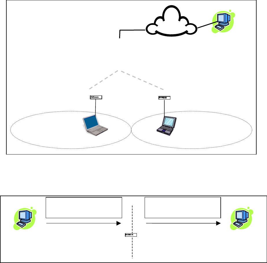
4.8.3.3.1.1 NAT on ViPR
When NAT is enabled on an ViPR unit, the network covered by the Ethernet interface is considered
private.
Figure 33 - NAT Enabled on ViPR
An IP packet sent from the private network towards the public network will have its source IP address
replaced by the RF IP address of the ViPR unit.
Figure 34 - Private to Public
External Host 1
200.1.1.1/24
RF Network
Public Network
(External Network + RF Network)
Remote Private Network 1
Packet (1)
Source Address 172.30.1.2
Destination Address 200.1.1.1
Packet (1)
Source Address 172.31.1.2
Destination Address 200.1.1.1
172.30.1.1/24 172.31.1.2/24
ViPR (NAT Enabled)
Management Host 1
172.30.1.2/24
External Host 1
200.1.1.1/24
Private network (172.30.1.0/24) Public network (RF+External)
Master ViPR unit
Ethernet 1
172.32.1.1/24
Remote Host 1
172.30.1.2/24
Remote ViPR unit
(
NAT enabled
)
Remote ViPR unit (NAT enabled)
RF 172.32.1.1/24 RF 172.31.1.3/24
172.30.1.1/24 172.30.1.1/24
Remote Host 2
172.30.1.2/24
RF 172.31.1.1/24
Remote Private Network 2
External
Network
120 40520-100a ViPR User Manual
46

4.8.3.4 IP addressing modes
Figure 35 - Advanced IP Configuration – IP adressing modes
Item Description
Disabled, Enabled (Default) – Controls forwarding of
Directed Broadcast packets
Directed Broadcast
Broadcast
Limited Enable Disabled (Default), Enabled – Controls forwarding of
Limited broadcast packets
Multicast
Disabled (Default), Enabled – Controls forwarding of
Multicast packets (based on the “Multicast Address
List”)
Multicast can be used when “one-to-many”
communication is required.
Outbound unit address Multicast address associated to remote unit
Multicast Address List
Add / Delete Address
To add an address to the Multicast List:
Select the “Add” radio button and type in the dialog
box the new address to be added to the read-only
“Address List”. Note that only the valid multicast
addresses will be accepted and displayed.
To delete an address from the Multicast List:
Select the “Delete” radio button and type in the dialog
box the address to be deleted from the “Address List”.
Multicast
Address List
Read-only listing. Window expands downward as
needed to show all addresses in the list.
When an IP packet is received on the Ethernet side of
the unit and the destination IP address matches one of
the multicast IP addresses in this list, it is forwarded
over the RF interface.
Remote units will send it over their Ethernet interface.
120 40520-100a ViPR User Manual
47
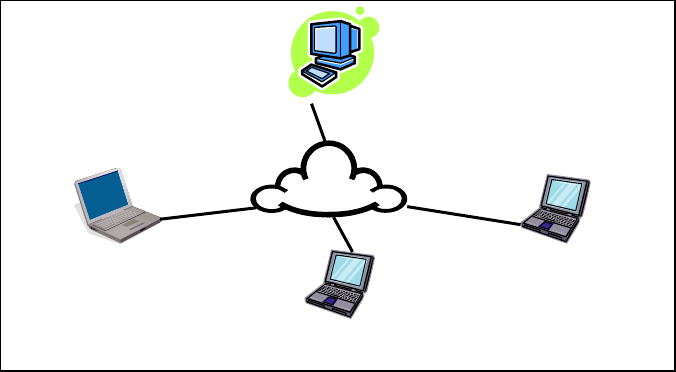
4.8.3.4.1 IP Broadcast/Multicast Overview
When an IP packet needs to reach more then one unit, the destination address can be set to either a
broadcast address or a multicast address.
BROADCAST - There are two types of IP broadcast address:
• Directed broadcast
A directed broadcast address is an IP address where the host portion is all ones (for instance
172.30.1.255 is the directed broadcast address for the network 172.30.1.0/24, 172.30.1.207 is the
directed broadcast address for the network 172.30.1.192/28).
Note:
Routing equipment (to prevent broadcast storms) do not by default forward limited
broadcast packets (255.255.255.255). On the other hand, directed broadcast packets are
by default forwarded because these packets are routable like any other unicast packets.
• Limited broadcast
The limited broadcast address is 255.255.255.255.
MULTICAST - IP multicast addresses are in the range 224.0.0.0 to 239.255.255.255. These addresses
are used to represent logical groups of units that may or may not reside on the same networks.
Multicast is used when “one-to-many” communication is required. For instance, a radio station might
offer a music channel on the Internet in real time. To receive the music a user (host) must know the
multicast group (multicast address) used by the radio station and add itself as a member of this group. In
the IP realm, a host uses the IGMP protocol to do this. The routers inside the Internet are using IGMP and
other multicast routing protocol to build the proper path from the sender to the receivers (a tree like path
is formed from the sender to the receivers).
Sender (owner of multicast group 226.1.2.3)
Receiver 1
(Add membership 226.1.2.3)
Receiver 2
(Add membership 226.1.2.3)
Receiver 3
(Add membership 226.1.2.3)
Internet
Figure 36 - Registration to multicast group (First step)
120 40520-100a ViPR User Manual
48
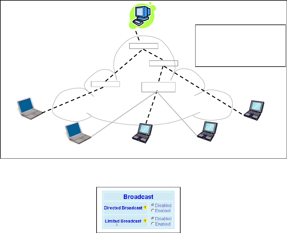
Sender (owner of multicast group 226.1.2.3)
Receiver 1
(member of 226.1.2.3)
Receiver 2
(member of 226.1.2.3)
Receiver 3
(member of 226.1.2.3)
Internet
IP Router
IP Router
IP Router
IP Router
Paths from Sender to Members
(Receivers 1, 2, and 3) flow in the Internet
from IP Router to IP Router to reach
Destinations 226.1.2.3.
Paths are not forwarded over interfaces
that do not lead to a multicast group
b
5
1
22
3
3
4
Receiver
(not a member of 226.1.2.3)
Receiver
(not a member of 226.1.2.3)
Figure 37 - Reception of multicast packets (Second step)
4.8.3.4.1.1 Broadcast
Figure 38 - Broadcast Window Detail
DIRECTED BROADCAST
Each interface of a unit has its own IP address and netmask. From the IP address and netmask, it is easy
to calculate the broadcast address associated to the interface. For instance, if the Ethernet interface
address of an ViPR unit is 172.30.1.1/24 and the RF interface address is 10.0.1.2/24, then the broadcast
address of the Ethernet interface is 172.30.1.255 and the broadcast address of the RF interface is
10.0.1.255.
The “Directed Broadcast” radio buttons let the user select whether the unit must forward or not directed
broadcast packets. Upon reception of a directed broadcast packet, the unit takes the following actions:
If the directed broadcast address match with one of the unit’s interface broadcast address:
• Keep a copy for itself (pass to internal applications, if any).
• If directed broadcast packets can be forwarded:
Forwards the packet according to the routing table.
• If directed broadcast packets cannot be forwarded:
Silently discards the packet.
120 40520-100a ViPR User Manual
49
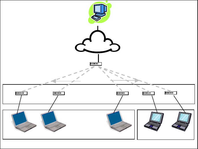
Note:
Occasionally, the unit cannot determine that the packet is actually a directed broadcast. In such a
case, the packet is normally routed.
LIMITED BROADCAST
The “Limited Broadcast” radio buttons let the user select whether the unit must forward or not limited
broadcast packets. Upon reception of a limited broadcast packet, the unit takes the following actions:
• Keep a copy for itself (pass to internal applications, if any).
• If limited broadcast packets can be forwarded:
Sends a copy of the packet out of all the interfaces at the exception of the interface where the packet
was received.
• If limited broadcast packets cannot be forwarded:
Silently discards the packet.
4.8.3.4.1.2 Multicast
In an ViPR environment, an outside host (Sender) might be interested in sending multicast packets to any
one of the following groups:
• “All Remote ViPR” group.
• Various “Remote Host” group.
The main ViPR unit is directly connected to the outside network. ALL multicast groups MUST be
identified in the main ViPR unit because it uses IGMP to register the memberships to the multicast groups
on behalf of the other units and Hosts (Remote ViPR units, Remote Hosts).
Sender
Network
“All Remote ViPR” group
RF Airlinks
Remote Host Remote Host Remote Host Remote Host Remote Host
“Remote Host” group 1 “Remote Host” group 2
Remote 1 Remote 2 Remote 3 Remote 4 Remote 5
Master ViPR unit
Figure 39 - Typical ViPR Multicast Groups
120 40520-100a ViPR User Manual
50
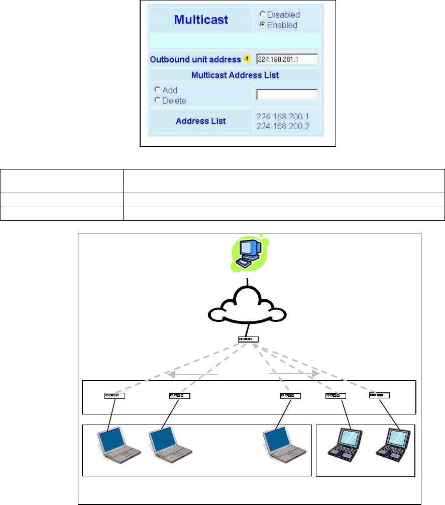
The following setup example would allow the “Sender” unit to communicate with different multicast
groups. The settings shown in Figure 40 below, and also represented in Figure 41, would enable the
Sender unit to reach all entities of the various groups. Setup is done on the Base side.
Figure 40 - Multicast Window Details (On the Main ViPR unit)
Multicast (Enabled/Disabled) Enables or disables the registration of the multicast groups by the main ViPR
unit.
Outbound unit address Indicates the “All Remote ViPR unit” multicast group
Multicast Address List Indicates the various “Remote Host” groups
Sender
Network
“All Remote ViPR”
group
(224.168.201.1)
Master ViPR unit
RF Airlinks
Remote Host Remote Host Remote Host Remote Host Remote Host
“Remote Host” group 1
(224.168.200.1) “Remote Host” group 2
(224.168.200.2)
Remote 1 Remote 2 Remote 3 Remote 4 Remote 5
Figure 41 - Registration to multicast group
120 40520-100a ViPR User Manual
51

4.8.3.5 IP Optimization & Tuning
Figure 42 - Advanced IP Configuration – IP Optimization & Tuning (Router Mode)
Item Description
RF ACK Disabled, Enabled (Default)
OIP Retries Number of OIP retries. Default = 1
Note: No optimizations are available in Bridge Mode. Figure 42 shows Router mode screen.
120 40520-100a ViPR User Manual
52

4.8.3.6 Time Source
Figure 43 - Advanced IP Configuration – Time Source
Item Description
Client Disabled (Default), Enabled
Server address IP of the SNTP Server in dot decimal format
Period Period at which the SNTP Server is polled
SNTP UTC Time Last update received from the SNTP Server (in seconds) – Read only
TimeZone Select from drop-down list
SNTP
Daylight Savings Disabled (Default), Enabled
120 40520-100a ViPR User Manual
53

4.8.3.7 Ethernet (PHY)
Figure 44 - Advanced IP Configuration – Ethernet (PHY)
Item Description
PHY Bitrate
Auto Negotiate
Force to 100 Mbps
Force to 10 Mbps (Default)
PHY Duplex
Auto Negotiate
Force to Full Duplex
Force to Half Duplex (Default)
4.8.3.8 RF Link
Figure 45 - Advanced IP Configuration – RF Link
Item Description
TDD Mode
Disabled, Enabled (Default) –
Normally used in a point- to- point network carrying Ethernet traffic. Maximizes RF link
efficiency for carrying two-way traffic
120 40520-100a ViPR User Manual
54

4.8.4 Security
4.8.4.1 Pass Control
Figure 46 - Security – Pass Control
Item Description
User ID
Enter a string of any letters or numbers of at least 1 and not exceeding 15 characters
The User Name entry is currently not an access-limiting factor. It only serves to identify the
person gaining access. User Name may be required by future versions.
For an initial installation, enter the default Password ADMINISTRATOR (all upper case
letters). For subsequent access, use the Password that you will have configured.
Old Password
New Password
Enter a string of any letters or numbers of at least 8 and not exceeding 15 characters
CAUTION: Do not lose the new password or you will not be able to gain access to the unit;
you will need to contact Dataradio for support as detailed in section 1.3 earlier.
New Password
(confirm) Re-enter the new password string
Encryption Disabled, Enabled (Default)
Encryption Pass
Phrase
String of characters used to create a 128-bit AES encryption key. The Pass Phrase can be
up to 160 characters long. Using a length of at least 128 characters should provide an
adequate security level for most users.
A good pass phrase mixes alphabetic and numeric characters, and avoids simple prose
and simple names.
Encryption Key All units in a network must have the same key.
READ ONLY - Displayed in pairs separated with spaces
120 40520-100a ViPR User Manual
55

4.8.4.2 Access List
Figure 47 - Security – Access List
Item Description
Access List
Control Access List Control
Access List is used to keep unauthorized unit(s) away from Dataradio RF
network. Maximum number of Access List entries = 100.
The Access List Control takes the following values:
Disabled (Default)
White List – Authorized units only. Requests from any unit(s) outside this
list will be rejected.
Black List – Unauthorized units. Requests from any unit(s) that is part of
this list will be rejected
Add Entry Adds entry in the Access Control List
Delete Entry Deletes entry in the Access Control List
Import Access list
from file
Imports Access List from file – Populates Access Control table from the
file “accesslist.acl“. It is basically a text file that contains a list of
RF MAC addresses.
E.g.:
0x1234
abcd
2345
where, 0x1234, abcd, and 2345 represent RF MAC addresses in HEX
To use this feature:
-Create a text file “accesslist.acl” with a list of RF MAC addresses
-Upload the file from a host PC via an FTP program
-Click on “Import Access list from file” button
-Click on “Display Access List” button to view the imported access list
Clear Access List Clears entire Access Control table
Access List
Management
Display Access List Clicking this button opens the access list in the message window
120 40520-100a ViPR User Manual
56

4.8.5 Statistics
4.8.5.1 TCP/IP
Figure 48 - Statistics – TCP/IP
Item Description
TCP – RX Pkts Total number of packets received by the TCP layer
TCP – TX Pkts Total number of packets sent by the TCP layer
UDP – RX Pkts Total number of packets received by the UDP layer
UDP – TX Pkts Total number of packets sent by the UDP layer
ICMP – RX Pkts Total number of packets received by the ICMP layer
ICMP – TX Pkts Total number of packets sent by the ICMP layer
IP – RX Pkts Total number of packets received by the IP Interface
IP – RX Pkts Forwarded Total number of packets forwarded by the IP Interface
IP – TX Pkts Total number of packets sent by the IP Interface
120 40520-100a ViPR User Manual
57

4.8.5.2 AirLink
The Airlink RF layer (good/bad CRC) indicates how well it receives individual packets. Missing and bad
CRC counts should be minimized with respect to the good CRC count. To optimize the Airlink, refer to
section 5 below.
Figure 49 - Statistics – Airlink – Channel Utilization
Item Description
Pkts Delivered Total packets delivered over-the-air
Pkts Received Total packets received by over-the-air
Pkts with Good CRC Total packets received over-the-air with correct checksum
Pkts with Bad CRC Total packets received over-the-air with incorrect checksum
Airlink
statistics
Pkts with missing fragments Total packets received over-the-air with missing fragments
4.8.5.3 Interfaces
The LAN (Ethernet) Interface layer shows reception and transmission traffic counts.
The RF(OIP) interface layer indicates the result of the RF link performance. RF errors result in RX Error
counts. Transmission errors show up as retries and timeouts and appear as TX Error counts.
Figure 50 - Statistics – Interfaces
Item Description
RX Pkts Total packets received by Ethernet interface
LAN(LAN) TX Pkts Total packets sent by Ethernet interface
RX Pkts Total packets received by RF (OIP) interface
RX Error Total packets received by RF (OIP) interface with errors
TX Pkts Total packets transmitted by RF (OIP) interface
RF(OIP)
TX Error Total packets transmitted by RF (OIP) interface with errors
120 40520-100a ViPR User Manual
58

4.8.6 Maintenance
4.8.6.1 Ping Test
Figure 51 - Maintenance – Ping Test
Item Description
Enter IP address Enter IP address in dot decimal format
This button executes the ping command. Ready field displays the
outcome of the ping command.
Execute
120 40520-100a ViPR User Manual
59

4.8.6.2 Unit Configuration Control
Important note: Record all original ViPR radiomodem factory settings for possible future use.
Figure 52 - Maintenance - Unit Configuration Control (Initial screen)
Item Description
Active Configuration Description
Active Configuration Description Field – available by selecting
“Checkpoint User Configuration” radio button in the “User
Configuration Settings “portion of this window below.
Checkpoint User Configuration (Save User Configuration) – saves a set
of the current user configuration settings in the ViPR unit.
Click on the “Checkpoint User Configuration” radio button to activate
the “Active Configuration Description” field. Enter a descriptive title of
up to 40 characters to help identify the configuration settings to be
saved. Click on “Proceed” to save the settings to the unit. The new
configuration set overwrites the factory (or previously user saved)
configuration settings.
User Configuration Settings
Restore User Configuration Checkpoint (Load User Configuration) – the
radio button is available if “User Configuration Settings” have been
previously saved. To restore to user configuration, click the “Restore
User Configuration” radio button. Check the title of the settings about
to be restored in the “Active Configuration Description” field and click
on “Proceed” to restore the settings to the unit.
Firmware Upgrade Settings
Merge settings bundled in upgrade package with current configuration-
merges upgraded settings with the current configuration.
Note: the "firmware update" process will end up replacing an existing
configuration file with the one that came bundled with the firmware
upgrade package.
Factory Settings
Restore Factory Settings: restores all settings do default factory
configuration.
Upon performing the firmware upgrade, should you decide to restore to
factory settings instead of to “merge with bundled settings”, simply
select the “Restore Factory Settings’ radio button right after performing
the firmware upgrade and click on “Proceed”.
Important note:
Activating “ Restore Factory Settings” will reset the IP address of the
unit. Have your record of all the original ViPR factory settings handy
before proceeding with restoring to factory settings.
120 40520-100a ViPR User Manual
60

4.8.6.3 Package Control
Package Control is used for verifying the integrity of the field upgrade of the ViPR radiomodem
firmware.
Click on Maintenance/Package Control and wait a few seconds for the results to display.
Snapshot in Figure 53 shows a “PASS” result indication. If an upgrade problem arises and persists, click
the “Package Control” once more and have the resulting indications handy if contacting Dataradio System
engineering.
Figure 53 – Package Control
120 40520-100a ViPR User Manual
61

4.8.7 Radio - RF Tests
To guard against an inadvertent or accidental mishap, Dataradio strongly recommends saving the
parameters to the unit BEFORE running this test. Use the “Save Config” button at the bottom of the
navigation menu. This test is especially useful for testing the power output with a wattmeter.
Figure 54 - RF Tests
Item Description
Start Test
Test frequency is xxx.xxx MHz, carrier only (no modulation)
RF Power will be as configured in:
“Setup (Basic)” Î “RF Setup” (30 to 40 dBm)
Stop Test ViPR unit resets after 20 seconds if the Stop Test button is not pressed.
4.8.8 Help
Figure 55 - Help Icon
Item Description
Click the Help Icon in the navigation pane to open a help text relating to
the window being displayed.
Help Icon
120 40520-100a ViPR User Manual
62
5. Optimization & Troubleshooting
After original setup is complete, you may wish to maximize performance by first optimizing the Airlink
(or RF link) and then optimizing the ViPR radio modem to function in the resulting environment.
120 40520-100a ViPR User Manual
63
120 40520-100a ViPR User Manual
64
5.1 Maximizing TCP/IP
If after optimizing the airlink there still appears to be an unexplained speed loss, you can look at
maximizing TCP/IP.
TCP/IP throughput can be tricky to measure as performance is related not only to the RF link, but how
well flow control is implemented in the TCP/IP stack and how each application is designed. The ViPR
has been highly optimized with this in mind. When the TX/RX LED flashes amber, this not only indicates
that data is moving but also indicates (by the LED OFF periods) when data is not moving across the RF
network at full rated speed. If you get flashing RED indications on the TX/RX LED, RF reception
problems are present and causing some loss of throughput. OFF periods indicate that the application has
not presented data to the ViPR radio modem.
Using different client/server combinations or applications may show improvements. For instance, one
FTP server may work 30% faster than another, simply because the buffer management is quicker to
respond or has bigger message buffers – yet run at nearly the same speed over a pure Ethernet (no RF)
link.
Network Address Translation (NAT), payload data compression and encryption have little effect other
than adding a small latency to the flow of traffic.
The TDD mode should be left enabled unless highly specialized protocols are being run. Sometimes,
these protocols and TDD interfere which each other and may run somewhat faster with TDD disabled.
5.2 Maximizing via Setup Pages
Further performance optimization can be done via the User Interface Setup pages. The fundamental
adjustments described in the following paragraphs can be changed singularly or in conjunction with each
other
Note: Data Compression (section 4.8.3.5 above) should only be OFF while testing, thereby eliminating
performance differences due only to different compression rates.
5.2.1 Use Router Mode
Selecting Router mode (see section 4.8.2.1) is highly recommended when running over a weak RF link.
This mode ensures that several levels of retry mechanisms are at work, each optimized to minimize TCP
flow control delays or even preventing a dropped TCP/IP link. It requires some IP route planning to and
from the ViPR units but is well worth the increase in link stability over the simpler bridge mode
5.2.2 Reduce RF network bit rate
Normally the system is able to utilize the normal bit rate of xxK (see section 4.8.2.3). If you have a very
low signal level (-90 dBm or less) or the RF signal levels are close to an elevated noise floor level, you
can try running at xxK instead of xxK (changeable on the fly without a reset). It could result in better
overall performance.
120 40520-100a ViPR User Manual
65
5.2.3 Increase OIP Retries Limit
Only available in Router mode, OIP Retries Limit is normally set to two (2). Gradually increasing it up to
five (5) in extreme cases, may provide a slow but reliable link when none was possible with weak signals.
Use in conjunction with a xxK network bit rate.
5.3 Troubleshooting Tools
5.3.1 Network Connectivity
• PING
The ping command determines whether a specific IP address is accessible. It works by
sending a packet to the specified address and waiting for a reply. It is useful for
troubleshooting “end-to-end” reachability, network connectivity, and network latency.
Available for MS-Windows 9x, ME, NT, 2000, and XP as well as Unix & Free BSD.
EXAMPLE:
ping 192.168.204.1 displays the response with turn around time in milliseconds.
• TRACERT (WINDOWS)
The tracert command is used to visually see a network packet being sent and received and
the number of hops required for that packet to get to its destination.
Available for MS-DOS 6.2, MS-Windows 9x, ME, NT, 2000, and XP.
Note:
Users with MS-Windows 2000 or XP who need additional information on network
latency and network loss may also use the pathping command.
EXAMPLE
tracert www.yahoo.com at the command prompt displays the intermediate routers
between local host to the www.yahoo.com site.
120 40520-100a ViPR User Manual
66

5.3.2 Configuration Information
• WINIPCFG (WIN95/98), IPCONFIG (WIN2K) or IFCONFIG (UNIX)
Ipconfig is a DOS utility, which can be used from MS-DOS or a MS-DOS shell to display
the network settings currently assigned and given by a network. This command can be
utilized to verify a network connection as well as to verify network settings.
Available for MS-DOS, MS-Windows 9x, ME, NT, 2000, and XP.
EXAMPLE
ipconfig /all at the command prompt displays the Ethernet MAC address, IP address,
IP netmask, default IP gateway, DNS server… information.
• ARP
View and update the system ARP table
The Address Resolution Protocol (ARP) is used with the IP protocol for mapping a 32-bit
Internet Protocol address to a MAC address that is recognized in the local network specified
in RFC 826. Once recognized the server or networking device returns a response containing
the required address.
Available for MS-Windows 9x, ME, NT, 2000, and XP.
EXAMPLE
arp -a displays all entries in the ARP cache. Useful in manipulating ARP caches.
• ROUTE
View and update the system routing table
The function and syntax of the Windows ROUTE command is similar to the UNIX or Linux
route command. Use the command to manually configure the routes in the routing table.
Available for MS-Windows 9x, ME, NT, 2000, and XP.
EXAMPLE
route ? displays help
route print displays the routing table
5.3.3 Statistics Information
• NETSTAT (WINS & UNIX)
The netstat command symbolically displays the contents of various network-related data
structures, i.e. IP, TCP UDP …
Available for MS-Windows 9x, ME, NT, 2000, and XP.
EXAMPLE
netstat ? displays help
netstat -a display TCP and UDP connections and listening ports information
For further information on TCP/IP troubleshooting, please visit:
http://www.windowsitlibrary.com/Content/466/14/1.html
120 40520-100a ViPR User Manual
67

5.4 Firmware Upgrading
The ViPR radiomodem firmware is field-upgradable using the unit’s Ethernet port. The process involves
connecting to the IP address of the mobile from a host PC and transferring the firmware files via an FTP
program.
5.4.1 Procedure
1. Using a file decompression program, such as WinZIP™ or WinXP’s right-click & select the “Expand
to…” option, expand the contents of the firmware upgrade package to a directory of your choice on
the host PC.
Warning:
Be aware that base and mobile’s firmware archives are often distributed at the same time. Files
intended for the ViPR radiomodem are labeled in the form ViPR_Vx.x_Rx.xx.zip. Be
careful not to transfer firmware into the wrong unit!
2. Using an FTP program of your choice, establish a connection to the mobile IP address. Please refer to
paragraph 4.8.4.1 for “Username” and “Password” usage.
3. Transfer all the files in the upgrade package. Occasionally, long pauses, on the order of 30 to 45
seconds, are possible when storing the file in the unit’s flash file system.
4. Once the file transfer is complete, cycle the mobile power and allow the unit to boot. The unit should
return to the state that it was in when the update was started.
Note:
After resetting, the PWR LED remaining lit steady amber or red indicates the FTP transfer was
not successful or that the firmware is corrupt. Please contact Dataradio system engineering for
assistance.
120 40520-100a ViPR User Manual
68
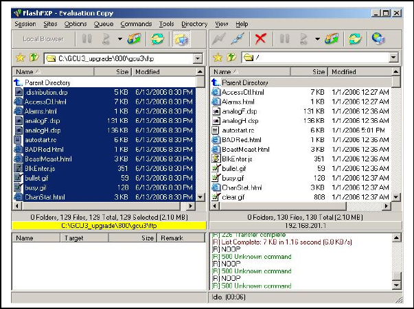
5. Verify the integrity of the newly transferred files.
a) Connect to the mobile’s IP address using an Internet browser such as IE (5.0 or later) or Mozilla.
b) Enter the user name and password (in the usual manner) and allow the Welcome page to load.
c) In the left pane, click on Unit Status. The Unit Identification and Status pane should display the
newly upgraded firmware in its Banner (should correspond to the upgrade package version) and the
H/W Status should also show Ok.
d) In the left pane, click on Maintenance, then on Package Control. Wait a few moments for the
results to display. Figure 53 shows a “Pass” result indication.
Figure 56 - Sample FTP program
5.4.1.1 File Integrity Failure
If the message in the result screen points out that file(s) failed the integrity check, retry the FTP transfer
for the failed files(s) again.
If the problem persists, please have the Package Control result screen indications handy and contact
Dataradio system engineering for assistance
120 40520-100a ViPR User Manual
69

6. Specifications
These specifications are subject to change without notice.
GENERAL
UHF
Frequency Range (MHz) 406.1 - 470 MHz
450 - 512 MHz
Frequency Stability 0.5 ppm
Modes of Operation Simplex, Half-Duplex, Full Duplex
Channel Bandwidth 6.25 kHz
12.5 kHz
25 kHz
Frequency Increment 1.25 kHz
Power Source 10-30 VDC, Negative GND
RF Impedance 50 Ω
Operating Temperature -30° to + 60° C
Storage Temperature -40° to + 85° C, 95% non-condensing RH
Operating Humidity 5% to 95% non-condensing RH
DC Input 10V DC Input 20V DC Input 30V
Typical Rx Current Drain at 25°C
480 mA 250 mA 180 mA
Power Out DC Input 10V DC Input 20V DC Input 30V
40 dBm (10W) 4.6 A 2.04 A 1.37 A
Typical Tx Current Drain at 25°C
30 dBm (1W) 1.23 A 630 mA 440 mA
Cold start 10 seconds (typical)
Nominal Dimensions 5.50" W x 2.125” H x 4.25" D (13.97 x 5.40 x 10.8 cm)
Shipping Weight 2.4 lbs. (1.1 Kg)
Mounting Options 19’’ Rack mount configuration, DIN-rail option, Mounting plate/pattern
TRANSMITTER
406.1-470 MHz, 450-512 MHz
Tx Frequencies
1-12W Adjustable
Carrier Output Power
Duty Cycle 100%
Radiated Spurious Emissions Per FCC/Regulatory
Conducted Spurious Emissions -65 dBc
Transmitter Stability into VSWR: > 10:1 (Power Foldback Allowed)
RX to TX Time < 2ms
Channel Switching Time < 15 ms (Band-End to Band-End)
RECEIVER
406.1-470 MHz, 450-512 MHz
RX Frequencies
25 kHz Channel 12.5 KHz Channel 6.25 kHz Channel
Data Sensitivity @ 10-6
Bit Error Rate (BER)
-112 dBm @ 16kb/s (typical)
-105 dBm @ 32kb/s (typical)
-112 dBm @ 8kb/s (typical)
-105 dBm @ 16kb/s (typical)
-112 dBm @ 4kb/s (typical)
-96 dBm @ 8kb/s (typical)
Adjacent Channel Rejection > 70 dB > 60 dB > 55 dB
Spurious Response Rejection > 70 dB
Intermodulation Rejection > 70 dB
120 40520-100a ViPR User Manual
70

TX to RX Time < 1ms
Channel Switching Time < 15ms (Band-End to Band-End)
Carrier to Data Time None (140 µs)
Modem / Logic
25 kHz Channel 12.5 KHz Channel 6.25 kHz Channel
Data Rate (User Selectable) 16 kb/s
32 kb/s
8 kb/s
16 kb/s
4 kb/s
8 kb/s
Modulation Type 2FSK, 4FSK
Addressing IP
SETUP and COM Port
Interface EIA RS-232F DE9F
Data Rate 300 – 115,200 b/s (Defaults: Setup = 115.2Kbps, COM = 9.6 Kbps)
Display
5 Bi-color status LEDs Power, Status, LAN Link/Activity, Collision, Rx/Tx
Connectors
Antenna Connector Half Duplex/Simplex: TNC female (Tx/Rx)
Full Duplex: TNC female (Tx) & SMA female (Rx)
Serial Setup Port DE-9F
Serial Terminal Server DE-9F
Ethernet RJ-45 10/100 BaseT auto-MDIX
Power Header Power Plug Power -I/O
DRL p/n 415-7108-113
(Weidmüller p/n 1615550000)
4 Pin, 3.5mm, Power Header
DRL p/n 415-7140-113
(Weidmüller p/n 1639260000)
4 Pin, 3.5mm, Power Plug
Diagnostics
IP or MAC Address, Thinning value, Flag/Voltage source, Voltage, Temperature, Packet
Error Rate, Carrier Level, Average Background Level, Forward power, Reverse power
Message elements
FCC / IC / UL Certifications
FCC IC (DOC) UL
406.1 - 512 MHz NP4-5048300 773B-5048300 Pending
120 40520-100a ViPR User Manual
71

Appendix 1 - Data Telemetry Warranty
Dataradio COR Ltd. ("DRL") warrants to the original purchaser for use ("Buyer") that data telemetry products manufactured by DRL
("Products") are free from defects in material and workmanship and will conform to DRL's published technical specifications for a
period of, except as noted below, two (2) years from the date of shipment to Buyer. DRL makes no warranty with respect to any
equipment not manufactured by DRL, and any such equipment shall carry the original equipment manufacturer's warranty only. DRL
further makes no warranty as to and specifically disclaims liability for, availability, range, coverage, grade of service or operation of the
repeater system provided by the carrier or repeater operator. Any return shipping charges for third party equipment to their respective
repair facilities are chargeable and will be passed on to the Buyer.
If any Product fails to meet the warranty set forth above during the applicable warranty period and is returned to a location designated
by DRL. DRL, at its option, shall either repair or replace such defective Product, directly or through an authorized service agent, within
thirty (30) days of receipt of same. No Products may be returned without prior authorization from DRL. Any repaired or replaced
Products shall be warranted for the remainder of the original warranty period. Buyer shall pay all shipping charges, handling charges,
fees and duties for returning defective Products to DRL or DRL's authorized service agent. DRL will pay the return shipping charges if
the Product is repaired or replaced under warranty, exclusive of fees and duties. Repair or replacement of defective Products as set forth
in this paragraph fulfills any and all warranty obligations on the part of DRL.
This warranty is void and DRL shall not be obligated to replace or repair any Products if (i) the Product has been used in other than its
normal and customary manner; (ii) the Product has been subject to misuse, accident, neglect or damage or has been used other than with
DRL approved accessories and equipment; (iii) unauthorized alteration or repairs have been made or unapproved parts have been used
in or with the Product; or (iv) Buyer failed to notify DRL or DRL's authorized service agent of the defect during the applicable
warranty period. DRL is the final arbiter of such claims.
THE AFORESAID WARRANTIES ARE IN LIEU OF ALL OTHER WARRANTIES, EXPRESSED AND IMPLIED, INCLUDING
BUT NOT LIMITED TO, ANY IMPLIED WARRANTY OF MERCHANTABILITY OR FITNESS FOR A PARTICULAR
PURPOSE. DRL AND BUYER AGREE THAT BUYER'S EXCLUSIVE REMEDY FOR ANY BREACH OF ANY OF SAID
WARRANTIES IT AS SET FORTH ABOVE. BUYER AGREES THAT IN NO EVENT SHALL DRL BE LIABLE FOR
INCIDENTAL, CONSEQUENTIAL, SPECIAL, INDIRECT OR EXEMPLARY DAMAGES WHETHER ON THE BASIS OF
NEGLIGENCE, STRICT LIABILITY OR OTHERWISE. The purpose of the exclusive remedies set forth above shall be to provide
Buyer with repair or replacement of non-complying Products in the manner provided above. These exclusive remedies shall not be
deemed to have failed of their essential purpose so long as DRL is willing and able to repair or replace non-complying Products in the
manner set forth above.
This warranty applies to all Products sold worldwide.
Some states do not allow limitations on implied warranties so the above limitations may not be applicable. You may also have
other rights which vary from state to state.
EXCEPTIONS
ONE YEAR: Labor to replace defective parts in repeaters or base stations
THIRTY DAY: Tuning and adjustment of telemetry radios
NO WARRANTY: Fuses, lamps and other expendable parts
Effective 01/2004
Dataradio COR Ltd. 299 Johnson Avenue, Suite 110, Waseca, MN 56093-0833: Tel: (507) 833-8819 or (800) 992-7774; Fax: (507) 833-6748 Visit us on the web at www.dataradio.com
120 40520-100a ViPR User Manual
72

The entire contents of this manual are Copyright 2006 by DATARADIO Inc.®
Dataradio, ViPR and PARALLEL DECODE are registered trademarks. TRUSTED WIRELESS DATA is a trademark of Dataradio
Inc.
120 40520-100a ViPR User Manual
73