CalAmp Wireless Networks GPDA GeminiPD User Manual Appendix A preliminary version 1 42
CALAMP WIRELESS NETWORKS INC. GeminiPD Appendix A preliminary version 1 42
UserManual.wiki
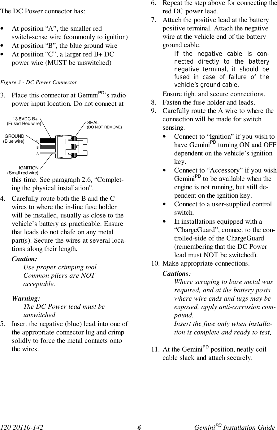
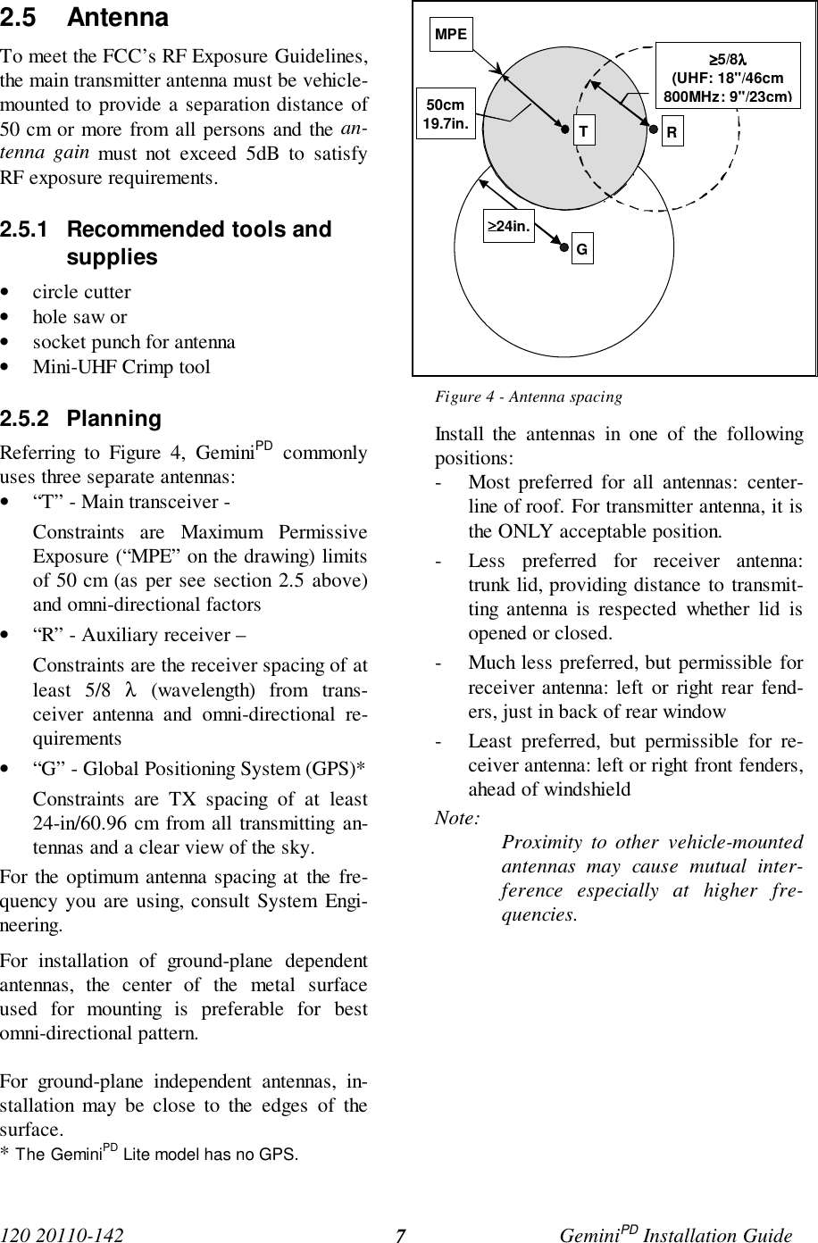
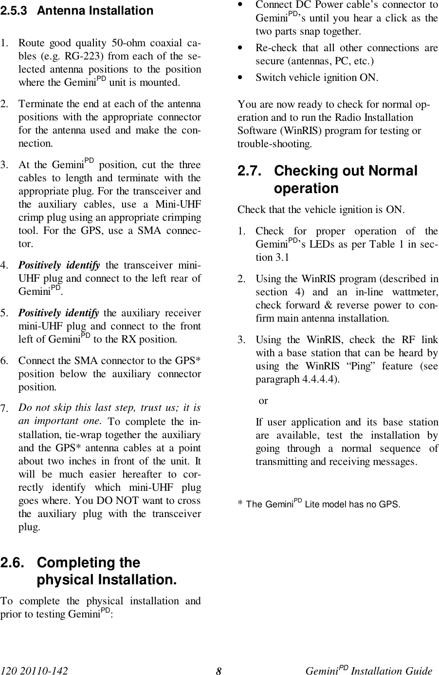
>
CalAmp Wireless Networks
>
GPDA User Manual
>
Appendix A preliminary version 1 42
Contents
1.
service manual preliminary version
2.
preliminary release of the user manual
3.
Appendix A preliminary version 1 42
4.
preliminary instalation manual
5.
preliminary user manual
6.
preliminary version of user manual
7.
updated user manual
Appendix A preliminary version 1 42
Navigation menu
Upload a User Manual
Namespaces
Wiki Guide
HTML
PDF
Info
Views
User Manual
Discussion / Help
Navigation

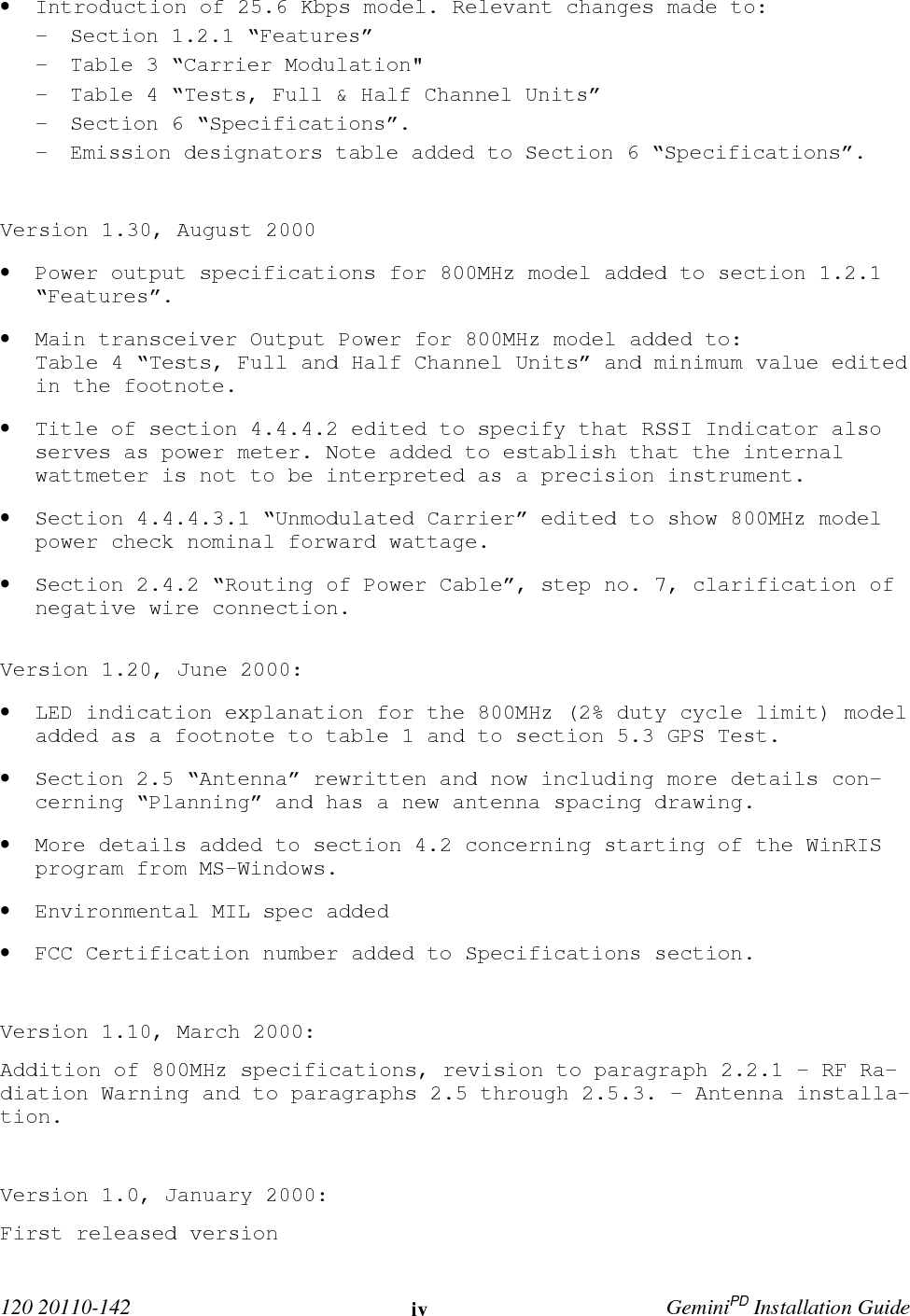

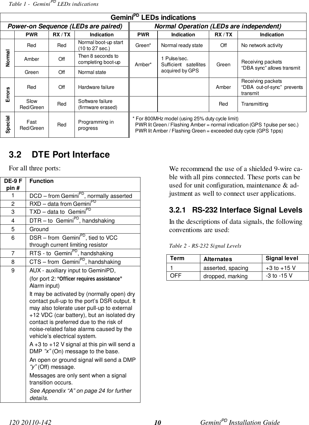
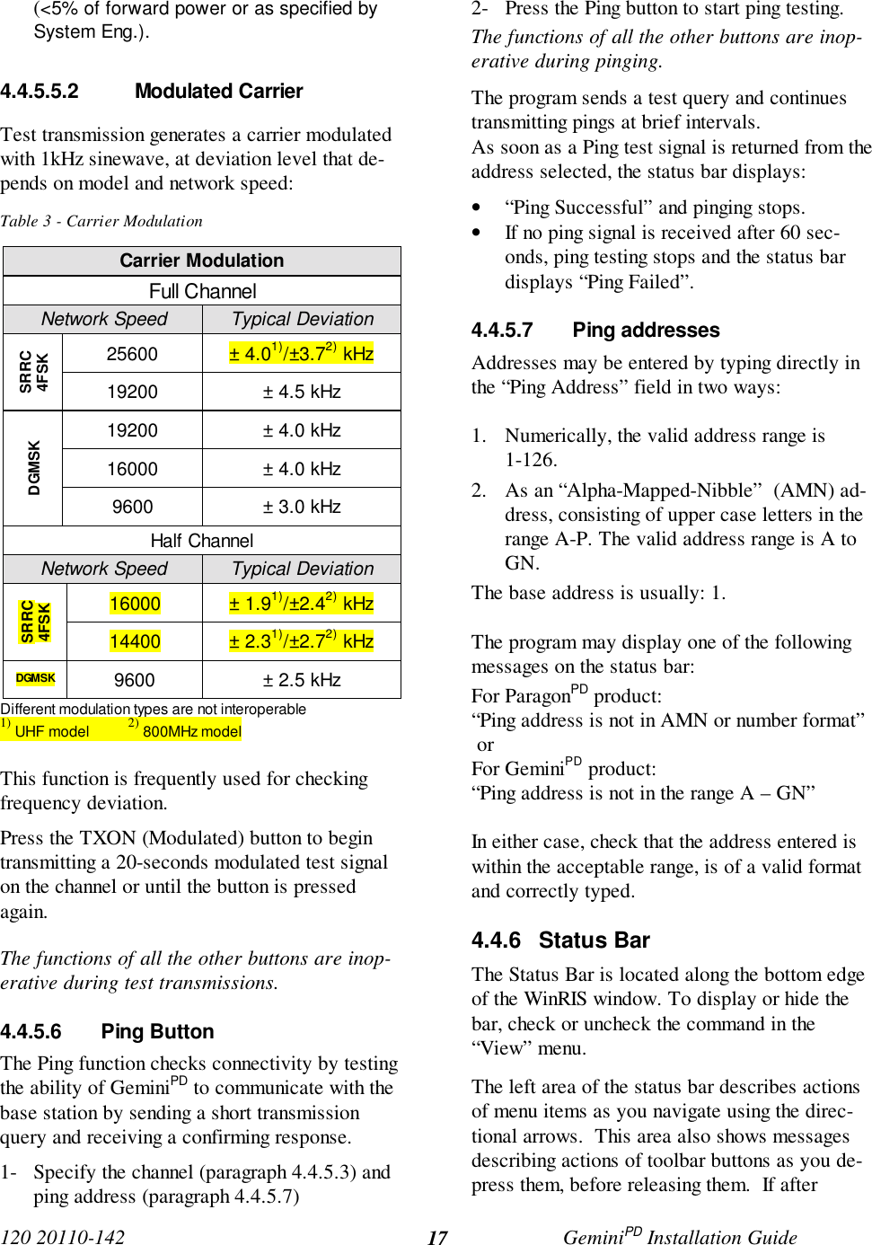
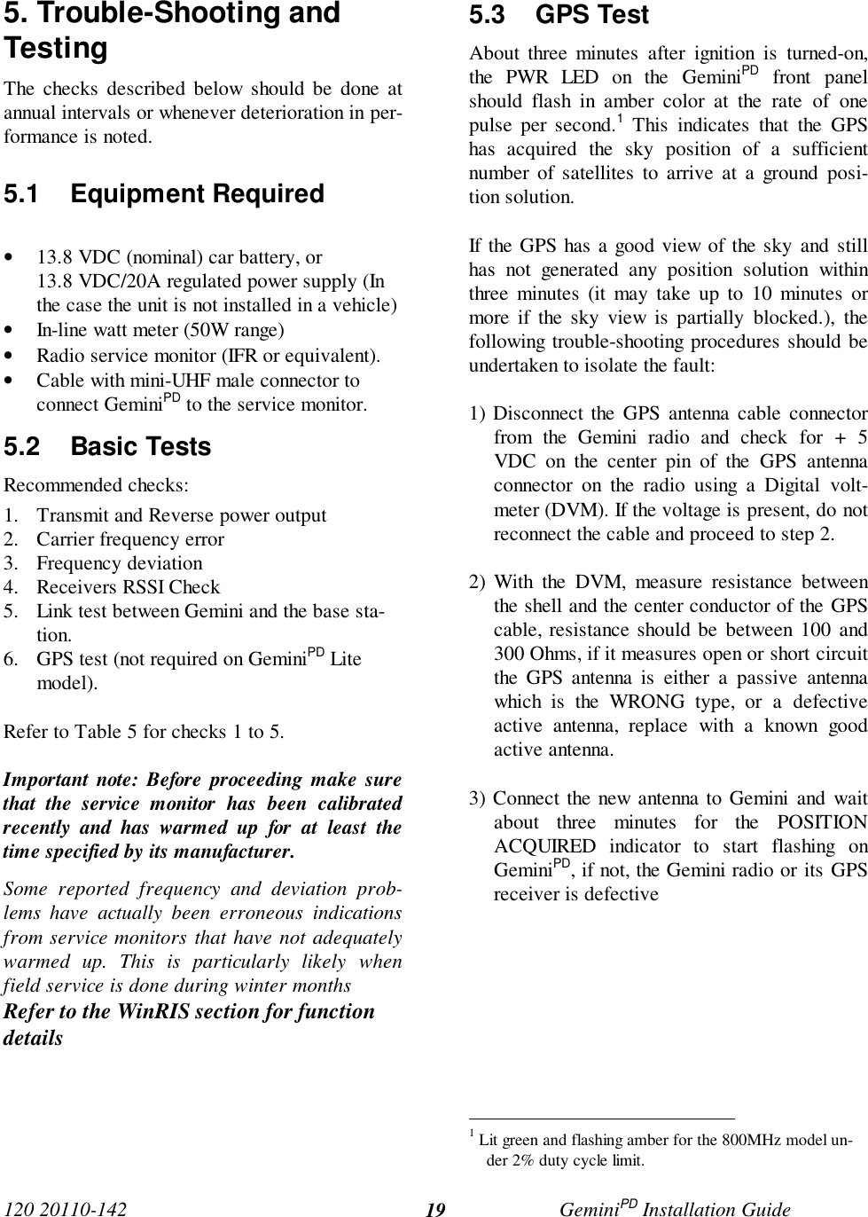
![120 20110-142 GeminiPD Installation Guide114. WinRIS programThe Windows Radio Installation Software(WinRIS) program is used to:• Check and troubleshoot GeminiPD.• Save an existing configuration.• Upload files for field-configuring units (Re-quires intervention with technical support).To run the program, you will need:A PC or portable computer running a 32-bit MS-Windows application:Win MEWin2000Win NTWin 9xNote:WinRIS does not operate under:Win CE (embedded in PocketPC)16-bit Windows 3.x- - A hard disk.- An available COM port.- A serial mouse, with its own driver installedis strongly recommend however most actionscan also be done using keyboard command4.1 OperationThis support program can be run in MS-Windows © mode.DO NOT have more than one copy of this pro-gram loaded at any given time in separate win-dows. Doing so creates COM port sharing con-flicts and failure to run the program alone resultsin unexpected transmissions.Only left mouse button operation is supported.Any command or selection shown in gray is ei-ther unavailable or is awaiting another actionbefore activating.Help in the program is available at all points bypressing the F1 key. If a subject is highlighted,the help displayed will be context sensitive.4.2 To connect and startWinRISConnect a suitable 9-conductor straight RS-232cable, between the unit’s front-mountedPC/Setup port and the RS-232 port of the PC orportable computer that will be running Gem-ini.exe program.GeminiPD’s WinRIS program is available ondiskette, Dataradio p/n 980 03392-00n.Refer to the WinRIS Readme.txtfile for details on how to setMS-Windows environment, con-nect, install and run this pro-gram.In summary, before starting the WinRIS whenrunning MS-Windows, click on “Start”, then on"Run". Type the relevant path and variables onthe command line (or select by browsing) leadingto:WinRIS.EXE COM[x], [speed],8,n,1(where x is the PC COM port to be used) Ofcourse, the executable command may be usedalone without any variable added.Click on “OK”.It is also possible to create a PC desktop short-cut icon for WinRIS:• Start by right clicking anywhere on thedesktop,• Select New,• Select Shortcut and type the path as detailedabove directly on the command line (with orwithout variables).• Click Next,• Type in an applicable name for the shortcuticon,• Click Next• Select an icon (your choice) and• Click on Finish.Command line settings override the environmentvariable, if any.](https://usermanual.wiki/CalAmp-Wireless-Networks/GPDA.Appendix-A-preliminary-version-1-42/User-Guide-147142-Page-18.png)
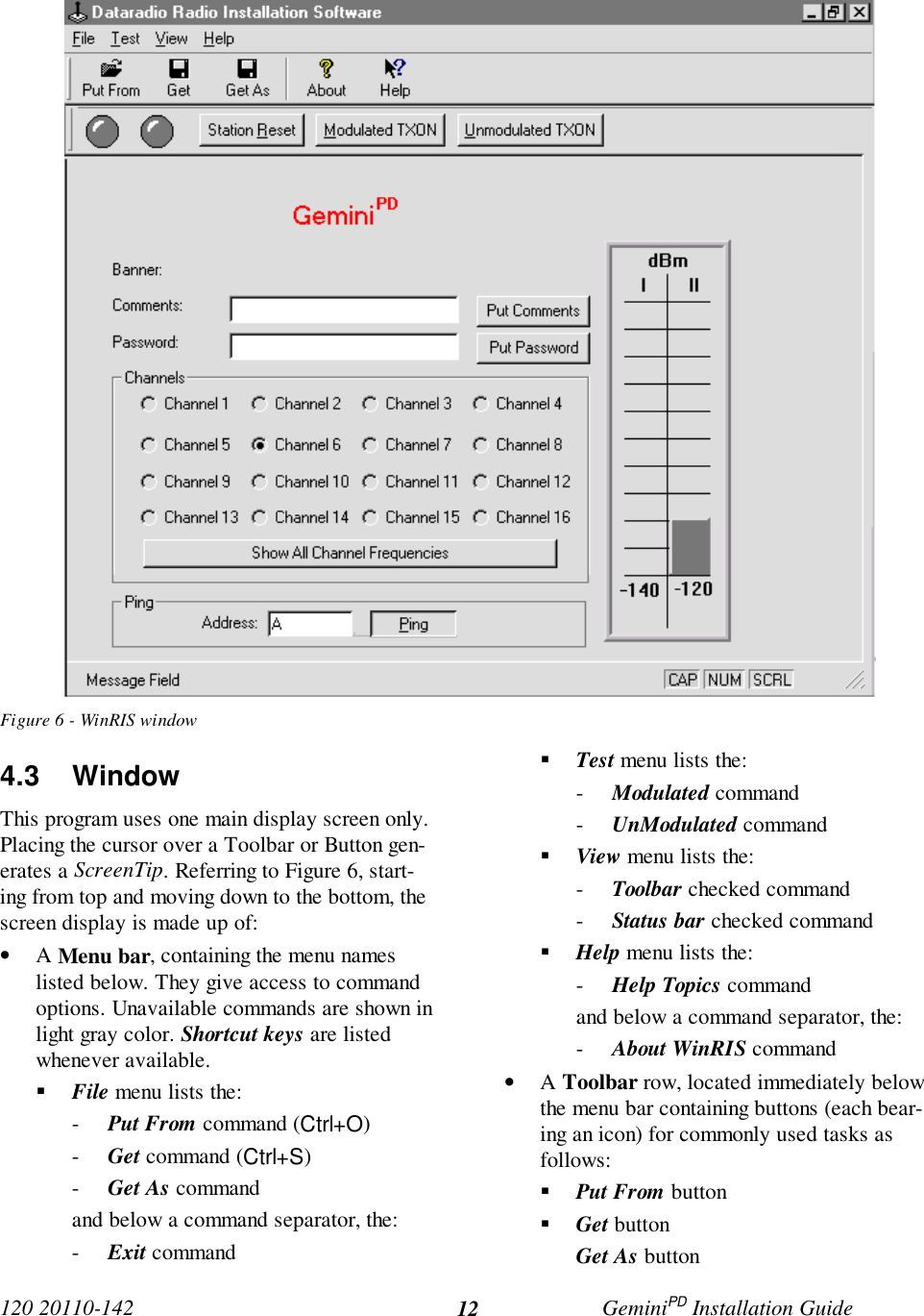
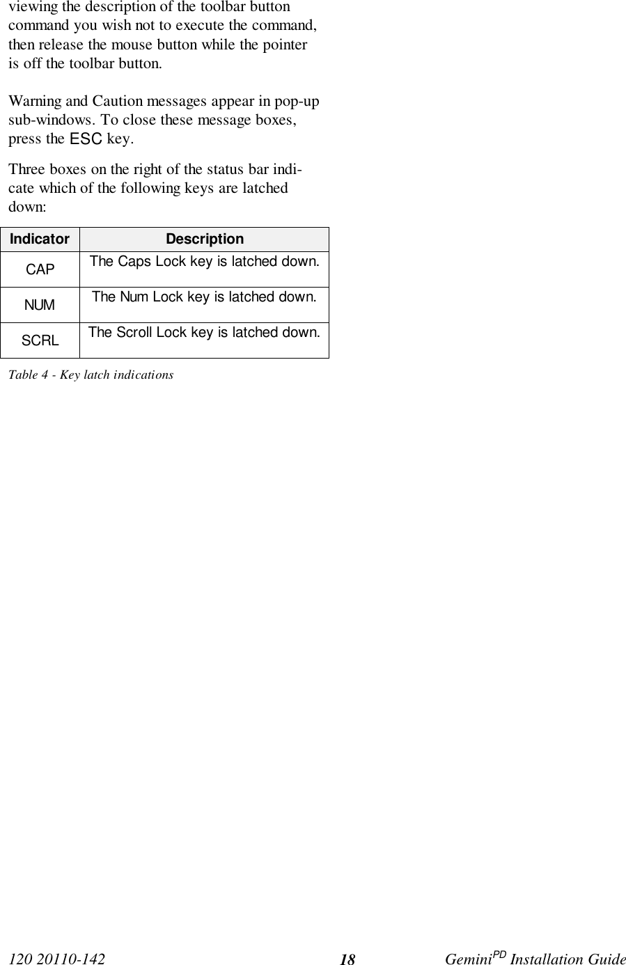
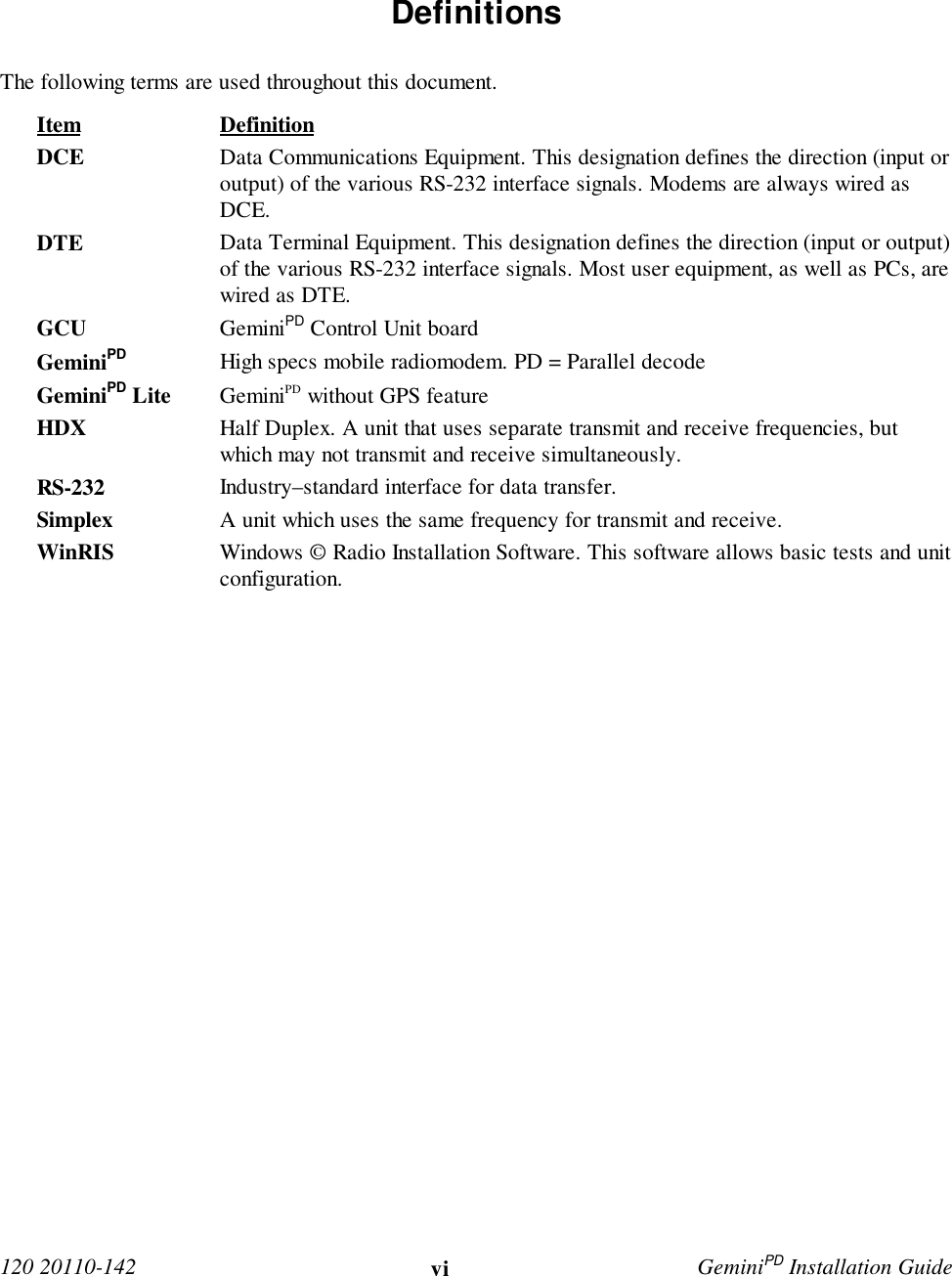
![120 20110-142 GeminiPD Installation Guide14• Download and automatically save the con-nected unit’s configuration setting to a filenamed with the unit' serial number: TheWinRIS status bar will then report “All pa-rameters are successfully retrieved andsaved in file [unit' s/n].GM2. Any previousconfiguration in the program is overwritten.If you do not wish to overwrite an existing con-figuration or prefer to name the file yourself, usethe “Get As” button.4.4.2.2 “Get As” buttonOn the menu bar, select “File”, then the “GetAs” command or press the “Get As” button onthe Toolbar to:• Establish linking• Open the “File, Save As” window with theASCII file *.gm2 (already selected).• Save the connected unit’s operating charac-teristics (configuration setting) to a file, di-rectory or drive of your choice.The program will ask before overwriting anexisting file.• Status bar reports “All parameters are suc-cessfully retrieved and saved in [filename].4.4.3 Configuration from a FileLoading a configuration from a file to a unit isuseful to:• Restore the operating characteristics of aunit (Requires intervention with technicalsupport.)• Carry out field updates using Dataradiosystem engineering supplied diskette(s).Warning:Do not make any changes tothese files. Any changes madeto the configurations MUST bedone at factory or by Dataradiosystem engineering.4.4.3.1 “Put From” button1- On the menu bar, select “File”, then the “PutFrom” command or press the “Put From”button on the Toolbar.2- In the “Open” window, locate the drive, di-rectory and file name of the relevant file.• This may be a configuration saved ear-lier from a unit.• It can also be from a Dataradio (factoryor system engineering) diskette.4- Select the appropriate file5- Press the “OK” button.The status bar reports: “[filename] isdownloading into unit” and up to 30 secondslater displays: “All parameters are saved.Apply Station Reset to take effect!” .6- Press the “Station Reset” button. See section4.4.1 for details.4.4.4 Special FunctionsThe following WinRIS fields and buttons areused to gather specific information concerningthe connected unit:• Banner field• Comments field and Put Comments button• Password and Put Password button4.4.4.1 Banner FieldThis field displays a string made up of the serialnumber of the connected unit followed by thefirmwares used and their version number.Format is:[serial number]:firmware 1 name, its version #,firmware 2 name, its version #.The serial number portion uniquely identifies theunit. It is a variable length, maximum eight-character alphabetic string assigned at the timeof manufacture. It is identical to the serial num-ber printed on the label of the unit. This numbercannot be changed and is used as part of the on-air protocol.](https://usermanual.wiki/CalAmp-Wireless-Networks/GPDA.Appendix-A-preliminary-version-1-42/User-Guide-147142-Page-21.png)