CalAmp Wireless Networks GPDA GeminiPD User Manual Appendix A preliminary version 1 42
CALAMP WIRELESS NETWORKS INC. GeminiPD Appendix A preliminary version 1 42
Contents
Appendix A preliminary version 1 42

GeminiPD
Mobile Radiomodem
Installation Guide
Version 1.42
Preliminary – For Internal Use Only
The entire contents of this manual and the Radio Installation Software
described in this manual are copyright 2000 by DATARADIO Inc.
Copyright DATARADIO Inc.
April, 2001
Part no.: 120 20110-142
Table of Contents
1. PRODUCT OVERVIEW.....................................................................................................................................1
1.1 INTENDED AUDIENCE..........................................................................................................................................1
1.2 GENERAL DESCRIPTION ......................................................................................................................................1
1.2.1 Features....................................................................................................................................................1
1.2.2 Configuration ...........................................................................................................................................1
1.3 FACTORY TECHNICAL SUPPORT..........................................................................................................................2
1.4 PRODUCT WARRANTY.........................................................................................................................................2
1.5 REPLACEMENT PARTS .........................................................................................................................................2
1.5.1 Factory Repair .........................................................................................................................................2
1.6 UNPACKING........................................................................................................................................................2
2. INSTALLATION..................................................................................................................................................3
2.1 PLANNING THE INSTALLATION ............................................................................................................................3
2.1.1 Overview...................................................................................................................................................3
2.1.2 Location....................................................................................................................................................3
2.1.3 Cable Path................................................................................................................................................3
2.2 WARNINGS .........................................................................................................................................................3
2.2.1 RF Radiation warning..............................................................................................................................3
2.2.2 Interference with vehicular electronics...................................................................................................3
2.2.3 Secure mounting.......................................................................................................................................4
2.2.4 Explosive environments............................................................................................................................4
2.2.5 Installation in vehicles powered by liquefied gas. ..................................................................................4
2.3 PHYSICAL UNIT...................................................................................................................................................4
2.3.1 Recommended tools and supplies.............................................................................................................4
2.3.2 Physical mounting of GeminiPD................................................................................................................4
2.4 ELECTRICAL INSTALLATION ................................................................................................................................5
2.4.1 Electrical requirements............................................................................................................................5
2.4.2 Routing of power cable ............................................................................................................................5
2.5 ANTENNA...........................................................................................................................................................7
2.5.1 Recommended tools and supplies.............................................................................................................7
2.5.2 Planning ...................................................................................................................................................7
2.5.3 Antenna Installation.................................................................................................................................8
2.6. COMPLETING THE PHYSICAL INSTALLATION....................................................................................................8
2.7. CHECKING OUT NORMAL OPERATION .............................................................................................................8
3. OPERATING DESCRIPTION............................................................................................................................9
3.1 FRONT & REAR PANELS......................................................................................................................................9
3.2 DTE PORT INTERFACE......................................................................................................................................10
3.2.1 RS-232 Interface Signal Levels..............................................................................................................10
4. WINRIS PROGRAM.........................................................................................................................................11
4.1 OPERATION.......................................................................................................................................................11
4.2 TO CONNECT AND START WINRIS ....................................................................................................................11
4.3 WINDOW ..........................................................................................................................................................12
4.4 FUNCTIONS.......................................................................................................................................................13
4.4.1 “Station Reset” button...........................................................................................................................13
4.4.2 Configuration to a file............................................................................................................................13
4.4.2.1 “Get” button..................................................................................................................................... 13
4.4.2.2 “Get As” button................................................................................................................................ 14
4.4.3 Configuration from a File......................................................................................................................14
4.4.3.1 “Put From” button............................................................................................................................ 14
4.4.4 Special Functions...................................................................................................................................14
4.4.4.1 Banner Field..................................................................................................................................... 14
120 20110-142 ii GeminiPD Installation Guide
4.4.4.2 Comments........................................................................................................................................ 15
4.4.4.3 Password ......................................................................................................................................... 15
4.4.5 Test Functions ........................................................................................................................................15
4.4.5.1 DSR signal is High indicator............................................................................................................... 15
4.4.5.2 CTS signal is High indicator............................................................................................................... 16
4.4.5.3 Channel Selection.............................................................................................................................. 16
RSSI & Power Out Indicators.............................................................................................................................. 16
4.4.5.5 TXON tests...................................................................................................................................... 16
4.4.5.5.1 Unmodulated Carrier..................................................................................................................... 16
4.4.5.5.2 Modulated Carrier......................................................................................................................... 17
4.4.5.6 Ping Button ...................................................................................................................................... 17
4.4.5.7 Ping addresses.................................................................................................................................. 17
4.4.6 Status Bar ...............................................................................................................................................17
5. TROUBLE-SHOOTING AND TESTING .......................................................................................................19
5.1 EQUIPMENT REQUIRED......................................................................................................................................19
5.2 BASIC TESTS.....................................................................................................................................................19
5.3 GPS TEST.........................................................................................................................................................19
6. SPECIFICATIONS.............................................................................................................................................22
FIGURE 1 - MOUNTING PLATE AND SLOT DIMENSIONS......................................................................................................5
FIGURE 2 - BRACKET INSTALLATION ................................................................................................................................5
FIGURE 3 - DC POWER CONNECTOR................................................................................................................................6
FIGURE 4 - ANTENNA SPACING ........................................................................................................................................7
FIGURE 5 - FRONT AND REAR PANELS...............................................................................................................................9
FIGURE 6 - WINRIS WINDOW.........................................................................................................................................12
FIGURE 7 - SELECT PORT WINDOW.................................................................................................................................13
FIGURE 8 - SHOW ALL CHANNEL FREQUENCY ...............................................................................................................16
TABLE 1 - GEMINIPD LEDS INDICATIONS......................................................................................................................10
TABLE 2 - RS-232 SIGNAL LEVELS ................................................................................................................................10
TABLE 3 - CARRIER MODULATION..................................................................................................................................17
TABLE 4 - KEY LATCH INDICATIONS...............................................................................................................................18
TABLE 5 - TESTS, FULL & HALF CHANNEL UNITS ..........................................................................................................20
APPENDIX 1 - "OFFICER REQUIRES ASSISTANCE" ALARM FUNCTION .......................................................................24

120 20110-142 iii GeminiPD Installation Guide
What's New in this version
History
Version 1.42 (Preliminary), April 2001
Following sections are amended to show SRRC4FSK 12.5kHz channel spacing
bit rates.
- Section 1.2.1 Features
- Table 3 Carrier Modulation
- Table 5 Tests, Full & Half Channel Units
- Section 6 Specifications
Version 1.41, March 2001
• Section 2.5 “Antenna” and Figure 4 “Antenna spacing” amended to show
FCC’s RF Exposure Guidelines for increased Duty Cycle.
Version 1.40, December 2000
• Supporting footnotes for Gemini/PD Lite model (No GPS option) added.
• Section 3.2, function of DE-9F pin 9 (Aux input) corrected and clari-
fied.
• Section 4.0, re-written to support the WinRIS program.
• Section 5.0, Table 5, step 4, values revised.
• Section 6.0, MIL Specifications limitations note added.
• Appendix 1, clarification of “Officer Requires Assistance” alarm
function added.
Version 1.32, October 2000
• Updated UHF units specifications:
- Table 3 "Carrier Modulation"
- Table 4 “Tests, Full & Half Channel Units”
- Section 6 “Specifications”.
Version 1.31, August 2000
120 20110-142 iv GeminiPD Installation Guide
• Introduction of 25.6 Kbps model. Relevant changes made to:
- Section 1.2.1 “Features”
- Table 3 “Carrier Modulation"
- Table 4 “Tests, Full & Half Channel Units”
- Section 6 “Specifications”.
- Emission designators table added to Section 6 “Specifications”.
Version 1.30, August 2000
• Power output specifications for 800MHz model added to section 1.2.1
“Features”.
• Main transceiver Output Power for 800MHz model added to:
Table 4 “Tests, Full and Half Channel Units” and minimum value edited
in the footnote.
• Title of section 4.4.4.2 edited to specify that RSSI Indicator also
serves as power meter. Note added to establish that the internal
wattmeter is not to be interpreted as a precision instrument.
• Section 4.4.4.3.1 “Unmodulated Carrier” edited to show 800MHz model
power check nominal forward wattage.
• Section 2.4.2 “Routing of Power Cable”, step no. 7, clarification of
negative wire connection.
Version 1.20, June 2000:
• LED indication explanation for the 800MHz (2% duty cycle limit) model
added as a footnote to table 1 and to section 5.3 GPS Test.
• Section 2.5 “Antenna” rewritten and now including more details con-
cerning “Planning” and has a new antenna spacing drawing.
• More details added to section 4.2 concerning starting of the WinRIS
program from MS-Windows.
• Environmental MIL spec added
• FCC Certification number added to Specifications section.
Version 1.10, March 2000:
Addition of 800MHz specifications, revision to paragraph 2.2.1 - RF Ra-
diation Warning and to paragraphs 2.5 through 2.5.3. – Antenna installa-
tion.
Version 1.0, January 2000:
First released version
120 20110-142 vGeminiPD Installation Guide

120 20110-142 vi GeminiPD Installation Guide
Definitions
The following terms are used throughout this document.
Item Definition
DCE Data Communications Equipment. This designation defines the direction (input or
output) of the various RS-232 interface signals. Modems are always wired as
DCE.
DTE Data Terminal Equipment. This designation defines the direction (input or output)
of the various RS-232 interface signals. Most user equipment, as well as PCs, are
wired as DTE.
GCU GeminiPD Control Unit board
GeminiPD High specs mobile radiomodem. PD = Parallel decode
GeminiPD Lite GeminiPD without GPS feature
HDX Half Duplex. A unit that uses separate transmit and receive frequencies, but
which may not transmit and receive simultaneously.
RS-232 Industry–standard interface for data transfer.
Simplex A unit which uses the same frequency for transmit and receive.
WinRIS Windows © Radio Installation Software. This software allows basic tests and unit
configuration.

120 20110-142 GeminiPD Installation Guide
1
1. PRODUCT OVERVIEW
This document provides the information re-
quired for the installation, operation and
verification of the DATARADIO GeminiPD
mobile radiomodem.
1.1 Intended Audience
This document is designed for use by engi-
neering design, installation, and maintenance
personnel.
1.2 General Description
GeminiPD is a mobile radiomodem aimed at
the public safety and public utility markets
to meet demand for high speed and high
throughput. It integrates all the necessary
hardware for data-only vehicular
installations up to but not including the
laptop PC and its application software.
Example of applications are:
1. Database inquiry systems.
Small number of brief messages, (usu-
ally from the mobile station) with fairly
long responses.
2. Computer-aided dispatch (CAD).
Large number of messages, (usually
from the base station) with very brief re-
sponses.
3. Automatic Vehicle Location (AVL).
Using built-in GPS receiver, determines
position, speed and direction of fleet
members.
The GeminiPD is made-up of a main
transceiver and an auxiliary receiver for
Parallel Decode (PD), a 40-Watt power
amplifier (35-Watt for 800 MHz model), a
GeminiPD Control Unit (GCU) with DSP
driven modem and an optional integrated
OEM GPS receiver. *
1.2.1 Features
• One-piece integrated design in a rugged
die-cast aluminum chassis.
• Parallel Decode (PD) technology (patent
pending) featuring dual receivers for
added decode sensitivity in multi-path
and fading environments.
• Sophisticated DSP-based modem design
provides added system performance,
fewer retries and more effective
throughput.
• Automatic channel changing for im-
proved roaming capabilities.
• Built–in, up to 16-channel flash –
EEPROM programmable synthesized
radio transceiver with automatic channel
selection.
• Models with on-air data speeds and
modulation types as follows:
- DGFSK* modulation, rates of 9600
to 19200 b/s in 12.5 or 25 kHz
channel spacing (9600 b/s maximum
in half channels).
or
- SRRC4FSK* modulation, rates of
25600 and 19200 b/s in 25 kHz or
16000 and 14400 b/s in 12.5 kHz
channel spacing.
• 3 available user ports using standard
RS-232 interface via built-in multi-
plexer.
• Half-duplex or simplex operation.
• Out-of-band signaling enables transmis-
sion of GPS* reports with no effect on
system performance.
• Back-compatible with MobilPac/R
(DGFSK)* at 9600 and 19200 b/s.
1.2.2 Configuration
GeminiPD is factory configured based on
each customer network system requirements,
usually by Dataradio System Engineering.
Configuration is not changeable in the field
without notifying Dataradio.
* Networks must use common modulation, bit
and baud rates.
* The GeminiPD Lite model has no GPS.

120 20110-142 GeminiPD Installation Guide
2
1.3 Factory Technical
Support
The Technical Support departments of
DATARADIO provide customer assistance on
technical problems and serve as an interface
with factory repair facilities. They can be
reached in the following ways:
DATARADIO Inc.
5500 Royalmount Ave, suite 200
Town of Mount Royal
Quebec, Canada H4P 1H7
Technical support hours: Monday to Friday
9:00 AM to 5:00 PM, Eastern Time
phone: +1 514 737-0020
fax: +1 514 737-7883
Email address: support@dataradio.com
or
DATARADIO Corp.
6160 Peachtree Dunwoody RD., suite C-200
Atlanta, Georgia 30328
Technical support hours: Monday to Friday
8:30 AM to 5:30 PM, Eastern Time
phone: 1 770 392-0002
fax: 1 770 392-9199
Email address: drctech@dataradio.com
1.4 Product Warranty
Warranty information may be obtained by
contacting your sales representative.
1.5 Replacement Parts
This product is not field serviceable, except
by the replacement of a complete unit. Spe-
cialized equipment and training is required to
repair the GCU board and radio modules.
Contact Technical Support for service in-
formation before returning equipment. A
Technical Support representative may sug-
gest a solution eliminating the need to return
equipment.
1.5.1 Factory Repair
When returning equipment for repair, you
must request an RMA (Returned Material
Authorization) number. The Tech Support
representative will ask you several questions
to clearly identify the problem. Please give
the representative the name of a contact per-
son who is familiar with the problem, should
questions arise during servicing of the unit.
Customers are responsible for shipping
charges for returned units. Units in warranty
will be repaired free of charge unless there is
evidence of abuse or damage beyond the
terms of the warranty. Units out of warranty
will be subject to service charges. Informa-
tion about these charges is available from
Technical Support.
1.6 Unpacking
When ready for installation, carefully unpack
your GeminiPD kit (p/n 023 6000-001) ship-
ping carton and identify each item as listed
below:
• One GeminiPD
• Installation mounting bracket
• Power cable – 22 feet (6.7 meters)
• Small parts kit
If damage has occurred to the equipment
during shipment, file a claim with the carrier
immediately.
120 20110-142 GeminiPD Installation Guide
3
2. Installation
2.1 Planning the Installation
2.1.1 Overview
To ensure trouble-free, efficient installation,
start by inspecting the vehicle to determine
the optimum position for GeminiPD and its
antennas as well as the routing of all associ-
ated cabling and wiring.
2.1.2 Location
Often, installations in cars are done in the
trunk, underneath the back window ledge or
on the trunk floor. In vans and small trucks,
it is usually done in the back of the vehicle.
In large vehicles, it is often done in the front
cabin.
Be sure to place the GeminiPD unit in such a
way that:
• The LEDs can be seen (as an aid in
troubleshooting)
• Access to the antenna DE-9 connectors
is possible without removing the unit
• Sufficient air may flow around the unit
to provide adequate cooling
GeminiPD is not fully waterproof, therefore it
should be mounted sufficiently away from an
opened trunk lid or opened tailgate, windows
or doors to avoid exposure to rain and/or
snow. It also minimizes the chance that mate-
rial can be accidentally thrown on the unit or
of someone bumping against it.
2.1.3 Cable Path
Try to route the cables away from locations
where they would be exposed to heat (ex-
haust pipes, mufflers, tailpipes, etc.), battery
acid, sharp edges, mechanical damage or
where they would be a nuisance to automo-
bile mechanics, the driver or the passengers.
Keep wiring away from automotive com-
puter modules, other electronic modules and
ignition circuits to help prevent interference
between these components and radio equip-
ment.
Try using existing holes in firewall and trunk
wall and the channels above and below or
beneath the doors, channels through doors
and window columns that are convenient to
run cables and wires.
Whenever possible, install conduit in which
to run the cables.
2.2 Warnings
Before starting installation, review all of the
following warnings.
2.2.1 RF Radiation warning
The Federal Communications Commission
(FCC), with its action in the General Docket,
79-144, March 13, 1985, has adopted a
safety standard for the human exposure to
radio frequency electromagnetic energy
emitted by FCC-regulated equipment. Only
proper installation of the transceiver antenna
of GeminiPD as summarized in section 2.5
will result in user exposure substantially
below the FCC recommended limits.
Qualified personnel must do all antenna in-
stallations. See paragraph 2.5.2 for recom-
mended antenna positioning.
Transmissions when persons or animals out-
side the vehicle are within two feet of the
antenna may result in radio energy radiation
burns or related injuries.
2.2.2 Interference with vehicular
electronics
Certain vehicle electronic devices may be
prone to malfunction due to lack of protec-
tion from radio frequency energy present
when transmitting.
It includes, and is not limited to:
- Electronic fuel injection systems
- Electronic anti-skid braking systems
- Electronic cruise control systems
120 20110-142 GeminiPD Installation Guide
4
If the installation vehicle contains such
equipment, consult the dealer for the make
of vehicle and enlist his aid in determining if
such electronic circuits will perform nor-
mally when the radio is transmitting.
2.2.3 Secure mounting
For vehicle occupant(s) safety, mount Gem-
iniPD securely so that the unit will not break
loose in case of an accident or violent ma-
neuvers.
2.2.4 Explosive environments
Operation of vehicular radio transmitters in
explosive environments may be hazardous
and conventional safety precautions must
prevail. These include and are not limited to:
- Transmitting while fuelling the vehicle.
Do not carry fuel containers in the same
compartment as GeminiPD.
- Dynamite blasting caps may explode
when transmitting radio operation takes
place within 500 feet. Always obey the
“Turn Off Two-Way Radios” signs
posted at sites where dynamite is being
used.
If transporting blasting caps:
a) Carry the blasting caps in an appropriate
metal container having a soft cushioning
lining.
b) Suppress transmissions whenever the
blasting caps container is being loaded
or unloaded into or from the vehicle.
Check applicable local bylaws.
2.2.5 Installation in vehicles
powered by liquefied gas.
GeminiPD installations in vehicles powered
by liquefied petroleum gas with the LP-gas
container in the trunk or other sealed-off
space within the interior of the vehicle must
conform to the National Fire Protection As-
sociation Standard NFPA 58 which requires:
- Space containing radio equipment shall
be isolated by a seal from the space
containing the LP-gas container and its
fittings.
- Outside filling connections shall be used
for the LP-gas container.
The LP-gas container space shall be vented
to the outside of the vehicle.
2.3 Physical Unit
2.3.1 Recommended tools and
supplies
• Electric drill for mounting holes
• Hammer and center punch
• Tie-wraps
• Drills and circle cutters as needed ac-
cording the size of screws (or nuts and
bolts) used.
• In-line “Power meter” capable of meas-
uring forward and reflected power at the
operating frequency of the radio.
2.3.2 Physical mounting of
GeminiPD
Start by running all the cables (DC power,
PC RS-232 as well as all antennas cabling)
prior to mounting GeminiPD to assure the
feasibility of the planned cable routing. Be
sure to leave sufficient slack in each cable
so the GeminiPD may be removed from the
mounting bracket for servicing with the
power applied and the antenna attached.
GeminiPD is ready for installation.
Cautions:
• When drilling mounting
holes, be careful to avoid dam-
aging some vital part of the ve-
hicle such as fuel tanks, trans-
mission housing etc. Always
check how far the mounting
screws extend below the
mounting surface prior to in-
stallation.
• Use of drill bit stops is
highly recommended.
• After drilling, remove all
metal shavings before installing
screws.
120 20110-142 GeminiPD Installation Guide
5
• Do not overtighten self-
tapping screws.
1. Once you have found a suitable mount-
ing position for GeminiPD, hold the unit
and the unattached mounting bracket in
the proposed mounting position and
check that there is clearance behind the
unit for the heatsink, cables, etc. Check
that the position provides a large enough
flat surface that the bracket will not be
distorted when installed.
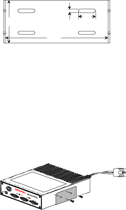
Figure 1 - Mounting plate and slot dimensions
2. Using the installation bracket as a tem-
plate, mark the four locations for drilling
(see Figure 1). Again, ensure that drilling
at the selected points is safe and will not
cause damage.
3. Indent the drilling positions with a center
punch.
4. Drill holes sized for the self-tapping
screws or for the nuts, bolts and lock
washers used.
Caution: Slightly reduce the size of the
drilled holes when using self-tapping
screws in thin metal.
Figure 2 - Bracket installation
5. Install the bracket without distorting.
6. Securely mount GeminiPD to the installed
bracket using the four supplied 8x40
black machine screws.
7. Drill any additional holes as required for
routing all cables and fit holes with
suitable grommets or bushings whenever
required.
2.4 Electrical installation
2.4.1 Electrical requirements
GeminiPD is designed to operate from a
13.8Vdc nominal car battery (negative
ground) and requires currents up to 15.0A. It
will tolerate a supply voltage range of 10.9
volts to 16.3 volts.
In vehicles with a 24 VDC electrical system
(mostly in trucks), it is essential to provide a
suitably rated 24/12 VDC converter to iso-
late the unit from the battery and protect it
against excessive voltage.
Warnings:
Application of more than 16.3 VDC
will damage GeminiPD and is not
covered by the warranty.
Always disconnect GeminiPD’s DC
power lead before connecting a
second battery, using power from
another vehicle or power boosting
(e.g. when “jump starting” the ve-
hicle).
2.4.2 Routing of power cable
1. Start by disconnecting the vehicle’s bat-
tery unless specifically prohibited from
doing so by the customer, vehicle manu-
facturer, agent or supplier.
Note:
In this event, exercise ex-
treme caution throughout
the installation and fit the
fuse only when the installa-
tion is complete.
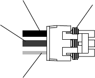
2. The 22 feet (6.7 meters) long power ca-
ble consists of three wires attached to a
Packard Electric “Weather-Pack” con-
nector (DC power Connector).
2.5"
6.0"
1.0"
0.2"
120 20110-142 GeminiPD Installation Guide
6
The DC Power connector has:
• At position “A”, the smaller red
switch-sense wire (commonly to ignition)
• At position “B”, the blue ground wire
• At position “C”, a larger red B+ DC
power wire (MUST be unswitched)
Figure 3 - DC Power Connector
3. Place this connector at GeminiPD’s radio
power input location. Do not connect at
this time. See paragraph 2.6, “Complet-
ing the physical installation”.
4. Carefully route both the B and the C
wires to where the in-line fuse holder
will be installed, usually as close to the
vehicle’s battery as practicable. Ensure
that leads do not chafe on any metal
part(s). Secure the wires at several loca-
tions along their length.
Caution:
Use proper crimping tool.
Common pliers are NOT
acceptable.
Warning:
The DC Power lead must be
unswitched
5. Insert the negative (blue) lead into one of
the appropriate connector lug and crimp
solidly to force the metal contacts onto
the wires.
6. Repeat the step above for connecting the
red DC power lead.
7. Attach the positive lead at the battery
positive terminal. Attach the negative
wire at the vehicle end of the battery
ground cable.
If the negative cable is con-
nected directly to the battery
negative terminal, it should be
fused in case of failure of the
vehicle’s ground cable.
Ensure tight and secure connections.
8. Fasten the fuse holder and leads.
9. Carefully route the A wire to where the
connection will be made for switch
sensing.
• Connect to “Ignition” if you wish to
have GeminiPD turning ON and OFF
dependent on the vehicle’s ignition
key.
• Connect to “Accessory” if you wish
GeminiPD to be available when the
engine is not running, but still de-
pendent on the ignition key.
• Connect to a user-supplied control
switch.
• In installations equipped with a
“ChargeGuard”, connect to the con-
trolled-side of the ChargeGuard
(remembering that the DC Power
lead must NOT be switched).
10. Make appropriate connections.
Cautions:
Where scraping to bare metal was
required, and at the battery posts
where wire ends and lugs may be
exposed, apply anti-corrosion com-
pound.
Insert the fuse only when installa-
tion is complete and ready to test.
11. At the GeminiPD position, neatly coil
cable slack and attach securely.
A
B
C
IGNITION
(
Small red wire
)
GROUND
(Blue wire)
13.8VDC B+
(Fused Red wire) SEAL
(DO NOT REMOVE)
120 20110-142 GeminiPD Installation Guide
7
2.5 Antenna
To meet the FCC’s RF Exposure Guidelines,
the main transmitter antenna must be vehicle-
mounted to provide a separation distance of
50 cm or more from all persons and the an-
tenna gain must not exceed 5dB to satisfy
RF exposure requirements.
2.5.1 Recommended tools and
supplies
• circle cutter
• hole saw or
• socket punch for antenna
• Mini-UHF Crimp tool
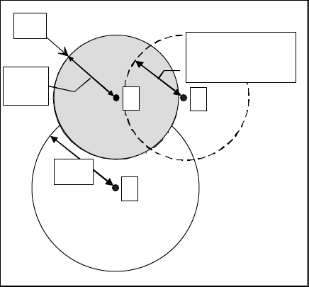
2.5.2 Planning
Referring to Figure 4, GeminiPD commonly
uses three separate antennas:
• “T” - Main transceiver -
Constraints are Maximum Permissive
Exposure (“MPE” on the drawing) limits
of 50 cm (as per see section 2.5 above)
and omni-directional factors
• “R” - Auxiliary receiver –
Constraints are the receiver spacing of at
least 5/8 λ (wavelength) from trans-
ceiver antenna and omni-directional re-
quirements
• “G” - Global Positioning System (GPS)*
Constraints are TX spacing of at least
24-in/60.96 cm from all transmitting an-
tennas and a clear view of the sky.
For the optimum antenna spacing at the fre-
quency you are using, consult System Engi-
neering.
For installation of ground-plane dependent
antennas, the center of the metal surface
used for mounting is preferable for best
omni-directional pattern.
For ground-plane independent antennas, in-
stallation may be close to the edges of the
surface.
* The GeminiPD Lite model has no GPS.
Figure 4 - Antenna spacing
Install the antennas in one of the following
positions:
- Most preferred for all antennas: center-
line of roof. For transmitter antenna, it is
the ONLY acceptable position.
- Less preferred for receiver antenna:
trunk lid, providing distance to transmit-
ting antenna is respected whether lid is
opened or closed.
- Much less preferred, but permissible for
receiver antenna: left or right rear fend-
ers, just in back of rear window
- Least preferred, but permissible for re-
ceiver antenna: left or right front fenders,
ahead of windshield
Note: Proximity to other vehicle-mounted
antennas may cause mutual inter-
ference especially at higher fre-
quencies.
G
MPE
≥
≥≥
≥5/8λ
λλ
λ
(UHF: 18"/46cm
800MHz: 9
"
/23cm)
R
T
50cm
19.7in.
≥
≥≥
≥24in.
120 20110-142 GeminiPD Installation Guide
8
2.5.3 Antenna Installation
1. Route good quality 50-ohm coaxial ca-
bles (e.g. RG-223) from each of the se-
lected antenna positions to the position
where the GeminiPD unit is mounted.
2. Terminate the end at each of the antenna
positions with the appropriate connector
for the antenna used and make the con-
nection.
3. At the GeminiPD position, cut the three
cables to length and terminate with the
appropriate plug. For the transceiver and
the auxiliary cables, use a Mini-UHF
crimp plug using an appropriate crimping
tool. For the GPS, use a SMA connec-
tor.
4. Positively identify the transceiver mini-
UHF plug and connect to the left rear of
GeminiPD.
5. Positively identify the auxiliary receiver
mini-UHF plug and connect to the front
left of GeminiPD to the RX position.
6. Connect the SMA connector to the GPS*
position below the auxiliary connector
position.
7. Do not skip this last step, trust us; it is
an important one. To complete the in-
stallation, tie-wrap together the auxiliary
and the GPS* antenna cables at a point
about two inches in front of the unit. It
will be much easier hereafter to cor-
rectly identify which mini-UHF plug
goes where. You DO NOT want to cross
the auxiliary plug with the transceiver
plug.
2.6. Completing the
physical Installation.
To complete the physical installation and
prior to testing GeminiPD:
• Connect DC Power cable’s connector to
GeminiPD’s until you hear a click as the
two parts snap together.
• Re-check that all other connections are
secure (antennas, PC, etc.)
• Switch vehicle ignition ON.
You are now ready to check for normal op-
eration and to run the Radio Installation
Software (WinRIS) program for testing or
trouble-shooting.
2.7. Checking out Normal
operation
Check that the vehicle ignition is ON.
1. Check for proper operation of the
GeminiPD’s LEDs as per Table 1 in sec-
tion 3.1
2. Using the WinRIS program (described in
section 4) and an in-line wattmeter,
check forward & reverse power to con-
firm main antenna installation.
3. Using the WinRIS, check the RF link
with a base station that can be heard by
using the WinRIS “Ping” feature (see
paragraph 4.4.4.4).
or
If user application and its base station
are available, test the installation by
going through a normal sequence of
transmitting and receiving messages.
* The GeminiPD Lite model has no GPS.
120 20110-142 GeminiPD Installation Guide
9
3. Operating Description
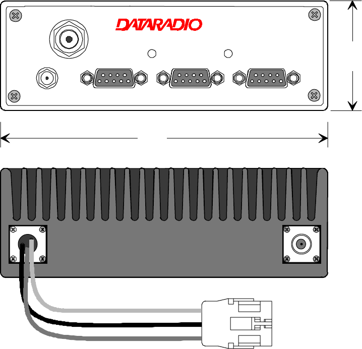
3.1 Front & Rear Panels
The front panel includes:
• One mini-UHF type female antenna connector for the auxiliary receiver
• One SMA type female connector for the GPS receiver (not installed on GeminiPD Lite model)
• Two LED indicators
• Three DE-9F RS232 ports
The rear panel includes:
• One mini-UHF type female antenna connector for the main transceiver
• One 3-pin pigtailed DC Power connector with ignition sense
Figure 5 - Front and rear panels
®
RX TXPWR PGM PC/SETUP
DEV-1DEV-2DEV-3
RX
GPS
Gemini/PD
6.000"
2.000"

120 20110-142 GeminiPD Installation Guide
10
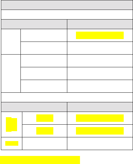
Table 1 - GeminiPD LEDs indications
GeminiPD LEDs indications
Power-on Sequence (LEDs are paired) Normal Operation (LEDs are independent)
PWR RX / TX Indication PWR Indication RX / TX Indication
Red Red Normal boot-up start
(10 to 27 sec.) Green* Normal ready state Off No network activity
Amber Off Then 8 seconds to
completing boot-up
Normal
Green Off Normal state
Amber* 1 Pulse/sec.
Sufficient satellites
acquired by GPS Green Receiving packets
“DBA sync” allows transmit
Red Off Hardware failure Amber Receiving packets
“DBA out-of-sync” prevents
transmit
Errors
Slow
Red/Green Red Software failure
(firmware erased) Red Transmitting
Special
Fast
Red/Green Red Programming in
progress
* For 800MHz model (using 25% duty cycle limit)
PWR lit Green / Flashing Amber = normal indication (GPS 1pulse per sec.)
PWR lit Amber / Flashing Green = exceeded duty cycle (GPS 1pps)
3.2 DTE Port Interface
For all three ports:
DE-9 F
pin # Function
1DCD – from GeminiPD, normally asserted
2 RXD – data from GeminiPD
3 TXD – data to GeminiPD
4 DTR – to GeminiPD, handshaking
5 Ground
6 DSR – from GeminiPD, tied to VCC
through current limiting resistor
7 RTS - to GeminiPD, handshaking
8 CTS – from GeminiPD, handshaking
9 AUX - auxiliary input to GeminiPD,
(for port 2: “Officer requires assistance”
Alarm input)
It may be activated by (normally open) dry
contact pull-up to the port’s DSR output. It
may also tolerate user pull-up to external
+12 VDC (car battery), but an isolated dry
contact is preferred due to the risk of
noise-related false alarms caused by the
vehicle’s electrical system.
A +3 to +12 V signal at this pin will send a
DMP “x” (On) message to the base.
An open or ground signal will send a DMP
“y” (Off) message.
Messages are only sent when a signal
transition occurs.
See Appendix “A” on page 24 for further
details.
We recommend the use of a shielded 9-wire ca-
ble with all pins connected. These ports can be
used for unit configuration, maintenance & ad-
justment as well to connect user applications.
3.2.1 RS-232 Interface Signal Levels
In the descriptions of data signals, the following
conventions are used:
Table 2 - RS-232 Signal Levels
Term Alternates Signal level
1 asserted, spacing +3 to +15 V
OFF dropped, marking -3 to -15 V
120 20110-142 GeminiPD Installation Guide
11
4. WinRIS program
The Windows Radio Installation Software
(WinRIS) program is used to:
• Check and troubleshoot GeminiPD.
• Save an existing configuration.
• Upload files for field-configuring units (Re-
quires intervention with technical support).
To run the program, you will need:
A PC or portable computer running a 32-bit MS-
Windows application:
Win ME
Win2000
Win NT
Win 9x
Note:
WinRIS does not operate under:
Win CE (embedded in PocketPC)
16-bit Windows 3.x
-
- A hard disk.
- An available COM port.
- A serial mouse, with its own driver installed
is strongly recommend however most actions
can also be done using keyboard command
4.1 Operation
This support program can be run in MS-
Windows © mode.
DO NOT have more than one copy of this pro-
gram loaded at any given time in separate win-
dows. Doing so creates COM port sharing con-
flicts and failure to run the program alone results
in unexpected transmissions.
Only left mouse button operation is supported.
Any command or selection shown in gray is ei-
ther unavailable or is awaiting another action
before activating.
Help in the program is available at all points by
pressing the F1 key. If a subject is highlighted,
the help displayed will be context sensitive.
4.2 To connect and start
WinRIS
Connect a suitable 9-conductor straight RS-232
cable, between the unit’s front-mounted
PC/Setup port and the RS-232 port of the PC or
portable computer that will be running Gem-
ini.exe program.
GeminiPD’s WinRIS program is available on
diskette, Dataradio p/n 980 03392-00n.
Refer to the WinRIS Readme.txt
file for details on how to set
MS-Windows environment, con-
nect, install and run this pro-
gram.
In summary, before starting the WinRIS when
running MS-Windows, click on “Start”, then on
"Run". Type the relevant path and variables on
the command line (or select by browsing) leading
to:
WinRIS.EXE COM[x], [speed],8,n,1
(where x is the PC COM port to be used) Of
course, the executable command may be used
alone without any variable added.
Click on “OK”.
It is also possible to create a PC desktop short-
cut icon for WinRIS:
• Start by right clicking anywhere on the
desktop,
• Select New,
• Select Shortcut and type the path as detailed
above directly on the command line (with or
without variables).
• Click Next,
• Type in an applicable name for the shortcut
icon,
• Click Next
• Select an icon (your choice) and
• Click on Finish.
Command line settings override the environment
variable, if any.
120 20110-142 GeminiPD Installation Guide
12
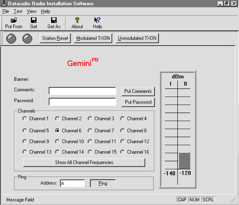
Figure 6 - WinRIS window
4.3 Window
This program uses one main display screen only.
Placing the cursor over a Toolbar or Button gen-
erates a ScreenTip. Referring to Figure 6, start-
ing from top and moving down to the bottom, the
screen display is made up of:
• A Menu bar, containing the menu names
listed below. They give access to command
options. Unavailable commands are shown in
light gray color. Shortcut keys are listed
whenever available.
! File menu lists the:
- Put From command (Ctrl+O)
- Get command (Ctrl+S)
- Get As command
and below a command separator, the:
- Exit command
! Test menu lists the:
- Modulated command
- UnModulated command
! View menu lists the:
- Toolbar checked command
- Status bar checked command
! Help menu lists the:
- Help Topics command
and below a command separator, the:
- About WinRIS command
• A Toolbar row, located immediately below
the menu bar containing buttons (each bear-
ing an icon) for commonly used tasks as
follows:
! Put From button
! Get button
Get As button

120 20110-142 GeminiPD Installation Guide
13
and to the right of a bar separator, the:
! About button and the
! Context-sensitive Help button
• An Indicator and Button bar, located im-
mediately below the Toolbar row, it contains
two circular indicators
! DSR signal is High indicator
! CTS signal is High indicator
and three buttons for commonly used tasks as
follows.
! Station Reset button
! Modulated TXON button
! Unmodulated TXON button
• A Product field, displays product type be-
ing used after a connection to the product
has been established
• A Data section, containing the Banner plus
the Comments and Password fields and their
related Put buttons.
• A Channel(s) section, to select and activate
a channel.
• A Test section, with a Ping button and the
relevant address field.
• A Status bar, for displaying standard user-
messages. Other messages appear in dialog
window boxes or warning windows.
4.4 Functions
The WinRIS program is used to:
• Save an existing configuration from a unit to
a file.
• Take a configuration from a file and upload
it to a unit
• Check GeminiPD
• Test and/or trouble-shoot installations
4.4.1 “Station Reset” button
The Station Reset button is the only button
available when first starting the program and is
used to initiate the connection process.
• Press Station Reset.
• Enter Port and Baud rate information in the
Select Port sub-window.
Figure 7 - Select Port window
• Press OK to validate the selection (or Can-
cel to exit back to the main screen).
• All test buttons and fields are now activated.
The Station Reset button is also pressed as a last
step after doing a “Put From”. The Station Reset
button causes downloaded parameters from a file
or diskette to take effect in the connected unit.
Pressing Station Reset is not required after doing
any Comments or Password configuration change
as these have their own Put Comments and Put
Password buttons.
Station Reset does not break the connection.
4.4.2 Configuration to a file
Saving the unit’s configuration to a file allows
the user to:
• Subsequently restore the configuration.
• Safeguard a copy as documentation of the
configuration.
Note: The configuration and status files are
ASCII files and may be e-mailed or faxed to
technical support when requested to do so.
Warning:
Do not make any changes to these files. Any
changes made to the configurations MUST be
done at factory or by Dataradio system
engineering.
4.4.2.1 “Get” button
On the menu bar, select “File”, then the “Get”
command or press the “Get” button on the Tool-
bar to:
• Establish linking
120 20110-142 GeminiPD Installation Guide
14
• Download and automatically save the con-
nected unit’s configuration setting to a file
named with the unit' serial number: The
WinRIS status bar will then report “All pa-
rameters are successfully retrieved and
saved in file [unit' s/n].GM2. Any previous
configuration in the program is overwritten.
If you do not wish to overwrite an existing con-
figuration or prefer to name the file yourself, use
the “Get As” button.
4.4.2.2 “Get As” button
On the menu bar, select “File”, then the “Get
As” command or press the “Get As” button on
the Toolbar to:
• Establish linking
• Open the “File, Save As” window with the
ASCII file *.gm2 (already selected).
• Save the connected unit’s operating charac-
teristics (configuration setting) to a file, di-
rectory or drive of your choice.
The program will ask before overwriting an
existing file.
• Status bar reports “All parameters are suc-
cessfully retrieved and saved in [filename].
4.4.3 Configuration from a File
Loading a configuration from a file to a unit is
useful to:
• Restore the operating characteristics of a
unit (Requires intervention with technical
support.)
• Carry out field updates using Dataradio
system engineering supplied diskette(s).
Warning:
Do not make any changes to
these files. Any changes made
to the configurations MUST be
done at factory or by Dataradio
system engineering.
4.4.3.1 “Put From” button
1- On the menu bar, select “File”, then the “Put
From” command or press the “Put From”
button on the Toolbar.
2- In the “Open” window, locate the drive, di-
rectory and file name of the relevant file.
• This may be a configuration saved ear-
lier from a unit.
• It can also be from a Dataradio (factory
or system engineering) diskette.
4- Select the appropriate file
5- Press the “OK” button.
The status bar reports: “[filename] is
downloading into unit” and up to 30 seconds
later displays: “All parameters are saved.
Apply Station Reset to take effect!” .
6- Press the “Station Reset” button. See section
4.4.1 for details.
4.4.4 Special Functions
The following WinRIS fields and buttons are
used to gather specific information concerning
the connected unit:
• Banner field
• Comments field and Put Comments button
• Password and Put Password button
4.4.4.1 Banner Field
This field displays a string made up of the serial
number of the connected unit followed by the
firmwares used and their version number.
Format is:
[serial number]:firmware 1 name, its version #,
firmware 2 name, its version #.
The serial number portion uniquely identifies the
unit. It is a variable length, maximum eight-
character alphabetic string assigned at the time
of manufacture. It is identical to the serial num-
ber printed on the label of the unit. This number
cannot be changed and is used as part of the on-
air protocol.
120 20110-142 GeminiPD Installation Guide
15
GeminiPD's firmwares resides in flash EPROM
and are designed to allow field upgrades.
When contacting your supplier, give the full ban-
ner string and the version of the WinRIS used.
You will find the version number by selecting
the “Help” menu option, then “About WinRIS”
command or pressing the “About” button on the
Toolbar.
The “Banner” field is blank prior to doing a
"Get", "Get As" or "Put From".
4.4.4.2 Comments
1- Type comments directly in the “Comments”
field. These can be text up to 24 characters.
Use this field to enter user-convenient de-
scription(s) (customer name, location,
etc…).
2- Press the button “Put Comments” to make
the entry permanent. This field may be left
blank.
On subsequent “Get”, “Get As” or “Put From”,
this field displays entered comments. If no com-
ment was entered, the field will remain blank.
4.4.4.3 Password
The password feature is useful where two (or
more) fleets share the same radio channel. Mo-
biles without the proper password would still
receive the message but the contents would not
be intelligible.
1- Type your password directly in the “Pass-
word” field. It is a string of 32 hexadecimal
characters (exactly).
2- Press the button “Put Password” to make the
entry permanent. This field may be left
blank.
On subsequent “Get”, “Get As” or “Put From”,
this field will require that the correct password
be entered. If none was entered, the field will
remain blank.
Password information is NOT retrieved and
saved to a file, along with the configuration.
Clearing a Password is done by entering 32 zeros.
The Dataradio supplied password algorithm is
designed to thwart the casual observer only. It
provides a limited form of data privacy. There-
fore, if your security requirements are high, Da-
taradio urges you to use external encryption
technology (such as Data Encryption Standard
(DES)) in the Host and Mobiles computers.
4.4.5 Test Functions
The following WinRIS functions and buttons are
used to carry out testing or trouble-shooting on a
connected unit:
• DSR signal is High indicator
• CTS signal is High indicator
• Channels select
• Show All Channel Frequencies
• RSSI Indicator
• TXON (Modulated)
• TXON (Unmodulated)
• Ping Address and Ping button
4.4.5.1 DSR signal is High indicator
The “Data Set Ready” (DSR) indicator light,
located on the button bar (leftmost), is an RS-
232 protocol port indication. When lit, it indi-
cates proper connection and that the value is
High. The DMP protocol used requires that DSR
be normally asserted.
120 20110-142 GeminiPD Installation Guide
16
4.4.5.2 CTS signal is High indicator
The “Clear-to-Send” (CTS) indicator light, lo-
cated on the button bar (second indicator from
the left), is an RS-232 protocol port indication.
When lit, it indicates proper connection and that
the value is High. The DMP protocol used re-
quires that CTS be normally asserted.
4.4.5.3 Channel Selection
Select the radio channel on which you wish to
send a test transmission by clicking the relevant
available option button.
The program automatically detects which of
sixteen channels are present on the connected
unit. For each factory-set channel available, the
relevant round option button and channel number
is enabled (black). For each unavailable channel,
the round option button and channel number ap-
pears disabled (grayed-out). Only one channel at
a time may be selected.
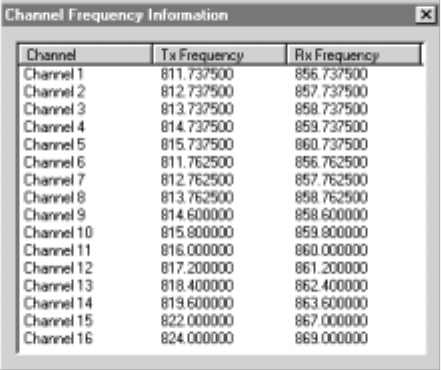
Pressing the “Show All Channel Frequencies”
button opens a sub-window (see Figure 8) listing
in tabular form the radio transmitting and re-
ceiving frequencies programmed for each avail-
able channel(s).
To exit this sub-window, press the upper right
system box.
Figure 8 - Show All Channel Frequency
4.4.5.4 RSSI & Power Out Indicators
The Radio Signal Strength Indicator (RSSI) bar
graph usually displays in twin-columns the rela-
tive strength (in dBm) of an incoming RF signal
on the selected channel.
The left column indication, labeled "I", shows
the transceiver RX signal (rear mini-UHF con-
nector).
The right column indication, labeled "II", shows
the auxiliary RX signal (front mini-UHF connec-
tor).
Meter precision is usually better than 3 dBm.
This indicator functions as a single column
"Power" (Watt) meter when using either of the
test functions: "TXON (Modulated)" or "TXON
(Unmodulated)" with a range of 0 to 60 watts.
Precision is usually better than +/-3 watts.
Note: This internal wattmeter is designed for
use as reference only and is not a sub-
stitute for a quality external precision
measuring instrument.
4.4.5.5 TXON tests
TXON test functions are selected by choosing
“Test” from the file menu, then “Modulated” or
“UnModulated” command or by pressing the
relevant button on the Toolbar.
4.4.5.5.1 Unmodulated Carrier
Unmodulated carrier gives a clear carrier and is
frequently used for checking:
• Frequency error
• Forward and reverse power
Press the TXON (Unmodulated) button to trans-
mit an unmodulated 20-seconds test signal on the
channel selected or until the button is pressed
again.
The functions of all the other buttons are inop-
erative during test transmissions.
Power check:
1- Connect an in-line power meter between the
radio and the antenna.
2- Measure the forward (nominal 40W for UHF
model and 35W for 800MHz model) and re-
flected power levels by powering TX ON
120 20110-142 GeminiPD Installation Guide
17
(<5% of forward power or as specified by
System Eng.).
4.4.5.5.2 Modulated Carrier
Test transmission generates a carrier modulated
with 1kHz sinewave, at deviation level that de-
pends on model and network speed:
Table 3 - Carrier Modulation
Carrier Modulation
Full Channel
Network Speed Typical Deviation
25600 ± 4.01)/±3.72) kHz
SRRC
4FSK
19200 ± 4.5 kHz
19200 ± 4.0 kHz
16000 ± 4.0 kHz
DGMSK
9600 ± 3.0 kHz
Half Channel
Network Speed Typical Deviation
16000 ± 1.91)/±2.42) kHz
SRRC
4FSK
14400 ± 2.31)/±2.72) kHz
DGMSK 9600 ± 2.5 kHz
Different modulation types are not interoperable
1) UHF model 2) 800MHz model
This function is frequently used for checking
frequency deviation.
Press the TXON (Modulated) button to begin
transmitting a 20-seconds modulated test signal
on the channel or until the button is pressed
again.
The functions of all the other buttons are inop-
erative during test transmissions.
4.4.5.6 Ping Button
The Ping function checks connectivity by testing
the ability of GeminiPD to communicate with the
base station by sending a short transmission
query and receiving a confirming response.
1- Specify the channel (paragraph 4.4.5.3) and
ping address (paragraph 4.4.5.7)
2- Press the Ping button to start ping testing.
The functions of all the other buttons are inop-
erative during pinging.
The program sends a test query and continues
transmitting pings at brief intervals.
As soon as a Ping test signal is returned from the
address selected, the status bar displays:
• “Ping Successful” and pinging stops.
• If no ping signal is received after 60 sec-
onds, ping testing stops and the status bar
displays “Ping Failed”.
4.4.5.7 Ping addresses
Addresses may be entered by typing directly in
the “Ping Address” field in two ways:
1. Numerically, the valid address range is
1-126.
2. As an “Alpha-Mapped-Nibble” (AMN) ad-
dress, consisting of upper case letters in the
range A-P. The valid address range is A to
GN.
The base address is usually: 1.
The program may display one of the following
messages on the status bar:
For ParagonPD product:
“Ping address is not in AMN or number format”
or
For GeminiPD product:
“Ping address is not in the range A – GN”
In either case, check that the address entered is
within the acceptable range, is of a valid format
and correctly typed.
4.4.6 Status Bar
The Status Bar is located along the bottom edge
of the WinRIS window. To display or hide the
bar, check or uncheck the command in the
“View” menu.
The left area of the status bar describes actions
of menu items as you navigate using the direc-
tional arrows. This area also shows messages
describing actions of toolbar buttons as you de-
press them, before releasing them. If after

120 20110-142 GeminiPD Installation Guide
18
viewing the description of the toolbar button
command you wish not to execute the command,
then release the mouse button while the pointer
is off the toolbar button.
Warning and Caution messages appear in pop-up
sub-windows. To close these message boxes,
press the ESC key.
Three boxes on the right of the status bar indi-
cate which of the following keys are latched
down:
Indicator Description
CAP The Caps Lock key is latched down.
NUM The Num Lock key is latched down.
SCRL The Scroll Lock key is latched down.
Table 4 - Key latch indications

120 20110-142 GeminiPD Installation Guide
19
5. Trouble-Shooting and
Testing
The checks described below should be done at
annual intervals or whenever deterioration in per-
formance is noted.
5.1 Equipment Required
• 13.8 VDC (nominal) car battery, or
13.8 VDC/20A regulated power supply (In
the case the unit is not installed in a vehicle)
• In-line watt meter (50W range)
• Radio service monitor (IFR or equivalent).
• Cable with mini-UHF male connector to
connect GeminiPD to the service monitor.
5.2 Basic Tests
Recommended checks:
1. Transmit and Reverse power output
2. Carrier frequency error
3. Frequency deviation
4. Receivers RSSI Check
5. Link test between Gemini and the base sta-
tion.
6. GPS test (not required on GeminiPD Lite
model).
Refer to Table 5 for checks 1 to 5.
Important note: Before proceeding make sure
that the service monitor has been calibrated
recently and has warmed up for at least the
time specified by its manufacturer.
Some reported frequency and deviation prob-
lems have actually been erroneous indications
from service monitors that have not adequately
warmed up. This is particularly likely when
field service is done during winter months
Refer to the WinRIS section for function
details
5.3 GPS Test
About three minutes after ignition is turned-on,
the PWR LED on the GeminiPD front panel
should flash in amber color at the rate of one
pulse per second.1 This indicates that the GPS
has acquired the sky position of a sufficient
number of satellites to arrive at a ground posi-
tion solution.
If the GPS has a good view of the sky and still
has not generated any position solution within
three minutes (it may take up to 10 minutes or
more if the sky view is partially blocked.), the
following trouble-shooting procedures should be
undertaken to isolate the fault:
1) Disconnect the GPS antenna cable connector
from the Gemini radio and check for + 5
VDC on the center pin of the GPS antenna
connector on the radio using a Digital volt-
meter (DVM). If the voltage is present, do not
reconnect the cable and proceed to step 2.
2) With the DVM, measure resistance between
the shell and the center conductor of the GPS
cable, resistance should be between 100 and
300 Ohms, if it measures open or short circuit
the GPS antenna is either a passive antenna
which is the WRONG type, or a defective
active antenna, replace with a known good
active antenna.
3) Connect the new antenna to Gemini and wait
about three minutes for the POSITION
ACQUIRED indicator to start flashing on
GeminiPD, if not, the Gemini radio or its GPS
receiver is defective
1 Lit green and flashing amber for the 800MHz model un-
der 2% duty cycle limit.

120 20110-142 GeminiPD Installation Guide
20
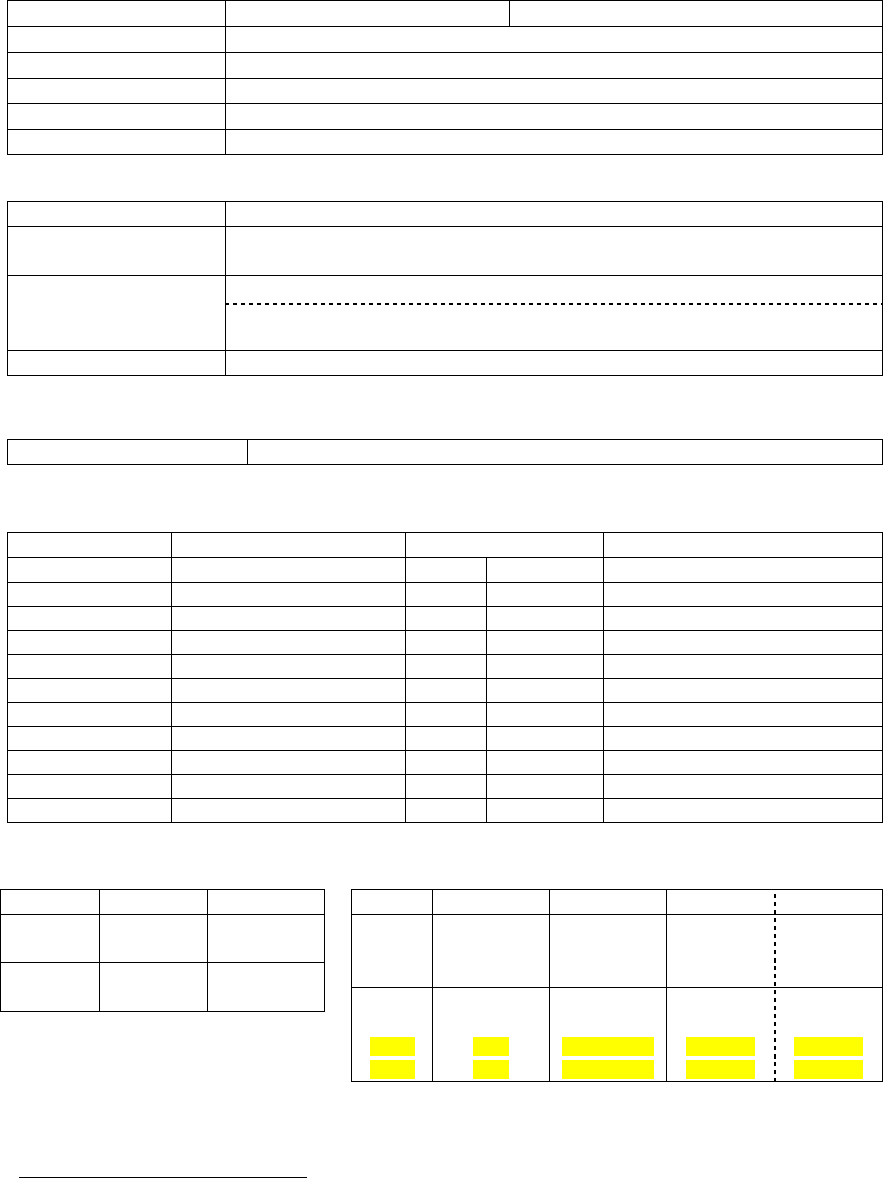
Table 5 - Tests, Full & Half Channel Units
CHECKLIST
STEP ACTION EXPECTED RESULTS at 25°
°°
°CMEASURE WITH IF NOT?
GeminiPD units are set and characterized at the factory to optimize performances. It is not recommended to try to readjust the units.
1Power-up LED
Sequence as per Table 1 - GeminiPD LEDs indications
2Connect and save con-
fig
Press WinRIS Get button
as per section 4.4.2
3Main transceiver Out-
put Power
Press TX (Unmod)
UHF: 40 watts
800MHz: 35 watts
both +10%, -10%
Factory-settable down to 10
watts (5 watts for 800MHz
model) as per customer request
Service monitor set to
read power
or
50W in-line wattmeter
Refer to factory technical
support.
4Main transceiver
Reflected Power
Press TXON (Unmod)
<5% of forward power or as
specified by System Eng. 10W in-line wattmeter Check for bad connec-
tions, damaged coax
cable, etc.
5Carrier Frequency Er-
ror
Press TX (Unmod)
±300 Hz Service monitor set to
read frequency error Refer to factory technical
support.
SRRC4FSK, Full ch. unit:
25.6 kb/s: ±4.0 kHz (UHF)
±3.7 kHz (800MHz)
19.2 kb/s: ±4.5 kHz
SRRC4FSK, Half ch. unit:
16.0 kb/s: ±1.9 kHz (UHF)
±2.4 kHz (800MHz)
14.4 kb/s: ±2.3 kHz (UHF)
±2.7 kHz (800MHz)
Service monitor set to
read deviation
(IF filter set to Mid or
30 kHz position) Refer to factory technical
support.
4TX Deviation
Press
TXON (Modulated)
Carrier will be modulated
with a 1 kHz tone.
DGFSK, Full ch. unit:
19.2 and 16 kb/s: ±4.0 kHz
9.6 kb/s: ±3.0 kHz
DGFSK, Half ch. unit:
9.6 kb/s: ±2.5 kHz
Tolerance is +5%, -10% for all bit
rates.
5RF Link test
"Ping" a base station “Ping Successful” as per section
4.4.5.6
Check on the WinRIS RSSI bar
graph if the base station is within
range (i.e. better than -107dBm)
or
Refer to factory technical support.
6 Set the service monitor to generate at the levels mentioned below. The carrier generated should be modulated with
a 1.0 kHz tone at deviation of +/- 4.0kHz (full ch.) or +/-2.5kHz (half ch.).
7Main Receiver
RSSI checks
-70dBm
-110dBm
-120dBm
- 70 dBm +/-3
-110 dBm +/-3
-120 dBm +/- 3
WinRIS bar graph
Refer to factory technical
support.
The RSSI checks give a
good indication of re-
ceivers' health.

120 20110-142 GeminiPD Installation Guide
21
8Aux Receiver
repeat as per step 7 same as step 7 WinRIS bar graph Refer to factory technical
support.
1 (unless you have set a lower value). Note that readings less than 40 watts (UHF model) or 35 watts (800MHz model) may be due to
losses in cables used for testing. Check also your wattmeter frequency calibration curve. Do not be too ready to condemn the trans-
mitter.

120 20110-142 GeminiPD Installation Guide
22
6. Specifications
GENERAL
UHF 800 MHz
Frequency Tx 403 - 512 MHz1806 – 824 MHz (821-824)
Frequency Rx 403 - 512 MHz 1851 – 869 MHz (866-869)
Channel spacing 12.5 or 25 kHz
Frequency Control Digital Synthesizer / uController
Frequency Stability 1.5 ppm
Operating temperature -30°C to +60°C (25°C nominal) @ 95% non-cond. RH
Modes of Operation Simplex or Half Duplex
Number of channels 16 internally stored
Supply voltage 13.6Vdc nominal (negative ground)
10.9 – 16.3 VDC
Circuit Protection 15 Amp fuse external
2 & 4 Amp fuse internal
RX Current at 13.6 VDC < 550 mA Standby (with auxiliary receiver)
TX Current at 13.6 VDC < 15 A
TX/RX separation 5 MHz typical
Nominal Dimensions 7.050” D x 6.000” W x 2.0000” H
Weight: < 3.5 lbs.
RF input/output Impedance 50 ohms nominal
RF connector Main TX/RX: mini-UHF female
Auxiliary RX: mini-UHF female
GPS RX: SMA female (Not installed for GeminiPD Lite version)
Interface connector 3x DE-9F D-subminiature
RECEIVER
Sensitivity (12 dB SINAD) < 0.35 µV *
Selectivity (25KHz) 75 dB typical
70 dB minimum
Selectivity (12.5) 65 dB typical
60 dB minimum
Intermodulation 75 dB typical
70 dB minimum
Spurious rejection 75 dB typical
70 dB minimum
FM hum & noise -45 dB typical *
Conducted spurious < -57 dBm
* psophometrically weighted filter
1 WARNING: The frequency band 406 to 406.1 MHz is reserved for use by distress beacons
and should not be programmed into the unit.
120 20110-142 GeminiPD Installation Guide
23
TRANSMITTER
Power output UHF = 10-40 watts 800 MHz = 5-35 watts
Duty cycle 20% @ full power, 30 secs. max. TX time (subject to FCC MPE limit)
Conducted Spurious -75 dBc (-38 dBm @10 W) typical
Frequency stability 1.5 ppm
FM hum and noise -45 dB max (25 kHz)
Attack time < 10 ms
Operation Simplex/half duplex
Data rates and
Modulation type
DGFSK (9600 b/s), (19200 b/s) *
SRRC4FSK (19200 b/s), (25600 b/s) *
better than –112 dBm at 19200 b/s full channel, with P/D (DGFSK)*
Packet Error Rate
(for < 1% error) better than –110 dBm at 25600 b/s full channel, with P/D (SRRC4FSK - UHF)*
better than –109 dBm at 25600 b/s full channel, with P/D (SRRC4FSK – 800MHz)*
Protocol Dataradio Proprietary DBA
* Networks must use common modulation, bit and baud rates. Different types are not on-air compatible
DISPLAY and CONTROLS
2 status LEDs RX/TX, PWR
Environmental MIL. spec.
Environment Categories MIL Spec. 810E Other
Method Procedure
Low Pressure Operations 500.3 II
High Temperature Operations, Storage 501.3 I(A1), II
Low Temperature Operations, Storage 502.3 I(C3), II (C1)
Temperature Shock Transfer of equipment 503.3 I(AI,C2)
Solar Radiation Heat effects 505.3 I
Rain1Drip rain 506.3 II IEC IP54 only II
Humidity1Induced, Aggravated 507.3 II,III
Dust1Blowing dust 510.3 I IEC IP54
Vibration Ground Mobile 514.4 I(8) EIA RS-204C Forestry
Shock Functional, Bench handling 516.4 I,VI EIA RS-204C
FCC / IC CERTIFICATIONS EMISSION DESIGNATORS
FCC IC (DOC) Bit rate Baud rate Modulation UHF 800MHz
UHF EOTGPDA 773195525A 9600 9600 DGMSK 8K60FID 8K60FID
16000 16000 DGMSK 15K3FID 15K3FID
800 MHz EOTGPDB 773195643A 19200 19200 DGMSK 15K0FID 15K0FID
19200 9600 SRRC4FSK* 16K0FID 16K0FID
25600 12800 SRRC4FSK* 15K6F1D 15K6FID
16000 8000 SRRC4FSK* 8K17F1D 10K0F1D
14400 7200 SRRC4FSK* 8K67F1D 11K0F1D
* IC – Class II permissive change
1 MIL Specification not guaranteed with GeminiPD Lite version.
120 20110-142 GeminiPD Installation Guide
24
Appendix 1 - "Officer Requires Assistance" alarm function
The contents of this appendix are also available as Technical Instruction Sheet 009 (TIS009),
document part number 122 20110-009 dated December 20, 2000.
Overview
The DTE Port Interface pin 9 (AUX) on DEV-2 is used for the “Officer Requires Assistance”
alarm function.
Intended Audience
This document is designed for use by System Integrators.
Physical Connection
This auxiliary input may be activated by (normally open) dry contact pull-up to the port’s DSR
output. It can also tolerate user pull-up to external +12 VDC (car battery), but an isolated dry
contact is preferred due to the risk of noise-related false alarms caused by the vehicle’s electrical
system.
A +3 to +12 V signal at this pin will send a DMP “x” (On) message to the base.
An open or ground signal will send a DMP “y” (Off) message.
Messages are only sent when a signal transition occurs (debounced for approximately 100 ms).
Operation
When using GeminiPD or GeminiPD Lite products, activating the “Officer Requires Assistance”
alarm input starts emergency communications:
• The modem creates DMP “x” or “y” messages.
• Any other pending message(s) will be failed to avoid delaying the alarm message on account
of lower priority traffic and to remove non-emergency messages from duty-cycle management
(if applicable). In the case of a “q” message, a D-NAK* will be immediately returned.
• Base and Channel hunt will take place for the usual number of retries per base (according to
configuration) but will cycle forever until D-ACKed* or Reset*.
• Lack of base DBA synch will not prevent transmission to maximize the chance that a base
gets the alarm signal. DBA “Freewheel” mode will be forced until the alarm is acknowledged.
* For details on DMP terms, refer to DMP 1.5 manual, version 4.0