CalAmp Wireless Networks GPDB Gemini/PD User Manual preliminary version of
CALAMP WIRELESS NETWORKS INC. Gemini/PD preliminary version of
Contents
- 1. preliminary version of user manual
- 2. Installation Guide 1 01
- 3. revised pages 7 and 8 for preliminary ver1 11
- 4. installation guide
- 5. Annex B Installation manual
- 6. Appendix A preliminary version 1 42
- 7. preliminary installation manual
- 8. preliminary version
- 9. preliminary updated user manual
- 10. preliminary version of updated installation manual
- 11. updated user manual
preliminary version of user manual

Gemini / PD
Mobile Radio Modem
Service Manual
version 0.03
PRELIMINARY
The entire contents of this manual and the Radio Service Software
described in this manual are copyright 1998 by DATARADIO Inc.
Copyright DATARADIO Inc.
November 1998
part no.: 120 1020110-003
i
Table of Contents
1. PRODUCT OVERVIEW................................................................................................................................... 1
1.1 INTENDED AUDIENCE ....................................................................................................................................... 1
1.2 GENERAL DESCRIPTION .................................................................................................................................... 1
1.3 CONFIGURATION ............................................................................................................................................... 1
1.4 FACTORY TECHNICAL SUPPORT........................................................................................................................ 2
1.5 PRODUCT WARRANTY ...................................................................................................................................... 2
1.6 REPLACEMENT PARTS....................................................................................................................................... 2
1.6.1 Factory Repair........................................................................................................................................ 2
2. OPERATION...................................................................................................................................................... 2
2.1 FRONT & REAR PANELS ................................................................................................................................... 2
2.1.1 LED Indicators........................................................................................................................................ 3
2.2 DTE PORT INTERFACE ..................................................................................................................................... 3
2.2.1 RS-232 Interface Signal Levels............................................................................................................... 3
3. ADJUSTMENTS AND MAINTENANCE....................................................................................................... 4
3.1 OVERVIEW........................................................................................................................................................ 4
3.1 INTENDED AUDIENCE ....................................................................................................................................... 4
3.2 EQUIPMENT REQUIRED ..................................................................................................................................... 4
3.3 MAINTENANCE INTERVALS............................................................................................................................... 4
3.4 TESTS & ADJUSTMENTS ................................................................................................................................... 4
3.4.1 Preliminary Verification ......................................................................................................................... 4
3.4.2 Basic Tests & adjustments....................................................................................................................... 4
3.4.3 Tests & adjustments Procedure............................................................................................................... 4
3.4.4 Opening the Unit..................................................................................................................................... 6
3.4.5 GPS Diagnostics Procedure.................................................................................................................... 7
4. SPECIFICATIONS............................................................................................................................................ 8

ii
What's New in Version 0.02
GPS Diagnostics procedure
History
Version 0.1: First preliminary version
Version 0.2:
• Unit specification revised
• Typo correction

iii
Definitions
The following terms are used throughout this document.
Item Definition
DCE Data Communications Equipment. This designation defines the direction (input
or output) of the various RS-232C interface signals. Modems are always wired as
DCE. See also DTE.
DTE Data Terminal Equipment. This designation defines the direction (input or out-
put) of the various RS-232C interface signals. Most user equipment, as well as
PCs, are wired as DTE. See also DCE.
GCU Gemini Control Unit board
Gemini/PD High specs mobile radio modem. PD = Parallel decode
HDX Half Duplex. A unit which uses separate transmit and receive frequencies, but
which may not transmit and receive simultaneously.
RS-232 Industry–standard interface for low speed data transfer (EIA-RS-232E).
RSS Radio Service Software. This software allows configuration and testing of the
Gemini/PD.
Simplex A unit which uses the same frequency for transmit and receive.
120 20110-003 PRELIMINARY Gemini/PD Technical Manual
1
1. PRODUCT OVERVIEW
This document provides the information
required for the operation and maintenance
of the DATARADIO Gemini/PD mobile radio-
modem.
1.1 Intended Audience
This document is designed for use by engi-
neering design, installation, and mainte-
nance personnel.
1.2 General Description
Gemini/PD is a mobile radio-modem aimed
at the public safety and public utility markets
to meet demand for high speed and high
throughput. It integrates all the necessary
hardware for data-only vehicular installations
up to but not including the laptop PC and its
application software. Example of
applications are:
1. Database inquiry systems.
Small number of brief messages, (usu-
ally from the mobile station) with fairly
long responses.
2. Computer-aided dispatch (CAD).
Large number of messages, (usually
from the base station) with very brief
responses.
3. Automatic Vehicle Location (AVL).
Using a GPS receiver, determines posi-
tion, speed and direction of fleet mem-
bers.
The Gemini/PD is made-up of a main
transceiver and a auxiliary receiver for
Parallel Decode (PD), a 40 Watt power
amplifier, a Gemini Control Unit (GCU) with
DSP driven modem and an integrated OEM
GPS receiver.
Features:
• Rugged water-proof die-cast aluminum
chassis.
• Data speeds of 9600 to 19200 b/s
(9600 b/s maximum in half channels)
• 3 available user ports using standard
RS-232 interface
• Built–in 16-channel synthesized radio
transceiver.
• Power output of 10W to 40W (software
controlled).
• Half duplex or simplex operation.
1.3 Configuration
Operating characteristics of the Gemini/PD
are configured by Dataradio System
Engineering for communication protocols
and network settings.
A Radio Service Software (RSS) is provided
for radio/modem maintenance, adjustments
and frequency programming. The RSS is
MSDOS based and will run on any 486 or
higher PC (2 Megabytes memory required).
WARNING: The frequency band 406 to
406.1 MHz is reserved for use by distress
beacons and cannot not be programmed into
the unit.

120 20110-003 PRELIMINARY Gemini/PD Technical Manual
2
1.4 Factory Technical
Support
The Technical Support departments of
DATARADIO provide customer assistance on
technical problems and serve as an interface
with factory repair facilities. They can be
reached in the following ways:
DATARADIO Inc.
5500 Royalmount Ave, suite 200
Town of Mount Royal
Quebec, Canada H4P 1H7
Technical support hours: Monday to Friday
9:00 AM to 5:00 PM, Eastern Time
phone: +1 514 737-0020
fax: +1 514 737-7883
or
DATARADIO Corp.
6160 Peachtree Dunwoody RD., suite C-200
Atlanta, Georgia 30328
Technical support hours: Monday to Friday
9:00 AM to 5:00 PM, Eastern Time
phone: 1 770 392-0002
fax: 1 770 392-9199
or
Email address: support@dataradio.com
1.5 Product Warranty
Warranty information may be obtained by
contacting your sales representative.
1.6 Replacement Parts
This product is normally not field service-
able, except by the replacement of complete
units. Specialized equipment and training is
required to repair the GCU board and radio
modules.
Contact Technical Support for service in-
formation before returning equipment. A
Technical Support representative may sug-
gest a solution eliminating the need to return
equipment.
1.6.1 Factory Repair
When returning equipment for repair, you
must request an RMA (Returned Material
Authorization) number. The Tech Support
representative will ask you several questions
to clearly identify the problem. Please give
the representative the name of a contact per-
son who is familiar with the problem,
should questions arise during servicing of
the unit.
Customers are responsible for shipping
charges for returned units. Units in warranty
will be repaired free of charge unless there
is evidence of abuse or damage beyond the
terms of the warranty. Units out of warranty
will be subject to service charges. Informa-
tion about these charges is available from
Technical Support.
2. Operation
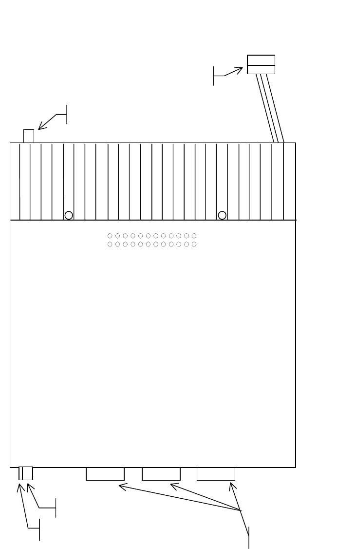
2.1 Front & Rear Panels
The front panel includes:
• One mini-UHF type female antenna
connector for the auxiliary receiver
• One SMA type female connector for the
GPS receiver
• Two LED indicators
• Three DE-9F RS232 ports
The rear panel includes:
• One mini-UHF type female antenna
connector for the main transceiver
• One 3-pin pigtailed power connector
with ignition sense

120 20110-003 PRELIMINARY Gemini/PD Technical Manual
3
2.1.1 LED Indicators
The Gemini/PD has two LED indicators:
LED’s
name Indicates Description
PWR red DC Power is applied
red Unit transmit
RX/TX green Unit receive
flashing
red/green Radio is unlocked
2.2 DTE Port Interface
For all three ports:
DE-9 F
pin # Function
1 DCD – from Gemini/PD, normally
asserted
2 RXD – data from Gemini/PD
3 TXD – data to Gemini/PD
4 DTR – to Gemini/PD, handshaking
5 Ground
6 DSR – from Gemini/PD, tied to
VCC through current limiting resis-
tor
7 RTS - to Gemini/PD, handshaking
8 CTS – from Gemini/PD, hand-
shaking
9 AUX auxiliary input to Gemini/PD,
“panic line” input (port 3):
It may be activated by dry contact
pull-up to the port’s DSR output. It
may also tolerate user pull-up to
external +12 VDC (car battery), but
an isolated dry contact is preferred
due to the risk of noise related false
alarms caused by the vehicle’s
electrical system.
We recommend the use of a shielded 9-wire
cable with all pins connected. These ports
can be used for unit configuration, mainte-
nance & adjustment as well to connect user
applications.
2.2.1 RS-232 Interface Signal
Levels
In the descriptions of data signals, the fol-
lowing conventions are used:
Table 1 - RS-232 Signal Levels
Term Alternates Signal level
ON asserted, spacing +3 to +15 V
OFF dropped, marking -3 to -15 V
120 20110-003 PRELIMINARY Gemini/PD Technical Manual
4
3. Adjustments and
Maintenance
1.1 Overview
This chapter outlines the basic adjustment pro-
cedures required upon initial installation and
thereafter at prescribed maintenance intervals.
Units are delivered from the factory properly
aligned and tested on the frequencies specified
at time of order. Adjustment beyond that de-
scribed in this chapter is not required unless ra-
dio modules have been tampered with or re-
paired. In such cases we recommend complete
factory re-alignment as special test jigs are re-
quired.
3.1 Intended Audience
This chapter is intended for use by installation
and maintenance personnel.
3.2 Equipment Required
The adjustments described below require the
following equipment:
• 13.6 VDC (nominal), 20A regulated power
supply.
• Radio service monitor (IFR or equivalent).
• Cable with mini-UHF male connector to
connect Gemini/PD to the service monitor.
• Gemini Radio Service Software,
• A 486 PC (or better) to run the RSS.
• Normal radio shop tools.
3.3 Maintenance Intervals
The adjustments described below should be
done at annual intervals or whenever a deterio-
ration in performance indicates that adjustment
may be required.
3.4 Tests & Adjustments
3.4.1 Preliminary Verification
Before performing any adjustment, verify the per-
formance of the unit as shown in the Table 1.
Important note: Before proceeding make sure that
the service monitor has been calibrated recently and
has warmed up for at least the time specified by its
manufacturer.
Some reported frequency and deviation problems
have actually been erroneous indications from serv-
ice monitors that have not adequately warmed up.
This is particularly likely when field service is done
during winter months.
3.4.2 Basic Tests & adjustments
Recommended Tests:
1. TX power output
2. Carrier frequency error
3. Frequency deviation
Note: Only if a loss in system performance has
been detected, RX SINAD and RX audio
distortion should be verified.
Adjustments:
1. Transmitter power output
2. Frequency error
3. Transmitter deviation
3.4.3 Tests & adjustments Proce-
dure
Refer to the RSS help file for details &
parameter information.
1. Connect the Gemini/PD main antenna con-
nector (or the auxiliary receiver) to the
TX/RX input of the service monitor using a
suitable length of 50 ohm cable.
2. Connect the Gemini/PD to a suitable power
supply and adjust the supply voltage to 13.6
volts.
3. Using a suitable 9 conductor straight RS-
232 cable, connect the Gemini port 1 to the
RS-232 port of a PC and run the Gemini
RSS program.
4. Press GET to get the configuration of the
unit.
5. Refer to “Tests and Adjustments” table.

120 20110-003 PRELIMINARY Gemini/PD Technical Manual
5
Table 1: Tests and Adjustments Full & Half ChannelUnits
STEP ACTION EXPECTED
RESULTS at
25°
°°
°C
MEASURE
WITH IF NOT?
1Output Power
Press PTT Channel x
40 watts 1
+10%, -20%
Service monitor
set to read power Check the RSS maximum power
output setting: must be set to 255
(means 40W). User can however
reduced it down to 10 Watts.
Refer to factory tech support.
2Frequency Error
Press PTT Channel x
±300 Hz Service monitor
set to read fre-
quency error
Adjust using the RSS Freq Warp
setting (fine tuning adjust)
(Typical adjust range is ±1.5KHz)
If found outside limits, user is
to call factory technical sup-
port.
3Deviation
Press PTT Channel x
Carrier will be modulated
with a 1 KHz tone.
For any bit rate
speeds selected:
Full channel unit
±4.0 kHz
+5%, -10%
Half channel unit
±2.5 kHz
+5%, -10%
Service monitor
set to read
deviation
Using RSS, adjust TX deviation.
4 Set the service monitor to generate a –80 dBm signal on the selected receive frequency. The signal should
be modulated with a 1.0 kHz tone. Open the top cover to access the radio (see 3.4.4)
To be performed only if a loss in system performance has been detected
512 dB SINAD
• For Full channel unit, set
deviation to ±3 kHz.
• For Half channel unit, set
deviation to ±1.5 KHz
• Set service monitor IF
filter to mid (15-30 kHz),
no audio filter.
Measure taken at
J400 pin 21 (RX1)
and at pin 23
(RX2)
≤ 0.5 µV 2
Service monitor
set for SINAD.
Connect to radio
connector J400
pin 21 (RX1) or
pin 23 (RX2).
Refer to factory technical support.
6Distortion
Use same settings as per 12
dB SINAD < 3%
Same as per
Step 5 Refer to factory technical support.
1 (unless you have set a lower value). Note that readings less than 40 watts may be due to losses in cables used for testing.
Check also your wattmeter frequency calibration curve. Do not be too ready to condemn the transmitter.
2 If a psophometrically weighted filter is available on the service monitor, use 0.35 µV.
120 20110-003 PRELIMINARY Gemini/PD Technical Manual
6
3.4.4 Opening the Unit
1. Remove the two Philips screw from the unit top cover.
2. Remove the top cover by lifting it from the rear.
3. Slide the cover out of the case.
24
23
2
1
J400
13.6Vdc Power connecto
r
Main Antenna co
n
necto
r
Aux. Receiver Antenna co
n
necto
r
GPS Receiver antenna connector
F
igure 1 Gemini/PD Top view (cover removed)
RS232 com ports
120 20110-003 PRELIMINARY Gemini/PD Technical Manual
7
3.4.5 GPS Diagnostics Procedure
OVERVIEW
The detection of the POSition message shows a GPS CONNECTED LED. After about three
minutes, detection of the one Pulse Per Second (PPS) should flash the POSITION ACQUIRED
indicator, this means that the GPS has a position solution.
If the GPS has a good view of the sky and still has not generated any position solution within
three minutes (it may take up to 10 minutes or more if the sky view is partially blocked.) the
following trouble-shooting procedures should be undertaken to isolate the fault:
1) Disconnect the GPS antenna cable connector from the Gemini radio and check for + 5 VDC
on the center pin of the GPS antenna connector on the radio using a DVM. If the voltage is
present, do not reconnect the cable and proceed to step 2.
2) With the DVM, measure resistance between the shell and the center conductor of the GPS ca-
ble, resistance should be between 100 and 300 Ohms, if it measures open or short circuit the
GPS antenna is either a passive antenna which is the WRONG type, or a defective active an-
tenna, replace with a known good active antenna.
3) Connect the new antenna to Gemini and wait about three minutes for the POSITION
ACQUIRED indicator to start flashing on Gemini, if not, the Gemini radio or its GPS receiver
is defective.

120 20110-003 PRELIMINARY Gemini/PD Technical Manual
8
4. Specifications
GENERAL
UHF 800 MHz
Frequency Tx 400 - 512 MHz1 806-824, (821-824)
Channel spacing 12.5, 20 or 25 kHz
Frequency Control Digital Synthesizer / uController
Frequency Stability 1.5 ppm
Operating temperature -30°C to +60°C (25°C nominal) @ 95% non-cond. RH
Modes of Operation Simplex or Half Duplex
Number of channels 16 internally stored
Supply voltage 13.6Vdc nominal (negative ground)
10.9 – 16.3 VDC
Circuit Protection 15 Amp fuse external
2 & 4 Amp fuse internal
RX Current at 13.6 VDC < 550 mA Standby (with auxiliary receiver)
TX Current at 13.6 VDC < 15 A
TX/RX separation 5 MHz typical
Nominal Dimensions 7.050” D x 6.000” W x 2.0000” H
Weight: < 3.5 lbs.
RF input/output Impedance 50 ohms nominal
RF connector Main TX/RX: mini-UHF female
Auxiliary RX: mini-UHF female
GPS RX: SMA female
Interface connector 3x DE-9F D-subminiature
RECEIVER
UHF 800
Frequency Rx 400-5121 MHz 851-869MHz (866-869)
Sensitivity (12 dB SINAD) < 0.35 µV *
Selectivity (25KHz) 75 dB typical
70 dB minimum
Selectivity (12.5) 65 dB typical
60 dB minimum
Intermodulation 75 dB typical
70 dB minimum
Spurious rejection 75 dB typical
70 dB minimum
FM hum & noise -45 dB typical *
Conducted spurious < -57 dBm
* psophometrically weighted filter
1 WARNING: The frequency band 406 to 406.1 MHz is reserved for use by distress beacons
and should not be programmed into the unit.

120 20110-003 PRELIMINARY Gemini/PD Technical Manual
9
TRANSMITTER
UHF
Power output 10-40 watts
Duty cycle 20% @ full power, 30 seconds maximum transmit time
Conducted Spurious -75 dBc (-38 dBm @10 W) typical
Frequency stability 1.5 ppm
FM hum and noise -45 dB max (25 kHz)
Attack time < 10 ms
MODEM OPERATION
Interface EIA RS-232C
Operation Simplex/half duplex
Data rates 4800 b/s 9600 b/s 19200 b/s
Modulation type DRCMSK DRCMSK DRCMSK
Packet Error Rate
(for < 1% error)
better than –110 dBm at 9600 b/s half channel
better than –115 dBm at 9600 b/s full channel
better than –112 dBm at 16000 b/s full channel
better than –109 dBm at 19200 b/s full channel
Protocol Dataradio Proprietary
DISPLAY and CONTROLS
2 status LEDs RX/TX, PWR
FCC / IC
CERTIFICATIONS
FCC IC (DOC)
UHF EOTGPDA 773195525A
800 MHz
900 MHz
120 10503-201 ii T-96S Technical Manual