CalAmp Wireless Networks RTU5 Remote Transmitter Unit RTU5 User Manual 4001 00XX SO RTU5 Operations Manual
LoJack Corporation Remote Transmitter Unit RTU5 4001 00XX SO RTU5 Operations Manual
UserManual.wiki
>
CalAmp Wireless Networks
>
RTU5 User Manual
Operations Manual
Navigation menu
Upload a User Manual
Namespaces
Wiki Guide
HTML
PDF
Info
Views
User Manual
Discussion / Help
Navigation
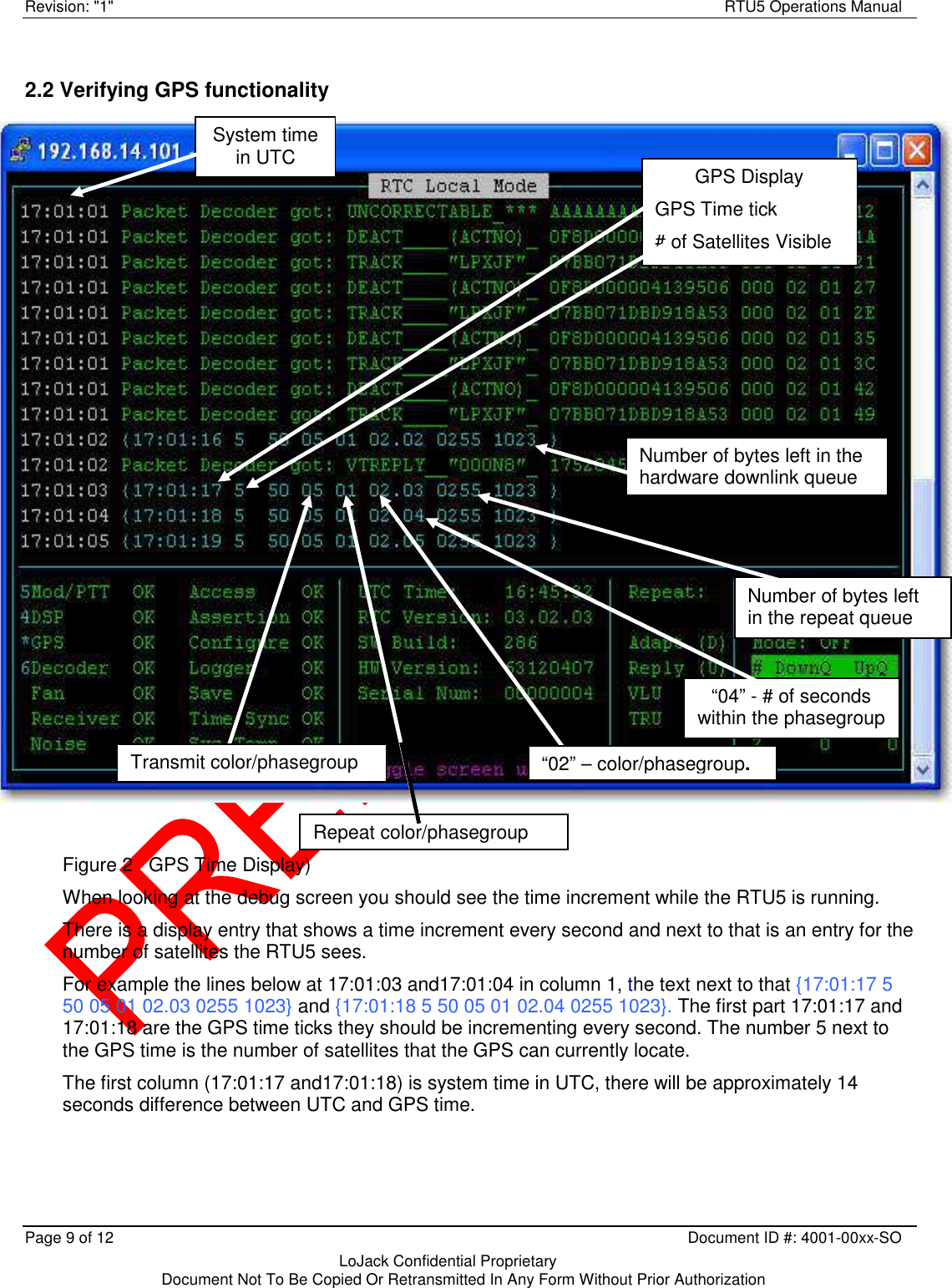
![RTU5 Operations Manual Revision: "1" Page 8 of 12 Document ID #: 4001-00xx-SO LoJack Confidential Proprietary Document Not To Be Copied Or Retransmitted In Any Form Without Prior Authorization 2.1 Main Screen components 2.1.1 Status Frame The status frame reports the status of the various aspects of the RTU5. 1. Mod/PTT – [OK|BAD] the status of the Mod/PTT channel. A BAD status indicates a problem communicating with the Mod/PTT. A BAD status here could indicate an incorrect MODPTT setting in the rtcconfig.cfg file. 2. DSP – [OK|BAD] the status of the DSP channel. A BAD status indicates a problem communicating with the DSP. A BAD status here could indicate an incorrect DSP setting in the rtcconfig.cfg file. 3. GPS – [OK|BAD|N/A] the status of the GPS signal. A BAD status indicates a problem communicating with the GPS. N/A will be displayed if no GPS is being used. The field will be prefixed with an “*” if the built in GPS is being used. 4. Decoder - [OK|BAD|N/A] the status of the Decoder signal. BAD Status indicates a problem communicating with the packet decoder. It will also indicate that a large number of garbled MSK formatted messages have been received, in this case the error will clear itself once a good packet has been received. 5. Fan - [OK|BAD] indicates the status of the RTU5 cooling fan. Referenced to the speed limits set in the config file. 6. Receiver - [OK|BAD] the status of the uplink receiver. A BAD status here could also indicate an incorrect UPLINK setting in the rtcconfig.cfg file. 7. Noise - [OK|BAD] BAD indicates an unacceptable noise level in the uplink receiver. 8. Access - [OK|BAD] BAD indicates a problem with permissions accessing various system resources such as the serial ports for the DSP, Decoder and Mod/PTT channels. 9. Assertion - [OK|BAD] BAD indicates that an internal software error has been detected. 10. Configure - [OK|BAD] BAD indicates a failure processing the configuration file. 11. Logger - [OK|BAD] BAD indicates a failure writing data to the condition logger. 12. Save - [OK|BAD] BAD indicates a failure to write configuration data to the rtcconfig.cfg file after a remote configuration has occurred. 13. TimeSynch - [OK|BAD] BAD indicates a TimeSynch (NTP) problem. Note that when time synchronization is lost the timing of transmissions will become randomized. 14. System Temp – [OK|BAD] indicates the internal temperature of the RTU5 in reference to the limits set in the config file.](https://usermanual.wiki/CalAmp-Wireless-Networks/RTU5/User-Guide-3400397-Page-8.png)