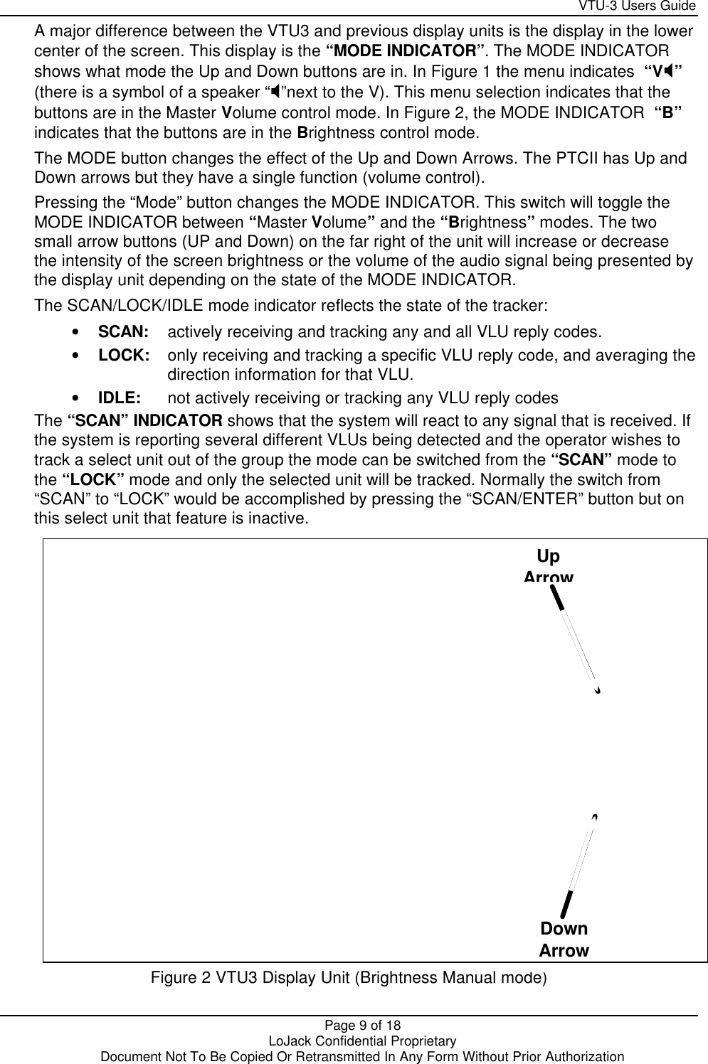
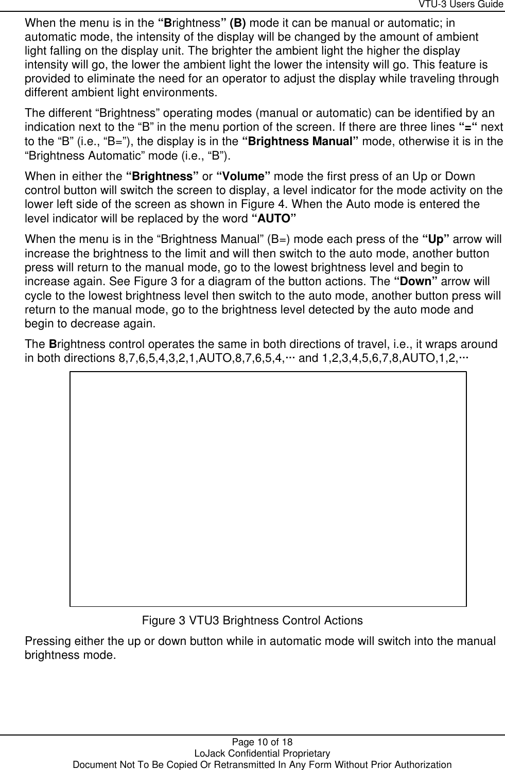
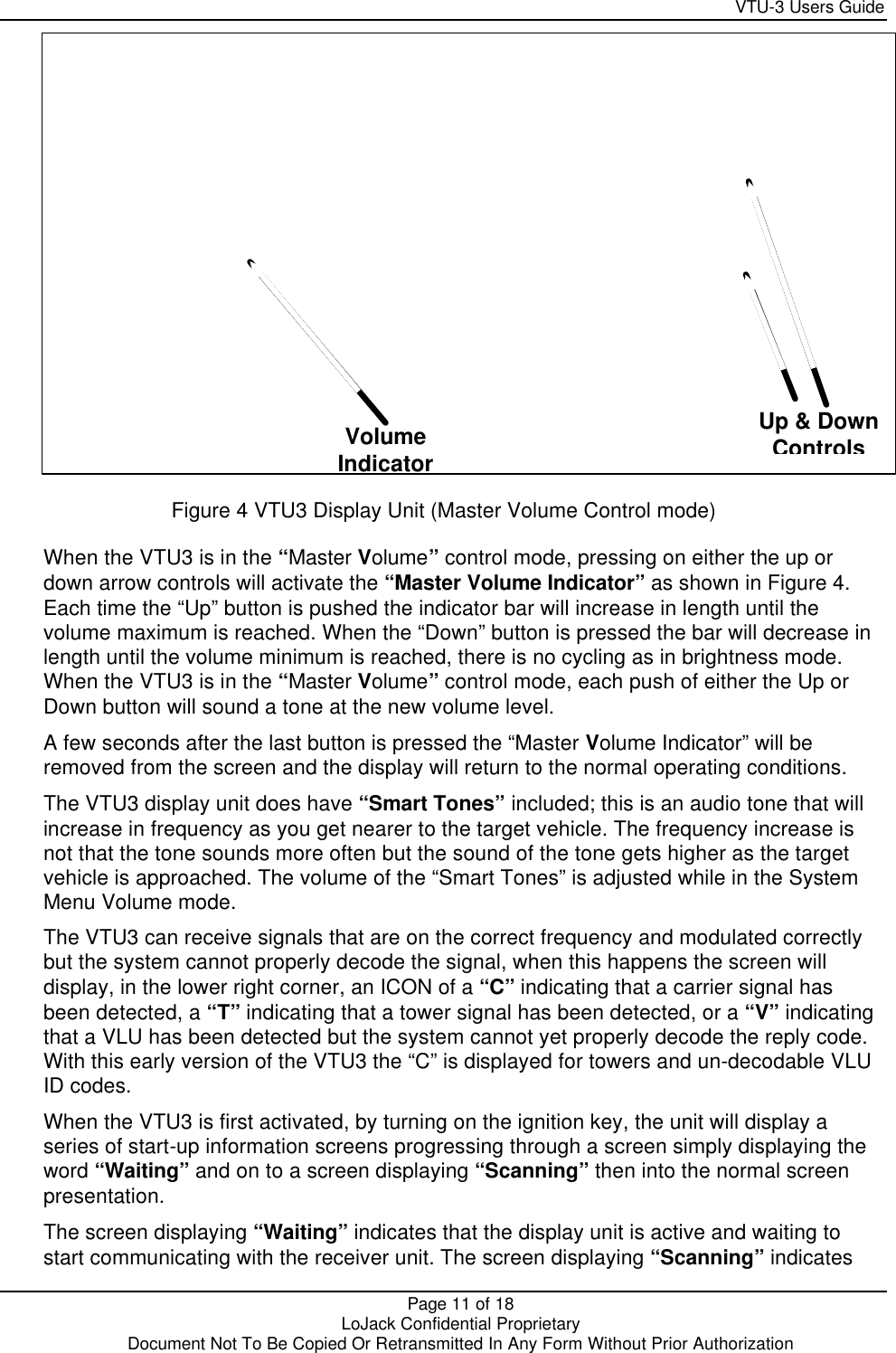
CalAmp Wireless Networks VTU3-US VTU3 Vehicle Tracking Unit User Manual VTU 3 Users Guide

LoJack Corporation VTU3 Vehicle Tracking Unit VTU 3 Users Guide

Users Manual

  LoJack Confidential Proprietary  Document Not To Be Copied Or Retransmitted In Any Form Without Prior Authorization       VTU-3 Users Guide      Author: Ed Gyte  Revision#: 0.1  Document ID: 4105-0001-UG  Document Name: VTU-3 Users Guide
    VTU-3 Users Guide  Page 2 of 18    LoJack Confidential Proprietary  Document Not To Be Copied Or Retransmitted In Any Form Without Prior Authorization  Copyright   Copyright  2004 by LoJack Corporation. All rights reserved. This document contains proprietary information protected by copyright.  This document is intended for use by LoJack internal customers and should be disclosed within the customer’s organization on a “need to know” basis.  This document shall not be reproduced by any means, stored on magnetic media, or made available directly or indirectly to any third party, without prior written consent of LoJack Corporation. Program listings may be entered, stored, and executed in a computer system, but may not be reproduced for publication.  The information in this document is subject to change without notice and should not be construed as a commitment by LoJack, which expressly disclaims any warranties, express or implied, including any implied warranty of merchantability or fitness for a particular purpose and assumes no liability for errors or omissions in this guide or any damages, direct or consequential resulting from its use.  All brand and/or product names are trademarks or registered trademarks of their respective holders.  Send Inquiries or comments to:  LoJack Corporation. 780 Dedham Street, Suite 700 Canton MA, 02021 USA Voice: 1-781 - 302 - 7100 Fax: 1-781 - 302 – 7299
    VTU-3 Users Guide  Page 3 of 18    LoJack Confidential Proprietary  Document Not To Be Copied Or Retransmitted In Any Form Without Prior Authorization   FCC Information  This equipment has been tested and found to comply with the limits for a Class A digital device, pursuant to part 15 of the FCC Rules. These limits are designed to provide reasonable protection against harmful interference when the equipment is operated in a commercial environment. This equipment generates, uses, and can radiate radio frequency energy and, if not installed and used in accordance with the instruction manual, may cause harmful interference to radio communications. Operation of this equipment in a residential area is likely to cause harmful interference in which case the user will be required to correct the interference at his own expense.
    VTU-3 Users Guide  Page 4 of 18    LoJack Confidential Proprietary  Document Not To Be Copied Or Retransmitted In Any Form Without Prior Authorization Document History  Version Status Date Author Description Approval                       0.1 Draft 01/28/2004  Original Development
    VTU-3 Users Guide  Page 5 of 18    LoJack Confidential Proprietary  Document Not To Be Copied Or Retransmitted In Any Form Without Prior Authorization Table Of Contents Section 1 About this Document...............................................................................................6 1.1 Purpose ...........................................................................................................................6 1.2 Organization ....................................................................................................................6 1.3 Typographical Conventions .............................................................................................7 Section 2 VTU-3 INTERFACE ...................................................................................................8 2.1 Background:...................................................................................................................12 2.2 Configuration: ................................................................................................................12 2.3 Installation:.....................................................................................................................12 2.4 Operation:......................................................................................................................12 2.5 Smart Audio:..................................................................................................................13 2.6 LCD Display:..................................................................................................................13   Table of Figures  Figure 1 VTU3 Display Unit ........................................................................................................8 Figure 2 VTU3 Display Unit (Brightness Manual mode) .............................................................9 Figure 3 VTU3 Brightness Control Actions...............................................................................10 Figure 4 VTU3 Display Unit (Master Volume Control mode).....................................................11
    VTU-3 Users Guide  Page 6 of 18    LoJack Confidential Proprietary  Document Not To Be Copied Or Retransmitted In Any Form Without Prior Authorization  Section 1 About this Document 1.1 Purpose This document is designed to explain the purpose, functionality and the operation of the latest innovations in the LoJack Stolen Vehicle Recovery System. 1.2 Organization This document is designed as a reference source.  It is not intended to replace or redefine current procedures. This document is broken down into the following major sections: Section 1: About this Document: This material explains the conventions that have been used in the development of this document, any formatting conventions or word usage conventions that need to be understood for full comprehension of the content of the document. Section 2:   VTU-3 Interface: This material explains the functional operation of the VTU-3, the display screen and the controls provided. Glossary: Defines various names and terms used by LoJack as a whole. All of the terms defined in this section may not appear in this document, but are provided in the event that they may be used in future communications concerning this material.
    VTU-3 Users Guide  Page 7 of 18    LoJack Confidential Proprietary  Document Not To Be Copied Or Retransmitted In Any Form Without Prior Authorization  1.3 Typographical Conventions Several type faces and text formats are used throughout this guide. Please refer to the following formatting in the text to help you identify special information.   Format: Type of Information Emphasis Words and characters in Times bold-italic type are used to emphasize the following: • Menu items • Screens names • Dialog boxes • References • Section titles • Heading titles • Names of reports • File names • Other manual titles  • Particular words  New Term Words and characters in Arial bold type are used to introduce a new term.  Type Command Words and characters in Century Schoolbook bold type indicate what you type on a command line from your keyboard.  Echo Words and characters in Century Schoolbook type indicate the result or output of a command or the contents of a file.
    VTU-3 Users Guide  Page 8 of 18    LoJack Confidential Proprietary  Document Not To Be Copied Or Retransmitted In Any Form Without Prior Authorization Section 2 VTU-3 INTERFACE As you can see in Figure 1 the VTU3 (PTCIII) is similar to the display units on previous tracking units (PTCI and PTCII).      Figure 1 VTU3 Display Unit On the left side of the unit is a screen that displays information about a Vehicle Locating Unit (VLU) installed in the target vehicle. On the right side of the unit is a group of buttons that are used to control the operation of the display unit. The characters on the upper left side of the screen display the “Reply Code” received from the VLU in the tracked vehicle.  One of the differences from the PTCI and PTCII is the fact that the VTU3 is capable of displaying an expanded number of characters. A sixth character is available for future use but is not active at this time. On the bottom left of the display screen is the “Signal Strength Indicator”. This indicator works the same as on previous units, as you get closer to the target vehicle the number of vertical bars will increase. On the right side of the display screen is the “Direction Indicator” (Relative Bearing Indicator). This indicator is the same as on previous units, it displays the direction of travel required to intercept the target vehicle. In the group of buttons on the display unit there is a button labeled “SCAN/ENTER”, this button is not active at this time. Reply Code Direction Indicator Mode Button Up Arrow Down Arrow Signal Strength Indicator Scan/Enter Button System Menu
    VTU-3 Users Guide  Page 9 of 18    LoJack Confidential Proprietary  Document Not To Be Copied Or Retransmitted In Any Form Without Prior Authorization A major difference between the VTU3 and previous display units is the display in the lower center of the screen. This display is the “MODE INDICATOR”. The MODE INDICATOR shows what mode the Up and Down buttons are in. In Figure 1 the menu indicates  “VX” (there is a symbol of a speaker “X”next to the V). This menu selection indicates that the buttons are in the Master Volume control mode. In Figure 2, the MODE INDICATOR  “B” indicates that the buttons are in the Brightness control mode. The MODE button changes the effect of the Up and Down Arrows. The PTCII has Up and Down arrows but they have a single function (volume control). Pressing the “Mode” button changes the MODE INDICATOR. This switch will toggle the MODE INDICATOR between “Master Volume” and the “Brightness” modes. The two small arrow buttons (UP and Down) on the far right of the unit will increase or decrease the intensity of the screen brightness or the volume of the audio signal being presented by the display unit depending on the state of the MODE INDICATOR. The SCAN/LOCK/IDLE mode indicator reflects the state of the tracker: • SCAN: actively receiving and tracking any and all VLU reply codes. • LOCK: only receiving and tracking a specific VLU reply code, and averaging the direction information for that VLU. • IDLE: not actively receiving or tracking any VLU reply codes The “SCAN” INDICATOR shows that the system will react to any signal that is received. If the system is reporting several different VLUs being detected and the operator wishes to track a select unit out of the group the mode can be switched from the “SCAN” mode to the “LOCK” mode and only the selected unit will be tracked. Normally the switch from “SCAN” to “LOCK” would be accomplished by pressing the “SCAN/ENTER” button but on this select unit that feature is inactive.   Figure 2 VTU3 Display Unit (Brightness Manual mode)  Up Arrow Down Arrow
    VTU-3 Users Guide  Page 10 of 18    LoJack Confidential Proprietary  Document Not To Be Copied Or Retransmitted In Any Form Without Prior Authorization When the menu is in the “Brightness” (B) mode it can be manual or automatic; in automatic mode, the intensity of the display will be changed by the amount of ambient light falling on the display unit. The brighter the ambient light the higher the display intensity will go, the lower the ambient light the lower the intensity will go. This feature is provided to eliminate the need for an operator to adjust the display while traveling through different ambient light environments. The different “Brightness” operating modes (manual or automatic) can be identified by an indication next to the “B” in the menu portion of the screen. If there are three lines “=“ next to the “B” (i.e., “B=”), the display is in the “Brightness Manual” mode, otherwise it is in the “Brightness Automatic” mode (i.e., “B”). When in either the “Brightness” or “Volume” mode the first press of an Up or Down control button will switch the screen to display, a level indicator for the mode activity on the lower left side of the screen as shown in Figure 4. When the Auto mode is entered the level indicator will be replaced by the word “AUTO” When the menu is in the “Brightness Manual” (B=) mode each press of the “Up” arrow will increase the brightness to the limit and will then switch to the auto mode, another button press will return to the manual mode, go to the lowest brightness level and begin to increase again. See Figure 3 for a diagram of the button actions. The “Down” arrow will cycle to the lowest brightness level then switch to the auto mode, another button press will return to the manual mode, go to the brightness level detected by the auto mode and begin to decrease again.  The Brightness control operates the same in both directions of travel, i.e., it wraps around in both directions 8,7,6,5,4,3,2,1,AUTO,8,7,6,5,4,··· and 1,2,3,4,5,6,7,8,AUTO,1,2,···  Figure 3 VTU3 Brightness Control Actions Pressing either the up or down button while in automatic mode will switch into the manual brightness mode.
    VTU-3 Users Guide  Page 11 of 18    LoJack Confidential Proprietary  Document Not To Be Copied Or Retransmitted In Any Form Without Prior Authorization    Figure 4 VTU3 Display Unit (Master Volume Control mode) When the VTU3 is in the “Master Volume” control mode, pressing on either the up or down arrow controls will activate the “Master Volume Indicator” as shown in Figure 4. Each time the “Up” button is pushed the indicator bar will increase in length until the volume maximum is reached. When the “Down” button is pressed the bar will decrease in length until the volume minimum is reached, there is no cycling as in brightness mode.  When the VTU3 is in the “Master Volume” control mode, each push of either the Up or Down button will sound a tone at the new volume level. A few seconds after the last button is pressed the “Master Volume Indicator” will be removed from the screen and the display will return to the normal operating conditions. The VTU3 display unit does have “Smart Tones” included; this is an audio tone that will increase in frequency as you get nearer to the target vehicle. The frequency increase is not that the tone sounds more often but the sound of the tone gets higher as the target vehicle is approached. The volume of the “Smart Tones” is adjusted while in the System Menu Volume mode. The VTU3 can receive signals that are on the correct frequency and modulated correctly but the system cannot properly decode the signal, when this happens the screen will display, in the lower right corner, an ICON of a “C” indicating that a carrier signal has been detected, a “T” indicating that a tower signal has been detected, or a “V” indicating that a VLU has been detected but the system cannot yet properly decode the reply code. With this early version of the VTU3 the “C” is displayed for towers and un-decodable VLU ID codes. When the VTU3 is first activated, by turning on the ignition key, the unit will display a series of start-up information screens progressing through a screen simply displaying the word “Waiting” and on to a screen displaying “Scanning” then into the normal screen presentation. The screen displaying “Waiting” indicates that the display unit is active and waiting to start communicating with the receiver unit. The screen displaying “Scanning” indicates Volume Indicator Up & Down Controls
    VTU-3 Users Guide  Page 12 of 18    LoJack Confidential Proprietary  Document Not To Be Copied Or Retransmitted In Any Form Without Prior Authorization that the display and the receiver unit are communicating. After the word “Scanning” appears on the screen the different ICONs can start to be displayed indicating that the system is communicating and receiving signals from different sources. 2.1 Background: VTU-3 is an extensive redesign of the LoJack Police Tracking Computer (PTCII) used for stolen vehicle recovery.  The redesign effort was initiated for several reasons as follows: • Enhanced performance would be incorporated into a redesign  • Easier operation would be achieved with a redesign  • New features would be incorporated into a redesign. Configuration: 2.2 Configuration: VTU-3 consists of an antenna array, an electronics chassis, a control and display head, and cabling between these components. 2.3 Installation: • Installation of the antenna array is by drilling 4 holes (3/4" diameter) into the roof of a tracking vehicle.  The holes are in a square pattern in the middle of the roof or away from other equipment such as other antennas or light bars. • Installation of the VTU-3 electronics chassis is by mounting the chassis in the trunk or rear storage (boot) of the vehicle. • The cabling between the antenna array and the electronics chassis is between the roof liner and the roof, into the trunk and the cables plug into the electronics chassis. • Power wiring (+12V and ground) is on a separate connector on the electronics chassis. • Installation of the VTU-3 Control and Display head is on the dashboard or attached to the roof over the rear view mirror. A mounting bracket is provided. • The data cable is connected between the electronics chassis and the Control and Display head.  The connectors are RJ-11 (phone) type. 2.4 Operation: Overall operation with regard to front panel controls is very simple.  This can be seen from the fact that there are few controls on the front panel. Power-on self-test is performed automatically.  The test takes only about 1-2 seconds and then the unit displays READY for an additional second. The only control necessary is the volume control.  The volume is adjusted via up/down buttons.  An audio tone is presented during adjustment. The SCAN button is only used when a second VLU is present.  The unit automatically sets the SCAN mode correctly during normal operation.
    VTU-3 Users Guide  Page 13 of 18    LoJack Confidential Proprietary  Document Not To Be Copied Or Retransmitted In Any Form Without Prior Authorization 2.5 Smart Audio: 'Smart Audio' has been included in VTU-3 and is incorporated in several ways.  First, as previously explained, the volume control reports back as “V” is adjusted.  Next, when a 'Stolen LoJack' is decoded, at any signal strength, a clean beep will be presented.  This is because the electronics handles-all the decisions regarding squelch and noise and interpretation of the LoJack signal.  Tower signals, and other interference, will be ignored.  When the electronics determines that the beep should be presented, it synthesizes the audio for clarity.  The electronics is expected to be as good, or better than a human ear in listening for a LoJack signal. Next, the first time a reply code is decoded, the audio beep will be fairly loud.  This is to get the operators attention in case the operator has turned the volume down very low.  After the first beep, the volume will be at the level set by the operator. Next, the audio beep will change tone (not volume) in proportion to the signal strength display.  As the signal strength increases, the tone increases.  This should result in tracking without constantly watching the display. Next, a different tone will be presented when the signal strength becomes full scale.  This will alert the operator to start visual tracking (this is in case the operator is not watching the display and would not otherwise know that full scale has been reached).  Finally, when tracking an LJU, and another LJU is present, a second, distinctive tone is presented.  The operator may then use the SCAN button to select between the two VLU units.  2.6 LCD Display: A Liquid Crystal Display (LCD). A sun shield is not included since the display is more visible and easier to read in daylight, even in direct sunlight. A backlight will appear for nighttime viewing whenever there is a display on the screen.  The Reply Code alphabet is constructed from 19 segment characters. The Signal Strength display is one continuous row of 25 segments.  A row of small reference dots is presented when any signal strength is displayed.  This shows the relative scale of the displayed signal strength bars. A single rotating arrow presents the direction information.
    VTU-3 Users Guide  Page 14 of 18    LoJack Confidential Proprietary  Document Not To Be Copied Or Retransmitted In Any Form Without Prior Authorization Glossary Acronyms: A   Ack Acknowledgement AES (Tower to Tower Communications – International term) AJD Anti Jam Disable B  Base Ack Acknowledgement by TRTU BBU Battery Back-up Unit BOM Bill Of Material C  CP Command Post D  DSP Digital Signal Processor E  ETSI European Telecommunications Standards Institute F  FCC Federal Communications Commission FSK Frequency Shift Keying G  GPRS General Packet Radio Service GPS Global Positioning System GSM  Global System for Mobile Communications I  IA Instant Activation ITU Installation Test Unit L  LCIMS LoJack Corporate Information Management System. LJU LoJack Unit (See VLU. This abbreviation is used primarily in the USA.) LJU3 LoJack Unit.  Also known as VLU3.  LP Listening Post LPRT Listening Post / Remote Transmitter M  MOD/PTT Modulator/ Push To Talk MSK Minimum Shift Keying MSM Motion Sensing Module MTBF Mean Time Between Failure N  NAK Not Acknowledged NTP Network Time Protocol P  PCB Printed Circuit Board PDA Personal Digital Assistant PDT Portable Data Terminal PSU Power Supply Unit PURR Periodic Uplink Response Rate
    VTU-3 Users Guide  Page 15 of 18    LoJack Confidential Proprietary  Document Not To Be Copied Or Retransmitted In Any Form Without Prior Authorization Q   QA Quality Assurance R  RAS Registration and Activation System RLU3 Ruggedized VLU3 RMS ADC ????? RT Remote Transmitter RTC Remote Transmitting Computer (term obsolete See RTU) RTU Remote Transmission Unit, collective term for a site RTU Lite Repeater with intelligence S  SAC Sector Activation Computer SNDECODE Secret Number Decoder application SNMP Simple Network Management Protocol T  TBC To Be Confirmed. TBD To Be Defined. TDM Time Division Multiplexing TR Switch Transmit/Receive Switch TTU ????? U  Unit Ack ????? V   VAC Vehicle Activation Computer (International term) VAT Vehicle Activation Transmitter VLU Vehicle Locating Unit. VTC Vehicle Tracking Computer (Obsolete term See VTU) VTR Vehicle Tracker (most common) VTU Vehicle Tracking Unit
    VTU-3 Users Guide  Page 16 of 18    LoJack Confidential Proprietary  Document Not To Be Copied Or Retransmitted In Any Form Without Prior Authorization Definitions Activation Code .. The code associated with a LoJack Unit that is used for activating or deactivating the unit. Adaptive configuration A supported configuration in which the VLU-5N will synchronize to a TRTU, and operate its receiver with a duty cycle in order to reduce average current consumption.  When an Adaptive unit is out of range of a TRTU or TRU, it will operate its receiver continuously, hence drawing more current than when synchronized. AES Intellinet A manufacturer of security and wireless communication products in the USA Alert ID Character string transmitted by a Vehicle Locating Unit triggered by a motion sensor (MSM) Alpha Paging Alpha Paging is a text message sent to a pager.  These messages may include alphabetic and numeric characters.  Antenna Tuning Unit (ATU) A circuit that can be adjusted to minimize the mismatch between the antenna and the unit's transmit and receive circuits. Arm Code  Backup Battery A 6.0V battery that can be connected to the Adaptive, Full Service, or Low Current VLU-5N to provide backup and transmit power, if and when the primary battery is removed or discharged.  The backup battery is replaced with a transmitter battery in the Portable model. Box Number The Vehicle Locating Unit Serial number Central System ... Incorporates the Transmission System and the Registration and Activation System Configuration ID . Deactivation ID.... Alternate character string for deactivating a Vehicle Locating Unit Dedicated Battery A 3.6V battery that supplies power to the VLU-5N processor and receiver circuits in the Portable configuration. Domestic VLU or Wideband VLU...............  A unit that is designed and manufactured to FCC requirements.   This includes any unit that is not ETSI compatible, including units shipped to non-ETSI countries.  Domestic TRTU units are configured to work with the standard LoJack 8 seconds TRTU system and has a 25 KHz bandwidth.  See TRTU below.  The domestic VLUX is specified in a separate document.  See Reference 14.  LoJack IV Vehicle Transceiver Version R02.02 DRAFT Downlink Minimum Shift Keying transmission from Remote Transmission Unit to Vehicle Locating Unit DSP Card Digital Signal Processor Card (part of the Uplink Receiver assembly) Early Warning  Early Warning Detector (EWD) See Motion Sensing Module (MSM) ETSI A unit that is designed and manufactured to European Telecommunication Standards Institute requirements. Extended Message A message generally sent from the TRTU system to the VLU-5N unit.  Extended messages are not part of the original LoJack standard messages.  They extend the number of messages in the system to increase versatility Full Service Configuration (FS) ...............A model that will not attempt to synchronize with a TRTU system. Installation and Test Unit (ITU)................A special purpose test instrument that allows testing of a VLU-5N.   The ITU communicates to the VLU-5N using the TEST REQUEST command according to the VLU-5N protocol. LE Liaison. Law Enforcement Liaison is a LoJack employee with responsibility of interfacing with law enforcement agencies.
    VTU-3 Users Guide  Page 17 of 18    LoJack Confidential Proprietary  Document Not To Be Copied Or Retransmitted In Any Form Without Prior Authorization LoJack Timed Remote Transmitter Unit (LoJack TRTU)........Synchronous LoJack TRTUs that incorporate  precise timing control, facilitating the use of time-windowed synchronization of VLUs.  The TRTU system uses different timing than the LoJack system LoJack Unit (LJU)A LoJack vehicle mounted module, which can be activated by a compatible system and tracked by a tracking receiver.  Also referred to as Vehicle Transceivers (VTs) or Vehicle Location Units (VLUs). Low Current configuration (LC)........A low current model, configured during manufacture, powered by 12V.   A VLU-5N in this configuration will maintain a low lifetime average current even when not synchronized to a TRTU system. LPRT LPRT (Listening Post/Remote Transmitter) is the tower site computer.  This is the equivalent of the RTU (Remote Transmission Unit) upgraded with additional functionality. Motion Sensing Module (MS)....... An electronic module that can sense the presence of vehicle motion, and  issue a "Movement Alert" message via the VLU-5N's Motion Sensor Interface.  Also may be described as an Early Warning Detector (EWD) Motion Sensor Interface (MSI) The interface pins on the VLU-5N that connect to the Motion Sensor Module.   If both pins are pulled high by the MSM, the VLU-5N will register a motion event and act accordingly. Non-Timed Remote Transmitter Controller (Non-TRTU)..An RTU system that does not adhere to the strict  timing requirements of the synchronous TRTU system (see Timed TRTU). Output  Packet Decoder... An Minimum Shift Keying transponder that decodes Reply Codes; and can act as a Repeater Periodic Uplink Response Rate.........Certain Uplink messages are sent by the VLU-5N at a Periodic Uplink  Response Rate.  These messages are sent n times at intervals of in minutes then x times at intervals of y minutes (where n, in, x, and y are configurable parameters).  The broadcast of the message will continue until the unit sends n and x messages OR it receives an appropriate BASE ACK.  The reception of the appropriate BASE ACK indicates that the message has been received by the system and transmissions can cease.  The rates (n, in, x, and y) are global parameters and all messages that use the Periodic Uplink Response Rate use the same values (in a particular VLU-5N).  "Out of ITU" message uses just the x and y values. Portable Configuration A very low current model, configured during manufacture, powered by a dedicated battery and a transmitter battery used only to power the transmitter.  The Portable configuration will maintain a very low lifetime average current even when not synchronized to a TRTU system. Portable RTU Remote Transmission Unit designed to be easily moved Primary Power .... Primary power is used with the Adaptive, Full Service, and Low Current models to denote vehicle power.  Primary power in the Portable configuration is supplied by the 3.6 V dedicated battery. Remote Transmitter Unit (RTU) .......... Part of the system infrastructure which receives commands from the  system central computer via phone lines or other communication techniques and broadcasts packets to VLU-5Ns over the RF channel according to the RF Communications Specification.   Repeater Tracker Repeater Unit (TRU is obsolete) Reply Code The code associated with a LoJack Unit that is used to speed-up a unit.  The reply code is transmitted from a LoJack Unit when it is activated.  The reply code is received by Police Trackers. RF Amplifier Manufacturer of UK RF Amps SAC A Sector Activation Computer is a LoJack Computer that calls the Listening Post/Remote Transmitter’s for LoJack Unit Activations, Speed-ups (Tracks), and Deactivations, based on commands from a Law Enforcement Computer.
    VTU-3 Users Guide  Page 18 of 18    LoJack Confidential Proprietary  Document Not To Be Copied Or Retransmitted In Any Form Without Prior Authorization Standard Message A message generally sent from the TRTU system to the VLUX unit.  Standard messages conform to the original LoJack message format Timed Remote Transmitter Unit (TRTU)..........  Refers to a system of synchronous RTUs which incorporate  precise timing control, facilitating the use of time-windowed synchronization of VLU-5Ns.  The LoJack TRTU system and the TRTU systems use different timing. TRACKER Network Unit (TNU) A name for a TRACKER version of a VLU-5N. TRACKER Repeater Unit (TRU)...A specially configured TRACKER "MK 2" unit that relays TRTU messages  downstream and Uplink messages upstream.  TRUs can be daisy chained such that a TRU feeds another TRU.  Used to fill in areas of coverage and relay reply codes from activated units. Transmitter Battery A 6V battery that provides power solely to the transmitter circuits in a portable VLU-5N.  This battery uses the same input connection as the Backup Battery on the Adaptive Model. Transmission System Communications subsystem that interfaces to Remote Transmission Units Transponder Category of RF equipment that the Vehicle Locating Unit belongs in. Unit ID  Uplink Frequency Shift Keying transmission from Vehicle Locating Unit to Remote Transmission Units Uplink An infrastructure enhancement that allows VLUs to send appropriately formatted messages directly to the TRTU system.  The Uplink operates on the same basic frequency as the rest of the system infrastructure.  The Uplink channel uses a much slower data rate to help make up for the reduced signal margin of the VLU transmit power relative to that of TRTU towers. Uplink Central .....  Uplink Receiver... Receiver Analogue Unit designed for decoding Uplink (Frequency Shift Keying) messages transmitted by Vehicle Locating Unit s VB VOICE VB VOICE is a Visual Basic programming module, including a hardware board, which performs automated calling of phone numbers with voice messages.   Vehicle Transceiver (VT, VLU, or VLC).A vehicle mounted module, which can be activated by a compatible  system and tracked by a tracking receiver.  Also referred to as Vehicle Location Units (VLUs), or Vehicle Location Communicators (VLCs). Vehicle power The +12V vehicle electrical system supplies power to the VLU-5N in either TRTU or non-TRTU configurations, except in portable units. Vehicle Tracking Receiver or Units (VTR or PTC) ....Provides the ability to track an activated VLU-5N, and  allows the vehicle location to be determined.  Usually mounted on police vehicles and are often referred to as Police Tracking Computers (PTCs). VLU Vehicle Locating Unit. A transponder hidden in the vehicles that can be remotely activated. The transmission from Vehicle Locating Unit can be decoded by Vehicle Tracking Unit. VTU Vehicle Tracking Unit. A direction-finding receiver used by the tracking agency in a mobile environment. (Used to be called PTC.)

Navigation menu