CalAmp 3640LAB Vehicle tracking and telemetry device with vehicle bus interface and Bluetooth connectiviy User Manual
CalAmp Vehicle tracking and telemetry device with vehicle bus interface and Bluetooth connectiviy
CalAmp >
User Manual
9/27/2017 LMU-3640 Hardware & Installation Guide - PULS Wiki
https://puls.calamp.com/wiki/LMU-3640_Hardware_%26_Installation_Guide 1/23
LMU-3640 Hardware & Installation Guide
LMU-3640™
Hardware and Installation Guide
IMPORTANT: DO NOT INSTALL OR USE THE SOFTWARE
OR DOCUMENTATION UNTIL YOU HAVE READ AND
AGREED TO THE LICENSE AGREEMENT AND REVIEWED
THE LIMITED WARRANTY AND REGULATORY
INFORMATION.
1 Introduction
Welcome to the LMU-3640™ Hardware and Installation Guide. This
manual is intended to give you information on the basic setup and
installation of the CalAmp LMU-3640™ product(s) including
hardware descriptions, environmental specifications, wireless network
overviews and device installation.
1.1 About This Manual
The LMU-3640™ is one of the most flexible economy mobile
tracking hardware products available. In order to accurately
describe the functionality of these units we have broken this
manual into the following sections:
System Overview – A basic description of a
CalAmp LMU-3640™ based tracking system. This
includes a description of roles and responsibilities
of each of the CalAmp components as well as a
brief overview of the wireless data technologies
used by the LMU-3640™.
Hardware Overview – Describes the physical
characteristics and interfaces of the LMU-3640™.
Installation and Verification – Provides guidance
for the installation of the LMU-3640™ versions in a
vehicle and instructions on how to verify the
installation is performing adequately.
1.2 About The Reader
Contents
1 Introduction
1.1 About This Manual
1.2 About The Reader
1.3 About CalAmp
1.4 About the CalAmp Location Messaging Unit - LMU-3640™
2 System Overview
2.1 Overview
2.2 Component Descriptions
2.2.1 Backend Software
2.2.2 LMU Manager
2.2.3 LM Direct Server
2.2.4 Wireless Data Network
2.2.5 LMU-3640™
2.2.6 Host Device – Laptop/PDA or MDT
2.3 Wireless Data Primer
2.3.1 SMS (Short Message Service)
3 Hardware Overview
3.1 LMU-3640™
3.1.1 Environmental Specifications
3.1.2 Physical Specifications
3.2 Location Messaging Unit - LMU-3640™
3.3 LMU-3640™ Connectors
3.3.1 I/O Connector
3.3.2 VBUS Connector
3.3.3 Accessories
3.4 GPS Receiver
3.5 I/O Descriptions
3.5.1 3-Axis Accelerometer Input
3.5.2 Ignition and Inputs
3.5.3 Outputs
3.5.4 Status LEDs
4 Configuration and Activation
4.1 Quick Start - General Config
4.2 Activating LTE Using AT Commands
4.3 Auto provisioning of GSM or HSPA LMUs
4.4 Activating GSM or HSPA LMU using AT Commands
4.5 Preparing for Installation
4.6 Plan The Installation
4.6.1 Size and Placement of LMU Unit
4.6.2 Access to the SIM (Subscriber Identity Module) Card
4.6.3 Protection from Heat
4.6.4 Visibility of Diagnostic LEDs
4.6.5 Cable Length
4.6.6 Moisture and Weather Protection
4.6.7 Preventing Accidental or Unauthorized Modification
4.7 Installing the LMU in a Vehicle
4.7.1 Place the LMU unit in the vehicle.
4.7.2 Connect power, ignition, and ground.
4.7.3 Typical Connection Sequence
4.8 Installation Verification
4.8.1 Comm Verification
4.8.2 GPS Verification
4.8.3 Inbound Verification
4.8.4 Verification via SMS
In order to limit the size and scope of this manual, the following assumptions have been made about the reader.
1. You are familiar with GPS concepts and terminology

9/27/2017 LMU-3640 Hardware & Installation Guide - PULS Wiki
https://puls.calamp.com/wiki/LMU-3640_Hardware_%26_Installation_Guide 2/23
2. You have some experience with installing equipment in vehicles
3. You are familiar with the use of AT Commands
4. You are familiar with the use of terminal programs such as HyperTerminal or PuTTY
1.3 About CalAmp
CalAmp is a leading provider of wireless communications products that enable anytime/anywhere access to critical information, data and
entertainment content. With comprehensive capabilities ranging from product design and development through volume production, CalAmp
delivers cost-effective high quality solutions to a broad array of customers and end markets. CalAmp is the leading supplier of Direct Broadcast
Satellite (DBS) outdoor customer premise equipment to the U.S. satellite television market. The Company also provides wireless data
communication solutions for the telemetry and asset tracking markets, private wireless networks, public safety communications and critical
infrastructure and process control applications. For additional information, please visit the Company’s website at www.calamp.com
(http://www.calamp.com/) .
1.4 About the CalAmp Location Messaging Unit - LMU-3640™
The CalAmp Location and Messaging unit-LMU-3640™ is a mobile device that resides in private, commercial or government vehicles. The
LMU-3640™ is a single box enclosure incorporating a processor, a GPS receiver, a wireless data modem, and a vehicle-rated power supply. The
LMU-3640™ also supports inputs and outputs to monitor and react to the vehicular environment and/or driver actions..
The LMU-3640™ collects, stores and transmits vehicular and location data over a designated wireless network including LTE and HSPA.
Vehicular and location data are transmitted to a customized software application that has been designed to receive, acknowledge, process, store,
and respond to this data.
Unit location and vehicular information is sent at pre-determined intervals, on demand, or when pre-programmed vehicular conditions are met.
Transmission of data are sent immediately when in wireless network coverage and stored for later transmission when out of the wireless coverage
area. SMS messaging can be used as an alternative or redundant communication backup.
The LMU-3640™ is designed to support a variety of custom fleet applications starting with basic automatic vehicle location and including
applications requiring more sophisticated features such as geo-fencing, speed and mileage monitoring, third party security monitoring, dynamic
reporting routines, and an array of exception alerts.
LMU-3640™ are sold exclusively to authorized systems integrators, software firms, and service providers who have developed their offering
around the capabilities of the LMU-3640™. Customers are trained by CalAmp to integrate the mobile device with their system and to assist in
support and maintenance of the devices.
Installations of LMU-3640™ are performed by CalAmp customers or contracted installers. Typical installations include hook-up to power,
ignition, and ground. LMU-3640™s and the corresponding wiring are almost always hidden from view and general access. Placement of the units
is usually under dashboards, in trunks or in compartments.
2 System Overview
2.1 Overview
The entire purpose behind a fleet management system is to be able to remotely contact a vehicle, determine its location or status, and do
something meaningful with that information. This could include displaying the vehicle location on a map, performing an address look-up,
providing real-time driving directions, updating the vehicles ETA, monitoring vehicle and driver status or dispatching the vehicle to its next pick
up.
These functions, of course, are completely dependent on the capabilities of the vehicle management application. The role of the CalAmp LMU-
3640™ is to deliver the location information when and where it is needed.
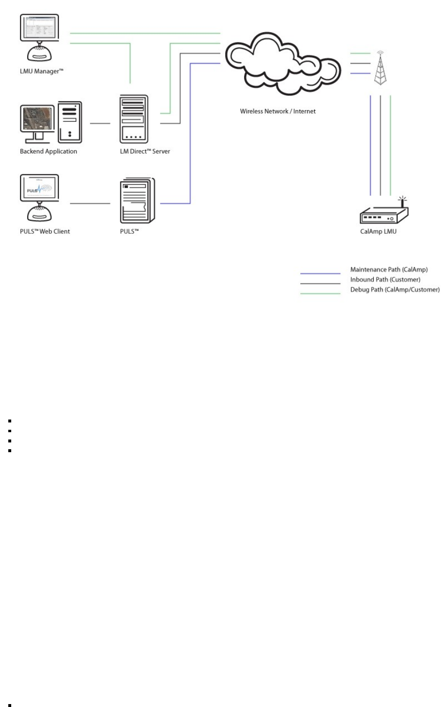
A typical fleet management system based on a CalAmp device includes the following components:
A wireless data network
An LMU-3640™
Host Device (GPS NMEA only)
An LM Direct™ communications server
Backend mapping and reporting software which typically includes mapping and fleet reporting functions
PULS™
LMU Manager™
9/27/2017 LMU-3640 Hardware & Installation Guide - PULS Wiki
https://puls.calamp.com/wiki/LMU-3640_Hardware_%26_Installation_Guide 3/23
2.2 Component Descriptions
2.2.1 Backend Software
Backend software is a customer provided software application. Regardless of its purpose one of its primary functions is to parse and present data
obtained from the LM Direct server. This allows the application to do any of the following:
Display location data base on reports received from the LMU-3640™ in a variety of formats.
Present historic information received from the LMU-3640™ typically in a report/chart style format
Request location updates from one or more LMU-3640™
Update and change the configuration of one or more LMU-3640™
2.2.2 LMU Manager
LMU Manager is the primary support and configuration tool in the CalAmp system. It allows access to almost every feature available to the
LMU-3640™. Unlike the backend software, it has the option of talking directly to an LMU-3640™ or making a request forwarded by the LM
Direct server.
For further details on using LMU Manager, please refer to the LMU Manager Users Guide.
2.2.3 LM Direct Server
LM Direct is a message interface specification detailing the various messages and their contents the LMU-3640™ is capable of sending and
receiving. This interface allows System Integrators to communicate directly with LMU-3640™s.
Sample code is available to system integrators upon request to aid in the development of an LM Direct Server.
2.2.4 Wireless Data Network
The Wireless Data Network provides the information bridge between the LM Direct server and the LMU-3640™s. Wireless data networks can
take a variety of forms, such as cellular networks, satellite systems or local area networks. At this point in time, the networks available to the
LMU-3640™ are:
HSPA

9/27/2017 LMU-3640 Hardware & Installation Guide - PULS Wiki
https://puls.calamp.com/wiki/LMU-3640_Hardware_%26_Installation_Guide 4/23
LTE
2.2.5 LMU-3640™
The LMU-3640™ is responsible for delivering the location and status information when and where it is needed. Data requests can come from any
of the following sources:
PEG™ script within the LMU-3640™
A location or status request from the LM Direct server
A location or status request from LMU Manager
A request made from a host device such as a laptop, PDA or MDT
2.2.6 Host Device – Laptop/PDA or MDT
In some cases, it is necessary to run an application in the vehicle while it is being tracked by the backend software. Such examples could include
instant messaging between vehicles or a central office, in-vehicle mapping or driving directions, email or database access. In most of these cases
you will be using the LMU-3640™ as a wireless modem as well as a vehicle-location device.
2.3 Wireless Data Primer
This section is meant to give an overview of the wireless data technologies employed by the CalAmp location products.
2.3.1 SMS (Short Message Service)
“The Short Message Service (SMS) is the ability to send and receive text messages to and from mobile telephones. The text can comprise of
words or numbers or an alphanumeric combination. SMS was created as part of the GSM Phase 1 standard.(Excerpt taken from the GSM World
website (http://www.gsmworld.com/technology/sms/intro.shtml#1))
SMS message are typically text based, though binary messages are possible and can range in size from 140 characters to 256 characters depending
on the network being used.
3 Hardware Overview
3.1 LMU-3640™
3.1.1 Environmental Specifications
The LMU-3640™ is designed to operate in environments typically encountered by fleet vehicles, including wide temperature extremes, voltage
transients, and potential interference from other vehicle equipment.
To ensure proper operation in such an environment, LMU-3640™s were subjected to standard tests defined by the Society of Automotive
Engineers (SAE). The specific tests included temperature, shock, vibration, and EMI/EMC. These tests were performed by independent labs and
documented in a detailed test report. In accordance with Appendix A of SAE J1113 Part 1, the Unit is considered a “Functional Status Class B,
Performance Region II” system that requires Threat Level 3 Testing.
The following shows the environmental conditions the LMU-3640™ is designed to operate in and the relevant SAE tests that were performed. No
formal altitude tests were conducted.
Temperature
Operating Temperature Range: -30o C to 75o C
Storage Temperature Range: -40o C to 80o C
SAE Test: SAE J1455
Humidity
95% relative humidity, 50° non-condensing
SAE Test: SAE J1455
Altitude
Operates at altitudes of up to 10,000 feet and can be stored safely up to 40,000 feet
Shock and Vibration
9/27/2017 LMU-3640 Hardware & Installation Guide - PULS Wiki
https://puls.calamp.com/wiki/LMU-3640_Hardware_%26_Installation_Guide 5/23
Ground vehicle environment with associated shock and vibration
SAE Test: SAE J1455
Mil Standard 202G and 810F
Bench-Handling (Non-Operating)
4 inch pivot drops on each of the faces on which it may be placed for servicing or installation.
SAE Test: SAE J1455, SAE J1113
Mil Standard 810F
Electromagnetic Compatibility (EMC)
EMC compliant for a ground vehicle environment
SAE Test: SAE J1113 Parts 2, 12, 21 and 41
Operating Voltage Range
The LMU-3640™ supports vehicles with 12 or 24 VDC systems including transients and electrical system noise.; this includes ranges from
9 to 30 VDC.
SAE Test: SAE J1455, SAE J1113
Backup Battery
The LMU-3640™ supports a Lithium-Ion 1000 mAh backup battery input to be used when primary power is lost; the supported voltage
range is 9 to 16 VDC
Transient Protection
Input voltage transients typical of large trucks
SAE Test: SAE J1113 Part 11
Electrostatic Discharge (ESD)
No damage or performance degradation after the ESD disturbance.
SAE Test: SAE J1113 Part 13
Power Consumption
Average: 100mA at 13.8 VDC
Peak: 200mA for 50ms transmit burst (0.1% transmit duty cycle typical)
Stand By 20mA
3.1.2 Physical Specifications
Dimensions
5.7”(L) x 2.1”(W) x 1.3”(H)
145mm (L) x 53mm (W) x 33mm (H)
Weight
5oz (140g)
Operating Temperature
-30° C to +75° C (connected to primary power)
-10° C to +60° C (When using internal battery power)
Storage Temperature
-40° C to +85° C
0° C to +30° C (Long Term w/Internal Battery)
Internal Battery Charging Temperature
+5° C to +45° C
Humidity
0% to 95% relative humidity, at 50° C non-condensing
Shock and Vibration
Ground vehicle environment with associated shock and vibration

9/27/2017 LMU-3640 Hardware & Installation Guide - PULS Wiki
https://puls.calamp.com/wiki/LMU-3640_Hardware_%26_Installation_Guide 6/23
SAE Test: SAE J1455
Mil Standard 202G and 810F
Operating Voltage Range
The LMU-3640™ supports vehicles with 12 or 24 VDC systems including transients and electrical system noise; this includes ranges from
7 to 32 VDC.
Electrostatic Discharge (ESD)
No damage or performance degradation after the ESD disturbance.
Power Consumption
Average: 70mA at 13.8 VDC
Deep Sleep: 7mA @ 12V
Sleep on Network (SMS): 10mA
3.2 LMU-3640™ Connectors
The LMU-3640™ offers 5 connectors to access power, I/O, serial communications and other expansion capabilities. These connectors
are:
Primary Power Connector
I/O Connector
Serial Port Connector – Host/Aux1
Serial Port Connector – Aux 2
9/27/2017 LMU-3640 Hardware & Installation Guide - PULS Wiki
https://puls.calamp.com/wiki/LMU-3640_Hardware_%26_Installation_Guide 7/23
3.2.1 I/O Connector
The LMU-3640™'s features expanded power and I/O capabilities via its 24-Pin Molex 43045-2202 connector. Its pin-out is as
follows:
*Refer to the Harness Diagrams page for more information on appropriate accessories for the LMU-3640™.

9/27/2017 LMU-3640 Hardware & Installation Guide - PULS Wiki
https://puls.calamp.com/wiki/LMU-3640_Hardware_%26_Installation_Guide 8/23
Pin Signal Name Description Input or Output
1 Input 1 Input 1 – Digital Input Input
2 Input 2 Input 2 – Digital Input Input
3 Input 3 Input 3 – Digital Input Input
4 Input 4 Input 4 – Digital Input Input
5 ADC 1 Input 5 – Analog to Digital Input Input
6 ADC 2 Input 6 – Analog Digital Input Input
7 AUX1 TX Input 7 – Digital Input Input
8 AUX1 RX 1 Bit Bus Data (T) Input
9 GND 1 Bit Bus Ground Power
10 GND 1 Bit Bus Data (R) Power
11 GND 1 Bit Bus Ground Power
12 12V OUT SW Output 0 - Starter Disable Relay Driver Output
13 Input 0 Output 1 - Digital Output Input
14 VCC 3V3 AUX1 Output 2 - Digital Output
15 VCC 3V3 AUX2 Output 3 - Digital Output
16 1BB T DATA Output 4 - Digital Output Input/Output
17 AUX2 RX Output 5 - LED 1 Driver Input
18 AUX2 TX Output 6 - LED 2 Driver Input
19 OUT 0 Analog to Digital Input 2 Output
20 OUT 1 Analog to Digital Input 3 Output
21 OUT 2 Analog to Digital Input 4 Output
22 GND Analog to Digital Input 5 Power
23 VIN 1 Analog to Digital Input 4
24 VIN 2 Analog to Digital Input 4
3.2.2 VBUS Connector
The LMU-3640™’s features a 16-Pin Molex 43045-1600 connector to the vehicle bus. Its pin-out is as follows:
Pin Signal Name Color
1 J1708H Brown
2 J1850- White
3 CAN2L-11 Grey
4 K-Line_12/HD Black/Red
5 J1708L Red
6 CAN1L Green
7 K/L-Line Violet
8 Vcc In Orange
9 SWCAN Pink
10 J1850+ Black/White
11 CAN2H Blue
12 GND Black
13 GND Black/Green
14 CAN1H Yellow
15 ISO/K-Line Blue/White
16 CAN2L-8 Green/White
3.2.3 Accessories
See the Harness Diagrams page for more information on LMU accessories, and supported products table.
3.3 GPS Receiver
50+ channel GPS receiver (with SBAS, DGPS)
9/27/2017 LMU-3640 Hardware & Installation Guide - PULS Wiki
https://puls.calamp.com/wiki/LMU-3640_Hardware_%26_Installation_Guide 9/23
Accuracy: 2 meter CEP (with SBAS)
Tracking Sensitivity: -162dBm
Acquisition Sensitivity: -148dBm
3.4 I/O Descriptions
The LMU-3640™ provides the following inputs and outputs (I/O):
Digital Inputs
Input 0: Ignition Sense (Always biased low)
Input 1: In-1 sel
Input 2: In-2 sel
Input 3: In-3 sel
Input 4: In-4 sel
Internal Inputs
Input 8: Motion Sensor
Input 9: VBUS Active
Input 10: Pwr State
Input 11: Vbatt Low
Input 12: 1BB Detect
Input 13: Batt Virt Ign
Input 14: Pure Virt Ign
Input 15: Radio Wing Wake
Input 16: DB Wake
Input 17: Vbus Wake
Input 18: Pwr State 2
Input 19: Crank Detect
Analog to Digital Inputs
A/D 0: External Power Supply Monitor (VIN1)
A/D 1: Ext ADC1
A/D 2: EXT ADC2
A/D 3: HW Config
A/D 4: VIN2
A/D 5: VIN_VBUS
A/D 6: GPS Antenna Monitor
A/D 7: µP Temperature
A/D 8: Vref
A/D 9: Battery
Outputs:
Output 0: Out-0
Output 1: Out-1
Output 2: Out-2
Internal Outputs
Output 7: Pwr Switch
Output 8: Chrg Disable
Output 13: 12Vout Enable
3.4.1 3-Axis Accelerometer Input
The LMU-3640™ supports an internal 3 Axis Precision Accelerometer as one of its discreet inputs. When the LMU is moved in any direction, the
associated input will be in the High state. If the LMU’s accelerometer does not detect motion, then the input will be in the Low state. No external
connections are required for this functionality to be operational.
3.4.2 Ignition and Inputs
The LMU-3640™ provides up to 7 inputs. These inputs are protected from typical vehicle transients and can be directly connected to most vehicle
level logical inputs from 4 volts up to the vehicle power input level (typically 12 VDC). Their input impedance is approximately 10kO. One of
these inputs is dedicated to sensing the vehicle’s ignition status to provide for flexible power management. The other two inputs may be used to
sense vehicle inputs such as cooling unit operation, a hidden driver “Panic” switch, taxi on-duty/off-duty meter status or many others.
9/27/2017 LMU-3640 Hardware & Installation Guide - PULS Wiki
https://puls.calamp.com/wiki/LMU-3640_Hardware_%26_Installation_Guide 10/23
The ignition input is pulled to ground through the 10k resistance, where the other inputs can be configured to be normally High (i.e. pulled to
+12v through a 10k resistor) or Low (i.e. pulled to ground through a 10k resistor). The diagrams below show how to connect the inputs in both a
high- and low-biased configuration:
LMU-3640™ Input Wiring
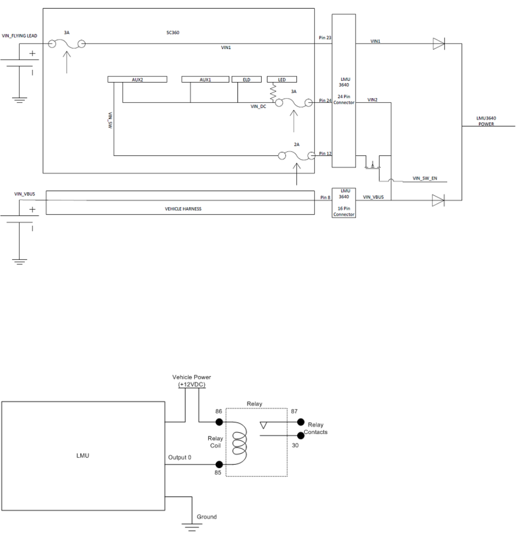
3.4.3 Outputs
The LMU’s and ioPOD;s outputs are designed to drive external relays. These outputs provide a high-current, open-collector driver that can sink up
to 150 mA each. These drivers may be used to drive external relays that can then control vehicle functions such as door locks, fuel shut-off valves,
sirens and lights. If additional current is required to drive the relays, external circuitry can be added to source the current. This diagram is a typical
use of an output to drive a relay.
Sample Relay Wiring
3.4.4 Status LEDs
The LMU-3640™ is equipped with 3 Status LEDs; one for GPS, one for COMM (wireless network status), one for GPS, and one for WiFi. The
LEDs use the following colors to indicate service:
Status LEDs

9/27/2017 LMU-3640 Hardware & Installation Guide - PULS Wiki
https://puls.calamp.com/wiki/LMU-3640_Hardware_%26_Installation_Guide 11/23
Status Color
GPS Green
Comm Orange
WiFi/BT Blue
4 Configuration and Activation
This section details how to quickly get an LMU-3640™ provisioned and configured to point at a specific server. It is assumed that a PEG script has
already been created and is being managed through LMU Manager or PULS™, the CalAmp Maintenance System.
We are making three assumptions to simplify the setup process:
You have created, installed and configured an LM Direct™ Server to receive messages from the LMU-3640™. (See LM Direct™
Reference Guide for details)
You are using the standard wiring harness from CalAmp and the serial port expansion harness.
You have created a HyperTerminal or Putty session.
You have contacted the CalAmp sales team regarding the network availability of the LMU-3640™. This device may not be supported
for all the carriers or networks listed in this section (CDMA-Verizon, CDMA-Sprint, HSPA, GSM), for product availability consult the
CalAmp sales team.
4.1 Quick Start - General Config
All LMU-3640™s must go through a common step during the configuration and provisioning process. Specifically, this is pointing the LMU to
your LM Direct™ server, either via IP or a URL.
This configuration process is accomplished via a series of AT Commands:
1. Power up the LMU-3640™ and connect a serial cable from the LMU to your laptop
2. Open a terminal session to the LMU-3640™
3. Enter the address of the LM Direct™ server:
Where ddd.ddd.ddd.ddd is the publicly addressable IPV4 address of your LM Direct™ server and ppppp is the UDP port number.
4. Alternatively if a URL has been set up for your LM Direct™ server, the LMU may be programmed with:
Where myURL.MyCompany.com is the URL assigned to the server.
5. Enter ATIC to verify the correct settings are displayed for your Inbound Server.
This configuration process is accomplished via a series of SMS Commands:
1. Power up the LMU-3640™ and your handset
2. From the handset, send an SMS message to the LMU-3640™ phone number:
Where ddd.ddd.ddd.ddd is the publicly addressable IPV4 address of your LM Direct™ server and ppppp is the UDP port number
3. Alternatively if a URL has been set up for your LM Direct™ server, the LMU may be programmed with:
AT$APP PARAM 2319,0,ddd.ddd.ddd.ddd
AT$APP PARAM 768,0,ddd.ddd.ddd.ddd (32-bit products only)
AT$APP PARAM 769,0,ppppp
AT$APP PARAM 2319,0,myURL.MyCompany.Com