California Eastern Laboratories WB4343WF3SP2 WiFi/Bluetooth/Bluetooth Smart Mini Module User Manual MeshConnect
California Eastern Laboratories WiFi/Bluetooth/Bluetooth Smart Mini Module MeshConnect
Exhibit D Users Manual per 2 1033 b3
1
This document is subject to change without notice.
Document No: 0021-00-07-00-000 (Issue B)
Date Published: May 23, 2016
DESCRIPTION
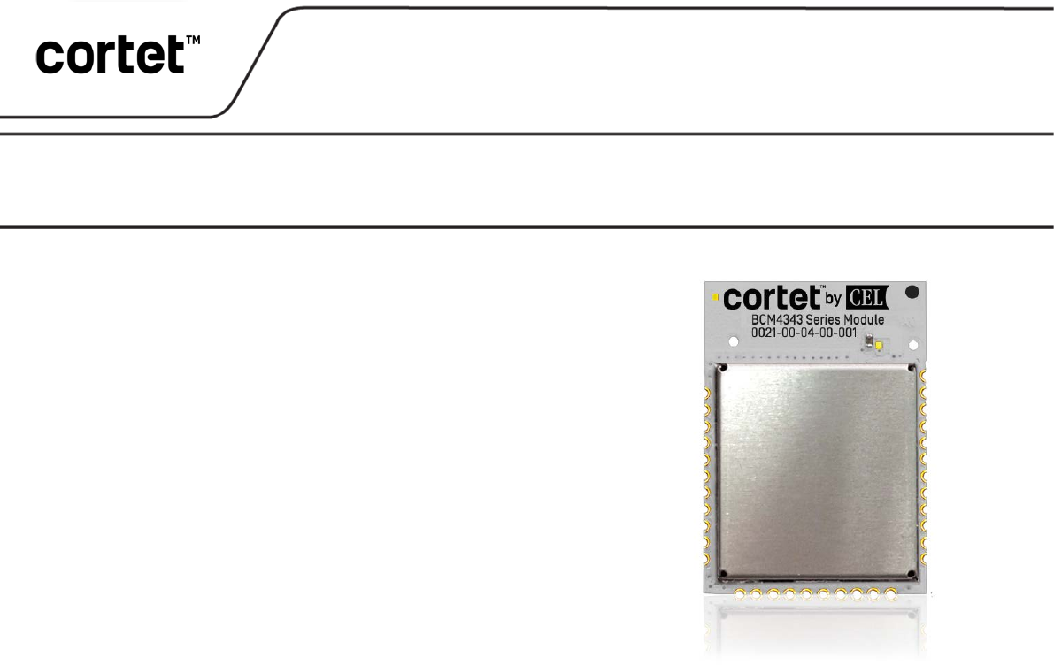
The WB4343W and W43364 Wi-Fi®/Bluetooth®/Bluetooth Smart Mini
Modules are complete standalone solutions for designers looking to
take advantage of the high data rate of Wi-Fi, to interface to legacy
Bluetooth Classic devices already in the field, and to utilize the low
power consumption and mesh network capabilities of Bluetooth
Smart. They eliminate design risk and significantly reduce time-to-
market for a multitude of M2M applications.
These devices are footprint-compatible with CEL’s existing line of
ZigBee®, Thread, and Bluetooth®-based modules, allowing solutions
which easily transition between multiple wireless networking
standards via drop-in compatible module hardware.
The WB4343W and W43364 Mini Module family consists of four
drop-in compatible devices so the feature set can be optimized for
your application. Options include Wi-Fi/Bluetooth/Bluetooth Smart
(WB4343W) or Wi-Fi only (W43364) radios, plus different MCU
memory sizes (STM32F411 MCU with 512kB flash/128kB RAM or
STM32F412 MCU with 1MB flash/256kB RAM).
Based on the Broadcom BCM4343W and BCM43364 transceivers and the ST Micro STM32 microprocessor, the
Cortet Mini Modules combine the BCM43xxx's 32-bit ARM® Cortex®-M3 MCU, integrated ROM & RAM, 2.4 GHz
radio, LNA, PA, and internal transmit/receive RF switch with an ultra low power, high performance 32-bit ARM®
Cortex®-M4F MCU with FPU, 512KB or 1MB flash, 128kB or 256kB SRAM, and all necessary crystals and filtering.
These devices leverage the world-class WICED™ SDK toolset from Broadcom, and are capable of running the
WICED stack plus the product application code without requiring an additional microprocessor. They are optimized
for small size and low power consumption, and can be run directly from a rechargeable mobile platform battery. They
include Broadcom’s Enhanced Collaborative Coexistence algorithms and hardware mechanisms, allowing for an
extremely collaborative Wi-Fi and Bluetooth coexistence.
KEY FEATURES
• Wi-Fi (802.11 b/g/n, single stream)
• Bluetooth 2.1+EDR & 3.0, Bluetooth 4.1 (BLE)
• Fully Compatible with the Broadcom WICED SDK
• Dual MCUs (32-bit ARM® Cortex®-M3 & -M4F)
• 512 kB or 1MB Flash, 128kB or 256kB SRAM
• Up to 25 GPIOs, including SPI, USART, I2C, ADCs
and timers
• Internal antenna or RF port for external antenna
• Mini footprint: 0.940” x 0.655” (23.9 x 16.6mm)
• Footprint-compatible with CEL's Bluetooth, ZigBee,
and Thread module family
• FCC, IC, Wi-Fi Alliance, and Bluetooth SIG certified
APPLICATIONS
• Connected Home & Appliances
• Building Control & Automation
• Lighting
• Security
• Wireless Sensor Networks
• Wireless Audio & Video
• Remote Health and Wellness Monitoring
• General M2M Wireless Networking
Wi-Fi®/Bluetooth®/Bluetooth Smart Mini Module
WB4343WFxSP2
, W43364FxSP2
Broadcom
TM
Transceiver-Based Module
PRELIMINARY DATASHEET
Embedded Wireless LAN Controller Module

WB4343WFxSP2, W43364FxSP2
This document is subject to change without notice.
Document No: 0021-00-07-00-000 (Issue B)
2
PRELIMINARY DATASHEET
TABLE OF CONTENTS
DESCRIPTION ...................................................................................................................................... 1
KEY FEATURES ..................................................................................................................................... 1
APPLICATIONS ..................................................................................................................................... 1
TABLE OF CONTENTS ........................................................................................................................... 2
DEVELOPMENT TOOLS......................................................................................................................... 3
BLOCK DIAGRAM................................................................................................................................. 3
ORDERING INFORMATION ................................................................................................................... 4
ANTENNA ............................................................................................................................................ 4
TRANSCEIVER IC .................................................................................................................................. 5
MICROPROCESSOR .............................................................................................................................. 5
SOFTWARE/FIRMWARE ....................................................................................................................... 5
ABSOLUTE MAXIMUM RATINGS .......................................................................................................... 6
RECOMMENDED OPERATING CONDITIONS .......................................................................................... 6
DC CHARACTERISTICS .......................................................................................................................... 7
RF CHARACTERISTICS ........................................................................................................................... 7
I/O PIN ASSIGNMENTS .......................................................................................................................11
CEL MINI MODULE COMPATIBILITY.....................................................................................................12
MODULE DIMENSIONS .......................................................................................................................12
MODULE LAND FOOTPRINT ................................................................................................................13
PROCESSING ......................................................................................................................................14
AGENCY CERTIFICATIONS ...................................................................................................................16
SHIPMENT, HANDLING AND STORAGE ................................................................................................17
QUALITY ............................................................................................................................................17
REVISION HISTORY .............................................................................................................................18
DISCLAIMER .......................................................................................................................................18
WB4343WFxSP2, W43364FxSP2
This document is subject to change without notice.
Document No: 0021-00-07-00-000 (Issue B)
3
PRELIMINARY DATASHEET
DEVELOPMENT TOOLS
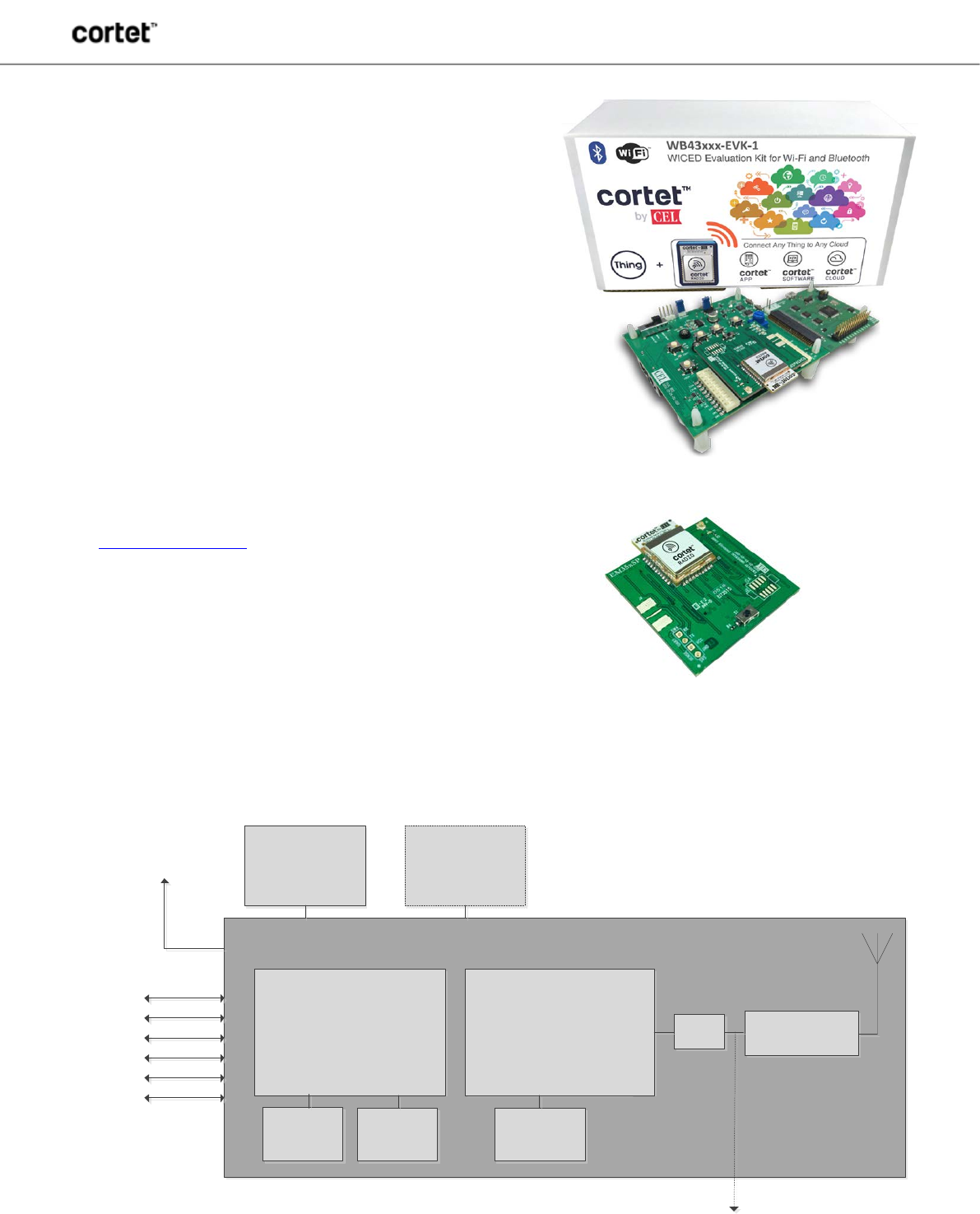
Cortet Radio WICED Evaluation Kit for Wi-Fi and Bluetooth
The Cortet Radio WICED Evaluation Kit is designed for rapid
evaluation of the WB43xxxSP2 family. Based on the best-in-class
Broadcom WICED software development environment, the WB43xxx
Evaluation Kit is a comprehensive solution for software prototyping
and making hardware measurements.
Kit contents:
• Evaluation board with push buttons, LEDs, analog inputs,
JTAG over USB interface for software programming and
debug, external voltage inputs, ammeter interface, and
GPIO breakout pins
• Daughtercard with WB4343WF3SP2-1C module (Wi-Fi/
Bluetooth transceiver + STM32F411 MCU, including 512kB
flash and 128kB RAM)
• Programming interface cable
• Link to online documentation
Visit cortet.cel.com/wb4343 for more information.
The Cortet Radio WICED Evaluation Kit utilizes a modular
daughtercard architecture. Once the base kit (WB43XXX-EVK-1) has
been purchased, WB43xxxSP2 daughtercards containing a header
compatible with the WB43xxx Evaluation Kit can be ordered separately
for all members of the WB43xxxSP2 module family. See ordering
information below for more details.
BLOCK DIAGRAM
ARM Cortex-M4F BCM43xxx
26MHz
Crystal
37.4MHz
Crystal
LPF
1MB
External Flash
Antenna match
JTAG Connector
(SW debug)
VCC
I2C
SPI
TIMER
USART
ADC
GPIO
CEL Module
Optional External
Antenna
32kHz
Crystal
WB43xxx Evaluation Kit
Add-on daughtercard for use
with WB43xxx Evaluation Kit
WB4343WFxSP2, W43364FxSP2
This document is subject to change without notice.
Document No: 0021-00-07-00-000 (Issue B)
4
PRELIMINARY DATASHEET
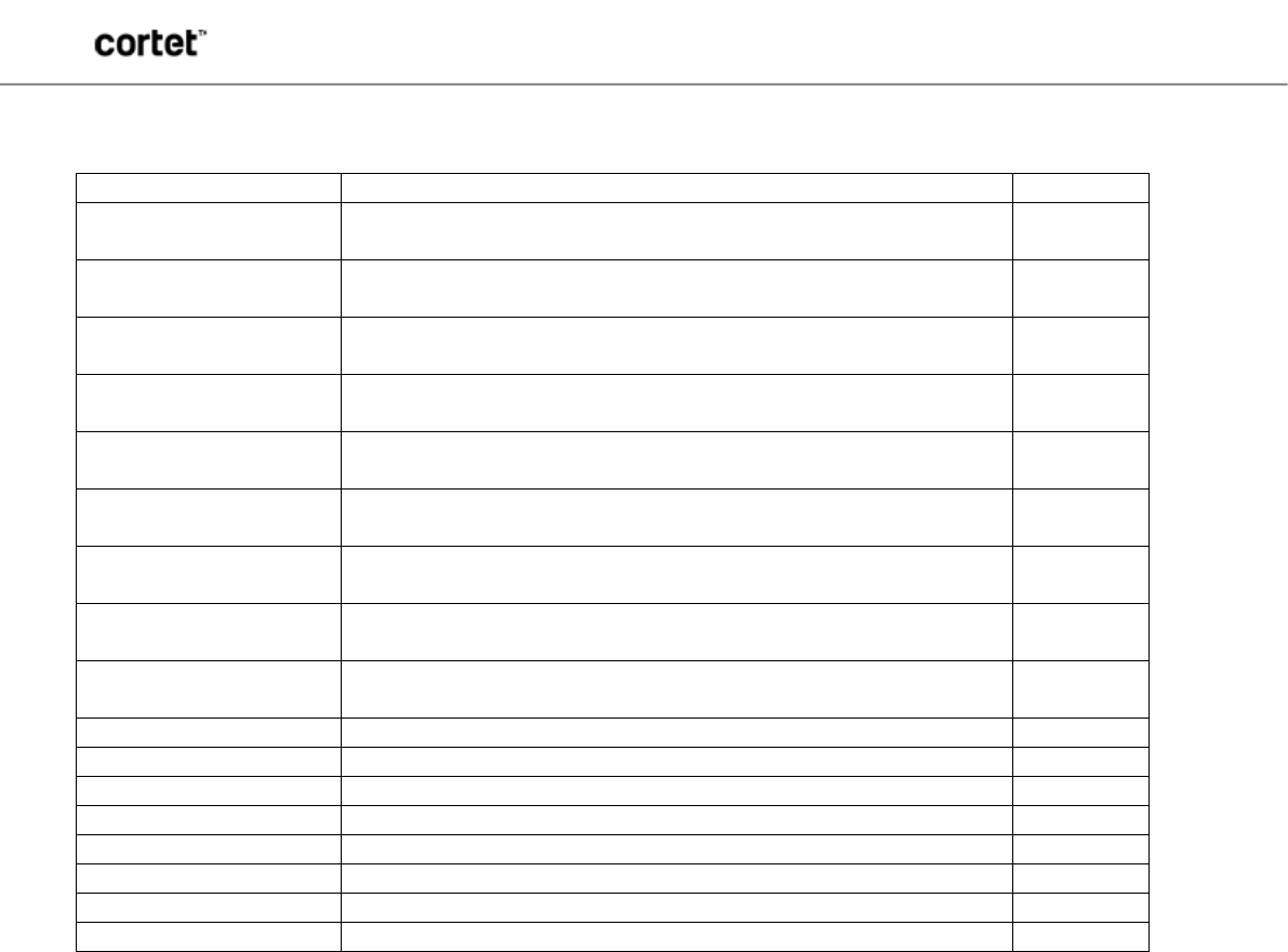
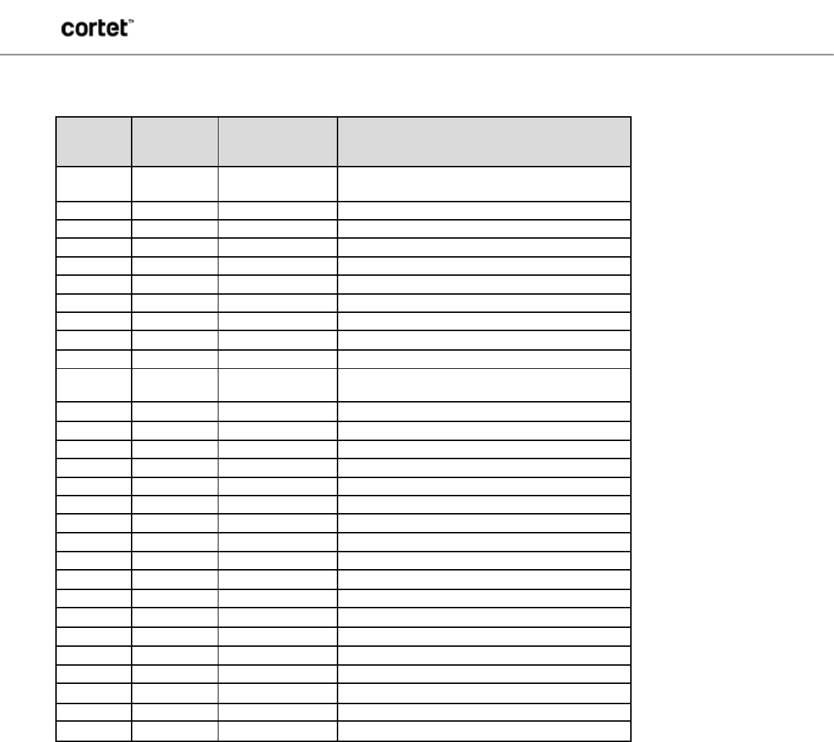
ORDERING INFORMATION
Order Number
Description
Min/Multiple
WB4343WF3SP2-1-R Wi-Fi/BT Module, BCM4343W Transceiver + STM32F411 MCU (512kB
flash, 128kB RAM), Trace Antenna
600
WB4343WF3SP2-1C-R Wi-Fi/BT Module, BCM4343W Transceiver + STM32F411 MCU (512kB
flash, 128kB RAM), Castellation Pin for External Antenna
600
WB4343WF4SP2-1-R Wi-Fi/BT Module, BCM4343W Transceiver + STM32F412 MCU (1MB
flash, 256kB RAM), Trace Antenna
600
WB4343WF4SP2-1C-R Wi-Fi/BT Module, BCM4343W Transceiver + STM32F412 MCU (1MB
flash, 256kB RAM), Castellation Pin for External Antenna
600
W43364F3SP2-1-R Wi-Fi Module, BCM43364 Transceiver + STM32F411 MCU (512kB flash,
128KB RAM), Trace Antenna
600
W43364F3SP2-1C-R Wi-Fi Module, BCM43364 Transceiver + STM32F411 MCU (512kB flash,
128KB RAM), Castellation Pin for External Antenna
600
W43364F4SP2-1-R Wi-Fi Module, BCM43364 Transceiver + STM32F412 MCU (1MB flash,
256KB RAM), Trace Antenna
600
W43364F4SP2-1C-R Wi-Fi Module, BCM43364 Transceiver + STM32F412 MCU (1MB flash,
256KB RAM), Castellation Pin for External Antenna
600
WB43XXX-EVK-1 WB43xxx Evaluation Kit - Universal Eval Board + WB43xxx Programming
Fixture, pre-populated with WB4343F3SP2-1C-EVB on daughtercard
1
WB4343WF3SP2-1-EVB
WB4343WF3SP2-1 on daughtercard for use with WB43xxx-EVK-1
1
WB4343WF3SP2-1C-EVB
WB4343WF3SP2-1C on daughtercard for use with WB43xxx-EVK-1
1
WB4343WF4SP2-1-EVB
WB4343WF4SP2-1 on daughtercard for use with WB43xxx-EVK-1
1
WB4343WF4SP2-1C-EVB
WB4343WF4SP2-1C on daughtercard for use with WB43xxx-EVK-1
1
W43364F3SP2-1-EVB
W43364F3SP2-1 on daughtercard for use with WB43xxx-EVK-1
1
W43364F3SP2-1C-EVB
W43364F3SP2-1C on daughtercard for use with WB43xxx-EVK-1
1
W43364F4SP2-1-EVB
W43364F4SP2-1 on daughtercard for use with WB43xxx-EVK-1
1
W43364F4SP2-1C-EVB
W43364F4SP2-1C on daughtercard for use with WB43xxx-EVK-1
1
ANTENNA
The Cortet Mini Modules include an integrated Printed Circuit Board (PCB) trace antenna. An optional configuration which uses
a castellation pin on the module allows the user to connect to an external antenna. The WB43xxxSP2 family has been certified
with the PCB trace antenna only. The PCB antenna employs a topology that is compact and highly efficient. To maximize
range, an adequate ground plane must be provided on the host PCB. Correctly positioned, the ground plane on the host PCB
will contribute significantly to the antenna performance.
For optimum antenna performance, the Cortet Mini Module should be mounted with the PCB trace antenna overhanging the
edge of the host board. To further improve performance, a ground plane may be placed on the host board under the module, up
to the antenna but not extending under the antenna (a minimum of 1.5" x 1.5" is recommended). The installation of an
uninterrupted ground plane on a layer directly beneath the module will also allow traces to be routed under the layer. Refer to
the application note Mini Modules Hardware Design Guidelines for more details. CEL can assist with your PCB layout.
The following are some design guidelines to help ensure optimal antenna performance:
• The antenna portion of the Mini Module should hang over the host board so that there is not any additional
PCB under the antenna.
• Never place the antenna close to metallic objects
• In the final assembly, ensure that wiring and other components are not placed near the antenna
• Do not place the antenna in a metallic or metalized plastic enclosure
• Keep plastic enclosures a minimum of 1cm away from the antenna in any direction
Under Industry Canada regulations, this radio transmitter may only operate using an antenna of a type and maximum (or lesser)
gain approved for the transmitter by Industry Canada. To reduce potential radio interference to other users, the antenna type and
its gain should be so chosen that the equivalent isotropically radiated power (e.i.r.p.) is not more than that necessary for
successful communication.

WB4343WFxSP2, W43364FxSP2
This document is subject to change without notice.
Document No: 0021-00-07-00-000 (Issue B)
5
PRELIMINARY DATASHEET
Conformément à la réglementation d'Industrie Canada, le présent émetteur radio peut fonctionner avec une antenne d'un type et
d'un gain maximal (ou inférieur) approuvé pour l'émetteur par Industrie Canada. Dans le but de réduire les risques de brouillage
radioélectrique à l'intention des autres utilisateurs, il faut choisir le type d'antenne et son gain de sorte que la puissance isotrope
rayonnée équivalente (p.i.r.e.) ne dépasse pas l'intensité nécessaire à l'établissement d'une communication satisfaisante.
TRANSCEIVER IC
The WB43xxxSP2 family utilizes the BCM4343W or BCM43364 transceiver (WB4343WFxSP2 or W43364FxSP2 models
respectively), which is a highly integrated 2.4GHz WLAN IEEE 802.11 b/g/n MAC/baseband transceiver. It integrates a power
amplifier (PA) and a low-noise amplifier (LNA) for best-in-class receiver sensitivity and an internal transmit/receive RF switch.
The BCM4343W transceiver supports the Wi-Fi, Bluetooth, and Bluetooth Smart protocols, while the BCM43364 transceiver
supports Wi-Fi only.
Both transceivers also contain an ARM® Cortex®-M3 32-bit RISC microprocessor, with 640kB ROM and 512kB RAM for running
software from the Link Control Layer up to the Host Controller Interface.
MICROPROCESSOR
The Cortet Mini Modules contain a STM32 microprocessor from ST Micro, which is a 32-bit ARM® Cortex®-M4F processor
running at 100MHz. The WB43xxxF3 utilizes the STM32F411 with 512kB of flash and 128kB of SRAM, and the WB43xxxF4
utilizes the STM32F412 with 1MB of flash and 256kB of SRAM. Both MCUs support a rich set of peripherals, including SPI,
USART, I2C, 12-bit ADCs and timers. This ARM® Cortex®-M4F core features a floating point unit (FPU) which supports all ARM®
single-precision data-processing instructions and data types. It also implements a full set of DSP instructions and a memory
protection unit (MPU) which enhances application security.
With the resources of the on-board STM32 microprocessor, the WB43xxxF3 and WB43xxxF4 Mini Modules are capable of
running the full Broadcom WICED stack plus the product application code, providing a full standalone solution. The WB43xxxF4
is ideal for resource-intensive applications like a Wi-Fi/Bluetooth Smart Bridge with support for Amazon Web Services and Apple
HomeKit, while the WB43xxxF3 is a more cost-effective solution for Wi-Fi enabled end devices.
SOFTWARE/FIRMWARE
The Cortet Mini Modules utilize the WICED software development environment, which allows designers to quickly and easily
integrate Wi-Fi and Bluetooth connectivity into any product. WICED is an open-source build system based on GNU ‘make’ and
will also run on commercial toolchains such as IAR. It has a GUI development environment based on Eclipse CDT, and supports
a JTAG programmer and single-step, thread-aware debugger based on OpenOCD and gdb. The WICED platform offers several
RTOS/TCP stack options, has a simple API for accessing hardware peripherals, and includes advanced security and networking
features like SSL/TLS and IPv4/IPv6 TCP/IP networking stacks. It is a production-ready application framework, including a
bootloader, flash storage API, over-the-air upgrades, factory reset, and a system monitor.
WB4343WFxSP2, W43364FxSP2
This document is subject to change without notice.
Document No: 0021-00-07-00-000 (Issue B)
6
PRELIMINARY DATASHEET
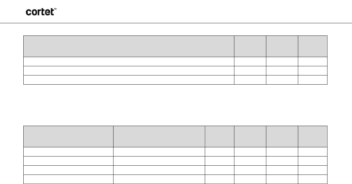
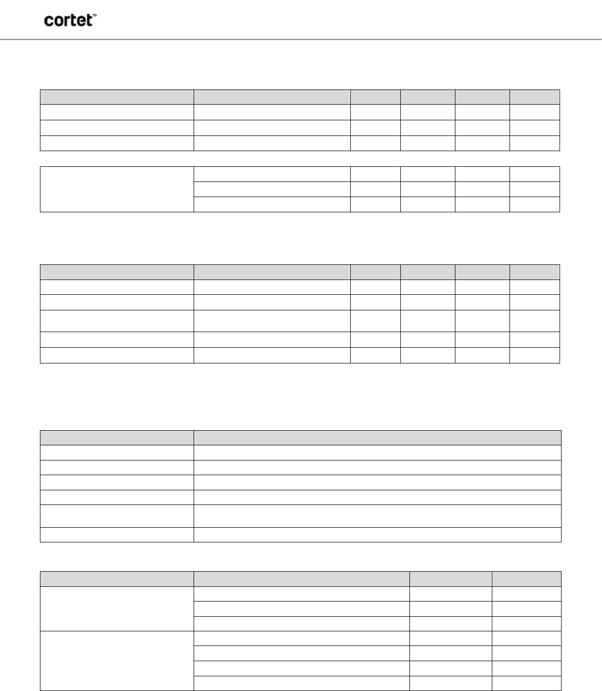
ABSOLUTE MAXIMUM RATINGS
Description Min Max Unit
Storage Temperature
-40
85
°C
Voltage Ripple (Max. value not to exceed operating voltage)
2
%
Power Supply Voltage
4
V
RECOMMENDED OPERATING CONDITIONS
Symbol Parameter Min Typ Max Unit
Frequency 2405
2484 MHz
Power Supply Voltage
3.0 3.3 3.6 V
Operating Temperature -40
85 °C
Humidity Range Non condensing
95 %
WB4343WFxSP2, W43364FxSP2
This document is subject to change without notice.
Document No: 0021-00-07-00-000 (Issue B)
7
PRELIMINARY DATASHEET
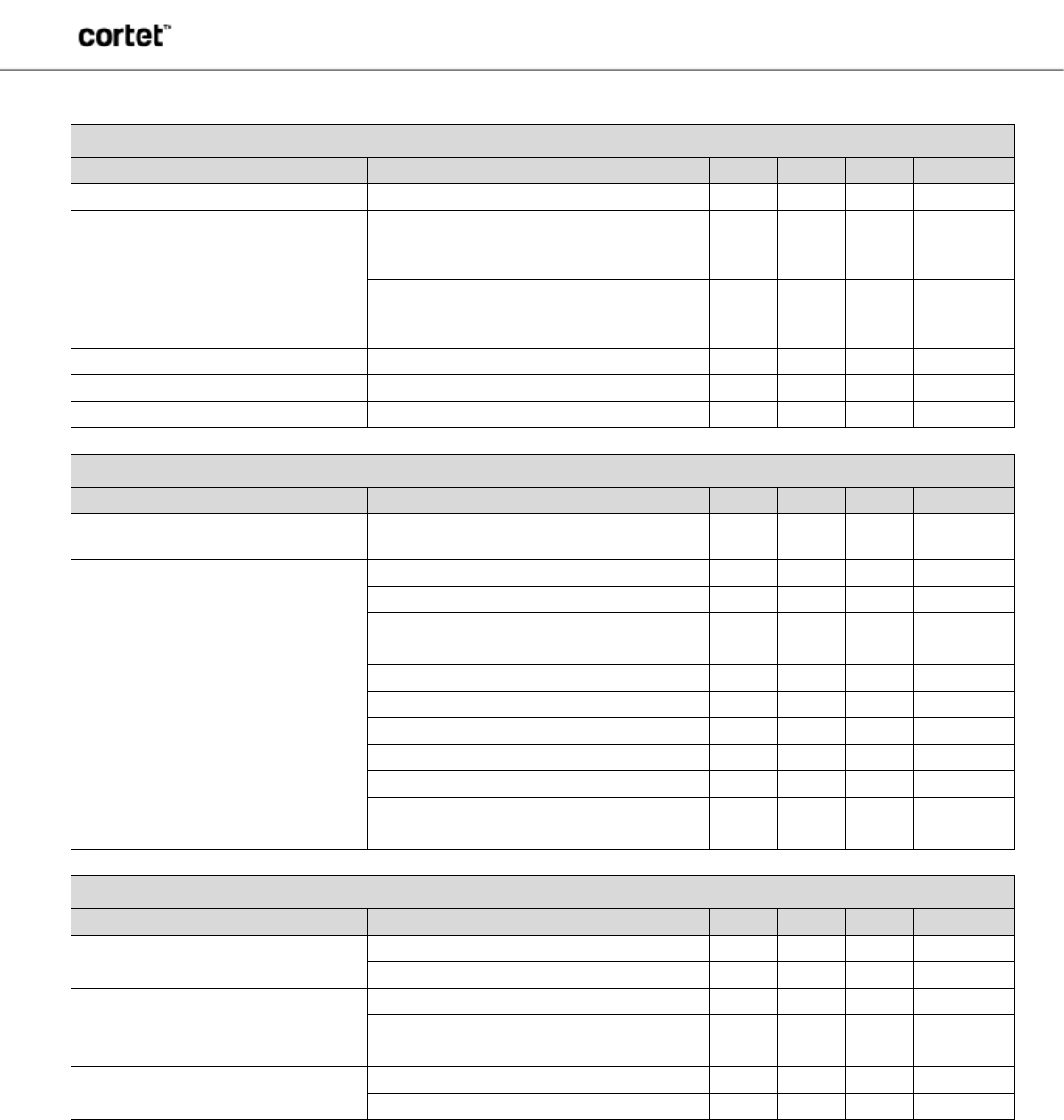
DC CHARACTERISTICS
(@ 25°C unless otherwise specified)
WLAN
Item
Condition
Min
Nom
Max
Unit
Tx mode (11b Max current) 11Mbps
300
mA
Tx mode (11g Max current) 54Mbps
275
mA
Tx mode (11n Max current) MCS7
275
mA
Rx mode
11b (11Mbps)
45
mA
11g (54Mbps)
45
mA
11n (MCS7)
46
mA
BLUETOOTH
(WB4343W variants only)
Condition: +10dBm
Item
Condition
Min
Nom
Max
Unit
Tx Mode
3DH5
30
mA
RX Mode
3DH5
20
mA
BLE Scan
1.28 s. interval with 11.25 ms
window
350
µA
BLE Adv. – Unconnectable 1 sec.
270
µA
BLE Connected 1 sec.
250
µA
RF CHARACTERISTICS
Wi-Fi RF SPECIFICATION
Features
Description
WLAN Standards IEEE 802 Part 11 b/g/n (802.11b/g/n single stream)
Antenna Port Support Single Antenna for Wi-Fi / Diversity with external switch
Frequency Band 2.4000 – 2.497 GHz (2.4 GHz ISM Band)
Number of selectable Sub CH 14 channels
Modulation
OFDM, DSSS (Direct Sequence Spread Spectrum), DBPSK, DQPSK, CCK , 16QAM,
64QAM, 256QAM
Supported rates 1, 2, 5.5,11, 6, 9,12, 24, 36, 48, 54 Mbps & HT20 MCS0~7
Item
Condition
Nom
Unit
Maximum RX Input Level
with PER < 8%@11 Mbps -10 dBm
with PER < 10%@54 Mbps -20 dBm
with PER < 10%@MCS7 -20 dBm
Output Power
17dBm @ 802.11b 17 dBm
13dBm @ 802.11g
13
dBm
12dBm @ 802.11n 12 dBm
@ 802.11n (256QAM) 10 dBm
The RF performance reported above assumes a default supply voltage of 3.3V.
WB4343WFxSP2, W43364FxSP2
This document is subject to change without notice.
Document No: 0021-00-07-00-000 (Issue B)
8
PRELIMINARY DATASHEET
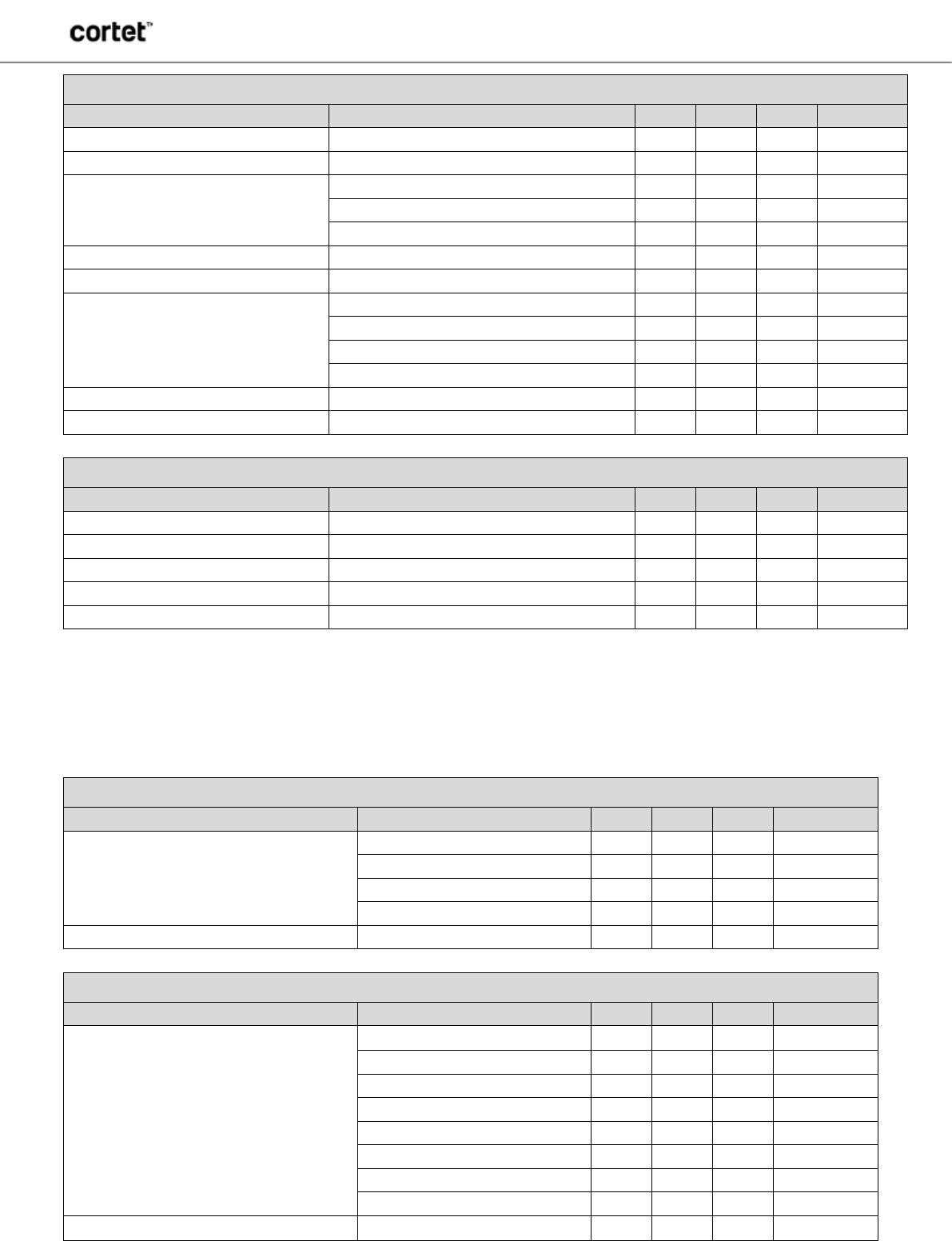
TRANSMITTER SPECIFICATION
802.11b Transmitter
Item
Condition
Min.
Typ.
Max.
Unit
Transmit Output Power 1M/2M/5.5M/11M
17
dBm
Transmit spectrum mask
Fc-22MHz<F<Fc-11MHz &
Fc+11MHz<F<Fc+22MHz(1/2/5.5/11Mbps;
channel 1~13) -30 dBc
F<Fc-22MHz
&F>Fc+22MHz(1/2/5.5/11Mbps; channel
1~13) -50 dBc
Transmit power - on 10% ~ 90 %
0.3 2 µs
Transmit power - down 90% ~ 10 %
1.5 2 µs
Transmit modulation accuracy 1/2/5.5/11 Mbps
-17 -10 dB
802.11g Transmitter
Item
Condition
Min.
Typ.
Max.
Unit
Transmit Output Power 6M/9M/12M/18M/24M/36M/48M/54M 13 dBm
Transmit spectrum mask
@ 11MHz
-20 dBc
@ 20MHz
-28 dBc
@30MHz
-40 dbc
Transmit modulation accuracy
6Mbps
-5 dB
9Mbps
-8 dB
12Mbps
-10 dB
18Mbps
-13 dB
24Mbps
-16 dB
36Mbps
-19 dB
48Mbps
-22 dB
54Mbps
-25 dB
802.11n Transmitter
Item
Condition
Min.
Typ.
Max.
Unit
Transmit Output Power HT20 MCS 0~7
12
dBm
HT20 MCS7
10
dBm
Transmit spectrum mask
@ 11MHz
-20 dBc
@ 20MHz
-28 dBc
@30MHz
-40 dbc
Transmit modulation accuracy HT20 MCS 0~7
-27 dB
HT20 MCS7
-32 dB
WB4343WFxSP2, W43364FxSP2
This document is subject to change without notice.
Document No: 0021-00-07-00-000 (Issue B)
9
PRELIMINARY DATASHEET
Bluetooth Transmitter
(WB4343W variants only)
Item
Condition
Min.
Typ.
Max.
Unit
Frequency Range
2402
2480 MHz
Channel Spacing
1
MHz
Transmit Output Power
GFSK
10
dBm
QPSK
6
dBm
BPSK
6
dBm
Initial Carrier Freq. Tolerance
25 75 kHz
Lock Time
72
µS
Frequency Drift
DH1 Packet
8 25 kHz
DH3 Packet
8 40 kHz
DH5 Packet
8 40 kHz
Drift Rate
5 20 KHz/50µS
Frequency Deviation 00001111 sequence 140 155 175 kHz
10101010 sequence 115 140
kHz
Bluetooth Low Energy Transmitter
(WB4343W variants only)
Item
Condition
Min.
Typ.
Max.
Unit
Frequency Range
2402
2480 MHz
Transmit Output Power
8
dBm
Mod Char: delta f1 average
225 225 275 kHz
Mod Char: delta f2 max
99.9
%
Mod Char: ratio
0.8 0.95
%
RECEIVER SPECIFICATION
802.11b Receiver
Item
Condition
Min.
Typ.
Max.
Unit
Minimum Input Level Sensitivity
(PER < 8%)
1Mbps -80 -93
dBm
2Mbps -80 -91
dBm
5.5Mbps -76 -89
dBm
11Mbps -76 -86
dBm
Maximum Input Level (PER < 8%) 1/2/5.5/11Mbps
-10 dBm
802.11g Receiver
Item
Condition
Min.
Typ.
Max.
Unit
Minimum Input Level Sensitivity
(PER < 10%)
6Mbps -82 -88
dBm
9Mbps -81 -87
dBm
12Mbps -79 -85
dBm
18Mbps -77 -83
dBm
24Mbps -74 -80.5
dBm
36Mbps -70 -78.5
dBm
48Mbps -66 -74
dBm
54Mbps -65 -72
dBm
Maximum Input Level (PER < 10%) 6/9/12/18/24/36/48/54Mbps
-20 dBm
WB4343WFxSP2, W43364FxSP2
This document is subject to change without notice.
Document No: 0021-00-07-00-000 (Issue B)
10
PRELIMINARY DATASHEET
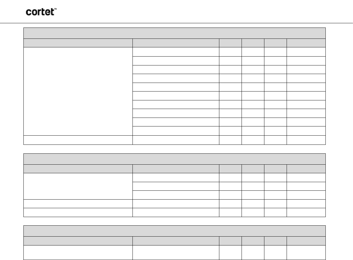
802.11n Receiver
Item
Condition
Min.
Typ.
Max.
Unit
Minimum Input Level Sensitivity
(PER < 10%)
HT20, MCS0 -82 -87.5
dBm
HT20, MCS1 -79 -84
dBm
HT20, MCS2 -77 -82
dBm
HT20, MCS3 -74 -80.5
dBm
HT20, MCS4 -70 -77
dBm
HT20, MCS5 -66 -72
dBm
HT20, MCS6 -65 -71
dBm
HT20, MCS7 -64 -70
dBm
256-QAM R 3/4
-68
dBm
256-QAM R=5/6
-66
dBm
Maximum Input Level (PER < 10%) MSC0~MSC7
-20 dBm
Bluetooth Receiver
(WB4343W variants only)
Item
Condition
Min.
Typ.
Max.
Unit
Minimum Input Level Sensitivity
(PER < 10%)
GFSK, 0.1% BER, 1Mbps
-91
dBm
π/4-DQPSK, 0.01% BER, 2Mbps
-93
dBm
8-DPSK, 0.01% BER, 3Mbps
-87
dBm
Input IP3
-16
dBm
Maximum Input Level
-20 dBm
Bluetooth Low Energy Receiver
(WB4343W variants only)
Item
Condition
Min.
Typ.
Max.
Unit
Minimum Input Level Sensitivity with Dirty
Transmitter
GFSK, 0.1% BER, 1Mbps
-94
dBm
WB4343WFxSP2, W43364FxSP2
This document is subject to change without notice.
Document No: 0021-00-07-00-000 (Issue B)
11
PRELIMINARY DATASHEET
I/O PIN ASSIGNMENTS
Refer to the STM32 datasheet for pin functionality details.
Module Pin
Number
STM32F41x
UFBGA100
Pin Number Pin Name Notes
1, 2, 12, 31,
33 D3,F2,J1,F12,
F11, GND
3
J2
PC1
4 H2 Reset
5
A4
BOOT0
6
L6
PB2/BOOT1
7
L2
PA0/WAKE
8
B12
PA11/USART1_CTS
9
A12
PA12/USART1_RTS
10 M4 PA7/SPI1_MOSI
11
L4
PA6/SPI1_MISO
13 C4,E2,G2,M1,
G12,G11 VDD Input power to the module.
14
K4
PA5/SPI1_SCK
15
M3
PA4/SPI1_NSS
16
B5
PB6
17
B4
PB7
18 H1 PC0
19
D10
PA9/USART1_TX
20
C12
PA10/USART_RX
21 A10 PA14/JTCK
22
A8
PB3/JTDO
23
A9
PA15/JTDI
24 A11 PA13/JTMS
25
J3
PC2
26 K2 PC3/ADC1_13 Could be A/D or GPIO
27 A7 PB4/JRST
28
L3
PA3/ADC1_3
Could be A/D or GPIO
29 K3 PA2/ADC1_2 Could be A/D or GPIO
30
M2
PA1/ADC1_1
Could be A/D or GPIO
32 - RF OUT Castellation Pin for External Antenna
NOTE: I/O PINOUTS ARE PRELIMINARY AND SUBJECT TO CHANGE.
CONTACT CEL BEFORE COMMITTING TO PCB LAYOUTS TO ENSURE THAT
PINOUT MAPPING MATCHES CEL'S FINAL DESIGN.
WB4343WFxSP2, W43364FxSP2
This document is subject to change without notice.
Document No: 0021-00-07-00-000 (Issue B)
12
PRELIMINARY DATASHEET
CEL MINI MODULE COMPATIBILITY
The geometry of the land pattern and location of the RF castellations is identical to CEL’s ZICM35x family of ZigBee/Thread and
B1010 Bluetooth Smart Mini Modules. The digital and analog mapping to develop a drop-in compatible solution is described
below:
Pin #
Function
ZICM35x
B1010
WB43xxx
Notes
4
Reset
RESET
N/C
RESET
5, 6
Low frequency crystal
PC6, PC7
N/C
N/C
Low frequency crystal is
internal for B1010 and
WB43xxx
7
Wake
PA7
WAKE
PA0
8, 9, 19, 20
Serial Controller 1
UART/SPI/I2C
Two wire UART/I2C
USART/I2C
10, 11, 14, 15
Serial Controller 2
SPI/I2C
I2C
SPI/I2C
16, 17, 21,
22, 23, 24, 27
Programming
Programming
Programming
Programming
28, 30
ADC
PB7, PB5
AIO[1], AIO[2]
PA3, PA1
29
Timer
PB6
PIO[11]
PA2
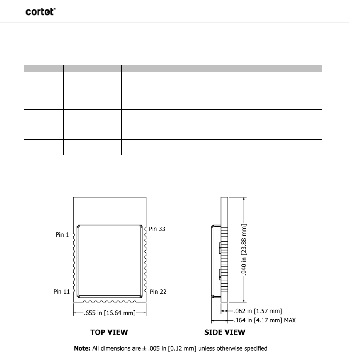
MODULE DIMENSIONS
WB4343WFxSP2, W43364FxSP2
This document is subject to change without notice.
Document No: 0021-00-07-00-000 (Issue B)
13
PRELIMINARY DATASHEET
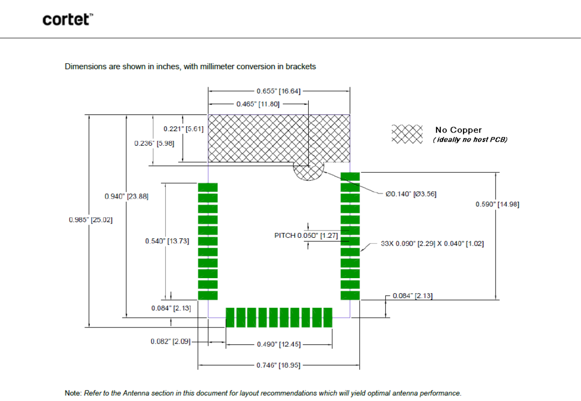
MODULE LAND FOOTPRINT
WB4343WFxSP2, W43364FxSP2
This document is subject to change without notice.
Document No: 0021-00-07-00-000 (Issue B)
14
PRELIMINARY DATASHEET
PROCESSING
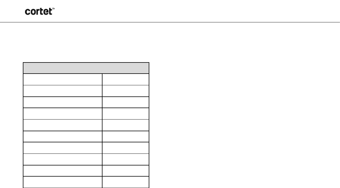
Recommended Reflow Profile
Parameter Values
Ramp Up Rate (from Tsoakmax to Tpeak)
3º/sec max
Minimum Soak Temperature
150ºC
Maximum Soak Temperature
200ºC
Soak Time
60-120 sec
TLiquidus
217ºC
Time above TLiquidus
60-150 sec
Tpeak
250ºC
Time within 5º of Tpeak
20-30 sec
Time from 25º to Tpeak
8 min max
Ramp Down Rate
6ºC/sec max
Pb-Free Solder Paste
Use of “No Clean” soldering paste is strongly recommended, as it does not require cleaning after the soldering process.
Note: The quality of solder joints on the castellations ("half vias") where they contact the host board should meet the
appropriate IPC Specification. See the Castellated Terminations Section in the latest IPC-A-610 Acceptability of
Electronic Assemblies document.
Cleaning
In general, cleaning the populated module is strongly discouraged. Residuals under the module cannot be easily removed with
any cleaning process.
• Cleaning with water can lead to capillary effects where water is absorbed into the gap between the host
board and the module. The combination of soldering flux residuals and encapsulated water could lead to short circuits
between neighboring pads. Water could also damage any stickers or labels.
• Cleaning with alcohol or a similar organic solvent will likely flood soldering flux residuals into the two
housings, which is not accessible for post-washing inspection. The solvent could also damage any stickers or labels.
• Ultrasonic cleaning could damage the module permanently.
The best approach is to consider using a “No Clean” solder paste and eliminate the post-soldering cleaning step.
Optical Inspection
After soldering the module to the host board, consider optical inspection to check the following:
• Proper alignment and centering of the module over the pads
• Proper solder joints on all pads
• Excessive solder or contacts to neighboring pads or vias
Repeating Reflow Soldering
Only a single reflow soldering process is encouraged for host boards.

WB4343WFxSP2, W43364FxSP2
This document is subject to change without notice.
Document No: 0021-00-07-00-000 (Issue B)
15
PRELIMINARY DATASHEET
Wave Soldering
If a wave soldering process is required on the host boards due to the presence of leaded components, only a single wave
soldering process is encouraged.
Hand Soldering
Hand soldering is possible. When using a soldering iron, follow IPC recommendations (reference document IPC-7711).
Rework
The Cortet module can be unsoldered from the host board. Use of a hot air rework tool should be programmable and the solder
joint and module should not exceed the maximum peak reflow temperature of 250ºC.
Caution
If temperature ramps exceed the reflow temperature profile, module and component damage may occur due to thermal shock.
Avoid overheating.
Warning
Never attempt a rework on the module itself (i.e., replacing individual components); such actions will terminate warranty
coverage.
Additional Grounding
Attempts to improve the module or the system grounding by soldering braids, wires or cables onto the module RF shield cover is
done at the customer's own risk. The ground pins at the module perimeter should be sufficient for optimum immunity to external
RF interference.

WB4343WFxSP2, W43364FxSP2
This document is subject to change without notice.
Document No: 0021-00-07-00-000 (Issue B)
16
PRELIMINARY DATASHEET
AGENCY CERTIFICATIONS
NOTE: Certifications are in process and pending final approval
FCC Compliance Statement Part 15.19, Section 7.15 of RSS-GEN
This device complies with Part 15 of the FCC Rules and with Industry Canada licence-exempt RSS Standards. Operation is
subject to the following two conditions:
1. This device may not cause harmful interference, and
2. This device must accept any interference received, including interference that may cause undesired operation.
Le présent appareil est conforme aux CNR d'Industrie Canada applicables aux appareils radio exempts de licence. L'exploitation
est autorisée aux deux conditions suivantes:
1. l'appareil ne doit pas produire de brouillage, et
2. l'utilisateur de l'appareil doit accepter tout brouillage radioélectrique subi, même si le brouillage est susceptible d'en
compromettre le fonctionnement.
Warning (Part 15.21)
Changes or modifications not expressly approved by CEL could void the user's authority to operate the equipment.
20cm Separation Distance
To comply with FCC/IC RF exposure limits for general population/uncontrolled exposure, the antenna(s) used for this transmitter
must be installed to provide a separation distance of at least 20cm from all persons and must not be co-located or operated in
conjunction with any other antenna or transmitter.
OEM Responsibility to the FCC and IC Rules and Regulations
The Cortet Mini Module has been certified per FCC Part 15 Rules and to Industry Canada license exempt RSS Standards for
integration into products without further testing or certification. To fulfill the FCC and IC certification requirements, the OEM of the
Cortet Module must ensure that the information provided on the Cortet label is placed on the outside of the final product. The
Cortet Mini Module is labeled with its own FCC ID number and IC ID number. If the FCC ID and the IC ID are not visible when
the module is installed inside another device, then the outside of the device into which the module is installed must also display a
label referring to the enclosed module. The exterior label can use wording such as the following
“Contains Transmitter Module FCC ID: W7Z-WB4343S”
“Contains Transmitter Module IC: 8254A-WB4343S"
The OEM of the Cortet Mini Module may only use the approved antennas (PCB Trace Antenna) that have been certified with this
module. The OEM of the Cortet Mini Module must test their final product configuration to comply with Unintentional Radiator
Limits before declaring FCC Compliance per Part 15 of the FCC Rules.
IC Certification — Industry Canada Statement
The term "IC" before the certification/registration number only signifies that the Industry Canada technical specifications were
met.
Certification IC — Déclaration d'Industrie Canada
Le terme "IC" devant le numéro de certification/d'enregistrement signifie seulement que les spécifications techniques Industrie
Canada ont été respectées.
Section 14 of RSS-210
The installer of this radio equipment must ensure that the antenna is located or pointed such that it does not emit RF field in
excess of Health Canada limits for the general population. Consult Safety Code 6, obtainable from Health Canada's website:
http://www.hc-sc.gc.ca/ewh-semt/pubs/radiation/radio_guide-lignes_direct-eng.php
L'article 14 du CNR-210
Le programme d'installation de cet équipement radio doit s'assurer que l'antenne est située ou orientée de telle sorte qu'il ne
pas émettre de champ RF au-delà des limites de Santé Canada pour la population générale. Consulter le Code de sécurité 6,
disponible sur le site Web de Santé Canada: http://www.hc-sc.gc.ca/ewh-semt/pubs/radiation/radio_guide-lignes_direct-eng.php
WB4343WFxSP2, W43364FxSP2
This document is subject to change without notice.
Document No: 0021-00-07-00-000 (Issue B)
17
PRELIMINARY DATASHEET
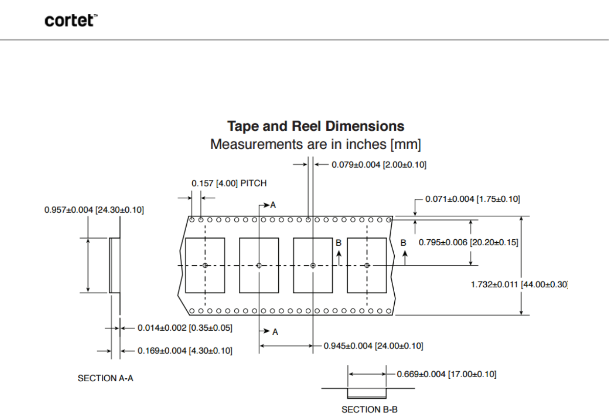
SHIPMENT, HANDLING AND STORAGE
Shipment
The Cortet modules are delivered in reels of 600 units. The reel diameter is 12.992 inches (330mm).
Handling
The Cortet modules are designed and packaged to be processed in an automated assembly line.
Warning
The Cortet modules contain highly sensitive electronic circuitry. Handling without proper ESD protection may destroy or damage
the module permanently.
Warning
The Cortet modules are moisture-sensitive devices. Appropriate handling instructions and precautions are summarized in J-STD-
033. Read carefully to prevent permanent damage due to moisture intake.
Moisture Sensitivity Level (MSL)
MSL 3, per J-STD-033
Storage
Storage/shelf life in sealed bags is 12 months at <40°C and <90% relative humidity.
QUALITY
CEL modules offer the highest quality at competitive prices. Our modules are manufactured in compliance with the IPC-A-610
specification, Class II. Our modules go through JESD22 qualification processes which includes high temperature operating life
tests, mechanical shock, temperature cycling, humidity and reflow testing.
CEL builds the quality into our products, giving our customers confidence when integrating our products into their systems.
WB4343WFxSP2, W43364FxSP2
This document is subject to change without notice.
Document No: 0021-00-07-00-000 (Issue B)
18
PRELIMINARY DATASHEET
REVISION HISTORY
Previous Versions
Changes to Current Version
Page(s)
0021-00-07-00-000
(Issue A) January 22, 2016 Initial Preliminary Data Sheet N/A
0021-00-07-00-000
(Issue B) May 23, 2016 Revisions to Entire Document N/A
DISCLAIMER
FOR MORE INFORMATION
For more information about CEL Cortet products and solutions, visit our website at cortet.cel.com.
TECHNICAL ASSISTANCE
For Technical Assistance, visit cortet.cel.com/tech-support.
The information in this document is current as of the published date. The information is subject to change without notice. For actual
design-in, refer to the latest publications of CEL Data Sheets or Data Books, etc., for the most up-to-date specifications of CEL
products. Not all products and/or types are available in every country. Please check with a CEL sales representative for availability and
additional information.
No part of this document may be copied or reproduced in any form or by any means without the prior written consent of CEL.
CEL assumes no responsibility for any errors that may appear in this document.
CEL does not assume any liability for infringement of patents, copyrights or other intellectual property rights of third parties by or arising
from the use of CEL products listed in this document or any other liability arising from the use of such products. No license, express,
implied or otherwise, is granted under any patents, copyrights or other intellectual property rights of CEL or others.
Descriptions of circuits, software and other related information in this document are provided for illustrative purposes in semiconductor
product operation and application examples. The incorporation of these circuits, software and information in the design of a customer’s
equipment shall be done under the full responsibility of the customer. CEL assumes no responsibility for any losses incurred by
customers or third parties arising from the use of these circuits, software and information.