California Eastern Laboratories ZICM357SP0 MeshConnect Mini-Module User Manual
California Eastern Laboratories MeshConnect Mini-Module Users Manual
UserManual.wiki
>
California Eastern Laboratories
>
ZICM357SP0 User Manual
>
Users Manual
Contents
1.
Users Manual
2.
External Antenna Manual V3
3.
Users Manual V2
Users Manual
Navigation menu
Upload a User Manual
Namespaces
Wiki Guide
HTML
PDF
Info
Views
User Manual
Discussion / Help
Navigation
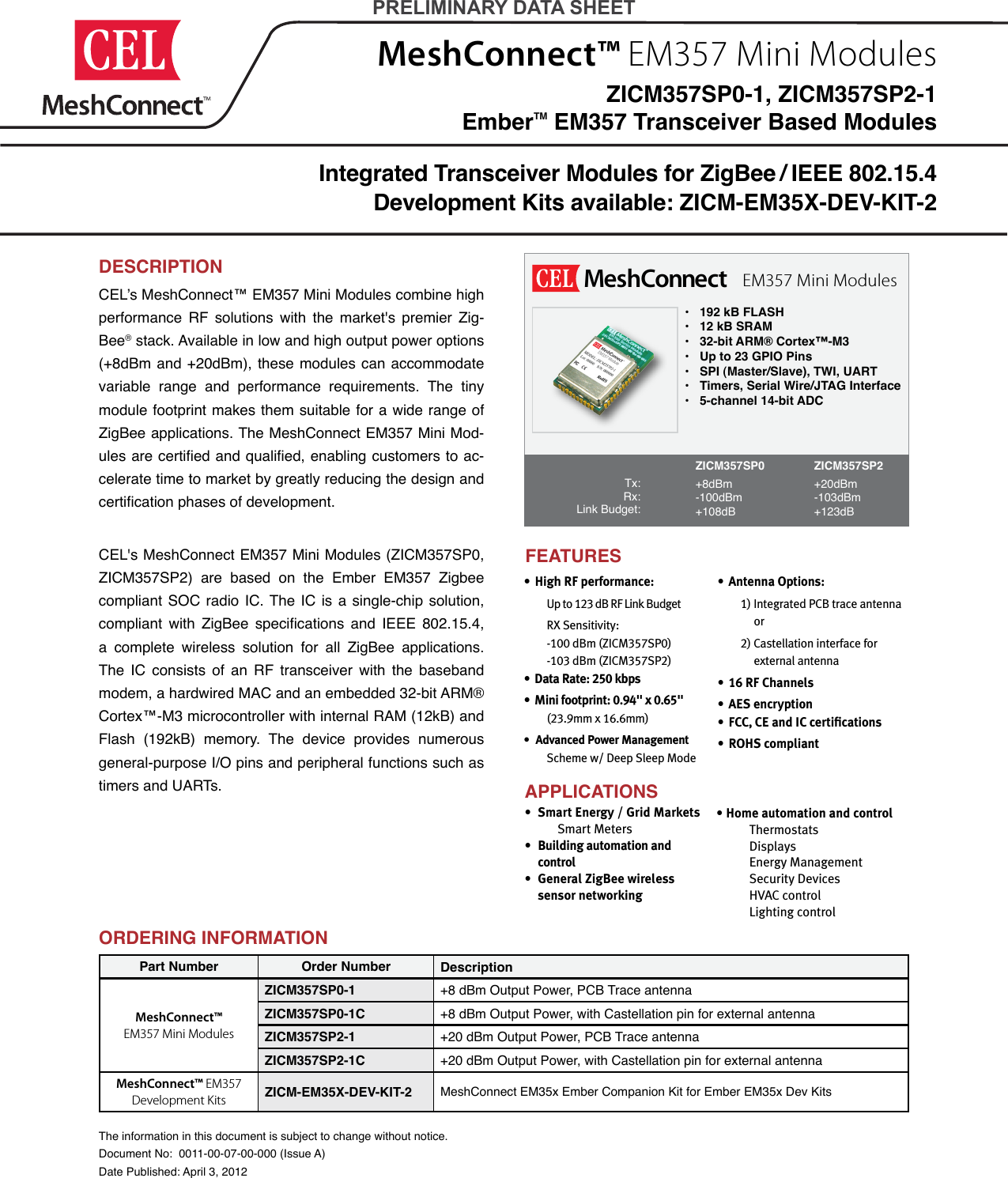
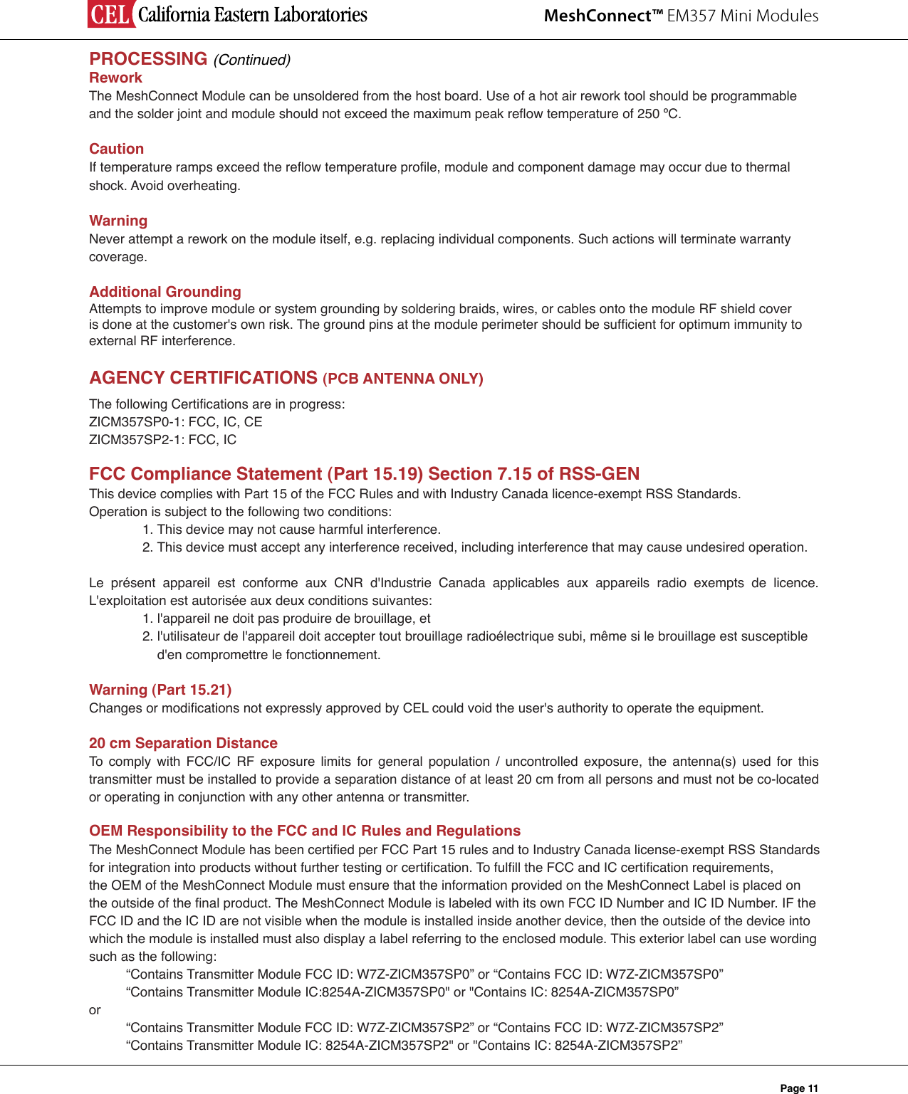
![MeshConnect™ EM357 Mini ModulesPage 2RadioMicroBalun LPFCastellationEdge ConnectorEmber EM35724MHzXTALBlock DiagramEM357 Mini Module (ZICM357SP0)RadioMicroPALNALPFTX/RXSwitchCastellationEdge ConnectorEmber EM35724MHzXTALBlock DiagramEM357 Mini Module (ZICM357SP2)DEVELOPMENT KITSCEL's Development Kits assist users in both evaluation and development. Ember Companion Kit:CEL's MeshConnect EM35x Ember Companion Kit is de-signed to work with the Ember development kits [EM35X-DEV and EM35X-DEV-IAR]. Each module in this CEL kit is soldered on a carrier board making it pin-for-pin compatible with the Ember development board.For more information regarding MeshConnect Devel-opment Kits, refer to the respective development kit user guides documents. (Available at CEL’s website )Kit Contents: MeshConnect™ EM35x Ember Companion KitDEVELOPMENT KITS ORDERING INFORMATIONPart Number Order Number Description MeshConnect™ EM35x Ember Companion Kit ZICM-EM35X-DEV-KIT-2 MeshConnect EM35x Ember Companion Kit for Ember EM35x Dev Kits](https://usermanual.wiki/California-Eastern-Laboratories/ZICM357SP0.Users-Manual/User-Guide-1691361-Page-2.png)