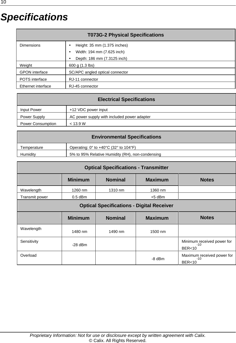
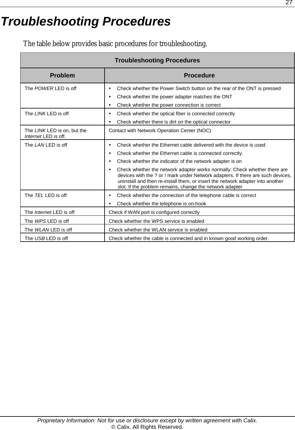
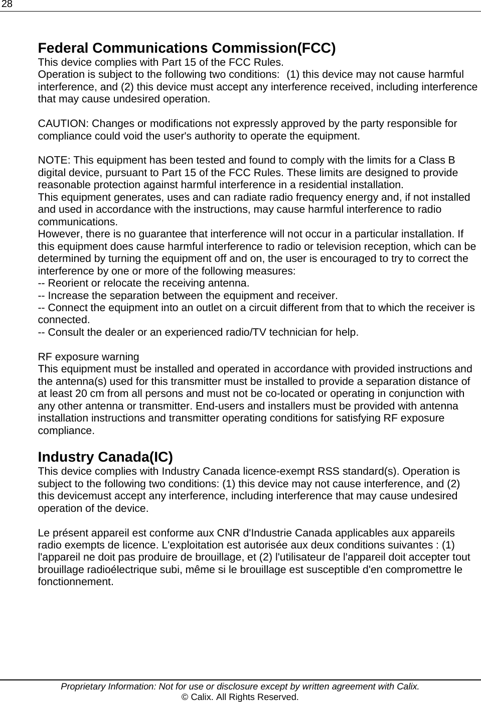
Calix T073G-2 GPON ONT User Manual

Calix Inc. GPON ONT

User Guide

   T073G-2 HGU ONT User Guide May, 2014 # 220-00718, Rev 10
  Proprietary Information: Not for use or disclosure except by written agreement with Calix. © Calix. All Rights Reserved. Contents Chapter 1  Product Description ............................................. 5Introduction .......... ............... ............... ............... ............... ................ ............... ........... 6Services ...................................................................................................................... 7 Features...................................................................................................................... 8Product Dimensions .................................................................................................. 9Specifications .......................................................................................................... 10Chapter 2  Safety................................................................... 11Electrical Safety ....................................................................................................... 12Mounting Restrictions ............................................................................................. 13Laser Safety ............................................................................................................. 14Chapter 3  Installation .......................................................... 15Get to Know the ONT .............................................................................................. 16Mounting the T073G-2 to the Wall .......................................................................... 17Connecting to the PON Network ............................................................................ 18Connecting Power ................................................................................................... 19Connecting to the AC Power Adapter ............................................................. 19Connecting Telephone (POTS) Service ................................................................. 20Connecting Ethernet Service . .................. ................. ................. .................. ........... 21Verifying the Installation ......................................................................................... 22Activating the ONT .......................................................................................... 22Verifying Services ........................................................................................... 23
4    Proprietary Information: Not for use or disclosure except by written agreement with Calix. © Calix. All Rights Reserved. Chapter 4  Troubleshooting ................................................. 25ONT Status LED ....................................................................................................... 26Troubleshooting Procedures ..... .................. ................. .................. ................. ....... 27
  Proprietary Information: Not for use or disclosure except by written agreement with Calix. © Calix. All Rights Reserved. Chapter 1 Product Description
6    Proprietary Information: Not for use or disclosure except by written agreement with Calix. © Calix. All Rights Reserved. Introduction The T073G-2 Optical Network Terminal (ONT) is an ITU-T G.984 compliant device that receives voice, data, and video traffic in the form of optical signals from the service providers Passive Optical Network (PON) and transmits it to the desired format at residential or business premises. Upstream traffic is likewise transmitted to the PON network through the fiber optic cable. A single optical fiber carries both upstream and downstream traffic.
 7  Proprietary Information: Not for use or disclosure except by written agreement with Calix. © Calix. All Rights Reserved. Services The T073G-2 is equipped with an ITU-T G.984 compliant 2.5 Gbps Downstream and 1.25 Gbps Upstream interface, and the following service ports: y Four 10/100/1000 Base-T Gigabit Ethernet Ports for High Speed Internet (HSI) Access and IPTV/VOD Services y Two POTS (VoIP) Service Ports for Voice Services y Integrated IEEE 802.11b/g/n Wireless (Wi-Fi) y One USB Host Port y Layer-2 Bridging y Home Gateway Functionality with Layer-3 Routing y Wi-Fi Protected Set-up (WPS)
8    Proprietary Information: Not for use or disclosure except by written agreement with Calix. © Calix. All Rights Reserved. Features The ONT incorporates the following features: y Single fiber GPON interface with 1244 Mbps upstream and 2488 Mbps downstream data rates y Advanced data features such as VLAN tag manipulation, classification, and filtering y Traffic classification and QoS capability y SIP-based Analog Telephone Adapter (ATA) function, which provides the different classification services, and supports caller display, call waiting, call transfer, and call forwarding y 5 REN per line y Multiple voice Codec y Rich set of LED indications for alarming and maintenance y Built-in capability for remote management such as supervision, monitoring, and maintenance y Desktop or Wall-Mounting option
 9  Proprietary Information: Not for use or disclosure except by written agreement with Calix. © Calix. All Rights Reserved. Product Dimensions The T073G-2 HGU ONT can be mounted on a tabletop or wall-mounted.
10    Proprietary Information: Not for use or disclosure except by written agreement with Calix. © Calix. All Rights Reserved. Specifications T073G-2 Physical Specifications Dimensions  y  Height: 35 mm (1.375 inches) y  Width: 194 mm (7.625 inch) y  Depth: 186 mm (7.3125 inch) Weight  600 g (1.3 lbs) GPON interface  SC/APC angled optical connector POTS interface  RJ-11 connector Ethernet interface  RJ-45 connector  Electrical Specifications Input Power  +12 VDC power input Power Supply  AC power supply with included power adapter Power Consumption  < 13.9 W  Environmental Specifications Temperature  Operating: 0° to +40°C (32° to 104°F) Humidity  5% to 95% Relative Humidity (RH), non-condensing  Optical Specifications - Transmitter  Minimum  Nominal  Maximum  Notes Wavelength  1260 nm  1310 nm  1360 nm    Transmit power  0.5 dBm     +5 dBm    Optical Specifications - Digital Receiver  Minimum  Nominal  Maximum  Notes Wavelength  1480 nm  1490 nm  1500 nm    Sensitivity  -28 dBm        Minimum received power for BER<10-10 Overload        -8 dBm  Maximum received power for BER<10-10
  Proprietary Information: Not for use or disclosure except by written agreement with Calix. © Calix. All Rights Reserved. Chapter 2 Safety Read and follow all warning notices and instructions marked on the product or included in its packaging, and observe all safety instructions listed in this guide while handling any ONT.
12    Proprietary Information: Not for use or disclosure except by written agreement with Calix. © Calix. All Rights Reserved. Electrical Safety y Always use caution when handling live electrical connections. y Do not install electrical equipment in wet or damp conditions. y Ensure that the power source for the system is adequately rated to ensure safe operation and that it provides current overload protection. y Do not allow anything to rest on the power cable, and do not place this product where people will stand or walk on the power cable. y To avoid electric shock caused by over-voltage from the Public Switched Telephone Network (PSTN), DO NOT connect the POTS port on this unit directly to any external PSTN line. y This unit must only be used with the certified power adapter model inside the package that complies with the requirement of a limited power source.
 13  Proprietary Information: Not for use or disclosure except by written agreement with Calix. © Calix. All Rights Reserved. Mounting Restrictions Follow the mounting restrictions below to ensure the ONT functions properly: y Do not stack ONTs or stack ONTs on top of other equipment. y Ensure there is a minimum of 100 mm (4") clearance directly above the top cover of the unit. y Ensure there is a minimum of 50 mm (2") clearance next to the side vent of the unit. y Ensure there are no external heat sources directly above or below the unit.
14    Proprietary Information: Not for use or disclosure except by written agreement with Calix. © Calix. All Rights Reserved. Laser Safety  CAUTION! Use of controls or adjustments, or performance of procedures other than those specified herein may result in hazardous laser radiation exposure.Invisible laser radiation may be emitted from the ends of un-terminated fiber cables or connectors. Never look directly into an un-terminated cable or connector.  Note: This ONT uses a Class 1 laser device.   DANGER! Personnel handling fiber optic cables must be trained for laser safety.   CAUTION! Do not bend the fiber optic cable to a diameter smaller than 7.5 cm (3 inches). Doing so may damage the fiber or prevent the signal from passing through properly.
  Proprietary Information: Not for use or disclosure except by written agreement with Calix. © Calix. All Rights Reserved. Chapter 3 Installation Note: For additional hardware installation information, refer to the T07xG HGU ONT Installation guide.
16    Proprietary Information: Not for use or disclosure except by written agreement with Calix. © Calix. All Rights Reserved. Get to Know the ONT The figures below provide a physical overview of the ONT.
 17  Proprietary Information: Not for use or disclosure except by written agreement with Calix. © Calix. All Rights Reserved. Mounting the T073G-2 to the Wall The ONT is mounted to the wall using two or three screws (not included) and the appropriate mounting slots on the unit.    Bracket mounting: Horizontal direction  Bracket mounting: Vertical direction
18    Proprietary Information: Not for use or disclosure except by written agreement with Calix. © Calix. All Rights Reserved. Connecting to the PON Network 1.  Locate a safe and accessible site for installation. 2.  Remove the dust covers from the SC/APC optical connector. Clean the connectors if necessary.  3.  Plug in the fiber connector to connect the ONT to the network.
 19  Proprietary Information: Not for use or disclosure except by written agreement with Calix. © Calix. All Rights Reserved. Connecting Power The T073G-2 is powered by an AC power adapter shipped with the unit.  Connecting to the AC Power Adapter  WARNING! Do not use any other power supply adapter except the one that accompanies the units. Use of other adapters could result in damage to the unit. To prevent electrical shock, do not open the cover.  To connect the power adapter cable to the ONT 1.  Plug the circular 2-pin 12 VDC power connector of the power adapter to the ONT power port. 2.  Plug the input of the power adapter into a live 120 VAC outlet. 3.  Press the Power Switch on the back of the ONT. 4.  Verify that the POWER LED on the ONT is lit (green) indicating that local power is on and voltage is within required limits.
20    Proprietary Information: Not for use or disclosure except by written agreement with Calix. © Calix. All Rights Reserved. Connecting Telephone (POTS) Service 1.  Locate the premises telephone wire pair. 2.  If the wire pair is not terminated, follow local best practices to attach an RJ-11 connector. 3.  Plug the wire pair with the RJ-11 connector into one of the ONT RJ-11 phone jacks. 4.  Repeat step 2-3 as needed to connect a second phone line as required.  POTS RJ-11 Connector Wiring Pattern Pin  Signal  Pin  Signal 1 Unused 3  Tip 2 Ring 4 Unused   WARNING! Make sure the wire pair connected is from/to the telephone. Using the wire pair from/to the PSTN network incorrectly may cause damage to user and the device.
 21  Proprietary Information: Not for use or disclosure except by written agreement with Calix. © Calix. All Rights Reserved. Connecting Ethernet Service 1.  Locate the premises CAT5 or better Ethernet cable. 2.  If the cable is not terminated, follow local best practices to attach an RJ-45 connector. 3.  Plug the Ethernet cable into the ONT RJ-45 Ethernet port. 4.  Repeat step 2-3 as needed to connect additional Ethernet cables. The table below details the specific pin-out information for the RJ-45 connector at the ONT.  Ethernet RJ-45 Connector Wiring Pattern Pin  Color  Signal  Pin  Color  Signal 1 Orange/White TX_D1+ 5  Blue/White BI_D3- 2 Orange TX_D1- 6  Green RX_D2- 3 Green/White RX_D2+ 7  Brown/White BI_D4+ 4 Blue BI_D3+ 8 Brown BI_D4-
22    Proprietary Information: Not for use or disclosure except by written agreement with Calix. © Calix. All Rights Reserved. Verifying the Installation Check the LED states to verify ONT status. Services are not available until the ONT is ranged and provisioned in the PON network. If services must be verified at the time of installation, refer to Verifying Services for additional instructions.  Activating the ONT Once the ONT installation is complete, follow the procedure below for verifying ONT status. The figures below displays the typical LED status after the ONT boot sequence is complete. ONT Has Not Been Provisioned  ONT Has Been Provisioned   To verify proper operation y Verify that the POWER LED light is green, indicating that the local power level is within proper limits. y Verify that the AUTH LED light is green, indicating that the ONT is operating normally. The ONT is placed into service remotely through the OLT. Services to the ONT are likewise provisioned and turned up remotely through the PON network. y If the AUTH LED is blinking, indicating that the ONT is communicating with the PON network, no further activation is necessary and you can proceed to Verifying Services. y If the AUTH LED does not light green, contact the Network Operation Center (NOC) to activate the line. You may be required to provide or confirm the following information about the ONT:   y Vendor y Model number y Serial number
 23  Proprietary Information: Not for use or disclosure except by written agreement with Calix. © Calix. All Rights Reserved. Once the ONT has been activated in the network, and the AUTH LED illuminates green, proceed to Verifying Services.  Verifying Services Follow local best practices to connect to each active service port in the ONT to confirm proper service activation. y Connect to each active phone jack to verify telephone numbers and services. Verify that the TEL1 or TEL2 LED flashes green when a line is off-hook. y If Ethernet service is included in this installation, confirm that data is being received and transmitted normally. The LAN1/LAN2/LAN3/LAN4 LED should flash as data packets are being transmitted. y If WLAN service is included in this installation, confirm that data is being received and transmitted on the WLAN interface. Verify the WLAN LED illuminates green when the WLAN is connected.
  Proprietary Information: Not for use or disclosure except by written agreement with Calix. © Calix. All Rights Reserved. Chapter 4 Troubleshooting
26    Proprietary Information: Not for use or disclosure except by written agreement with Calix. © Calix. All Rights Reserved. ONT Status LED The ONT status LEDs assist with installation and maintenance procedures. These LEDs are described below. T073G-2 HGU ONT LEDs   T073G-2 LED Field Descriptions LED  Color  Status  Indication POWER  Green  Solid  ONT is operating on AC power from the adapter Fast Blink  ONT is booting up LINK  Green  Solid  Optical link is OK Off  Optical link is NOT OK AUTH Green Solid  ONU is authorized Blink  ONU is registering Off  ONU is NOT authorized LAN1/4 Green Solid  LAN port connected, but no data transmission. Blink  LAN port has data transmission Off  LAN port is not connected to terminal device or system power is off TEL1/2 Green Solid  Already register to soft-switch, but no service flow and the line is on-hookBlink  There is service flow on this port or the telephone is off-hook Off  System power is off, or is not registered to soft-switch Internet Green Solid  Indicate PPPoE or DHCP sign up completed successfully. Internet is connected Blink  Indicate to be getting IP with PPPoE or DHCP Off  Indicate WAN is not configured WPS Green Solid Register successfully Yellow  Blink  Register is in progress Red  Blink  Session Overlap Detected or WPS Error Green  Off  WPS function is not enable, or system power is off WLAN Green Solid  Wireless Interface enable Blink  Data transmitting at wireless interface Off  Wireless interface disable, or system power off USB Green Solid  USB interface connected and working on host mode, but there is no data transmission Blink  USB interface has data transmission Off  USB interface has no connection, or system power is off
 27  Proprietary Information: Not for use or disclosure except by written agreement with Calix. © Calix. All Rights Reserved. Troubleshooting Procedures The table below provides basic procedures for troubleshooting.  Troubleshooting Procedures Problem  Procedure The POWER LED is off  y  Check whether the Power Switch button on the rear of the ONT is pressed y  Check whether the power adapter matches the ONT y  Check whether the power connection is correct The LINK LED is off  y  Check whether the optical fiber is connected correctly y  Check whether there is dirt on the optical connector The LINK LED is on, but the Internet LED is off.  Contact with Network Operation Center (NOC) The LAN LED is off  y  Check whether the Ethernet cable delivered with the device is used. y  Check whether the Ethernet cable is connected correctly. y  Check whether the indicator of the network adapter is on y  Check whether the network adapter works normally: Check whether there are devices with the ? or ! mark under Network adapters. If there are such devices, uninstall and then re-install them, or insert the network adapter into another slot. If the problem remains, change the network adapter The TEL LED is off  y  Check whether the connection of the telephone cable is correct y  Check whether the telephone is on-hook The Internet LED is off  Check if WAN port is configured correctly The WPS LED is off  Check whether the WPS service is enabled The WLAN LED is off  Check whether the WLAN service is enabled The USB LED is off  Check whether the cable is connected and in known good working order.
28    Proprietary Information: Not for use or disclosure except by written agreement with Calix. © Calix. All Rights Reserved.  Federal Communications Commission(FCC) This device complies with Part 15 of the FCC Rules. Operation is subject to the following two conditions: (1) this device may not cause harmful interference, and (2) this device must accept any interference received, including interference that may cause undesired operation.  CAUTION: Changes or modifications not expressly approved by the party responsible for compliance could void the user's authority to operate the equipment.  NOTE: This equipment has been tested and found to comply with the limits for a Class B digital device, pursuant to Part 15 of the FCC Rules. These limits are designed to provide reasonable protection against harmful interference in a residential installation. This equipment generates, uses and can radiate radio frequency energy and, if not installed and used in accordance with the instructions, may cause harmful interference to radio communications. However, there is no guarantee that interference will not occur in a particular installation. If this equipment does cause harmful interference to radio or television reception, which can be determined by turning the equipment off and on, the user is encouraged to try to correct the interference by one or more of the following measures: -- Reorient or relocate the receiving antenna. -- Increase the separation between the equipment and receiver. -- Connect the equipment into an outlet on a circuit different from that to which the receiver is connected. -- Consult the dealer or an experienced radio/TV technician for help.  RF exposure warning   This equipment must be installed and operated in accordance with provided instructions and the antenna(s) used for this transmitter must be installed to provide a separation distance of at least 20 cm from all persons and must not be co-located or operating in conjunction with any other antenna or transmitter. End-users and installers must be provided with antenna installation instructions and transmitter operating conditions for satisfying RF exposure compliance.  Industry Canada(IC) This device complies with Industry Canada licence-exempt RSS standard(s). Operation is subject to the following two conditions: (1) this device may not cause interference, and (2) this devicemust accept any interference, including interference that may cause undesired operation of the device.    Le présent appareil est conforme aux CNR d'Industrie Canada applicables aux appareils radio exempts de licence. L'exploitation est autorisée aux deux conditions suivantes : (1) l'appareil ne doit pas produire de brouillage, et (2) l'utilisateur de l'appareil doit accepter tout brouillage radioélectrique subi, même si le brouillage est susceptible d'en compromettre le fonctionnement.

Navigation menu