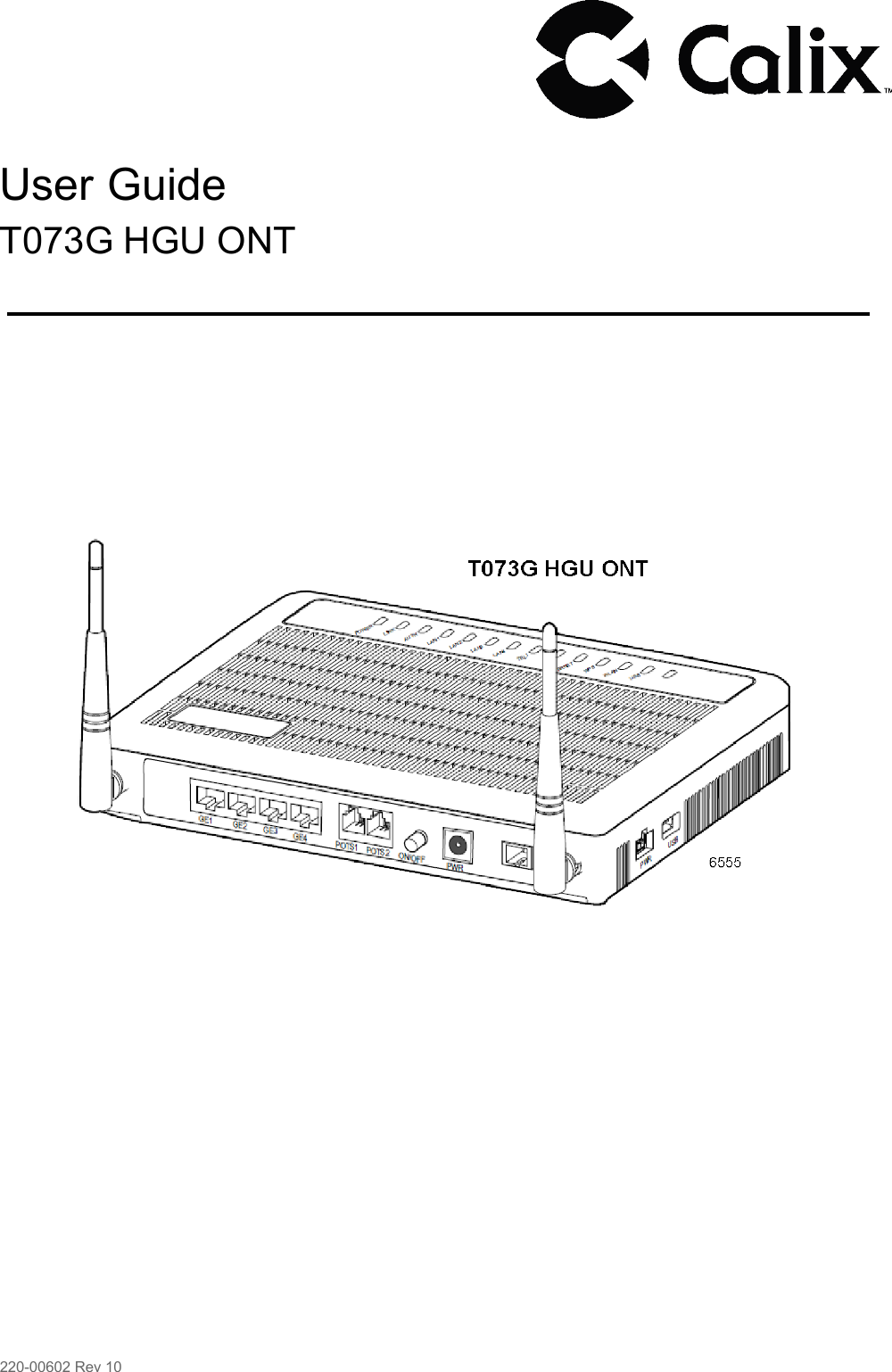
Calix T077GT073G GPON ONT User Manual T073G HGU ONT User Guide

Calix Inc. GPON ONT T073G HGU ONT User Guide

Contents

(T077G&TO73G) T073G_User Guide 2014.1.08

      User Guide  T073G HGU ONT                                                            220-00602 Rev 10
     Copyright  © Calix. All rights reserved. No part of this document may be reproduced in any form without the written permission of the copyright owner.  Disclaimer  The contents of this document are subject to revision without notice due to continued progress in methodology, design, and manufacturing. Calix shall have no liability for any error or damage of any kind resulting from the use of this document.   Trademark List  Calix Calix is the trademark or registered trademark of Calix. All other trademarks mentioned herein are the property of their respective owners.                                           220-00602 R10   |   October, 2013
Contents        Contents      1  Product Description  1 1.1 Introduction  1 1.2 Services  1 1.3 Features  1 1.4 Specifications  2  2  Safety  4 2.1 Electrical Safety  4 2.2 Laser Safety  4  3  Installation  6 3.1 Get to Know the ONT  6 3.2 Connecting to the PON Network  6 3.3 Connecting Power  7 3.4 Connecting Telephone (POTS) Service  9 3.5 Connecting Ethernet Service  9 3.6 Verifying the Installation 10  4  Troubleshooting 12 4.1 ONT Status LEDs 12 4.2 Troubleshooting Procedures 13                             220-00602 R10  |   October, 2013
User Guide                                                                           220-00602 R10   |   October, 2013
Product Description        1  Product Description   1.1  Introduction  The T073G Optical Network Terminal (ONT) is an ITU-T G.984 compliant device that receives voice, data, and video traffic in the form of optical signal from the service provider Passive Optical Network (PON) and transmitted it to the desired format at residential or business premises.  Upstream traffic is likewise transmitted to the PON network through the fiber optic cable. A single optical fiber carries both upstream and downstream traffic.   1.2  Services  T073G is equipped with ITU-T G.984 compliant 2.5 Gbps Downstream and 1.25 Gbps Upstream interface, and the following service ports:  • Four 10/100/1000 Base-T Gigabit Ethernet ports for high speed internet access and IPTV/VOD services  • Two POTS (VoIP) service ports for voice services  • Integrated IEEE 802.11b/g/n wireless  • One USB host port   1.3  Features  The ONT incorporates the following features:  • Single fiber GPON interface with 1244 Mbps upstream and 2488 Mbps downstream data rates  • Advanced data features such as VLAN tag manipulation, classification, and filtering  • Traffic classification and QoS capability  • SIP-based Analog Telephone Adapter (ATA) function, which provides the different classification services, and supports caller display, call waiting, call transfer, and call forwarding.  •  5 REN per line  • Multiple voice Codec  • Rich set of LED indications for alarming and maintenance  • Built-in capability for remote management like supervision, monitoring, and maintenance    220-00602 R10   |   October, 2013 1
User Guide    1.4  Specifications  Table 1 lists the physical specification. Table 2 lists the electrical specification. Table 3 lists the environmental specification. Table 4 lists the optical specification.  Table 1  Physical Specifications  Dimensions • Height: 47 mm (1.85 inch)  • Width: 229 mm (9 inch)  • Depth: 174 mm (6.85 inch) Weight 640 g GPON interface SC/APC angled optical connector  POTS interface RJ-11 connector  Ethernet interface RJ-45 connector  Table 2  Electrical Specification  Input Power +12V DC power input  Power Supply AC power supply with included power adapter  Power Consumption <14.4 W  Table 3  Environmental Specification  Temperature Operating:  0°         C to +40°         C (32° to 104° F)  Humidity 5% to 95% Relative Humidity (RH), non-condensing  Table 4  Optical Specification  Minimum Nominal Maximum Notes  Transmitter  Wavelength 1260 nm 1310 nm 1360 nm  Transmit power  Digital receiver  0.5 dBm +5 dBm  Wavelength 1480 nm 1490 nm 1500 nm                 2  220-00602 R10   |   October, 2013
Product Description         Minimum Nominal Maximum Notes  Sensitivity  -27 dBm                                                             Minimum received power for BER<10-10  Overload  -8 dBm Maximum received power for BER<10-10                                                       220-00602 R10  |   October, 2013 3
User Guide        2  Safety     Read and follow all warning notices and instructions marked on the product or included in its packaging, and observe all safety instructions listed in this guide while handling any ONT.   2.1  Electrical Safety  •     Always use caution when handling live electrical connections.  •     Do not install electrical equipment in wet or damp conditions.  • Ensure that the power source for the system is adequately rated to assure safe operation and provides current overload protection.  • Do not allow anything to rest on the power cable, and do not place this product where people will stand or walk on the power cable.  •     To avoid electric shock of user which caused by over-voltage from PSTN. DO NOT connect the POTS port on this unit directly to external PSTN line.  • This unit can only be used with the certified adaptor model inside the package, which complies with the requirement of limited power source.   2.2  Laser Safety    Caution!   Use of controls or adjustments, or performance of procedures other than those specified herein may result in hazardous laser radiation exposure.  Invisible laser radiation may be emitted from the ends of un-terminated fiber cables or connectors. Never look directly into an un-terminated cable or connector.    Note: This ONT uses a class 1 laser device.            4  220-00602 R10   |   October, 2013
Safety           Danger!   Personnel handling fiber optic cables must be trained for laser safety.      Caution!   Do not bend the fiber optic cable to a diameter smaller than 7.5 cm (3 inches). Doing so may damage the fiber or prevent the signal from passing through properly.                                                220-00602 R10   |   October, 2013 5
User Guide        3  Installation     3.1  Get to Know the ONT  The figures below show the overview of the ONT.                    Ethernet ports  POTS ports    Power switch     DC power connector USB connector  UPS connector  G102382A  Figure 1  T073G Back and Right-Side Overview         WPS  RESET WLAN       Figure 2  T073G Left-Side Overview   3.2  Connecting to the PON Network  1. Locate a safe and accessible site for installation. G102296A     6  220-00602 R10   |   October, 2013
Installation         2. Remove the dust covers from the SC/APC optical connector. Clean the connectors if necessary.                   G102342A   3. Plug in the fiber connector to connect the ONT to the network.                   G102343A   3.3  Connecting Power  The T073G can be powered by the AC power adapter or by an UPS power. This section describes how to power the ONT by both.  Note: Do not connect the enclosed power supply adapter and an external UPS simultaneously, as this might cause unwanted behavior.              220-00602 R10   |   October, 2013 7
User Guide         3.3.1 Connecting to the AC Power Adapter    Warning!   Do not use any other power supply adapter except the one that accompanies the units. Use of other adapters could result in damage to the unit. To prevent electrical shock, please do not open the cover.    To connect the power cable to the ONT, do the following:  1. Plug the circle two pin 12V DC power connector of power adapter to ONT power port.  2. Plug the input of power adapter into a live AC outlet.  3. Push the Power Switch button on the back of the ONT.  4. Verify that the POWER LED on the ONT is lit green indicating that local power is on and voltage is good.  3.3.2 Connecting to an External UPS  NOTE:  UPS power cord is sold separately. It is not included with this package. Please contact Calix customer support for information.  8  5          4  1 G102409A  Figure 3  UPS PIN Numbering  Table 5  UPS PIN Signal Description  PIN Color Signal Description  1  Red +12 V  DC 12 V DC input  2  White ON_BAT On battery 3  Blue BAT_MISSING Battery missing      8  220-00602 R10   |   October, 2013
Installation         PIN Color Signal Description  4  Green NC Unused 5  Black/Brown GND Power ground/Signal ground 6  Purple REPLACE_BAT Replace battery 7  Orange LOW_BAT Low battery  8  Yellow NC Unused    3.4  Connecting Telephone (POTS) Service  1. Locate the telephone wire pair of premise.  2. If the wire pair is not terminated, follow local practices to attach an RJ-11 connector  3. Plug the wire pair with RJ-11 connector into one of the ONT RJ-11 phone jacks  4. Repeat step 2-3 as needed to connect additional phone lines  Table 6 POTS RJ-11 Connector Wiring Pattern  Pin Signal Pin Signal 1  Unused 3  Tip  2  Ring 4  Unused    Danger!   Please make sure the wire pair connected is from/to the telephone. Using the wire pair from/to the PSTN network falsely may cause damage to user and the device.    3.5  Connecting Ethernet Service  1. Locate the Ethernet LAN cable of premise.  2. If the cable is not terminated, follow local practices to attach an RJ-45 connector.  3. Plug the Ethernet cable into the ONT RJ-45 Ethernet port  4. Repeat step 2-3 as needed to connect additional Ethernet cables.     220-00602 R10   |   October, 2013 9
User Guide         Table 7 Ethernet RJ-45 Connector Wiring Pattern  Pin Color Signal Pin Color Signal 1  Orange/White TX_D1+ 5  Blue/White BI_D3- 2  Orange TX_D1-  6  Green RX_D2- 3  Green/White RX_D2+ 7  Brown/White BI_D4+  4  Blue BI_D3+ 8  Brown BI_D4-    3.6  Verifying the Installation  Check LED states to verify ONT status. Services are not available until the ONT is ranged and provisioned in the PON network. If services must be verified at the time of installation, refer to Section 3.6.2 Verifying Services on page 11 for additional instructions.    3.6.1 Activating the ONT  Once the ONT installation is complete, follow the procedure below for verifying ONT status. Figures below shows the typical status LED display after the ONT boot sequence is complete.             Figure 4  ONT Has not Been Provisioned G102380A             Figure 5  ONT Has Already Been Provisioned G102381A   • Verify that the POWER LED light is green, indicating that local power level is good     10 220-00602 R10   |   October, 2013
Installation         • Verify that the AUTH LED light is green, indicating that the ONT is operating normally.  The ONT is placed into service remotely through the OLT. Services to the ONT are likewise provisioned and turned up remotely through the PON network.  • If the AUTH LED is blinking, indicating that the ONT is communicating with the PON network, no further activation is necessary and you can proceed to Section 3.6.2 Verifying Services on page 11 for verifying services.  • If the AUTH LED does not light green, contact the Network Operation Center (NOC) to activate the line. You may be required to provide or confirm the following information about the ONT: vendor, model number, serial number. Once the ONT has been activated in the network, and the AUTH LED is lit green, you can proceed to Section 3.6.2 Verifying Services on page 11 for verifying services.   3.6.2 Verifying Services  Follow local practices to connect to each active service port in the ONT to confirm service activation.  • Connect to each active phone jack to verify telephone numbers and services. Verify that the TEL1 or TEL2 LED lights flashing green when a line is off-hook.  • If Ethernet service is included in this installation, confirm that data is being received and transmitted normally. The LAN1 or LAN2 or LAN3 or LAN4 LED will be flashed during data transmission.  • If WLAN service is included in this installation, confirm that data is being received and transmitted on WLAN interface. Verify the WLAN LED is green when the WLAN is connected.                          220-00602 R10   |   October, 2013 11
User Guide        4  Troubleshooting     4.1  ONT Status LEDs  The ONT status LEDs assist with installation and maintenance procedures. These LEDs are described in Table 8.             Figure 6  ONT Status LEDs location  Table 8  T073G LED Description  LED Color Status Indication G102381A  POWER  Green  Solid ONT is operating from AC power  Slow Blink ONT is operating from UPS power  Fast Blink System Booting  Red Solid UPS battery low  LINK Green   AUTH Green  Solid Optical link is OK  Off Optical link is NOT OK Solid ONU is authorized Blink ONU is registering Off ONU is NOT authorized  LAN1/4    Green  Solid LAN port connected, but no data transmission.  Blink LAN port has data transmission  Off LAN port is not connected to terminal device or system power is off              12 220-00602 R10   |   October, 2013
Troubleshooting         LED Color Status Indication  TEL1/2  Green         Internet Green  Solid Already register to soft-switch, but no service flow and the line is on-hook  Blink There is service flow on this port or the telephone is off-hook  Off System power is off, or is not registered to soft-switch  Solid Indicate PPPoE or DHCP sign up completed successfully.  Internet is connected  Blink Indicate to be getting IP with PPPoE or DHCP  Off Indicate WAN is not configured  WPS  Green Solid Register successfully  Yellow Blink Register is in progress  Red Blink Session Overlap Detected or WPS Error  Green Off WPS function is not enable, or system power is off  WLAN Green      USB Green  Solid Wireless Interface enable  Blink Data transmitting at wireless interface  Off Wireless interface disable, or system power off  Solid USB interface connected and working on host mode, but there is no data transmission  Blink USB interface has data transmission  Off USB interface has no connection, or system power is off    4.2  Troubleshooting Procedures  Table 9 provides the basic procedures for troubleshooting.               220-00602 R10  |   October, 2013 13
User Guide         Table 9  Troubleshoot Procedures  Problem Procedure  The POWER LED is off • Check whether the Power Switch button on the rear of the ONT is pressed  • Check whether the power adapter matches the ONT  • Check whether the power connection is correct  The LINK LED is off • Check whether the optical fiber is connected correctly  • Check whether there is dirt on the optical connector  The LINK LED is on, but the Internet LED is off.  Contact with Network Operation Center (NOC)  The LAN LED is off • Check whether the Ethernet cable delivered with the device is used.  • Check whether the Ethernet cable is connected correctly.  • Check whether the indicator of the network adapter is on  • Check whether the network adapter works normally: Check whether there are devices with the ?  or !  mark under Network adapters.  If there are such devices, uninstall and then re-install them, or insert the network adapter into another slot. If the problem remains, change the network adapter  The TEL LED is off • Check whether the connection of the telephone cable is correct  • Check whether the telephone is on-hook The Internet LED is off Check if WAN port is configured correctly The WPS LED is off Check whether the WPS service is enabled The WLAN LED is off Check whether the WLAN service is enabled The USB LED is off Check whether the cable is normal             14 220-00602 R10   |   October, 2013
FCC statement ·This device complies with part 15 of the FCC Rules. Operation is subject to the following two conditions: (1) This device may not cause harmful interference, and (2) this device must accept any interference received, including interference that may cause undesired operation. ·This equipment has been tested and found to comply with the limits for a Class B digital device, pursuant to part 15 of the FCC Rules. ·These limits are designed to provide reasonable protection against harmful interference in a residential installation. This equipment generates, uses and can radiate radio frequency energy and, if not installed and used in accordance with the instructions, may cause harmful interference to radio communications. However, there is no guarantee that interference will not occur in a particular installation. ·If this equipment does cause harmful interference to radio or television reception, which can be determined by turning the equipment off and on, the user is encouraged to try to correct the interference by one or more of the following measures: —Reorient or relocate the receiving antenna. —Increase the separation between the equipment and receiver. —Connect the equipment into an outlet on a circuit different from that to which the receiver is connected. —Consult the dealer or an experienced radio/TV technician for help.
RF exposure warning · This equipment must be installed and operated in accordance with provided instructions and the antenna(s) used for this transmitter must be installed to provide a separation distance of at least 20 cm from all persons and must not be co-located or operating in conjunction with any other antenna or transmitter. End-users and installers must be provided with antenna installation instructions and transmitter operating conditions for satisfying RF exposure compliance.   NOTE: THE GRANTEE IS NOT RESPONSIBLE FOR ANY CHANGES OR MODIFICATIONS NOT EXPRESSLY APPROVED BY THE PARTY RESPONSIBLE FOR COMPLIANCE. SUCH MODIFICATIONS COULD VOID THE USER’S AUTHORITY TO OPERATE THE EQUIPMENT.    Statement  ·This device PA02 doesn’t support the function to modify the country code, and the channel 12 and 13 are closed in the device PA02.  

Navigation menu