Cambium Networks 25600 Wireless Ethernet Bridge User Manual PTP 400 Series User Guide
Cambium Networks Limited Wireless Ethernet Bridge PTP 400 Series User Guide
UserManual.wiki
>
Cambium Networks
>
25600 User Manual
Users Manual
Navigation menu
Upload a User Manual
Namespaces
Wiki Guide
HTML
PDF
Info
Views
User Manual
Discussion / Help
Navigation

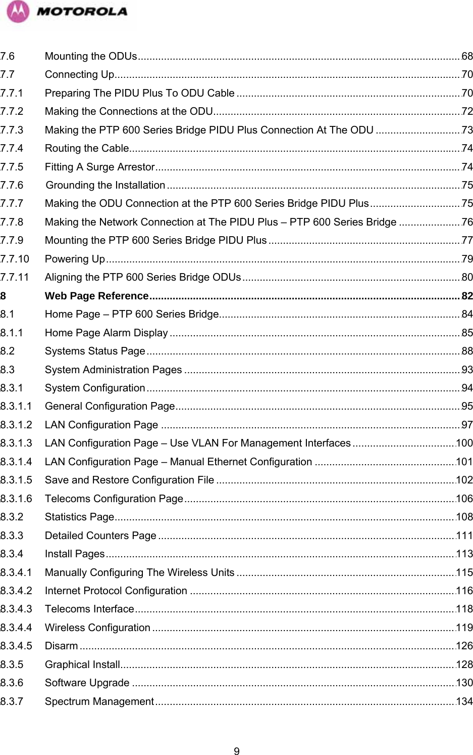


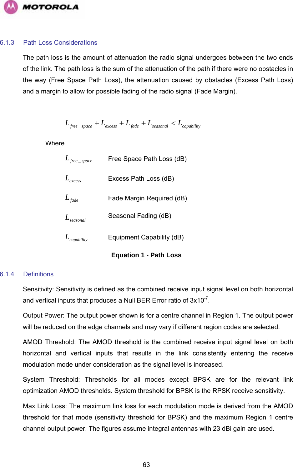
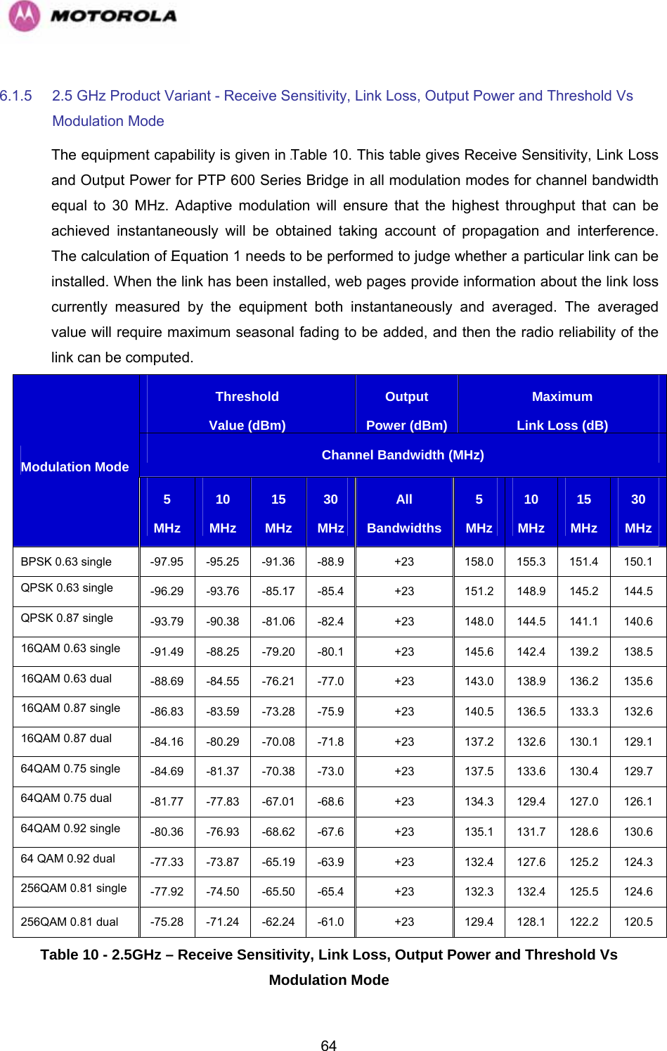
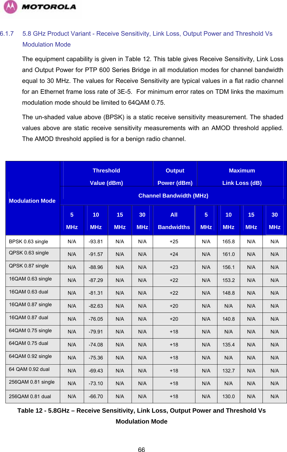
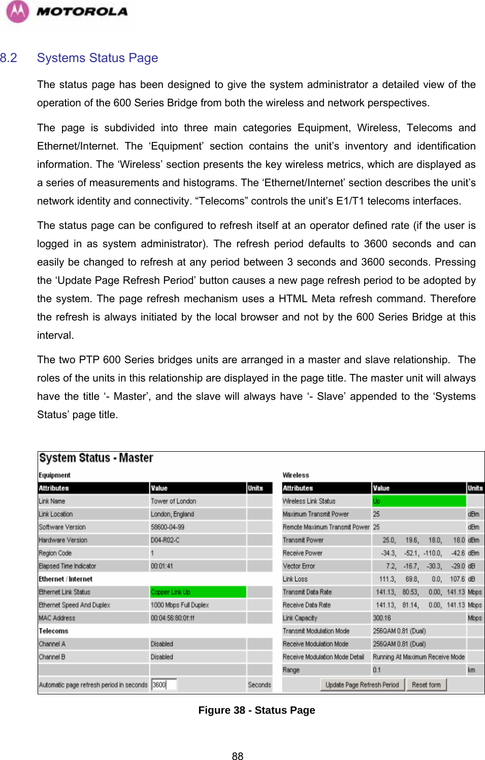
![33Alternately, the network connection to a PTP 600 Series Bridge can be made using a 1000BaseSX Fiber Optic cable connected directly to the ODU. In this case power is still provided over the 1000BaseT Ethernet connection. In the case of Fiber Optic cable failure the PTP 600 Series Bridge will automatically fall back to the copper Ethernet connection (provided the cable length <=100m [330 ft]). “PTP 600 Series Optical Interface Upgrade Kits” can be obtained from your distributor, reseller or system integrator. Power is fed into the PTP 600 Series Bridge PIDU Plus from the mains via a standard “figure of eight” mains plug. Connection between the ODU and PIDU Plus is made using standard CAT5e outdoor UV resistant cable. Connection between the PIDU Plus and the Network Equipment is made using standard CAT5e cable. 3.3.1 The Outdoor Unit (ODU) The ODU (966HFigure 3) is a self-contained unit. It houses both radio and networking electronics. The ODU for the PTP 600 Series Bridge should only be deployed using the supplied PTP 600 Series Bridge PIDU Plus. Figure 3 – PTP 600 Series Bridge Outdoor Unit (ODU)](https://usermanual.wiki/Cambium-Networks/25600/User-Guide-821733-Page-35.png)
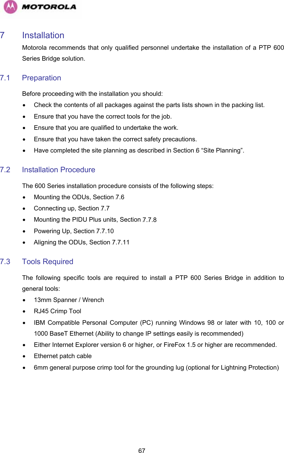
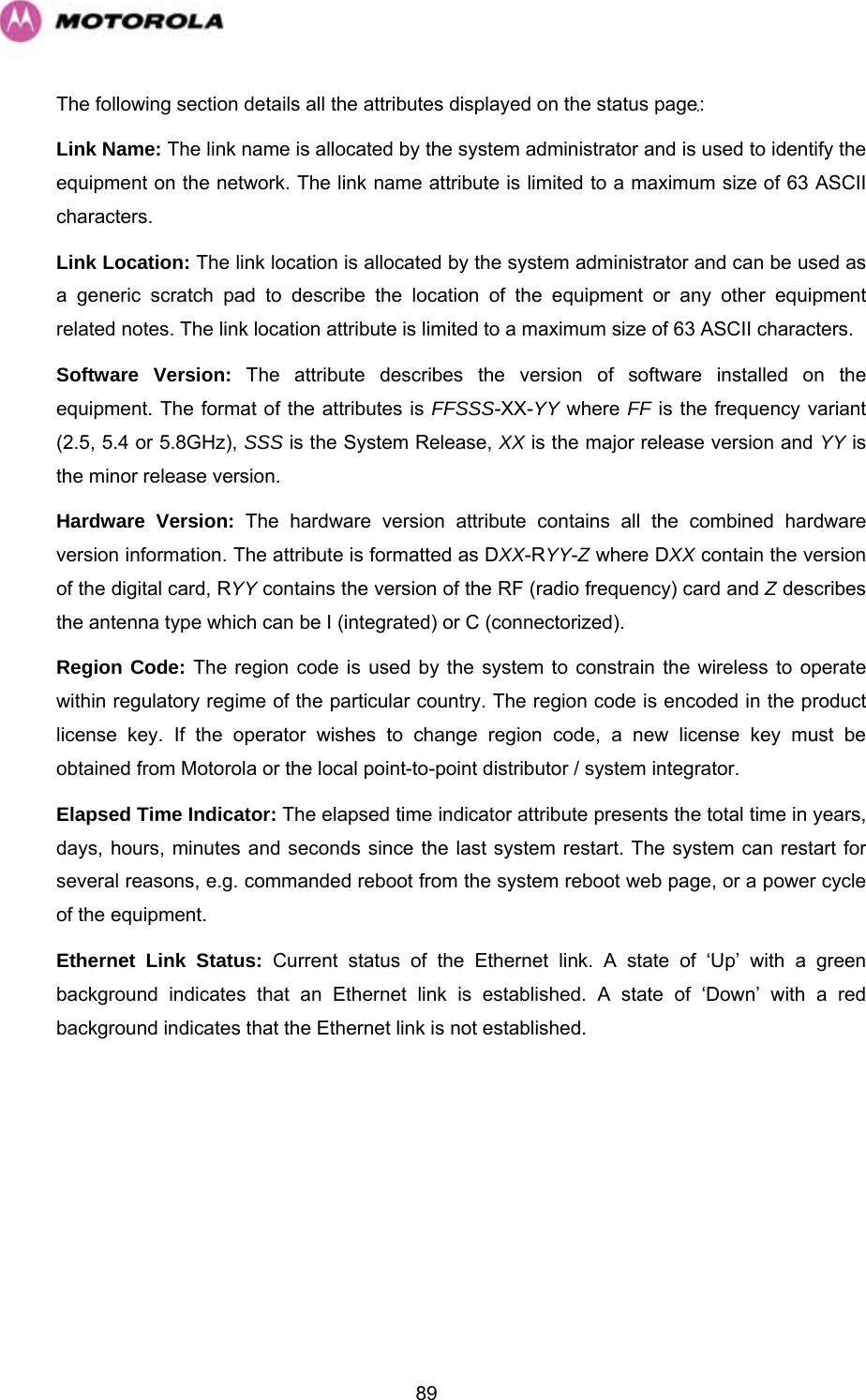
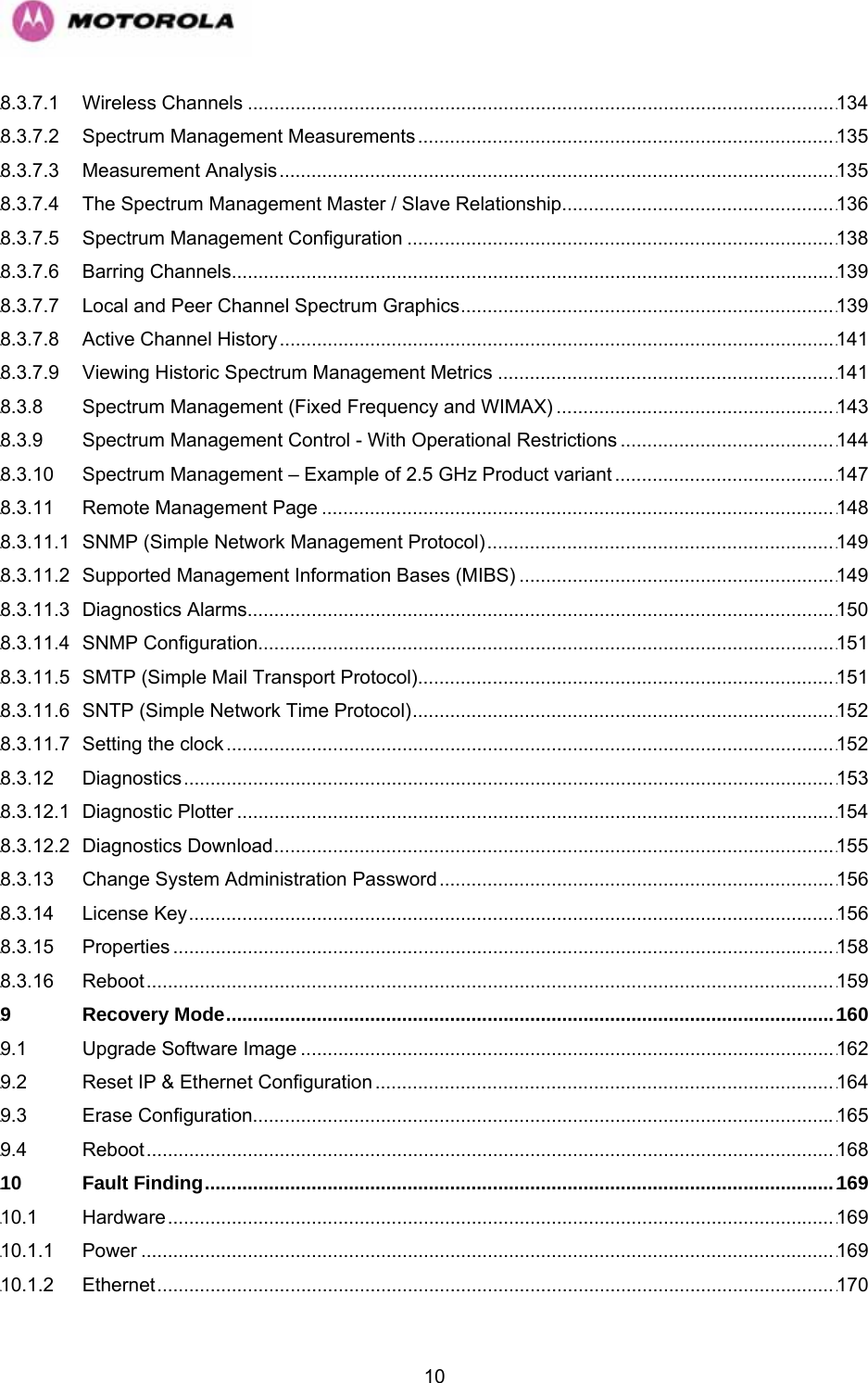
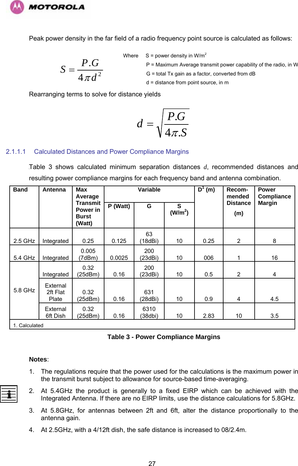
![626 Site Planning 6.1 Site Selection Criteria The following are guidelines for selecting the installation location of the ODU and PDU Plus for a PTP 600 Series Bridge. 6.1.1 ODU Site Selection When selecting a site for the ODU the following should be taken into consideration: • It is not possible for people to stand or walk inadvertently in front of the antenna • Height and location to achieve the best radio path • Height in relation to other objects with regard to lightning strikes • Protection from the weather • Aesthetics and planning permission issues • Distance from the ODU and connected Network equipment (Maximum cable run from the ODU to the connected equipment is 100m [330 ft]) • Distance from the PIDU Plus to the ODU (Maximum cable run from the PIDU Plus to the ODU is 100m [330 ft] when using the 1000BaseT interface) 6.1.2 PTP 600 Series Bridge PIDU Plus Site Selection When selecting a site for the PIDU Plus the following should be taken into consideration: • Availability of a mains electricity supply • Accessibility for viewing status indicators and pressing reset switch (See Section 1018H3.3.2 and Section 1019H10)](https://usermanual.wiki/Cambium-Networks/25600/User-Guide-821733-Page-64.png)