Cambium Networks 25600 Wireless Ethernet Bridge User Manual PTP 400 Series User Guide
Cambium Networks Limited Wireless Ethernet Bridge PTP 400 Series User Guide
Users Manual

PTP 600 Series
User Guide
MOTOROLA POINT-TO-POINT WIRELESS SOLUTIONS

1
MOTOROLA, Inc.
Point-to-Point Wireless Bridges – PTP 600 Series
Software Release PTP 600-05-00
System User Manual
July 26th, 2007
Ref: PHN-0896-01.08
Copyright Information
This document is the confidential property of Motorola, Inc. and without its prior written consent may
not be copied or released to third parties.
MOTOROLA, the stylized M Logo and all other trademarks indicated as such herein are trademarks
of Motorola, Inc. ®
Reg. U.S. Pat & Tm. Office. PTP 600 is a trademark of Motorola, Inc. All other
product or service names are the property of their respective owners.
© 2007 Motorola, Inc. All rights reserved.
http://www.motorola.com/ptp
Compliance
General
Changes or modifications not expressly approved by Motorola could void the user’s authority to
operate the system.
NOTE: This system has achieved Type Approval in various countries around the world. This means
that the system has been tested against various local technical regulations and found to comply. The
frequency bands in which the system operates is may be ‘unlicensed’ and, in these bands, the system
can be used provided it does not cause interference. Further, it is not guaranteed protection against
interference from other products and installations.

2
The system has basically been shown to comply with the limits for emitted spurious radiation for a
Class B digital device1, pursuant to Part 15 of the FCC Rules in the USA as well as comparable
regulations in other countries. These limits have been designed to provide reasonable protection
against harmful interference in a residential installation. This equipment generates uses and can
radiate radio frequency energy and, if not installed and used in accordance with the instructions, may
cause harmful interference to radio communications. However, there is no guarantee that interference
will not occur in a particular installation.
If this equipment does cause harmful interference to radio or television reception, which can be
determined by turning the equipment off and on, the user is encouraged to try to correct the
interference by one or more of the following measures:
• Reorient or relocate the Outdoor Unit (ODU).
• Increase the separation between the equipment and ODU.
• Connect the equipment into a power outlet on a circuit different from that to which the
receiver is connected.
• Consult your installer or supplier for help.
Deployment and Operation
The Radio Regulations of various countries’ limits constrain the operation of radio products generally.
In particular the local regulator may limit the amount of conducted or radiated transmitter power and
may require registration of the radio link.
The power transmitted by the PTP 600 Series Bridge is controlled by the use of Region-specific
License Keys.
The following examples show how the regulatory limits apply in some specific countries at the current
time. Operators should note that regulations are subject to change.
Contact your supplier/installer to ensure that your product is set for the correct License Key for your
Country/Region and to ensure that you have fulfilled all the local regulatory requirements, especially if
you are intending to use a link with external antennas. Footnotes to the table below indicate countries
where registration of the link is currently mandatory.
1 Class B Digital Device, A digital device that is marketed for use in a residential environment notwithstanding use in
commercial, business and industrial environments.

3
Regulations applicable to 2.5GHz PTP 600 Series Bridge variant
Examples of Regulatory Limits at 2.5GHz
FCC
Under FCC Regulations, operation of this product
is only allowed with a License Key for Region 16
which ensures that the product will meet the
requirements of FCC part 27.
Note: Spectrum in this band (2499MHz to
2690MHz) is allocated on a Licensed basis in USA.
General Notice Applicable to Europe
N/A.

4
Regulations applicable to 5.4GHz PTP 600 Series Bridge variant
Examples of Regulatory Limits at 5.4GHz
Non-FCC and Non-ETSI2
Equipment can be operated in any mode, best
results will be obtained using Region 8 settings
(Region 7 if DFS is required)
FCC
Under FCC Regulations, operation of this product
is only allowed with a License Key for Region 12
(30dBm or 1W EIRP with Radar Detection)
Canada
Under IC Regulations, operation of this product is
only allowed with a License Key for Region 13
(30dBm or 1W EIRP with Radar Detection and
barring of the band 5600-5650MHz)
ETSI
Under ETSI Regulations, operation of this product
is only allowed with a License Key for Region 12
(30dBm or 1W EIRP with Radar Detection)
General Notice Applicable to Europe
This equipment complies with the essential requirements for the
EU R&E Directive 1999/5/EC.
2 Note: In regions other than EU/USA, specific local regulations may apply. It is the responsibility of the installer/user to check
that the equipment as deployed meets local regulatory requirements.
And

5
Regulations applicable to 5.8GHz PTP 600 Series Bridge variant
Examples of Regulatory Limits
USA/ Canada/ Taiwan/ Brazil Equipment can be operated in any mode, best
results will be obtained using Region 1 settings
UK3
Under UK Regulations, operation of this product is
allowed with a License Key for Region 4 (3W EIRP
with Radar Detection)
Eire4
Under Eire Regulations, operation of this product is
only allowed with a License Key for Region 6 (2W
EIRP)
Australia
A
ustralian laws prohibit use/operation of this
product except where it is used with a License Key
for Region 3 (4W EIRP)
Singapore
Under Singapore Regulations, operation of this
product is only allowed with a License Key for
Region 5 (100mW EIRP)
Hong Kong
Under Hong Kong Regulations, operation of this
product is only allowed with a License Key for
Region 3 (4W EIRP)
Korea
Under Korean Regulations, operation of this
product is only allowed with a License Key for
Region 11 (100mW TX Power, Band restricted to
5725 to 5825MHz)
3UK Registration of Links – OfCom
The application form may be found at
http://www.ofcom.org.uk/radiocomms/UTH
4Eire Registration of Links – Commission for Communication Regulation (ComReg)
The application form may be found at
Hhttp://www.comreg.ie/5_8GHzRegPart1.asp?S=4&NavID=198&MT

6
General Notice Applicable to Europe
This equipment complies with the essential requirements for the
EU R&E Directive 1999/5/EC.
The use of 5.8GHz for Point to Point radio links is not harmonized
across the EU and currently the product may only be deployed in
the UK and Eire (IRL); Norway will be available for deployment
from December 2005.
However, the regulatory situation in Europe is changing and the
radio spectrum may become available in other countries in the near
future. Please contact Motorola for the latest situation.
Disclaimer
The parameters quoted in this document must be specifically confirmed in writing
before they become applicable to any particular order or contract. The company
reserves the right to make alterations or amendments to the detail specification at its
discretion. The publication of information in this document does not imply freedom
from patent or other rights of Motorola, Inc. or others.
!
GB
IRL
0889

7
1H1 About This User Guide .......................................................................................................494H23
2H1.1 Interpreting Typeface and Other Conventions ...................................................................... 495H23
3H1.2 Getting Additional Help .........................................................................................................496H25
4H1.3 Sending Feedback ................................................................................................................497H25
5H2 Avoiding Hazards................................................................................................................498H26
6H2.1 Preventing Overexposure to RF Energy ............................................................................... 499H26
7H2.1.1 Calculations for Separation Distances and Power Compliance Margins.............................. 500H26
8H2.1.1.1 Calculated Distances and Power Compliance Margins ........................................................ 501H27
9H3 Getting Started ....................................................................................................................502H28
10H3.1 For Your Safety ..................................................................................................................... 503H28
11H3.2 Welcome ............................................................................................................................... 504H29
12H3.2.1 About This Guide................................................................................................................... 505H29
13H3.2.2 Who Should Use This Guide................................................................................................. 506H29
14H3.2.3 Contact Information ............................................................................................................... 507H30
15H3.2.4 Repair and Service................................................................................................................ 508H30
16H3.3 Product Description............................................................................................................... 509H31
17H3.3.1 The Outdoor Unit (ODU) ....................................................................................................... 510H33
18H3.3.2 PIDU Plus – PTP 600 Series Bridge..................................................................................... 511H34
19H3.3.3 Redundancy and Alternate Powering Configurations ........................................................... 512H36
20H3.3.3.1 External DC Supply Only ...................................................................................................... 513H36
21H3.3.3.2 External DC Supply and AC Supply...................................................................................... 514H37
22H3.3.3.3 External DC Supply and Redundant AC Supply ................................................................... 515H37
23H3.3.4 Remote LEDs and Recovery Switch..................................................................................... 516H38
24H3.3.5 Cables and connectors ......................................................................................................... 517H38
25H3.3.6 Surge Arrestor ....................................................................................................................... 518H39
26H3.3.7 Mounting Brackets................................................................................................................. 519H39
27H3.3.8 Configuration and Management............................................................................................ 520H40
28H3.4 Warranty................................................................................................................................ 521H40
29H4 Product Architecture ..........................................................................................................522H41
30H5 General Considerations .....................................................................................................523H43
31H5.1 Spectrum Planning................................................................................................................ 524H43
32H5.2 Introducing the Time Division Duplex (TDD) Synchronization Feature ................................ 525H45
33H5.2.1 The Problem.......................................................................................................................... 526H45
34H5.2.2 The Solution – Using TDD Synchronization.......................................................................... 527H46
35H5.2.3 Deployment Consideration.................................................................................................... 528H47

8
36H5.2.4 PTP Approach for Using TDD Synchronization .................................................................... 529H47
37H5.3 Region Codes........................................................................................................................ 530H48
38H5.4 Operational Restrictions........................................................................................................531H49
39H5.4.1 Radar Avoidance................................................................................................................... 532H49
40H5.4.2 RTTT Avoidance and Other Channel Use Restrictions ........................................................ 533H51
41H5.4.3 Radar Avoidance, i-DFS and Variable (Narrow) Bandwidth Operation ................................ 534H52
42H5.5 2.5GHz Specific Frequency Planning Considerations .......................................................... 535H52
43H5.5.1 Variable Channel Bandwidth Operation................................................................................ 536H52
44H5.5.2 Power Reduction in the Upper Band..................................................................................... 537H54
45H5.6 5.4GHz Specific Frequency Planning Considerations .......................................................... 538H55
46H5.6.1 Raster Considerations...........................................................................................................539H57
47H5.6.2 Transmit Power Reduction at the Band Edges ..................................................................... 540H57
48H5.7 5.8GHz Specific Frequency Planning Considerations .......................................................... 541H57
49H5.7.1 Raster Considerations...........................................................................................................542H59
50H5.7.2 Transmit Power Reduction at the Band Edges ..................................................................... 543H59
51H5.8 Distance ................................................................................................................................ 544H60
52H5.9 Networking Information ......................................................................................................... 545H61
53H5.10 Lightning Protection............................................................................................................... 546H61
54H5.11 Electrical Requirements ........................................................................................................ 547H61
55H6 Site Planning........................................................................................................................548H62
56H6.1 Site Selection Criteria............................................................................................................ 549H62
57H6.1.1 ODU Site Selection ............................................................................................................... 550H62
58H6.1.2 PTP 600 Series Bridge PIDU Plus Site Selection................................................................. 551H62
59H6.1.3 Path Loss Considerations ..................................................................................................... 552H63
60H6.1.4 Definitions.............................................................................................................................. 553H63
61H6.1.5 2.5 GHz Product Variant - Receive Sensitivity, Link Loss, Output Power and Threshold Vs
Modulation Mode .................................................................................................................................. 554H64
62H6.1.6 5.4 GHz Product Variant - Receive Sensitivity, Link Loss, Output Power and Threshold Vs
Modulation Mode .................................................................................................................................. 555H65
63H6.1.7 5.8 GHz Product Variant - Receive Sensitivity, Link Loss, Output Power and Threshold Vs
Modulation Mode .................................................................................................................................. 556H66
64H7 Installation ...........................................................................................................................557H67
65H7.1 Preparation............................................................................................................................ 558H67
66H7.2 Installation Procedure ........................................................................................................... 559H67
67H7.3 Tools Required ...................................................................................................................... 560H67
68H7.4 Installation Support................................................................................................................ 561H68
69H7.5 Legal Disclaimer.................................................................................................................... 562H68

9
70H7.6 Mounting the ODUs...............................................................................................................563H68
71H7.7 Connecting Up....................................................................................................................... 564H70
72H7.7.1 Preparing The PIDU Plus To ODU Cable ............................................................................. 565H70
73H7.7.2 Making the Connections at the ODU..................................................................................... 566H72
74H7.7.3 Making the PTP 600 Series Bridge PIDU Plus Connection At The ODU ............................. 567H73
75H7.7.4 Routing the Cable.................................................................................................................. 568H74
76H7.7.5 Fitting A Surge Arrestor......................................................................................................... 569H74
77H7.7.6 Grounding the Installation ..................................................................................................... 570H75
78H7.7.7 Making the ODU Connection at the PTP 600 Series Bridge PIDU Plus............................... 571H75
79H7.7.8 Making the Network Connection at The PIDU Plus – PTP 600 Series Bridge ..................... 572H76
80H7.7.9 Mounting the PTP 600 Series Bridge PIDU Plus .................................................................. 573H77
81H7.7.10 Powering Up.......................................................................................................................... 574H79
82H7.7.11 Aligning the PTP 600 Series Bridge ODUs........................................................................... 575H80
83H8 Web Page Reference...........................................................................................................576H82
84H8.1 Home Page – PTP 600 Series Bridge................................................................................... 577H84
85H8.1.1 Home Page Alarm Display .................................................................................................... 578H85
86H8.2 Systems Status Page ............................................................................................................ 579H88
87H8.3 System Administration Pages ............................................................................................... 580H93
88H8.3.1 System Configuration............................................................................................................581H94
89H8.3.1.1 General Configuration Page.................................................................................................. 582H95
90H8.3.1.2 LAN Configuration Page ....................................................................................................... 583H97
91H8.3.1.3 LAN Configuration Page – Use VLAN For Management Interfaces ................................... 584H100
92H8.3.1.4 LAN Configuration Page – Manual Ethernet Configuration ................................................ 585H101
93H8.3.1.5 Save and Restore Configuration File .................................................................................. 586H102
94H8.3.1.6 Telecoms Configuration Page............................................................................................. 587H106
95H8.3.2 Statistics Page..................................................................................................................... 588H108
96H8.3.3 Detailed Counters Page ...................................................................................................... 589H111
97H8.3.4 Install Pages........................................................................................................................ 590H113
98H8.3.4.1 Manually Configuring The Wireless Units ........................................................................... 591H115
99H8.3.4.2 Internet Protocol Configuration ...........................................................................................592H116
100H8.3.4.3 Telecoms Interface..............................................................................................................593H118
101H8.3.4.4 Wireless Configuration ........................................................................................................ 594H119
102H8.3.4.5 Disarm ................................................................................................................................. 595H126
103H8.3.5 Graphical Install................................................................................................................... 596H128
104H8.3.6 Software Upgrade ............................................................................................................... 597H130
105H8.3.7 Spectrum Management....................................................................................................... 598H134

10
106H8.3.7.1 Wireless Channels ..............................................................................................................599H134
107H8.3.7.2 Spectrum Management Measurements.............................................................................. 600H135
108H8.3.7.3 Measurement Analysis........................................................................................................ 601H135
109H8.3.7.4 The Spectrum Management Master / Slave Relationship................................................... 602H136
110H8.3.7.5 Spectrum Management Configuration ................................................................................ 603H138
111H8.3.7.6 Barring Channels................................................................................................................. 604H139
112H8.3.7.7 Local and Peer Channel Spectrum Graphics...................................................................... 605H139
113H8.3.7.8 Active Channel History ........................................................................................................606H141
114H8.3.7.9 Viewing Historic Spectrum Management Metrics ............................................................... 607H141
115H8.3.8 Spectrum Management (Fixed Frequency and WIMAX) .................................................... 608H143
116H8.3.9 Spectrum Management Control - With Operational Restrictions ........................................ 609H144
117H8.3.10 Spectrum Management – Example of 2.5 GHz Product variant ......................................... 610H147
118H8.3.11 Remote Management Page ................................................................................................ 611H148
119H8.3.11.1 SNMP (Simple Network Management Protocol)................................................................. 612H149
120H8.3.11.2 Supported Management Information Bases (MIBS) ........................................................... 613H149
121H8.3.11.3 Diagnostics Alarms..............................................................................................................614H150
122H8.3.11.4 SNMP Configuration............................................................................................................ 615H151
123H8.3.11.5 SMTP (Simple Mail Transport Protocol).............................................................................. 616H151
124H8.3.11.6 SNTP (Simple Network Time Protocol)............................................................................... 617H152
125H8.3.11.7 Setting the clock .................................................................................................................. 618H152
126H8.3.12 Diagnostics.......................................................................................................................... 619H153
127H8.3.12.1 Diagnostic Plotter ................................................................................................................ 620H154
128H8.3.12.2 Diagnostics Download......................................................................................................... 621H155
129H8.3.13 Change System Administration Password.......................................................................... 622H156
130H8.3.14 License Key......................................................................................................................... 623H156
131H8.3.15 Properties ............................................................................................................................ 624H158
132H8.3.16 Reboot................................................................................................................................. 625H159
133H9 Recovery Mode..................................................................................................................626H160
134H9.1 Upgrade Software Image .................................................................................................... 627H162
135H9.2 Reset IP & Ethernet Configuration ...................................................................................... 628H164
136H9.3 Erase Configuration.............................................................................................................629H165
137H9.4 Reboot................................................................................................................................. 630H168
138H10 Fault Finding......................................................................................................................631H169
139H10.1 Hardware............................................................................................................................. 632H169
140H10.1.1 Power .................................................................................................................................. 633H169
141H10.1.2 Ethernet............................................................................................................................... 634H170

11
142H10.1.3 Checking your wiring........................................................................................................... 635H171
143H10.2 Radio ................................................................................................................................... 636H172
144H10.2.1 No Activity ........................................................................................................................... 637H172
145H10.2.2 Some Activity....................................................................................................................... 638H173
146H11 Lightning Protection.........................................................................................................639H174
147H11.1 Overview ............................................................................................................................. 640H174
148H11.1.1 Lightning Protection Zones .................................................................................................641H174
149H11.2 Detailed Installation............................................................................................................. 642H175
150H11.3 Testing Your Installation...................................................................................................... 643H182
151H11.3.1 Pre-Power Testing...............................................................................................................644H182
152H11.3.2 Post-Power Testing............................................................................................................. 645H182
153H12 Wind Loading.....................................................................................................................646H184
154H12.1 General................................................................................................................................ 647H184
155H12.2 Calculation of Lateral Force ................................................................................................ 648H184
156H12.3 Capabilities of the PTP 600 Series Bridges ........................................................................ 649H185
157H12.4 Wind Speed Statistics ......................................................................................................... 650H185
158H13 PTP 600 Series Bridge – Connectorized Model .............................................................651H187
159H13.1 Scope .................................................................................................................................. 652H187
160H13.2 Product Description.............................................................................................................653H187
161H13.2.1 Hardware............................................................................................................................. 654H187
162H13.2.2 Antenna Choices – 5.8 GHz................................................................................................ 655H188
163H13.3 Software/Features ...............................................................................................................656H189
164H13.3.1 Status Page......................................................................................................................... 657H189
165H13.3.2 Configuration Pages............................................................................................................ 658H190
166H13.3.3 Installation Pages................................................................................................................ 659H191
167H13.4 Deployment Considerations ................................................................................................ 660H194
168H13.5 Link Budget ......................................................................................................................... 661H194
169H13.6 Regulatory Issues................................................................................................................ 662H194
170H13.6.1 Antenna Choice (FCC Regions Only) ................................................................................. 663H194
171H13.6.2 Cable Losses (FCC Regions Only) ..................................................................................... 664H195
172H13.7 Antennas for USA / Canada................................................................................................ 665H195
173H13.8 Installation ........................................................................................................................... 666H198
174H13.8.1 Antenna Choice................................................................................................................... 667H198
175H13.8.2 Cables and Connectors....................................................................................................... 668H198
176H13.8.3 Tools.................................................................................................................................... 669H198
177H13.8.4 Miscellaneous supplies ....................................................................................................... 670H199

12
178H13.8.5 Mounting the Connectorized 600 Series Bridge ................................................................. 671H199
179H13.8.6 Mounting the antennas........................................................................................................ 672H199
180H13.8.7 Alignment Process .............................................................................................................. 673H200
181H13.8.8 Aligning Dual Polar Antennas ............................................................................................. 674H200
182H13.8.9 Aligning Separate Antennas................................................................................................ 675H200
183H13.8.10 Completing the Installation.................................................................................................. 676H201
184H13.8.11 Antenna Cable Fixing.......................................................................................................... 677H201
185H13.8.12 Antenna Connection Weatherproofing................................................................................ 678H201
186H13.9 Additional Lightning Protection............................................................................................ 679H203
187H13.9.1 ODU Mounted Outdoors ..................................................................................................... 680H203
188H13.9.2 ODU Mounted Indoors ........................................................................................................ 681H204
189H14 TDD Synchronization Configuration and Installation Guide ........................................682H205
190H14.1 Introduction.......................................................................................................................... 683H205
191H14.2 TDD Synchronization Installation and Wiring Guidelines.................................................... 684H206
192H14.2.1 Installing the Recommended GPS Synchronization Kit...................................................... 685H206
193H14.3 Configuring the TDD Synchronization Feature ................................................................... 686H209
194H14.3.1 TDD Synchronization Enable .............................................................................................. 687H209
195H14.3.2 TDD Synchronization Configuration Menu.......................................................................... 688H210
196H14.3.2.1 TDD Synchronization Configuration – Expert Mode ........................................................... 689H214
197H14.3.2.2 Confirm Settings and Reboot ODU .....................................................................................690H218
198H15 E1/T1 Installation Guide ...................................................................................................691H220
199H15.1 Preparing the PTP 600 Series Bridge E1/T1 Cable............................................................ 692H220
200H15.2 Making the Connection at the ODU .................................................................................... 693H221
201H15.3 Routing the Cable................................................................................................................ 694H224
202H15.4 Fitting a Surge Arrestor ....................................................................................................... 695H224
203H15.5 Customer Cable Termination .............................................................................................. 696H224
204H16 Lightning Protection.........................................................................................................697H227
205H16.1 Overview ............................................................................................................................. 698H227
206H16.2 Recommended Additional Components for E1/T1 Installation. .......................................... 699H227
207H16.3 Surge Arrestor Wiring.......................................................................................................... 700H230
208H16.4 Testing Your Installation...................................................................................................... 701H232
209H16.4.1 Pre-Power Testing...............................................................................................................702H232
210H17 Data Rate Calculations .....................................................................................................703H234
211H18 AES Encryption Upgrade .................................................................................................704H241
212H18.1 Configuring Link Encryption ................................................................................................ 705H241
213H18.2 Configuring Link Encryption ................................................................................................ 706H241

13
214H18.2.1 License Keys ....................................................................................................................... 707H242
215H18.2.2 Encryption Mode and Key ................................................................................................... 708H243
216H18.3 Wireless Link Encryption FAQ ............................................................................................ 709H245
217H18.3.1 Encryption data entry fields are not available ..................................................................... 710H245
218H18.3.2 Link fails to bridge packets after enabling link encryption................................................... 711H245
219H18.3.3 Loss of AES following downgrade....................................................................................... 712H245
220H19 Legal and Regulatory Notices..........................................................................................713H246
221H19.1 Important Note on Modifications ......................................................................................... 714H246
222H19.2 National and Regional Regulatory Notices – 5.8 GHz variant ............................................ 715H246
223H19.2.1 U.S. Federal Communication Commission (FCC) and Industry Canada (IC) Notification.. 716H246
224H19.2.2 European Union Notification ............................................................................................... 717H247
225H19.2.3 UK Notification..................................................................................................................... 718H248
226H19.3 National and Regional Regulatory Notices – 5.4 GHz Variant ........................................... 719H249
227H19.3.1 U.S. Federal Communication Commission (FCC) and Industry Canada (IC) Notification.. 720H249
228H19.3.2 European Union Notification ............................................................................................... 721H250
229H19.4 National and Regional Regulatory Notices – 2.5 GHz Variant ........................................... 722H252
230H19.4.1 U.S. Federal Communication Commission (FCC) Notification ........................................... 723H252
231H19.5 Exposure ............................................................................................................................. 724H253
232H19.6 Legal Notices....................................................................................................................... 725H253
233H19.6.1 Software License Terms and Conditions ............................................................................ 726H253
234H19.6.2 Hardware Warranty in U.S. ................................................................................................. 727H257
235H19.6.3 Limit of Liability.................................................................................................................... 728H257
236H20 Glossary.............................................................................................................................729H258
237H21 FAQs...................................................................................................................................730H259
238H22 Index...................................................................................................................................731H262
239H23 Specifications....................................................................................................................732H263
240H23.1 System Specifications ......................................................................................................... 733H263
241H23.1.1 Wireless 2.5 GHz Variant.................................................................................................... 734H263
242H23.1.2 Wireless 5.4GHz Variant..................................................................................................... 735H265
243H23.1.3 Wireless 5.8GHz Variant..................................................................................................... 736H267
244H23.1.4 Management ....................................................................................................................... 737H269
245H23.1.5 Physical ............................................................................................................................... 738H270
246H23.1.6 Powering ............................................................................................................................. 739H270
247H23.1.7 Telecoms Interface..............................................................................................................740H270
248H23.2 Safety Compliance .............................................................................................................. 741H271
249H23.3 EMC Emissions Compliance............................................................................................... 742H271

14
250H23.3.1 2.5GHz Variant.................................................................................................................... 743H271
251H23.3.2 5.4GHz Variant.................................................................................................................... 744H271
252H23.3.3 5.8GHz Variant.................................................................................................................... 745H271
253H23.4 EMC Immunity Compliance................................................................................................. 746H272
254H23.5 Radio Certifications ............................................................................................................. 747H273
255H23.5.1 2.5 GHz Variant................................................................................................................... 748H273
256H23.5.2 5.4GHz Variant.................................................................................................................... 749H273
257H23.5.3 5.8GHz Variant.................................................................................................................... 750H273
258H23.6 Environmental Specifications .............................................................................................. 751H274
259H23.7 System Connections ........................................................................................................... 752H274
260H23.7.1 PIDU Plus to ODU and ODU to Network Equipment Connections..................................... 753H274

15
List of Figures
261HFigure 1 - Typical PTP 600 Series Bridge Deployment................................................................... 754H31
262HFigure 2 - Mod Record Label................................................................................................................ 755H32
263HFigure 3 – PTP 600 Series Bridge Outdoor Unit (ODU)....................................................................... 756H33
264HFigure 4 - Power Indoor Unit (PIDU Plus) – PTP 600 Series............................................................... 757H34
265H Figure 5 – PIDU Plus Recovery Switch Location ................................................................................. 758H34
266HFigure 6 – PTP 600 Series Bridge PIDU Plus Power Input.................................................................. 759H35
267HFigure 7 – PTP 600 Series Bridge PIDU Plus to ODU Cable Length Graph ....................................... 760H36
268HFigure 8 - External DC Supply Only ..................................................................................................... 761H36
269HFigure 9 - External DC Supply and AC Supply.....................................................................................762H37
270HFigure 10 - External DC Supply and Redundant AC Supply................................................................ 763H37
271HFigure 11 - Remote LED and Recovery Switch Wiring ........................................................................ 764H38
272HFigure 12 – PTP 600 Series Bridge Layer Diagram ............................................................................. 765H42
273HFigure 13 - Co-location of Links Interference Problem - A Simple Example ........................................ 766H45
274HFigure 14 - Co-location of Links Interference Problem - TxRx Timing Diagram................................... 767H46
275HFigure 15 - Co-location of Links Interference Problem - Solution to the Simple Example ................... 768H46
276HFigure 16 - 5.8 GHz UK RTTT Channel Avoidance – 30 MHz Channel Bandwidth Only .................... 769H51
277HFigure 17 - 2.5 GHz BRS Band Channel Assignments ........................................................................ 770H54
278HFigure 18 - 5.4 GHz Available Spectrum Settings - 30 MHz Channel Bandwidth................................ 771H55
279HFigure 19 - 5.4 GHz Available Spectrum Settings - 15 MHz Channel Bandwidth................................ 772H55
280HFigure 20 - 5.4 GHz Available Spectrum Settings - 10 MHz Channel Bandwidth................................ 773H56
281HFigure 21 - 5.4 GHz Available Spectrum Settings - 5 MHz Channel Bandwidth.................................. 774H56
282HFigure 22 - 5.8 GHz Available Spectrum Settings – 30 MHz Channel Bandwidth............................... 775H57
283HFigure 23 - 5.8 GHz Available Spectrum Settings - 15 MHz Channel Bandwidth................................ 776H58
284HFigure 24 - 5.8 GHz Available Spectrum Settings - 10 MHz Channel Bandwidth................................ 777H58
285HFigure 25 - 5.8 GHz Available Spectrum Settings - 5 MHz Channel Bandwidth.................................. 778H59
286HFigure 26 - 5.8 GHz Band Edge TX Power Reduction (Region Code 1 Only) – 30 MHz Channel
Bandwidth Operation..................................................................................................................... 779H60
287HFigure 27 - Mounting to pole diameters 25mm (1”) to 50mm (2”) ........................................................ 780H69
288HFigure 28 - Integral Safety Loop ........................................................................................................... 781H69
289HFigure 29 - Completed ODU connector................................................................................................ 782H71
290HFigure 30 - RJ45 Pin Connection (T568B Color Coding) ..................................................................... 783H71
291HFigure 31 – PTP 600 Series Bridge PIDU Plus Connection................................................................. 784H72
292HFigure 32 - Disconnecting the ODU...................................................................................................... 785H74
293HFigure 33 - Making the Network Connection at the PIDU Plus ............................................................ 786H76
294HFigure 34 – PTP 600 Series PIDU Plus Drip Loop Configuration ........................................................ 787H78

16
295HFigure 35 - Menu Navigation Bar.......................................................................................................... 788H83
296HFigure 36 - System Summary Page ..................................................................................................... 789H84
297HFigure 37 - Alarm Warning Triangle ..................................................................................................... 790H85
298HFigure 38 - Status Page........................................................................................................................ 791H88
299HFigure 39 - System Administration Login Page ....................................................................................792H93
300HFigure 40 - System Configuration Page ............................................................................................... 793H95
301HFigure 41 - LAN Configuration Page .................................................................................................... 794H97
302HFigure 42 - Configuration Reboot Page................................................................................................ 795H99
303HFigure 43 - Configuration Reboot Page - Ethernet Auto Negotiation Disabled.................................... 796H99
304HFigure 44 - VLAN Configuration Fields............................................................................................... 797H100
305HFigure 45 - LAN Configuration Page - Manual Ethernet Configuration .............................................. 798H101
306HFigure 46 - Save and Restore Configuration Page ............................................................................799H102
307HFigure 47 - Save Configuration File Screen ....................................................................................... 800H103
308HFigure 48 – PTP 600 Example Configuration File .............................................................................. 801H103
309HFigure 49 - Restore Configuration File Pop Up Screen...................................................................... 802H104
310HFigure 50 - Reset Configuration and Reboot Confirmation Pop-up ................................................... 803H105
311HFigure 51 - Telecoms Data Entry........................................................................................................ 804H106
312HFigure 52 - System Statistics.............................................................................................................. 805H108
313HFigure 53 - Detailed Counters Page................................................................................................... 806H111
314HFigure 54 - License Key Data Entry.................................................................................................... 807H115
315HFigure 55 - Installation Wizard Internet Protocol Configuration.......................................................... 808H116
316HFigure 56 - VLAN Warning ................................................................................................................. 809H117
317HFigure 57 - Telecoms Configuration Interface ....................................................................................810H118
318HFigure 58 – 5.8 GHz and 5.4 GHz Variants - Installation Wizard Wireless Configuration ................. 811H119
319HFigure 59 - 2.5 GHz Variant - Installation Wizard Wireless Configuration ......................................... 812H120
320HFigure 60 – 5.8 GHz and 5.4 GHz Variants - Fixed Frequency Operation......................................... 813H123
321HFigure 61 - 2.5 GHz Variant - Fixed Frequency Operation.................................................................814H123
322HFigure 62 – 5.8 GHz and 5.4 GHz Variants - Installation Wizard Confirm Configuration................... 815H124
323HFigure 63 - 2.5 GHz Variant - Installation Wizard Confirm Configuration........................................... 816H125
324HFigure 64 - Reboot Confirmation Pop Up ........................................................................................... 817H125
325HFigure 65 – 5.8 GHz and 5.4 GHz Variant - Disarm Installation ........................................................ 818H126
326HFigure 66 - 2.5 GHz Variant - Disarm Installation...............................................................................819H127
327HFigure 67 - Optional Post Disarm Configuration 1.............................................................................. 820H128
328HFigure 68 - Optional Post Disarm Configuration 2.............................................................................. 821H128
329HFigure 69 – Graphical Installation Screen .......................................................................................... 822H129
330HFigure 70 - Software Upgrade ............................................................................................................ 823H130
331HFigure 71 - Software Upgrade Image Check...................................................................................... 824H131

17
332HFigure 72 - Software Download Progress Indicator............................................................................ 825H132
333HFigure 73 - Software Upgrade Complete............................................................................................ 826H132
334HFigure 74 - Reboot Confirmation Pop Up ........................................................................................... 827H133
335HFigure 75 - Spectrum Management as seen from the Master............................................................ 828H137
336HFigure 76 - Spectrum Management as seen from the Slave.............................................................. 829H137
337HFigure 77 - Example Spectrum Management Graphic ....................................................................... 830H139
338HFigure 78 - Active Channel History Screen ........................................................................................ 831H141
339HFigure 79 - Spectrum Management Time Series Plot ........................................................................ 832H141
340HFigure 80 - Spectrum Management Fixed Frequency Screen ........................................................... 833H143
341HFigure 81 - Spectrum Management Help Page (Fixed Frequency) ................................................... 834H144
342HFigure 82 - Spectrum Management Master Screen With Operational Restrictions ........................... 835H145
343HFigure 83 - Spectrum Management Slave Screen With Operational Restrictions ............................. 836H146
344HFigure 84 - 2.5 GHz Example of Spectrum Management Page......................................................... 837H147
345HFigure 85 - Remote Management....................................................................................................... 838H148
346HFigure 86 - Remote Management - Diagnostic Alarms ...................................................................... 839H150
347HFigure 87 - Diagnostic Plotter ............................................................................................................. 840H154
348HFigure 88 - CSV Download................................................................................................................. 841H155
349HFigure 89 - Password Change............................................................................................................ 842H156
350HFigure 90 - Software License Key Data Entry .................................................................................... 843H156
351HFigure 91: License Key reboot Screen ............................................................................................... 844H157
352HFigure 92 - Reboot Confirmation Pop Up ........................................................................................... 845H157
353HFigure 93 – Properties ........................................................................................................................ 846H158
354HFigure 94 - System Reboot................................................................................................................. 847H159
355HFigure 95 - Reboot Confirmation Pop Up ........................................................................................... 848H159
356HFigure 96 - Recovery Mode Warning Page ........................................................................................ 849H160
357HFigure 97 - Recovery Options Page ................................................................................................... 850H161
358HFigure 98 - Software Download Progress Indicator Page .................................................................. 851H162
359HFigure 99 - Software Download Complete Page ................................................................................852H162
360HFigure 100 - Reboot Confirmation Pop Up .........................................................................................853H163
361HFigure 101 - Confirm Reset to Factory Default Pop Up...................................................................... 854H164
362HFigure 102 - IP and Ethernet Erased Successfully page.................................................................... 855H164
363HFigure 103 - Reboot Confirmation Pop Up .........................................................................................856H165
364HFigure 104 - Confirm Erase Configuration Pop Up............................................................................. 857H165
365HFigure 105 - Erase Configuration Successful Page ........................................................................... 858H166
366HFigure 106 – Erase Configuration - Reboot Confirmation Pop Up ..................................................... 859H167
367HFigure 107 – Recovery - Reboot Confirmation Pop Up...................................................................... 860H168
368HFigure 108 - Main System Connections ............................................................................................. 861H169

18
369HFigure 109 - ODU mounted in Zones A & B ....................................................................................... 862H176
370HFigure 110 - Showing how the use of a Finial enables the ODU to be mounted inside Zone B ........ 863H176
371HFigure 111 - Diagrammatically showing typical wall and mast installations ....................................... 864H177
372HFigure 112 - Upper Grounding Configuration ..................................................................................... 865H178
373HFigure 113 - Lower Grounding Configuration ..................................................................................... 866H179
374HFigure 114 - Surge Arrestor ALPU-ORT Connection Illustration........................................................ 867H181
375HFigure 115 - Simplified Circuit Diagram (Only One Transtector Shown For Clarity).......................... 868H182
376HFigure 116 – Connectorized 600 Series Bridge Outdoor Unit............................................................ 869H187
377HFigure 117 - Connectorized 600 Series bridge Status Page.............................................................. 870H189
378HFigure 118 - Connectorized 600 Series bridge ‘System Configuration’ Page.................................... 871H190
379HFigure 119 - Connectorized PTP 600 Series Bridge ‘Installation Wizard’ Page ................................872H191
380HFigure 120 - Connectorized 600 Series bridge ‘Confirm Installation’ Page........................................ 873H192
381HFigure 121 - Connectorized 600 Series bridge ‘Disarm Installation’ Page......................................... 874H193
382HFigure 122 - Forming a Drip Loop ...................................................................................................... 875H201
383HFigure 123 - Weatherproofing the Antenna Connections ................................................................... 876H202
384HFigure 124- Additional Grounding When Using Connectorized Units ................................................ 877H203
385HFigure 125 - Lightning Arrestor Mounting........................................................................................... 878H204
386HFigure 126 - Polyphaser Assembly..................................................................................................... 879H204
387HFigure 127 - GPS Synchronization Unit.............................................................................................. 880H207
388HFigure 128 - GPS Synchronization Unit Connections ........................................................................ 881H207
389HFigure 129 - TDD Sync - PTP600 Deployment Diagram.................................................................... 882H208
390HFigure 130- GPS Synchronization Unit Complete Installation............................................................ 883H208
391HFigure 131 - Enabling TDD Synchronization Feature......................................................................... 884H209
392HFigure 132 - Configuring TDD Synchronization Feature – Screen 1.................................................. 885H210
393HFigure 133 - Configuring TDD Synchronization Feature - Screen 2 .................................................. 886H213
394HFigure 134 - Configure TDD Synchronization Expert Mode............................................................... 887H214
395HFigure 135 - Confirm TDD Synchronization Configuration Parameters ............................................. 888H218
396HFigure 136 - Disarm Following TDD Synchronization ........................................................................ 889H219
397HFigure 137 - Completed ODU Connector ........................................................................................... 890H220
398HFigure 138 - RJ45 Pin Connection (T568B Color Coding) ................................................................. 891H221
399HFigure 139 - PIDU Plus and E1-T1 Connection ................................................................................. 892H221
400HFigure 140 - Disconnecting the ODU.................................................................................................. 893H223
401HFigure 141 - Example of a Balun ........................................................................................................ 894H224
402HFigure 142 - Diagrammatically Showing the E1-T1 Connections....................................................... 895H225
403HFigure 143 - Two E1-T1-120 Ohms signal Balanced to PTP600 Interface........................................ 896H226
404HFigure 144 - Typical Mast Installation with the addition of the E1-T1 cable ....................................... 897H228
405HFigure 145 - Wall Installation with the addition of E1-T1 cable ..........................................................898H229

19
406HFigure 146 - Surge Arrestor ALPU-ORT Connection Illustration........................................................ 899H231
407HFigure 147 - Simplified Circuit Diagram (Only One Transtector Shown For Clarity).......................... 900H232
408HFigure 148 - BPSK 0.63 Single Payload............................................................................................. 901H234
409HFigure 149 - QPSK 0.63 Single Payload ............................................................................................ 902H235
410HFigure 150 - QPSK 0.87 Single Payload ............................................................................................ 903H235
411HFigure 151 - 16 QAM 0.63 Single Payload.........................................................................................904H236
412HFigure 152 - 16 QAM 0.87 Single Payload.........................................................................................905H236
413HFigure 153 - 64 QAM 0.75 Single Payload.........................................................................................906H237
414HFigure 154 - 64 QAM 0.92 Single Payload.........................................................................................907H237
415HFigure 155 - 256 QAM 0.81 Single Payload....................................................................................... 908H238
416HFigure 156 - 16 QAM 0.63 Dual Payload ...........................................................................................909H238
417HFigure 157 - 16 QAM 0.87 Dual Payload ...........................................................................................910H239
418HFigure 158 - 64 QAM 0.75 Dual Payload ...........................................................................................911H239
419HFigure 159 - 64 QAM 0.92 Dual Payload ...........................................................................................912H240
420HFigure 160 - 256 QAM 0.81 Dual Payload .........................................................................................913H240
421HFigure 161 – AES Software License Key Data Entry ......................................................................... 914H242
422HFigure 162 – AES Configuration Data Entry Page ............................................................................. 915H243
423HFigure 163 - Configuration Reboot Screen......................................................................................... 916H244
424HFigure 164 - Cable Connection Diagram (T568B Color Coding)........................................................ 917H274

20
List of Tables
425HTable 1 - Font types............................................................................................................................ 918H23
426HTable 2 - Admonition types................................................................................................................... 919H24
427HTable 3 - Power Compliance Margins .................................................................................................. 920H27
428HTable 4 - Contact Information ............................................................................................................... 921H30
429HTable 5 - PTP 600 Series Bridge Frequency Variants ......................................................................... 922H43
430HTable 6 – PTP 600 Series Bridge Region Code Definitions ................................................................. 923H49
431HTable 7 - 2.5 GHz Product Variant Channel Plan................................................................................. 924H53
432HTable 8 - Power Reduction in the Upper Band.....................................................................................925H54
433HTable 9 - 5.8 GHz Band Edge Tx Power Reduction –.......................................................................... 926H59
434HTable 10 - 2.5GHz – Receive Sensitivity, Link Loss, Output Power and Threshold Vs Modulation
Mode.............................................................................................................................................. 927H64
435HTable 11 – 5.4GHz – Receive Sensitivity, Link Loss, Output Power and Threshold Vs Modulation
Mode.............................................................................................................................................. 928H65
436HTable 12 - 5.8GHz – Receive Sensitivity, Link Loss, Output Power and Threshold Vs Modulation
Mode.............................................................................................................................................. 929H66
437HTable 13 - Audio indications from the ODU.......................................................................................... 930H80
438HTable 14 – 600 Series Bridge Factory Configuration Values ............................................................. 931H114
439HTable 15 - Spectrum Management change state key......................................................................... 932H140
440HTable 16 - Spectrum Management Time Series Key .........................................................................933H142
441HTable 17 - Spectrum Management Change State Key With Operational Restrictions....................... 934H146
442HTable 18 - Resistance Table Referenced To The RJ45 at the PIDU+ ............................................... 935H172
443HTable 19 - Protection Requirements................................................................................................... 936H177
444HTable 20 - Surge Arrestor ALPU-ORT Cable 1 Termination .............................................................. 937H180
445HTable 21 - Surge Arrestor ALPU-ORT Cable 2 Termination .............................................................. 938H180
446HTable 22 - Lateral Force – Imperial .................................................................................................... 939H184
447HTable 23 - Lateral Force – Metric ....................................................................................................... 940H185
448HTable 24 - Cable Losses per Length .................................................................................................. 941H195
449HTable 25 - Allowed Antennas for Deployment in USA/Canada .......................................................... 942H197
450HTable 26 - Common Burst Durations .................................................................................................. 943H211
451HTable 27 - TDD Frame Duration ......................................................................................................... 944H215
452HTable 28 - PTP 600 Burst Durations................................................................................................... 945H216
453HTable 29 - Burst Durations in TDM Link Optimization ........................................................................ 946H217
454HTable 30 - Protection Requirements................................................................................................... 947H227
455HTable 31 - Surge Arrestor ALPU-ORT Cable 1 Termination .............................................................. 948H230
456HTable 32 - Surge Arrestor ALPU-ORT Cable 2 Termination .............................................................. 949H230

21
457HTable 33 - Resistance Table Referenced To the E1/T1 Source ........................................................ 950H233
458HTable 34 - US FCC IDs and Industry Canada certification numbers.................................................. 951H247
459HTable 35 - US FCC IDs and Industry Canada certification numbers.................................................. 952H249
460HTable 36 - US FCC IDs and Industry Canada certification numbers.................................................. 953H252
461HTable 37 - Telecoms Connection Pin Out........................................................................................... 954H275

22
List of Equations
462HEquation 1 - Path Loss ......................................................................................................................... 955H63
463HEquation 2 - Link Loss .......................................................................................................................... 956H91

23
1 About This User Guide
This guide covers the installation, commissioning, operation and fault finding of the Motorola
PTP 600 Series of Point-to-Point Wireless Ethernet Bridges.
1.1 Interpreting Typeface and Other Conventions
This document employs distinctive fonts to indicate the type of information, as described in
Table 1.
Font Type of Information
variable width bold Selectable option in a graphical user interface or
settable parameter in a web-based interface.
constant width regular Literal system response in a command-line interface.
constant width italic Variable system response in a command-line interface.
constant width bold Literal user input in a command-line interface.
constant width bold
italic
Variable user input in a command-line interface.
Table 1 - Font types
This document employs specific imperative terminology as follows:
• Type means press the following characters.
• Enter means type the following characters and then press Enter.
• Highlight means click anywhere in a row of data to highlight the entire row.
• Select means use the mouse to click on or branch to the menu item that follows.
Use this table and the Glossary to aid in interpreting the technical acronyms used throughout
this User Guide.
24
This document also employs a set of consistently used admonitions. Each type of admonition
has a general purpose that underlies the specific information in the box. These purposes are
indicated in 957HTable 2.
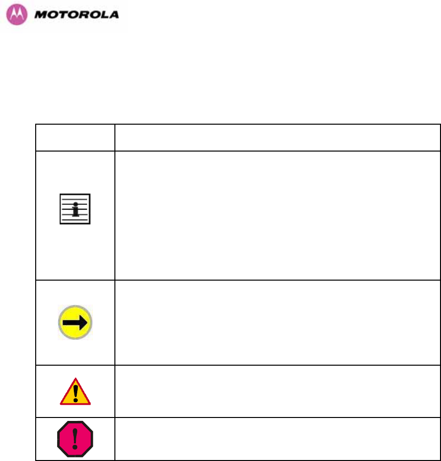
Admonition
Label General Message
Note Informative content that may:
• Defy common or cursory logic.
• Describe a peculiarity of the 600 Series solutions implementation.
• Add a conditional caveat.
• Provide a reference.
• Explain the reason for a preceding statement or provide background
for what immediately follows.
Recommendation Suggestion for an easier, quicker, or safer action or
practice.
Important Informative content that may:
• Identify an indication that you should watch for.
• Advise that your action can disturb something that you may not want
disturbed.
• Reiterate something that you presumably know but should always
keep in mind.
Caution! A notice that the risk of harm to equipment or service exists.
Warning! A notice that the risk of harm to person exists.
Table 2 - Admonition types

25
1.2 Getting Additional Help
To get information or assistance as soon as possible for problems that you encounter, use
the following sequence of action:
1. Search this document, the user manuals that support the modules, and the software
release notes of supported releases:
a. In the Table of Contents for the topic.
b. In the Adobe Reader® search capability for keywords that apply.4F
5
2. Visit the Motorola website at 464Hwww.motorola.com/ptp
3. Ask your Motorola products supplier to help.
4. Gather information from affected units such as:
a. the IP addresses and MAC addresses
b. the software releases
c. the configuration of software features
d. any available diagnostic downloads
5. Escalate the problem to Motorola Technical Support as follows. You may either:
a. Send e-mail to 465Hsupport.ptp@motorola.com
b. Call our 24/7 Technical Center on +1 (0) 877 515 0400 (Worldwide) and +44 (0)
808 234 4640 (UK).
For warranty assistance, contact your reseller or distributor for the process.
1.3 Sending Feedback
We welcome your feedback on the PTP 600 Series Bridge system documentation. This
includes feedback on the structure, content, accuracy, or completeness of our documents,
and any other comments you have.
5 Reader is a registered trademark of Adobe Systems, Incorporated.
26
2 Avoiding Hazards
2.1 Preventing Overexposure to RF Energy
Caution To protect from overexposure to RF energy, install the radios for the 600 family of
PTP wireless solutions so as to provide and maintain the minimum separation distances from
all persons as shown in 958HTable 3.
When the system is operational, avoid standing directly in front of the antenna. Strong RF
fields are present when the transmitter is on. The Outdoor Unit (ODU) must not be deployed
in a location where it is possible for people to stand or walk inadvertently in front of the
antenna.
At these and greater separation distances, the power density from the RF field is below
generally accepted limits for the general population.
Note These are conservative distances that include compliance margins.
2.1.1 Calculations for Separation Distances and Power Compliance Margins
Limits and guidelines for RF exposure come from:
• US FCC limits for the general population. See the FCC web site at 466Hhttp://www.fcc.gov,
and the policies, guidelines, and requirements in Part 1 of Title 47 of the Code of Federal
Regulations, as well as the guidelines and suggestions for evaluating compliance in FCC
OET Bulletin 65.
• Health Canada limits for the general population. See the Health Canada web site at
467Hhttp://www.hc-sc.gc.ca/rpb and Safety Code 6.
• ICNIRP (International Commission on Non-Ionizing Radiation Protection) guidelines for
the general public. See the ICNIRP web site at 468Hhttp://www.icnirp.de/ and Guidelines for
Limiting Exposure to Time-Varying Electric, Magnetic, and Electromagnetic Fields.
The applicable power density exposure limits from the documents referenced above are:
• 6 W/m2 for RF energy in the 900-MHz frequency band in the US and Canada.
• 10 W/m2 for RF energy in the 2.4-, 5.2-, 5.4-, and 5.8-GHz frequency bands.

27
Peak power density in the far field of a radio frequency point source is calculated as follows:
Rearranging terms to solve for distance yields
S
GP
d.4
.
π
=
2.1.1.1 Calculated Distances and Power Compliance Margins
959HTable 3 shows calculated minimum separation distances d, recommended distances and
resulting power compliance margins for each frequency band and antenna combination.
Variable Band Antenna Max
Average
Transmit
Power in
Burst
(Watt)
P (Watt) G S
(W/m2)
D1 (m) Recom-
mended
Distance
(m)
Power
Compliance
Margin
2.5 GHz Integrated 0.25 0.125
63
(18dBi) 10 0.25 2 8
5.4 GHz Integrated
0.005
(7dBm) 0.0025
200
(23dBi) 10 006 1 16
Integrated
0.32
(25dBm) 0.16
200
(23dBi) 10 0.5 2 4
External
2ft Flat
Plate
0.32
(25dBm) 0.16
631
(28dBi) 10 0.9 4 4.5
5.8 GHz
External
6ft Dish
0.32
(25dBm) 0.16
6310
(38dbi) 10 2.83 10 3.5
1. Calculated
Table 3 - Power Compliance Margins
Notes:
1. The regulations require that the power used for the calculations is the maximum power in
the transmit burst subject to allowance for source-based time-averaging.
2. At 5.4GHz the product is generally to a fixed EIRP which can be achieved with the
Integrated Antenna. If there are no EIRP limits, use the distance calculations for 5.8GHz.
3. At 5.8GHz, for antennas between 2ft and 6ft, alter the distance proportionally to the
antenna gain.
4. At 2.5GHz, with a 4/12ft dish, the safe distance is increased to 08/2.4m.
Where S = power density in W/m
2
P = Maximum Average transmit power capability of the radio, in W
G = total Tx gain as a factor, converted from dB
d = distance from point source, in m
2
4
.
d
GP
S
π
=

28
3 Getting Started
3.1 For Your Safety
WARNING: Use extreme care when installing antennas near power lines.
WARNING: Use extreme care when working at heights.
WARNING: The Outdoor Unit (ODU) for the PTP 600 Series Bridge must be properly
grounded to protect against lightning. It is the user’s responsibility to install the equipment in
accordance with Section 810 of the National Electric Code, ANSI/NFPA No.70-1984 or
Section 54 of the Canadian Electrical Code. These codes describe correct installation
procedures for grounding the outdoor unit, mast, lead-in wire and discharge unit, size of
grounding conductors and connection requirements for grounding electrodes. It is
recommended that installation of the outdoor unit be contracted to a professional installer.
WARNING: The ODU for the PTP 600 Series Bridge must be grounded to a Protective Earth
as described in Section 960H5.7.6 ”961H Grounding The Installation” of this Installation Manual and in
accordance with the Local Electrical Regulations.
WARNING: It is recommended that the supplied Power Indoor Plus (PIDU Plus) – PTP 600
Series is used to power the PTP 600 Series Bridge ODU. The use of other power sources
may invalidate safety approval and affect your warranty.
WARNING: When using alternate DC supplies (via the PIDU Plus DC in terminals as
described in Section 962H1.3.3 “963HRedundancy and Alternate Powering Configurations”), such as
battery-backed DC power source, the supply MUST comply with the following requirements:
• The voltage and polarity is correct and is applied to the correct terminals in the PIDU Plus
• The power source is rated as SELV
• The power source is rated to supply at least 1A continuously, and
• The power source cannot provide more than the Energy Hazard Limit as defined by
IEC/EN/UL6090, Clause 2.5, Limited Power (The Energy Hazard Limit is 240VA)
CAUTION: Users and installers should note that the main power supply is the primary
disconnect device.

29
CAUTION: Safety will be compromised if external quality cables are not used for connections
that will be exposed to the weather.
CAUTION: Safety will be compromised if a different power supply is used than the one
supplied by Motorola as part of the system.
3.2 Welcome
Congratulations on the purchase of the PTP 600 Series Bridge from Motorola. The PTP 600
Series Bridge is the latest innovation in high-speed wireless networking that lets you deploy
wireless networks in areas previously unattainable.
3.2.1 About This Guide
This guide covers the installation, commissioning, operation and fault finding of the PTP 600
Series Bridge.
3.2.2 Who Should Use This Guide
The guide is for use by the system installer and the end user IT professional.
The system installer will require expertise in the following areas:
• Outdoor radio equipment installation
• Network configuration
• Use of web browser for system configuration, monitoring and fault finding
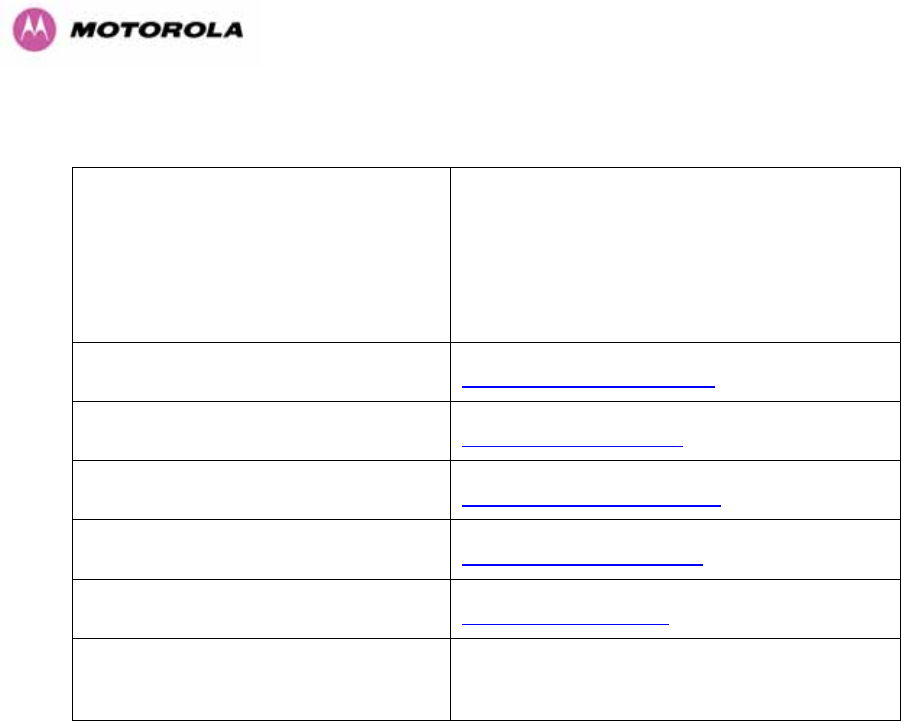
30
3.2.3 Contact Information
Postal Address:
Motorola, Inc.
Unit A1, Linhay Business Park,
Eastern Road,
Ashburton,
Devon. TQ13 7UP
United Kingdom
Web Site: 469Hhttp://www.motorola.com/ptp
Sales Enquiries: 470Hsales.ptp@motorola.com
Web Support: 471Hhttp://www.motorola.com/ptp/
Email Support: 472Hsupport.ptp@motorola.com
All Other Enquiries: 473Hinfo.ptp@motorola.com
Telephone Enquiries and Global
Support:
+1 (0) 877 515 0400 (Toll Free in the USA) and
+44 (0) 808 234 4640 (Toll Free in the Uk).
Table 4 - Contact Information
3.2.4 Repair and Service
For unit repair or service, contact your service provider or an authorized Motorola Point-to-
Point Distributor for Return Material Authorization (RMA) and shipping instructions.
Alternatively, contact the PTP Global Technical Support Center to process an RMA (following
troubleshooting).
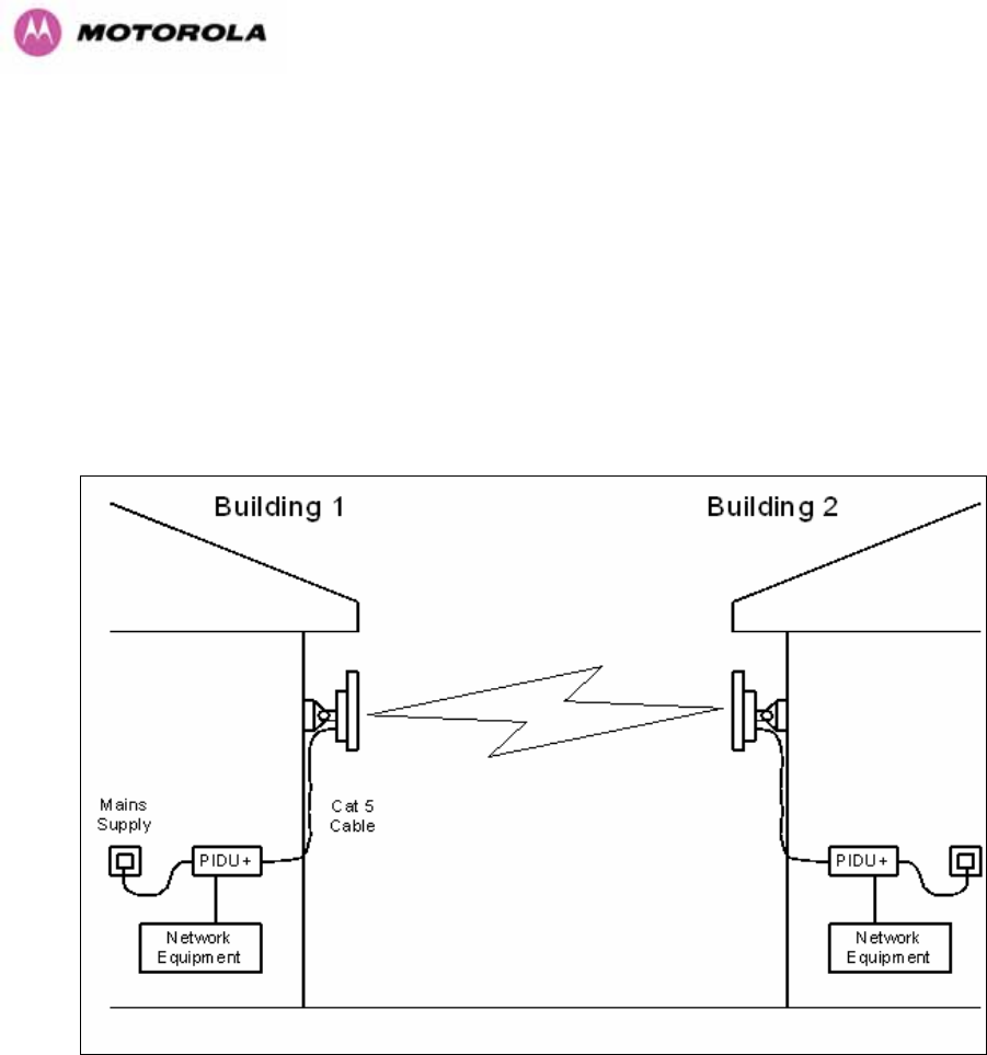
31
3.3 Product Description
This User Manual is specifically written for the 600 family of point-to-point broadband wireless
solutions. The PTP 600 Series Bridge has been developed to provide Point-to-Point data
connectivity via a 2.5 GHz, 5.4 GHz or 5.8 GHz wireless Ethernet bridge operating at
broadband data rates. The PTP 600 Series Bridge is aimed at a wide range of applications.
An example application is an enterprise that has a requirement to connect together the Local
Area Network (LAN) of two or more buildings as shown in 964HFigure 1.
Figure 1 - Typical PTP 600 Series Bridge Deployment
The PTP 600 Series Bridge offers true non-line-of-sight (NLOS) operation by using a
combination of Orthogonal Frequency Division Multiplexing (OFDM) modulation and Multiple-
Input Multiple-Output (MIMO) techniques. These technologies enable the PTP 600 Series
Bridge to drive through foliage and around buildings to such an extent that almost universal
coverage can be expected at short range.
A PTP 600 Series Bridge system consists of a pair of identical devices that are deployed one
at each end of the link. At installation, the user sets up one unit as the Master and the other
as the Slave. Either unit can be configured as Master or Slave.

32
Each end of the link consists of:
• An integrated outdoor transceiver unit containing all the radio and networking electronics
hereafter referred to as the Outdoor Unit (ODU).
• An indoor connection box containing a mains power supply, status indicators and network
connection port. Hereafter referred to as the Power Indoor Unit Plus (PIDU Plus).
A pair of units is normally supplied pre-configured as a link.
The network connection to a PTP 600 Series Bridge is made via a 1000BaseT Ethernet
connection. Power is provided to the ODU over the 1000BaseT Ethernet connection using a
patented non-standard powering technique.
Previous releases of the PTP 600 Series Bridge platform used different powering and
connection arrangements. Users of equipment prior to “Mod Record 1” should refer to the
User Guide shipped with the original equipment. The “Mod Record” label can be found on the
back of the ODU as shown in 965HFigure 2.
Figure 2 - Mod Record Label

33
Alternately, the network connection to a PTP 600 Series Bridge can be made using a
1000BaseSX Fiber Optic cable connected directly to the ODU. In this case power is still
provided over the 1000BaseT Ethernet connection. In the case of Fiber Optic cable failure the
PTP 600 Series Bridge will automatically fall back to the copper Ethernet connection
(provided the cable length <=100m [330 ft]). “PTP 600 Series Optical Interface Upgrade Kits”
can be obtained from your distributor, reseller or system integrator.
Power is fed into the PTP 600 Series Bridge PIDU Plus from the mains via a standard “figure
of eight” mains plug. Connection between the ODU and PIDU Plus is made using standard
CAT5e outdoor UV resistant cable. Connection between the PIDU Plus and the Network
Equipment is made using standard CAT5e cable.
3.3.1 The Outdoor Unit (ODU)
The ODU (966HFigure 3) is a self-contained unit. It houses both radio and networking electronics.
The ODU for the PTP 600 Series Bridge should only be deployed using the supplied PTP 600
Series Bridge PIDU Plus.
Figure 3 – PTP 600 Series Bridge Outdoor Unit (ODU)
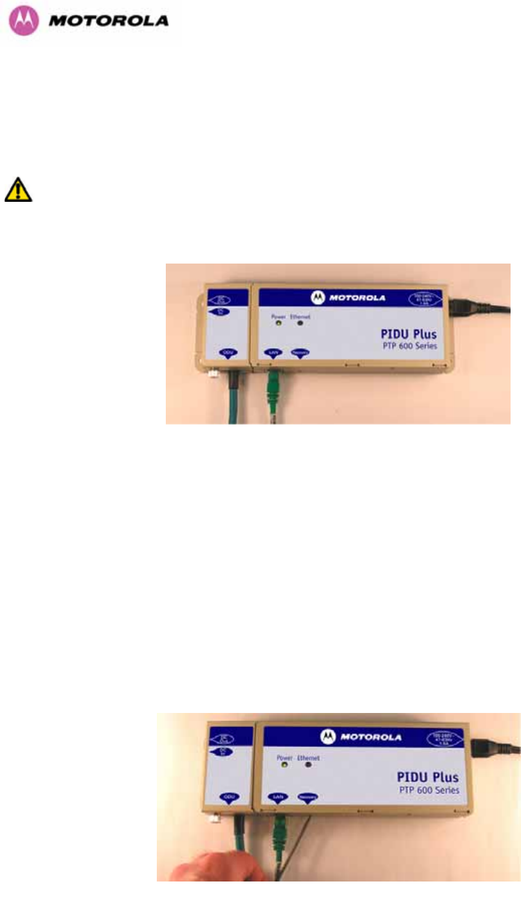
34
3.3.2 PIDU Plus – PTP 600 Series Bridge
The PTP 600 Series Bridge PIDU Plus is used to generate the ODU supply voltage from the
mains supply and inject this supply voltage into the 1000BaseT Ethernet connection to the
ODU. Connection uses a CAT5e cable using standard RJ45 wiring.
WARNING Care should be taken not to connect equipment other than an ODU for the PTP
600 Series Bridge to a PIDU Plus ODU port as equipment damage may occur. The PTP 600
Series Bridge PIDU Plus is not compatible with the PTP 600 Series Bridge PIDU Plus.
Figure 4 - Power Indoor Unit (PIDU Plus) – PTP 600 Series
The front panel contains indicators showing the status of the power and Ethernet
connections.
The power indicator is illuminated when the PIDU Plus is receiving mains power.
The Ethernet indicator normally illuminates when the Ethernet link is working, flashing when
there is Ethernet activity. The fact that it lights also indicates that the ODU is powered. At
power up the LED will flash 10 times to indicate that a correct start up sequence has
occurred. See Section 967H8 “968HFault Finding” for further fault finding information.
At the bottom of the PIDU Plus is an entry point for the PIDU Plus to ODU cable, the
1000BaseT Ethernet network port and the Recovery switch.
Figure 5 – PIDU Plus Recovery Switch Location

35
The Recovery switch is used to recover the unit from configuration errors or software image
corruption. To put a PTP 600 Series Bridge into Recovery mode the Recovery switch should
be pressed then the power applied. The Recovery switch should be kept pressed for at least
20 seconds after the power has been applied. Full instruction on the recovery mode can be
found in Section 969H9 “970HRecovery Mode”.
A simple reboot can be performed by removing and re-applying the mains power to the PTP
600 Series Bridge PIDU Plus.
On the left hand side of the PIDU Plus, 48V DC input and output connections can be found.
These are used to power the PTP 600 Series Bridge from an external DC source or to
provide a level of power supply redundancy, as shown in Section 971H1.3.3 “972HRedundancy and
Alternate Powering Configurations”.
WARNING When using alternate DC supplies the supply MUST comply with the following
requirements:
• The voltage and polarity is correct and is applied to the correct terminals in the PIDU Plus
• The power source is rated as SELV
• The power source is rated to supply at least 1A continuously, and
• The power source cannot provide more than the Energy Hazard Limit as defined by
IEC/EN/UL6090, Clause 2.5, Limited Power (The Energy Hazard Limit is 240VA)
Also on the left hand side of the PTP 600 Series Bridge PIDU Plus, connectors and jumpers
can be found that allow the remote connection of power LED, Ethernet LED and Recovery
switch. The connection instructions can be found in Section 973H1.3.4 “974HRemote LEDs and
Recovery Switch”
The input supply range for the 600 Series PIDU Plus is 100V-240V AC, 47-63Hz. Mains
connection to the PIDU Plus is made using a standard “figure of eight” mains lead as shown
in 975HFigure 6.
Figure 6 – PTP 600 Series Bridge PIDU Plus Power Input
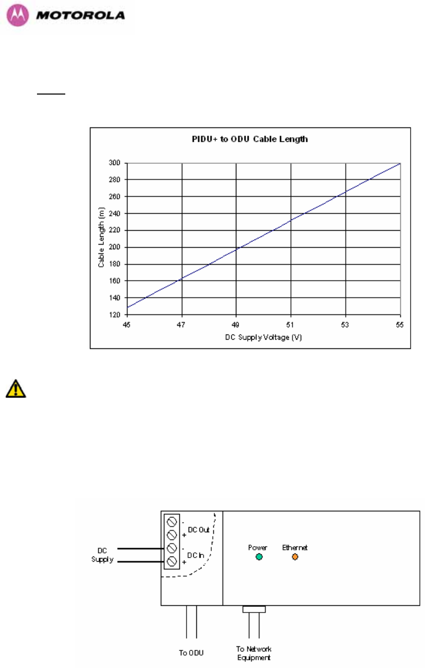
36
3.3.3 Redundancy and Alternate Powering Configurations
NOTE: The use of DC supplies of less than 55v will reduce the usable distance between the
PIDU Plus and ODU see 976HFigure 7.
Figure 7 – PTP 600 Series Bridge PIDU Plus to ODU Cable Length Graph
WARNING: The maximum distance from the ODU to the connected network equipment is
100m (330 ft) when using 1000BaseT. Powering distances over 100m (330 ft) are only
applicable when using a 1000BaseSX (Fiber Optic) connection.
3.3.3.1 External DC Supply Only
For use where there is no mains supply.
Figure 8 - External DC Supply Only
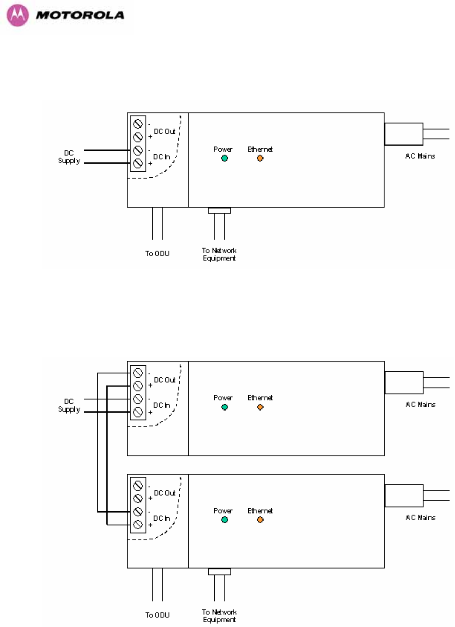
37
3.3.3.2 External DC Supply and AC Supply
To give redundancy through the use of mains and DC supply.
Figure 9 - External DC Supply and AC Supply
3.3.3.3 External DC Supply and Redundant AC Supply
To guard against mains failure, DC supply failure of PTP 600 Series Bridge PIDU Plus failure.
Figure 10 - External DC Supply and Redundant AC Supply
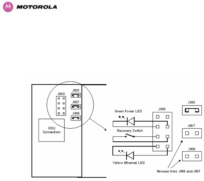
38
3.3.4 Remote LEDs and Recovery Switch
The PTP 600 Series Bridge PIDU Plus provides a facility to connect remote LEDs and
Recovery switch allowing the PIDU Plus to be mounted inside an enclosure. At the left hand
end of the PIDU Plus under the ODU connection cover can be found a PCB header and three
jumpers. Jumpers J906 and J907 should be removed and connection to the remote LEDs and
Recovery switch made to J908 as shown in 977HFigure 11.
Figure 11 - Remote LED and Recovery Switch Wiring
3.3.5 Cables and connectors
The cable used to connect the PTP 600 Series Bridge PIDU Plus to the ODU can be any
standard CAT5e type provided that it is suitable for outdoor deployment. Motorola
recommends that cables to the specification below be used:
NEC/CEC: CMR (ETL) C (ETL) 75C SUN RES OIL RES II
Failure to use the recommended (or equivalent) standard of cable may invalidate the
system’s safety certification.
The cable used to connect the PTP 600 Series Bridge PIDU Plus to the users Network
Equipment can be any standard CAT5e Cable.

39
The PIDU Plus to ODU and the PIDU Plus to Network Equipment cables may be unscreened
(UTP) or screened (STP). However, unscreened cables reduce the system’s ability to cope
with nearby lightning strikes. If lightning activity is common in the area of deployment, the use
of screened cable is highly recommended. See Section 978H10 “979HLightning Protection”.
The PIDU Plus provides screen continuity between the ODU and Network Equipment
connections.
The ODU network connection implements automatic MDI/MDI-X sensing and pair swapping
allowing connection to another piece of networking equipment or directly to end user
equipment.
3.3.6 Surge Arrestor
The PTP 600 Series Bridge PIDU Plus meets the low level static discharge specifications
identified in Section 980H23 “Specifications”, but does not provide lightning or surge suppression.
Installations will generally require lightning or surge suppression, a separate Ethernet surge
suppressor must be used and appropriately earthed. Suitable surge suppressors can be
sourced from your Motorola Point-to-Point Distributor or Solutions Provider. See Section 981H11
“Lightning Protection”.
3.3.7 Mounting Brackets
The PTP 600 Series Bridge is supplied with a mounting bracket suitable for mounting the
ODU to a pole of 50mm (2”) to 75mm (3”) in diameter. For more details on mounting, see
Section 982H7 “Installation”.
The bracket allows for adjustment in both azimuth and elevation. The bracket may be split
allowing the pole mount section of the bracket to be mounted to the pole first. This allows the
installer to take the weight of the unit and secure it, one handed, with a single mounting bolt.
The PIDU Plus can either be desk or wall mounted. The preference is wall mounted with the
cables dressed to a cable channel. Wall mounting is achieved by screwing through the
mounting lugs on either side of the unit. Remember to leave space for access to the
Recovery button. See Section 983H3.3.2.

40
3.3.8 Configuration and Management
Configuration and Management of the PTP 600 Series Bridge is implemented using an inbuilt
web server hosting a number of Configuration and Management web pages. This approach
allows Configuration and Management to be carried out on any standard web browsing
technology. The PTP 600 Series Bridge can also be managed remotely using the SNMP
management protocol. Connection to the bridge is via the Ethernet connection carrying the
bridge network traffic. Connection to the unit is via a preset IP address. This address can be
changed via the Network Interface Configuration web page. A full explanation of the available
web pages and their use can be found in Section 984H6 “985HWeb Page Reference”.
3.4 Warranty
Motorola’s standard hardware warranty is for one (1) year from date of shipment from
Motorola or a Motorola Point-to-Point Distributor. Motorola warrants that hardware will
conform to the current relevant published specifications and will be free from material defects
in material and workmanship under normal use and service. Motorola shall within this time, at
its own option, either repair or replace the defective product within thirty (30) days of receipt
of the defective product. Repaired or replaced product will be subject to the original warranty
period but not less than thirty (30) days.
Motorola warranty for software is for six (6) months from date of shipment from Motorola or
Distributor. Motorola warrants that software will perform substantially in accordance with the
published specifications for that release level of the software and will be free from material
defects in material and workmanship under normal use and service. Motorola shall within this
time correct or replace software to correct program or documentation errors.
IN NO EVENT SHALL MOTOROLA, INC. BE LIABLE TO YOU OR ANY OTHER PARTY
FOR ANY DIRECT, INDIRECT, GENERAL, SPECIAL, INCIDENTAL, CONSEQUENTIAL,
EXEMPLARY OR OTHER DAMAGE RISING OUT OF THE USE OR INABILITY TO USE
THE PRODUCT (INCLUDING, WITHOUT LIMITATION, DAMAGES FOR LOSS OF
BUSINESS PROFITS, BUSINESS INTERRUPTION, LOSS OF BUSINESS INFORMATION
OR ANY OTHER PECUNIARY LOSS, OR FROM ANY BREACH OF WARRANTY, EVEN IF
MOTOROLA, INC. HAS BEEN ADVISED OF THE POSSIBILITY OF SUCH DAMAGES.
(Some States in the USA do not allow the exclusion or limitation of incidental or consequential
damages, so the above exclusion or limitation may not apply to you.) IN NO CASE SHALL
MOTOROLA’S LIABILITY EXCEED THE AMOUNT YOU PAID FOR THE PRODUCT.

41
4 Product Architecture
The PTP 600 Series Bridge consists of an identical pair of units deployed one at each end of
the link. The radio link operates on a single frequency channel in each direction using Time
Division Duplex (TDD). One unit is deployed as a master and the other as a slave. The
master unit takes responsibility for controlling the link in both directions.
The non-line-of-sight (NLOS) aspects of the product are provided by Multiple-Input Multiple-
Output (MIMO), coupled with Orthogonal Frequency Division Multiplexing (OFDM)
modulation.
The PTP 600 Series Bridge has been developed to operate within license exempt frequency
bands as well as the licensed 2.5GHz band in the USA.
The current product range supports:
• USA BRS-EBS Post-Transition Band 2.5 GHz (2496 – 2690 GHz)
• ETSI 5.4 GHz band B (5.470-5.725 GHz)
• ETSI 5.8 GHz band C (5.725–5.850 GHz) and the USA 5 GHz ISM band
(5.725-5.850 GHz)
The PTP 600 Series Bridge has been designed to coexist with other users of the band in an
optimal fashion using a combination of Transmit Power Control (TPC), Spectrum
Management functionality and Antenna beam shape.
In order to maintain link availability, the product employs adaptive modulation techniques that
dynamically reduce the data rate in severe or adverse conditions. To the data network the
PTP 600 Series Bridge is implemented as a learning bridge. A learning bridge builds up a
picture of which addresses are connected to which port. This means that it will not bridge a
packet if it knows that the destination address is connected to the same port on which the
bridge saw the packet. 986HFigure 12 illustrates the PTP 600 Series Bridge layer diagram.
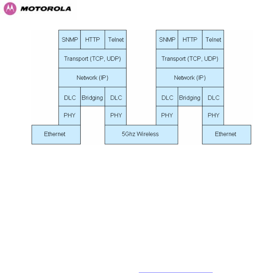
42
Figure 12 – PTP 600 Series Bridge Layer Diagram
The PTP 600 Series Bridge functionality has been extended to encompass the specification
IEEE 802.1p. IEEE 802.1p uses Ethernet packets extended by 4 bytes, as specified in IEEE
802.1q for VLAN tagging, to prioritize packets over the wireless interface. The PTP 600
Series Bridge will forward all VLAN tagged packets regardless of the VLAN ID value.
Each unit in the link is manageable through an IP connection. Standard IP protocols are
utilized for all management functions e.g. HP, SNMP, etc. The unit can be configured to use
VLAN tags on the management interfaces.
The PTP 600 Series Bridge is fully software upgradeable. New software images are first
downloaded from the Motorola website 474Hhttp://www.motorola.com/ptp to a convenient
computer. The image is then uploaded to the ODU via the web management page described
in Section 987H8.3.6 “988HSoftware Upgrade”. The compressed image is first loaded into RAM and
check-summed. If the compressed image transfer has completed successfully the image is
decompressed and written to flash memory. On completion of this process the unit can be
rebooted to use the newly uploaded image. Should this process fail, the unit will revert to a
protected compressed image installed during manufacturing to allow the unit to be recovered.

43
5 General Considerations
5.1 Spectrum Planning
The PTP 600 Series Bridge has three frequency variants in its product range.
Band Definition Frequency
Coverage
Variable
Channel
Width
Channel
Raster
2.5 GHz FCC BRS-EBS Post-
Transition Band
2496-2568 MHz
2572-2614 MHz
2618-2690 MHz
5, 10, 15 and
30 MHz5F
6 for
Lower, Middle
and Upper
bands
5.5 MHz
6 MHz
5.5 MHz
5.4 GHz ETSI 5 GHz band B, USA
UNII Band
5470-5725 MHz
5470-5725 MHz
5,10,15 MHz
30 MHz
6 MHz
10 MHz
5.8 GHz USA ISM Band / ETSI 5 GHz
band C
5725-5850 MHz
5725-5850 MHz
5,10,15 MHz,
30 MHz
6 MHz
10 MHz
Table 5 - PTP 600 Series Bridge Frequency Variants
6 30 MHz channel widths are available where allowed by local regulations and subject to some
restrictions on channel choice.

44
There are two distinct approaches to spectrum planning:
• First an operator can utilize the default spectrum management mode i-DFS
(intelligent Dynamic Frequency Selection). This mode uses the PTP 600 Series
Bridge ability to measure the interference levels in all channels to build up a picture of
the interference / noise levels in all channels. The PTP 600 Series Bridge uses
statistical techniques to select the most appropriate transmit and receive channels. I-
DFS can be influenced in its channel decision process by selectively barring channels
from use. The use of this functionality is described in detail in Section 989H8.3.7
“990HSpectrum Management”.
• Second, when detailed control of the spectrum allocation is required, it is
recommended that the fixed frequency mode is used to statically allocate transmit
and receive channels.
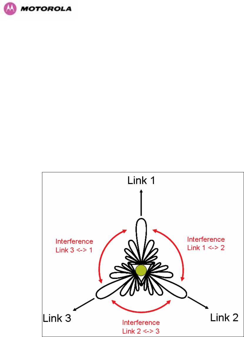
45
5.2 Introducing the Time Division Duplex (TDD) Synchronization Feature
5.2.1 The Problem
The TDD cycles from multiple links have different durations due to different link lengths. This
implies that one or both ends of multiple links interfere with each other when operating on the
same or adjacent channels. In addition, the different TDD durations make the TDD cycles
from multiple links “walk” relative to each other causing the interference to be intermittent.
Without the TDD Synchronization feature, angular/spatial separation and possible antenna
changes are required to solve the interference problem.
991HFigure 13 shows a simple example of three links of three different link lengths mounted on a
mast operating on the same or adjacent channels.
Figure 13 - Co-location of Links Interference Problem - A Simple Example
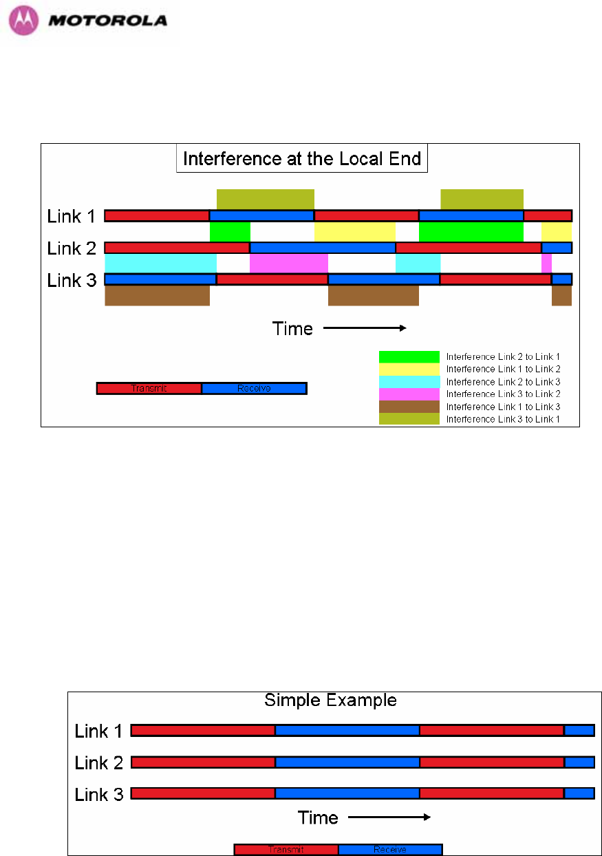
46
992HFigure 14 shows how is the interference shown using Transmit and Receive timing diagrams.
Figure 14 - Co-location of Links Interference Problem - TxRx Timing Diagram
5.2.2 The Solution – Using TDD Synchronization
The TDD synchronization feature introduces a fixed TDD framing mode, and allows frame
timing in a PTP link to be synchronized with an external reference. This means that all links in
a network may be made to transmit and receive in synchronism, implying reduced RF
interference between links.
Figure 15 - Co-location of Links Interference Problem - Solution to the Simple Example

47
5.2.3 Deployment Consideration
The following are deployment considerations:
• Fixed frequency operation ONLY
• Fixed TDD operation only, i.e. all synchronized links have same ratio master to slave.
• Not presently available when radar avoidance is enabled.
• Networks need to be carefully planned
5.2.4 PTP Approach for Using TDD Synchronization
The external timing reference will consist of a precise 1 Hz signal, synchronized in both phase
and frequency with a global (or at least network-wide) master. The master clock will be
provided by one GPS receiver per link. The GPS link will be fitted between the lightning
protection unit and the ODU.
The TDD frame structure will depend on primary characteristics of the overall network such
as the longest link and the maximum distance between interfering master and slave ODUs.
The ODU web management page contains an extension to the existing link installation wizard
to compute frame timings from these primary characteristics. The ODU additionally provides
an “expert mode” permitting frame timing details to be entered directly.
See Section 993H14 for TDD Synchronization installation and configuration guidelines.

48
5.3 Region Codes
The PTP 600 Series Bridge uses a system of Region Codes to control the operation of the
radio link. The Region Code is set by a License Key.
WARNING To meet the regulatory requirements of your region you should set the correct
Region Code by obtaining a new License Key from your reseller or distributor.
Region
Code
Frequency
Band
Regulations /
Countries
Max Tx
Power
EIRP
Limit
Operational
Restrictions
(see Section 994H5.4)
1 5.8 GHz FCC Compliant
(e.g. USA,
Canada, Taiwan,
Brazil)
25dBm None Reduced TX Power at
Band Edges see Section
995H5.6.2 “Transmit Power
Reduction at the Band
Edges”
2 5.8 GHz China 10dBm 33dBm
3 5.8 GHz Australia , Hong
Kong
13dBm 36dBm
4 5.8 GHz UK 13dBm 36dBm Radar and RTTT (Road
Transport and Traffic
Telematics, 5795 to
5815 MHz) Radar
Avoidance Enabled
5 5.8 GHz Singapore -3dBm 20dBm
6 5.8 GHz Eire 10dBm 33dBm
7 5.8 GHz Unregulated 25dBm 53dBm Radar and RTTT (Road
Transport and Traffic
Telematics, 5795 to
5815 MHz) Radar
Avoidance Enabled
8 5.4 / 5.8
GHz
Unregulated
/Internal Use
25dBm None
11 5.4 GHz Korea 20dBm 43dBm Band restricted : 5725
MHz to 5825 MHz

49
Region
Code
Frequency
Band
Regulations /
Countries
Max Tx
Power
EIRP
Limit
Operational
Restrictions
(see Section 996H5.4)
12 5.4 GHz ETSI, USA 7dBm 30dBm Radar Avoidance Enabled
13 5.4 GHz Australia,
Canada
7dBm 30dBm Radar Avoidance Enabled;
Weather Radar Band
(5600 to 5650MHz) barred
16 2.5 GHz USA 23dBm >=63dBm6F
7 Licensed Band operation
19 5.8 GHz India 13dBm 36dBm 5.825MHz to 5.850MHz
Only
Table 6 – PTP 600 Series Bridge Region Code Definitions
When shipped from the factory units7F
8 are configured as follows:
• PTP 600 Series Bridge 2.5 GHz – Region Code 16
• PTP 600 Series Bridge 5.4 GHz – Region Code 128F
9
• PTP 600 Series Bridge 5.8 GHz – Region Code 1
5.4 Operational Restrictions
5.4.1 Radar Avoidance
Radar Avoidance requires that equipment used in the region:
• Detects interference from other systems and avoids co-channel operation with these
systems, notably radar systems.
• Provide on aggregate a uniform loading of the spectrum across all devices, i.e. Fixed
Frequency operation is not allowed.
• Radar avoidance is not applicable to the PTP25600 product.
7 The EIRP limit is approximately 63dBm + 10 x Log(360/Antenna Azimuth BW)
8 Note that 2.5 GHz, 5.8GHz and 5.4GHz are different products.
9 Note that the Quickstart Guide also contains the license keys for region 10. This bars operation in
the Band 5600 – 5650 MHz and MUST be used for equipment deployed in Canada and Australia.

50
To address the primary aims the Spectrum Management algorithm implements a radar
detection function which looks for impulsive interference on the active channel only. If
impulsive interference is detected Spectrum Management will mark the current active channel
as having detected radar and initiate a channel hop to an available channel. The previous
active channel will remain in the radar detected state for thirty minutes after the last impulsive
interference pulse was detected. After the thirty minutes have expired the channel will be
returned to the available channel pool.
The radar detection algorithm will always scan the active channel for 60 seconds for radar
interference before using the channel. This compulsory channel scan will mean that there is a
60 seconds service outage every time radar is detected and that the installation time is
extended by 60 seconds even if there is found to be no radar on the channel.
NOTE: On system installation or start-up this extends the initial scan time of the Master unit
by 60 seconds. To address the “provide aggregate uniform loading of the spectrum across all
devices” requirement, the channel selection algorithm will choose a channel at random from a
list of available channels. The channel selection algorithm is initiated at link initialization and
when radar interference is detected.
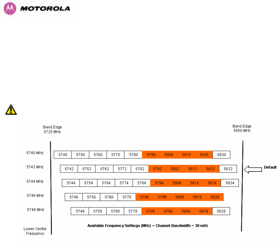
51
5.4.2 RTTT Avoidance and Other Channel Use Restrictions
Where regulatory restrictions apply to certain channels these channels are barred. The user
should note that the number of channels barred is dependant on the channel raster selected.
For example see the effect of the UK RTTT channel restrictions in 997HFigure 16. Barred channels
are indicated by a “No Entry” symbol displayed on the “Spectrum Management” web page,
see Section 998H8.3.9 “999HSpectrum Management Control - With Operational Restrictions”.
NOTE: “Radar Avoidance Enabled” is only valid with 30 MHz channel bandwidth.
Figure 16 - 5.8 GHz UK RTTT Channel Avoidance – 30 MHz Channel Bandwidth Only

52
5.4.3 Radar Avoidance, i-DFS and Variable (Narrow) Bandwidth Operation
PTP 600 Series bridges do not support operation with 5, 10 or 15 MHz channel bandwidth in
regions where radar avoidance is enabled.
NOTE: Radar avoidance requirements in the 5.4GHz band in the EU is detailed in
specification EN 301-893 version 1.3.1 and in the US in the specification FCC part 15.437.
Radar avoidance at 5.8GHz is applicable to EU operation and the requirements are currently
as defined in EN 301 893 version 1.3.1.
5.5 2.5GHz Specific Frequency Planning Considerations
The supported 2.5GHz frequency range is split into three bands, according to the bands
specified in the FCC BRS-EBS Post-Transition Band plan:
• Lower: 2496 MHz to 2572 MHz with a 5.5MHz channel raster (76 MHz total).
• Middle: 2572 MHz to 2614 MHz with a 6 MHz channel raster (42 MHz total).
• Upper: 2618 MHz to 2690 MHz with a 5.5 MHz channel raster (76 MHz total).
NOTE: When configured for 2.5 GHz operation, the unit will only operate in Fixed Frequency
mode, and the user is unable to select i-DFS.
NOTE: When configured for 2.5 GHz operation, the unit will default to TDM traffic mode,
rather than the IP Traffic default.
5.5.1 Variable Channel Bandwidth Operation
Channel bandwidths of 5, 10, 15 and 30MHz9F
10 are supported on the 05-00 software release
for both Full and Lite versions of the PTP 600.
Configuration of the variable bandwidth operation must be symmetric, i.e. the Transmit and
receive channels must use identical channel bandwidths.
NOTE: Hence, narrow bandwidth modes may not be used in regions where Radar Avoidance
is mandatory.
10 30MHz channel widths are available where allowed by local regulations and subject to some
restrictions on channel choice.

53
The 2.5 GHz product variant support channel centre frequencies as specified in 1000HTable 7.
Block Channel
Bandwidth
(MHz)
Channel Centre Frequencies (MHz)
5 2499.25, 2504.75, 2510.25, 2515.75, 2521.25, 2526.75, 2532.25, 2537.75,
2543.25, 2548.75, 2554.25, 2559.75, 2565.25
10 2502, 2507.5, 2513, 2518.5, 2524, 2529.5, 2535, 2540.5, 2546, 2551.5, 2557,
2562.5
15 2504.75, 2510.25, 2515.75, 2521.25, 2526.75, 2532.25, 2537.75, 2543.25,
2548.75, 2554.25, 2559.75
Lower
Band
Segment
30 2513, 2524, 2535, 2546
5 2575, 2581, 2587, 2593, 2599, 2605, 2611
10 2578, 2584, 2590, 2596, 2602, 2608
15 2581, 2587, 2593, 2599, 2605
Middle
Band
Segment
30 Not supported
5 2626.75, 2632.25, 2637.75, 2643.25, 2648.75, 2654.25, 2659.75, 2665.25,
2670.75, 2676.25, 2681.75, 2687.25
10 2629.5, 2635, 2640.5, 2646, 2651.5, 2657, 2662.5, 2668, 2673.5, 2679, 2684.5
15 2632.25, 2637.75, 2643.25, 2648.75, 2654.25, 2659.75, 2665.25, 2670.75,
2676.25, 2681.75
Upper
Band
Segment
30 2640.5, 2651.5, 2662.5, 2673.5
Table 7 - 2.5 GHz Product Variant Channel Plan
The channel centre frequencies listed above have been selected to align with the so-called
post-transition BRS channels as shown in 1001HFigure 17.
NOTE: The 2.5 GHz frequency variant supports three portions of the BRS spectrum
allocation. These are configurable at installation and constrain the wireless to operate in a
limited portion of the RBS spectrum. The three frequency bands are as shown in 1002HFigure 17:
Band 1: channels A, B, C and D (16.5 MHz blocks)
Band 2: channels A through G (6 MHz blocks)
Band 3: channels E, F, G and H (16.5 MHz blocks).
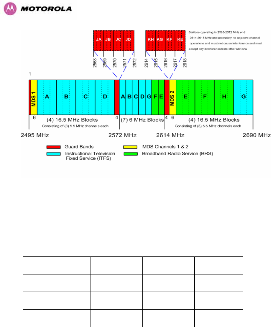
54
Figure 17 - 2.5 GHz BRS Band Channel Assignments
5.5.2 Power Reduction in the Upper Band
Operation in the Upper Band Segment (1003HTable 8 - Power Reduction in the Upper Band) will
result in a lower maximum transmit power and the reduction depends on the channel
bandwidth. The maximum power levels produced are shown below
Band 15MHz Channel 10MHz Channel 5MHz Channel
Lower Band Segment 23dBm 23dBm 23dBm
Middle Band Segment 23dBm 23dBm 23dBm
Upper Band Segment 23dBm 22dBm 21dBm
Table 8 - Power Reduction in the Upper Band
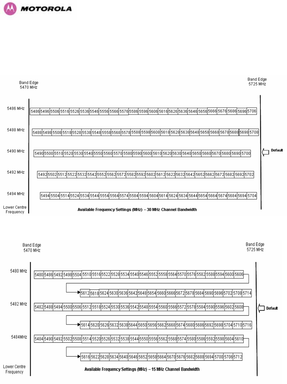
55
5.6 5.4GHz Specific Frequency Planning Considerations
Adjustment of the lower centre frequency allows the operator to slide the available frequency settings
up and down the 5.4 GHz band. See 1004HFigure 18 to 1005HFigure 21.
Figure 18 - 5.4 GHz Available Spectrum Settings - 30 MHz Channel Bandwidth
Figure 19 - 5.4 GHz Available Spectrum Settings - 15 MHz Channel Bandwidth
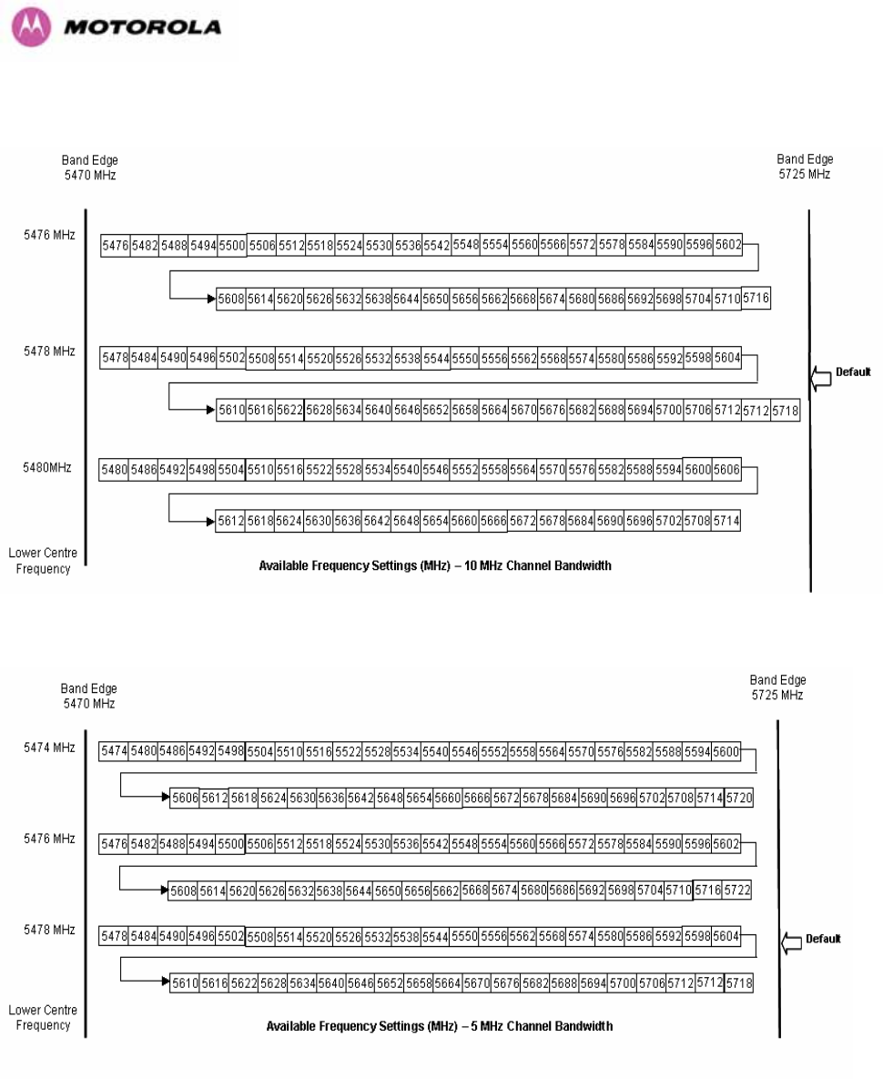
56
Figure 20 - 5.4 GHz Available Spectrum Settings - 10 MHz Channel Bandwidth
Figure 21 - 5.4 GHz Available Spectrum Settings - 5 MHz Channel Bandwidth
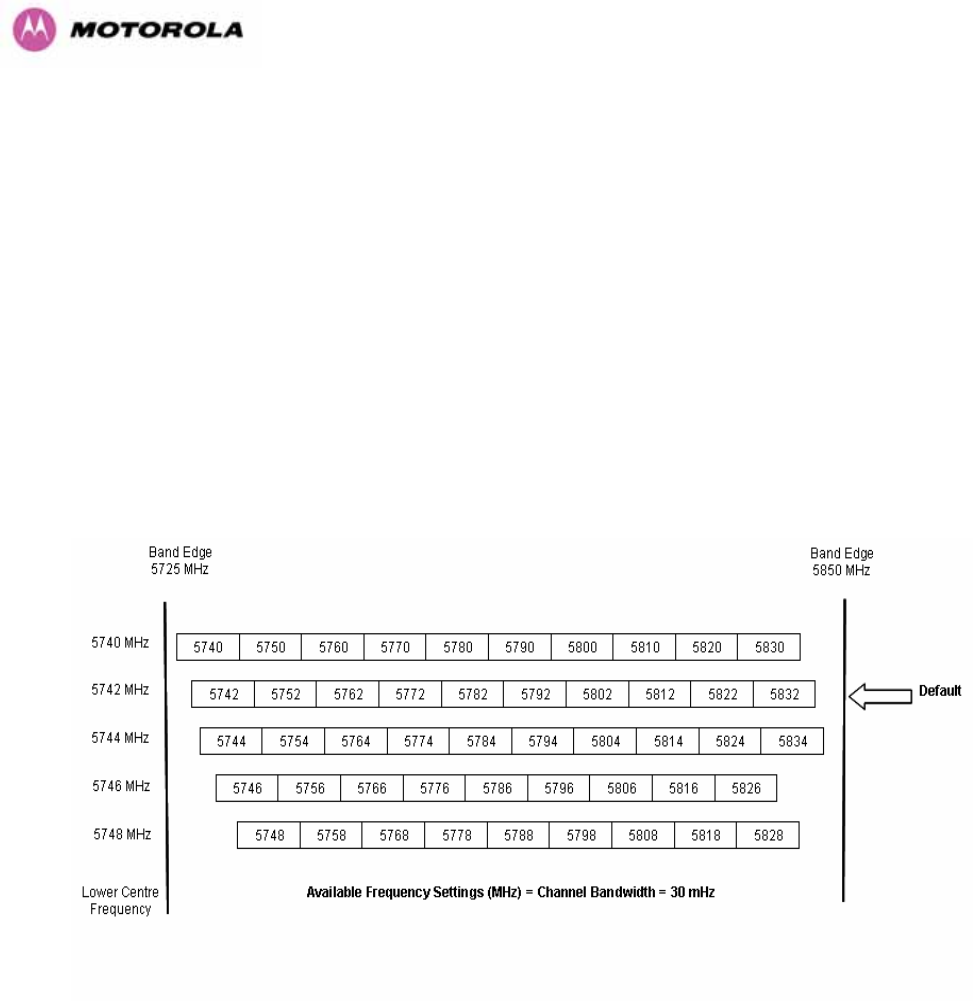
57
5.6.1 Raster Considerations
The PTP 600 Series Bridge 5.4 GHz variant operates on a 10 MHz channel raster (for 30 MHz
channel bandwidth) and 6 MHz for the variant channel bandwidths 5, 10 and 15 MHz. The channel
raster is set to even centre frequencies. See 1006HFigure 18 to 1007HFigure 21.
5.6.2 Transmit Power Reduction at the Band Edges
The 5.4 GHz product variant does not apply any band edge power reduction.
5.7 5.8GHz Specific Frequency Planning Considerations
Adjustment of the lower center frequency allows the operator to slide the available frequency
settings up and down the 5.8 GHz bands. 1008HFigure 22 to 1009HFigure 25 show the available spectrum
depending on the channel width (30 MHz, 15 MHz, 10 MHz and 5 MHz respectively).
Figure 22 - 5.8 GHz Available Spectrum Settings – 30 MHz Channel Bandwidth
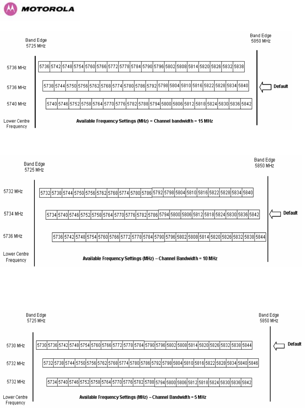
58
Figure 23 - 5.8 GHz Available Spectrum Settings - 15 MHz Channel Bandwidth
Figure 24 - 5.8 GHz Available Spectrum Settings - 10 MHz Channel Bandwidth

59
Figure 25 - 5.8 GHz Available Spectrum Settings - 5 MHz Channel Bandwidth
5.7.1 Raster Considerations
The PTP 600 Series Bridge 5.8 GHz variant operates on a 10 MHz channel raster (for 30
MHz channel bandwidth) and 6 MHz for the variant channel bandwidths 5, 10 and 15 MHz.
The channel raster is set to even center frequencies. See 1010HFigure 22 to 1011HFigure 25.
5.7.2 Transmit Power Reduction at the Band Edges
Operation at or near the 5.8 GHz band edges can results in a lower maximum transmit power.
In some configurations the PTP 600 Series Bridge solution reduces the power when
operating at the edge channels. The amount of reduction, if any, is dependant on the region
code of the region of operation. This currently only affects systems configured with Region
Code 1.
The power reduction in the edge channels for 5 MHz, 10 MHz and 15 MHz is presented in
1012HTable 9 (for region code 1 ONLY).
Power levels
Channel
Centre
5728 5730 5732 5734 5736 5738-
5836
5838 5840 5842 5844 5846
Channel
Width
5 19 25 25 25 25 25 25 25 25 25 23
10 N/A N/A 23 25 25 25 25 25 23 19 N/A
15 N/A N/A N/A 19 23 25 25 23 19 N/A NA
Table 9 - 5.8 GHz Band Edge Tx Power Reduction –
Channel Bandwidth 5, 10, 15 MHz Only
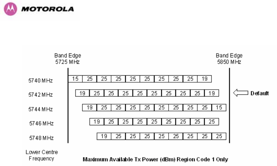
60
The power reduction in the edge channels for 30 MHz is presented in 1013HFigure 26.
Figure 26 - 5.8 GHz Band Edge TX Power Reduction (Region Code 1 Only) – 30 MHz
Channel Bandwidth Operation
5.8 Distance
The PTP 600 Series Bridge will operate at ranges from 100 m (330 ft) to 200 km (124 miles),
within 3 modes: 0-40km (0-25 miles), 0-100km (0-62 miles) and 0-200km (0-124 miles).
Operation of the system will depend on obstacles in the path between the units. Operation at
40 km (25 miles) or above will require a near line-of-sight path. Operation at 100m (330 ft)
could be achieved with one unit totally obscured from the other unit, but with the penalty of
transmitting at higher power in a non-optimal direction, thereby increasing interference in the
band. This subject is covered in more detail in Section 1014H6.1.3 “1015HPath Loss Considerations“.

61
5.9 Networking Information
The PTP 600 Series Bridge operates as a transparent Ethernet bridge. Each unit requires an
IP address. This IP address is for management purposes only and it plays no part in the
operation of the system. IP addresses are assigned during initial configuration as described in
Section 1016H7.2 “Installation Procedure”.
5.10 Lightning Protection
The amount of lightning protection is dependent on regulatory requirements and the end user
requirements. The standard ODU for the PTP 600 Series Bridge is fitted with surge limiting
circuits and other features to minimize the risk of damage due to nearby lightning strikes.
These standard features may require some additional equipment to be configured as part of
the system installation to be fully effective. Motorola recommends the use of screened cable
and a surge arrestor to protect connected equipment from nearby strikes.
NOTE: The PTP 600 Series Bridge is not designed to survive direct lightning strikes. For this
reason the unit should not be installed as the highest point in a localized area, unless specific
precautions are taken. See Section 1017H11 “Lightning Protection”.
5.11 Electrical Requirements
The PTP 600 Series Bridge is supplied with a variable input voltage (100-240V, 47-63Hz AC)
inline power supply unit which is incorporated into the Power Indoor Unit (PIDU Plus). The
PTP 600 Series Bridge requires one mains supply outlet at each end of the link.

62
6 Site Planning
6.1 Site Selection Criteria
The following are guidelines for selecting the installation location of the ODU and PDU Plus
for a PTP 600 Series Bridge.
6.1.1 ODU Site Selection
When selecting a site for the ODU the following should be taken into consideration:
• It is not possible for people to stand or walk inadvertently in front of the antenna
• Height and location to achieve the best radio path
• Height in relation to other objects with regard to lightning strikes
• Protection from the weather
• Aesthetics and planning permission issues
• Distance from the ODU and connected Network equipment (Maximum cable run from the
ODU to the connected equipment is 100m [330 ft])
• Distance from the PIDU Plus to the ODU (Maximum cable run from the PIDU Plus to the
ODU is 100m [330 ft] when using the 1000BaseT interface)
6.1.2 PTP 600 Series Bridge PIDU Plus Site Selection
When selecting a site for the PIDU Plus the following should be taken into consideration:
• Availability of a mains electricity supply
• Accessibility for viewing status indicators and pressing reset switch (See Section 1018H3.3.2
and Section 1019H10)

63
6.1.3 Path Loss Considerations
The path loss is the amount of attenuation the radio signal undergoes between the two ends
of the link. The path loss is the sum of the attenuation of the path if there were no obstacles in
the way (Free Space Path Loss), the attenuation caused by obstacles (Excess Path Loss)
and a margin to allow for possible fading of the radio signal (Fade Margin).
capabilityseasonalfadeexcessspacefree LLLLL
<
+
+
+
_
Where
spacefree
L_ Free Space Path Loss (dB)
excess
L Excess Path Loss (dB)
fade
L Fade Margin Required (dB)
seasonal
L Seasonal Fading (dB)
capability
L Equipment Capability (dB)
Equation 1 - Path Loss
6.1.4 Definitions
Sensitivity: Sensitivity is defined as the combined receive input signal level on both horizontal
and vertical inputs that produces a Null BER Error ratio of 3x10⁻⁷.
Output Power: The output power shown is for a centre channel in Region 1. The output power
will be reduced on the edge channels and may vary if different region codes are selected.
AMOD Threshold: The AMOD threshold is the combined receive input signal level on both
horizontal and vertical inputs that results in the link consistently entering the receive
modulation mode under consideration as the signal level is increased.
System Threshold: Thresholds for all modes except BPSK are for the relevant link
optimization AMOD thresholds. System threshold for BPSK is the RPSK receive sensitivity.
Max Link Loss: The maximum link loss for each modulation mode is derived from the AMOD
threshold for that mode (sensitivity threshold for BPSK) and the maximum Region 1 centre
channel output power. The figures assume integral antennas with 23 dBi gain are used.
64
6.1.5 2.5 GHz Product Variant - Receive Sensitivity, Link Loss, Output Power and Threshold Vs
Modulation Mode
The equipment capability is given in 1020HTable 10. This table gives Receive Sensitivity, Link Loss
and Output Power for PTP 600 Series Bridge in all modulation modes for channel bandwidth
equal to 30 MHz. Adaptive modulation will ensure that the highest throughput that can be
achieved instantaneously will be obtained taking account of propagation and interference.
The calculation of 1021HEquation 1 needs to be performed to judge whether a particular link can be
installed. When the link has been installed, web pages provide information about the link loss
currently measured by the equipment both instantaneously and averaged. The averaged
value will require maximum seasonal fading to be added, and then the radio reliability of the
link can be computed.
Threshold
V
alue
(
dBm
)
Output
Power
(
dBm
)
Maximum
Link Loss
(
dB
)
Channel Bandwidth (MHz)
Modulation Mode
5
MHz
10
MHz
15
MHz
30
MHz
All
Bandwidths
5
MHz
10
MHz
15
MHz
30
MHz
BPSK 0.63 single -97.95 -95.25 -91.36 -88.9 +23 158.0 155.3 151.4 150.1
QPSK 0.63 single -96.29 -93.76 -85.17 -85.4 +23 151.2 148.9 145.2 144.5
QPSK 0.87 single -93.79 -90.38 -81.06 -82.4 +23 148.0 144.5 141.1 140.6
16QAM 0.63 single -91.49 -88.25 -79.20 -80.1 +23 145.6 142.4 139.2 138.5
16QAM 0.63 dual -88.69 -84.55 -76.21 -77.0 +23 143.0 138.9 136.2 135.6
16QAM 0.87 single -86.83 -83.59 -73.28 -75.9 +23 140.5 136.5 133.3 132.6
16QAM 0.87 dual -84.16 -80.29 -70.08 -71.8 +23 137.2 132.6 130.1 129.1
64QAM 0.75 single -84.69 -81.37 -70.38 -73.0 +23 137.5 133.6 130.4 129.7
64QAM 0.75 dual -81.77 -77.83 -67.01 -68.6 +23 134.3 129.4 127.0 126.1
64QAM 0.92 single -80.36 -76.93 -68.62 -67.6 +23 135.1 131.7 128.6 130.6
64 QAM 0.92 dual -77.33 -73.87 -65.19 -63.9 +23 132.4 127.6 125.2 124.3
256QAM 0.81 single -77.92 -74.50 -65.50 -65.4 +23 132.3 132.4 125.5 124.6
256QAM 0.81 dual -75.28 -71.24 -62.24 -61.0 +23 129.4 128.1 122.2 120.5
Table 10 - 2.5GHz – Receive Sensitivity, Link Loss, Output Power and Threshold Vs
Modulation Mode
65
6.1.6 5.4 GHz Product Variant - Receive Sensitivity, Link Loss, Output Power and Threshold Vs
Modulation Mode
The equipment capability is given in 1022HTable 11. This table gives Receive Sensitivity, Link Loss
and Output Power for PTP 600 Series Bridge in all modulation modes for channel bandwidth
equal to 30 MHz. The values for Receive Sensitivity are typical values in a flat radio channel
for an Ethernet frame loss rate of 3E-5. For minimum error rates on TDM links the maximum
modulation mode should be limited to 64QAM 0.75.
The un-shaded value above (BPSK) is a static receive sensitivity measurement. The shaded
values above are static receive sensitivity measurements with an AMOD threshold applied.
The AMOD threshold applied is for a benign radio channel.
Threshold
V
alue
(
dBm
)
Output
Power
(
dBm
)
Maximum
Link Loss
(
dB
)
Channel Bandwidth (MHz)
Modulation Mode
5
MHz
10
MHz
15
MHz
30
MHz
All
Bandwidths
5
MHz
10
MHz
15
MHz
30
MHz
BPSK 0.63 single N/A N/A -93.39 N/A +25 N/A N/A 165.4 N/A
QPSK 0.63 single N/A N/A -90.55 N/A +24 N/A N/A 157.9 N/A
QPSK 0.87 single N/A N/A -87.22 N/A +23 N/A N/A 152.6 N/A
16QAM 0.63 single N/A N/A -85.51 N/A +22 N/A N/A 149.3 N/A
16QAM 0.63 dual N/A N/A -82.50 N/A +22 N/A N/A 145.5 N/A
16QAM 0.87 single N/A N/A -80.57 N/A +20 N/A N/A 142.5 N/A
16QAM 0.87 dual N/A N/A -77.68 N/A +20 N/A N/A 138.8 N/A
64QAM 0.75 single N/A N/A -78.45 N/A +18 N/A N/A 136.8 N/A
64QAM 0.75 dual N/A N/A -74.15 N/A +18 N/A N/A 133.3 N/A
64QAM 0.92 single N/A N/A -73.70 N/A +18 N/A N/A 132.4 N/A
64 QAM 0.92 dual N/A N/A -70.64 N/A +18 N/A N/A 127.5 N/A
256QAM 0.81 single N/A N/A N/A N/A +18 N/A N/A N/A N/A
256QAM 0.81 dual N/A N/A N/A -61.0 +18 N/A N/A N/A 126.0
Table 11 – 5.4GHz – Receive Sensitivity, Link Loss, Output Power and Threshold Vs
Modulation Mode
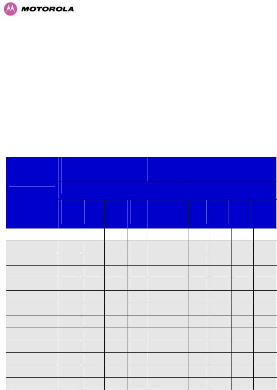
66
6.1.7 5.8 GHz Product Variant - Receive Sensitivity, Link Loss, Output Power and Threshold Vs
Modulation Mode
The equipment capability is given in 1023HTable 12. This table gives Receive Sensitivity, Link Loss
and Output Power for PTP 600 Series Bridge in all modulation modes for channel bandwidth
equal to 30 MHz. The values for Receive Sensitivity are typical values in a flat radio channel
for an Ethernet frame loss rate of 3E-5. For minimum error rates on TDM links the maximum
modulation mode should be limited to 64QAM 0.75.
The un-shaded value above (BPSK) is a static receive sensitivity measurement. The shaded
values above are static receive sensitivity measurements with an AMOD threshold applied.
The AMOD threshold applied is for a benign radio channel.
Threshold
V
alue
(
dBm
)
Output
Power
(
dBm
)
Maximum
Link Loss
(
dB
)
Channel Bandwidth (MHz)
Modulation Mode
5
MHz
10
MHz
15
MHz
30
MHz
All
Bandwidths
5
MHz
10
MHz
15
MHz
30
MHz
BPSK 0.63 single N/A -93.81 N/A N/A +25 N/A 165.8 N/A N/A
QPSK 0.63 single N/A -91.57 N/A N/A +24 N/A 161.0 N/A N/A
QPSK 0.87 single N/A -88.96 N/A N/A +23 N/A 156.1 N/A N/A
16QAM 0.63 single N/A -87.29 N/A N/A +22 N/A 153.2 N/A N/A
16QAM 0.63 dual N/A -81.31 N/A N/A +22 N/A 148.8 N/A N/A
16QAM 0.87 single N/A -82.63 N/A N/A +20 N/A N/A N/A N/A
16QAM 0.87 dual N/A -76.05 N/A N/A +20 N/A 140.8 N/A N/A
64QAM 0.75 single N/A -79.91 N/A N/A +18 N/A N/A N/A N/A
64QAM 0.75 dual N/A -74.08 N/A N/A +18 N/A 135.4 N/A N/A
64QAM 0.92 single N/A -75.36 N/A N/A +18 N/A N/A N/A N/A
64 QAM 0.92 dual N/A -69.43 N/A N/A +18 N/A 132.7 N/A N/A
256QAM 0.81 single N/A -73.10 N/A N/A +18 N/A N/A N/A N/A
256QAM 0.81 dual N/A -66.70 N/A N/A +18 N/A 130.0 N/A N/A
Table 12 - 5.8GHz – Receive Sensitivity, Link Loss, Output Power and Threshold Vs
Modulation Mode

67
7 Installation
Motorola recommends that only qualified personnel undertake the installation of a PTP 600
Series Bridge solution.
7.1 Preparation
Before proceeding with the installation you should:
• Check the contents of all packages against the parts lists shown in the packing list.
• Ensure that you have the correct tools for the job.
• Ensure that you are qualified to undertake the work.
• Ensure that you have taken the correct safety precautions.
• Have completed the site planning as described in Section 1024H6 “Site Planning”.
7.2 Installation Procedure
The 600 Series installation procedure consists of the following steps:
• Mounting the ODUs, Section 1025H7.6
• Connecting up, Section 1026H7.7
• Mounting the PIDU Plus units, Section 1027H7.7.8
• Powering Up, Section
1028H7.7.10
• Aligning the ODUs, Section 1029H7.7.11
7.3 Tools Required
The following specific tools are required to install a PTP 600 Series Bridge in addition to
general tools:
• 13mm Spanner / Wrench
• RJ45 Crimp Tool
• IBM Compatible Personal Computer (PC) running Windows 98 or later with 10, 100 or
1000 BaseT Ethernet (Ability to change IP settings easily is recommended)
• Either Internet Explorer version 6 or higher, or FireFox 1.5 or higher are recommended.
• Ethernet patch cable
• 6mm general purpose crimp tool for the grounding lug (optional for Lightning Protection)

68
7.4 Installation Support
Online installation support and contact details for your regional support can be found at
475Hhttp://www.motorola.com/ptp
A Frequently Asked Questions (FAQ) section can be found in Section 1030H21.
7.5 Legal Disclaimer
IN NO EVENT SHALL MOTOROLA, INC. BE LIABLE FOR ANY INJURY TO ANY PERSONS
OR ANY DAMAGE CAUSED DURING THE INSTALLATION OF THE MOTOROLA PTP 600
SERIES PRODUCT.
7.6 Mounting the ODUs
The ODU mounting bracket is designed to ease installation by fixing the bracket to a pole and
then bringing the ODU into position using a single bolt fixing. The ODU should be mounted
using the following steps ensuring that the cable entry is at the bottom.
The ODU mounting bracket is design to work with poles with diameters in the range 50mm
(2”) to 75mm (3”).
Step 1: Mount the bracket to the pole. Step 2: Mate the unit to the bracket together
and tighten the nut and bolt.
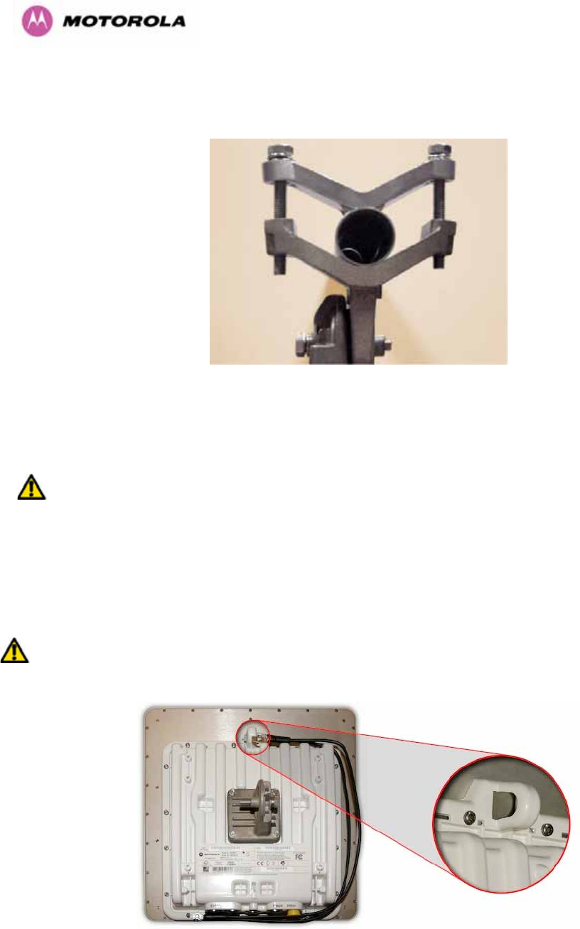
69
Pole diameters of 25mm (1”) to 50mm (2”) can be accommodated by inverting the back of the
bracket as shown in 1031HFigure 27.
Figure 27 - Mounting to pole diameters 25mm (1”) to 50mm (2”)
When adjustment is complete tighten all bolts to 14Nm (11lb ft).
Warning: Do not over tighten the bolts as bracket failure may occur.
The enclosure and mounting brackets of the PTP 600 Series Bridge product range are
capable of withstanding wind speeds up to 151mph (242kph). The installer should ensure that
the structure the bridge is fixed to is also capable of withstanding the prevalent wind speeds
and loads. See Section 1032H11 “Wind Loading”.
The integral safety loop should be used both for hoisting the ODU up a mast or building and
into position, and also as a fixing point to secure a permanent safety lanyard from the
tower/building to the ODU in case of mounting failure.
Figure 28 - Integral Safety Loop
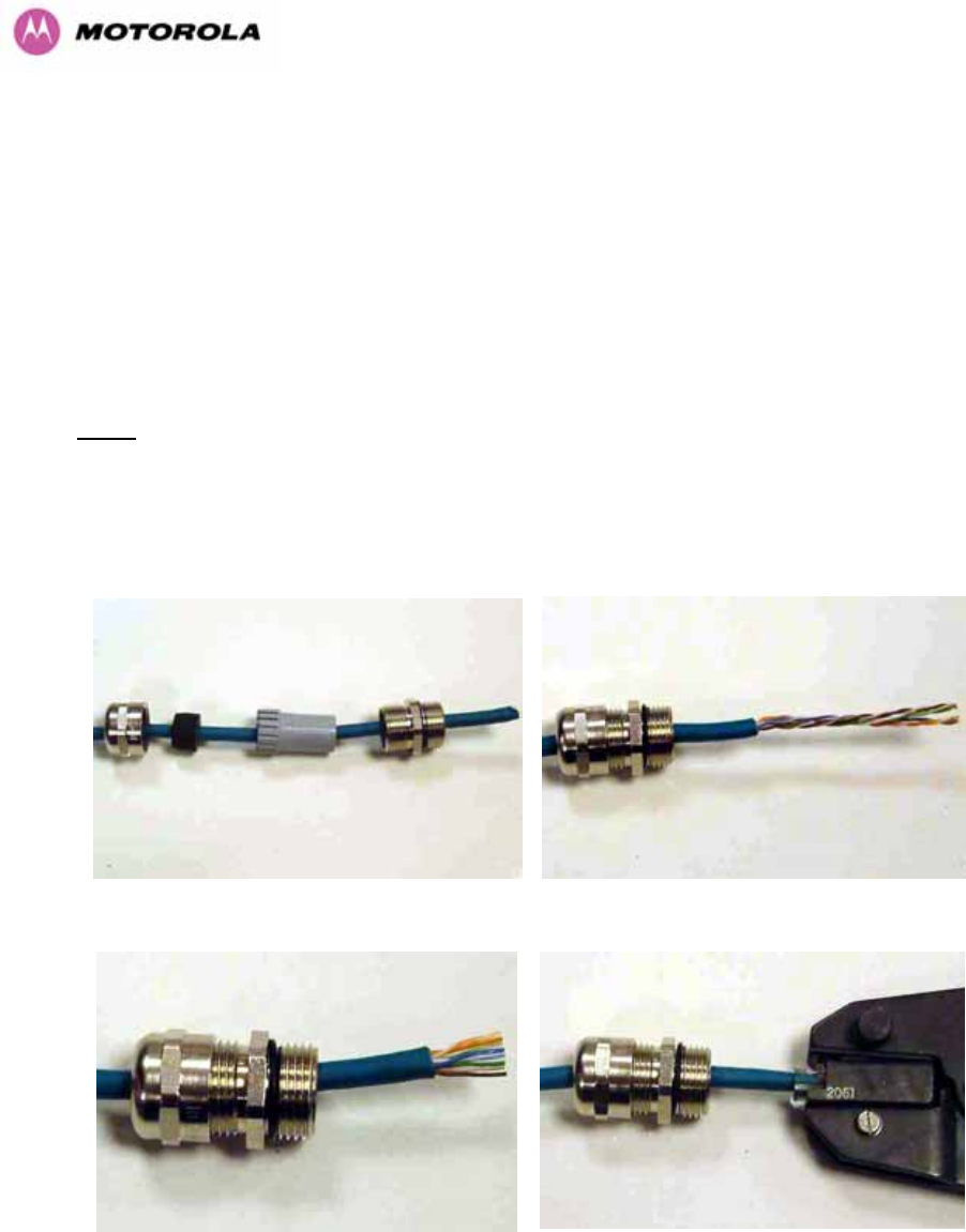
70
The length of the safety lanyard must not exceed 1m (approx 3 ft) in length. The lanyard
should be made from a material that does not degrade in an outdoor environment.
The safety lanyard must be fixed to a separate fixing point that is not part of the direct
mounting system for the ODU.
7.7 Connecting Up
7.7.1 Preparing The PIDU Plus To ODU Cable
NOTE: The maximum cable length between the ODU and the user’s Network Equipment is
100m (330 ft). Cable lengths up to 300m (984 ft) can be used where the PIDU Plus to ODU
cable is supplying power only, i.e., when using the PTP 600 Series Bridge Optical Interface.
The cable should be assembled to the following instructions:
Step 1: Assemble gland on cable as shown Step 2: Strip the outer insulation
Step 3: Arrange conductors as shown in
1033HFigure 19 and cut to length
Step 4: Insert conductors and crimp
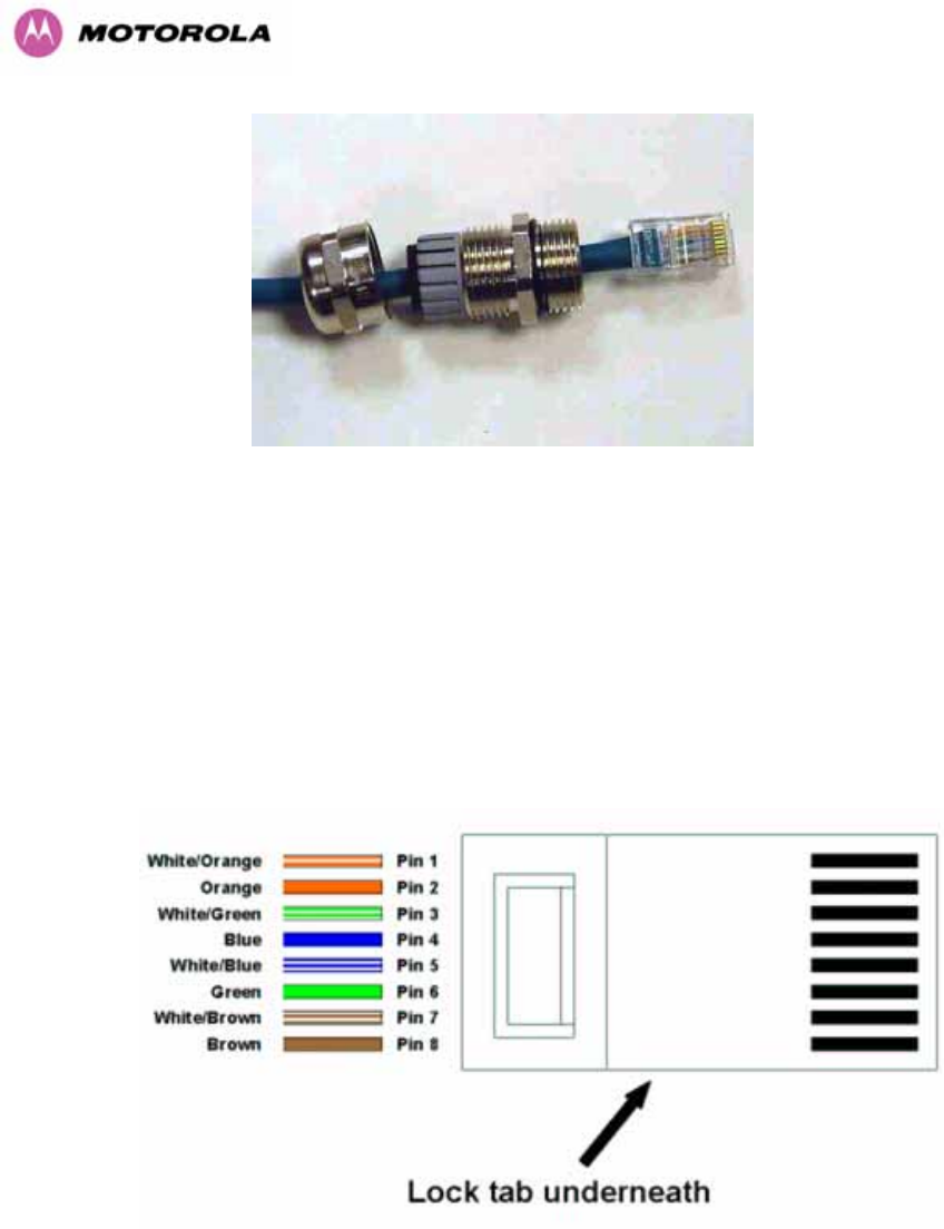
71
Figure 29 - Completed ODU connector
Both ends of the ODU cable are terminated in the same way. The above procedure should be
repeated for the PIDU Plus end of the cable when the cable routing process is complete.
NOTE: The PIDU Plus end of the cable does not employ a cable gland.
Figure 30 - RJ45 Pin Connection (T568B Color Coding)
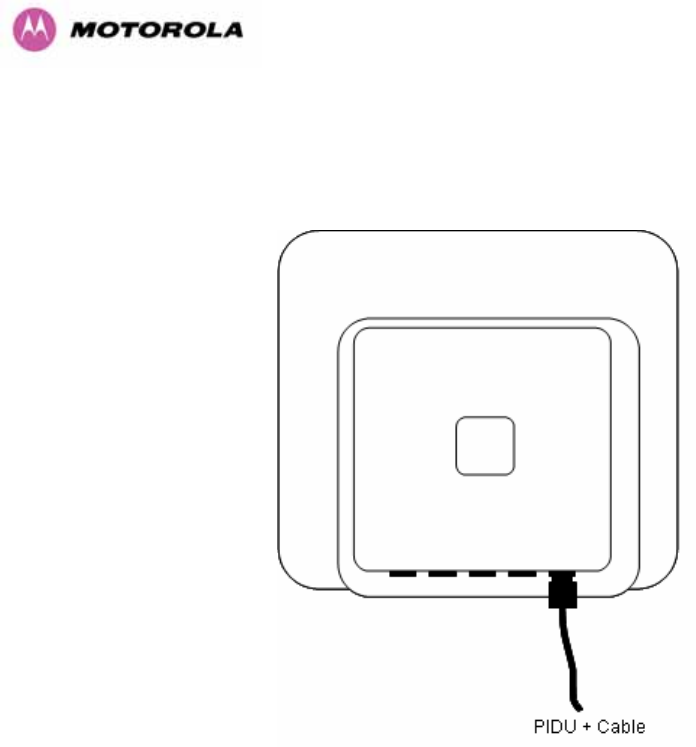
72
7.7.2 Making the Connections at the ODU
Looking at the back of the unit with the cable entry at the bottom, the PTP 600 Series Bridge
PIDU Plus connection is the first hole on the right (1034HFigure 31) and is labeled “PIDU +”.
Figure 31 – PTP 600 Series Bridge PIDU Plus Connection
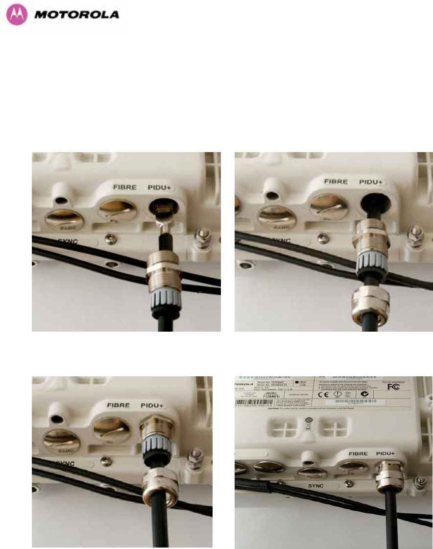
73
7.7.3 Making the PTP 600 Series Bridge PIDU Plus Connection At The ODU
The following procedure describes how connection is made at the ODU. It is often easier to
carry out this procedure on the ground or a suitable surface prior to mounting the ODU.
Ensure that no power is connected to the PIDU Plus or present on the cable before
connecting the ODU.
Step 1: Assemble the cable as described in
5.7.1 above
Step 2: Insert the RJ45 connector making
sure that the locking tab snaps home
Step 3: Screw in the body of the weather
proofing gland and tighten
Step 4: Screw on the clamping nut and tighten

74
Should it be necessary to disconnect the PIDU Plus to ODU cable at the ODU, this can be
achieved by removing the weather proofing gland and depressing the RJ45 locking tab with a
small screwdriver as shown below:
Figure 32 - Disconnecting the ODU
Warning: Ensure that power is removed from the system at the PIDU Plus to prevent damage
to the ODU while making or breaking the connection.
7.7.4 Routing the Cable
After connecting the cable to the ODU it can be routed and secured using standard cable
routing and securing techniques. When the cable is in place it can then be cut to the desired
length at the PIDU Plus prior to connection to the PIDU Plus
7.7.5 Fitting A Surge Arrestor
If you have opted to fit a Surge Arrestor, this should be installed by following the
manufacturer’s instruction. For recommended types see Section 1035H11 “Lightning Protection”
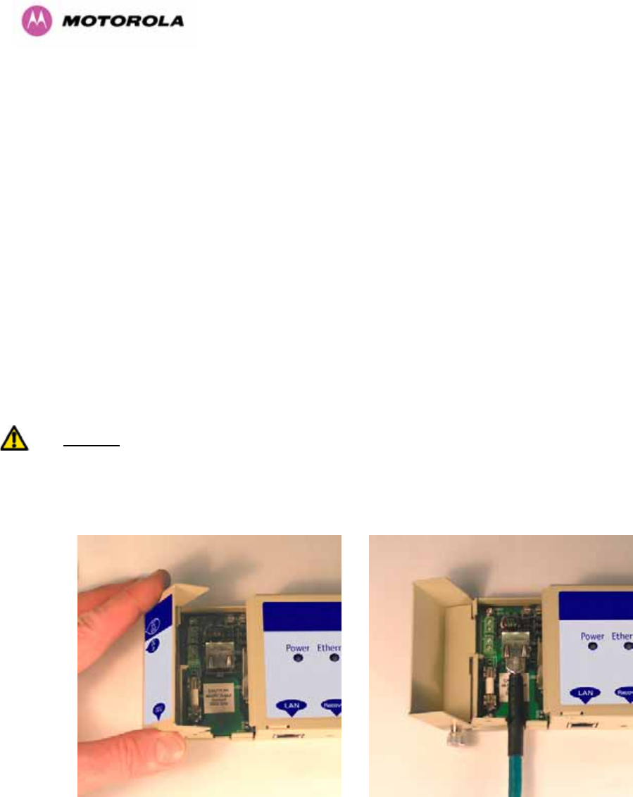
75
7.7.6 Grounding the Installation
The Outdoor Unit (ODU) must be properly grounded to protect against power surges. It is the
user’s responsibility to install the equipment in accordance with Section 810 of the National
Electric Code, ANSI/NFPA No.70-1984 or Section 54 of the Canadian Electrical Code or the
National Electrical Code in the country of installation. These codes describe correct
installation procedures for grounding the outdoor unit, mast, lead-in wire and discharge unit,
size of grounding conductors and connection requirements for grounding electrodes. It is
recommended that installation of the outdoor unit be contracted to a professional installer.
See Section 1036H11 “Lightning Protection” for recommended grounding kits”.
7.7.7 Making the ODU Connection at the PTP 600 Series Bridge PIDU Plus
The ODU is connected to the PIDU Plus by means of a concealed RJ45 connector. The RJ45
connection has been placed inside the PIDU Plus hinged cover to prevent the user from
inadvertently plugging other equipment into the ODU RJ45 socket.
Warning: Plugging other equipment into the ODU RJ45 socket may damage the equipment
due to the non-standard techniques employed to inject DC power into the 1000BaseT
connection between the PIDU Plus and the ODU. Plugging the ODU into other equipment
may damage the ODU and/or the other equipment.
Step 1: Undo the retaining screw and hinge
back the cover.
Step 2: Plug in the ODU into the PIDU Plus
Cable ensuring that it snaps home
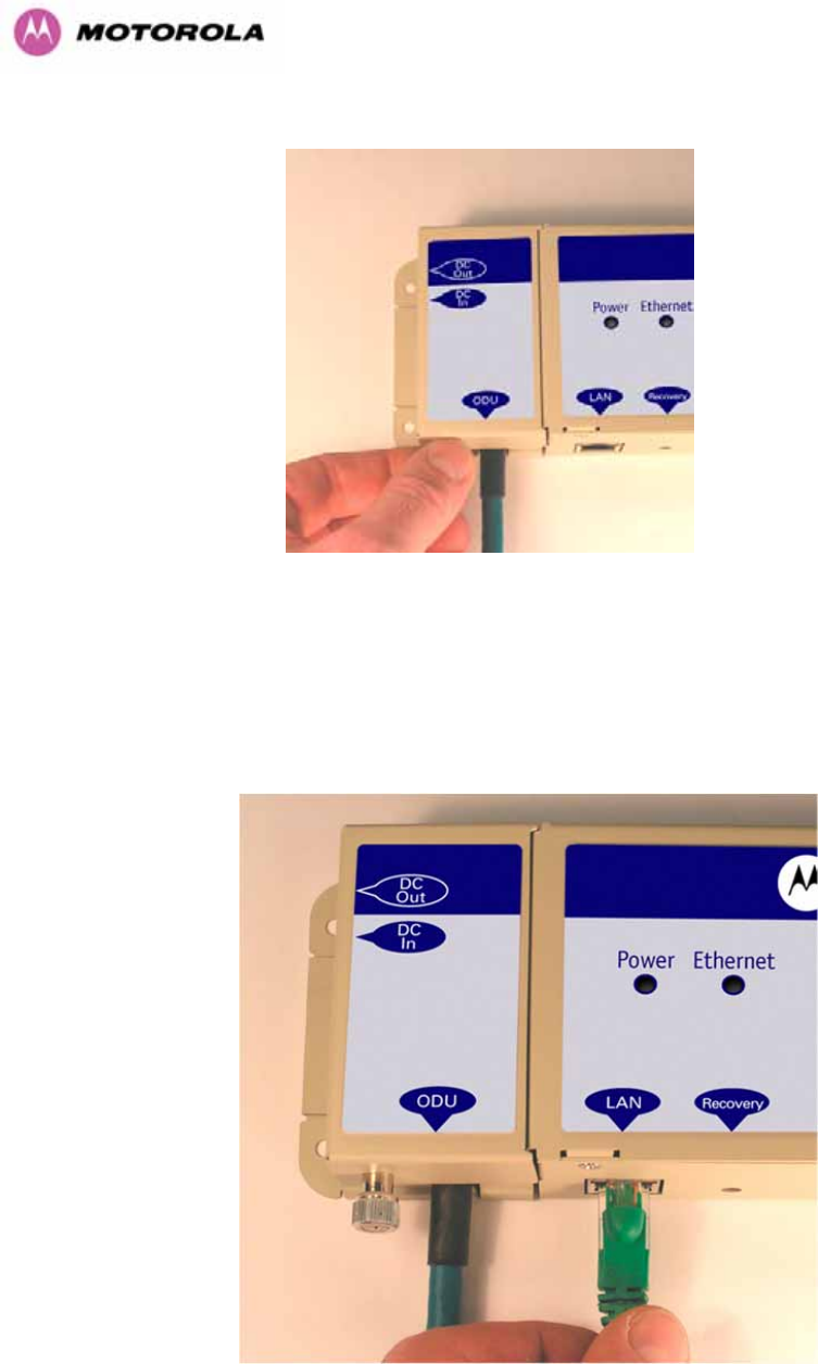
76
Step 3: Replace the cover and secure with the retaining screw
7.7.8 Making the Network Connection at The PIDU Plus – PTP 600 Series Bridge
The Network connection is made by connecting the user’s Network Equipment directly to the
PIDU Plus LAN port as shown in 1037HFigure 33.
Figure 33 - Making the Network Connection at the PIDU Plus
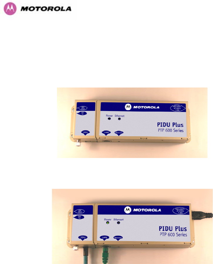
77
7.7.9 Mounting the PTP 600 Series Bridge PIDU Plus
This step is optional. Motorola recommends that you mount the PIDU Plus on a wall or other
suitable mounting surface. This prevents the unit from being knocked or kicked and can help
maintain link availability. Ensure that the reset switch can be accessed when mounting the
unit.
Step 1: Fix the PIDU Plus to the wall using the lugs provided.
Step 2: Make connections as per Section 1038H5.7.7
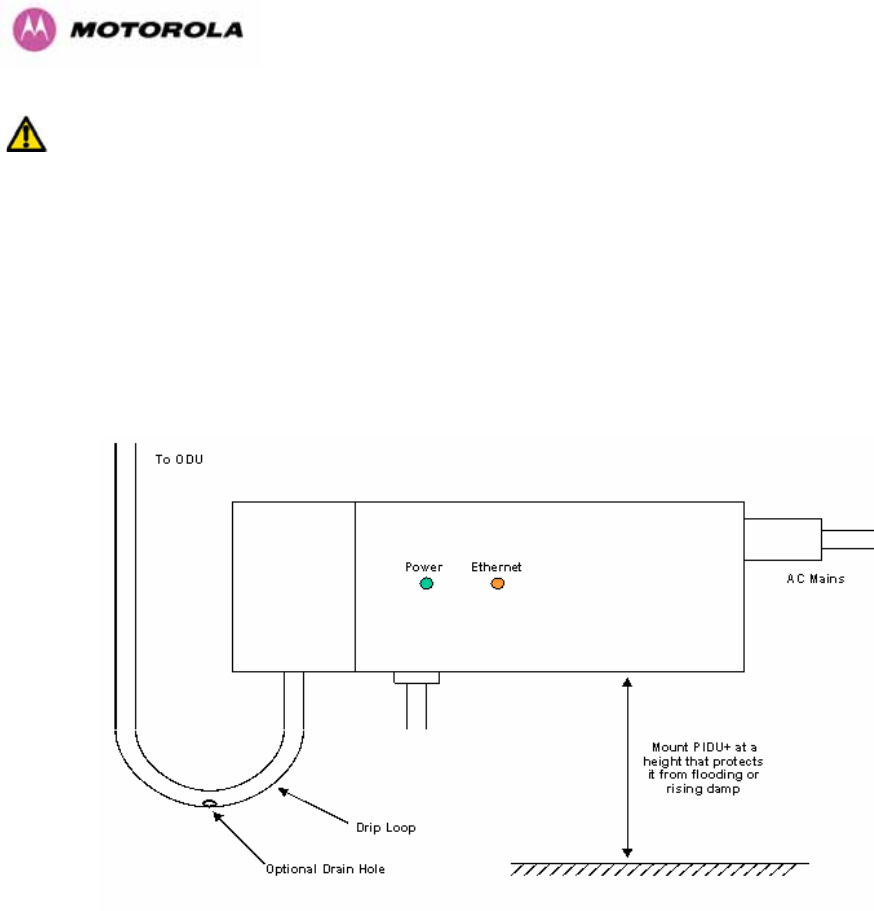
78
WARNING: The PIDU Plus is not waterproof and should be mounted away from sources of
moisture. If mounted outdoors, the unit should be mounted in a rain proof enclosure,
preferably ventilated.
It is also recommended that you fit a drip loop on the PIDU Plus to ODU cable to ensure that
any moisture that runs down the cable into the cabinet or enclosure cannot enter the PIDU
Plus. As shown in 1039HFigure 34. The network connection and mains cable should be treated in
the same way if there is a risk that they can carry moisture to the PIDU Plus.
Figure 34 – PTP 600 Series PIDU Plus Drip Loop Configuration

79
WARNING: It is possible for moisture to enter the cable due to damage to the outer protective
layer. This moisture can track down the inside of the cable, filling up the drip loop and
eventually finding its way into the PIDU Plus. To protect against this the outer protective layer
of the cable can be opened up at the bottom of the drip loop to allow this moisture to escape.
WARNING: Some network operators employ gel filled cables to get around the problem of
moisture ingress and transmission. The PTP 600 Series Bridge has NOT been tested against
these cables. Use of gel filled cables may affect the performance of PTP 600 Series bridge.
7.7.10 Powering Up
The PTP 600 Series Bridge is supplied as a pair of matched Master/Slave units. The Master
unit can now be powered up and accessed using the default URL 476Hhttp://169.254.1.2/; the
Slave unit can be accessed using 477Hhttp://169.254.1.1/.
Prior to powering up the PTP 600 Series Bridge, a computer with web browsing capabilities
should be configured with an IP address of 169.254.n.n and subnet mask of 255.255.0.0
where n is any value between 1 and 254 but excluding 1.1 or 1.2. If the default addresses of
the unit 169.254.1.1/2 clashes with an address you are already using on your LAN, or you are
not sure, you should set up an isolated LAN. As the LAN connection presented at the PIDU
Plus has a default configuration as a hub/switch (and auto-sensing MDI/MDIX cross over is
employed), connection can be made directly to the computer using a standard CAT 5 patch
cable.
Before physical installation takes place the units to be installed should be set up as described
in the Section 1040H8.3.4. This process will give the installer the opportunity to set the unit’s IP
address to one that is in the desired address range and set each unit up with the MAC
address of its peer unit ready to establish a radio link. It is recommended that this procedure
be carried out on the bench before physical installation commences. Providing it is safe to do
so, the installer should take the process to the point where a radio link is established before
proceeding to the installation site.
NOTE: It is possible that some units may not be accessed using the above default URL. This
is because these units may have been previously configured with IP addresses 10.10.10.11
(Master) and 10.10.10.10 (Slave). Therefore, users must use the URL 478Hhttp://10.10.10.10/
and/or URL 479Hhttp://10.10.10.11/ to configure the units. Please ensure that a computer with web
browsing capabilities is configured with an IP address of 10.10.10.n, where n is any value
between 2 and 254 but excluding 10 and 11, to configure these units.

80
7.7.11 Aligning the PTP 600 Series Bridge ODUs
The following is a description of the steps taken to establish a radio link between the two
units forming the bridge and align the units for the best signal strength.
The PTP 600 Series Bridge uses audible tones during installation to assist the installer with
alignment. The installer should adjust the alignment of the ODU in both azimuth and elevation
until highest pitch tone is achieved10F
11. The tones and their meanings are as follows:
State Name Tone
Description State Description Pitch Indication (Higher
pitch = higher power)
Free Channel
Search
Regular beep Executing band scan N/A
Scanning Slow broken
tone
Not demodulating the wanted
signal
Rx Power
Synchronized Fast broken
tone
Demodulating the wanted
signal
Rx Power
Registered Solid tone Both Master and Slave units
exchanging Radio layer MAC
management messages
Rx Power
Table 13 - Audio indications from the ODU
The term ‘wanted signal’ refers to that of the peer unit being installed.
In each of the states detailed above, the unit should be aligned to give the highest pitch tone.
It should be noted that if, when in the Synchronized or Registered state, the tone varies
wildly, you may be suffering from interference or a fast fading link. Installing in this situation
may not give a reliable link. The cause of the problem should be investigated.
For the ease of alignment, both Master and Slave units use the install tones in the same way
but with some small behavioral differences. This allows the installer to install the Slave unit
first and carry out the initial alignment with the Master unit if desired. However, due to the
behavioral differences of Master and Slave units, it is recommended that the Master unit is
installed first and the initial alignment carried out at the Slave unit.
11 The pitch of the alignment tone is proportional to the received power of the wireless signals. The
best results are usually achieved by making small incremental movement in angular alignment.

81
The following behavior should be noted:
• When first started up and from time to time, the Master unit will carry out a band scan to
determine which channels are not in use. During this time, between 10 and 15 seconds,
the Master unit will not transmit and as a consequence of this neither will the Slave unit.
During this time the installation tone on the master unit will drop back to the band scan
state, and the Slave unit will drop back to the Scanning state with the pitch of the tone set
to the background noise level. Alignment of the unit should cease during this time.
• The master unit can take up to 60 seconds in 0-40km (0-25 miles) mode, 90 seconds in
0-130km (0-81 miles) mode and 120 seconds in 0-200km (0-124 miles) mode to
determine the range of the link being installed11F
12. The Master unit will remain in the
Scanning state until the range of the link has been established. The Master unit will only
move to the Synchronized state when the range of the link has been established.
• If, at the end of the ranging period, the Registered state is not achieved due to
interference or other reasons, the Master unit will retry twice more on the same channel
before moving to another available channel. Should this occur it might take a number of
minutes to establish a link in the Registered state.
• The Slave unit does not have a ranging process. The slave unit will change to the
Synchronized state as soon as the wanted signal is demodulated.
When the alignment process is complete the installer MUST REMEMBER TO DISARM BOTH
UNITS in the link as described in Section 1041H8.3.4. This is necessary in order to:
• Turn off the audible alignment aid
• Enable Adaptive Modulation
• Fully enable Advanced Spectrum Management with i-DFS
• Clear unwanted installation information from the various systems statistics
• Store the link range for fast link acquisition on link drop
• Enable higher data rates
12 If the unit is operating where mandatory radar avoidance algorithms are implemented the ranging
behaviour for the PTP 600 Series Bridge may be affected. The Master has to monitor the initially
chosen channel for 60 seconds to make sure it is clear of radar signals before transmitting. If a radar
is detected during any of the installation phases a further compulsory 60 seconds channel scan will
take place as the master unit attempts to locate a new channel that is free of radar interference

82
8 Web Page Reference
The web user interface has three main sections. The home page presents to the operator a
high level summary of the PTP 600 Series Bridge point-to-point wireless link. The status page
presents a more detailed set of system parameters describing the performance of the
wireless link together with other key system performance metrics. The final section is the
system administration section. This section is password protected and allows the system
administrator to perform all the day-to-day administrative procedures, e.g. software upgrade
and performing configuration changes.
The following subsections give a detailed usage guide for all the web user interfaces.
The web pages are best viewed using a screen resolution of at least 1024 x 768 pixels on a
PC using Microsoft Internet Explorer Version 612F
13.
13 The web pages have also been tested with Firefox 1.0.6. Other browsers may function correctly but
have not been tested.
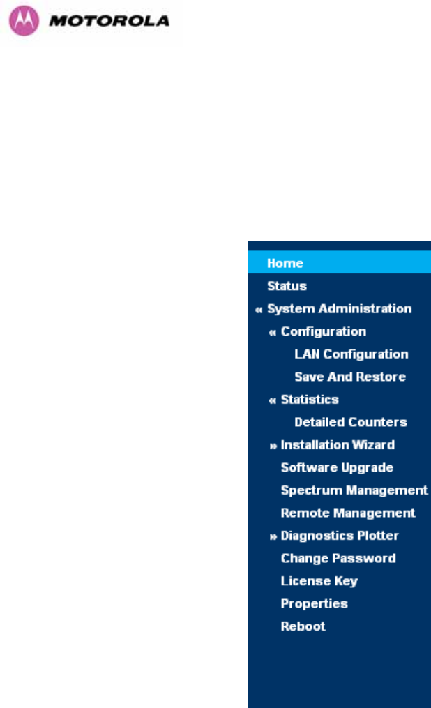
83
The navigation bar on the left hand side of the web page is used to move between the various
management pages. The currently selected page is always highlighted with a dark blue
background. The menu is hierarchical. Selecting a menu item which has associated submenu
options will automatically display all sub options. A sample web page with the navigation
menu is shown in 1042HFigure 35 when the ‘Home’ Link is highlighted as the current page.
Figure 35 - Menu Navigation Bar
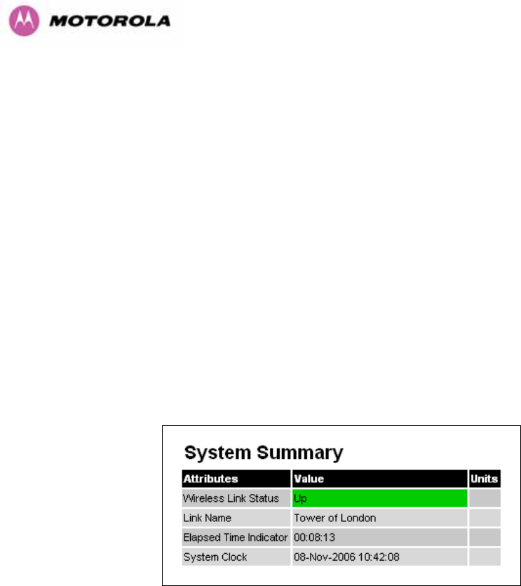
84
8.1 Home Page – PTP 600 Series Bridge
The home page for the PTP 600 Series Bridge has been designed to display a high level
summary of the status of the wireless link and associated equipment. The home page (1043HFigure
36) normally displays four key system attributes:
Wireless Link Status: The Wireless Link Status attribute displays the current status of the
PTP 600 Series Bridge wireless link. A state of ‘Up’ on a green background indicates that a
point-to-point link is established. A state of ‘Down’ on a red background indicates that the
wireless link is not established. If the link is down for an unknown reason the system
administrator should first consult the status web page for a more detailed summary of up to
date system diagnostics.
Link Name: The link name attribute is a name and/or handle allocated by the system
administrator to aid the identification of the unit, network or building.
Figure 36 - System Summary Page
Elapsed Time Indicator: The elapsed time indicator attribute presents the total time in days,
hours, minutes and seconds since the last system restart. The system can restart for several
reasons, e.g., commanded reboot from the system reboot webpage, or a power cycle of the
equipment.
System Clock: If SNTP (Simple Network Time Protocol) is enabled, or the clock has been
set, then a system clock attribute is displayed giving the date and time of the last page
refresh. Section 1044H8.3.11.6 explains how to enable SNTP and Section 1045H8.3.11.7 explains how to
set the clock.
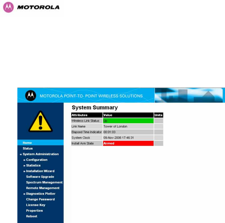
85
8.1.1 Home Page Alarm Display
The home page is also used to display all outstanding major system alarms. Whenever
system alarms are asserted, a yellow warning triangle is displayed on web page navigation
bar. The warning triangle will be visible from all web pages. Clicking the warning triangle will
cause the web page to jump back to the system homepage. 1046HFigure 37 shows a sample alarm
screen.
Figure 37 - Alarm Warning Triangle
The following major system alarms are defined:
Install Arm State: The Install Arm State alarm is displayed. This alarm warns when a
wireless unit is in installation mode. After installation the wireless unit should be disarmed.
This will increase the wireless link’s data-carrying capacity and stop the installation tone
generator. The wireless link is disarmed from the ‘Installation Wizard’ see Section 1047H8.3.4.

86
Install Status: If any errors are detected during the installation process, the unit will
automatically raise an audible alarm. The install status alarm will be raised with an
appropriate reason code, e.g. the alarm will be raised if an incorrect target MAC address is
specified for the peer 600 Series Bridge.
Ethernet Link Status: If there are any problems with the Ethernet interface, this alarm will be
asserted. This alarm will most likely be seen if the unit has no Ethernet cable plugged into its
Ethernet socket.
Master And Slave Have Incompatible Region Codes: The 600 Series bridge uses region
codes to comply with local regulatory requirements governing the transmission of wireless
signals in the 5.8 and 5.4 GHz bands. Region codes can only be changed by obtaining a new
PTP 600 Series license key. If this alarm is encountered the appropriate license keys from the
country of operation should be obtained from your distributor. Applying license keys
containing the same region codes to both ends of the link will remove the alarm.
Spectrum Management Channel Warning: This alarm warns the user when the intelligent
spectrum management feature can't find a suitable wireless channel.
Hardware Authentication Alarm: If the Hardware Authentication Alarm is displayed on the
front page please contact Motorola Customer support for further assistance.
Ethernet Link Disable Warning: This warning is displayed if the Ethernet link has been
administratively disabled via the SNMP Interface. The Ethernet Interface MIB-II ifAdminStatus
attribute has been set to DOWN. To enable the Ethernet interface, set the ifAdminStatus
attribute to UP.
Wireless Link Disabled Warning: This warning is displayed if the Wireless link has been
administratively disabled via the SNMP Interface. The Wireless Interface MIB-II ifAdminStatus
attribute has been set to DOWN. To enable the Ethernet interface, set the ifAdminStatus
attribute to UP.
Fiber Link Disabled Warning: This warning is displayed if an SFP is installed but has been
disabled because your license key does not include fiber support.
Ethernet Configuration Mismatch Alarm: This warning is an indication that Ethernet
fragments are being detected on the Ethernet port. This is an indication of an auto negotiation
or forced Ethernet configuration mismatch.
SNTP No Sync Warning: This warning indicates that SNTP has been enabled but that the
unit is unable to synchronize with the specified SNTP server. Section 1048H6.3.9.5 explains how to
configure SNTP.

87
Telecoms Channel A Status: Indicates that there is a problem with the telecoms channel A.
Possible problems are "No Signal (local)", "No Signal (Remote)", and "No Signal (Local and
Remote)".
Telecoms Channel B Status: Indicates that there is a problem with the telecoms channel B.
Possible problems are "No Signal (local)", "No Signal (Remote)", and "No Signal (Local and
Remote)".
Telecoms Interface A Loopback: The telecoms loopback features are intended for
installation testing only and should be set to 'None' for normal operation. The loopback can be
disabled from the telecoms configuration sub menu (see Section 1049H8.3.1.6).
Telecoms Interface B Loopback: The telecoms loopback features are intended for
installation testing only and should be set to 'None' for normal operation. The loopback can be
disabled from the telecoms configuration sub menu (see Section 1050H8.3.1.6).
Incompatible Master and Slave: This warning is displayed when the master and slave ends
of the wireless link have incompatible configurations. The two possible scenarios for seeing
this warning are:
1. "Incompatible Master and Slave product variants". The product variant is controlled by the
unit’s license key. Check that the correct set of compatible license keys have been
inserted into the units.
2. "Master and Slave are running different software versions". Check the software versions
on each end of the wireless link and upgrade one or both of the software versions to
remedy the incompatibility.
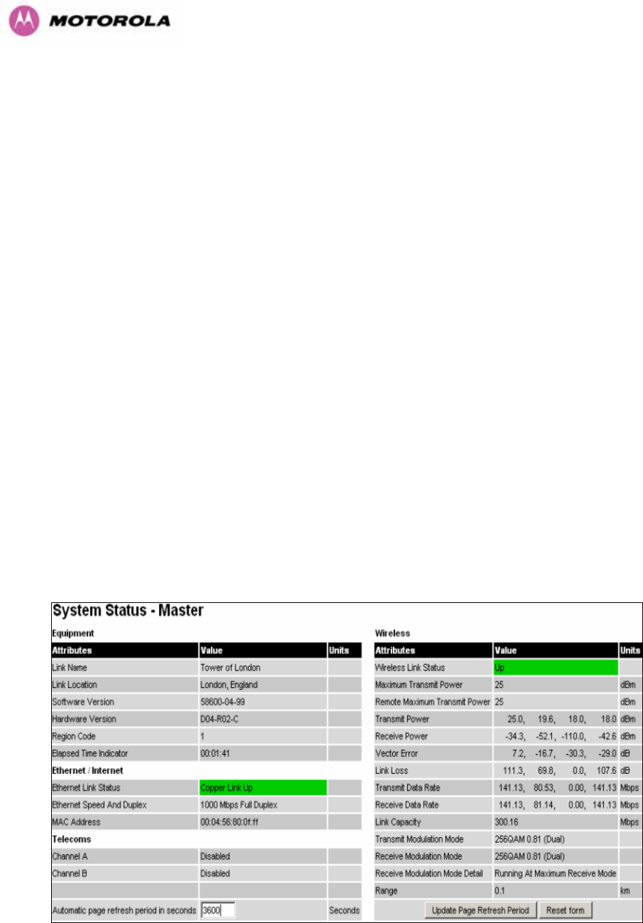
88
8.2 Systems Status Page
The status page has been designed to give the system administrator a detailed view of the
operation of the 600 Series Bridge from both the wireless and network perspectives.
The page is subdivided into three main categories Equipment, Wireless, Telecoms and
Ethernet/Internet. The ‘Equipment’ section contains the unit’s inventory and identification
information. The ‘Wireless’ section presents the key wireless metrics, which are displayed as
a series of measurements and histograms. The ‘Ethernet/Internet’ section describes the unit’s
network identity and connectivity. “Telecoms” controls the unit’s E1/T1 telecoms interfaces.
The status page can be configured to refresh itself at an operator defined rate (if the user is
logged in as system administrator). The refresh period defaults to 3600 seconds and can
easily be changed to refresh at any period between 3 seconds and 3600 seconds. Pressing
the ‘Update Page Refresh Period’ button causes a new page refresh period to be adopted by
the system. The page refresh mechanism uses a HTML Meta refresh command. Therefore
the refresh is always initiated by the local browser and not by the 600 Series Bridge at this
interval.
The two PTP 600 Series bridges units are arranged in a master and slave relationship. The
roles of the units in this relationship are displayed in the page title. The master unit will always
have the title ‘- Master’, and the slave will always have ‘- Slave’ appended to the ‘Systems
Status’ page title.
Figure 38 - Status Page

89
The following section details all the attributes displayed on the status page:
Link Name: The link name is allocated by the system administrator and is used to identify the
equipment on the network. The link name attribute is limited to a maximum size of 63 ASCII
characters.
Link Location: The link location is allocated by the system administrator and can be used as
a generic scratch pad to describe the location of the equipment or any other equipment
related notes. The link location attribute is limited to a maximum size of 63 ASCII characters.
Software Version: The attribute describes the version of software installed on the
equipment. The format of the attributes is FFSSS-XX-YY where FF is the frequency variant
(2.5, 5.4 or 5.8GHz), SSS is the System Release, XX is the major release version and YY is
the minor release version.
Hardware Version: The hardware version attribute contains all the combined hardware
version information. The attribute is formatted as DXX-RYY-Z where DXX contain the version
of the digital card, RYY contains the version of the RF (radio frequency) card and Z describes
the antenna type which can be I (integrated) or C (connectorized).
Region Code: The region code is used by the system to constrain the wireless to operate
within regulatory regime of the particular country. The region code is encoded in the product
license key. If the operator wishes to change region code, a new license key must be
obtained from Motorola or the local point-to-point distributor / system integrator.
Elapsed Time Indicator: The elapsed time indicator attribute presents the total time in years,
days, hours, minutes and seconds since the last system restart. The system can restart for
several reasons, e.g. commanded reboot from the system reboot web page, or a power cycle
of the equipment.
Ethernet Link Status: Current status of the Ethernet link. A state of ‘Up’ with a green
background indicates that an Ethernet link is established. A state of ‘Down’ with a red
background indicates that the Ethernet link is not established.

90
Ethernet Speed and Duplex: The negotiated speed and duplex setting of the Ethernet
interface. The speed setting is specified in Mbps. Full Duplex data transmission means that
data can be transmitted in both directions on a signal carrier at the same time. For example,
on a local area network with a technology that has full duplex transmission; one workstation
can be sending data on the line while another workstation is receiving data. Half Duplex data
transmission means that data can be transmitted in both directions on a signal carrier, but not
at the same time. For example, on a local area network using a technology that has half
duplex transmission, one workstation can send data on the line and then immediately receive
data on the line from the same direction in which data was just transmitted.
Channel A: The status of telecom interface A.
Channel B: The status of telecom interface B.
Wireless Link Status: As the attribute name suggests it displays the current status of the
wireless link. A state of ‘Up’ on a green background indicates that a point-to-point link is
established. A state of ‘Down’ on a red background indicates that the wireless link is not
established.
Maximum Transmit Power: The maximum transmit power that the local wireless unit is
permitted to use to sustain a link.
Remote Maximum Transmit Power: The maximum transmit power that the remote wireless
unit is permitted to use to sustain a link.
Transmit Power: Transmit power histogram13F
14 is expressed in dBm and presented as: max,
mean, min, and latest. The max, min and latest are true instantaneous measurements; the
mean is the mean of a set of one second means.
Receive Power: Receive power histogram is expressed in dBm and presented as: max,
mean, min, and latest. The max, min and latest are true instantaneous measurements; the
mean is the mean of a set of one second means. See note 1051H14.
14 All histograms are calculated over a one hour period. If the equipment has been running for less
than one hour then the histograms are calculated over the current elapsed time.
The data used to compute the histogram statistics can be downloaded in an ASCII comma separated
value (CSV) format via the diagnostics CSV Download page, see Section 8.3.12.2.

91
Vector Error: The vector error measurement compares the received signal’s In phase /
Quadrature (IQ) modulation characteristics to an ideal signal to determine the composite error
vector magnitude. The results are stored in a histogram and expressed in dB and presented
as: max, mean, min and latest. The max, min and latest are true instantaneous
measurements; the mean is the mean of a set of one second means. The expected range for
Vector Error would be approximately -2dB (NLOS link operating at sensitivity limit on BPSK
0.67) to –33dB (short LOS link running 256 QAM 0.83). See note 1052H14.
Link Loss: The link loss is the total attenuation of the wireless signal between the two
point-to-point units. See note 1053H14.
The link loss calculation presented below:
xxxx RTRTll ggPPP
+
+
−
=
Where
ll
P Link Loss (dB)
x
T
P
Transmit power of the remote
wireless unit (dBm)
x
R
P
Received signal power at the local
unit (dBm)
xx RT gg ,
Antenna gain at the remote and local
units respectively (dBi). The antenna
gain of the 600 Series bridge (23.5
dBi) is used unless one or both of
the Gemini units is a Connectorized
version. See Section 11.3 for more
details
Equation 2 - Link Loss

92
Transmit Data Rate: The data rate in the transmit direction, expressed in Mbps and
presented as: max, mean, min, and latest histogram format. The max, min and latest are true
instantaneous measurements; the mean is the mean of a set of one second means.
See note 1054H14. Expected data rates can be found in Section 1055H4.1.4 “1056HAggregate Ethernet
throughput rate v maximum link loss”.
Receive Data Rate: The data rate in the receive direction, expressed in Mbps and presented
as: max, mean, min, and latest histogram format. The max, min and latest are true
instantaneous measurements; the mean is the mean of a set of one second means.
See note 1057H14. Expected data rates can be found in Section 1058H6.1.5.
Link Capacity: The maximum aggregate data rate capacity available for user traffic,
assuming the units have been connected using Gigabit Ethernet. The link capacity is variable
and depends of the prevailing wireless conditions as well as the distance (range) between the
two wireless units. When the link is idle and in ‘IP Mode’ the wireless link will adaptively
configure itself into a lower latency mode, this will cause the displayed link capacity and
aggregate data rates to diverge. This is because the aggregate data rate displays the
instantaneous capacity of the wireless link not the maximum potential capacity of the link as
displayed by link capacity.
Transmit Modulation Mode: The modulation mode currently being used on the transmit
channel. Details on the modulation modes can be found in Section 1059H23.1 “System
Specifications”.
Receive Modulation Mode: The modulation mode currently being used on the receive
channel. Details on the modulation modes can be found in Section 1060H23.1 “System
Specifications”.
Receive Modulation Mode Detail: This supplies the user with information regarding the
receive modulation mode in use. Possible values are:
• Running at maximum receive mode
• Running at user-configured Max Modulation Mode
• Restricted due to byte errors on the wireless link or local Ethernet Tx Fifo Drops
• Restricted because a DFS channel change is in progress
• Restricted due to telecoms acquisition mode
• Restricted due to the low Ethernet link speed
• Limited by the wireless conditions
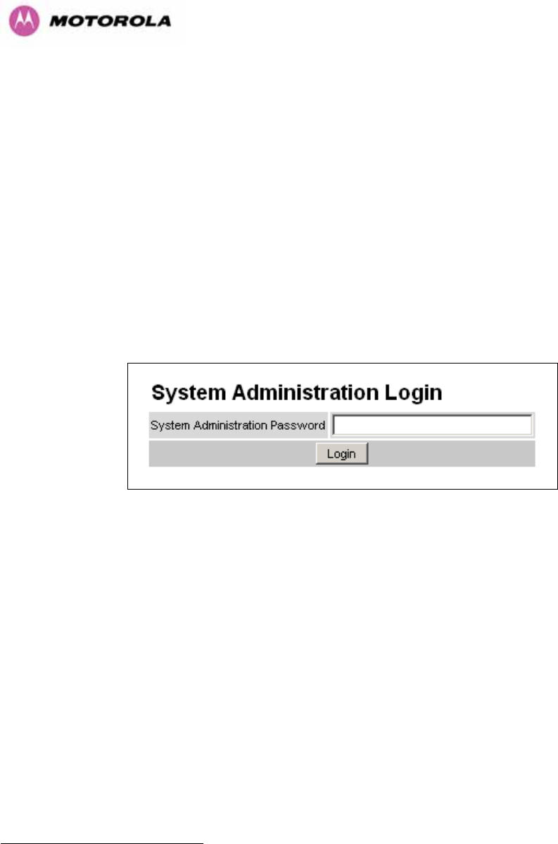
93
Range: The range14F
15 between the 600 Series bridge ODUs.
Refresh Page Period: The Status page refreshes automatically according to the setting
entered here (in seconds). This attribute is only displayed when the user is logged on as
System Administrator.
8.3 System Administration Pages
The following menu options are available for the system administrator and can be password
protected. 1061HFigure 39 shows the system administration login page. By default a system
administrator password is not set. Simply click the login button to access the system
administration features.
Figure 39 - System Administration Login Page
Once the password has been set using the ‘Change Password’ menu item the system
administration pages will only be available after the user has entered the correct password.
15 The PTP 600 Series Bridge displays range in km by default, if the user would prefer to display
range using Miles the ‘Distance Units’ attribute should be set to imperial, see the “Properties” web
page Section 8.3.15.

94
The features that are only available to the system administrator are:
• Configuration
• Statistics
• The Installation Wizard
• Software Upgrade
• Spectrum Management including DFS
• Remote management
• Diagnostics Plotter
• Password Management
• License Key Management
• Properties
• System Reboot
8.3.1 System Configuration
The configuration of the 600 Series Bridge is organized into three sections:
• General configuration
• LAN configuration
• Telecoms Configuration
• Save and Restore
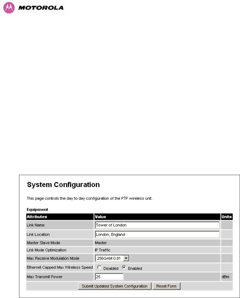
95
The general configuration allows modification of high level administrative (descriptive)
attributes and high level wireless configuration.
The LAN configuration sub menu allows the system administrator to modify the Ethernet and
IP configuration of the 600 Series Bridge.
The telecoms submenu displays the current status of the telecoms interface and allows the
configuration of interface loopbacks.
The save and restore submenu allows the system administrator to backup and restore the
bridge configuration. It is recommended after a unit has been successfully installed; a copy of
the active configuration is taken and archived by the system administrator.
8.3.1.1 General Configuration Page
The general configuration page (1062HFigure 40) is used by the system administrator to configure
the 600 Series Bridge’s high level administrative (descriptive) attributes and high level
wireless configuration.
Figure 40 - System Configuration Page

96
While the majority of the system configuration is entered during installation and should never
require changing, this page offers the system administrator the ability to change the basic
system parameters for both the wireless and Ethernet components.
Link Name: User defined identity for the unit (max 63 characters).
Link Location: Can be used as a generic scratch pad to describe the location of the
equipment.
Max Receive Modulation Mode: This is the maximum mode the unit will use as its adaptive
modulation. The modulation modes available are specified in Section 1063H23.1 ”System
Specifications”.
By default the Max Receive Modulation Mode is the highest mode available.
For minimum error rates on TDM links the user should set the maximum modulation mode to
64QAM 0.75 at both ends of the link.
Ethernet Capped Max Wireless Speed: When enabled this option will cap the wireless
speed to a mode that the connected Ethernet connection can sustain.
Maximum Transmit Power: This specifies the maximum transmit power in dBm of the
system. It is country dependent and although the user can change this in 1dB steps, it will be
limited to that country’s regulations15F
16.
Why Reduce Transmit Power?
If the link losses are low and the link data rate and availability targets are being easily
achieved, the transmitted power level may be reduced with a consequent benefit to other
users of the band, .e.g. fixed satellite links.
16
In the UK there is a legal requirement to provide a minimum of 19dB of transmit power control
range. When the equipment is operating with a UK Licence Key, an additional facility is provided on
the configuration page that allows the transmitted power to be reduced by 19dB compared to the
maximum allowed with a simple single step control.
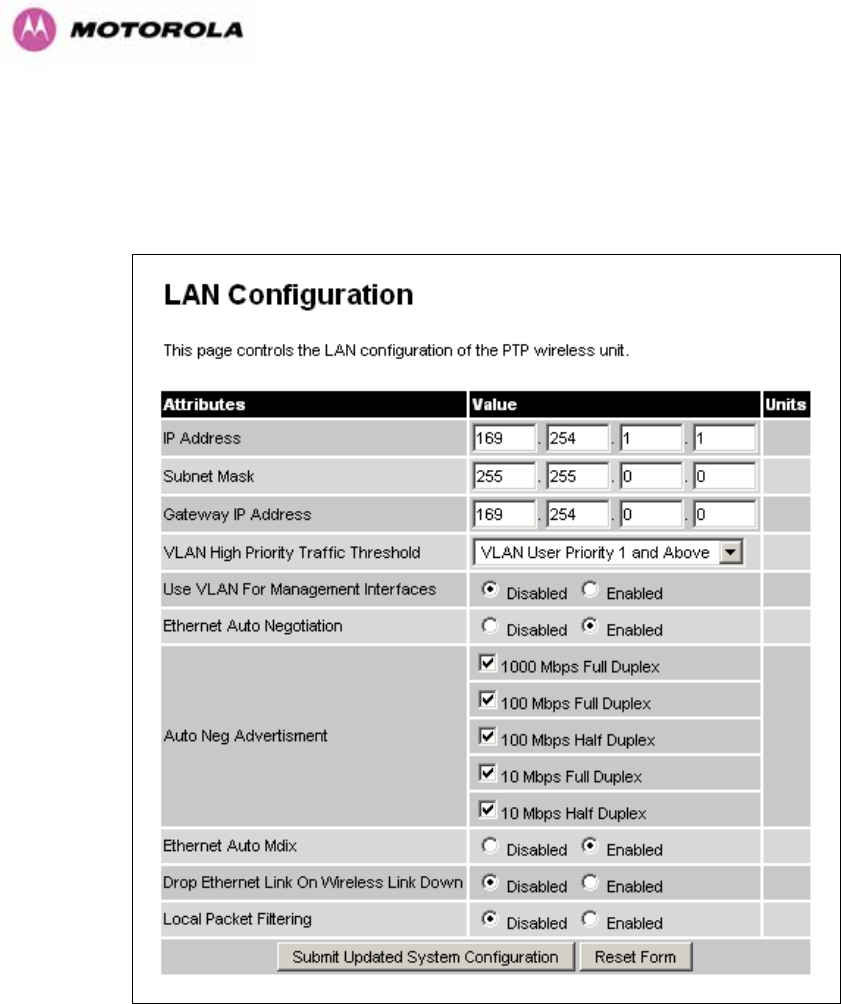
97
8.3.1.2 LAN Configuration Page
The LAN configuration page (1064HFigure 41) is used by the system administrator to configure the
600 Series Bridge’s LAN interface.
Figure 41 - LAN Configuration Page
IP Address: Internet protocol (IP) address. This address is used by the family of Internet
protocols to uniquely identify this unit on a network.
Subnet Mask: A subnet allows the flow of network traffic between hosts to be segregated
based on a network configuration.
Gateway IP Address: The IP address of a computer / router on the current network that acts
as a gateway.

98
VLAN High Priority Traffic Threshold: All packets with an 802.1P priority tag greater than
or equal to the indicated value will be treated as a high priority packet for transmission over
the wireless link.
Use VLAN For Management Interfaces: This controls whether the management interfaces
(WWW/SNMP/SMTP/SNTP) use 802.1Q VLAN tags or not. See Section 1065H8.3.1.3.
Ethernet Auto Negotiation This enables the Ethernet configuration to be forced rather than
auto negotiated.
Warning: The configuration should only be forced if you are having problems with auto
negotiation. You must ensure that you configure both this unit and the Ethernet port to
which it is connected identically. If you force a fixed Ethernet Configuration on the 600
Series bridge then you MUST also force the same fixed configuration on the equipment
to which it is connected. If you fail to force the configuration of the connected
equipment, its automatic configuration mechanisms will normally cause a duplex
mismatch, and you will receive greatly reduced throughput!
When Ethernet Auto Negotiation is Disabled the format of the LAN configuration page will
change see Section 1066H8.3.1.4 “1067HLAN Configuration Page – Manual Ethernet Configuration”.
Auto Neg Advertisement: This controls the rates that the auto negotiation mechanism will
advertise as available. Warning: Over the air throughput will be capped to the rate of the
Ethernet interface at the receiving end of the link.
Ethernet Auto Mdix: This enables/disables the Auto Medium Dependent Interface
(MDI)/Medium Dependent Interface Crossover (MDIX) capability.
Drop Ethernet Link On Wireless Link Down: When this option is enabled the Ethernet link
is momentarily dropped when the wireless link goes down. This feature is used to indicate to
the connected network equipment that this Ethernet link is no longer available, thus causing
STP (Spanning Tree Protocol) to re-route packets through an alternate link.
Local Packet Filtering: When Local Packet Filtering is “Enabled”, the bridge learns the
source MAC addresses of devices transmitting Ethernet packets on the local Ethernet
network, and only bridges packets to the remote unit if the destination MAC address has not
been learned as a 'local' device. When Local Packet Filtering is ‘Disabled’ the bridge does
not learn the source MAC addresses of devices transmitting Ethernet packets on the local
Ethernet network, and bridges ALL Ethernet packets received to the remote unit. Local
Packet Filtering should be disabled when external Ethernet switching hardware or a router is
present. The default setting for Local Packet Filtering is disabled.
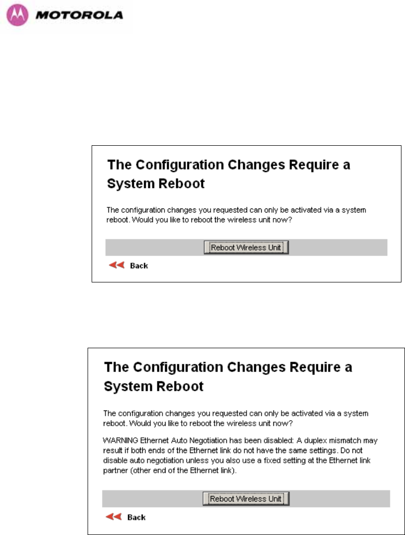
99
All of the above attributes are non-volatile, once set they will be used by the unit even after a
power on reboot. A number of attributes, such as IP Address, Subnet Mask and Gateway IP
Address and VLAN settings will require a reboot before they are used. If any of these
attributes are changed a reboot screen appears asking the user to verify the reboot (1068HFigure
42 or 1069HFigure 43).
Figure 42 - Configuration Reboot Page
Figure 43 - Configuration Reboot Page - Ethernet Auto Negotiation Disabled
This will be followed by a pop-up dialogue box asking to confirm the action.
Note: At this point you will lose connection to the unit. If you have just changed the IP
Address you now have to reconnect to the unit using the address just set.
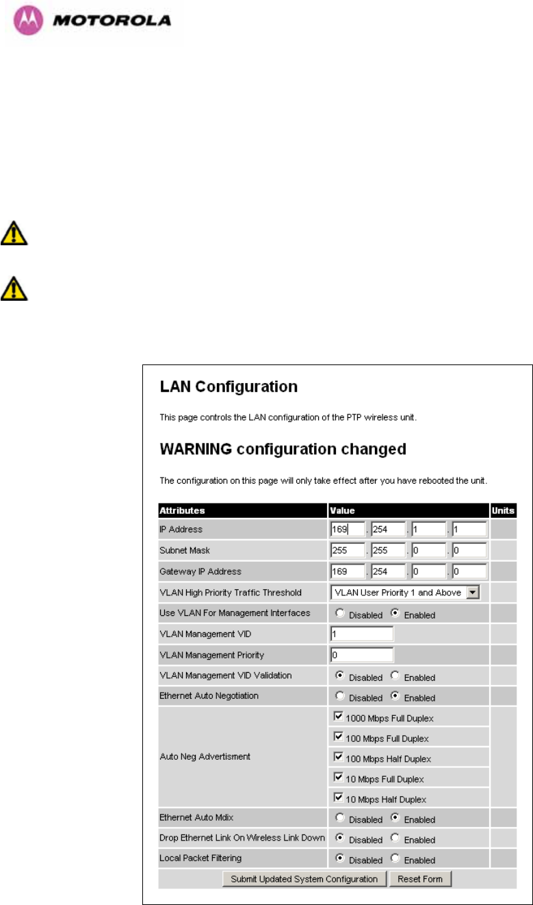
100
8.3.1.3 LAN Configuration Page – Use VLAN For Management Interfaces
The layout of the LAN Configuration page changes if this attribute is enabled in order to allow
the VLAN VID and VLAN Priority to be set, see 1070HFigure 441071H. The VLAN settings are applied only
after the unit is rebooted.
Warning: You must ensure that you can access the VLAN which you configure here,
otherwise you will be unable to access the unit following the next reboot.
Warning The PTP 600 is only compatible with single VLAN tagged packets. Any packet
with two or more packets will be ignored.
Figure 44 - VLAN Configuration Fields
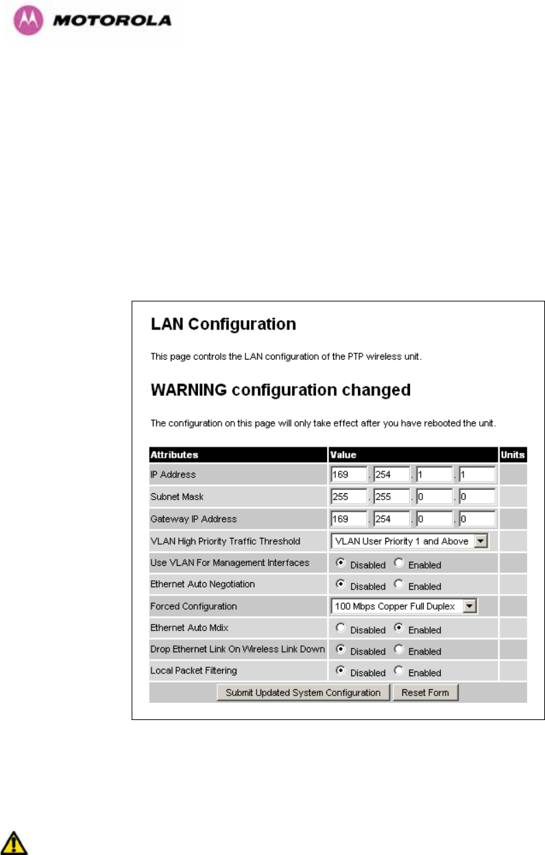
101
VLAN Management VID: This 802.1Q VLAN VID will be included in packets generated by
the management interfaces. Valid settings are in the range 0 to 4094.
VLAN Management Priority: This 802.1Q VLAN Priority will be included in packets
generated by the management interfaces. Valid settings are in the range 0 to 7.
VLAN Management VID Validation: If enabled, the management interfaces will only respond
to Ethernet packets tagged with the configured 802.1Q VLAN Management VID; otherwise
packets with any VID will be accepted.
8.3.1.4 LAN Configuration Page – Manual Ethernet Configuration
Figure 45 - LAN Configuration Page - Manual Ethernet Configuration
Force Configuration: This option allows the user to force the speed and duplex setting of the
Ethernet interface.
Warning: Over the air throughput will be capped to the rate of the Ethernet interface at
the receiving end of the link
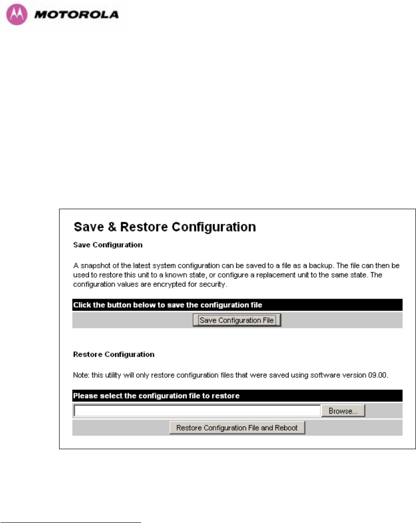
102
8.3.1.5 Save and Restore Configuration File
The save and restore feature of a PTP 600 Series Bridge allows the system administrator to
backup the operation configuration of the wireless unit. It is recommended that this facility is
used immediately after a successful PTP 600 Series Bridge installation or prior to any
software upgrade. In the unlikely event that a unit has to be replaced in the field, the
replacement unit can be reconfigured by simply playing back the saved configuration file.
To save the configuration file click on the ‘Save Configuration File’ button (1072HFigure 461073H) and
save the configuration file (.cfg) to the hard drive of your computer16F
17 17F
18.
Figure 46 - Save and Restore Configuration Page
17 There is a feature of Internet Explorer (all versions) that will always look at the content of any
downloadable file as make an assessment whether to treat the file as an ASCII or binary file.
Unfortunately the configuration file is always treated as ASCII and the browser attempts to display it
instead of downloading it. Firefox (all versions) makes no such assumptions.
18 The configuration file format is MAC-mm-mm-mm_IP-iii-iii-iii-iii.cfg where mm and iii are the lower 3
bytes of the MAC address and the unit IP address respectively.
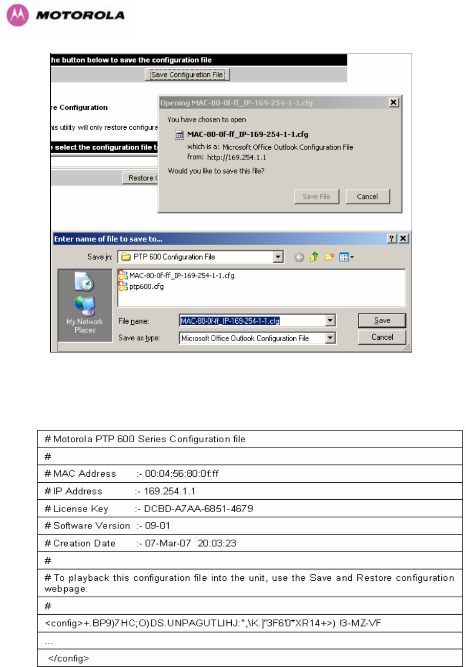
103
Figure 47 - Save Configuration File Screen
The configuration file is encoded using an ASCII encoding scheme. An example is show in
1074H1075HFigure 48.
Figure 48 – PTP 600 Example Configuration File
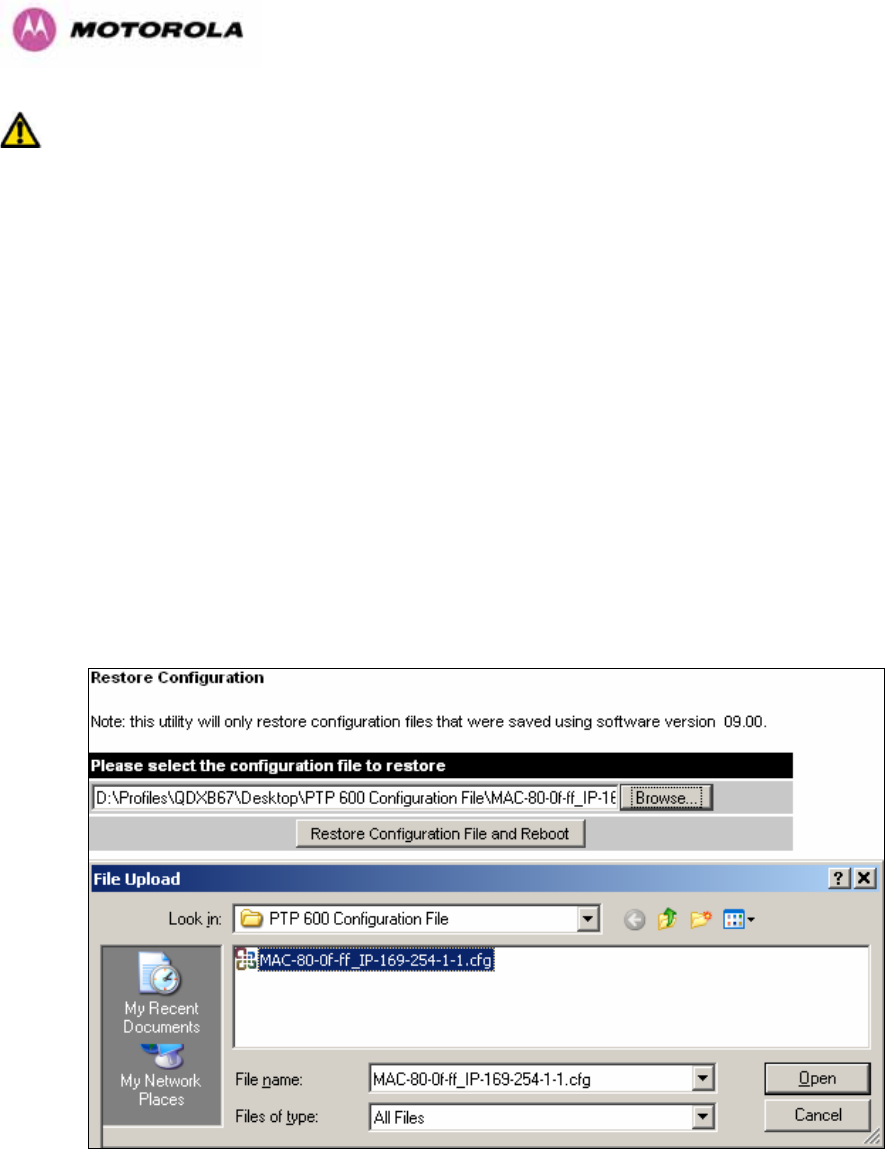
104
WARNING: The configuration file is currently restricted to a single software version and can
only be restored into a wireless unit operating the software version indicated in the
configuration file header.
The configuration file can also be used when swapping out a faulty wireless unit. If one of the
wireless units is replaced on a wireless link a configuration file captured from the faulty unit
can be replaced into the new unit to speed up replacement. It should be noted that when
placing a configuration file into a wireless unit with a different MAC Address the license key
will not be restored and may need to be entered. This can be obtained either from the Quick
Install guide supplied with replacement wireless unit or directly from Motorola. Note that the
target MAC address at the other hand needs to change.
The restoration of configuration files can be performed using the Restore configuration tool.
Using the browser button to locate the configuration file you wish to restore then click the
‘Restore Configuration File and Reboot’ button (1076HFigure 491077H). The user will then be prompted to
confirm the action (1078HFigure 50)
Figure 49 - Restore Configuration File Pop Up Screen
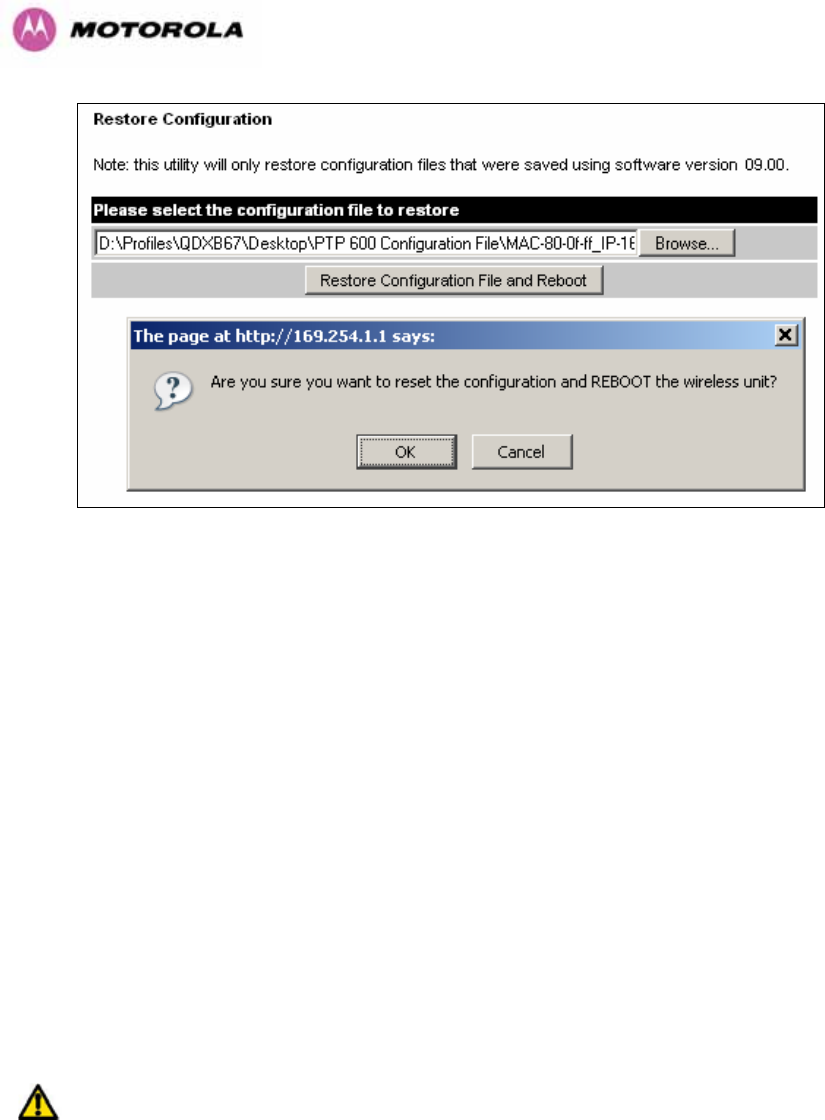
105
Figure 50 - Reset Configuration and Reboot Confirmation Pop-up
On confirmation the PTP 600 Series Bridge will:
• Upload the configuration file
• Perform data integrity checking
• Erase previous configuration
• Apply the new configuration
• Restart
After the unit has restarted the entire configuration from the configuration file will now be
active. Note: The IP address of the unit may have also been changed. The user can check
the new IP address by reading the header of the configuration file, 1079HFigure 48.
WARNING: A reboot is always required to restore a configuration file.
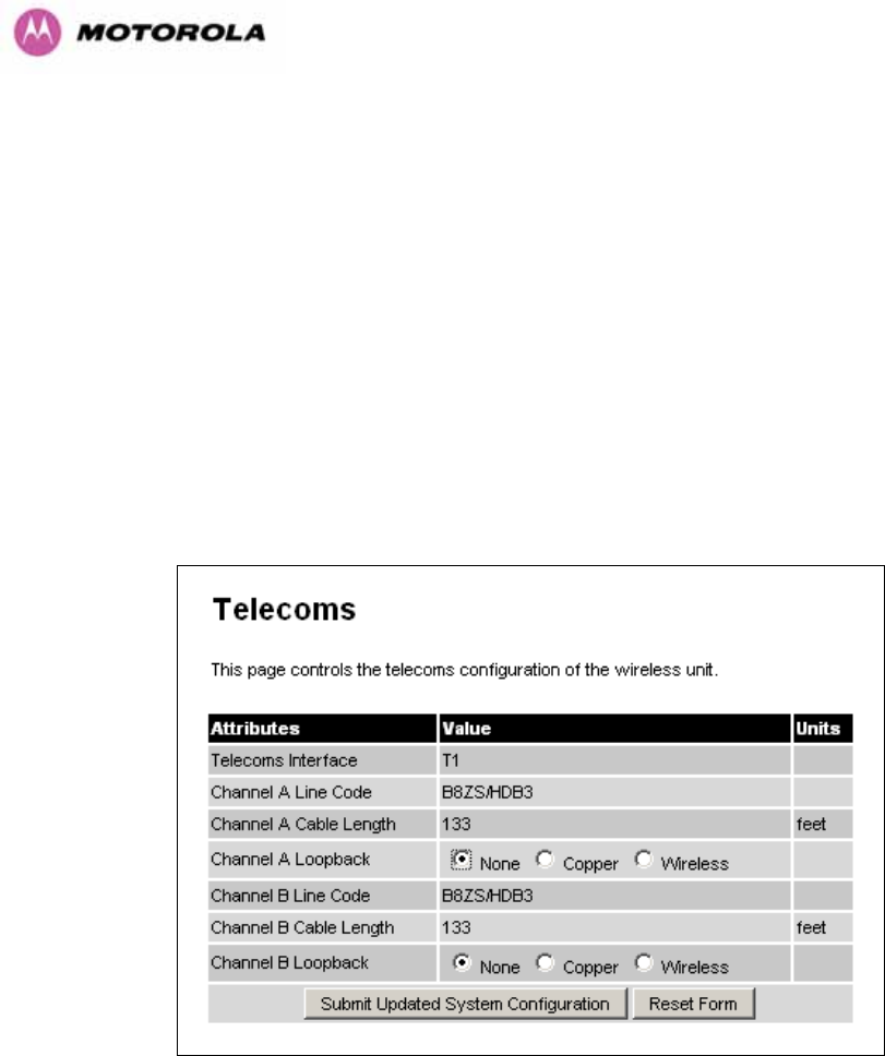
106
8.3.1.6 Telecoms Configuration Page
The Telecoms page is only available when the Telecoms Interface has been set to either T1
or E1 in the Installation Wizard.
It displays the interface setting and line code for the available telecoms channels. The PTP
600 Series Bridge is able to support two T1 or E1 channels. However, in the “Lite”
configuration one of these channels is disabled. The channels are referred to as "Channel A"
and "Channel B".
The "Channel B" configuration and controls will be displayed only when the second channel is
enabled.
Figure 51 - Telecoms Data Entry
Telecoms Interface: May be either T1, E1 reflecting the Installation Wizard setting.
Line Code: Displays the Line Code setting for each channel. The Line Code configuration
must match the configuration of the connected equipment and may be set using the
Installation Wizard.
Cable Length: The Cable Length setting is applicable in T1 mode only and shows the cable
length specified in the installation wizard.

107
Loopback: Allows the T1 or E1 data stream to be looped back at the copper or wireless
interface. During normal operation the loopback must be set to "None".
It may be helpful during installation to test the telecoms links by performing loopback
connections.
A "Copper" loopback connects the received data on a given telecoms interface to the
Transmit. A "Copper" loopback may be used, in conjunction with an appropriate test unit, to
confirm that the correct connections have been made to the ODU.
A "Wireless" loopback sends the telecoms data received across the wireless link back across
the link on the same channel. The link may be checked using, for example, a Bit Error Rate
Tester.
A typical T1 or E1 installation might include a "Copper" loopback on the local unit followed by
a "Wireless" loopback on the remote unit.
It is important to remove all loopbacks on channels for normal operation.
Alarms on the Home Page indicate the presence of loopbacks on either channel.
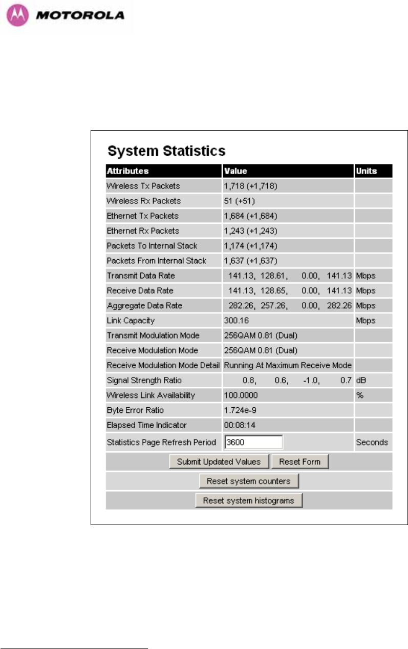
108
8.3.2 Statistics Page
The 600 Series bridge statistics page is designed to display some key statistics of the
Ethernet Bridge and the underlying wireless performance.
Figure 52 - System Statistics
Wireless Tx Packets: This displays the total number of good packets the bridge has sent for
transmission by the wireless interface18F
19.
Wireless Rx Packets: This displays the total number of good packets the bridge has
received from the wireless interface. See note 1080H19.
19 The number in (+nn) displays the number of packets received since the last page refresh.

109
Ethernet Tx Packets: This displays the total number of good packets the bridge has sent for
transmission by the local Ethernet interface. . See note 1081H19.
Ethernet Rx Packets: This displays the total number of good packets the bridge has
received from the local Ethernet interface. . See note See note 1082H19.
Packets To Internal Stack: This displays the total number of good packets the bridge has
transmitted to the internal stack (e.g., ARP requests, PING requests, HTTP requests). See
note 1083H19.
Packets From Internal Stack: This displays the total number of good packets the bridge has
received from the internal stack (e.g. ARP responses, PING replies, HTTP responses). See
note 1084H19.
Transmit Data Rate: The data rate in the transmit direction, expressed in Mbps and
presented as: max, mean, min, and latest histogram format. The max, min and latest are true
instantaneous measurements; the mean is the mean of a set of one second means. See Note
1085H14. Expected data rates can be found in Section 1086H6.1.5.
Receive Data Rate: The data rate in the receive direction, expressed in Mbps and presented
as: max, mean, min, and latest histogram format. The max, min and latest are true
instantaneous measurements; the mean is the mean of a set of one second means. . See
Note 1087H14. Expected data rates can be found in Section 1088H6.1.5.
Aggregate Data Rate: The sum of the data rate in the directions expressed in Mbps and
presented as: max, mean, min, and latest histogram format. The max, min and latest are true
instantaneous measurements; the mean is the mean of a set of one second means. See Note
1089H14. Expected data rates can be found in Section 1090H6.1.5.
Link Capacity: The maximum aggregate data capacity available for user traffic under the
current radio link conditions, assuming the units have been connected using Gigabit Ethernet.
The sum of the displayed Transmit and Receive data rates may be lower than this figure if the
link isn't fully loaded by the current traffic profile.
Transmit Modulation Mode: The modulation mode currently being used on the transmit
channel. The number in brackets after the modulation mode and coding rate string is the
effective data rate available to all MAC layer protocols. Details on the modulation modes can
be found in Section 1091H23.1 “System Specifications”.

110
Receive Modulation Mode: The modulation mode currently being used on the receive
channel. The number in brackets after the modulation mode and coding rate string is the
effective data rate available to all MAC layer protocols. Details on the modulation modes can
be found in Section 1092H23.1 “System Specifications”.
Receive Modulation Mode Detail: This supplies the user with information regarding the
receive modulation mode in use. Possible values are:
• Running at maximum receive mode
• Running at user-configured Target Modulation Mode
• Restricted because Installation is armed
• Restricted because of byte errors on the wireless link
• Restricted because a DFS channel change is in progress
• Restricted due to the low Ethernet link speed
• Limited by the radio conditions
Signal Strength Ratio: The Signal Strength Ratio is the ratio of the power received by the
Vertical / Horizontal receivers.
Wireless Link Availability: Expresses the link availability as a percentage of time since the
first successful registration after a system restart, expressed as a percentage to four decimal
places.
Byte Error Ratio: The ratio of detected Byte errors to the total number of bytes since the last
system reboot. This is a true measure of link quality as this measurement is made continually
using null frames when there is no user data to transport.
Statistics Page Refresh Period: The statistics page refreshes automatically according to the
setting entered here (in seconds).
Reset System Counters: By pressing this button all counters in the system are reset to zero.
Reset System Histograms: All histograms are reset, and the calculation period is restarted.
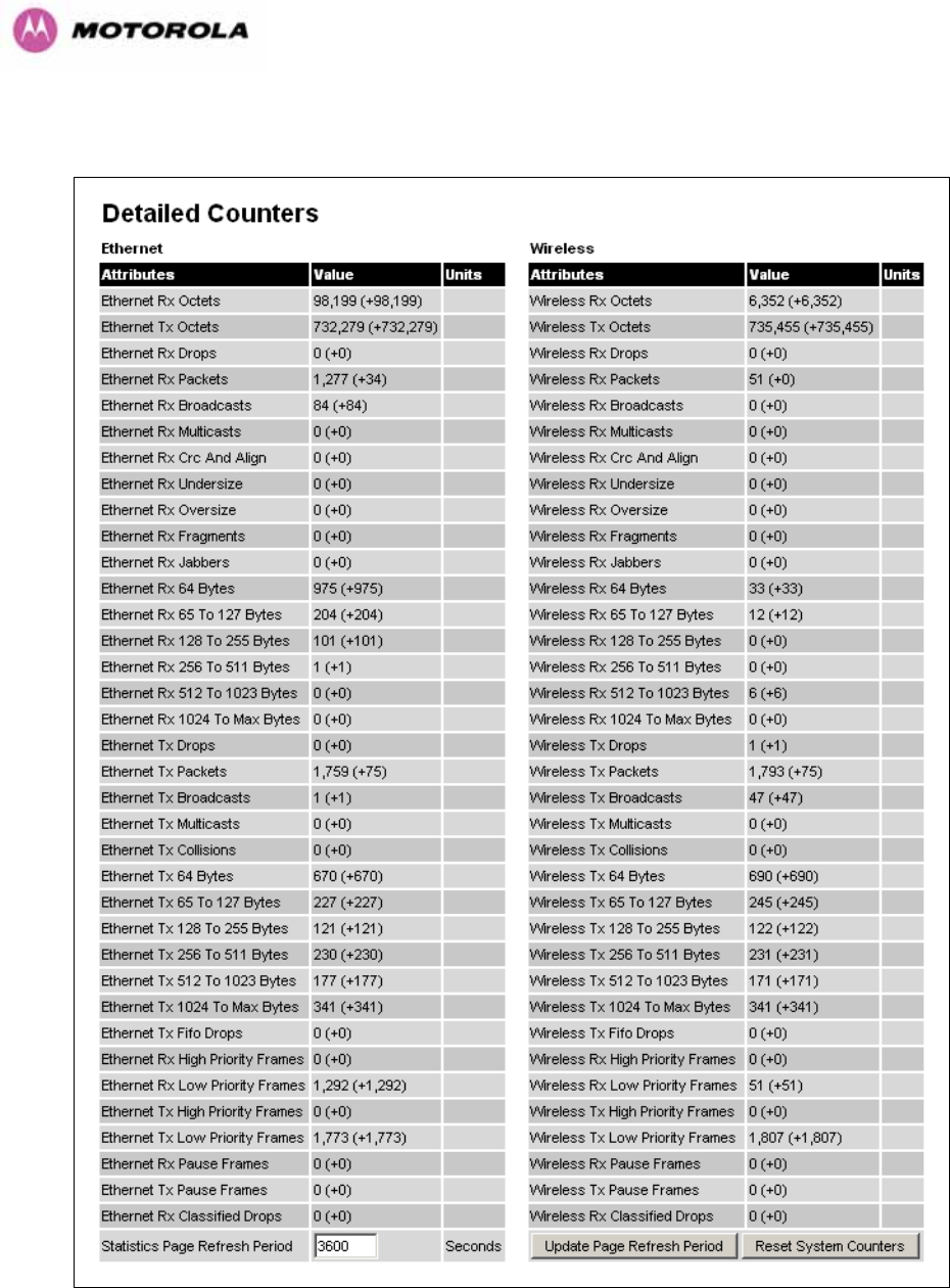
111
8.3.3 Detailed Counters Page
Figure 53 - Detailed Counters Page

112
The detailed counters page is subdivided into two columns. Column one presents the detailed
statistics for the bridge’s Ethernet interface. Column two relates to the wireless interface.
The Counters have the following definitions:
Tx & Rx Octets: Total number of octets (bytes) transmitted or received over the interface.
Rx Drops: Total number of frames dropped due to the lack of sufficient capacity in the
receive buffer.
Rx Packets: Total number of packets received by the interface. This includes both good and
bad packets.
Rx Broadcasts: Total number of good broadcast packets.
Rx Multicasts: Total number of good multicast packets.
Rx CRC and Align: Total number of packets with CRC or frame alignment errors.
Rx Undersize: Total number of packets received that are less than 64 bytes and have a valid
CRC.
Rx Oversize: Total number of packets received that are greater than the maximum number
of bytes with a valid CRC.
Rx Fragments: Total number of packets that are less than 64 bytes with an invalid CRC
(these packet types are also known as runts).
Rx Jabbers: Total number of packets received that are greater than the maximum number of
bytes with an invalid CRC.
Rx 64 Bytes: Total number 64 byte frames received
Rx 65 to 127 Bytes: Total number of frames received in the size range 65 to 127 bytes.
Rx 128 to 255 Bytes: Total number of frames received in the size range 128 to 255 bytes.
Rx 256 to 511 Bytes: Total number of frames received in the size range 256 to 511 bytes.
Rx 512 to 1023 Bytes: Total number of frames received in the size range 512 to 1023 bytes.
Rx 1024 to Max: Total number of frames received in the size range 1024 to Maximum bytes.
Tx Drops: Total number of frames dropped due excessive collisions, late collision and frame
ageing.
Tx Packets: Total number of packets received by the interface. This includes both good and
bad packets.
Tx Broadcasts: Total number of good broadcast packets.

113
Tx Multicasts: Total number of good multicast packets.
Tx Collisions: Total number frames experiencing collisions.
Tx 64 Bytes: Total number 64 byte frames transmitted
Tx 65 to 127 Bytes: Total number frames transmitted in the size range 65 to 127 bytes.
Tx 128 to 255 Bytes: Total number frames transmitted in the size range 128 to 255 bytes.
Tx 256 to 511 Bytes: Total number frames transmitted in the size range 256 to 511 bytes.
Tx 512 to 1023 Bytes: Total number frames transmitted in the size range 512 to 1023 bytes.
Tx 1024 to Max: Total number frames transmitted in the size range 1024 to Maximum bytes.
Tx FIFO Drops: Total number frames dropped due to lack of capacity in the transmit buffer,
for example when the 600 Series bridge is connected to the local Ethernet at a connection
speed of less than 1 Gbps.
Rx & Tx High Priority: Total number of received or transmitted frames marked as high
priority.
Rx & Tx Low Priority: Total number of received or transmitted frames marked as low priority.
Rx & Tx Pause Frames: Total number of received or transmitted pause frames.
Rx Classifier Drops: Total number of received frames dropped due to the application of
classifier rules.
Statistics Page Refresh Period: The statistics page refreshes automatically according to the
setting entered here (in seconds).
8.3.4 Install Pages
These pages are used during system installation. There follows a description of the install
pages along with their use during the installation configuration process. The actual installation
process is described in Section 1093H7.7.11.
All wireless links are shipped as paired units. They are pre-configured at the factory so that
they can be installed without the user supplying any configuration. Each wireless link is
shipped with a quick start guide. Attached to the quick start guide is a summary of the pre-
configured configuration data. 1094HTable 14 shows a sample link configuration. The values
highlighted have been committed to the wireless unit’s non-volatile storage.

114
Example PTP 600 Series Configuration Data
For your convenience these two units have been pre-configured as a link
Units:
ODU serial number ODU serial number
016780000FFF 016780000FC7
Ethernet MAC address Ethernet MAC address
00:04:56:80:0F:FF 00:04:56:80:0F:C7
Configured as:
Master Slave
Target MAC address Target MAC address
00:04:56:80:0F:C7 00:04:56:80:0F:FF
License Key License Key
A471-FE88-428D-E1F3 534F-4F54-D1B0-E2DA
IP Address IP Address
169.254.1.2 169.254.1.1
Table 14 – 600 Series Bridge Factory Configuration Values
The factory default configuration is limited in range to 40 Km (25 miles). If you wish to install a
wireless link with a range of > 40 Km (> 25 miles) and < 200 Km (< 124 miles) or < 5 Km (< 3
miles) you must follow the ‘1095HManually Configuring The Wireless Units’ in Section 1096H8.3.4.1.
The factory default configuration is set to Region 1. Region 1 allows the 600 Series bridge a
maximum transmit power of 25 dBm. If the local regulatory regime limits the maximum
transmit power (EIRP) to less than 25 dBm you should obtain a new license key containing
the correct region code from your local distributor or direct from Motorola. Alternatively in the
short term, you should reduce the maximum transmit power by following the procedures in
‘1097HManually Configuring The Wireless Units’ in Section 1098H8.3.4.1.
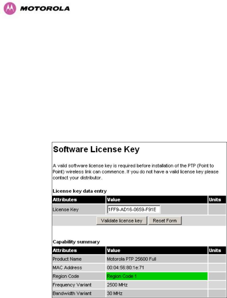
115
8.3.4.1 Manually Configuring The Wireless Units
If the installer / system administrator wishes, they may modify the default installation
configuration. If only the IP addresses (network configuration) are incorrect it is recommended
that the values are changed via the configuration menu (Section 1099H6.3.1.2). If any other
parameters require modification then it is recommended that the system administrator use the
Installation Wizard.
A detailed description of the Installation Wizard follows:
The 600 Series bridge operational software requires a license key to enable the wireless
bridging capability and programs region code specific parameters in to the unit.
Figure 54 - License Key Data Entry
A license key is programmed into each unit during production and can be found written on the
Configuration Data Summary Label which is attached to the Quick Install Guide. If
subsequently the license key has been mislaid, replacement keys can be applied for online or
via your distributor.
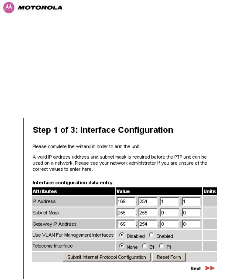
116
If a valid license key is not detected in the unit’s non-volatile memory then the user is
prompted to enter a valid key. It should be noted that 600 Series bridge units are shipped as
link pairs and, as such, valid license keys are entered during the production process. To enter
a license key simply type or paste the license key into the data entry box (1100HFigure 541101H) and click
the ‘validate license key’ button.
8.3.4.2 Internet Protocol Configuration
Step 1 of the installation wizard requires the installer to enter the Internet Protocol (IP)
configuration.
Figure 55 - Installation Wizard Internet Protocol Configuration
IP Address: Internet protocol (IP) address. This address is used by the family of Internet
protocols to uniquely identify this unit on a network.
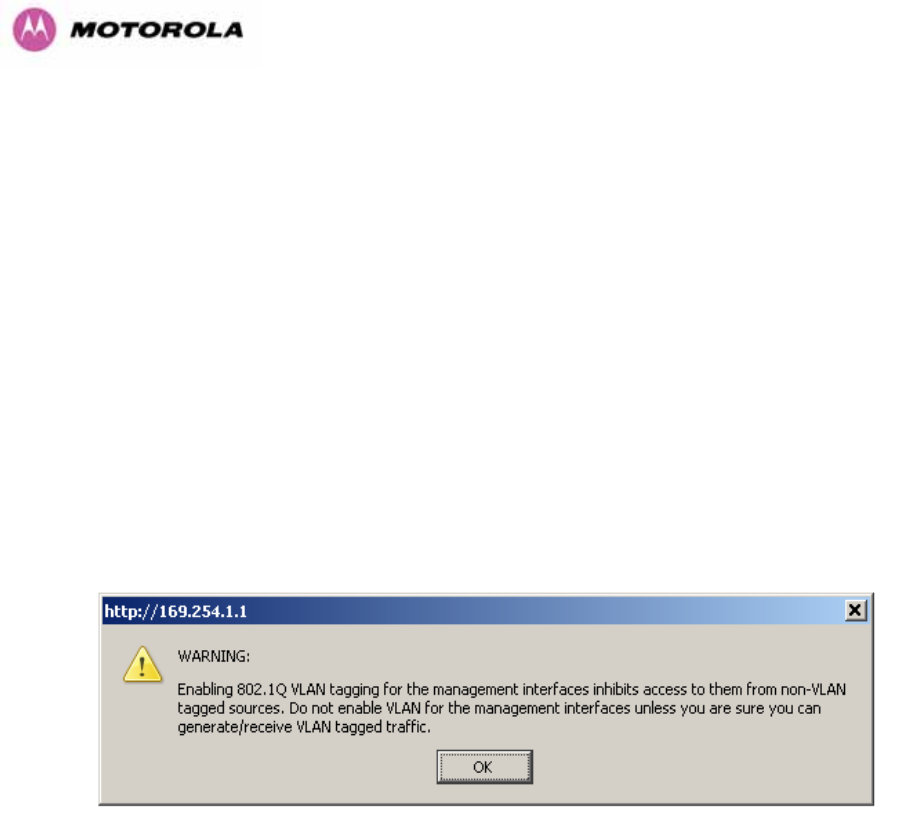
117
Subnet Mask: A subnet allows the flow of network traffic between hosts to be segregated
based on a network configuration. By organizing hosts into logical groups, subnetting can
improve network security and performance.
Gateway IP Address: The IP address of a computer / router on the current network that acts
as a gateway. A gateway acts as an entrance / exit to packets from / to other networks.
Use VLAN Management Interface: Controls whether the management interfaces
(HTTP/SNMP/SMTP/SNTP) use a VLAN. Selecting this option presents the user with extra
fields in which to enter the Management VLAN ID, Priority and whether to validate the VLAN
ID. If the user modifies this control, a warning dialog is displayed see 1102HFigure 56.
Telecoms Interface This allows the activation of the 600 Series bridge telecoms interface. If
the selection options are disabled, T1 or E1 note mixed T1/E1 configurations are not
permitted.
Figure 56 - VLAN Warning
Once complete, click the ‘Submit Internet Protocol Configuration’ button or the ‘Next’ link.
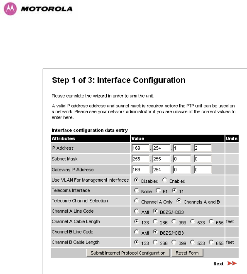
118
8.3.4.3 Telecoms Interface
If the telecoms interface is configured to either T1 or E1 then the web page will reconfigure
itself with the following additional configuration options.
Figure 57 - Telecoms Configuration Interface
Telecoms Channel Selection: This controls the selection of the telecoms interface standard
supported options or T1 and E1.
Channel A Line Code: The line code setting of the telecoms interface. This must match the
setting of the device connected to this interface.
Channel B Line Code: The line code setting of the telecoms interface. This must match the
setting of the device connected to this interface.
Cable Length: This field is applicable to the T1 operating mode only. It configures the T1
transceiver to output a signal suitable for driving a cable of the specified length. This should
be set to reflect the length of cable between the wireless unit and the connected equipment.
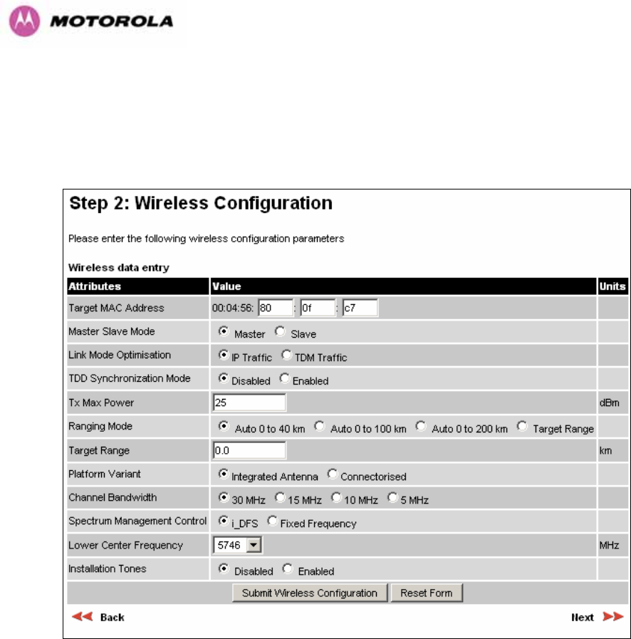
119
8.3.4.4 Wireless Configuration
Step 2 of the installation wizard requires the installer to enter the wireless configuration
parameters.
Figure 58 – 5.8 GHz and 5.4 GHz Variants - Installation Wizard Wireless Configuration
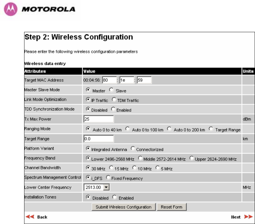
120
Figure 59 - 2.5 GHz Variant - Installation Wizard Wireless Configuration
Target MAC Address: It is the MAC Address of the peer unit that will be at the other end of
the wireless link. This is used by the system to ensure the unit establishes a wireless link to
the correct peer.
The MAC Address can be found embedded within the serial number of the unit. The last six
characters of the serial number are the last three bytes of the unit’s MAC address.
(Note: A PTP 600 Series system is shipped as a pair of units with pre-loaded correct MAC
addresses. MAC addresses will only need to be entered if an existing unit has to be replaced
in the field or the units configuration has been erased).
Master Slave Mode: At this point it is necessary to decide which end will designate a Master.
The Master unit is the controlling unit with respect to the point-to-point link and its
maintenance. The master transmits until the link is made, while the Slave listens for its peer
and only transmits when the peer has been identified.

121
Link Mode Optimization: Optimizes the link behavior according to the type of traffic that will
be bridged.
TDD Synchronization Mode: Enables the TDD Synchronization feature (see Section 1103H5.2 for
basic description and Section 1104H14 for installation and configuration details).
Tx Max Power: This attribute controls the maximum transmit power the unit is permitted to
use when installing and executing the wireless link. The maximum setting for a particular
region or country is controlled by the License Key.
Ranging Mode: During installation, the wireless units perform automatic ranging. The
ranging mode allows the installer to control the behavior of the system’s automatic ranging
algorithms. The default value is 0 to 40 km19F
20 (0 to 25 miles). If the installer is required to
install a link of greater than 40 km (25 miles) then the ranging mode attribute MUST be
configured to ‘0 to 100km’ (0 to 62 miles) or ‘0 to 200km’ (0 to 124 miles) mode depending on
the range of the link.
Target Range: Installers that know the range between the two wireless units to within ± 1 km
can use the target range mode. The main advantage of the target range mode is that it
reduces the time taken by the units to range. To use the target range mode the installer
MUST select Target Range as the ranging mode and enter the approximate range in km in
the Target range data entry field at both ends of the link.
Platform Variant: Chooses between an integrated unit or a connectorized unit that requires
an external antenna.
Frequency Band: This is for the 2.5 GHz product variant which operates in one of three
bands as described in Section 1105H5.5.
Channel Bandwidth: Users can choose a variable channel bandwidth for the available
spectrum. Values of 5 MHz, 10 MHz, 15 MHz and 30 MHz can be selected.
20 If preferred PTP 600 Series Bridge range functions can be configured to operate in miles, see the
Properties page in Section 8.3.15.

122
Spectrum Management Control: Is used to configure the PTP 600 Series Bridge’s
Spectrum Management features, see Section 1106H8.3.7 for more details. i-DFS is the abbreviation
for intelligent Dynamic Frequency Selection. This feature continually monitors the spectrum
looking for the channel with the lowest level of on channel and co-channel interference. Fixed
frequency mode allows the installer to fix transmit and receive frequencies on the units. The
frequencies may be configured symmetrically or asymmetrically.
Lower Center Frequency: The software for the PTP 600 Series Bridge allows a user to
optionally adjust the channel center frequencies. Changing the Lower Center Frequency
attribute causes all channel center frequencies to be offset. It effectively slides the
channelization up or down. See Sections 1107H5.5 and 1108H5.7 for more detail.
Warning: The lower center frequency attribute must be configured to the same value for both
the master and slave. Failure to do so will cause the wireless link to fail reestablishment. The
only way to recover from this situation is to modify the Lower Center Frequency attribute so
that they are identical on both the master and slave unit.
Fixed Transmit Frequency, Fixed Receive Frequency: The software for the PTP 600
Series Bridge allows a user to optionally fix the Transmit and the Receive frequencies for a
wireless link. The settings must be compatible at each end of the link. Once configured the
spectrum management software will not attempt to move the wireless link to a channel with
lower co or adjacent channel interference. Therefore this mode of operation is only
recommended for deployments where the installer has a good understanding the prevailing
interference environment. 1109HFigure 601110H shows a sample fixed frequency configuration for a 30
MHz channel bandwidth. In the example the lower center frequency is set to its default values
and the Fixed Transmit Frequency is set to 5742 MHz and the Fixed Receive Frequency is
set to 5742 MHz. Care must be taken when configuring the Fixed Transmit and Receive
Frequencies to ensure that both frequencies are on the same 10 MHz channel raster as the
Lower Center Frequency. For example both the Fixed Transmit and Receive Frequencies
must be a multiple of 10 MHz from the Lower Center Frequency (5752 = 5742 + 10 MHz) and
(5782 = 5742 + 10 MHz × 3). See Sections 1111H5.5 and 1112H5.7 for more detail.
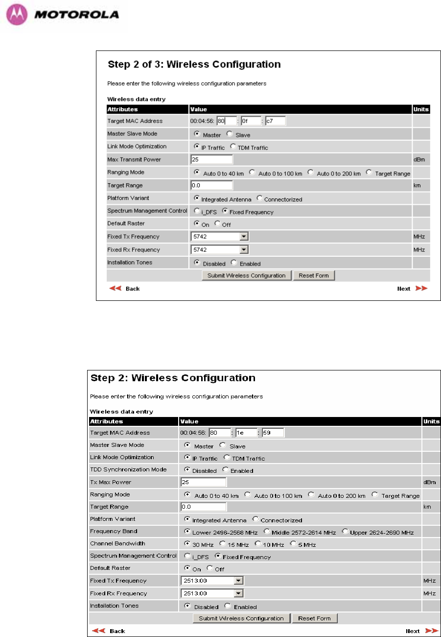
123
Figure 60 – 5.8 GHz and 5.4 GHz Variants - Fixed Frequency Operation
Figure 61 - 2.5 GHz Variant - Fixed Frequency Operation
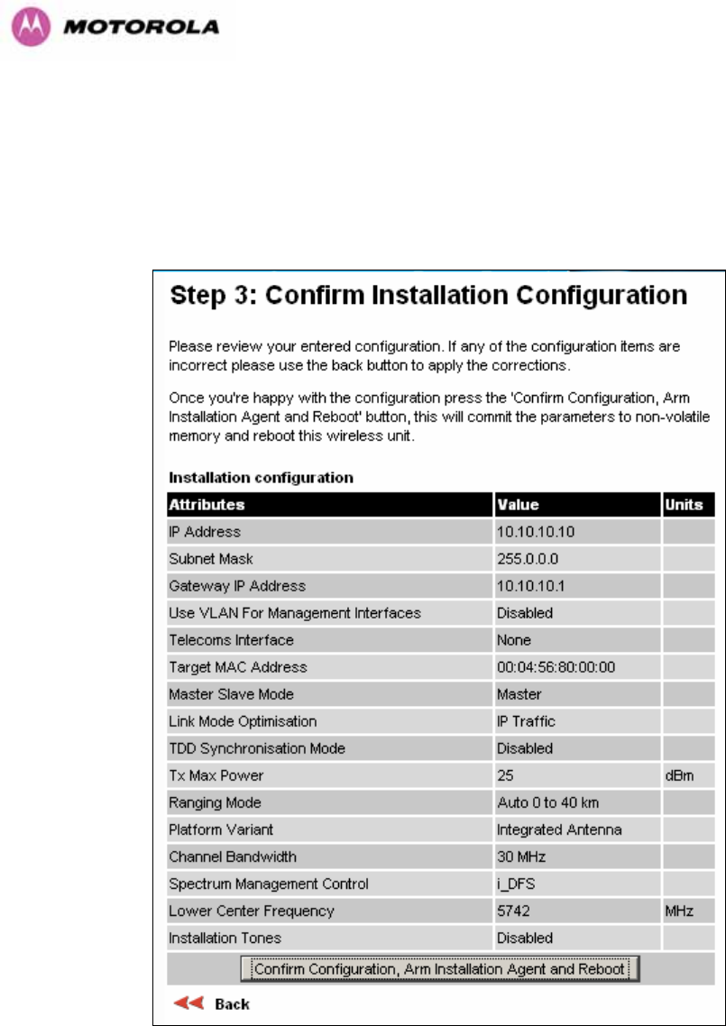
124
Installation Tones: Where the use of audio installation tones is not required this control
allows the installer to optionally disable the tone generator during the installation process.
Once the installer is satisfied with the wireless configuration options then the “Submit
Wireless Configuration” button or the “Next” link should be clicked.
Figure 62 – 5.8 GHz and 5.4 GHz Variants - Installation Wizard Confirm Configuration
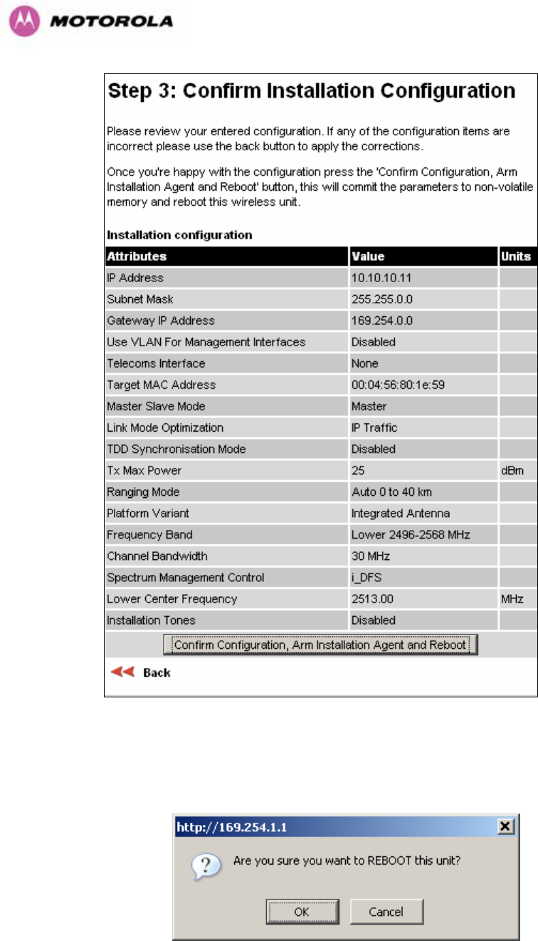
125
Figure 63 - 2.5 GHz Variant - Installation Wizard Confirm Configuration
If the settings are correct and appropriate, click the “Confirm Configuration, Arm Installation
and Reboot” button. The user will now be prompted to confirm the action (1113HFigure 641114H).
Figure 64 - Reboot Confirmation Pop Up
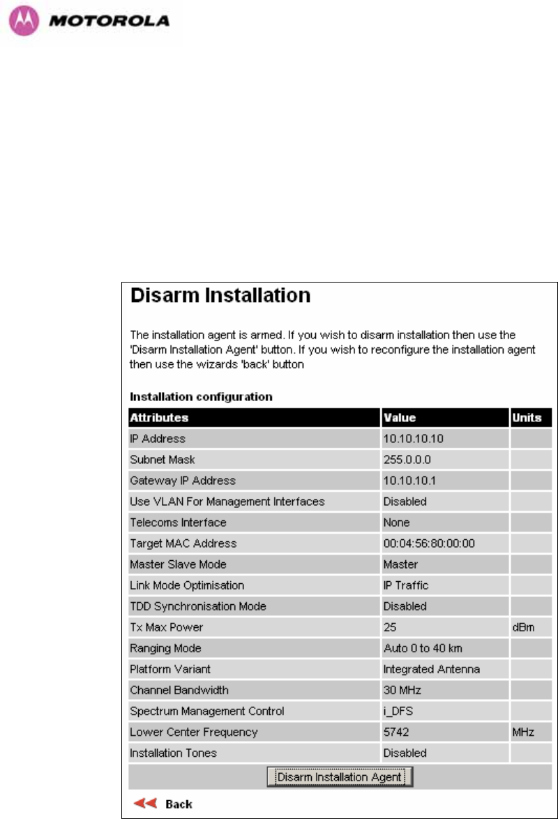
126
All the attributes are committed to non-volatile memory. Immediately following the write to
non-volatile memory the unit is reset.
Note: If you have changed the Ethernet parameters you must reconnect using the correct
network and address settings.
8.3.4.5 Disarm
Step 5 of the installation wizard is the disarm phase.
Figure 65 – 5.8 GHz and 5.4 GHz Variant - Disarm Installation
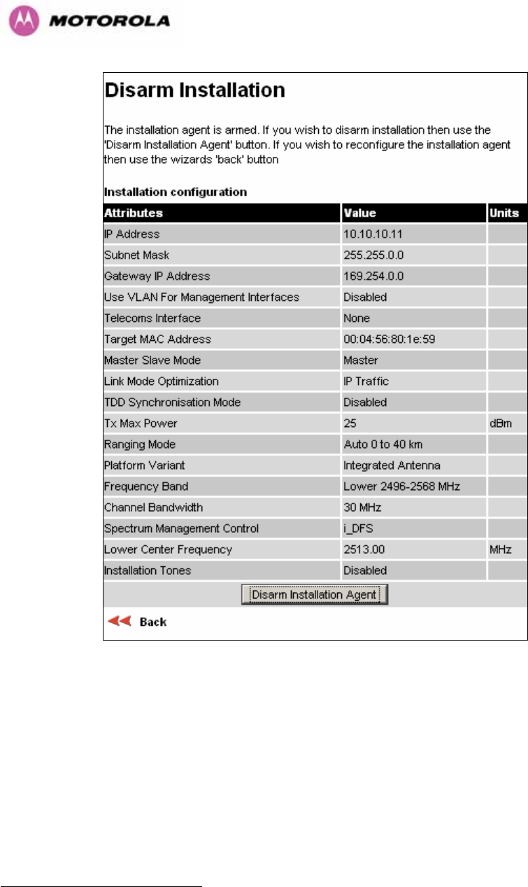
127
Figure 66 - 2.5 GHz Variant - Disarm Installation
Once Section 1115H8.3.4.4 is complete pressing the “Disarm Installation Agent” button completes
the installation process20F
21 and the audible installation tone will be switched off. If the installer
wishes to modify the installation configuration then the ‘Back’ link can be used to access the
installation wizard steps described above.
21 The installation process is completed when both ends of the link are ‘disarmed’.
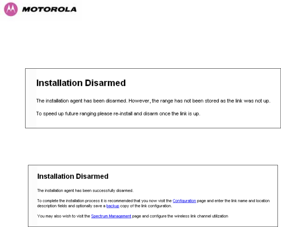
128
After disarming the wireless link the user is presented with one of two possible configuration
pages, see 1116HFigure 67 and 1117HFigure 68. The screen presents hyperlinks to the main
configuration and spectrum management pages.
Figure 67 - Optional Post Disarm Configuration 1
Figure 68 - Optional Post Disarm Configuration 2
After installation the system administrator may wish to modify the wireless units descriptive
configuration (link name and link location). In addition the system administrator may wish to
change the spectrum management configuration of the wireless unit, or look at the analysis of
the 5.8 GHz spectrum to see if the automatic channel selection is appropriate for the system
administrator’s network. It is also recommended that a backup copy of the wireless units
configuration is taken. Hyperlinks are provided on the post disarm page for ease of use.
8.3.5 Graphical Install
To aid the installation of wireless links two graphical installation aids have been introduced in
this 600 Series system version.
• A PDA installation screen
• A larger installation screen available from the main HTTP management interface.
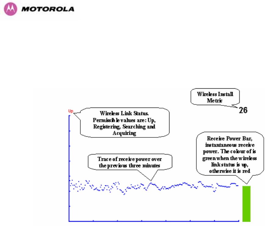
129
The design of the installation screen has been deliberately kept simple and uncluttered. An
example of the installation screen is shown in 1118HFigure 69. Both the PDA and the large format
installation screen have the same content and only differ in size. The PDA installation screen
is 232 by 220 pixels to be compatible with the typical size of a PDA screen.
Figure 69 – Graphical Installation Screen
The screen displays the receive power over the last three minutes. This will allow the installer
to slowly sweep the antenna during installation and monitor the variation in signal strength
with angular position. The screen automatically refreshes every three seconds.
The screen also displays the current state of the wireless link in two ways. First, the actual
state of the wireless link is written in the top left corner of the screen. The instantaneous
receive power bar also encodes the state of the wireless link using green to signify that the
wireless link is up and red for all other states.
For the more technically, aware the installation metric is simply the instantaneous receive
power in dBm + 100.
The PDA installation tool is accessed via a hidden URL http://<ip-address>/pda.cgi. It should
be noted that this link is only available after the user has logged in as system administrator.
The large screen version of the graphical user interface is available as a submenu option of
the installation wizard.
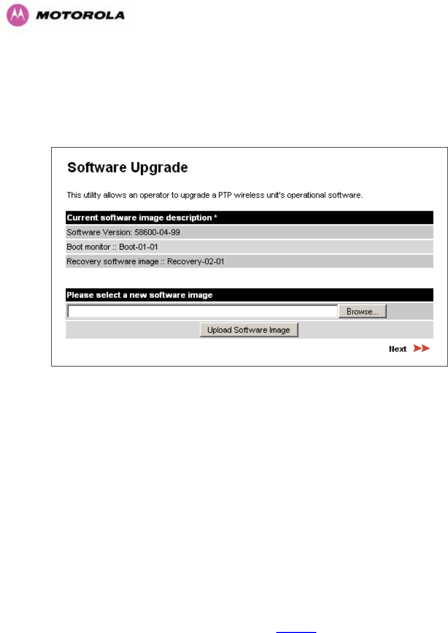
130
8.3.6 Software Upgrade
The 600 Series system has two software image banks; one is a fixed image which is stored in
protected non-volatile memory and cannot be modified by the user. The second bank is used
by the system administrator to upgrade the firmware when necessary. 1119HFigure 701120H shows the
main software upgrade web page.
Figure 70 - Software Upgrade
The ‘Fixed’ or ‘Recovery’ image is used by the System Administrator to:
o Reset Ethernet configuration to default settings
o Erase Configuration
o Upgrade software
For a full description of the Recovery image see Section 1121H9.
The software upgrade pages are used to update a unit’s operational software. The software
image to be uploaded should be downloaded to local storage from the Motorola web site. The
software image is delivered by Motorola as a compressed zip file. Once the zip file has been
downloaded, the user should extract the PTP 600 Series Software image, identifiable by its
‘.dld’ file extension.
The first step (1122HFigure 70) is to use the “Browse” button to locate the software image
previously downloaded to local storage from the 480HMotorola web site. Once the image is
located, the user should press the “Upload image to wireless unit” button to start the software
upgrade process.
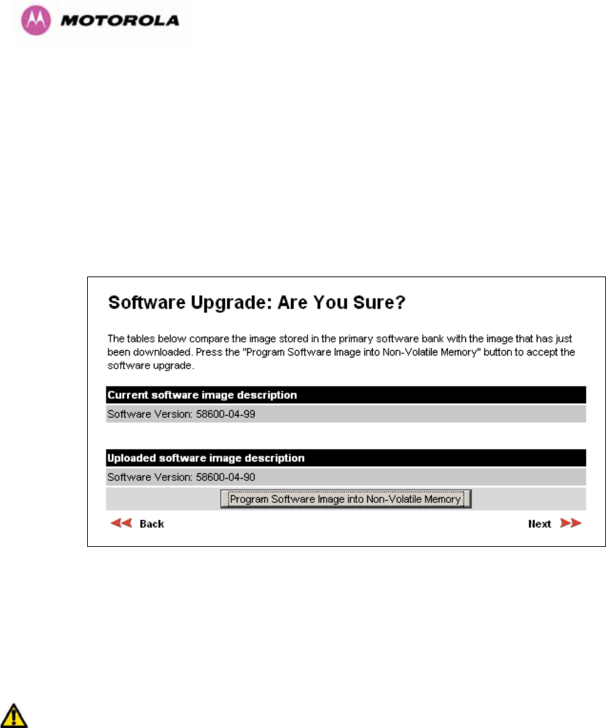
131
The software image will now be uploaded to the unit. This upload should only take a few
seconds. Once complete the image is verified and validated to ensure that no errors occurred
during transfer and that the image is valid to run on the current platform. If there are any
problems a warning screen will appear.
The unit being upgraded will now display information about the build it currently has stored in
the image bank and the one that’s just been uploaded. If the image is not the right one, the
user has the option to go back and reload a new image. (See 1123HFigure 71)
Figure 71 - Software Upgrade Image Check
The user should ensure that the correct image is shown before pressing the “Program
Software Image into Non-Volatile Memory” button. Once this button has been pressed the
image is stored into non-volatile memory, this process can take up to 60 seconds and must
not be interrupted.
If the upgrade process is interrupted during the erasure of the image bank, or during the
reprogramming of the image bank, the image bank will be left in a corrupt state. If this occurs
the software must be reloaded. All software images that are stored in non-volatile memory are
protected via the use of CRCs. If the software detects an invalid CRC the image bank is
marked as ‘corrupt’ and the 600 Series bridge boot code will boot the fixed software image. If
this occurs the user must attempt to reload the correct version of software.
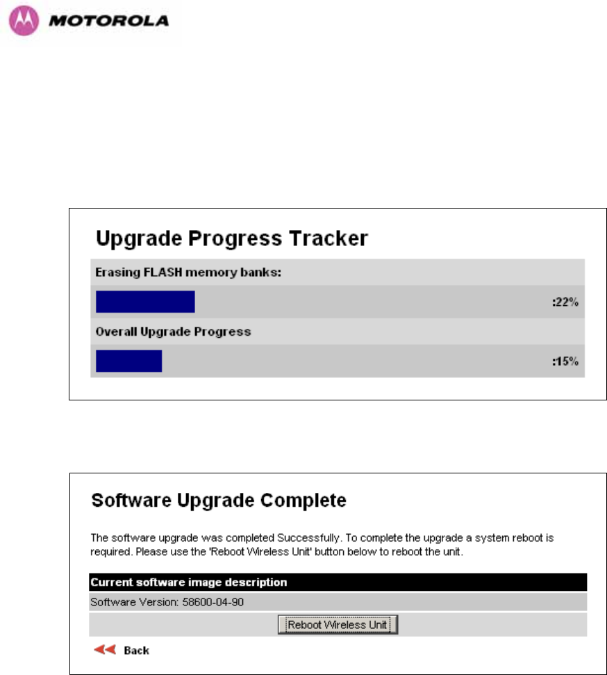
132
During the write process the progress of the upgrade is displayed on the progress tracking
page (1124HFigure 72). The upgrade process should not be interrupted. Interruption of this process
can result in a corrupt main software image, which will result in the recovery image been
booted at the next reset cycle.
Figure 72 - Software Download Progress Indicator
Figure 73 - Software Upgrade Complete
When the software image has been written to non-volatile memory 1125HFigure 73 will be displayed
showing the status of the software upload.

133
Reboot the unit by clicking the “Reboot Wireless Unit” button. You will be asked to confirm
this action as shown in 1126HFigure 74.
Figure 74 - Reboot Confirmation Pop Up

134
This will reboot the unit, taking up to 120 seconds. During this time you will not be able to
communicate with the unit.
If you cannot communicate with the unit after 120 seconds, this could indicate a problem with
the memory update process. Under these circumstances the user should enter “Recovery
Mode”, see Section 1127H9.
After the reboot the user should check that the required software image is loaded and
running.
NOTE: Please ensure that you are upgrading the correct units. Units cannot be downgraded
and license keys cannot be swoped once upgraded.
8.3.7 Spectrum Management
Spectrum Management Selection is the PTP 600 Series Bridge feature that monitors the
available wireless spectrum and directs both ends of the wireless link to operate on a channel
with a minimum level of co-channel and adjacent channel interference.
8.3.7.1 Wireless Channels
The PTP 600 Series Bridge operates using a set of predefined overlapping channels. There
are a different number of channels, depending on the raster mode selected. Each channel
occupies 30 MHz, 15 MHz, 10 MHz or 5 MHz of wireless spectrum and is offset in center
frequency from its neighboring channel by 10 MHz or 6 MHz. It is important to note that
adjacent channels on the Spectrum management display have a 10 MHz or 6 MHz overlap to
the adjacent channel.
The default channelization can be modified by varying the lower center frequency attribute in
the installation wizard - see Section 1128H8.3.4.4. See Section 1129H5.5 and 1130H5.7 for more detail.

135
8.3.7.2 Spectrum Management Measurements
The 600 Series Bridge performs two mean signal measurements per TDD cycle, per channel.
This mean measurement represents the mean received signal power for the 40 μS
measurement period.
The Spectrum Management algorithm collects measurements equally from all channels. This
process is called the Channel Availability Check (hereafter referred to by the acronym CAC).
The CAC uses a round-robin channel selection process to collect an equal amount of
measurements from each channel. It is important to note that the CAC measurement process
is not altered by the channel barring process. Measurements are still collected for all
channels irrespective of the number of barred channels.
8.3.7.3 Measurement Analysis
Spectrum Management uses statistical analysis to process the received peak and mean
measurement. The statistical analysis is based on a fixed, one minute, measurement
quantization period. Spectrum Management collects data for the specified quantization period
and only at the end of the period is the statistical analysis performed.
The analysis produces three key metrics for each channel:
o Peak of Means
o 99.9% Percentile of the Means
o Mean of Means
Peak of Means is the largest mean interference measurement encountered during the
quantization period. The peak of means is similar to the peak of peaks and is useful for
detecting slightly longer duration spikes in the interference environment.
99.9% Percentile of the Means is the value of mean interference measurement which 99.9%
of all mean measurements fall below, during the quantization period. The 99.9% percentile
metric is useful for detecting short duration repetitive interference that by its very nature has a
minimal effect of the mean of means.

136
Mean of Means is the arithmetic mean21F
22 of the measured means during a quantization
period. The mean of means is a coarse measure of signal interference and gives an
indication of the average interference level measured during the quantization period. The
metric is not very good at predicting intermittent interference and is included to show the
spread between the mean of means, the 99.9% percentile and the peak of means.
Important Note: Spectrum Management uses the 99.9% percentile as the prime interference
measurement. All subsequent references to interference level refer to this percentile
measurement.
The display of statistical measurement on the spectrum management page always shows a
statistical summary of all channel measurement. The statistical summary is controlled by the
Statistics Window attribute. This attribute defaults to a value of twenty minutes, which means
that the mean and percentile values displayed for each channel are calculated over the 20
minute period. All channel decisions are made using the values computed over the statistics
window period.
8.3.7.4 The Spectrum Management Master / Slave Relationship
By default Spectrum Management operates in a master / slave relationship. The master is
assumed to be the link master configured during installation. All Spectrum Management
configuration changes MUST be performed from the master. To enforce this, the Spectrum
Management web page has a different appearance depending if you are viewing the data
from the master or slave.
All configuration changes are applied at the master only. These changes are then messaged
from the master to the slave. Any Spectrum Management configuration messages received at
the slave are stored in non-volatile memory. This enables both master and slave to keep
identical copies of Spectrum Management configuration data in their non-volatile memories. It
is therefore possible to swap master and slave roles on an active Point-to-Point link without
modifying Spectrum Management configuration.
22 The arithmetic mean is the true power mean and not the mean of the values expressed in dBm.
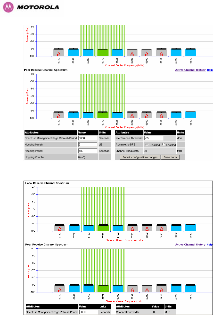
137
Figure 75 - Spectrum Management as seen from the Master
Figure 76 - Spectrum Management as seen from the Slave

138
1131HFigure 75 shows an example Spectrum Management webpage as seen from the master.
1132HFigure 76 shows an example Spectrum Management webpage as seen from the slave. It
should be noted that the key configuration attributes are not available on the slave web page.
8.3.7.5 Spectrum Management Configuration
The following section describes the user modifiable configuration accessible from the
Spectrum Management webpage. It is recommended that the default values are maintained.
If the user believes that the performance of the Spectrum Management algorithm requires
some modifications this should only be done after consulting your Motorola Point-to-Point
distributor or one of the system field support engineers.
Page Refresh Period: The page refreshes automatically according to the setting entered
here (in seconds).
Hopping Margin: Spectrum Management uses this margin when making a channel hop
decision. The target channel has to have an interference level 3 dB (default) better than the
current active channel.
Hopping Period (not configurable): The Spectrum Management algorithm evaluates the
metrics every ‘Hopping Period’ seconds (180 seconds by default) looking for a channel with
lower levels of interference. If a better channel is located, Spectrum Management performs
an automated channel hop. If SNMP or SMTP alerts are enabled an SNMP TRAP or an email
alert is sent warning the system administrator of the channel change.
Hopping Counter: is used to record the number of channel hops. The number in the “(+)”
brackets indicates the number of channel changes since the last screen refresh.
Interference Threshold: Spectrum Management uses the interference threshold to perform
instantaneous channel hops. If the measured interference on a channel exceeds the specified
threshold, then iDFS will instruct the wireless to immediately move to a better channel. If a
better channel cannot be found the 600 Series Bridge will continue to use the current active
channel. (Default –85 dBm)
Asymmetric DFS: The default configuration of symmetric operation constrains the link to
operate symmetrically, using the same transmit and receive channels. When in symmetric
mode the slave unit will always follow the master. If the master moves to a new channel the
slave will hop to the same channel. When the Point-to-Point link is configured as an
asymmetric link both the master and slave are free to select the best channel from their own
set of local interference metrics.
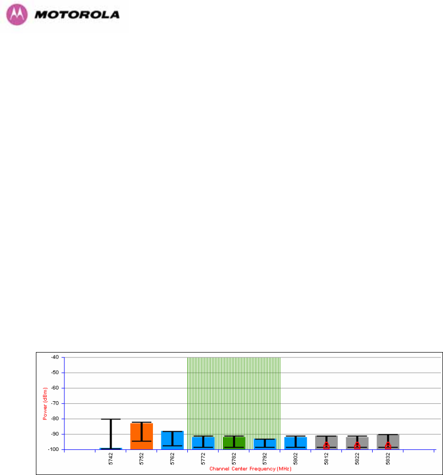
139
Channel Bandwidth (not configurable): shows the value of the variable channel bandwidth
selected.
8.3.7.6 Barring Channels
Channels can only be barred / unbarred by the system administrator from the master
Spectrum Management web page. The barring / unbarring operations are disabled on the
slave web page. If an attempt to bar / unbar a channel is made at the slave, a warning dialog
is generated.
Barring/Unbarring of channels is performed by clicking the appropriate channel on the local or
peer channel spectrum plots on the master web page. Each bar / unbar attempt will be
proceeded by a confirmation dialog. It should be noted that the channel bar will take effect
immediately and is not related to the measurement quantization period.
8.3.7.7 Local and Peer Channel Spectrum Graphics
Spectrum Management presents its computed statistical measurements in a graphical display
on both the master and slave Spectrum Management web page.
Figure 77 - Example Spectrum Management Graphic
The X-axis shows a stylized view of the 9 or 10 selectable wireless channels. It is important
to note that adjacent channels on the display have a 10 MHz overlap. The display separates
the display of channels to help the clarity of the resultant display. The axis is labeled using the
channel center frequencies in MHz.
The Y-axis shows the interference power levels from –100 to –40 dBm.

140
The active channel (channel 5 in 1133HFigure 77) is always marked using hatched green and white
lines. The width of the hatching is directly proportional the 30 MHz spectral occupancy of the
channel.
The individual channel metrics are displayed using a colored bar and an ‘I’ bar.
The colored bar represents the following channel state:
Green Active The channel is currently in use, hosting the Point-to-Point
wireless link
Orange Interference The channel has interference above the interference threshold
Blue Available
The channel has an interference level below the interference
threshold and is considered by the Spectrum Management
algorithm suitable for hosting the Point-to-Point link
Grey Barred
The system administrator has barred this channel from use.
For improved visibility, an additional red ‘lock’ symbol is used
to indicate that a channel is barred.
Table 15 - Spectrum Management change state key
The top of the colored bar represents the 99.9% percentile metric for specific channel.
The ‘I’ Bar is used to display the mean of means and peak of means metrics. The lower
horizontal bar represents the mean of means and the upper horizontal bar represents the
peak of means. The vertical bar is used as a visual cue to highlight the statistical spread
between the peak and the mean of the statistical distribution.
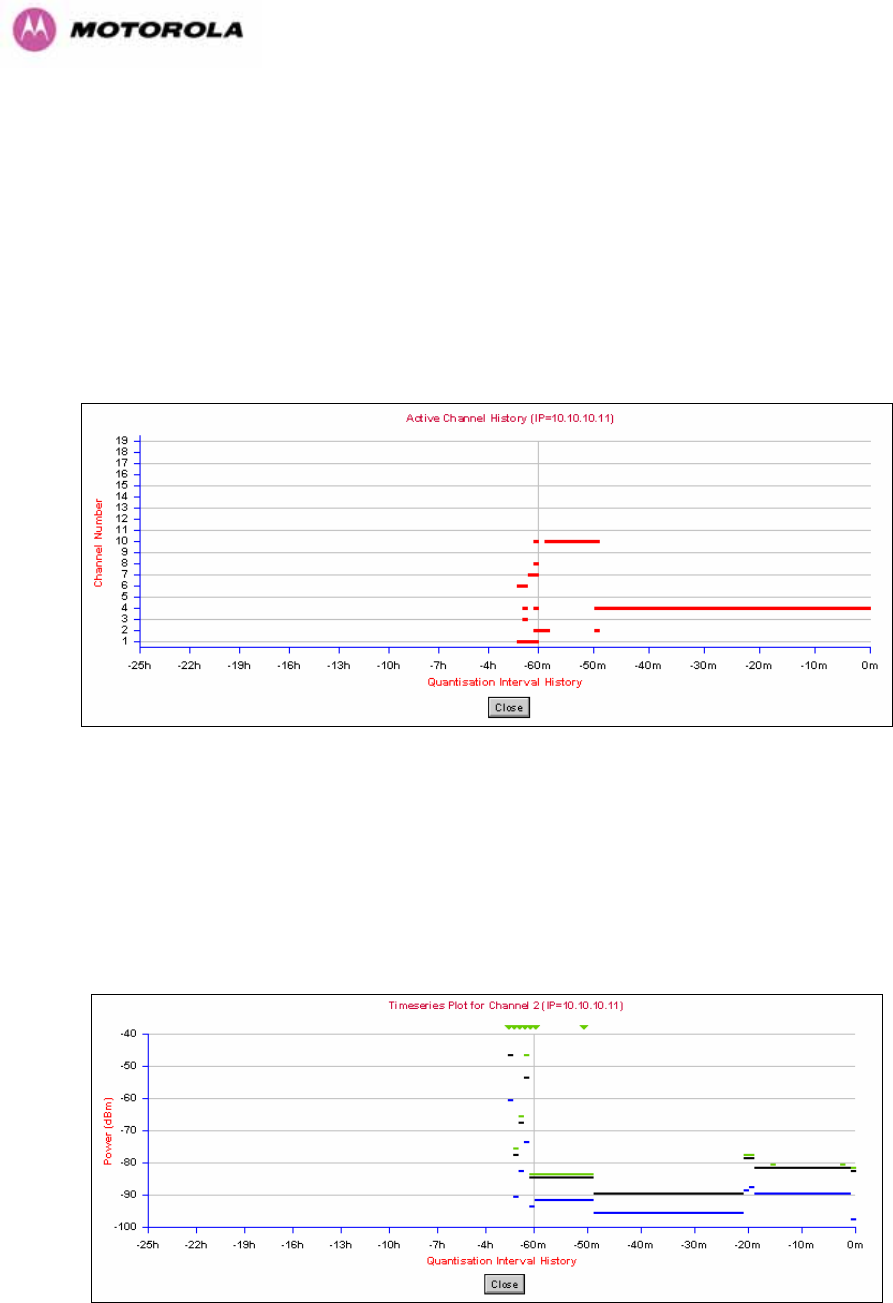
141
8.3.7.8 Active Channel History
The active channel history is a time series display of the channels used by the PTP 600
Series Bridge over the last 25 hours. The active channel history is activated from the main
Spectrum Management page using the ‘Active Channel History’ hyperlink. An example of the
active channel history display is shown in 1134HFigure 78. Where there are parallel entries on the
display this signifies that the wireless link occupied this channel during the measurement
period. The measurement periods are one minute (from zero to sixty minutes) and twenty
minutes from (60 minutes to twenty five hours).
Figure 78 - Active Channel History Screen
8.3.7.9 Viewing Historic Spectrum Management Metrics
Spectrum Management allows the system administrator to view the results of previous
measurement quantization periods. Holding down the shift key and clicking the appropriate
channel on the local channel spectrum plots activates this feature. This feature is available on
both the master and slave web page.
Figure 79 - Spectrum Management Time Series Plot

142
1135HFigure 79 shows an example time series plot. A time series plot displays the previous 132
measurement quantization periods. If the PTP 600 Series Bridge has not been running for
132 quantization periods then only the number of measurement quantization periods that are
available are displayed.
GREEN Peak of Means interference measurement
BLACK 99.9% percentile of means interference measurement
BLUE Mean of Means interference measurement
Table 16 - Spectrum Management Time Series Key
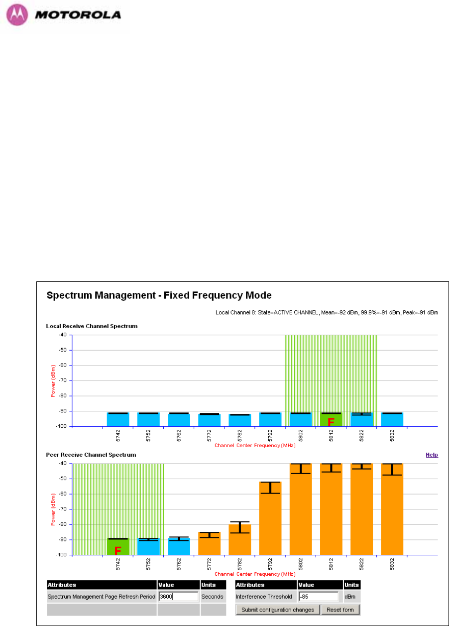
143
8.3.8 Spectrum Management (Fixed Frequency and WIMAX)
The PTP 600 Series Bridge software allows a user to optionally fix transmit and receive
frequencies for a wireless link. Once configured, the spectrum management software will not
attempt to move the wireless link to a channel with lower co and adjacent channel
interference. Therefore this mode of operation is only recommended for deployments where
the installer has a good understanding the prevailing interference environment. (See Section
1136H8.3.4.4). Care must also be taken to ensure that the frequency allocations at each end of the
link are compatible. To help the user when identifying the mode of operation Spectrum
Management uses two visual cues. See 1137HFigure 80. The main page title identifies the mode of
operation using the “Fixed Frequency Mode” postfix and the selected channels are identified
by a red capital ‘F’.
Figure 80 - Spectrum Management Fixed Frequency Screen
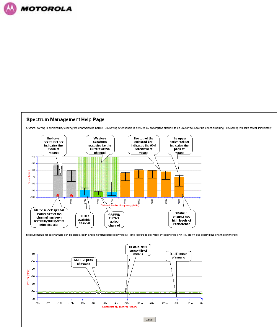
144
Channel barring is disabled in fixed frequency mode; it is not required as dynamic channel
hopping is prohibited in this mode.
The only controls available to the master are the Statistics Window and Interference
Threshold attributes. They will have no effect on the operation of the wireless link and will
only effect the generation of the channel spectrum graphics.
The active channel history menu is removed in this mode of operation as channel hopping is
prohibited.
Figure 81 - Spectrum Management Help Page (Fixed Frequency)
8.3.9 Spectrum Management Control - With Operational Restrictions
When operating with Radar Avoidance enabled the following variances in operation apply:
• The words “Radar Avoidance” are appended to the “Spectrum Management” title at the
top of the screen. See 1138HFigure 82 and 1139HFigure 83.
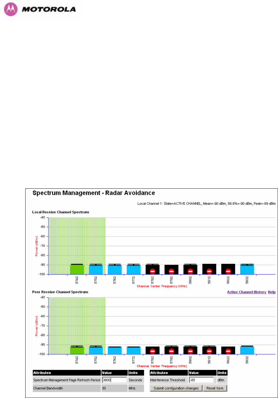
145
• The only controls available to the master are the Interference Threshold attribute. This
has no effect on the operation of the wireless link and will only affect the generation of the
channel spectrum graphics. See 1140HFigure 82.
• Extra color coding of the interference histogram is provided. See 1141HTable 17.
When operating with RTTT Avoidance enabled or other regulatory restrictions on channel
usage the following variances apply:
• All channels marked with a ‘no entry’ symbol with their associated statistics colored black
are the prohibited channels. See 1142HFigure 82 and 1143HFigure 83. These channels are never
used to host the wireless link, but CAC measurements are still taken so that adjacent
channel biases can be calculated correctly and so the user can see if other equipment is
in use.
Figure 82 - Spectrum Management Master Screen With Operational Restrictions
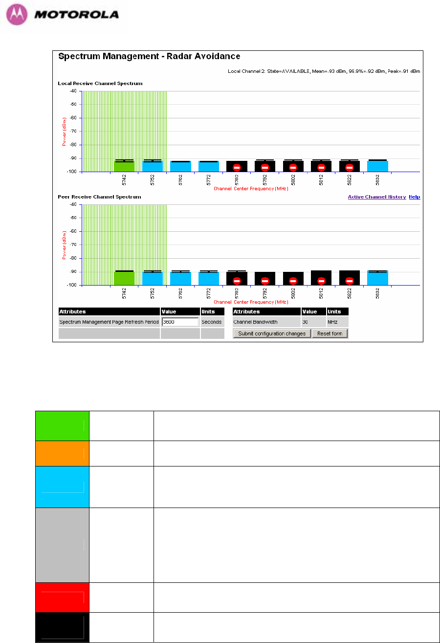
146
Figure 83 - Spectrum Management Slave Screen With Operational Restrictions
The colored bar represents the following channel state:
Green Active The channel is currently in use hosting the Point-to-Point
wireless link
Orange Interference The channel has interference above the interference threshold
Blue Available
The channel has an interference level below the interference
threshold and is considered by the Spectrum Management
algorithm suitable for hosting the Point-to-Point link
Grey Barred
The system administrator has barred this channel from use.
Because the low signal levels encountered when a unit is
powered up in a laboratory environment prior to installation
(which makes the grey of the channel bar difficult to see). An
additional red ‘lock’ symbol is used to indicate that a channel is
barred.
Red Radar
Detected
Impulsive Radar Interference has been detected on this
channel.
Region
Bar Region Bar This channel has been barred from use by the local region
regulator
Table 17 - Spectrum Management Change State Key With Operational Restrictions
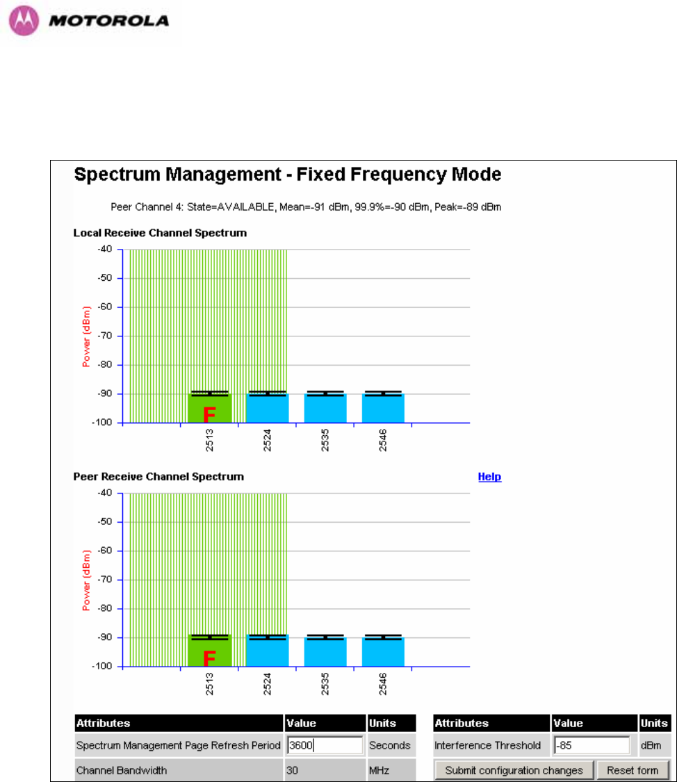
147
8.3.10 Spectrum Management – Example of 2.5 GHz Product variant
As described in Section 1144H52, the 2.5 GHz product variant can operate in three frequency
bands. 1145HFigure 84 shows an example of a Lower Band with a 30 MHz channel bandwidth.
Figure 84 - 2.5 GHz Example of Spectrum Management Page
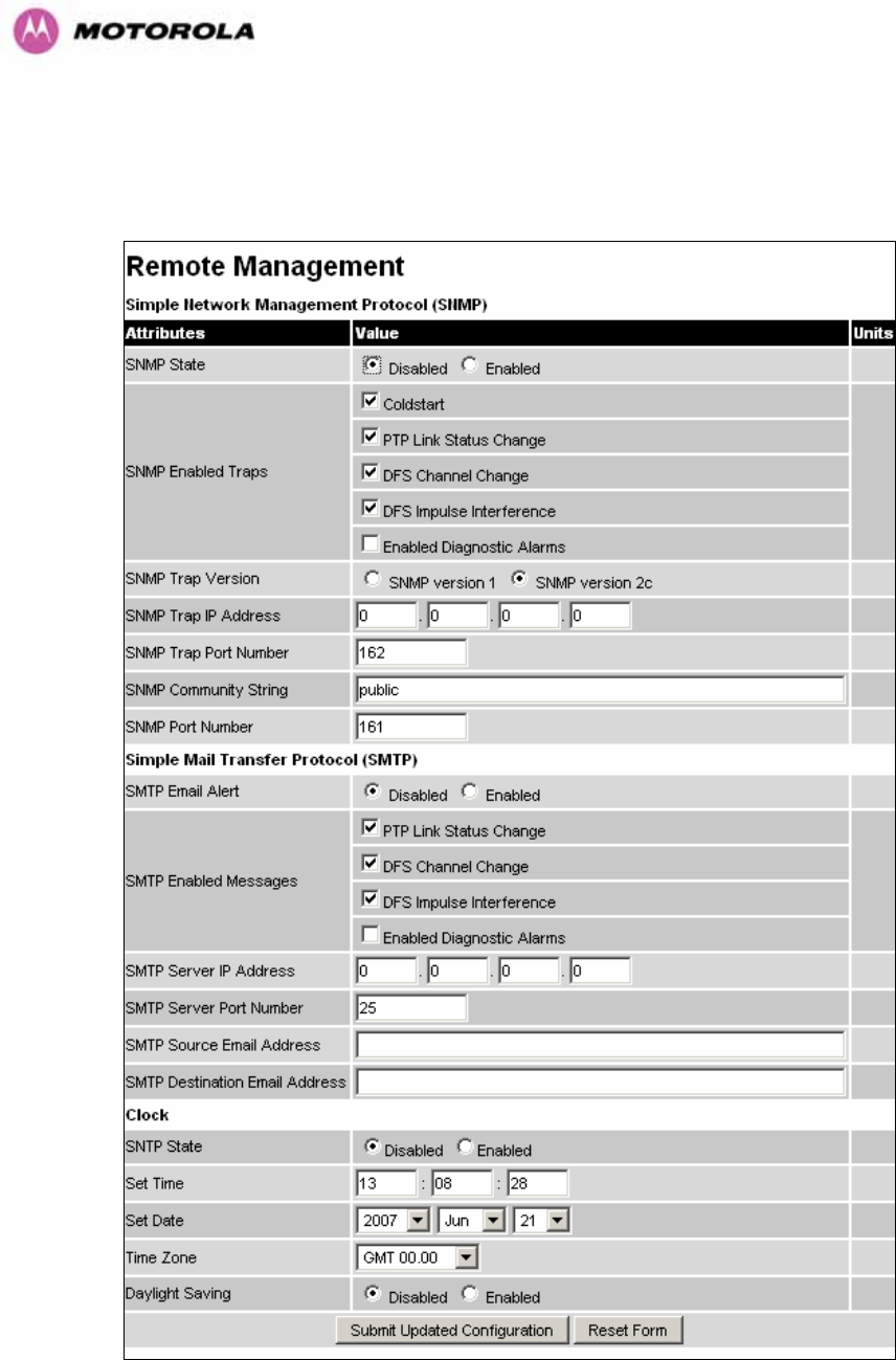
148
8.3.11 Remote Management Page
The Remote Management page (1146HFigure 85) allows the system administrator to configure the
remote management of the PTP 600 Series Bridge.
Figure 85 - Remote Management

149
8.3.11.1 SNMP (Simple Network Management Protocol)
The industry standard remote management technique is SNMP (Simple Network
Management Protocol). The PTP 600 Series Bridge supports version 1 and version 2c of the
SNMP protocol.
8.3.11.2 Supported Management Information Bases (MIBS)
The PTP 600 Series Bridge SNMP stack currently supports three distinct MIBs:
• MIB-II, RFC-1213, The PTP 600 Series Bridge supports the ‘System Group’ and
‘Interfaces Group’.
• Bridge MIB, RFC-1493, The PTP 600 Series Bridge supports the ‘dot1dBase Group’ and
the ‘dot1dBasePortTable Group’.
• PTP 600 Series Bridge proprietary MIB
• RFC-2233 (High capacity counter) MIB
• WiMAX MIB
SNMP TRAPs supported:
• Cold Start
• Link Up
• Link Down
• DFS Channel Change
• DFS Impulsive Interference
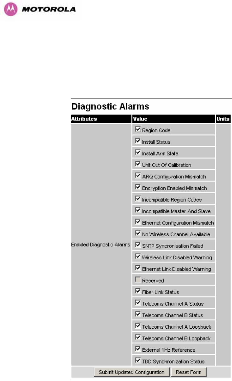
150
8.3.11.3 Diagnostics Alarms
A number of diagnostics alarms have been added to allow SNMP agents to receive traps and
emails if required. Checking the control “Enabled Diagnostic Alarms” in SNMP and/or SNTP
selects all the alarms shown in 1147HFigure 86. Users can access the sub-menu “Diagnostic
Alarms” to modify the alarms selected.
Figure 86 - Remote Management - Diagnostic Alarms
For a copy of the Motorola proprietary version 1 and version 2 MIB RFCs please consult the
installation CD

151
8.3.11.4 SNMP Configuration
SNMP State: The SNMP state attribute controls the creation of the SNMP features. Changing
the SNMP state attribute requires a mandatory reboot of the unit. Only when the SNMP state
is enabled at system start-up will the SNMP processor task be created.
SNMP Enabled Traps: The SNMP Enabled Traps attribute controls which SNMP Traps the
unit will send.
SNMP Community String: The SNMP community string acts like a password between the
networks SNMP management entity and the distributed SNMP clients (600 Series bridge).
Only if the community string is configured correctly on all SNMP entities can the flow of
management information take place. By convention the default value is set to ‘public’. When
the community string is changed the system requires a mandatory reboot before the new
string or phrase is adopted.
SNMP Port Number: Is the port the SNMP management agent is listening to for commands
from an SNMP manager. The default value for this port number is 161.
SNMP Trap IP Address: Is the address of either the network SNMP manager or Trap
receiver. When asynchronous events (traps in SNMP terminology) are generated, the client
unicasts these to this IP Address. When the address is changed the system requires a
mandatory reboot before the setting is adopted
SNMP Trap Port Number: The SNMP Trap Port Number is the port number of either the
networked SNMP manager or Trap receiver. By convention the default value for the port
number is 162. When the port number is changed the system requires a mandatory reboot
before the setting is adopted.
WiMAX Control: Enables and Disables the WiMAX (802.16) MIB. This control is only
displayed when ‘Fixed Frequency’ is selected during installation.
8.3.11.5 SMTP (Simple Mail Transport Protocol)
The SMTP client is an alternative method for the 600 Series bridge to alert a system
administrator when there are or have been system errors
SMTP Email Alert: This attribute controls the activation of the SMTP client.
SMTP Enabled Messages: The SMTP Enabled Messages attribute controls which email
alerts the unit will send.
SMTP IP Address: The IP address of the networked SMTP server.

152
SMTP Port Number: The SMTP Port Number is the port number used by the networked
SMTP server. By convention the default value for the port number is 25.
SMTP Source Email Address: The email address used by the 600 Series bridge to log into
the SMTP server with. This must be a valid email address that will be accepted by your
SMTP Server
SMTP Destination Email Address: The email address to which the 600 Series bridge will
send the alert messages.
8.3.11.6 SNTP (Simple Network Time Protocol)
The SNTP client allows the 600 Series bridge to obtain accurate date and time updates from
a networked timeserver. The system time is used for SNMP and event logging.
SNTP State: When enabled, the Remote Management web page permits the following
attributes to be set:
SNTP IP Address: The IP address of the networked SNTP server.
SNTP Port Number: The port number of the networked SNTP server. By convention the
default value for the port number is 123.
SNTP Poll Interval: The period at which the SNTP client polls the server for time correction
updates. Default 1 hour. If for any reason an SNTP poll fails, the client will automatically
perform 3 retries before waiting for the user defined poll period.
Time Zone: The time zone is a fixed offset from GMT that is added to the SNTP time to allow
the expression of time in all geographic time zones.
Daylight Saving: Allows a fixed offset of one hour to be added to the SNTP time in order to
reflect the local daylight saving time.
8.3.11.7 Setting the clock
The PTP 600 Series bridge has a system clock which can be used to supply accurate date
and time information in the absence of a SNTP server. The system clock is battery backed
and will continue to operate for several days if the 600 Series bridge has been switched off.
SNTP State: If the SNTP State is set to “Disabled”, see 1148HFigure 85, then the Remote
Management web page allows the following attributes to be set:
Set Time: Shows the current time in 24 hour mode. The three editable fields display hours
minutes and seconds.

153
Set Date: Displays the current date. The year, month and day can be set using the drop-
down selection boxes.
Time Zone: See Section 1149H8.3.11.7.
Daylight Saving: See Section 1150H8.3.11.7.
8.3.12 Diagnostics
To further enhance the diagnostic capabilities of the PTP 600 Series, the storage of link
performance histograms has been extended to 31. To optimize RAM (volatile memory) usage
a cascading histogram approach has been adopted. The root histogram is identical to the
histograms in 58100 that is data is stored for one hour at a resolution of one second. In 58100
the histograms were simple cyclic buffers which never stored more that the last one hour of
data. The new cascading histogram approach daisy chains multiple histograms together.
When the first histogram fills up the overflow from the first is used as an input to the next
histogram in line. To optimize memory utilization a statistical analysis is performed on the
overflow to reduce the amount of data to be stored. In the case of the PTP 600 Series the
cascading histograms are defined as:
• Histogram 1: 1 hour at a resolution of 1 second
• Histogram 2: 24 hours at a resolution of 1 minute
• Histogram 3: 30 Days at a resolution of 1 hour
For example, when histogram 1 fills up and starts to overflow the first minute of overflow is
analyzed and the maximum, minimum and mean over that minute are computed and inserted
into histogram 2. When histogram 2 fills up and starts to overflow the first hour of overflow is
analyzed and the maximum, minimum and mean over that hour is computed and inserted into
histogram 3. When histogram 3 starts to overflow, the overflow data is simply discarded.
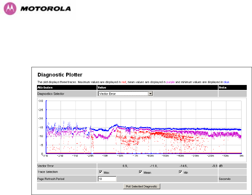
154
8.3.12.1 Diagnostic Plotter
New for the PTP 600 Series is the system administration diagnostic plotter facility see 1151HFigure
87.
Figure 87 - Diagnostic Plotter
The diagnostic plotter allows the system administrator to view the cascading histogram data
in an easily accessible graphical form. The plot always displays three traces, maximum,
minimum and mean by default. The diagnostic selector allows the user to select the various
categories of histogram.
The histograms that are available are:
• Vector Error
• Rx Power
• Tx Power
• Signal Strength Ratio
• Link Loss
• Rx Data Rate
• Tx Data Rate
• Aggregate Data Rate
The diagnostic plotter uses a novel time representation in the x-axis which compresses the
timeline of the plot without sacrificing resolution.
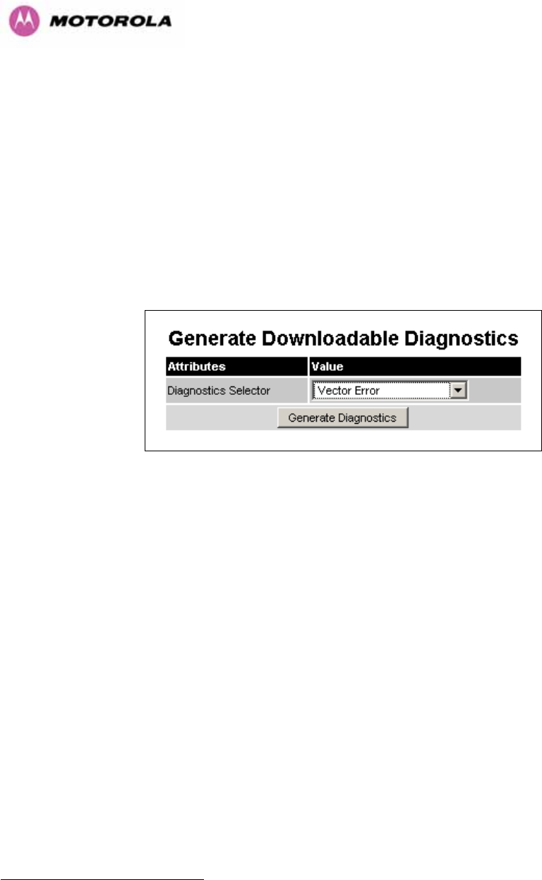
155
The trace selection allows the user to control which traces are plotted.
As with other management pages the page refresh period can be used to interactively monitor the
wireless link.
8.3.12.2 Diagnostics Download
The diagnostics Download page allows the system administrator to download snapshots of
system diagnostics.
Figure 88 - CSV Download
The following diagnostics are available:
• Vector Error
• Rx Power
• Tx Power
• Signal Strength Ratio V/H
• Link Loss
• Rx Data Rate
• Tx Data Rate
• Aggregate Data Rate
• Receive SNR
• Rx Gain
All diagnostics are extracted from the associated status and statistics web page histograms.
They are translated in a CSV file containing at most 578422F
23 entries.
23 5784 entries comprises 3600 entries for the first hour, 1440 entries for the next 24 hours and 744 entries for the next 31
days.
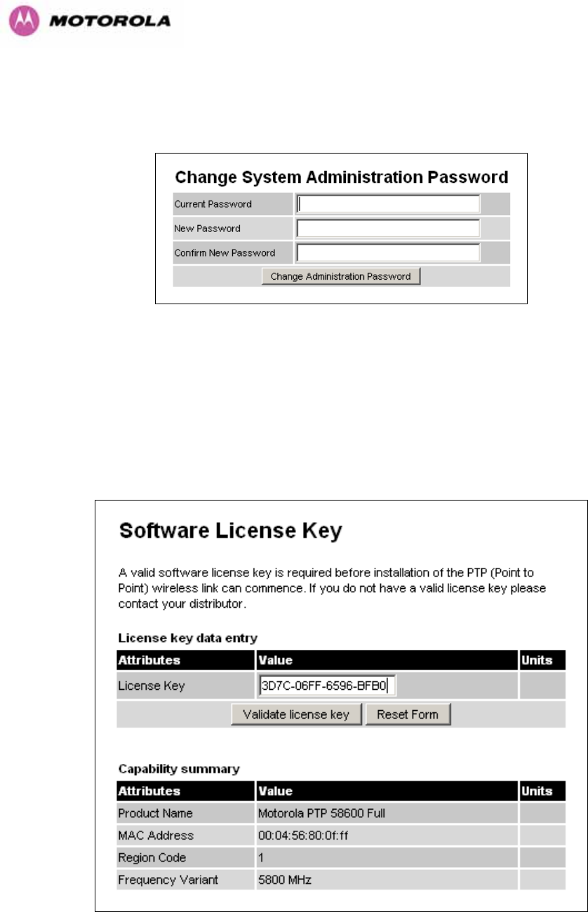
156
8.3.13 Change System Administration Password
This page (1152HFigure 89) is used to change the password for the system administration (The
factory default is blank).
Figure 89 - Password Change
To change the password any combination of alphanumeric characters, up to 31 characters in
length, can be used.
8.3.14 License Key
The License Key data entry page allows the system administrator to update the 600 Series
bridge license key. 1153HFigure 90 shows a sample license key data entry page.
Figure 90 - Software License Key Data Entry
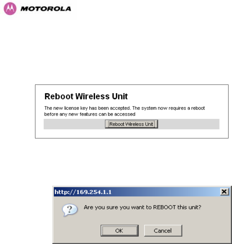
157
The user must enter the license key and click the ‘Validate License Key’ button to check that
the key is valid and program it to non-volatile memory.
If a valid license key is detected then the user will be presented by a system reboot screen.
Figure 91: License Key reboot Screen
The user will then be asked to confirm the reboot (1154HFigure 92).
Figure 92 - Reboot Confirmation Pop Up
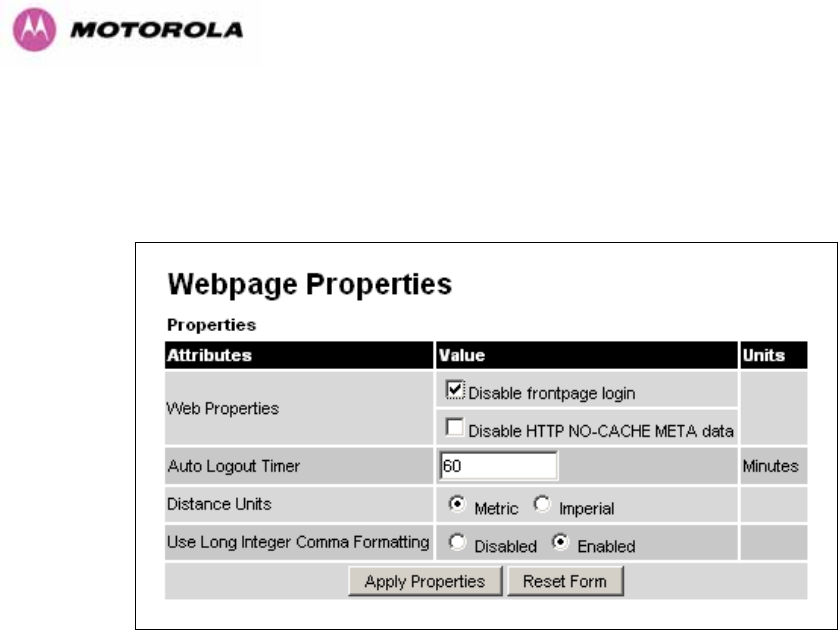
158
8.3.15 Properties
The web page properties screen allows the user to configure the web page interface.
Figure 93 – Properties
WEB Properties: Disable Front Page Login Allows access to homepage and status page
web pages without forcing a login as the system administrator.
WEB Properties: Disable HP NO-CACHE META data: Removes the HTTP NO-CACHE
META clause from all dynamically created web pages.
Auto Logout Timer Configures the time, in minutes, when the system administrator is
automatically logged out if no web page activity is detected.
Distance Units Swaps the default metric display of distance in to imperial units, for example
km to Miles.
Use Long Integer Comma Formatting Changes the format of long integers from 1000000 to
1,000,000.
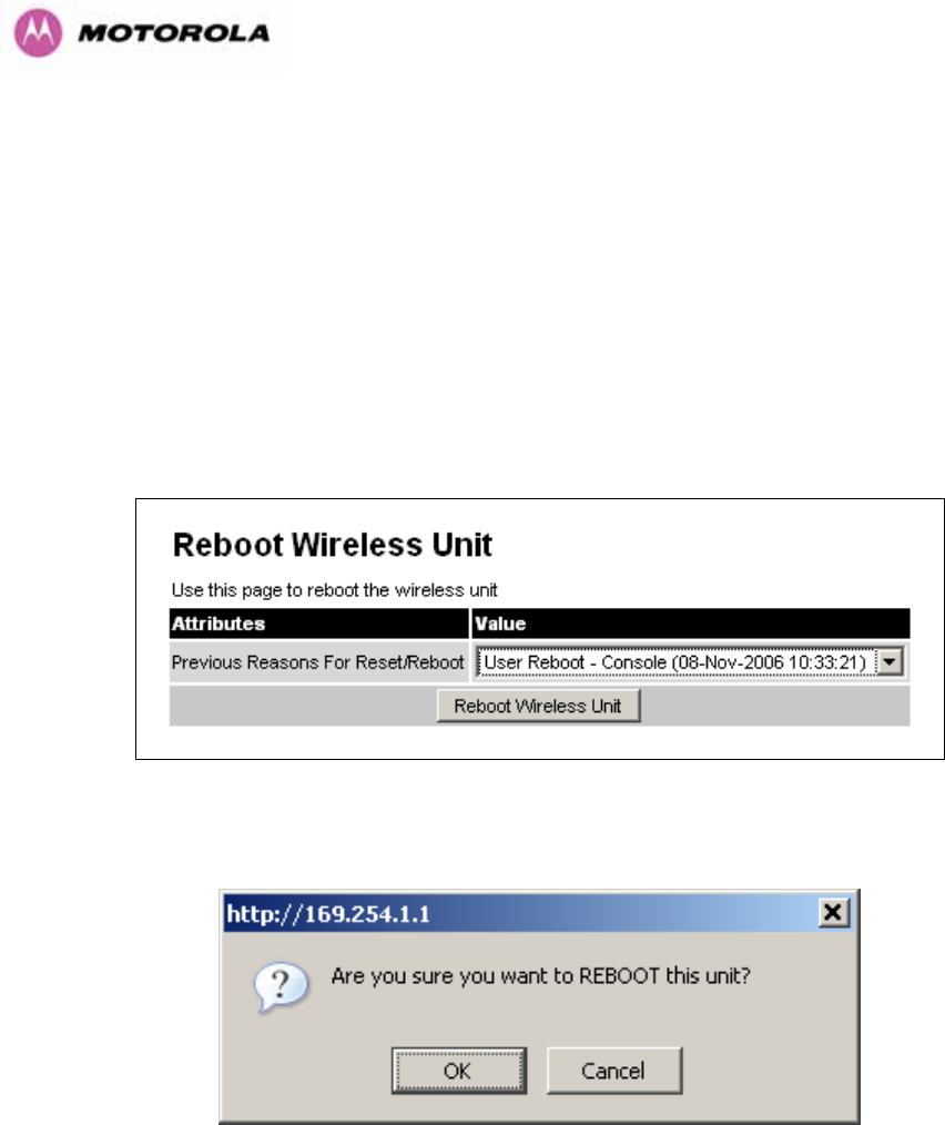
159
8.3.16 Reboot
The reboot page allows the system administrator to perform commanded reboots of the
wireless unit. The reboot page also allows the system administrator to view a list of past
reboot reasons. The “Previous Reasons For Reset/Reboot” field has been implemented as a
drop down selection box, where the latest reason for reboot is located at the top of the list.
If the SNTP service from the remote management section above is active, or the system time
has been set, then the command reboot reason will be accompanied by the date and time at
which the reboot occurred.
Figure 94 - System Reboot
Figure 95 - Reboot Confirmation Pop Up

160
9 Recovery Mode
The Motorola PTP 600 point-to-point wireless Ethernet bridges have a special mode of
operation that allows the user to recover a unit from configuration errors or software image
corruption.
Recovery mode is entered by depressing the Recovery Switch located on the underside of
the PIDU Plus while applying mains power, as shown in Section 1155H3.3.2. The Recovery Switch
should be held in the depressed state for between 10 and 20 seconds after the application of
mains power. The Ethernet LED will flash with 10 double flashes at power up.
When in recovery mode the user will be able to access the unit via the Ethernet interface. The
Ethernet interface will have it’s IP address set to 169.254.1.1 (or 10.10.10.10). On connection
to a unit in recovery mode the following screen is displayed (1156HFigure 96):
Figure 96 - Recovery Mode Warning Page
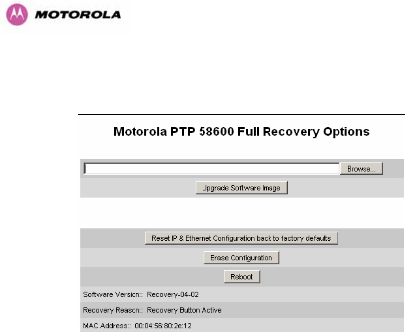
161
Clicking on the warning page image will take the user on to the Recovery Option Page
(1157HFigure 97).
Figure 97 - Recovery Options Page
The recovery options available are:
Upgrade Software Image: This allows the user to reload a software image. This may be the
original image if software corruption is suspected or a step back to an old image if an
incorrect image has just been loaded.
Reset IP & Ethernet Configuration back to factory defaults: This allows the user to reset
the unit back to the factory defaults:
o IP Address 169.254.1.1 (or 10.10.10.10)
o Netmask 255.255.0.0
o Gateway 169.254.1.0
o Ethernet Interface Auto-negotiate, Auto-MDI/MDIX
Erase Configuration: This allows the user to erase the unit’s entire configuration. Executing
this option will also erase factory settings such as target MAC address, range setting, license
key, etc.
Reboot: This allows the user to reboot the unit. This option must be executed after resetting
the IP & Ethernet configuration or erasing the configuration detailed above.
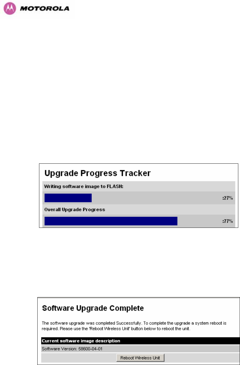
162
Software Version: This is the software version of the recovery operating system permanently
installed during manufacture.
Recovery Reason: Indicates the reason the unit is operating in Recovery mode. Possible
reasons are “Recovery button active” or “Invalid or corrupt image”
MAC Address: The MAC address shown here is the MAC address of the unit programmed
during manufacture.
9.1 Upgrade Software Image
The first step (1158HFigure 97) is to use the ‘Browse’ button to locate the software image to be
downloaded. Once located the user should press the “Upgrade Software Image” button to
start the software download process.
During software download, progress is indicated by a pair of progress bars (1159HFigure 98).
Figure 98 - Software Download Progress Indicator Page
When the download is complete a page is displayed indicating the status of the software
download (1160HFigure 99).
Figure 99 - Software Download Complete Page
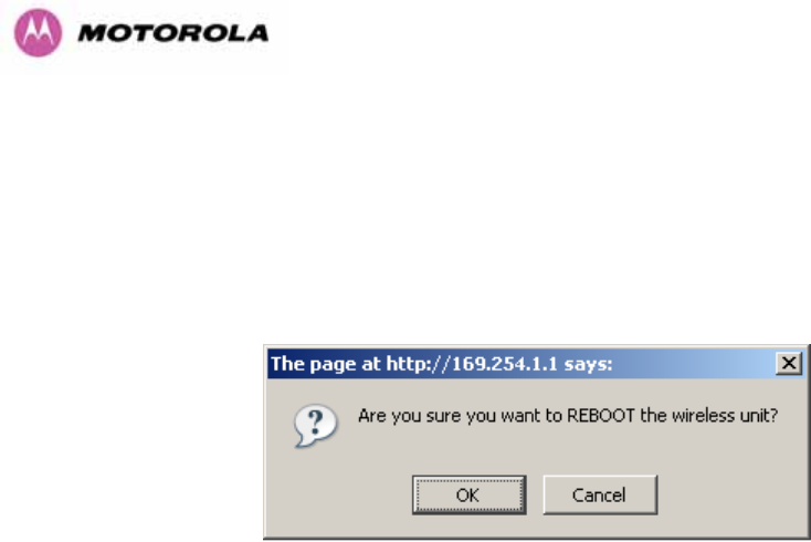
163
After carefully checking that correct image has been downloaded the user should reboot the
unit by pressing the “Reboot Wireless Unit” button. The user will then be presented with a pop
up box asking them to confirm the action (1161HFigure 100)
Figure 100 - Reboot Confirmation Pop Up
The unit will now reboot. Providing the unit configuration is still intact the unit should restart in
normal operational mode and the link should recover. Should the unit or link fail to recover the
user should refer to Section 1162H10.
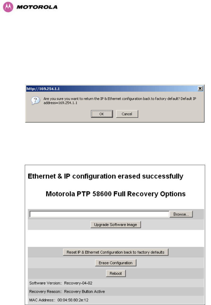
164
9.2 Reset IP & Ethernet Configuration
To reset IP & Ethernet configuration back to factory defaults the user should press the “Reset
IP & Ethernet Configuration back to factory defaults” button on the “Recovery Options” page
(1163H1164HFigure 97). The user will now be presented with a pop up box asking them to confirm the
action (1165HFigure 101).
Figure 101 - Confirm Reset to Factory Default Pop Up
On confirmation the following page will be displayed (1166HFigure 102). The user should now
reboot the unit by pressing the “Reboot” button.
Figure 102 - IP and Ethernet Erased Successfully page
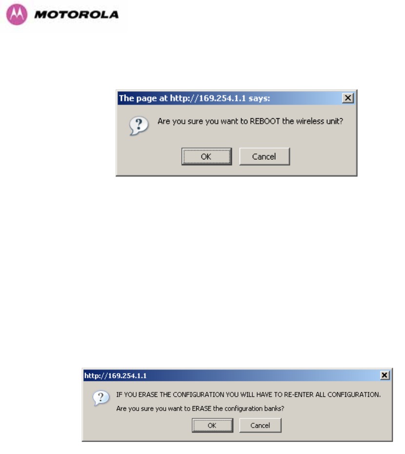
165
The user will now be presented with a pop up box asking them to confirm the action (1167HFigure
103)
Figure 103 - Reboot Confirmation Pop Up
The unit will now reboot. The unit should now start up in normal mode but with the IP address
set to 169.254.1.1 and the Ethernet interface set to auto-negotiate and auto-MDI/MDIX.
Should the unit fail to start up the user should refer to Section 1168H10.
9.3 Erase Configuration
To erase the unit’s configuration the user should press the “Erase Configuration” button on
the “Recovery Options” page (1169HFigure 97). The user will now be presented with a pop up box
asking them to confirm the action (1170HFigure 104).
Figure 104 - Confirm Erase Configuration Pop Up
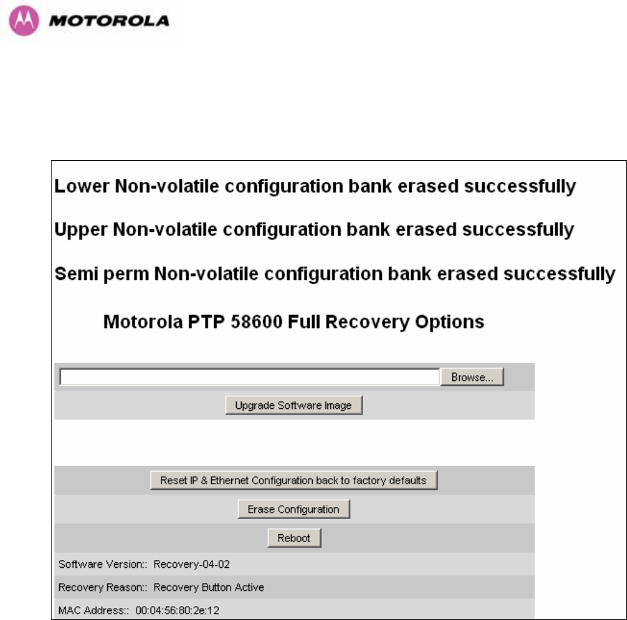
166
On confirmation the following page will be displayed (1171HFigure 105). The user should now
reboot the unit by pressing the “Reboot” button.
Figure 105 - Erase Configuration Successful Page
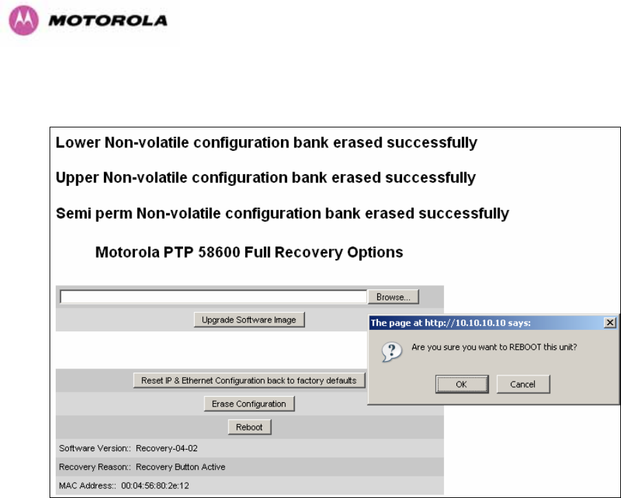
167
The user will now be presented with a pop up box asking them to confirm the action (1172HFigure
106)
Figure 106 – Erase Configuration - Reboot Confirmation Pop Up
The unit will now reboot. The unit should now start up in normal mode but with all
configuration erased. Should the unit fail to start up the user should refer to Section 1173H10.
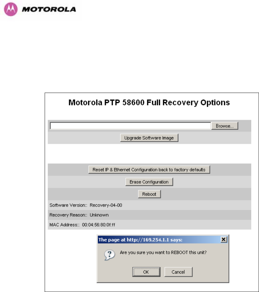
168
9.4 Reboot
To erase the unit’s configuration the user should press the “Reboot” button on the “Recovery
Options” page (1174HFigure 97). The user will now be presented with a pop up box asking them to
confirm the action (1175HFigure 107).
Figure 107 – Recovery - Reboot Confirmation Pop Up
The unit will now reboot. The unit should now start up in normal operational mode. Should the
unit fail to start up the user should refer to Section 1176H10.
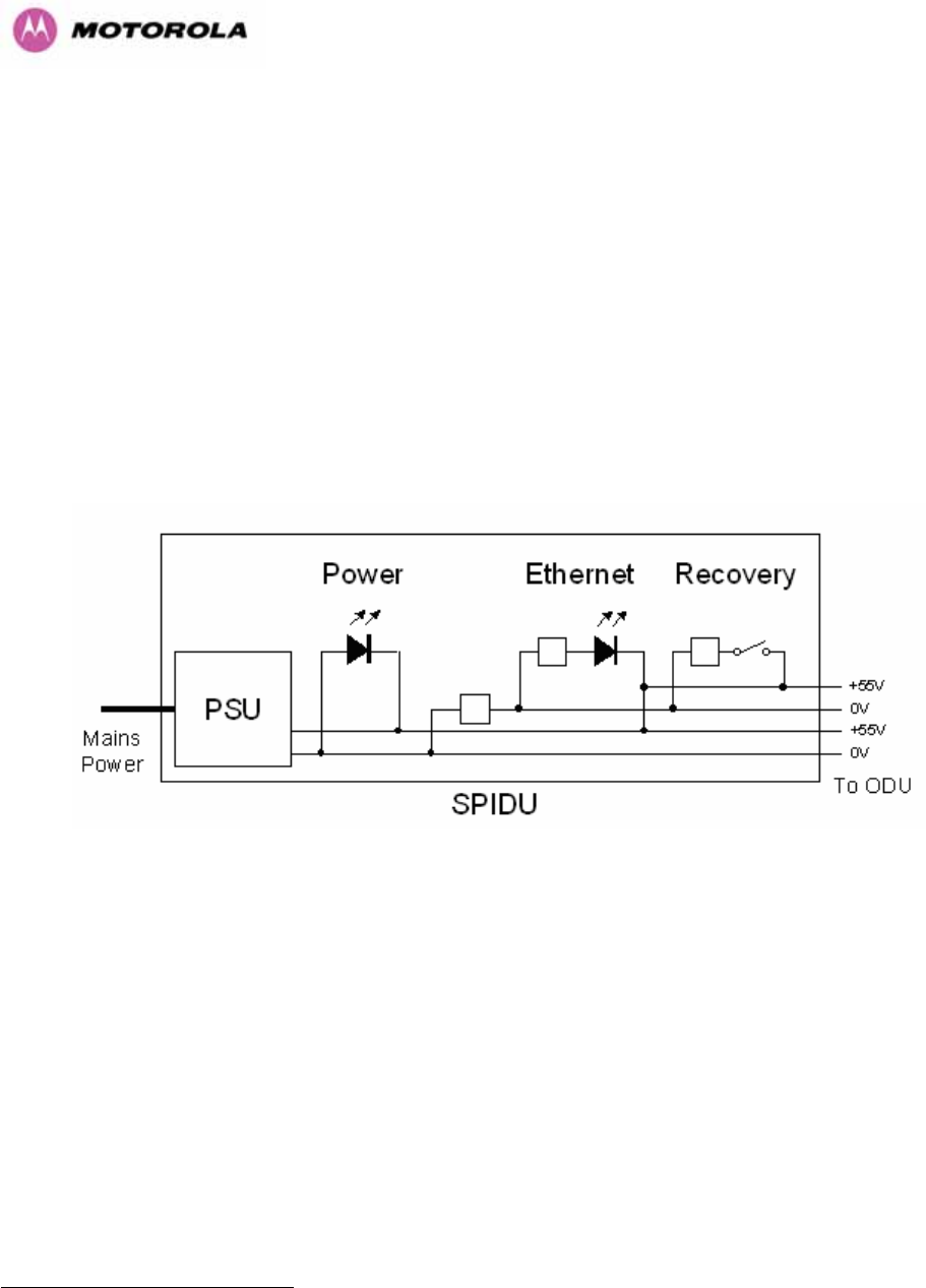
169
10 Fault Finding
If communication has been lost with the unit at the near end of the link then there may be a
hardware fault with the wiring, network or hardware. Go to the hardware section below. If
communication with the far end of the link is lost then go to the radio section below.
10.1 Hardware
If there are problems suspected with the link hardware the following procedure is
recommended.
The following diagram illustrates the main system connections:
Figure 108 - Main System Connections
10.1.1 Power
Check the power LED at each end of the link. If the power lights are illuminated go to the
Ethernet section below. If at either end they are not illuminated then23F
24 check the Ethernet
LED.
If neither is illuminated then there is no voltage on the power wires to the ODU.
• Check that the mains power is connected and switched on.
• Check that the lamp illuminates if the ODU connector is disconnected at the PIDU Plus
(Remove the PIDU Plus cover).
24 The power indicator LED should be continually illuminated.

170
If it does illuminate then either the ODU is drawing too much current, or the power wiring to
the ODU is short circuit or the PSU is supplying insufficient power. The likely fault can be
determined by removing the jumper (J906), found inside the removable cover of the PIDU
Plus, and measuring the current taken with an ammeter placed across the 2 jumper pins. This
is normally 10mA without the ODU connected and 300mA to 1A when the ODU is connected.
If it does not illuminate then recheck that power is applied to the PIDU Plus by measuring the
voltage across +55V and 0V pads inside the removable cover in the PIDU Plus. Check that
the PIDU Plus is not short circuit by measuring the impedance across the Power connector. Is
the lamp faulty?
10.1.2 Ethernet
The Ethernet LED is driven from the ODU processor and thus is capable of informing you of
many conditions using different flash sequences. If the Ethernet indicator does not illuminate
at all there are four possible conditions.
• There is no power reaching the ODU because of a wiring fault
• The ODU is faulty
• The PIDU Plus is faulty
• The Ethernet network side is faulty
Look at the following table to check the LED response for power up, disconnect the power
and reapply and note what happens.
Differentiating between 1-3 and 4 can be achieved by removing the power for 1 second.
Watch the Ethernet indicator for 1 minute, if it never flashes then the problem is 1-3. Take the
jumper (J906) out of the PIDU Plus and check the current taken by the ODU. This should be
300mA to 1A when starting to run normally.
If the Ethernet indicator flashes to begin with but then stops flashing, the ODU is powered and
software loaded but Ethernet connectivity has been lost between the ODU and the users
connected equipment. All Ethernet connections should be rechecked.

171
Power Indoor Unit LED check chart:
Mode Green LED
Yellow LED No Ethernet
Cable Connected
Yellow LED
Ethernet Cable
Connected between
PIDU Plus and
NIC/Switch/Hub
No Power Applied Off Off Off
Power Applied On
Will flash once per second
regularly approximately 30
seconds after power
applied for 10 seconds then
will go out and stay out
Will flash once per
second regularly
approximately 30
seconds after power
applied for 10
seconds then operate
as Ethernet
Link/Activity LED
Valid Ethernet Link
and no traffic On N/A Will be on solid for a
valid link.
Valid Ethernet Link
with traffic On N/A
Will be on solid, but
will blink randomly as
traffic passes through
Recovery Switch
Pressed and held
for >10 seconds
from power on
(Recovery is
pressed while
power is applied)
On
Off while switch pressed.
Approximately 30 seconds after releasing the
switch, flashes twice per second regularly for 10
seconds, then boots in “Recovery Mode”
While in “Recovery Mode” the unit will only be
accessible via the IP address 10.10.10.10 or
169.254.1.1.
10.1.3 Checking your wiring
If the above procedures fail to diagnose the issue you may have a wiring fault. Unplug the
RJ45 from the PIDU+ and check the following resistances at the RJ45:
1. Check the cable resistance between pins 1 & 2, 3 & 6, 4 & 5 and 7 & 8 at the RJ45.
Check against column 2 in 1177HTable 18.
2. Check the cable resistance between pins 1 & 3 at the RJ45. Check against column 3 in
1178HTable 18.
3. Check the cable resistance between pins 4 & 7 at the RJ45. Check against column 4 in
1179HTable 18.
4. Ensure that there is greater than 100K ohms between pins 1 & 8 for all cable lengths.

172
5. Ensure that there is greater than 100K ohms between pin 1 and ODU ground for all cable
lengths.
6. Ensure that there is greater than 100K ohms between pin 8 and ODU ground for all cable
lengths
CAT-5 Length
(Meters) Resistance
between pins
1 & 2, 3 & 6 , 4 & 5
and pins 7 & 8
(ohms)
Resistance
between pins
1 & 3
(ohms)
Resistance
between pins
4 & 7
(ohms)
0 0.8 1.0 1.6
10 2.5 2.7 3.3
20 4.2 4.4 5.0
30 5.9 6.1 6.7
40 7.6 7.8 8.4
50 9.3 9.5 10.1
60 11.0 11.2 11.8
70 12.7 12.9 13.5
80 14.4 14.6 15.2
90 16.1 16.3 16.9
100 17.8 18.0 18.6
Table 18 - Resistance Table Referenced To The RJ45 at the PIDU+
10.2 Radio
10.2.1 No Activity
If communication over the radio link has been lost and the unit at the other end of the link can
be managed on its local network, the following procedure should be adopted:
If there is no wireless activity then the configuration should be checked. It is essential that the
following items are correct:
• Check for Alarm conditions on Home page
• Check that the software at each end of the link is the same version
• Check that the Target Mac address has not been mis-configured at each end of the link.
• Check Range
• Check Tx Power

173
• Check License key
• Check Master Slave
• Check that the link has not been further obscured or the ODU misaligned.
• Check the DFS page at each end of the link and establish that there is a quiet wireless
channel to use.
If there are no faults found in the configuration and there is absolutely no wireless signal retry
the installation procedure. If this doesn’t work then the ODU may be faulty.
10.2.2 Some Activity
If there is some activity but the link is unreliable or doesn’t achieve the data rates required
then:
• Check that the interference has not increased using the i-DFS measurements
• If a quieter channel is available check that it is not barred
• Check that the path loss is low enough for the communication rates required
• Check that the ODU has not become misaligned

174
11 Lightning Protection
EMD (Lightning) damage is not covered under warranty
The recommendations in this user manual when installed correctly give
the user the best protection from the harmful effects of EMD
However 100% protection is neither implied nor possible
11.1 Overview
The idea of lightning protection is to protect structures, equipment and people against
lightning by conducting the lightning current to ground via a separate preferential solid path
and by reducing the electromagnetic field.
The following should be treated as a guide only, the actual degree of lightning protection
required depends on local conditions and weather patterns and applicable local regulations.
Full details of lightning protection methods and requirements can be found in the international
standards IEC 61024-1 and IEC 61312-1, the U.S. National Electric Code ANSI/NFPA No.
70-1984 or section 54 of the Canadian Electric Code.
11.1.1 Lightning Protection Zones
The installation of the ODU can be classified into two different lightning protection zones.
Zone A — In this zone a direct lighting strike is possible.
Zone B — In this zone a direct lightning strike is unusual, but the un-attenuated
electromagnetic field is still present.
The zones are determined using the ‘rolling sphere method’, an imaginary sphere, typically 50
meter in radius is rolled over the structure. All structure points that contact the sphere, (Zone
A) indicate the zone where a direct strike is possible. Similarly points that do not contact the
sphere indicate a zone (zone B) where a direct strike is less likely.

175
The following diagrams (1180HFigure 109 & 1181HFigure 110) show this zoning pictorially:
Equipment mounted in Zone A should be capable of carrying the full lightning current.
Mounting of the ODU in Zone A is not recommended. Mounting in Zone A should only be
carried out observing the rules governing installations in Zone A24F
25 Failure to do so may put
structures, equipment and life at risk.
Equipment mounted in Zone B should be grounded using grounding wire of at least 10 AWG.
This grounding wire should be connected to a grounding rod or the building grounding system
before entry in to building.
The 600 Series bridge ODU grounding point can be found on the bottom of the unit. The 600
Series Bridge is supplied with an appropriate grounding lug for attachment to the ODU.
11.2 Detailed Installation
The recommended components for an installation protected for nearby strikes are:
• Grounding Kits — Andrew Type 223158-2 (481Hhttp://www.andrew.com UT)
• Screened CAT 5e Cable also known as Shielded CAT 5e or CAT 5e STP (Shielded
Twisted Pair)
• NB: Only use Outdoor rated, gel filled CAT5e if it contains a shield.
• Surge Arrestor: Transtector Type ALPU-ORT - 4 per link (482Hwww.transtector.com)
• Grounding Stake
• RJ45 screened connectors
• 8 AWG Grounding Cable – Minimum size, preferably 6 or 4
NOTE: There may be a local regulatory requirement to cross bond the CAT 5e cable at
regular intervals to the mast. This may be as frequent as every 10 meters (33 feet)
25 Local regulations may also require the fitting of the 8 AWG ground wire referred below.
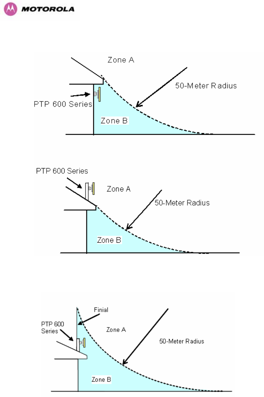
176
Figure 109 - ODU mounted in Zones A & B
Figure 110 - Showing how the use of a Finial enables the ODU to be mounted inside Zone B
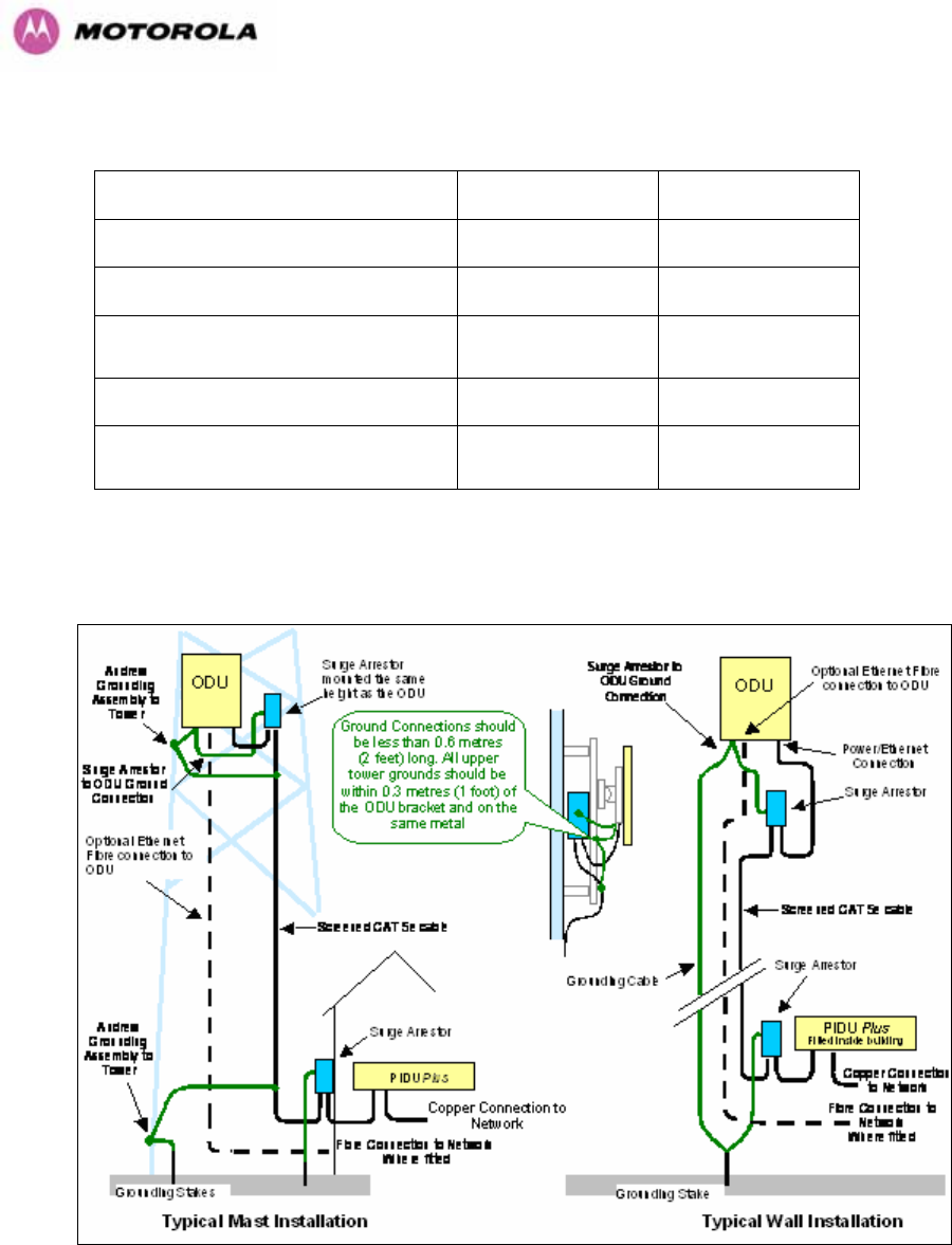
177
Zone A Zone B
Earth ODU Mandatory Mandatory
Screen Cable Mandatory Mandatory
Surge Arrestor Unit at ODU – ALPU-
ORT Mandatory Mandatory
Earth Cable at Building Entry Mandatory Mandatory
Surge Arrestor Unit at Building Entry
– ALPU-ORT Mandatory Mandatory
Table 19 - Protection Requirements
Figure 111 - Diagrammatically showing typical wall and mast installations
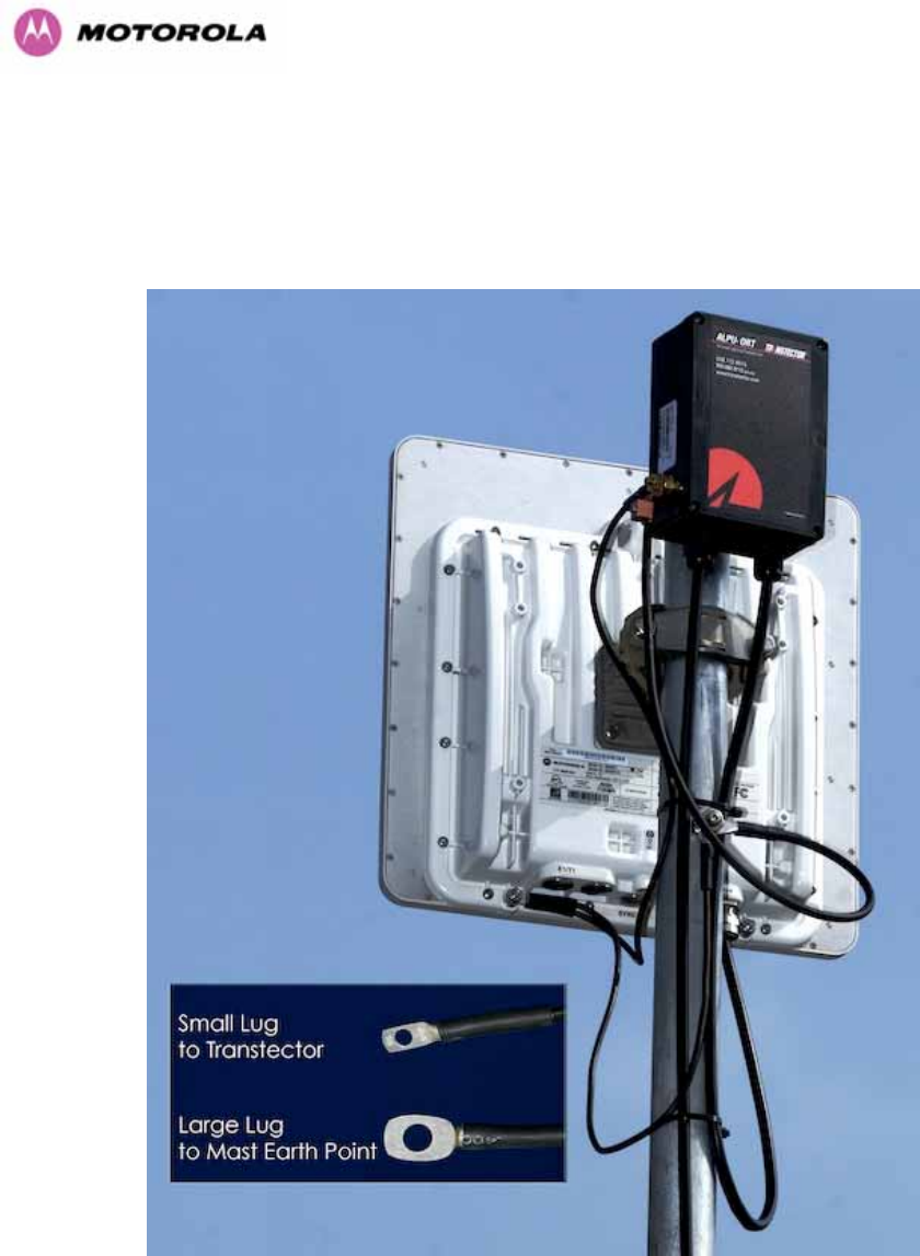
178
A typical installation is shown in 1182HFigure 112 and 1183HFigure 113.
Note: Grounding Points are shown unprotected for clarity. Grounding points should be
adequately weatherproofed to prevent corrosion and possible loss of ground continuity.
Figure 112 - Upper Grounding Configuration
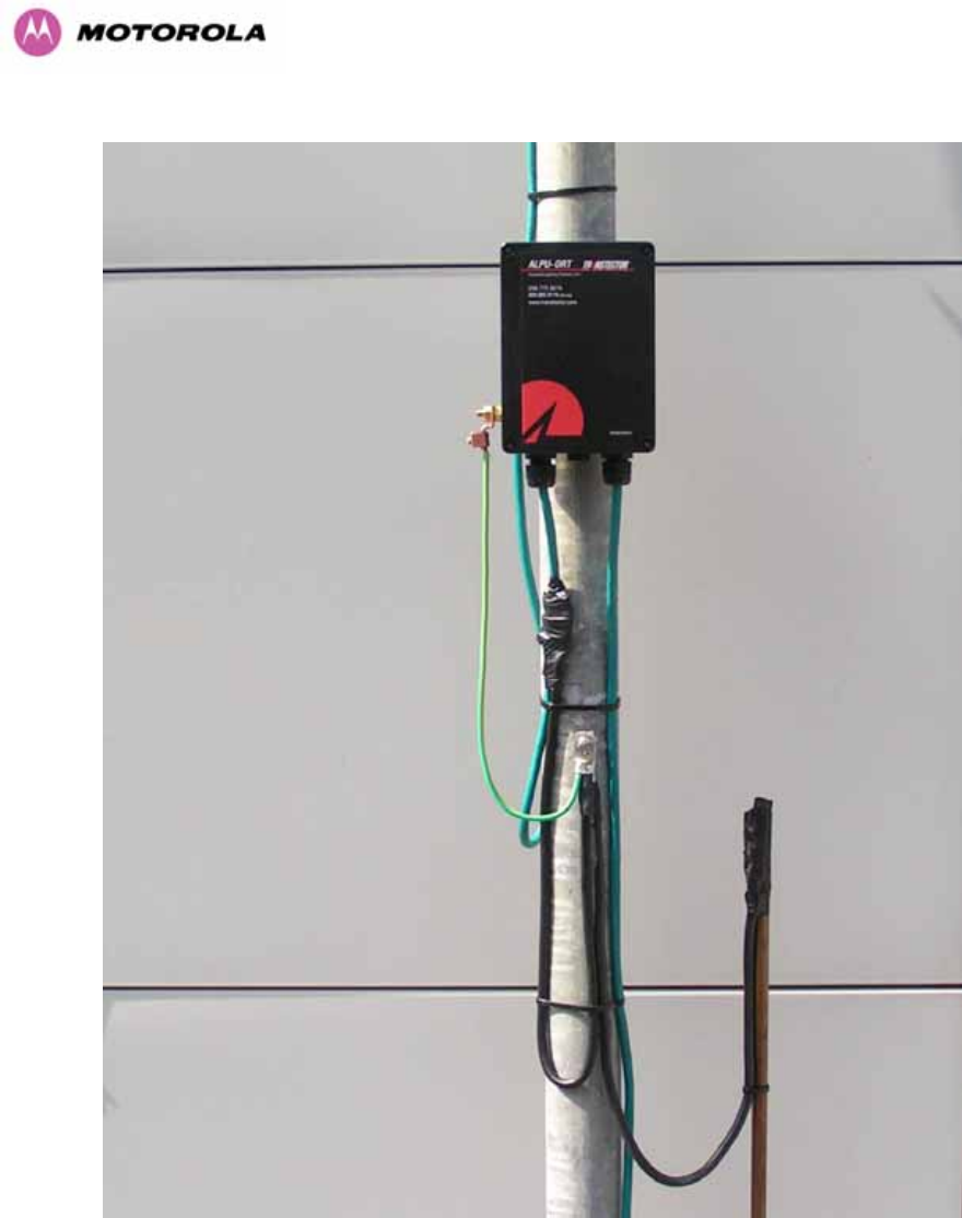
179
Figure 113 - Lower Grounding Configuration
An Andrew Grounding Kit and Surge Arrestor Unit must be located at the ODU and reliably
grounded as shown in Figure 95. There may also be a regulatory requirement to crossbond
the screened CAT-5 at regular intervals up the mast. Refer to local regulatory requirements
for further details.

180
A second Surge Arrestor Unit should be mounted at the building entry point and must be
grounded.
The termination of the CAT-5 Cable into the Surge Arrestor Unit is illustrated in Table, 1184HTable
21 and 1185HFigure 114. The screen from the cable must be terminated into the ground terminal
within the unit to ensure the continuity of the screen. Earth Sleeving should be used to cover
the shield ground connection to prevent internal shorting within the unit.
Terminal Identification Conductor RJ45 Pin
CON3 Pin 1 Orange/White 1
CON3 Pin 2 Orange 2
CON3 Pin 3 Green/White 3
CON3 Pin 6 Green 6
CON1 Pin 4 Blue 4
CON1 Pin 5 Blue/White 5
CON1 Pin 7 Brown/White 7
CON1 Pin 8 Brown 8
Table 20 - Surge Arrestor ALPU-ORT Cable 1 Termination
Terminal Identification Conductor RJ45 Pin
CON4 Pin 1 Orange/White 1
CON4 Pin 2 Orange 2
CON4 Pin 3 Green/White 3
CON4 Pin 6 Green 6
CON2 Pin 4 Blue 4
CON2 Pin 5 Blue/White 5
CON2 Pin 7 Brown/White 7
CON2 Pin 8 Brown 8
Table 21 - Surge Arrestor ALPU-ORT Cable 2 Termination
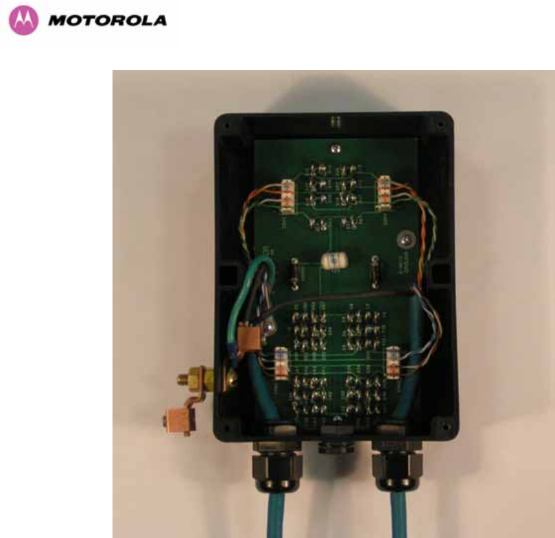
181
Figure 114 - Surge Arrestor ALPU-ORT Connection Illustration
Note: Cable screens have been sleeved.
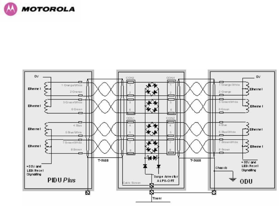
182
11.3 Testing Your Installation
If you have followed the above instructions you will have wired your system to the following
diagram:
Figure 115 - Simplified Circuit Diagram (Only One Transtector Shown For Clarity)
11.3.1 Pre-Power Testing
Before plugging in the RJ45 to the PIDU check the impedances at the RJ45 as described in
1186H10.1.3.
11.3.2 Post-Power Testing
The Correct Operation is as follows
1. Connect the RJ45 to the PIDU and apply power to the PIDU, the power LED should
illuminate continuously.
2. 45 seconds after powering, the Ethernet LED should be observed starting with 10 slow
flashes.
3. If there is a network connection the Ethernet LED will then show Ethernet activity.
The Ethernet LED does not flash 10 times
Failure of the Ethernet LED to illuminate can be due to wiring to pins 4&5 and 7&8 being
incorrect, for example if the wiring to pins 4 and 7 are crossed.

183
The Ethernet LED flashes ten times but irregularly
Irregularly flashing, seen as a short gap followed by a long gap, indicates that the ODU has
booted in recovery mode. This may be due to either the installation wiring or a corrupted main
code image in the ODU.
The Ethernet LED flashes ten times but does not show Ethernet activity
Failure of the Ethernet LED to show Ethernet activity can be due to wiring to pins 1&2 and
3&6 being incorrect, for example if the wiring to pins 1 and 3 are crossed.
The Ethernet connection to the network is only 10/100 BaseT, when 1000 BaseT was
expected
It is likely there is a fault with the wiring to pins 4&5 and 7&8.

184
12 Wind Loading
12.1 General
Antennas and electronic equipment mounted on towers or pole mounted on buildings will
subject the mounting structure to lateral forces when there is appreciable wind. Antennas are
normally specified by the amount of force (in pounds) for specific wind strengths.
The magnitude of the force depends on both the wind strength and size of the antenna.
12.2 Calculation of Lateral Force
The 600 Series bridge with or without the integral antenna is essentially a flat structure and so
the magnitude of the lateral force can be estimated from:
Force (in pounds) = 0.0042 . A . v2
Where A is the surface area in square feet and v is the wind speed in miles per hour.
The lateral force produced by a single 600 Series bridge (integrated or connectorized model)
at different wind speeds is shown in 1187HTable 22 and 1188HTable 23.
Lateral Force (Pound) at wind speed (mph)
Largest Surface
Area (sq ft)
80 100 120 140 150
PTP 600 Series
Bridge - Integrated
1.36 37 57 82 112 129
PTP 600 Series
Bridge -
Connectorized
1.00 27 42 60 82 95
Table 22 - Lateral Force – Imperial

185
Lateral Force (kg) at wind speed (m/s)
Largest Surface
Area (sq m)
30 40 50 60 70
PTP 600 Series
Bridge - Integrated
0.130 12 22 34 49 66
PTP 600 Series
Bridge -
Connectorized
0.093 9 16 24 35 48
Table 23 - Lateral Force – Metric
Note: When the connectorized version of 600 Series bridge is used with external antennas,
the figures from the antenna manufacturer for lateral force should be included to calculate to
total loading on the mounting structure.
12.3 Capabilities of the PTP 600 Series Bridges
The structure and mounting brackets of the PTP Series systems are capable of withstanding
wind speeds up to 151mph (242 kph). The installer should ensure that the structure to which
the 600 Series Bridge is fixed to is also capable of withstanding the prevalent wind speeds
and loads.
12.4 Wind Speed Statistics
Installers are recommended to contact the national meteorological office for the country
concerned to identify the likely wind speeds prevalent at the proposed location. This will
enable the installer to estimate the total wind loading on the support structures.
Examples of the sort of statistics that are available are:
USA - Reported Fastest Single Wind Velocities for Selected U.S. Cities
(Source: National Weather Service)
City, State Wind Velocity
(mph)
Bismarck, North Dakota 72
Buffalo, New York 91

186
Chicago, Illinois 87
Hatteras, North Carolina 110
Miami, Florida 132
New York, New York 99
Pensacola, Florida 114
UK Meteorological Office, 483Hwww.meto.gov.uk
Peak wind speed contour maps can be found as Fig 3a/3b at:
484Hhttp://www.meto.gov.uk/education/historic/1987.html

187
13 PTP 600 Series Bridge – Connectorized Model
13.1 Scope
This section details the changes and additional features relevant to the connectorized version
of the PTP 600 Series systems, OS 58C.
13.2 Product Description
13.2.1 Hardware
The Connectorized PTP 600 Series Bridge is a variant designed to provide the system
integrator and installer with the ability to provide extra capability to cope with very difficult
radio links compared to the PTP 600 Series Integrated model. The variant allows the use of a
variety of externally mounted antennas, either Flat Plate or Dish, which have higher gains
than provided by the integrated antenna that is normally used.
Figure 116 – Connectorized 600 Series Bridge Outdoor Unit

188
13.2.2 Antenna Choices – 5.8 GHz
The integrated antenna has a gain of 23 dBi.
In non-FCC regions antenna choice is not restricted but any region specific EIRP limit should
be obeyed, see 1189HTable 6 in Section 1190H5.3 “Region Codes”
In FCC regions external antennas from the list in Section 1191H13.7 “1192HAntennas for USA / Canada”
can be used with the Connectorized version of the 600 Series Bridge. These are approved by
the FCC for use with the product and are basically constrained by the following limits:
• Single Polarization Flat Plate Antennas – up to 28dBi per antenna.
• Single/Dual Polarization Parabolic Dish Antennas – up to 37.7dBi per polarization or
antenna.
In FCC regions when using external antennas – cable loss between the connectorized
version of the 600 Series Bridge and the antenna ports must not be less than 1.2dB
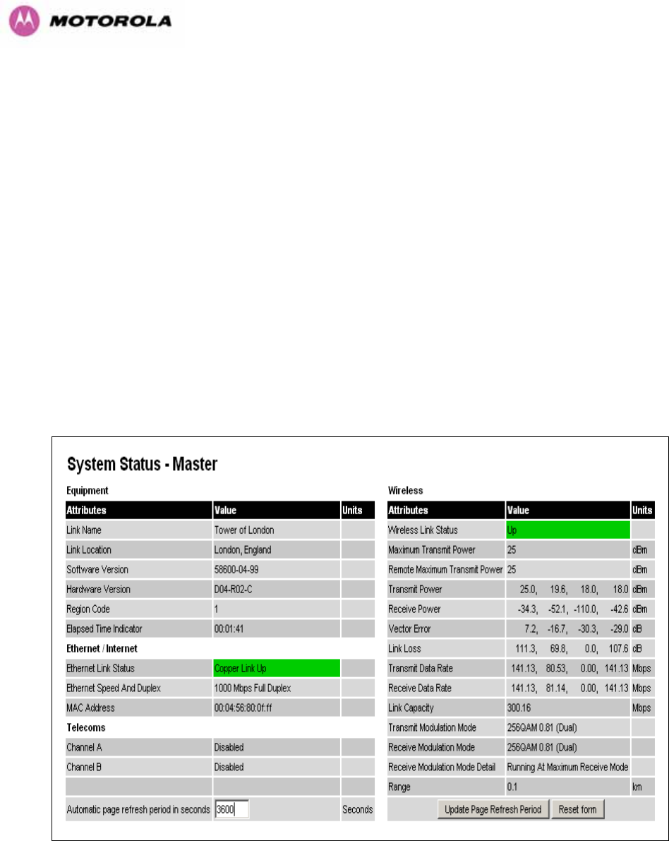
189
13.3 Software/Features
The variant operates in the same way as the basic 600 Series bridge and is released initially
with the feature set of the Connectorized 600 Series bridge. The areas where the
functionality is modified are:
13.3.1 Status Page
The link loss calculation presented on the Status Page of the management interface has to be
modified to allow for the increased antenna gains at each end of the link. The manufacturing
process of the Connectorized 600 Series Bridge configures the standard hardware of the unit
for use with external antennas. The installer is prompted, as part of the installation process, to
enter the gain of the external antenna(s) and cable losses at each end of the link.
Peer-to-peer messaging is used to pass the effective antenna gain to each end of the link so
that the link loss calculations can be correctly computed.
Figure 117 - Connectorized 600 Series bridge Status Page
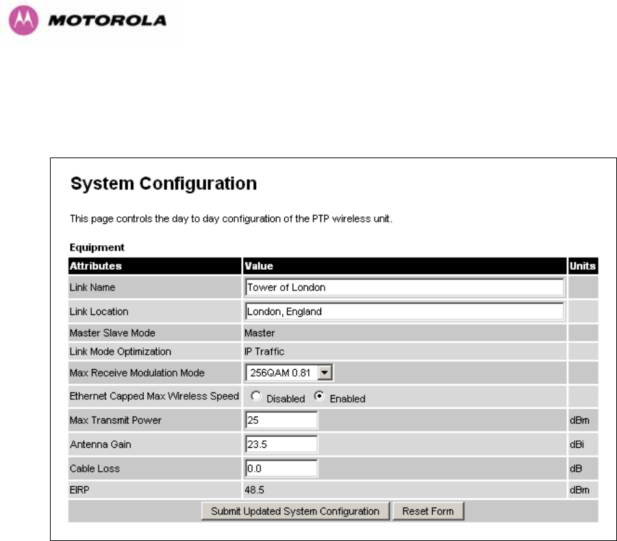
190
13.3.2 Configuration Pages
The amended Configuration web page is shown below as 1193HFigure 118.
Figure 118 - Connectorized 600 Series bridge ‘System Configuration’ Page
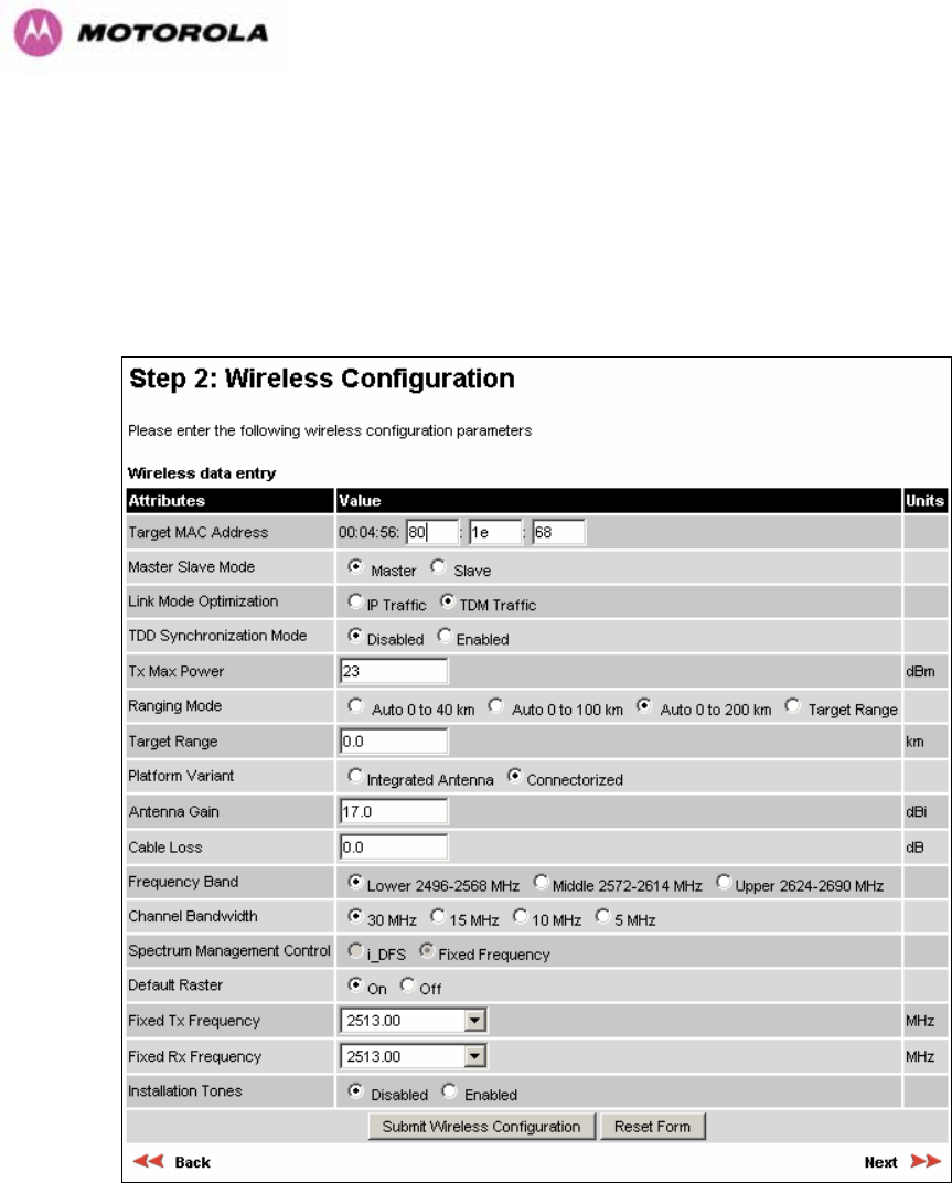
191
13.3.3 Installation Pages
The installer is prompted to enter the Antenna Gain and Cable Loss (Connectorized PTP 600
Series Bridge to antenna) at each end of the link. The Installation Page(s) is shown as 1194HFigure
119 to 1195HFigure 121.
Figure 119 - Connectorized PTP 600 Series Bridge ‘Installation Wizard’ Page
Antenna Gain: Gain of the antenna you are connecting to the unit, see 1196HTable 25.
Cable Loss: Loss in the cable between the ODU and the antenna. Note: In the event that
there is a significant difference in length of the antenna cables for the two antenna ports, then
the average value should be entered.
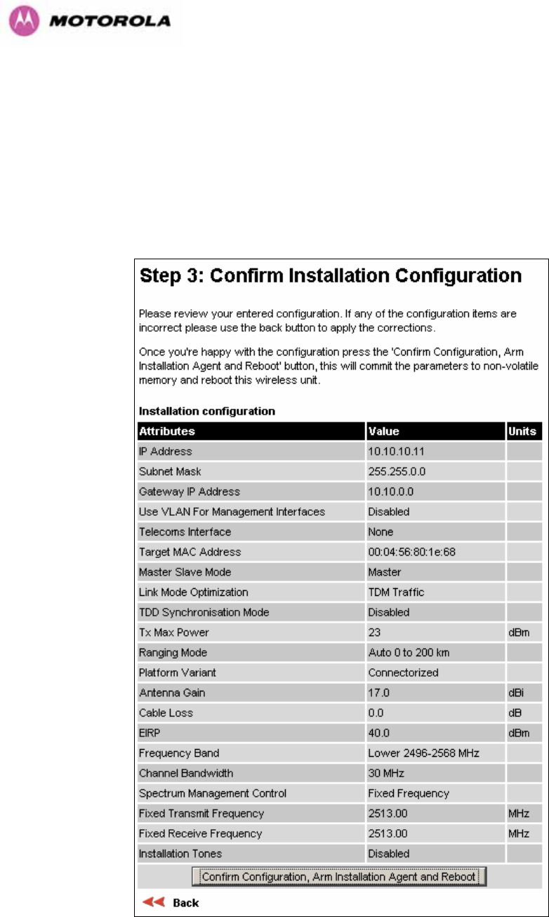
192
Spectrum Management Control: Is used to configure the 600 Series Bridge Spectrum
Management features, see Section 1197H8.3.7 for more details. iDFS is the abbreviation for
intelligent Dynamic Frequency Selection, which continually monitors the 5.8 GHz spectrum
looking for the channel with the lowest level of on channel and co-channel interference. Fixed
frequency mode allows the installer to fix the Transmit and receive frequencies on the units.
The frequencies may be configured symmetrically or asymmetrically.
Figure 120 - Connectorized 600 Series bridge ‘Confirm Installation’ Page
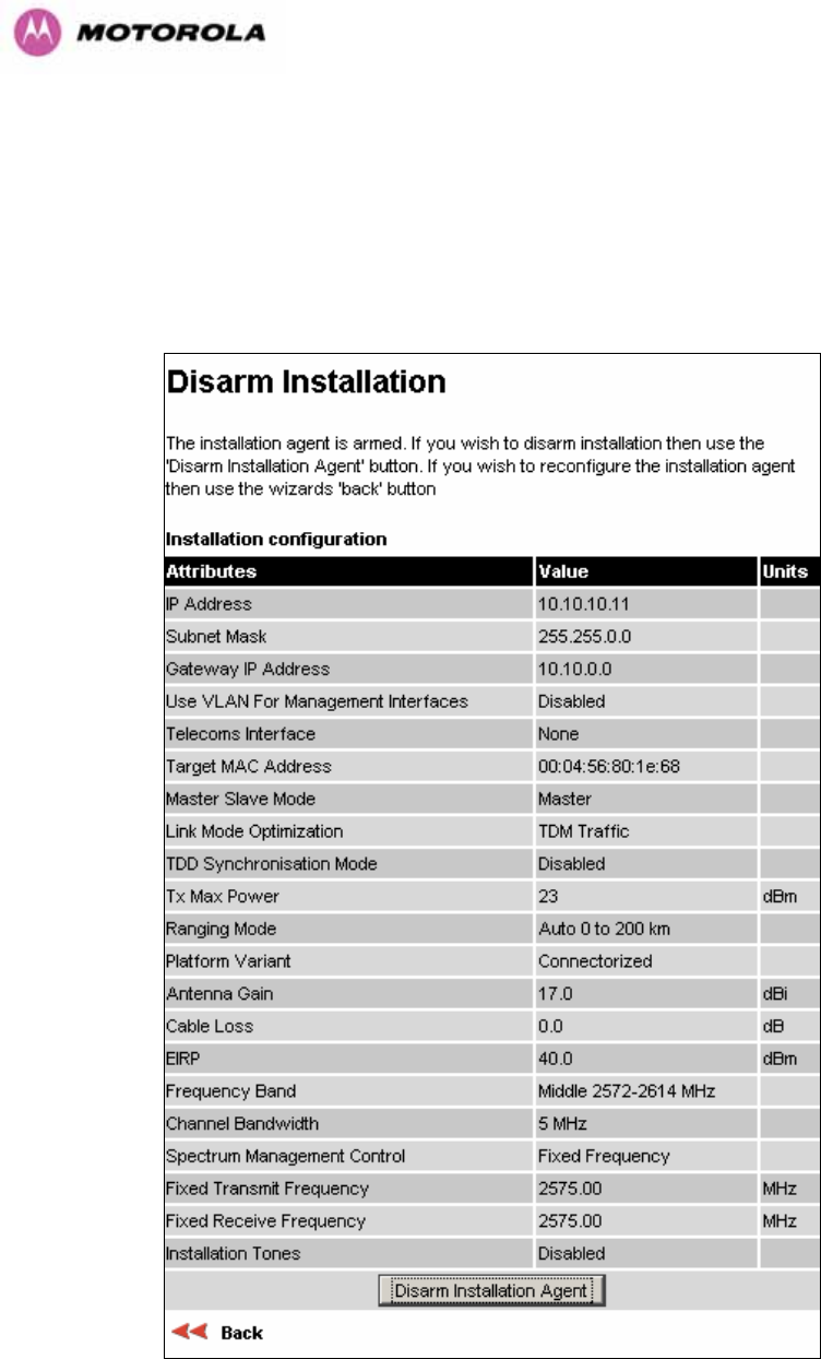
193
EIRP The Confirm Installation Page displays the EIRP (Effective Isotropic Radiated Power),
which describes the strength of the radio signal leaving the wireless unit. This allows the
operator to verify that their link configuration (Max Transmit Power, Antenna Gain and Cable
Loss) do not cause the link to exceed any applicable regulatory limit.
Figure 121 - Connectorized 600 Series bridge ‘Disarm Installation’ Page

194
13.4 Deployment Considerations
The majority of radio links can be successfully deployed with the 600 Series bridge. It should
only be necessary to use external antennas where the Link Budget Calculator indicates
marginal performance for a specific link – for example when the link is heavily obscured by
dense woodland on an NLOS link or extremely long LOS links (>80km or > 50 miles) over
water.
The external antennas can be either dual-polarization (as the integrated antenna) or two
single polarized antennas can be used in a spatially diverse configuration. It is expected that
the dual-polarization antennas would normally be used to simplify the installation process;
spatially diverse antennas may provide additional fade margin on very long LOS links where
there is evidence of correlation of the fading characteristics on Vertical and Horizontal
polarizations.
Dual polarization antennas (with a gain greater than the integrated antenna) are currently only
available in parabolic dish form.
13.5 Link Budget
An estimate of the link budget for a specific application can be obtained by using the Motorola
Systems link estimation tools. For more information see the Motorola web site.
13.6 Regulatory Issues
In countries where FCC regulations are not relevant, installations should conform to any
applicable local regulations for the Equivalent Isotropic Radiated Power (EIRP).
Ensuring compliance becomes more complex when the connectorized unit is used with
external antennas which may be locally sourced. With higher gain external antennas fitted,
the Maximum Transmit power may need to be reduced for operation in specific countries.
See 1198HTable 6 in Section 1199H5.3 for any EIRP restrictions that may apply in your region.
13.6.1 Antenna Choice (FCC Regions Only)
The antennas which can be deployed with the Connectorized 600 Series Bridge are shown in
1200HTable 25.

195
13.6.2 Cable Losses (FCC Regions Only)
The FCC approval for the product is based on tests with a cable loss between the units of
approximately 1.2dB at 5.8GHz. The use of lower cable losses would result in the installation
being outside the FCC rules.
As an indication, 1.2dB of cable loss corresponds to the following cable lengths excluding
connector losses (source: Times Microwave).
Length for 1.2dB Cable Loss at 5.8GHz
Cable
(ft) (m)
LMR100 1.9 0.6
LMR200 4.6 1.4
LMR300 7.25 2.2
LMR400 11.1 3.4
LMR600 16.5 5.0
Table 24 - Cable Losses per Length
13.7 Antennas for USA / Canada
Manufacturer Antenna Type Gain
(dBi) Flat
Plate Paraboli
c Dish
Andrew Andrew 1-foot Flat Panel, FPA5250D12-N
(23.6dBi)
23.6 Y
Andrew Andrew 2-foot Flat Panel, FPA5250D24-N
(28dBi)
28 Y
Gabriel Gabriel 1-foot Flat Panel, DFPD1-52 (23.5dBi) 23.5 Y
Gabriel Gabriel 2-foot Flat Panel, DFPD2-52 (28dBi) 28 Y
MTI MTI 17 inch Diamond Flat Panel, MT-485009
(23dBi)
23 Y
MTI MTI 15 inch Dual-Pol Flat Panel,
MT-485025/NVH (23dBi)
23 Y
MTI MTI 2 ft Directional Flat Panel, MT-20004
(28dBi)
28 Y
MTI MTI 2 ft Flat Panel, MT-486001 (28dBi) 28 Y
RFS RFS 1-foot Flat Panel, MA0528-23AN (23dBi) 23 Y
RFS RFS 2-foot Flat Panel, MA0528-28AN (28dBi) 28 Y
Telectronics Teletronics 2-foot Flat Plate Antenna,
ANT-P5828 (28dBi)
28 Y
Andrew Andrew 2-foot Parabolic, P2F-52 (29.4dBi) 29.4 Y
Andrew Andrew 2-foot Dual-Pol Parabolic, PX2F-52
(29.4dBi)
29.4 Y

196
Manufacturer Antenna Type Gain
(dBi) Flat
Plate Paraboli
c Dish
Andrew Andrew 3-foot Parabolic, P3F-52 (33.4dBi) 33.4 Y
Andrew Andrew 3-foot Dual-Pol Parabolic, PX3F-52
(33.4dBi)
33.4 Y
Andrew Andrew 4-foot Parabolic, P4F-52 (34.9dBi) 34.9 Y
Andrew Andrew 4-foot Dual-Pol Parabolic, PX4F-52
(34.9dBi)
34.9 Y
Andrew Andrew 6-foot Parabolic, P6F-52 (37.6dBi) 37.6 Y
Andrew Andrew 6-foot Dual-Pol Parabolic, PX6F-52
(37.6dBi)
37.6 Y
Gabriel Gabriel 2-foot High Performance QuickFire
Parabolic, HQF2-52-N
28.2 Y
Gabriel Gabriel 4-foot High Performance QuickFire
Parabolic, HQF4-52-N
34.4 Y
Gabriel Gabriel 6-foot High Performance QuickFire
Parabolic, HQF6-52-N
37.4 Y
Gabriel Gabriel 2-foot High Performance Dual QuickFire
Parabolic, HQFD2-52-N
28.1 Y
Gabriel Gabriel 4-foot High Performance Dual QuickFire
Parabolic, HQFD4-52-N
34.3 Y
Gabriel Gabriel 6-foot High Performance Dual QuickFire
Parabolic, HQFD6-52-N
37.3 Y
Gabriel Gabriel 2-foot Standard QuickFire Parabolic,
QF2-52-N
28.5 Y
Gabriel Gabriel 2-foot Standard QuickFire Parabolic,
QF2-52-N-RK
28.5 Y
Gabriel Gabriel 2.5-foot Standard QuickFire Parabolic,
QF2.5-52-N
31.2 Y
Gabriel Gabriel 4-foot Standard QuickFire Parabolic,
QF4-52-N
34.8 Y
Gabriel Gabriel 4-foot Standard QuickFire Parabolic,
QF4-52-N-RK
34.8 Y
Gabriel Gabriel 6-foot Standard QuickFire Parabolic,
QF6-52-N
37.7 Y
Gabriel Gabriel 2-foot Standard Dual QuickFire
Parabolic, QFD2-52-N
28.4 Y
Gabriel Gabriel 2.5-foot Standard Dual QuickFire
Parabolic, QFD2.5-52-N
31.1 Y
Gabriel Gabriel 2-foot Standard Dual QuickFire
Parabolic, QFD2-52-N-RK
28.4 Y
Gabriel Gabriel 4-foot Standard Dual QuickFire
Parabolic, QFD4-52-N
34.7 Y
Gabriel Gabriel 4-foot Standard Dual QuickFire
Parabolic, QFD4-52-N-RK
34.7 Y
Gabriel Gabriel 6-foot Standard Dual QuickFire
Parabolic, QFD6-52-N
37.7 Y
RadioWaves Radio Waves 2-foot Dual-Pol Parabolic, SPD2-
5.2 (28.1dBi)
28.1 Y

197
Manufacturer Antenna Type Gain
(dBi) Flat
Plate Paraboli
c Dish
RadioWaves Radio Waves 2-foot Parabolic, SP2-5.2 (29.0dBi) 29 Y
RadioWaves Radio Waves 3-foot Dual-Pol Parabolic, SPD3-
5.2 (31.1dBi)
31.1 Y
RadioWaves Radio Waves 3-foot Parabolic, SP3-5.2 (31.4dBi) 31.4 Y
RadioWaves Radio Waves 4-foot Dual-Pol Parabolic, SPD4-
5.2 (34.4dBi)
34.4 Y
RadioWaves Radio Waves 4-foot Parabolic, SP4-5.2 (34.8dBi) 34.8 Y
RadioWaves Radio Waves 6-foot Dual-Pol Parabolic, SPD6-
5.2 (37.5dBi)
37.5 Y
RadioWaves Radio Waves 6-foot Parabolic, SP6-5.2 (37.7dBi) 37.7 Y
RadioWaves Radio Waves 2-foot Parabolic, SP2-2/5 (28.3dBi) 28.3 Y
RadioWaves Radio Waves 3-foot Parabolic, SP3-2/5 (31.4dBi) 31.4 Y
RadioWaves Radio Waves 4-foot Parabolic, SP4-2/5 (34.6dBi) 34.6 Y
RadioWaves Radio Waves 6-foot Parabolic, SP6-2/5 (37.7dBi) 37.7 Y
RFS RFS 2-foot Parabolic, SPF2-52AN or SPFX2-
52AN (27.9dBi)
27.9 Y
RFS RFS 3-foot Parabolic, SPF3-52AN or SPFX3-
52AN(31.4dBi)
31.4 Y
RFS RFS 4-foot Parabolic, SPF4-52AN or SPFX4-
52AN(33.9dBi)
33.9 Y
RFS RFS 6-foot Parabolic, SPF6-52AN or SPFX6-
52AN (37.4dBi)
37.4 Y
RFS RFS 2-foot HP Parabolic, SDF2-52AN or
SDFX2-52AN (31.4dBi)
31.4 Y
RFS RFS 4-foot HP Parabolic, SDF4-52AN or
SDFX4-52AN (33.9dBi)
33.9 Y
RFS RFS 6-foot HP Parabolic, SDF6-52AN or
SDFX6-52AN (37.4dBi)
37.4 Y
StellaDoradus StellaDoradus 45 inch Parabolic Antenna,
58PSD113
33.8 Y
Table 25 - Allowed Antennas for Deployment in USA/Canada

198
13.8 Installation
The section covers the generic installation instructions for the Connectorized versions of the
PTP 600 Series point-to-point wireless Ethernet bridges. The actual installation procedure will
depend on antenna choice, cable choice, required antenna separation etc.
13.8.1 Antenna Choice
1201HTable 25 shows a wide variety of antennas that can be used with the Connectorized 600
Series bridge. The main selection criteria will be the required antenna gain. The secondary
criteria should be the ease of mounting and alignment. For example the Radio Waves
Parabolic dishes are supplied with a mount that allows adjustment for alignment independent
of the actual antenna mounting. This type of antenna is much easier to align than those that
have to be rotated around the mounting pole for alignment.
13.8.2 Cables and Connectors
Cables should be selected using the above criteria. However it should be noted that a cable
of a type similar to LMR400 is a lot more difficult to handle and route than a cable of a type
similar to LMR100.
Motorola recommends the use of weatherproof connectors -- preferably, ones that come
supplied with adhesive lined heat shrink sleeve that is fitted over the cable/connector
interface.
The connectors required at the Connectorized 600 Series bridge end of the antenna cables
are N-Type Male.
The connectors required at the antenna end of the antenna cables is dependant on the
antenna type chosen.
13.8.3 Tools
The tools required for mounting a Connectorized 600 Series bridge unit are the same as
those required for an Integrated 600 Series bridge detailed in Section 1202H7.3. The tools required
for mounting the antennas are specific to the antenna chosen. The installer should refer to the
antenna manufacturer’s instructions.

199
13.8.4 Miscellaneous supplies
The following miscellaneous supplies will be required:
• Cable ties, cable cleats – for securing cables
• Self-amalgamating tape – to weatherproof the RF connectors
• PVC tape – for additional protection of the RF connectors and securing cables
13.8.5 Mounting the Connectorized 600 Series Bridge
A Connectorized 600 Series bridge is shipped with the same bracket as supplied with an
Integrated unit. Details on the use of this bracket can be found in Section 1203H3.3.7. The 600
Series Bridge should be mounted in a position that gives it maximum protection from the
elements, but still allows easy access for making off the various connections and applying the
recommended weatherproofing.
When using dual polar antennas the Connectorized 600 Series bridge should be mounted in
such a position as to minimize the cable length, keeping losses to a minimum (taking into
account the minimum cable lengths required by the FCC regulations, see Section 1204H13.7).
When using separate antennas the Connectorized 600 Series Bridge should be mounted in
such a position as to minimize both cable runs between the unit and the antennas. It is not
necessary to mount the Connectorized 600 Series Bridge at the mid point between the
antennas.
13.8.6 Mounting the antennas
The Antennas should be mounted according to the manufacturer’s instructions. Actual
antenna position will depend on the available mounting positions and link requirements. It
may be necessary to mount the antennas 20m apart or at a certain distance from the ground
to get the desired results.

200
13.8.7 Alignment Process
When aligning antennas deployed with a Connectorized 600 Series bridge unit it may not be
possible to hear the alignment tone emanating from the unit. In this case it may be necessary
for a second installer to assist in the operation. Alternatively, it may be possible to extend the
tube on the supplied stethoscope to give a longer reach.
Tip: Fine antenna alignment can sometimes be achieved by tightening and loosening the
bolts on either side of the antenna mounting bracket, rather than trying to turn the whole
bracket on the mounting pole.
13.8.8 Aligning Dual Polar Antennas
The process for aligning a dual polar antenna is the same as aligning an Integrated unit with
an integrated antenna. This procedure is detailed in Section 1205H7.7.11.
13.8.9 Aligning Separate Antennas
When using separate antennas to achieve spatial diversity, one should be mounted with
Horizontal polarization and the other with Vertical polarization.
The following steps should be followed:
Step 1: Mount the Antennas
Step 2: Mount the connectorized version of the PTP 600 Series Bridge unit
Step 3: Route and make off the ends of the Antenna cables
Step 4: Connect the antenna cables at the antennas
Step 5: Connect one of the antenna cables at the Connectorized version of the 600
Series bridge unit.
Step 6: Connect the Connectorized 600 Series Bridge ODU to PIDU Plus cable and
configure the unit as described in Section 1206H7.7.
Step 7: Align the connected antenna using the tones as described in Section 1207H7.7.11.
Step 8: Connect the other antenna to the Connectorized 600 Series bridge.
Step 9: Disconnect the cable to the already aligned antenna.
Step 10: Align the second antenna using the tones as described in Section 1208H7.7.11.
Step 11: Re-connect the second antenna to the Connectorized 600 Series bridge (Note:
you will notice the tone pitch increase as you re-connect the second antenna due
to the additional received signal).
Step 12: Use the relevant status web pages to check that you are getting the results you
expect from your link planning.
Step 13: Complete the installation as detailed below.

201
13.8.10 Completing the Installation
The installation should be completed by checking all mounting nuts bolts and screws,
securing all cables and weatherproofing the installation.
Warning: Finally tightening the antenna mountings may cause the antenna alignment to be
altered, due to distortion in the mounting bracket caused by action of tightening. It is
recommended that the installation tone be left turned on (armed) during this process so that
any movement can be noticed and counteracted by tightening the other side of the bracket.
13.8.11 Antenna Cable Fixing
Cables should be secured in place using cable ties, cleats or PVC tape. Care should be
taken to ensure that no undue strain is placed on the connectors on both the Connectorized
600 Series bridge and the Antennas and also to ensure that the cables do not flap in the
wind. Flapping cables are prone to damage and induce unwanted vibrations in the mast to
which the units are attached.
13.8.12 Antenna Connection Weatherproofing
Where a cable connects to an antenna or unit from above, a drip loop should be left to ensure
that water is not constantly channeled towards the connector.
Figure 122 - Forming a Drip Loop
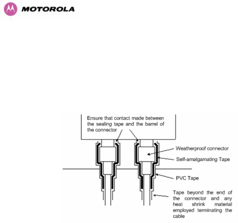
202
All joints should be weatherproofed using self-amalgamating tape. It is recommended that a
layer of PVC tape be placed over the self-amalgamating tape to protect the joint while the
self-amalgamating tape cures and gives additional protection. 1209HFigure 123 shows this
diagrammatically for the 600 Series bridge end of the antenna cables. If the antenna
manufacturer has not supplied guidance on this matter, the same technique should be
employed at the antenna end of the cable.
Figure 123 - Weatherproofing the Antenna Connections
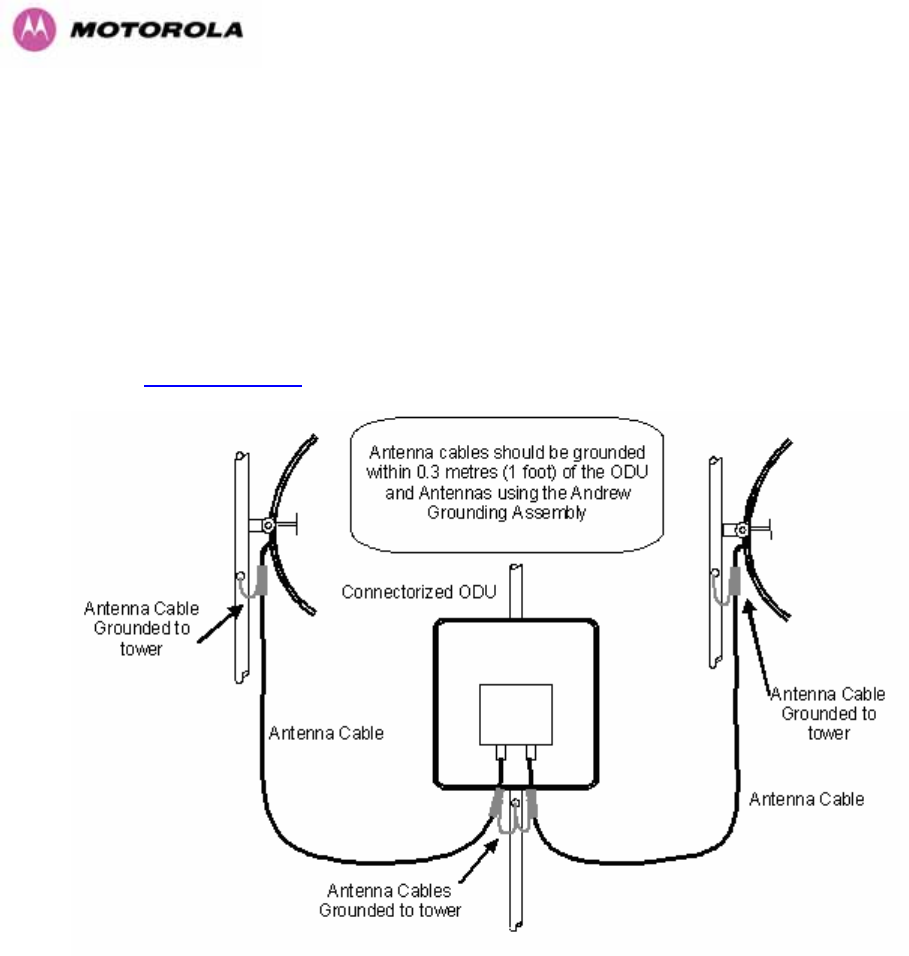
203
13.9 Additional Lightning Protection
The following guidelines should be applied in addition to those described in Section 1210H11
”1211HLightning Protection”.
13.9.1 ODU Mounted Outdoors
Where the ODU is mounted outdoors and is mounted some distance from the antenna, it is
advisable to add additional grounding by utilizing Andrew Assemblies (such as Andrew Type
223158 485Hwww.andrew.com) as shown in 1212HFigure 124.
Figure 124- Additional Grounding When Using Connectorized Units
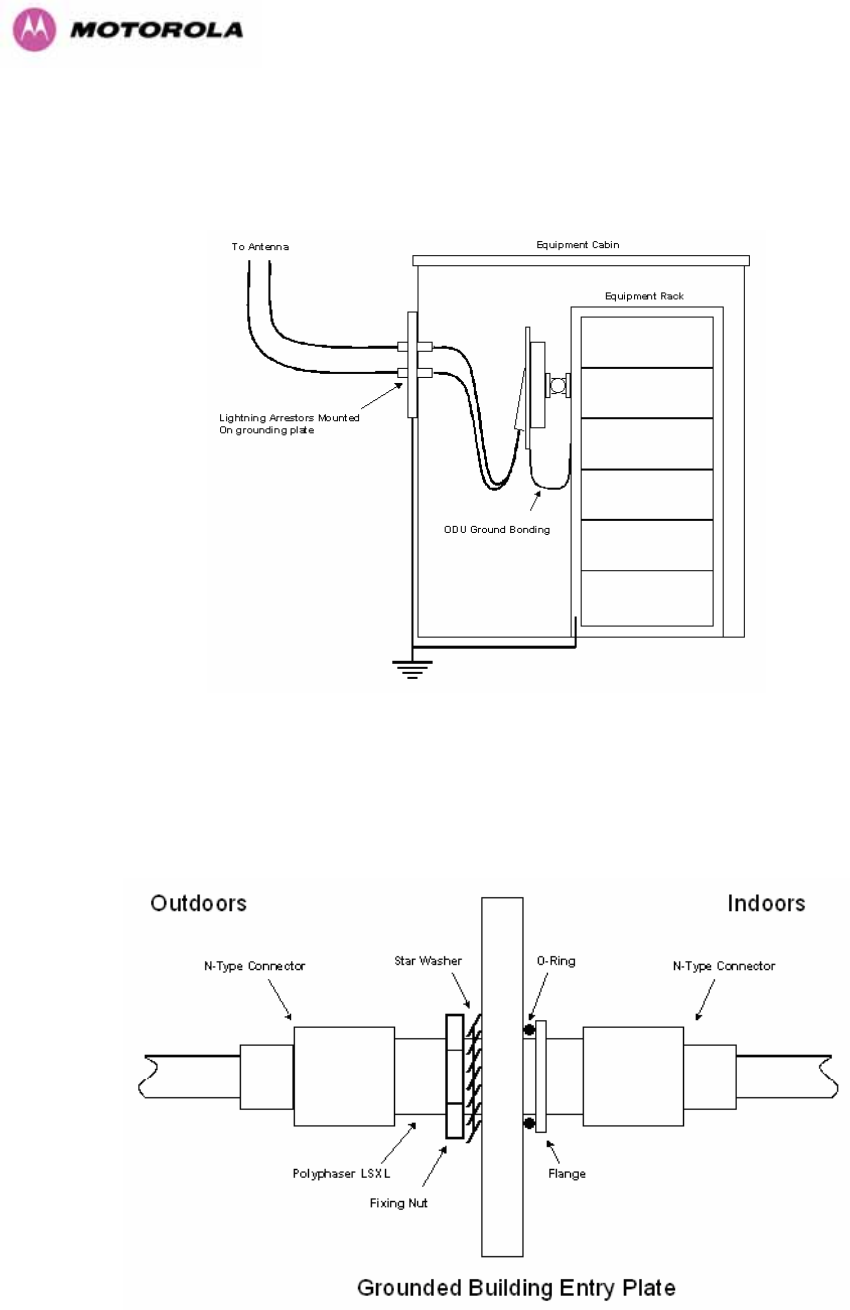
204
13.9.2 ODU Mounted Indoors
Where the ODU is mounted indoors, lightning arrestors should be deployed where the
antenna cables enter the building as shown in 1213HFigure 125.
Figure 125 - Lightning Arrestor Mounting
The lighting arrestors should be ground bonded to the building ground at the point of entry.
Motorola recommends Polyphaser LSXL-ME or LSXL lighting arrestors. These should be
assembled as show in Error! Reference source not found..
Figure 126 - Polyphaser Assembly

205
14 TDD Synchronization Configuration and Installation Guide
14.1 Introduction
This Section gives instructions for installing and configuring the TDD (Time Division Duplex)
Synchronization feature for Motorola PTP600 Series bridges. Using this feature, a single
frequency channel is assigned to both the transmitter and the receiver. This has many
advantages such as:
• Minimising interference between multiple links on a single mast.
• Improving frequency re-use
• Reducing spatial / angular separation between PTP links when installed on the same
mast
• Improving Link Budgets (when using higher Tx power)
This section includes also:
• Wiring Diagrams
• Step-by-Step configuration using web interface.
• Illustrations showing the placement of the GPS box and the recommended components
for installation

206
14.2 TDD Synchronization Installation and Wiring Guidelines
As mentioned in Section 1214H5.2.4, enabling the TDD Synchronization25F
26 feature is a two-stage
process:
1. Install GPS Synchronization unit
2. Use web interface to enable and configure parameters
14.2.1 Installing the Recommended GPS Synchronization Kit
The recommended GPS Sync installation kit includes the following:
• GPS Sync Box unit from MemoryLink (see 1215HFigure 127), with two attached
terminated Ethernet and Sync cables and cable glands (2) which connect directly
to a PTP 600 Series ODU, and an attached un-terminated Ethernet cable.
• Mounting bracket and mounting bracket screws
• Outdoor rated UV resistant cable tie
• GPS Sync Box User Manual.
In addition to the hardware mentioned above, it is recommended to have an appropriate
lightning protection (ALPU-ORT in Section 1216H16).
26 TDD Synchronization assumes that the user is familiar with network planning issues. For simple
networks, it is advisable not to use the “Expert Mode” and rely on the configuration wizard.
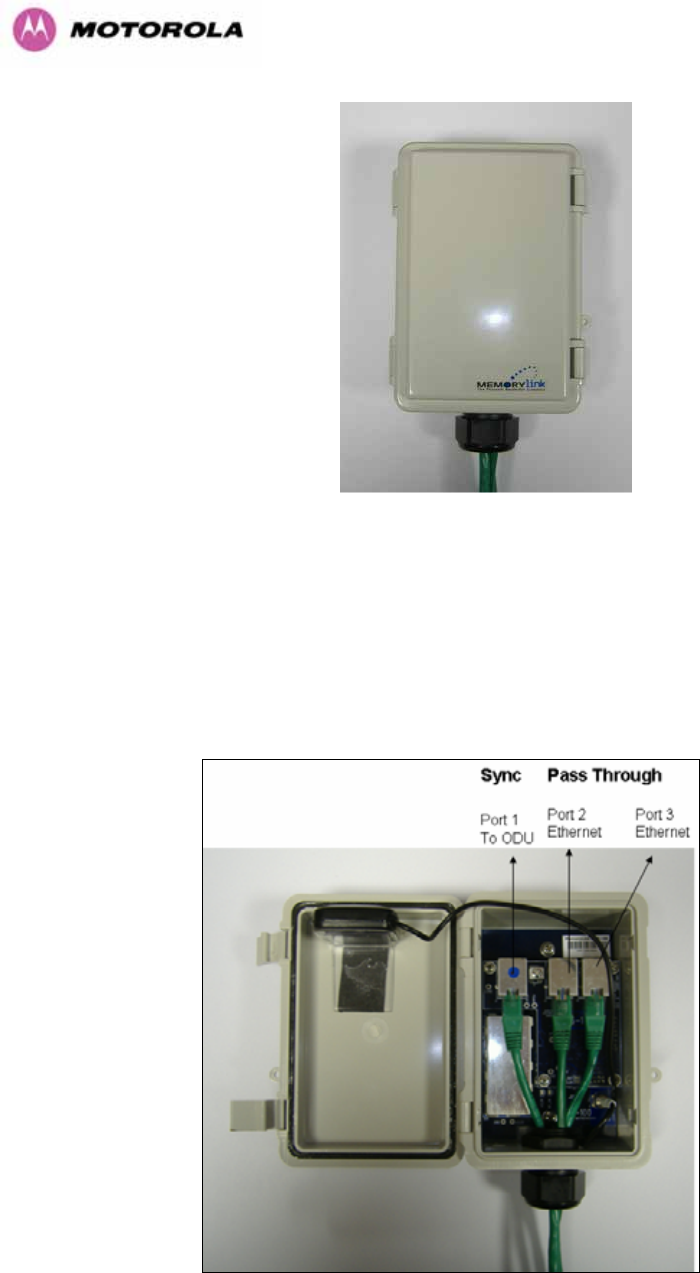
207
Figure 127 - GPS Synchronization Unit
NOTE: Refer to GPS Sync Box User manual for al the details on the lengths of all the cables
used to connect the GPS Sync Box to the ODU.
1217HFigure 128 shows the connections in the GPS Sync Box unit and 1218HFigure 129 is a diagram that
shows how to connect the GPS Sync box to the ODU and the Lightning protection unit.
Figure 128 - GPS Synchronization Unit Connections
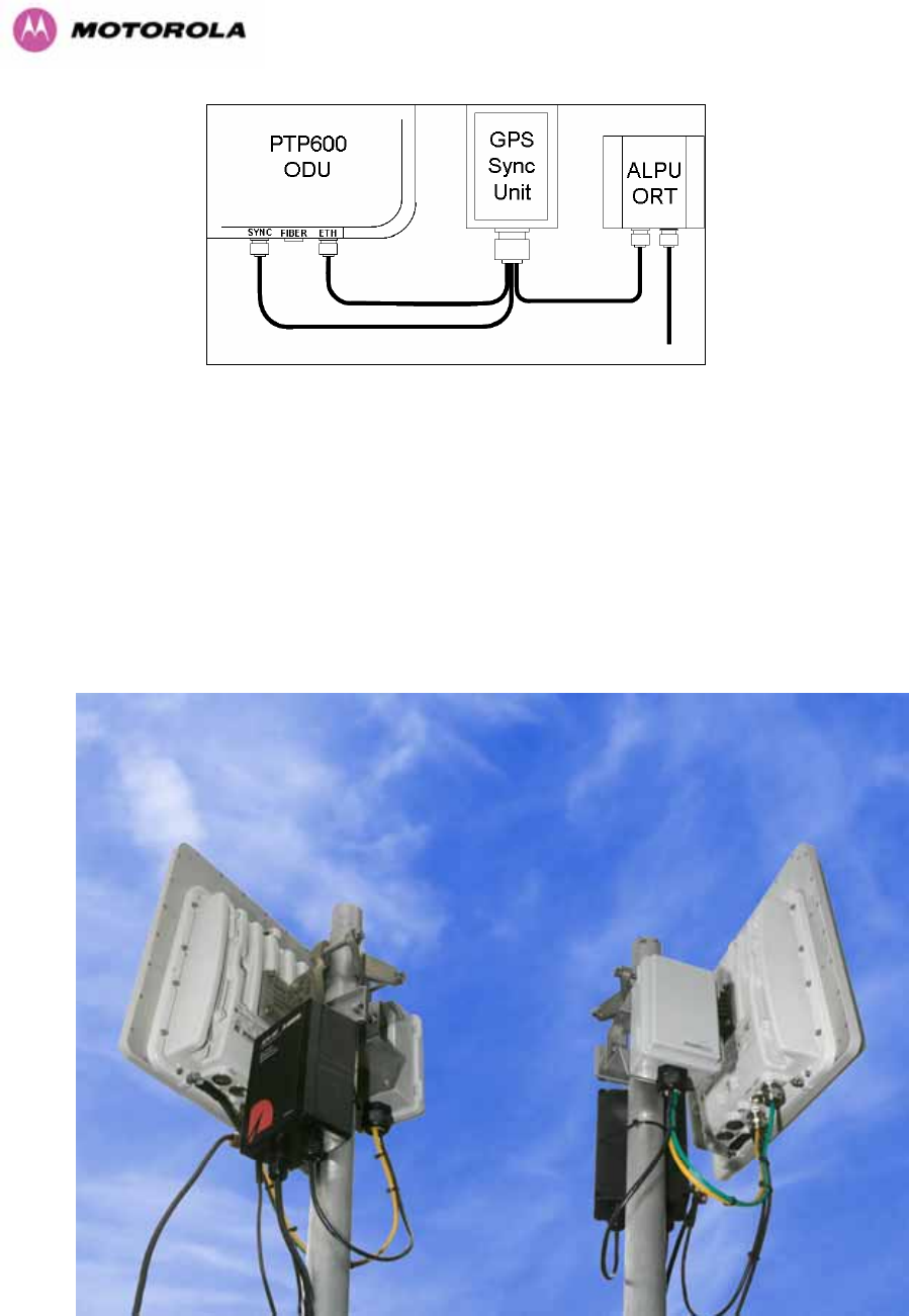
208
Figure 129 - TDD Sync - PTP600 Deployment Diagram
NOTE: Installation details of the GPS Sync Box are described in the GPS Sync Box User
Manual.
1219HFigure 130 shows an example of mast installation using lightning protection and a GPS Sync
Box unit.
Figure 130- GPS Synchronization Unit Complete Installation
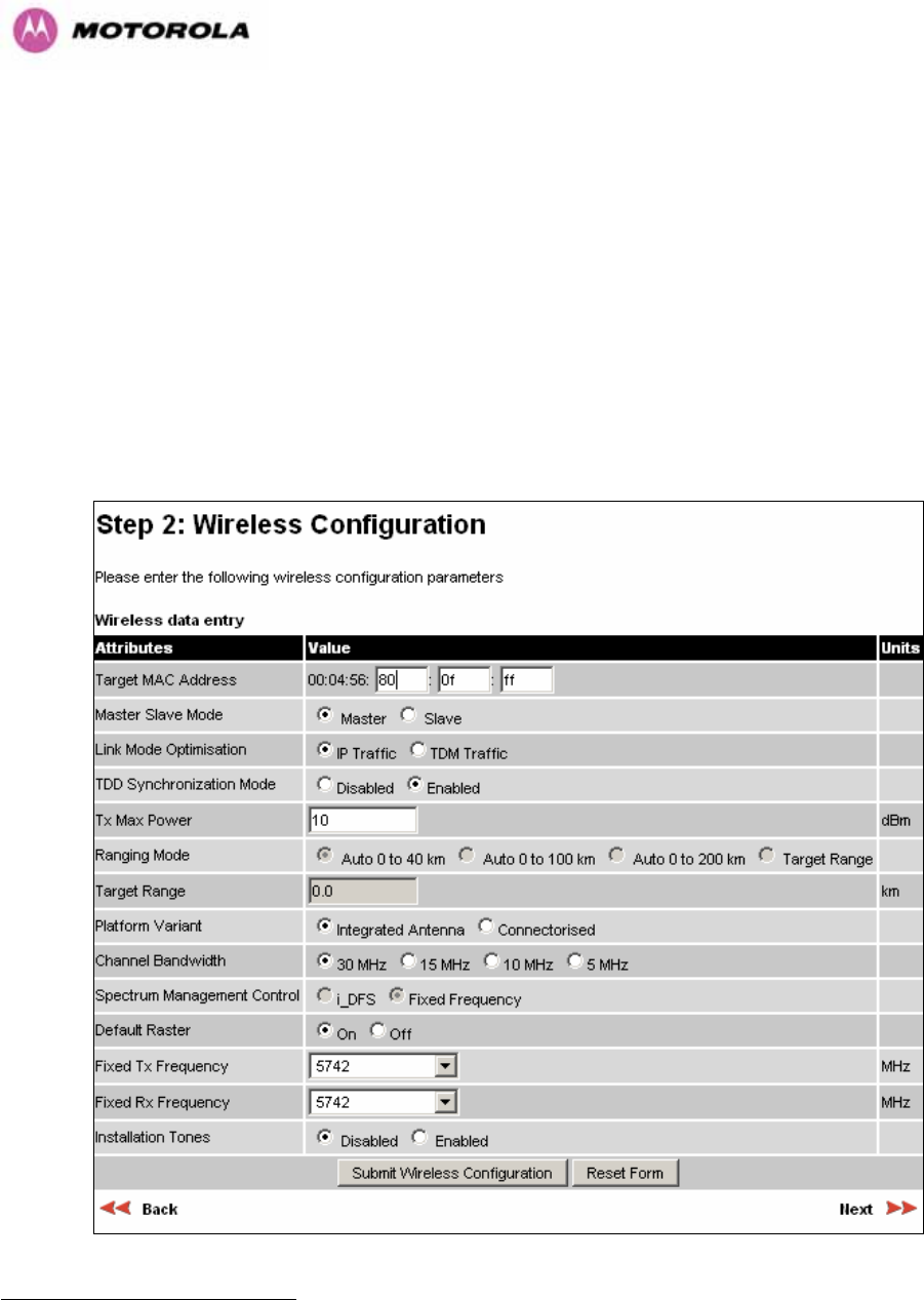
209
14.3 Configuring the TDD Synchronization Feature
TDD synchronization is enabled and configured using the install wizard during the installation
process of the link26F
27.
14.3.1 TDD Synchronization Enable
There are two synchronization modes (see 1220HFigure 131):
1. Disabled (Default): PTP600 operates exactly as for existing system releases (no
TDD Synchronization)
2. Enabled: PTP600 TDD Synchronization is enabled.
Figure 131 - Enabling TDD Synchronization Feature
27 TDD synchronisation is not available in regions where radar avoidance is enabled.
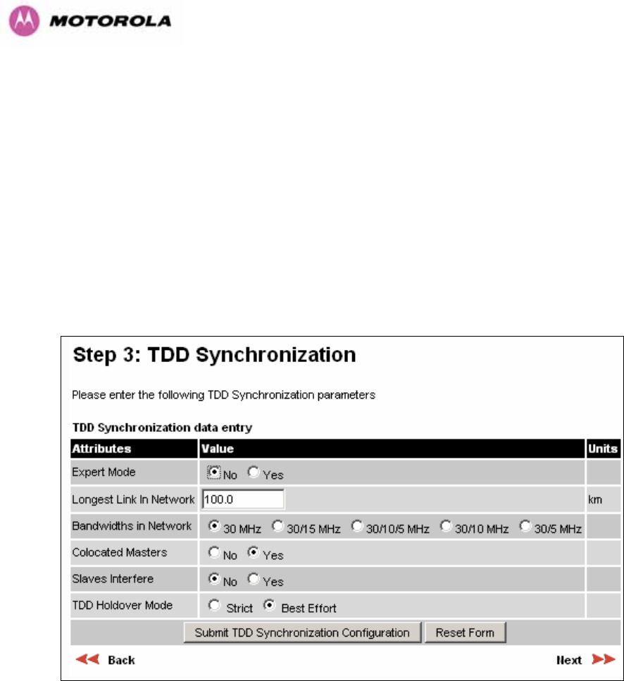
210
When TDD Synchronization is enabled, note the following changes to the existing controls in
the Installation wizard screens:
¾ ‘Ranging Mode’ and ‘Target Range’ controls are disabled on the wireless
configuration page.
¾ ‘Spectrum Management’ Control is forced to ‘Fixed Frequency’ operation only.
14.3.2 TDD Synchronization Configuration Menu
When TDD Synchronization is enabled, there is an extra installation screen (“TDD
Synchronization”) as shown in 1221HFigure 132.
Figure 132 - Configuring TDD Synchronization Feature – Screen 1
The TDD Synchronization screen provides the following controls:
Expert Mode: Select “Yes” to use “Expert Mode”. This is an option recommended only for
experienced network and cell planners to configure large and complex networks (see 1222HFigure
134 for parameters required to configure in this mode). See Section 1223H14.3.2.1 for detailed
description of the parameters to configure. If “Expert Mode” is not selected, then the user is
required to enter some basic information to allow the software to calculate the best values for
Frame Duration and Burst Duration.

211
Longest Link in Network: Default value is 100 kms (60 miles). It is the distance of the
longest link in the network (maximum is 200 kms or 120 miles).
Bandwidths in Network: It is very likely that there will be several different channel
bandwidths in a given network. 1224HTable 26 gives a list of bandwidth combinations that permit
synchronization without gross loss of efficiency. Note that depending on the channel
bandwidth size, only subsets of 1225HTable 26 will be shown in the configuration wizard screen.
Bandwidth
Combination
(MHz)
Available burst durations
(microseconds)
30 1451, 1088, 726
30/5
30/10
5/10/30 1088
15/30 1451, 726
15 2176, 1451, 726
10/15 2176
5/10 1088
10 2176, 1088
5 1088
Table 26 - Common Burst Durations

212
Colocated Masters: choose “Yes” to indicate that ODUs are colocated on the same mast. If
the option “No” is selected, then the control below is displayed (see 1226HFigure 133):
Master to Master Range: Maximum range is 200 Kms (120 miles).
Slave Interfere: Select “Yes” to indicate that a Slave ODU interferes. If the option “No” is
selected, then the control below is displayed (see 1227HFigure 133 ):
Slave to Slave Range: Maximum range is 200 Kms (120 miles).
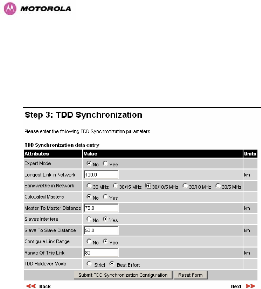
213
Configure Link Range: Choose “yes” to enter the range of the link in control below: Note
that Link Range MUST be less or equal to “Longest Link in Network”.
TDD Holdover Mode: Two values: “Strict” and “Best Effort”. If a PTP 600 master ODU is
configured for a TDD Holdover Mode set to “Strict”, then it will not transmit when
synchronization is lost. On the other hand, a link configured for TDD Holdover Mode set to
“Best Effort” will synchronize when a reference signal is available, but will otherwise use best
efforts to operate in unsynchronized fashion.
Figure 133 - Configuring TDD Synchronization Feature - Screen 2
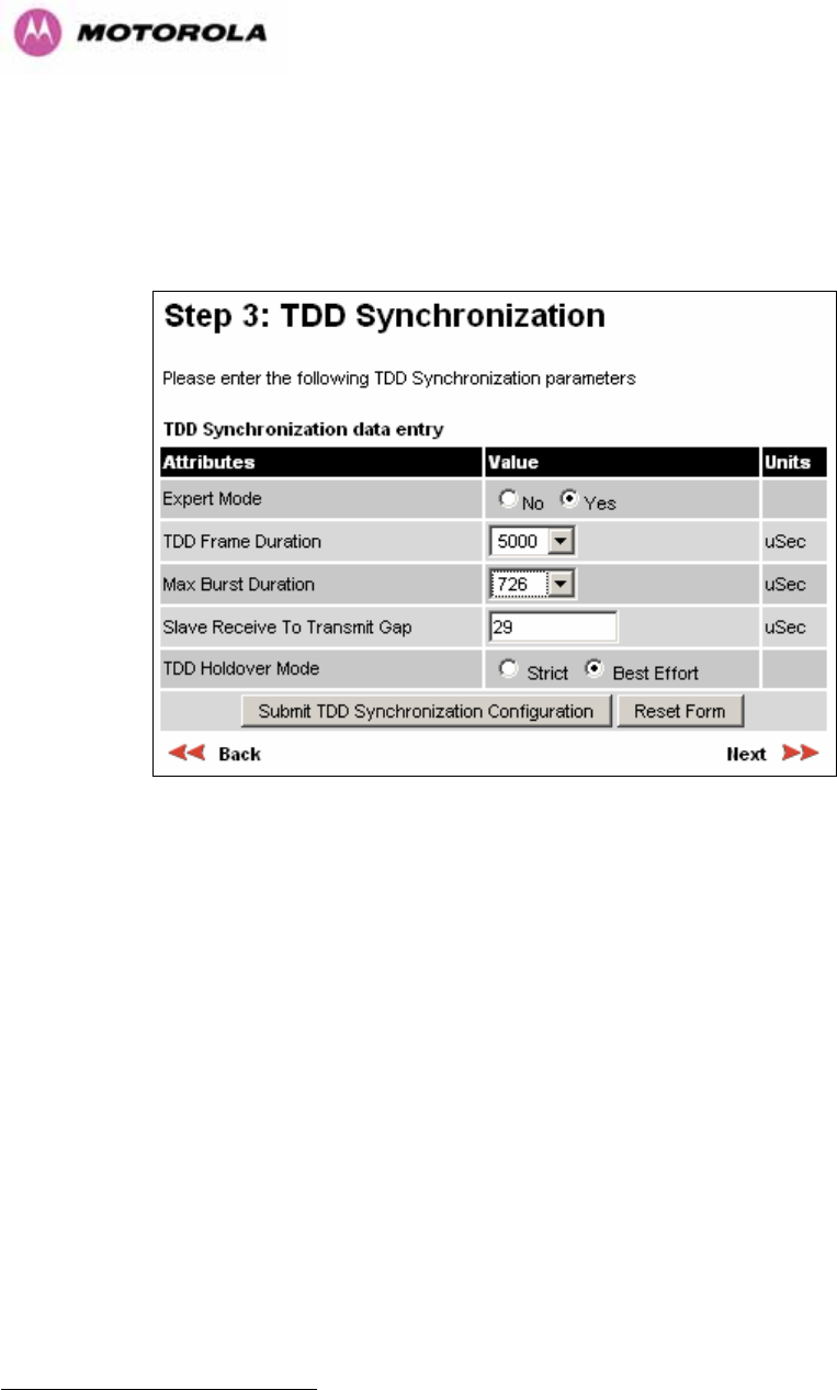
214
14.3.2.1 TDD Synchronization Configuration – Expert Mode
When “Expert Mode” is selected, the user is required to configure the parameters27F
28 shown in
1228HFigure 134.
Figure 134 - Configure TDD Synchronization Expert Mode
The configuration parameters are described below.
28 For the non-expert mode, the controls in Figure 134 are automatically filled by the software

215
TDD Frame Duration: the available frame rates are given in 1229HTable 27.
Indicated
Frame Duration
(microseconds)
Frame
Rate (Hz) TDD Frame
(clock periods)
1730 578 276816
1805 554 288808
1908 524 305344
2000 500 320000
2079 481 332640
2179 459 348584
2283 438 365296
2392 418 382776
2500 400 400000
2618 382 418848
2747 364 439560
2882 347 461096
3012 332 481928
3145 318 503144
3311 302 529802
3460 289 553634
3610 277 577618
3817 262 610688
4000 250 640000
4184 239 669456
4367 229 698690
4566 219 730594
4785 209 765550
5000 200 800000
5236 191 837696
5495 182 879120
5714 175 914286
6024 166 963856
6410 156 1025642
Table 27 - TDD Frame Duration

216
Maximum Burst Duration: When operated in TDD Synchronization mode, the PTP 600
ODU will support the combinations of channel bandwidth and OFDM size as listed in 1230HTable
28. Note that in IP Mode, select the largest supported value for the appropriate bandwidth
combination to maximize throughput. In TDM mode, select an appropriate value to achieve
the lowest latency consistent with the most robust modulation mode.
Bandwidth
(MHz) Symbols per
burst Burst Duration
(s) Burst Duration
(clock cycles)
15 10
30 20
725.33 116052
5 5
10 10
30 30
1088.00 174080
15 20
30 40
1450.66 232106
10 20
15 30
2176.00 348160
Table 28 - PTP 600 Burst Durations

217
NOTE: In TDM link optimization mode, burst duration should be selected so as to achieve the
lowest latency consistent with throughput sufficient to support the maximum allowed
configuration of internal TDM interfaces at the most robust modulation mode. 1231HTable 29 lists
the frame duration thresholds for TDM operation. Frame duration depends on burst duration.
Burst duration should be selected by testing each of the values available in the applicable
bandwidth combination, starting with the shortest burst duration, until the resulting frame
duration falls within the limits listed in 1232HTable 29.
Bandwidth Combination
(MHz)
Frame Duration
(microseconds) Burst Duration
(microseconds)
≤ 2079 µs 726 µs
> 2079 µs, ≤ 3145 µs 1088 µs
30
> 3145 µs 1451 µs
5/10/30 > 0 1088 µs
≤ 2079 µs 726 µs 15/30
> 2079 µs 1451 µs
≤ 2079 µs 726 µs
> 2079 µs 1451 µs
15
Not used 2176 µs
10/15 > 0 2176 µs
≤ 2747 µs 1088 µs 10
> 2747 µs 2176 µs
5 > 0 1088 µs
Table 29 - Burst Durations in TDM Link Optimization
Slave Receive to Transmit Gap: This is a calculated value (default is 29).
TDD Holdover Mode: Strict or Best Effort
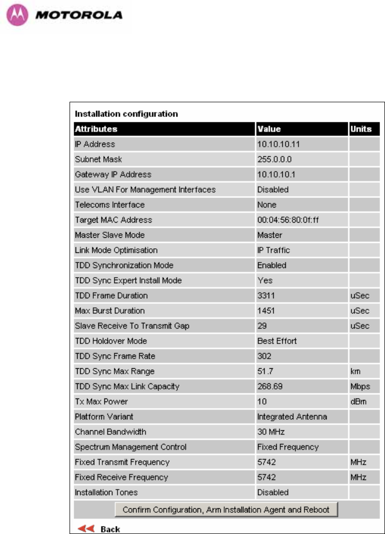
218
14.3.2.2 Confirm Settings and Reboot ODU
Figure 135 - Confirm TDD Synchronization Configuration Parameters
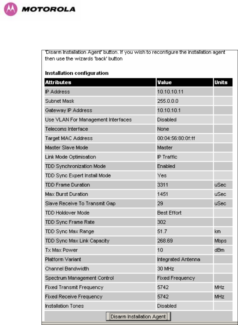
219
Figure 136 - Disarm Following TDD Synchronization
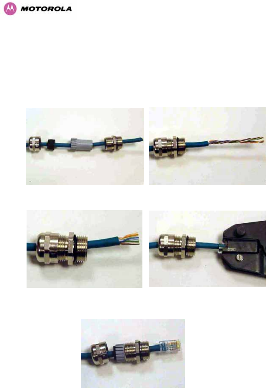
220
15 E1/T1 Installation Guide
15.1 Preparing the PTP 600 Series Bridge E1/T1 Cable
Note: The maximum cable length between the ODU and the customers terminating
equipment is 200m (656 feet) for T1.
The E1/T1 cable should be assembled to the following instructions:
Step 1: Assemble gland on cable as shown Step 2: Strip the outer insulation
Step 3: Arrange conductors as shown in fig.
A2 and cut to length
Step 4: Insert conductors and crimp
Figure 137 - Completed ODU Connector
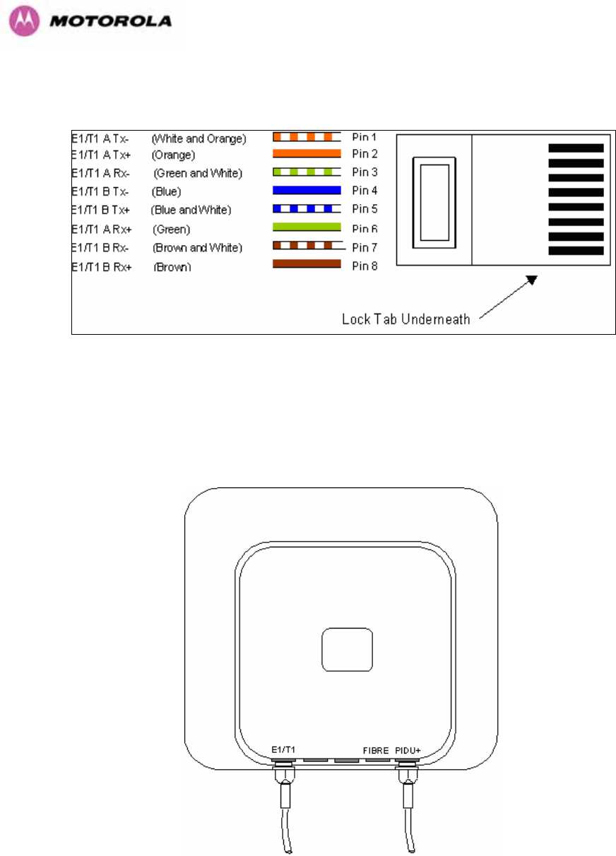
221
This procedure applies to the ODU termination. The above procedure should be repeated for
the customer equipment end of the cable when the cable is terminated with a RJ45.
Figure 138 - RJ45 Pin Connection (T568B Color Coding)
15.2 Making the Connection at the ODU
Looking at the back of the unit with the cable entry at the bottom, the PTP 600 Series Bridge
E1/T1 connection is the first hole on the left (1233HFigure 139) and is labeled E1/T1.
Figure 139 - PIDU Plus and E1-T1 Connection
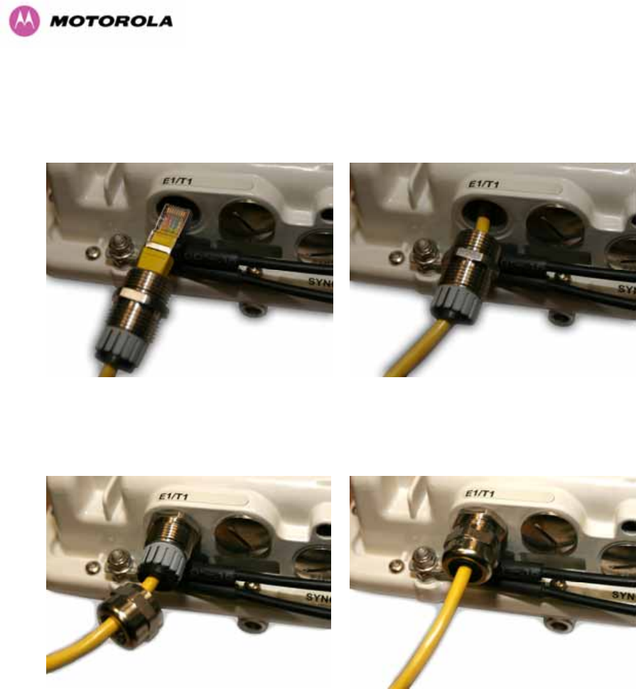
222
The following procedure describes how connection is made at the ODU. It is often easier to
carry out this procedure on the ground or a suitable surface prior to mounting the ODU.
Ensure no power is connected to the PIDU Plus.
Step 1: Assemble the cable as described in
above
Step 2: Insert the RJ45 connector making sure
that the locking tab snaps home
Step 3: Screw in the body of the weather
proofing gland and tighten
Step 4: Screw on the clamping nut and tighten

223
Should it be necessary to disconnect the
E1/T1 cable at the ODU this can be
achieved by removing the weatherproofing
gland and depressing the RJ45 locking tab
with a small screwdriver as shown in the
opposite photograph.
Figure 140 - Disconnecting the ODU

224
15.3 Routing the Cable
After connecting the cable to the ODU it can be routed and secured using standard cable
routing and securing techniques. When the cable is in place it can then be cut to the desired
length.
15.4 Fitting a Surge Arrestor
If you have opted to fit a Surge Arrestor, it should be installed as described in Section A1.5
“Lightning Protection”
15.5 Customer Cable Termination
The two channels can be separated by means of a patch panel which may include Baluns for
transmission over 75 Ohm co-axial unbalanced lines. Such equipment should conform to the
requirements of C.C.I.T.T. G703. An example of a Balun is shown below. It allows the
transmit and receive data carried over a 75 Ohm cable to be converted to a balanced form for
transmission over a 120 Ohm signal balanced twisted pair.
Figure 141 - Example of a Balun
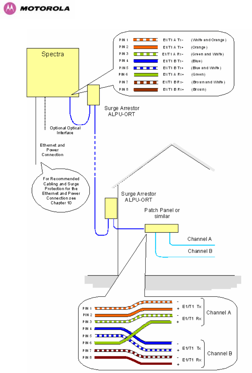
225
Figure 142 - Diagrammatically Showing the E1-T1 Connections
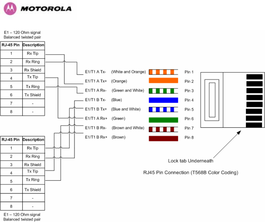
226
Figure 143 - Two E1-T1-120 Ohms signal Balanced to PTP600 Interface

227
16 Lightning Protection
16.1 Overview
Section 1234H11 in the main body of this manual contains the requirements for the Motorola PTP
600 Series deployment. This section details the additional requirements for the deployment of
E1/T1.
16.2 Recommended Additional Components for E1/T1 Installation.
The recommended components below are in addition to those listed in Section 1235H11, the extra
components required for the E1/T1 installation are:
• Screened Cat 5 Cable
• Surge Arrestor Units — Transtector type ALPU-ORT, 4 required per link.
(486Hwww.transtector.com)
• RJ45 screened connectors
• 8 AWG Grounding Cable
For a description of Zone A and Zone B refer to Section 1236H11.
Zone A Zone B
Earth ODU Mandatory Mandatory
Screen Cable Mandatory Mandatory
Surge Arrestor Unit ALPU-ORT at ODU Mandatory Mandatory
Earth Cable at Building Entry Mandatory Mandatory
Surge Arrestor Unit ALPU-ORT at Building Entry Mandatory Mandatory
Table 30 - Protection Requirements
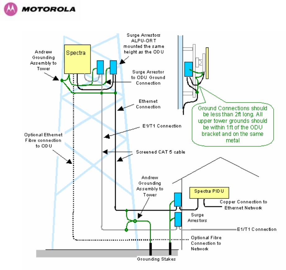
228
Figure 144 - Typical Mast Installation with the addition of the E1-T1 cable
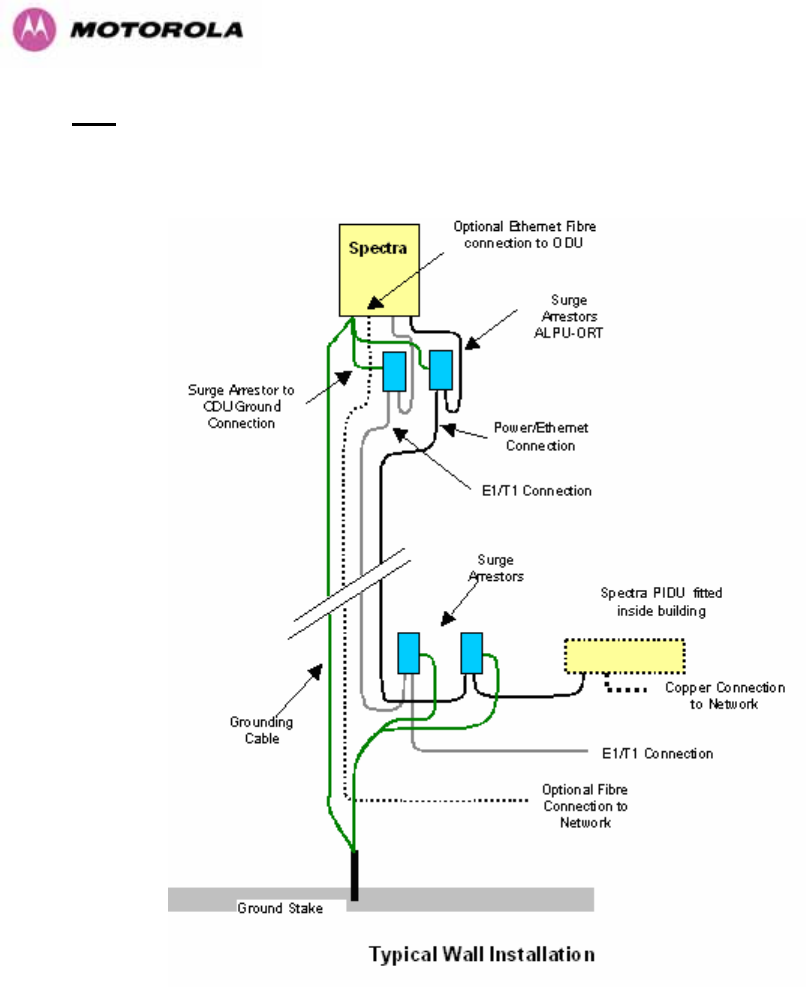
229
Note: There may be a local regulatory requirement to cross bond the CAT 5 drop cable at
regular intervals to the mast. This may be as frequent as every 10 meters (33 feet).
Figure 145 - Wall Installation with the addition of E1-T1 cable

230
16.3 Surge Arrestor Wiring
An Andrew Grounding Kit and Surge Arrestor Unit must be located at the ODU and reliably
grounded as shown in 1237HFigure 111. There may also be a regulatory requirement to crossbond
the screened CAT-5 at regular intervals up the mast. Refer to local regulatory requirements
for further details.
A second Surge Arrestor Unit should be mounted at the building entry point and must be
grounded.
The termination of the CAT-5 Cable into the Surge Arrestor Unit is illustrated in 1238HTable 31,
1239HTable 32 and 1240HFigure 146. The screen from the cable must be terminated into the ground
terminal within the unit to ensure the continuity of the screen. Earth Sleeving should be used
to cover the shield ground connection to prevent internal shorting within the unit.
Terminal Identification Conductor RJ45 Pin
CON3 Pin 1 Orange/White 1
CON3 Pin 2 Orange 2
CON3 Pin 3 Green/White 3
CON3 Pin 6 Green 6
CON1 Pin 4 Blue 4
CON1 Pin 5 Blue/White 5
CON1 Pin 7 Brown/White 7
CON1 Pin 8 Brown 8
Table 31 - Surge Arrestor ALPU-ORT Cable 1 Termination
Terminal Identification Conductor RJ45 Pin
CON4 Pin 1 Orange/White 1
CON4 Pin 2 Orange 2
CON4 Pin 3 Green/White 3
CON4 Pin 6 Green 6
CON2 Pin 4 Blue 4
CON2 Pin 5 Blue/White 5
CON2 Pin 7 Brown/White 7
CON2 Pin 8 Brown 8
Table 32 - Surge Arrestor ALPU-ORT Cable 2 Termination
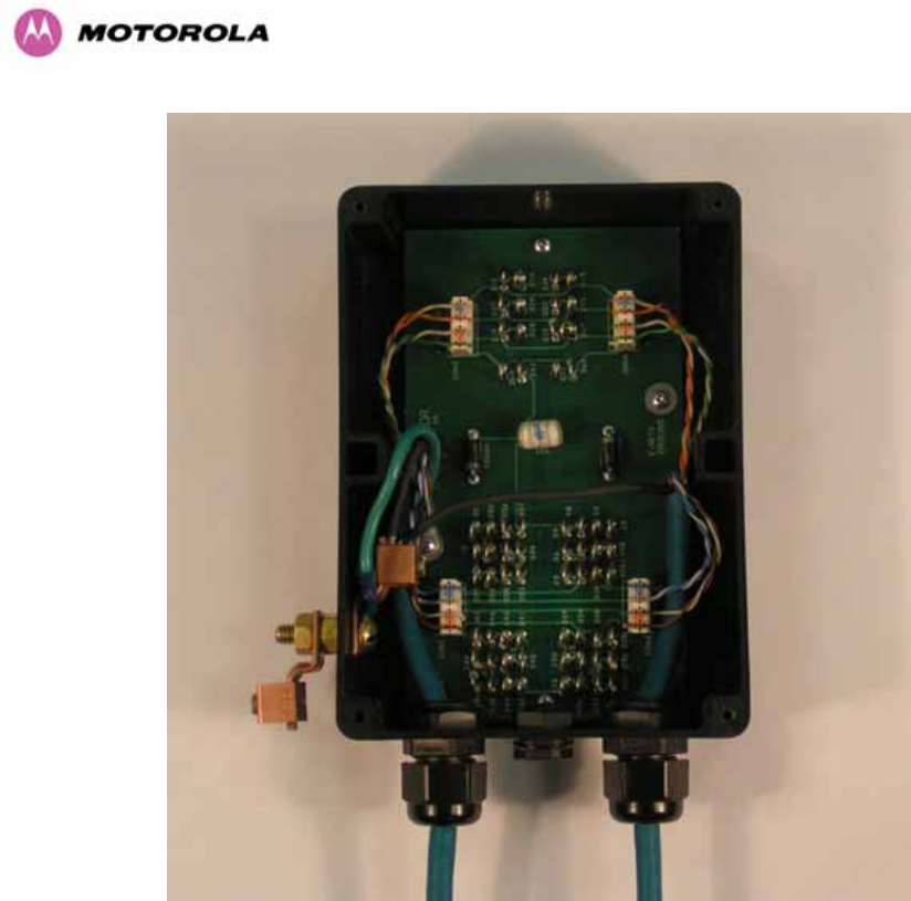
231
Figure 146 - Surge Arrestor ALPU-ORT Connection Illustration
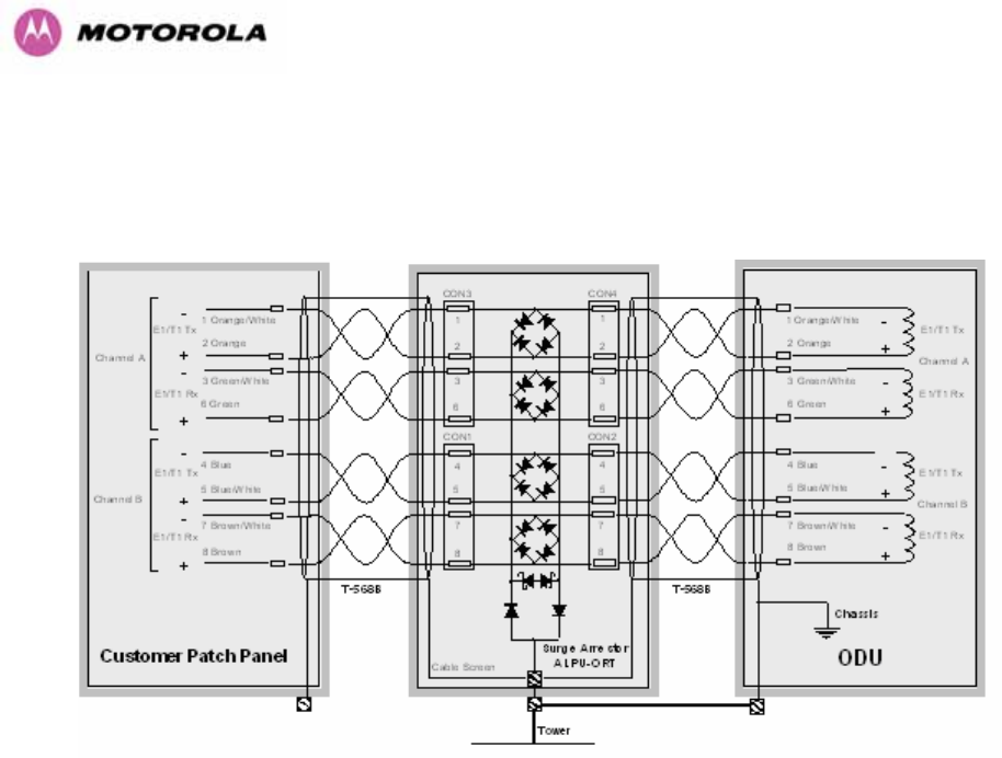
232
16.4 Testing Your Installation
If you have followed the above instructions you will have wired your systems to the following
diagram:
Figure 147 - Simplified Circuit Diagram (Only One Transtector Shown For Clarity)
16.4.1 Pre-Power Testing
Before connecting your E1/T1 source, check the following resistances:
1. Check the cable resistance between pins 3 & 6 (Green/White & Green) and 7 & 8
(Brown/White & Brown). Check against 1241HTable 33 column 2.
2. Check the cable resistance between pins 1 & 2 (Orange/White & Orange) and 4 & 5
(Blue & Blue/White). Check against 1242HTable 33 column 3.

233
CAT-5 Length (Meters) Resistance between pins
3 & 6 and pins 7 & 8
(ohms)
Resistance between pins
1 & 2 and pins 4 & 5
(ohms)
0 0.8 1.3
10 2.5 3.0
20 4.2 4.7
30 5.9 6.4
40 7.6 8.2
50 9.3 9.8
60 11.0 11.5
70 12.7 13.2
80 14.4 14.9
90 16.1 18.2
100 17.8 18.3
Table 33 - Resistance Table Referenced To the E1/T1 Source
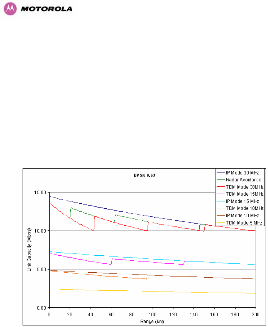
234
17 Data Rate Calculations
To aid the calculation of data rate throughput, the following plots of throughput verses link
range have been produced for all the PTP 600 Series modulation modes, assuming the units
are connected using Gigabit Ethernet.
Aggregate data rate capacity can be calculated using four key system parameters:
• Receive modulation mode
• Transmit modulation mode
• Range Between the two wireless units
• Wireless link mode (IP or TDM)
Using these parameters the Receive and Transmit data rates can be looked up using the
plots 1243HFigure 148 through 1244HFigure 160.
Figure 148 - BPSK 0.63 Single Payload
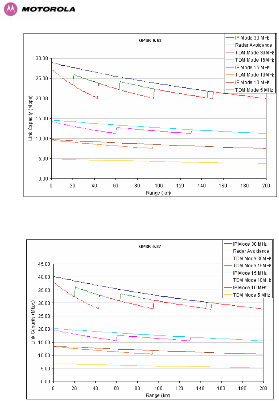
235
Figure 149 - QPSK 0.63 Single Payload
Figure 150 - QPSK 0.87 Single Payload
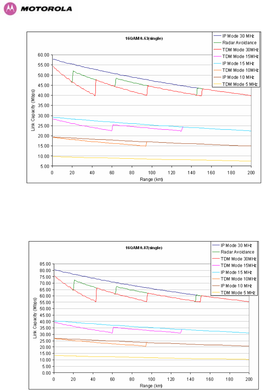
236
Figure 151 - 16 QAM 0.63 Single Payload
Figure 152 - 16 QAM 0.87 Single Payload
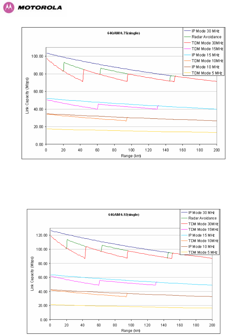
237
Figure 153 - 64 QAM 0.75 Single Payload
Figure 154 - 64 QAM 0.92 Single Payload
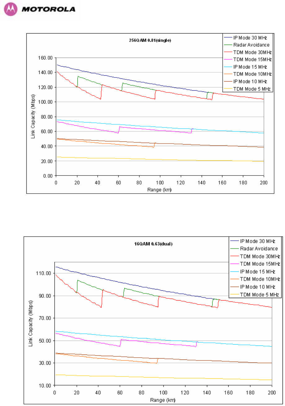
238
Figure 155 - 256 QAM 0.81 Single Payload
Figure 156 - 16 QAM 0.63 Dual Payload
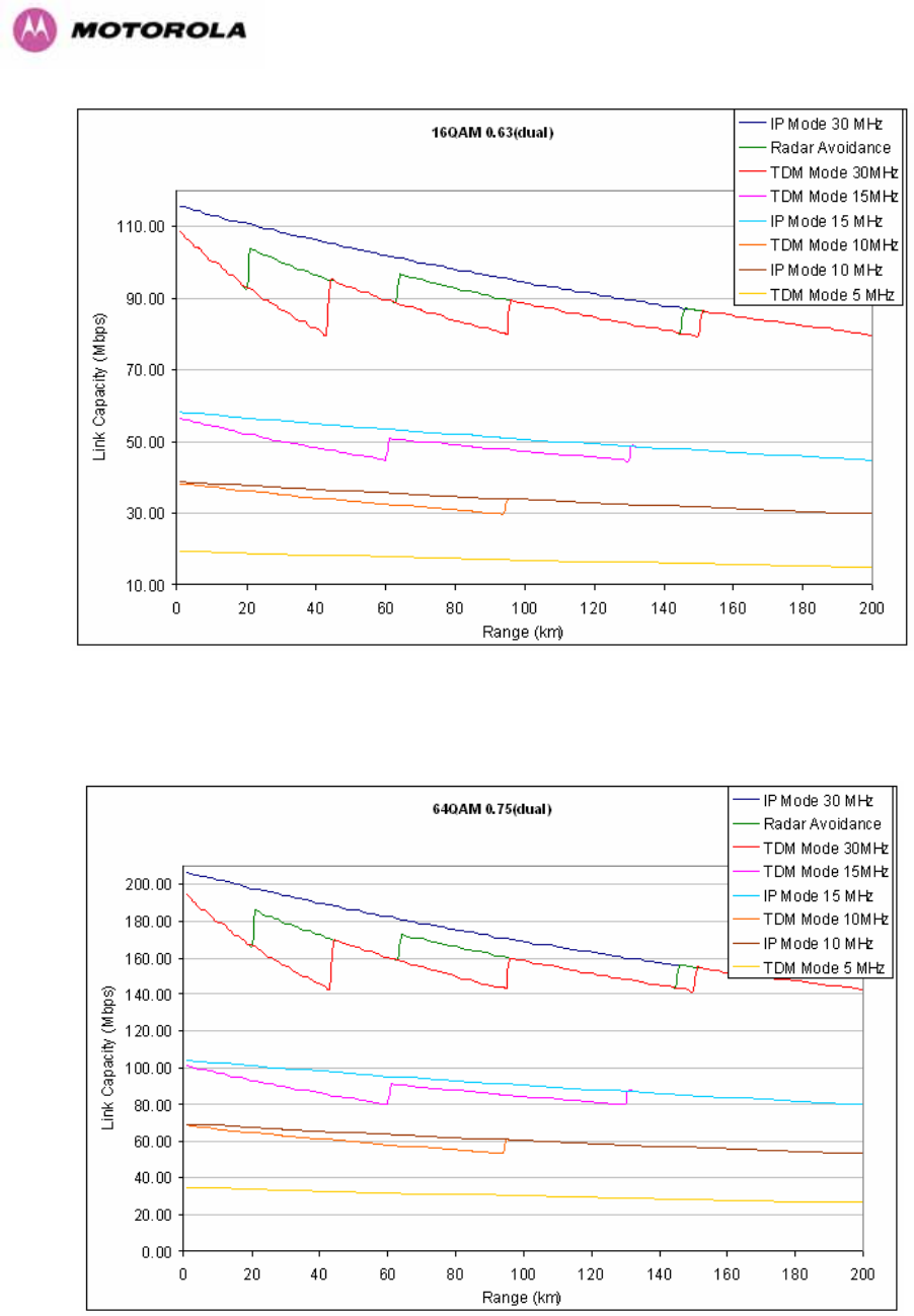
239
Figure 157 - 16 QAM 0.87 Dual Payload
Figure 158 - 64 QAM 0.75 Dual Payload
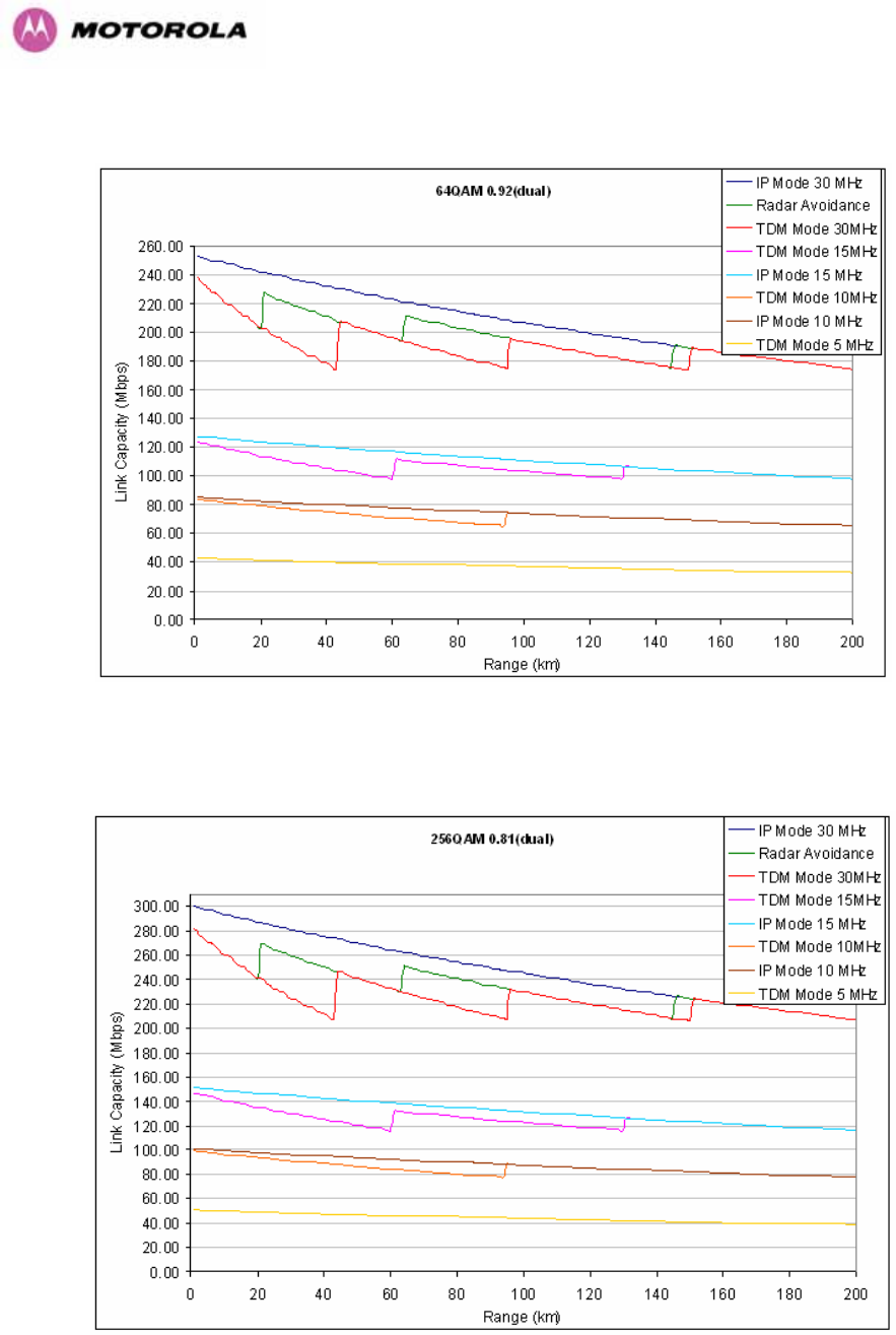
240
Figure 159 - 64 QAM 0.92 Dual Payload
Figure 160 - 256 QAM 0.81 Dual Payload

241
18 AES Encryption Upgrade
The Motorola PTP 600 Series bridges support link encryption using the NIST approved
Advanced Encryption Standard, H487HFIPS-197UTH. This standard specifies AES (Rijndael) as a
FIPS-approved symmetric encryption algorithm that may be used by U.S. Government
organizations (and others) to protect sensitive information.
Link Encryption is not available in the standard PTP 600 Series system. A license key to
enable link encryption can be purchased from your Motorola Point-to-Point Distributor or
Solutions Provider. AES can be activated on receipt of the activation on the 488HMotorola
Systems Support Page.
There are two levels of encryption that are available to purchase:
• 128-bit
• 128 and 256-bit
Option 1 allows the user to encrypt all traffic sent over the wireless link using 128-bit
encryption. Option 2 allows the user to encrypt traffic using either 128 or 256-bit encryption.
The configuration process for both encryption variants is identical except for the selection of
algorithm. The following configuration example is for a 256-bit encryption key.
18.1 Configuring Link Encryption
After purchasing AES encryption for the PTP 600 Series wireless link, two new license keys
will be issued, one for each end of the wireless link. The following configuration process gives
a step by step guide to enabling AES link encryption on a PTP 600 Series bridge.
18.2 Configuring Link Encryption
After purchasing AES encryption for the PTP 600 Series wireless link, two new license keys
will be issued, one for each end of the wireless link. The following configuration process gives
a step by step guide to enabling AES link encryption on a PTP 600 Series bridge.
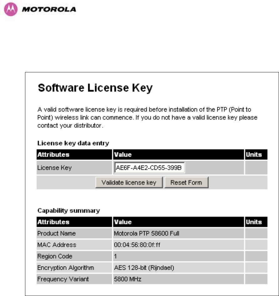
242
18.2.1 License Keys
The first step when configuring link encryption is to enter the new license keys in both 600
Series wireless units.
Figure 161 – AES Software License Key Data Entry
1245HFigure 161 shows the license key data entry screen. This screen can only be accessed by the
system administrator. If you do not have access to the PTP 600 Series system administration
pages then please contact your designated system administrator.
It must be noted that configuring link encryption will necessitate a 600 Series bridge service
outage. Therefore it is recommended that the configuration process be scheduled during an
appropriate period of low link utilization. Motorola recommends the following process for
entering new license keys and minimizing service outage.
1. Open two browsers, one for each end of the link
2. Navigate to the ‘License Key’ data entry page for each end of the link
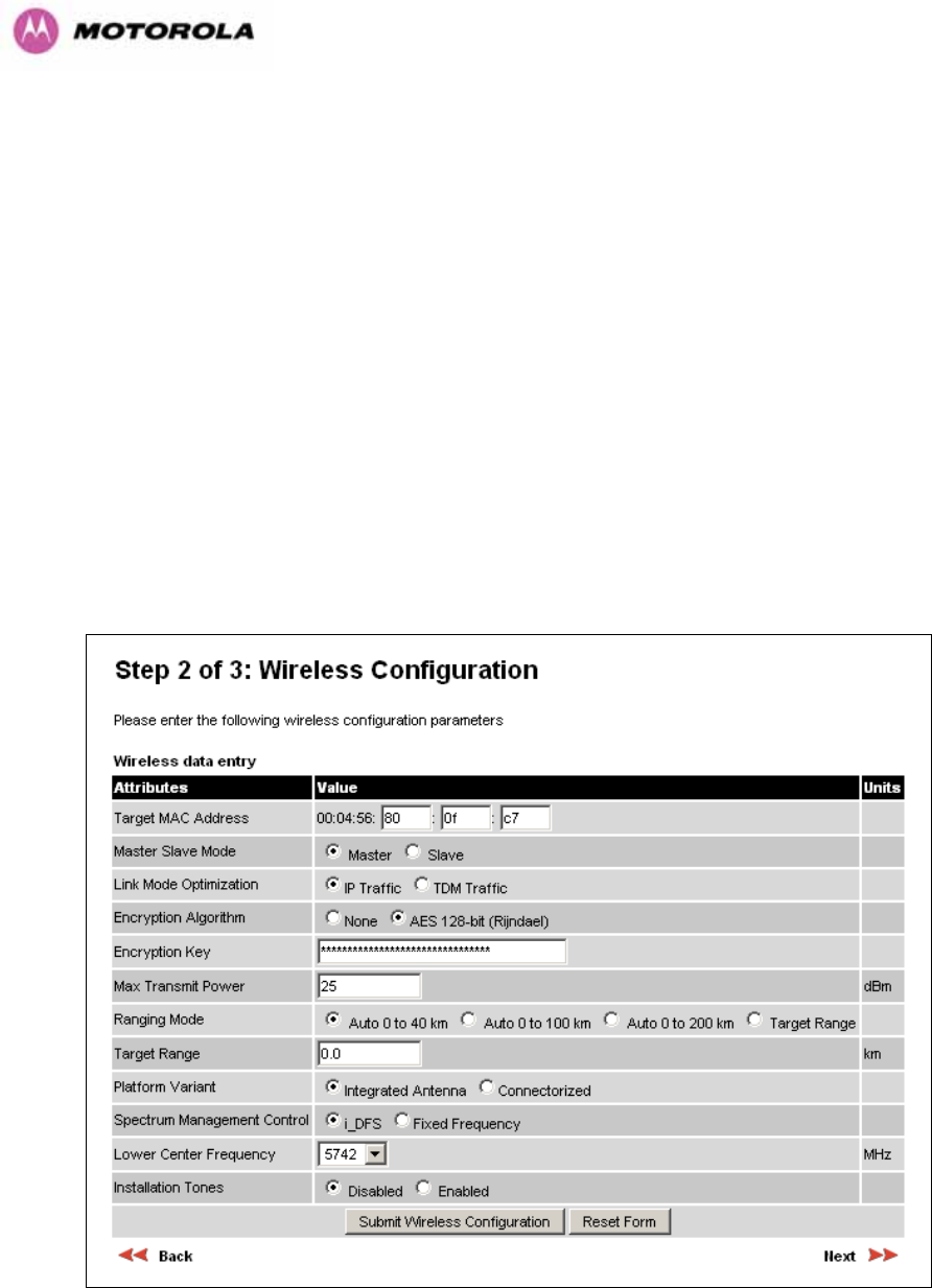
243
3. Enter the license keys and click the ‘Validate license key’ button at each end of the link.
This will allow the software to validate the license key prior to the system reset. (DO NOT
CLICK ARE YOU SURE POPUP DIALOG)
4. When both license keys have been successfully validated confirm the reboot for both
ends of the link. The software is designed to allow five seconds so that a user can
command both ends of the link to reset before the wireless link drops.
5. The link will automatically re-establish.
18.2.2 Encryption Mode and Key
Entering the license keys only does not initialize AES link encryption. Link encryption can only
be enabled via the Configuration or Installation Wizard pages. Motorola recommends that the
Configuration page 1246HFigure 162 be used to configure AES link encryption.
Figure 162 – AES Configuration Data Entry Page
244
Motorola recommends the following process for entering AES link encryption configuration:-
1. Open two browsers, one for each end of the link
2. Navigate to the ‘Configuration’ data entry page for each end of the link
3. At both ends of the link select the ‘AES (Rijndael)’ Encryption Algorithm required.
4. At both ends of the link enter ether an 128-bit or 256-bit encryption key. Note the key
consists of 32/64 case insensitive hexadecimal characters. The same Key must be
entered at both ends of the link. Failure to enter the same key will cause the link to fail.
5. Submit configuration on both ends of the link, but do not reboot.
6. Reboot both ends of the link 1247HFigure 163. The software is designed to allow five seconds
so that a user can command both ends of the link to reboot before the wireless link drops.
Figure 163 - Configuration Reboot Screen

245
18.3 Wireless Link Encryption FAQ
18.3.1 Encryption data entry fields are not available
Check that the correct license key has been inserted into the unit. The current license key is
displayed on the ‘License Key’ data entry page.
18.3.2 Link fails to bridge packets after enabling link encryption
If the wireless link status on the status web page indicates that the link is ‘Searching’, and you
can browse to the local end of the link but not to the remote end, then check that the same
encryption algorithm and key have been entered at both ends of the link. Failure to enter the
same algorithm and key will result in received packets not being decrypted correctly.
18.3.3 Loss of AES following downgrade
When downgrading (using Recovery software image 05-01 onwards) to an earlier version of
software that does not support AES, the unit will indicate that the region code is invalid. The
user will be required to re-install correct software (supplied when AES key was activated) and
reboot the unit.

246
19 Legal and Regulatory Notices
19.1 Important Note on Modifications
Intentional or unintentional changes or modifications to the equipment must not be made
unless under the express consent of the party responsible for compliance. Any such
modifications could void the user’s authority to operate the equipment and will void the
manufacturer’s warranty.
19.2 National and Regional Regulatory Notices – 5.8 GHz variant
19.2.1 U.S. Federal Communication Commission (FCC) and Industry Canada (IC) Notification
This system has achieved Type Approval in various countries around the world. This means
that the system has been tested against various local technical regulations and found to
comply. The frequency band in which the system operates is ‘unlicensed’ and the system is
allowed to be used provided it does not cause interference. Further, it is not guaranteed
protection against interference from other products and installations.
This device complies with part 15 of the US FCC Rules and Regulations and with RSS-210 of
Industry Canada. Operation is subject to the following two conditions: (1) This device may
not cause harmful interference, and (2) This device must accept any interference received,
including interference that may cause undesired operation. In Canada, users should be
cautioned to take note that high power radars are allocated as primary users (meaning they
have priority) of 5250 – 5350 MHz and 5650 – 5850 MHz and these radars could cause
interference and/or damage to license-exempt local area networks (LELAN).
This equipment has been tested and found to comply with the limits for a Class B digital
device, pursuant to Part 15 of the US FCC Rules and with RSS-210 of Industry Canada.
These limits are designed to provide reasonable protection against harmful interference in a
residential installation. This equipment generates, uses, and can radiate radio-frequency
energy and, if not installed and used in accordance with these instructions, may cause
harmful interference to radio communications. If this equipment does cause harmful
interference to radio or television reception, which can be determined by turning the
equipment on and off, the user is encouraged to correct the interference by one or more of
the following measures:
• Increase the separation between the affected equipment and the unit;
• Connect the affected equipment to a power outlet on a different circuit from that which the
receiver is connected to;
• Consult the dealer and/or experienced radio/TV technician for help.
• FCC IDs and Industry Canada Certification Numbers are listed in 1248HTable 34

247
Table 34 - US FCC IDs and Industry Canada certification numbers
Where necessary, the end user is responsible for obtaining any National licenses required to
operate this product and these must be obtained before using the product in any particular
country. Contact the appropriate national administrations for details on the conditions of use
for the bands in question and any exceptions that might apply. Also see 489Hwww.ero.dk for
further information.
19.2.2 European Union Notification
The 5.8 GHz connectorized product is a two-way radio transceiver suitable for use in
Broadband Wireless Access System (WAS), Radio Local Area Network (RLAN), or Fixed
Wireless Access (FWA) systems. It is a Class 2 device and uses operating frequencies that
are not harmonized throughout the EU member states. The operator is responsible for
obtaining any national licenses required to operate this product and these must be obtained
before using the product in any particular country.
This equipment complies with the essential requirements for the EU R&TTE Directive 1999/5/EC.
The use of 5.8GHz for Point to Point radio links is not harmonized across the EU and currently the
product may only be deployed in the UK and Eire (IRL). However, the regulatory situation in Europe is
changing and the radio spectrum may become available in other countries in the near future.
This equipment is marked
to show compliance with the European R&TTE directive 1999/5/EC.

248
The relevant Declaration of Conformity can be found at 490Hwww.motorola.com/ptp
European Union (EU) Waste of Electrical and Electronic Equipment (WEEE) directive
The European Union's WEEE directive requires that products sold into EU countries must
have the crossed out trash bin label on the product (or the package in some cases).
As defined by the WEEE directive, this cross-out trash bin label means that customers and
end-users in EU countries should not dispose of electronic and electrical equipment or
accessories in household waste. Customers or end-users in EU countries should contact their
local equipment supplier representative or service center for information about the waste
collection system in their country.
19.2.3 UK Notification
The 5.8 GHz connectorized product has been notified for operation in the UK, and when
operated in accordance with instructions for use it is compliant with UK Interface Requirement
IR2007. For UK use, installations must conform to the requirements of IR2007 in terms of
EIRP spectral density against elevation profile above the local horizon in order to protect
Fixed Satellite Services. The frequency range 5795-5815 MHz is assigned to Road Transport
& Traffic Telematics (RTTT) in the U.K. and shall not be used by FWA systems in order to
protect RTTT devices. UK Interface Requirement IR2007 specifies that radiolocation services
shall be protected by a Dynamic Frequency Selection (DFS) mechanism to prevent co-
channel operation in the presence of radar signals.
Important Note
This equipment operates as a secondary application, so it has no rights against harmful
interference, even if generated by similar equipment, and cannot cause harmful interference
on systems operating as primary applications.

249
19.3 National and Regional Regulatory Notices – 5.4 GHz Variant
19.3.1 U.S. Federal Communication Commission (FCC) and Industry Canada (IC) Notification28F
29
This device complies with part 15.407 of the US FCC Rules and Regulations and with RSS-
210 Issue 7 of Industry Canada. Operation is subject to the following two conditions: (1) This
device may not cause harmful interference, and (2) This device must accept any interference
received, including interference that may cause undesired operation. In Canada, users should
be cautioned to take note that high power radars are allocated as primary users (meaning
they have priority) of 5250 – 5350 MHz and 5650 – 5850 MHz and these radars could cause
interference and/or damage to license-exempt local area networks (LELAN).
This equipment has been tested and found to comply with the limits for a Class B digital
device, pursuant to Part 15E of the US FCC Rules and with RSS-210 Issue 7 of Industry
Canada. These limits are designed to provide reasonable protection against harmful
interference in a residential installation. This equipment generates, uses, and can radiate
radio-frequency energy and, if not installed and used in accordance with these instructions,
may cause harmful interference to radio communications. If this equipment does cause
harmful interference to radio or television reception, which can be determined by turning the
equipment on and off, the user is encouraged to correct the interference by one or more of
the following measures:
• Increase the separation between the affected equipment and the unit;
• Connect the affected equipment to a power outlet on a different circuit from that which the
receiver is connected to;
• Consult the dealer and/or experienced radio/TV technician for help.
• FCC IDs and Industry Canada Certification Numbers are listed in 1249HTable 35
Table 35 - US FCC IDs and Industry Canada certification numbers
29 FCC and IC certification approval applies ONLY to INTEGRATED variant.

250
Where necessary, the end user is responsible for obtaining any National licenses required to
operate this product and these must be obtained before using the product in any particular
country. Contact the appropriate national administrations for details on the conditions of use
for the bands in question and any exceptions that might apply. Also see 491Hwww.eor.dk for
further information.
19.3.2 European Union Notification
The 5.4 GHz product is a two-way radio transceiver suitable for use in Broadband Wireless
Access System (WAS), Radio Local Area Network (RLAN), or Fixed Wireless Access (FWA)
systems. It is a Class 2 device and uses operating frequencies that are not harmonized
throughout the EU member states. The operator is responsible for obtaining any national
licenses required to operate this product and these must be obtained before using the product
in any particular country.
This equipment complies with the essential requirements for the EU R&TTE Directive
1999/5/EC.
The use of 5.4GHz for Point to Point radio links is harmonized across the EU.
This equipment is marked
to show compliance with the European R&TTE directive 1999/5/EC.

251
The relevant Declaration of Conformity can be found at 492Hwww.motorola.com
European Union (EU) Waste of Electrical and Electronic Equipment (WEEE) directive
The European Union's WEEE directive requires that products sold into EU countries must
have the crossed out trash bin label on the product (or the package in some cases).
As defined by the WEEE directive, this cross-out trash bin label means that customers and
end-users in EU countries should not dispose of electronic and electrical equipment or
accessories in household waste. Customers or end-users in EU countries should contact their
local equipment supplier representative or service center for information about the waste
collection system in their country.

252
19.4 National and Regional Regulatory Notices – 2.5 GHz Variant
19.4.1 U.S. Federal Communication Commission (FCC) Notification
This device complies with Part 27 of the US FCC Rules and Regulations. Use of this product
is limited to operators holding Licenses for the specific operating channels.
This equipment has been tested and found to comply with the limits for a Class B digital
device, pursuant to Part 15E of the US FCC Rules. These limits are designed to provide
reasonable protection against harmful interference in a residential installation. This
equipment generates, uses, and can radiate radio-frequency energy and, if not installed and
used in accordance with these instructions, may cause harmful interference to radio
communications. If this equipment does cause harmful interference to radio or television
reception, which can be determined by turning the equipment on and off, the user is
encouraged to correct the interference by one or more of the following measures:
• Increase the separation between the affected equipment and the unit;
• Connect the affected equipment to a power outlet on a different circuit from that which the
receiver is connected to;
• Consult the dealer and/or experienced radio/TV technician for help.
• FCC IDs Certification Numbers are listed in 1250HTable 35
Table 36 - US FCC IDs and Industry Canada certification numbers
Where necessary, the end user is responsible for obtaining any National licenses required to
operate this product and these must be obtained before using the product in any particular
country. Contact the appropriate national administrations for details on the conditions of use
for the bands in question and any exceptions that might apply.

253
19.5 Exposure
See 1251HPreventing Overexposure to RF on Page 1252H26.
19.6 Legal Notices
19.6.1 Software License Terms and Conditions
ONLY OPEN THE PACKAGE, OR USE THE SOFTWARE AND RELATED PRODUCT IF
YOU ACCEPT THE TERMS OF THIS LICENSE. BY BREAKING THE SEAL ON THIS DISK
KIT / CDROM, OR IF YOU USE THE SOFTWARE OR RELATED PRODUCT, YOU ACCEPT
THE TERMS OF THIS LICENSE AGREEMENT. IF YOU DO NOT AGREE TO THESE
TERMS, DO NOT USE THE SOFTWARE OR RELATED PRODUCT; INSTEAD, RETURN
THE SOFTWARE TO PLACE OF PURCHASE FOR A FULL REFUND. THE FOLLOWING
AGREEMENT IS A LEGAL AGREEMENT BETWEEN YOU (EITHER AN INDIVIDUAL OR
ENTITY), AND MOTOROLA, INC. (FOR ITSELF AND ITS LICENSORS). THE RIGHT TO
USE THIS PRODUCT IS LICENSED ONLY ON THE CONDITION THAT YOU AGREE TO
THE FOLLOWING TERMS.
Now, therefore, in consideration of the promises and mutual obligations contained herein, and
for other good and valuable consideration, the receipt and sufficiency of which are hereby
mutually acknowledged, you and Motorola agree as follows:
Grant of License. Subject to the following terms and conditions, Motorola, Inc., grants to you
a personal, revocable, non-assignable, non-transferable, non-exclusive and limited license to
use on a single piece of equipment only one copy of the software contained on this disk
(which may have been pre-loaded on the equipment)(Software). You may make two copies of
the Software, but only for backup, archival, or disaster recovery purposes. On any copy you
make of the Software, you must reproduce and include the copyright and other proprietary
rights notice contained on the copy we have furnished you of the Software.

254
Ownership. Motorola (or its supplier) retains all title, ownership and intellectual property
rights to the Software and any copies, including translations, compilations, derivative works
(including images) partial copies and portions of updated works. The Software is Motorola’s
(or its supplier's) confidential proprietary information. This Software License Agreement does
not convey to you any interest in or to the Software, but only a limited right of use. You agree
not to disclose it or make it available to anyone without Motorola’s written authorization. You
will exercise no less than reasonable care to protect the Software from unauthorized
disclosure. You agree not to disassemble, decompile or reverse engineer, or create derivative
works of the Software, except and only to the extent that such activity is expressly permitted
by applicable law.
Termination. This License is effective until terminated. This License will terminate
immediately without notice from Motorola or judicial resolution if you fail to comply with any
provision of this License. Upon such termination you must destroy the Software, all
accompanying written materials and all copies thereof, and the sections entitled Limited
Warranty, Limitation of Remedies and Damages, and General will survive any termination.
Limited Warranty. Motorola warrants for a period of ninety (90) days from Motorola’s or its
customer’s shipment of the Software to you that (i) the disk(s) on which the Software is
recorded will be free from defects in materials and workmanship under normal use and (ii) the
Software, under normal use, will perform substantially in accordance with Motorola’s
published specifications for that release level of the Software. The written materials are
provided "AS IS" and without warranty of any kind. Motorola's entire liability and your sole
and exclusive remedy for any breach of the foregoing limited warranty will be, at Motorola's
option, replacement of the disk(s), provision of downloadable patch or replacement code, or
refund of the unused portion of your bargained for contractual benefit up to the amount paid
for this Software License.

255
THIS LIMITED WARRANTY IS THE ONLY WARRANTY PROVIDED BY MOTOROLA, AND
MOTOROLA AND ITS LICENSORS EXPRESSLY DISCLAIM ALL OTHER WARRANTIES,
EITHER EXPRESS OF IMPLIED, INCLUDING BUT NOT LIMITED TO IMPLIED
WARRANTIES OF MERCHANTABILITY AND FITNESS FOR A PARTICULAR PURPOSE
AND NONINFRINGEMENT. MOTOROLA DOES NOT WARRANT THAT THE OPERATION
OF THE SOFTWARE WILL BE UNINTERRUPTED OR ERROR-FREE, OR THAT DEFECTS
IN THE SOFTWARE WILL BE CORRECTED. NO ORAL OR WRITTEN
REPRESENTATIONS MADE BY MOTOROLA OR AN AGENT THEREOF SHALL CREATE
A WARRANTY OR IN ANY WAY INCREASE THE SCOPE OF THIS WARRANTY.
MOTOROLA DOES NOT WARRANT ANY SOFTWARE THAT HAS BEEN OPERATED IN
EXCESS OF SPECIFICATIONS, DAMAGED, MISUSED, NEGLECTED, OR IMPROPERLY
INSTALLED. BECAUSE SOME JURISDICTIONS DO NOT ALLOW THE EXCLUSION OR
LIMITATION OF IMPLIED WARRANTIES, THE ABOVE LIMITATIONS MAY NOT APPLY TO
YOU.
Limitation of Remedies and Damages. Regardless of whether any remedy set forth herein
fails of its essential purpose, IN NO EVENT SHALL MOTOROLA OR ANY OF THE
LICENSORS, DIRECTORS, OFFICERS, EMPLOYEES OR AFFILIATES OF THE
FOREGOING BE LIABLE TO YOU FOR ANY CONSEQUENTIAL, INCIDENTAL, INDIRECT,
SPECIAL OR SIMILAR DAMAGES WHATSOEVER (including, without limitation, damages
for loss of business profits, business interruption, loss of business information and the like),
whether foreseeable or unforeseeable, arising out of the use or inability to use the Software
or accompanying written materials, regardless of the basis of the claim and even if Motorola
or a Motorola representative has been advised of the possibility of such damage. Motorola's
liability to you for direct damages for any cause whatsoever, regardless of the basis of the
form of the action, will be limited to the price paid for the Software that caused the damages.
THIS LIMITATION WILL NOT APPLY IN CASE OF PERSONAL INJURY ONLY WHERE
AND TO THE EXTENT THAT APPLICABLE LAW REQUIRES SUCH LIABILITY. BECAUSE
SOME JURISDICTIONS DO NOT ALLOW THE EXCLUSION OR LIMITATION OF LIABILITY
FOR CONSEQUENTIAL OR INCIDENTAL DAMAGES, THE ABOVE LIMITATION MAY NOT
APPLY TO YOU.
Maintenance and Support. Motorola shall not be responsible for maintenance or support of
the software. By accepting the license granted under this agreement, you agree that
Motorola will be under no obligation to provide any support, maintenance or service in
connection with the Software or any application developed by you. Any maintenance and
support of the Related Product will be provided under the terms of the agreement for the
Related Product.

256
Transfer. In the case of software designed to operate on Motorola equipment, you may not
transfer the Software to another party except: (1) if you are an end-user, when you are
transferring the Software together with the Motorola equipment on which it operates; or 2) if
you are a Motorola licensed distributor, when you are transferring the Software either together
with such Motorola equipment or are transferring the Software as a licensed duly paid for
upgrade, update, patch, new release, enhancement or replacement of a prior version of the
Software. If you are a Motorola licensed distributor, when you are transferring the Software as
permitted herein, you agree to transfer the Software with a license agreement having terms
and conditions no less restrictive than those contained herein. You may transfer all other
Software, not otherwise having an agreed restriction on transfer, to another party. However,
all such transfers of Software are strictly subject to the conditions precedent that the other
party agrees to accept the terms and conditions of this License, and you destroy any copy of
the Software you do not transfer to that party. You may not sublicense or otherwise transfer,
rent or lease the Software without our written consent. You may not transfer the Software in
violation of any laws, regulations, export controls or economic sanctions imposed by the US
Government.
Right to Audit. Motorola shall have the right to audit annually, upon reasonable advance
notice and during normal business hours, your records and accounts to determine
compliance with the terms of this Agreement.
Export Controls. You specifically acknowledge that the software may be subject to United
States and other country export control laws. You shall comply strictly with all requirements
of all applicable export control laws and regulations with respect to all such software and
materials.
US Government Users. If you are a US Government user, then the Software is provided
with "RESTRICTED RIGHTS" as set forth in subparagraphs (c)(1) and (2) of the Commercial
Computer Software-Restricted Rights clause at FAR 52 227-19 or subparagraph (c)(1)(ii) of
the Rights in Technical Data and Computer Software clause at DFARS 252.227-7013, as
applicable.

257
Disputes. You and Motorola hereby agree that any dispute, controversy or claim, except for
any dispute, controversy or claim involving intellectual property, prior to initiation of any formal
legal process, will be submitted for non-binding mediation, prior to initiation of any formal legal
process. Cost of mediation will be shared equally. Nothing in this Section will prevent either
party from resorting to judicial proceedings, if (i) good faith efforts to resolve the dispute under
these procedures have been unsuccessful, (ii) the dispute, claim or controversy involves
intellectual property, or (iii) interim relief from a court is necessary to prevent serious and
irreparable injury to that party or to others.
General. Illinois law governs this license. The terms of this license are supplemental to any
written agreement executed by both parties regarding this subject and the Software Motorola
is to license you under it, and supersedes all previous oral or written communications
between us regarding the subject except for such executed agreement. It may not be
modified or waived except in writing and signed by an officer or other authorized
representative of each party. If any provision is held invalid, all other provisions shall remain
valid, unless such invalidity would frustrate the purpose of our agreement. The failure of either
party to enforce any rights granted hereunder or to take action against the other party in the
event of any breach hereunder shall not be deemed a waiver by that party as to subsequent
enforcement of rights or subsequent action in the event of future breaches.
19.6.2 Hardware Warranty in U.S.
Motorola U.S. offers a warranty covering a period of one year from the date of purchase by
the customer. If a product is found defective during the warranty period, Motorola will repair
or replace the product with the same or a similar model, which may be a reconditioned unit,
without charge for parts or labor.
19.6.3 Limit of Liability
IN NO EVENT SHALL MOTOROLA BE LIABLE TO YOU OR ANY OTHER PARTY FOR ANY
DIRECT, INDIRECT, GENERAL, SPECIAL, INCIDENTAL, CONSEQUENTIAL, EXEMPLARY
OR OTHER DAMAGE ARISING OUT OF THE USE OR INABILITY TO USE THE PRODUCT
(INCLUDING, WITHOUT LIMITATION, DAMAGES FOR LOSS OF BUSINESS PROFITS,
BUSINESS INTERRUPTION, LOSS OF BUSINESS INFORMATION OR ANY OTHER
PECUNIARY LOSS, OR FROM ANY BREACH OF WARRANTY, EVEN IF MOTOROLA HAS
BEEN ADVISED OF THE POSSIBILITY OF SUCH DAMAGES. (Some states do not allow
the exclusion or limitation of incidental or consequential damages, so the above exclusion or
limitation may not apply to you.) IN NO CASE SHALL MOTOROLA’S LIABILITY EXCEED
THE AMOUNT YOU PAID FOR THE PRODUCT.

258
20 Glossary
ARP Address Resolution Protocol NLOS non-Line-of-Sight
ARQ Automatic Repeat reQuest ODU Outdoor Unit
BPSK Binary Phase Shift Keying OFDM Orthogonal Frequency Division
DC Direct Current Multiplex
DFS Dynamic Frequency Selection PC IBM Compatible Personal Computer
ETSI European Telecommunications PIDU + Power Indoor Unit
Standards Institute PING Packet Internet Groper
FAQ Frequently Asked Question POE Power over Ethernet
GPS Global Positioning System PSU Power Supply Unit
HP Hypertext Transfer Protocol PTP Point-to-Point
ID Identity QAM Quadrature Amplitude Modulation
IEEE Institute of Electrical and Electronic
Engineers RAM Random Access Memory
IP Internet Protocol STC Space Time Coding
IQ In phase / Quadrature STP Shielded Twisted Pair
ISM Industrial Scientific and Medical TCP Transmission Control Protocol
I International Telecommunications
Union TPC Transmit Power Control
LAN Local Area Network URL Universal Resource Location
MAC Medium Access Control Layer USA United States of America
MDI Medium Dependent Interface UTP Unshielded Twisted Pair
MDIX Medium Dependent Interface
Crossover UV Ultraviolet
VLAN Virtual Local Area Network

259
21 FAQs
Can I source and use my own PoE adaptor with the 600 Series bridge? No. The 600
Series bridge uses a non-standard PoE configuration. Failure to use the Motorola supplied
Power Indoor Unit could result in equipment damage and will invalidate the safety certification
and may cause a safety hazard.
Who is Motorola, Inc.? Motorola, Inc. is a specialist wireless manufacturer with a high
quality engineering team that is developing advanced radio solutions that allows high capacity
building-to-building bridges to be established even in deep non-line-of-sight conditions.
Why has Motorola launched the 600 Series bridge? The 600 Series bridge is the first
product in this band to feature Multiple-Input Multiple-Output (MIMO). The PTP 600 Series
solutions allow wireless connections of up to 200km (124 miles) in near line-of-sight
conditions and up to 10km (6 miles) in deep non-line-of-sight conditions.
What is Multiple-Input Multiple-Output (MIMO)? The 600 Series bridge radiates multiple
beams from the antenna - the effect of which is to significantly protect against fading and to
radically increase the probability that the receiver will decode a usable signal. When the
effects of MIMO are combined with those of OFDM techniques and a best in class link
budget, there is a significant improvement to the probability of a robust connection over a
non-line-of-sight path.
What do you mean by “non-line-of-sight”? A wireless connection between two points
without optical line-of-sight, i.e., with obstructions between the antennas the transmitted
signal is still able to reach the receiver and produce a good quality link.
What else is special about the 600 Series bridge ? There are many special features built-
in to the hardware of the 600 Series bridge. The product offers the highest system gain in its
class through high sensitivity antennas for improved signal recovery. It also features a
Software Defined Radio system that operates on ultra fast digital signal processors but is
controlled by firmware giving the ability to download new firmware when enhancements
become available. The 600 Series bridge has a built-in web server for advanced management
capabilities including detailed radio signal diagnosis.
In which frequency bands does the 600 Series bridge operate? The Motorola point-to-
point 600 Series bridge operates in the unlicensed 5.4 GHz (ETSI Band B) and 5.8 GHz
(ETSI Band C and FCC ISM band). This means no license is required to operate the 600
Series bridge.

260
Why does the 600 Series bridge operate in the 5GHz band? The 5 GHz band offers the
dual benefits of high data throughput and good radio propagation characteristics. The wide
band of spectrum available is subdivided into several channels such that multiple systems
can operate in the vicinity without causing interference to one another.
Is the 600 Series bridge an 802.11a device? No, although similar, the 600 Series bridge
uses different encoding and radio transmission systems from 802.11a. In areas where
802.11a systems are operating, the 600 Series bridge will detect the 802.11a radio signals
and choose a clear channel away from any interference.
How much power does the 600 Series bridge transmit? At all times the 600 Series bridge
operates within country / region specific regulations for radio power emissions. In addition, the
600 Series bridge uses a technique known as Transmit Power Control (TPC) to ensure that it
only transmits sufficient radio power such that the other antenna can receive a high quality
signal.
How does the PTP 600 Series Bridge avoid interference from other devices nearby? At
initialization, the 600 Series bridge monitors the available frequency channels to find a
channel that is clear of interference. In operation 600 Series bridge continuously monitors the
spectrum to ensure it is operating on the cleanest channel.
How does the 600 Series bridge integrate into my data network? The 600 Series bridge
acts as a transparent bridge between two segments of your network. In this sense, it can be
treated like a virtual wired connection between the two buildings. The 600 Series bridge
forwards 802.3 Ethernet packets destined for the other part of the network and filters packets
it does not need to forward. The system is transparent to higher-level management systems
such as VLANs and Spanning Tree.
How does the 600 Series bridge provide security for data traffic? The 600 Series bridge
has a range of security features. At installation time each link must be programmed with the
serial ID of its partner. The two ends of the link will only communicate with one another,
eliminating any chance of "man in the middle" attacks. Over the air security is achieved
through a proprietary scrambling mechanism that cannot be disabled, spoofed or snooped by
commercial tools.
Can I use Apple Macintosh OS X to control and monitor my 600 Series bridge? Yes, but
there are some restrictions. Mozilla 1.6 or higher is recommended. There are some issues
with Internet Explorer 5.2(IE) and Safari, which could mislead the user.

261
How will my investment be protected as new features are developed? Future
enhancements can be downloaded to the unit, meaning advances in technology or changes
in regulations can quickly be applied to the system without any further hardware investment.

262
22 Index
Alarm 85, 86
Alignment 80, 199
antenna 28, 187
Antenna 187, 190, 193, 197, 199
Architecture 41
Cable Loss 190, 194
Cables 74, 197, 200
channels 50, 144
Channels 133, 138, 140
Clock 151
Compliance 269, 270
Configuration 40, 94, 101, 115, 116, 119, 137,
160, 164, 189
Connecting 70, 72, 73, 75, 76, 200, 272
Connectors 197
Contact 30
Deployment 193
diagnostics 90, 154
Diagnostics 154
Disarm 126
Distance 60
EIRP 192
Environmental 272
Ethernet 31, 98, 109, 169
Fault Finding 168
Glossary 252
Grounding 75
Installation 113, 174, 190, 197, 200, 221
IP address 79
Licence Key 155
license 41
Lightning 39, 61, 173
Link Budget 193
MAC Address 161
Management 40, 147
MIB 148
Mounting 39, 68, 77
Networking 61
Password 155
Path Loss 63
Planning 43, 62
Properties 157
radio 2, 6
Radio 171, 271
Reboot 158, 160, 167
Recovery 159
Regulatory 193
Repair 30
Reset 160, 163
Restore 102
Safety 28
Save 102
Service 30
SMTP 150
SNMP 148, 150
SNTP 151
Software 161, 188
Spectrum Management 133, 191
Statistics 108
Status 88, 188
Support 68
Surge 39, 74
TDD 45
Throughput 64
Tools 67, 197
Upgrade 130, 160, 161
Warning 86, 87
Wind 183

263
23 Specifications
23.1 System Specifications
23.1.1 Wireless 2.5 GHz Variant
Radio Technology Specification
RF Band
Lower: 2496-2568 MHz
Middle: 2572-2614 MHz
Upper: 2618-2690 MHz
Channel Selection Manual selection.
Dynamic Frequency Control N/A
Channel size 5, 10, 15 and 30 MHz
Manual Power Control Maximum power can be controlled lower than the powe
r
limits shown above in order to control interference to othe
r
users of the band.
Receiver Noise Figure Typically 5 dB
Antenna
Antenna Type Integrated flat plate antenna
Antenna Gain 18 dBi typical
Antenna Beamwidth 8 Degrees
Wireless PHY
Max Path Loss 161 dB
Duplex Scheme TDD, Symmetric (1:1)
Range 125 miles (200km) optical Line-of-Sight
6 miles (10km) non-Line-of-Sight

264
Over-the-Air Encryption Proprietary scrambling mechanism.
Weather Sensitivity
Sensitivity at higher modes may be reduced
during high winds through trees due to Adaptive
Modulation Threshold changes
Error Correction FEC

265
23.1.2 Wireless 5.4GHz Variant
Radio Technology Specification
RF Band 5.470-5.725GHz
Channel Selection
By dynamic frequency control and manual intervention
Automatic detection on start-up and continual adaptation to
avoid interference.
Dynamic Frequency Control Initial capture 10-15 sec. Out of service on interference 100
ms.
Channel size 5, 10, 15 and 30 MHz
Manual Power Control Maximum power can be controlled lower than the powe
r
limits shown above in order to control interference to othe
r
users of the band.
Receiver Noise Figure Typically 6 dB

266
Antenna
Antenna Type Integrated flat plate antenna
Antenna Gain 23 dBi typical
Antenna Beamwidth 8 Degrees
Wireless PHY
Max Path Loss 161 dB
Duplex Scheme TDD, Symmetric (1:1)
Range 125 miles (200km) optical Line-of-Sight
6 miles (10km) non-Line-of-Sight
Over-the-Air Encryption Proprietary scrambling mechanism.
Weather Sensitivity
Sensitivity at higher modes may be reduced
during high winds through trees due to Adaptive
Modulation Threshold changes
Error Correction FEC

267
23.1.3 Wireless 5.8GHz Variant
Radio Technology Specification
RF Band 5.725-5.850GHz
Channel Selection
By dynamic frequency control and manual intervention
Automatic detection on start-up and continual adaptation to
avoid interference.
Dynamic Frequency Control Initial capture 10-15 sec. Out of service on interference 100
ms.
Channel size 5, 10, 15 and 30 MHz
Manual Power Control Maximum power can be controlled lower than the powe
r
limits shown above in order to control interference to othe
r
users of the band.
Receiver Noise Figure Typically 6 dB

268
Antenna
Antenna Type Integrated flat plate antenna
Antenna Gain 23 dBi typical
Antenna Beamwidth 8 Degrees
Wireless PHY
Max Path Loss 161 dB
Duplex Scheme TDD, Symmetric (1:1)
Range 125 miles (200km) optical line-of-sight
6 miles (10km) non-line-of-sight
Over-the-Air Encryption Proprietary scrambling mechanism.
Weather Sensitivity
Sensitivity at higher modes may be reduced
during high winds through trees due to Adaptive
Modulation Threshold changes
Error Correction FEC

269
23.1.4 Management
Management
Power status
Ethernet Link Status
Status Indication
Data activity
Web server and browser for setup
Audio tone feedback during installation , plus
graphical installation tool suitable for laptop and
PDA computing devices
Installation
Web server for confirmation
Radio Performance and Management Via web server and browser, SNMP
Alarms Via configurable email alerts, SNMP
Ethernet Bridging
Protocol IEEE802.1; IEEE802.1p; IEEE802.3 compatible
Interface 10/100/1000BaseT (RJ-45), Supports MDI/MDIX
Auto Crossover
Data Rates See Section 1253H17
Note: Practical Ethernet rates will depend on network configuration, higher layer
protocols and platforms used.
Warning: Over the air throughput will be capped to the rate of the Ethernet
interface at the receiving end of the link.

270
23.1.5 Physical
Physical Integrated
Dimensions Width 14.5” (370mm), Height 14.5” (370mm), Depth 3.75” (95mm)
Weight 12.1 lbs (5.5 Kg) including bracket
Physical Connectorized
Dimensions Width 12” (305mm), Height 12” (305mm), Depth 4.01” (105mm)
Weight 9.1 lbs (4.3 Kg) including bracket
23.1.6 Powering
Power Supply Separate power supply unit (included)
Dimensions Width 9.75” (250mm), Height 1.5” (40mm), Depth 3” (80mm)
Weight 1.9 lbs (0.864 Kg)
Power source 90 – 264 VAC, 50 – 60 Hz / 36 – 60 VDC
Power consumption 55 W max
23.1.7 Telecoms Interface
Telecoms
Interfaces 2 E1 balanced 120R or 2 T1 balanced 100R over a CAT5 screened
twisted pair cable
Jitter and Wander Compliant with G.823/ G.824.
Surge Protection
and Power Cross Compliant with GR1089, EN60950, K20, K21).

271
23.2 Safety Compliance
Region Specification
USA UL 60950
Canada CSA C22.2 No.60950
International CB certified & certificate to IEC 60950
23.3 EMC Emissions Compliance
23.3.1 2.5GHz Variant
Region Specification
USA FCC Part 27 and FCC Part 15 (Class B)
23.3.2 5.4GHz Variant
Region Specification
USA FCC Part 15 Class B
Canada CSA Std C108.8, 1993 Class B
Europe EN55022 CISPR 22
23.3.3 5.8GHz Variant
Region Specification
USA FCC Part 15 Class B
Canada CSA Std C108.8, 1993 Class B
Europe EN55022 CISPR 22

272
23.4 EMC Immunity Compliance
Top-level Specification ETSI 301-489.
Specification Comment
EN 55082-1 Generic EMC and EMI
requirements for Europe
EN 61000-4-2: 1995 Electro Static
Discharge (ESD), Class 2, 8 kV air, 4 kV
contact discharge
Testing will be carried to ensure immunity to
15kV air and 8kV contact
EN 61000-4-3: 1995 ENV50140: 1993
(radiated immunity) 3 V/m
EN 61000-4-4: 1995 (Bursts/Transients),
Class 4, 4 kV level (power lines AC & DC) Signal lines @ 0.5 kV open circuit voltage.
EN 6100045:1995, (Surge Immunity) Requires screened connection to users
network
EN 61000-4-6: 1996 (Injected RF), power
line, Class 3 @ 10 V/m
Signal lines, Class 3 @ 3 V RMS un-
modulated.

273
23.5 Radio Certifications
23.5.1 2.5 GHz Variant
Region Specification (Type Approvals)
USA FCC Part 27
23.5.2 5.4GHz Variant
Region Specification (Type Approvals)
USA FCC Part 15.407
EU EN301 893 V1.2.3/V1.3.1
CANADA RSS 210 Issue 7
23.5.3 5.8GHz Variant
Region Specification (Type Approvals)
USA FCC Part 15.247
CANADA RSS 210 Issue 7
UK IR 2007
Eire ComReg 03/42
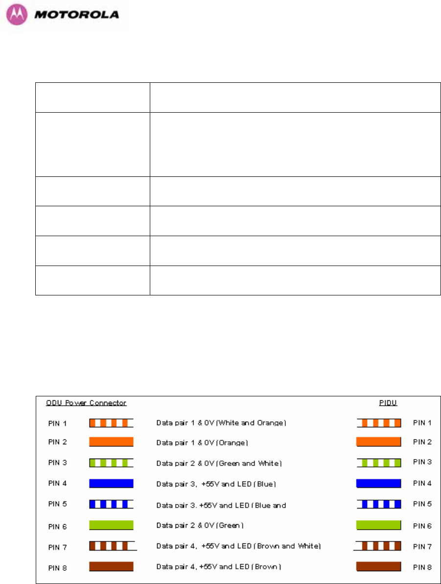
274
23.6 Environmental Specifications
Category Specification
Temperature
ODU: -40°F (-40°C) to 140°F (+60°C)
PIDU Plus: 32°F (0°C) to 104PP
o
PPF(+40°C)
PIDU Plus: -40°F (-40°C) to 140°F (+60°C)
Wind Loading 150mph Max (242kph). See Section 1254H12 for a full description.
Humidity 100% Condensing
Waterproof IP65 (ODU), IP53 (PIDU Plus)
UV Exposure 10 year operational life (UL746C test evidence)
23.7 System Connections
23.7.1 PIDU Plus to ODU and ODU to Network Equipment Connections
Figure 164 - Cable Connection Diagram (T568B Color Coding)

275
Telecoms Connector Pinout Signal Name
Pin 1 E1T1A_TX-
Pin 2 E1T1A_TX+
Pin 3 E1T1A_RX-
Pin 4 E1T1B_TX-
Pin 5 E1T1B_TX+
Pin 6 E1T1A_RX+
Pin 7 E1T1B_RX-
Pin 8 E1T1B_RX+
Table 37 - Telecoms Connection Pin Out

276
MOTOROLA, the stylized M Logo and all other trademarks indicated as such
herein are trademarks of Motorola, Inc. ® Reg. US Pat & Tm. Office. All other
product or service names are the property of their respective owners. © 2007
Motorola, Inc. All rights reserved.
Unit A1, Linhay Business Park
Eastern Road, Ashburton
Devon, TQ 13 7UP, UK
Telephone Support: +1 877 515-0400 (Worldwide)
+44 808 234 4640 (UK)
493Hwww.motorola.com/ptp