Cambium Networks 58XX-T Wireless Ethernet Bridge User Manual 13
Cambium Networks Limited Wireless Ethernet Bridge 13
Contents
- 1. Users Manual
- 2. Handbook Annex A
- 3. Handbook
Handbook Annex A
13 Annex A - Gemini OS 58XXC
13.1 Scope
This Annex details the changes and additional features relevant to the connectorised
variant of the Gemini Product, OS 58XXC.
13.2 Product Description
13.2.1 Hardware
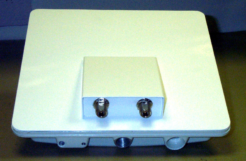
The OS58XXC is a variant designed to provide the system integrator and installer with
the ability to provide extra capability to cope with very difficult radio links compared to
the basic Gemini product. The variant allows the use of a variety of externally mounted
antennas, either Flat Plate or Dish, which have higher gains than provided by the
integrated antenna that is normally used.
The OS 58XXC is shown as Fig 38.
Figure 1 : 58XXC Outdoor Unit
13.2.2 Antenna Choices
The integrated antenna has a gain of 23dBi. External antennas from the list in Table 10
can be used with the OS58XXC. These are approved by the FCC for use with the
product and are basically constrained by the following limits:
• Single Polarisation Flat Plate Antennas – up to 28dBi per antenna
• Single/Dual Polarisation Parabolic Dish Antennas – up to 37.7dBi per polarisation
or antenna
All external antennas – cable loss between OS 58XXC and the antenna ports must not be
less than 1.2dB
13.3 Software/Features
The variant operates in the same way as the basic Gemini product and is released initially
with the feature set of the OS 5815 product. The areas where the functionality is
modified are
13.3.1 Status Page
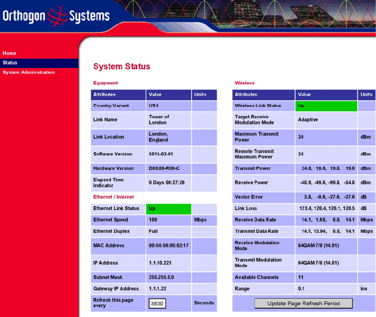
The link loss calculation presented on the Status Page on the management interface has to
be modified to allow for the increased antenna gains at each end of the link. The
manufacturing process of the OS5815C configures the standard hardware of the unit for
use with external antennas. The installer is prompted, as part of the installation process,
to enter the gain of the external antenna(s) and cable losses at each end of the link. Peer-
Peer messaging is used to pass the effective antenna gain to each end of the link so that
the link loss calculations can be correctly computed.
Figure 2 : Example Status Page (showing new hardware Version data for Connector
Version)
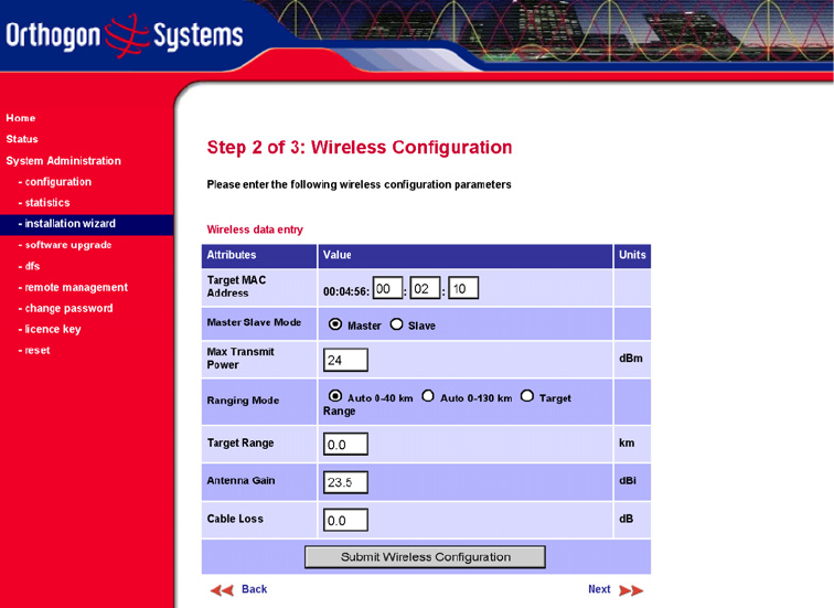
13.3.2 Installation Pages
The installer is prompted to enter the Antenna Gain and Cable Loss (OS 5815C to
antenna) at each end of the link. The Installation Page(s) is shown as Fig 40/41
Figure 3 : Amended Installation Wizard Page
Note: In the event that there is a significant difference in length of the antenna cables for
the two antenna ports, then the average value should be entered.
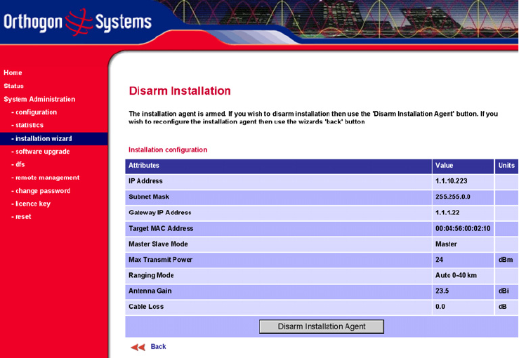
Figure 4 : Amended ‘Disarm Installation’ Page
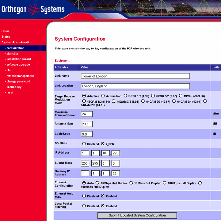
13.3.3 Configuration Pages
The amended Configuration Web page is shown below as Figure 42.
Figure 5 : Amended System Configuration Page
13.4 Gemini Path Calculator
The Gemini Path Calculator described in Para 4.3 of the main user handbook is provided
with additional functionality to allow for the higher gains of the external antennas
permissible with OS 5815C. When the ‘Standard Antenna’ check box in the spreadsheet
is de-selected, the user is offered a pull-down menu of allowed antenna options. When
the required antenna is selected, the appropriate gain is entered in the spreadsheet.
Alternatively, the user can select the ‘Other’ antenna option and enter a gain value to
determine how much antenna gain would be required for a specific link.
13.5 Deployment Considerations
The majority of radio links can be successfully deployed with the OS5815 product. It
should only be necessary to use external antennas where the Link Budget Calculator
indicates marginal performance for a specific link. Examples of this would be where the
link is heavily obscured by dense woodland on an NLOS link or extremely long LOS
links (>80km) over water.

The external antennas can be either dual-polarisation (as the integrated antenna) or two
single polarised antennas can be used in a spatially diverse configuration. It is expected
that the dual-polarisation antennas would normally be used to simplify the installation
process; spatially diverse antennas may provide additional fade margin on very long LOS
links where there is evidence of correlation of the fading characteristics on Vertical and
Horizontal polarisations.
Dual polarisation antennas (with a gain greater than the integrated antenna) are currently
only available in parabolic dish form.
13.6 Regulatory Issues 1
This section applies to products deployed in the USA or where FCC Part 15 regulations
are used for unlicensed radio equipments
13.6.1 Antenna Choice
The antennas allowed to be deployed (in the USA) with the Gemini 5815C are shown in
Table 10
13.6.2 Cable Losses
The FCC approval for the product is based on tests with a cable loss between the unit and
the antenna of 1.2dB at 5.8GHz. The use of lower cable losses with the highest gain
antennas of either type would result in the installation being outside the FCC rules.
As an indication, 1.2dB of cable loss corresponds to the following cable lengths
excluding connector losses (source: Times Microwave).
Cable Length for 1.2dB Cable
Loss at 5.8GHz (ft/m)
LMR100 1.9/0.6
LMR200 4.6/1.4
LMR300 7.25/2.2
LMR400 11.1/3.4
Table 1 : Cable Losses per Length
13.7 Regulatory Issues 2
In countries where FCC regulations are not relevant, installations should conform to any
applicable local regulations for the Equivalent Isotropic Radiated Power (EIRP).
13.8 Link Budget
This is increased by the additional gain of the external antenna(s) less the cable losses.
The improvement in link budget is indicated in Table 9 for representative antennas when
operating in the various modes.

14 inch, Dual
Polar, 23.5dBi
Integrated
Antenna
2ft Single Pol Flat
Plat or Parabolic
Dish, ~28dBi
3ft Single/Dual Pol
Parabolic Dish,
~31.5dBi
4ft Single/Dual Pol
Parabolic Dish,
~34.5dBi
6ft Single/Dual Pol
Parabolic Dish,
~37.7dBi
BPSK 1/2 167 173.6 180.6 186.6 193
QPSK 1/2 163 169.6 176.6 182.6 189
QPSK 2/3 161.1 167.7 174.7 180.7 187.1
16QAM 1/2 156.6 163.2 170.2 176.2 182.6
16QAM 3/4 152.2 158.8 165.8 171.8 178.2
64QAM 2/3 146.7 153.3 160.3 166.3 172.7
64QAM 3/4 144.7 151.3 158.3 164.3 170.7
64QAM 7/8 140.5 147.1 154.1 160.1 166.5
Static Link Budget (dB)
Operating Mode
Table 2 : Static Link Budget for Various Antenna Options
Notes:
Cable Loss is 1.2dB for the External Antennas
Gains shown for external antennas are typical values; specific antennas may have
different gains
Maximum allowed gain is 37.7dBi for a parabolic dish, and 28dBi for flat plate antenna.
Manufacturer Antenna Type Gain (dBi) Flat Plate Parabolic Dish
Andrew Andrew 1-foot Flat Panel, FPA5250D12-N (23.6dBi) 23.6 Y
Andrew Andrew 2-foot Flat Panel, FPA5250D24-N (28dBi) 28 Y
Gabriel Gabriel 1-foot Flat Panel, DFPD1-52 (23.5dBi) 23.5 Y
Gabriel Gabriel 2-foot Flat Panel, DFPD2-52 (28dBi) 28 Y
MTI MTI 17 inch Diamond Flat Panel, MT-485009 (23dBi) 23 Y
MTI MTI 15 inch Dual-Pol Flat Panel, MT-485025/NVH (23dBi) 23 Y
MTI MTI 2 ft Directional Flat Panel, MT-20004 (28dBi) 28 Y
MTI MTI 2 ft Flat Panel, MT-486001 (28dBi) 28 Y
RFS RFS 1-foot Flat Panel, MA0528-23AN (23dBi) 23 Y
RFS RFS 2-foot Flat Panel, MA0528-28AN (28dBi) 28 Y
Telectronics Teletronics 2-foot Flat Plate Antenna, ANT-P5828 (28dBi) 28 Y
Andrew Andrew 2-foot Parabolic, P2F-52 (29.4dBi) 29.4 Y
Andrew Andrew 2-foot Dual-Pol Parabolic, PX2F-52 (29.4dBi) 29.4 Y
Andrew Andrew 3-foot Parabolic, P3F-52 (33.4dBi) 33.4 Y
Andrew Andrew 3-foot Dual-Pol Parabolic, PX3F-52 (33.4dBi) 33.4 Y
Andrew Andrew 4-foot Parabolic, P4F-52 (34.9dBi) 34.9 Y
Andrew Andrew 4-foot Dual-Pol Parabolic, PX4F-52 (34.9dBi) 34.9 Y
Andrew Andrew 6-foot Parabolic, P6F-52 (37.6dBi) 37.6 Y
Andrew Andrew 6-foot Dual-Pol Parabolic, PX6F-52 (37.6dBi) 37.6 Y
Gabriel Gabriel 2-foot High Performance QuickFire Parabolic, HQF2-52-N 28.2 Y
Gabriel Gabriel 4-foot High Performance QuickFire Parabolic, HQF4-52-N 34.4 Y
Gabriel Gabriel 6-foot High Performance QuickFire Parabolic, HQF6-52-N 37.4 Y
Gabriel Gabriel 2-foot High Performance Dual QuickFire Parabolic, HQFD2-52-N 28.1 Y
Gabriel Gabriel 4-foot High Performance Dual QuickFire Parabolic, HQFD4-52-N 34.3 Y
Gabriel Gabriel 6-foot High Performance Dual QuickFire Parabolic, HQFD6-52-N 37.3 Y
Gabriel Gabriel 2-foot Standard QuickFire Parabolic, QF2-52-N 28.5 Y
Gabriel Gabriel 2-foot Standard QuickFire Parabolic, QF2-52-N-RK 28.5 Y
Gabriel Gabriel 2.5-foot Standard QuickFire Parabolic, QF2.5-52-N 31.2 Y
Gabriel Gabriel 4-foot Standard QuickFire Parabolic, QF4-52-N 34.8 Y
Gabriel Gabriel 4-foot Standard QuickFire Parabolic, QF4-52-N-RK 34.8 Y
Gabriel Gabriel 6-foot Standard QuickFire Parabolic, QF6-52-N 37.7 Y
Gabriel Gabriel 2-foot Standard Dual QuickFire Parabolic, QFD2-52-N 28.4 Y
Gabriel Gabriel 2.5-foot Standard Dual QuickFire Parabolic, QFD2.5-52-N 31.1 Y
Gabriel Gabriel 2-foot Standard Dual QuickFire Parabolic, QFD2-52-N-RK 28.4 Y
Gabriel Gabriel 4-foot Standard Dual QuickFire Parabolic, QFD4-52-N 34.7 Y
Gabriel Gabriel 4-foot Standard Dual QuickFire Parabolic, QFD4-52-N-RK 34.7 Y
Gabriel Gabriel 6-foot Standard Dual QuickFire Parabolic, QFD6-52-N 37.7 Y
RadioWaves Radio Waves 2-foot Dual-Pol Parabolic, SPD2-5.2 (28.1dBi) 28.1 Y
RadioWaves Radio Waves 2-foot Parabolic, SP2-5.2 (29.0dBi) 29 Y
RadioWaves Radio Waves 3-foot Dual-Pol Parabolic, SPD3-5.2 (31.1dBi) 31.1 Y
RadioWaves Radio Waves 3-foot Parabolic, SP3-5.2 (31.4dBi) 31.4 Y
RadioWaves Radio Waves 4-foot Dual-Pol Parabolic, SPD4-5.2 (34.4dBi) 34.4 Y
RadioWaves Radio Waves 4-foot Parabolic, SP4-5.2 (34.8dBi) 34.8 Y
RadioWaves Radio Waves 6-foot Dual-Pol Parabolic, SPD6-5.2 (37.5dBi) 37.5 Y
RadioWaves Radio Waves 6-foot Parabolic, SP6-5.2 (37.7dBi) 37.7 Y
RadioWaves Radio Waves 2-foot Parabolic, SP2-2/5 (28.3dBi) 28.3 Y
RadioWaves Radio Waves 3-foot Parabolic, SP3-2/5 (31.4dBi) 31.4 Y
RadioWaves Radio Waves 4-foot Parabolic, SP4-2/5 (34.6dBi) 34.6 Y
RadioWaves Radio Waves 6-foot Parabolic, SP6-2/5 (37.7dBi) 37.7 Y
RFS RFS 2-foot Parabolic, SPF2-52AN or SPFX2-52AN (27.9dBi) 27.9 Y
RFS RFS 3-foot Parabolic, SPF3-52AN or SPFX3-52AN(31.4dBi) 31.4 Y
RFS RFS 4-foot Parabolic, SPF4-52AN or SPFX4-52AN(33.9dBi) 33.9 Y
RFS RFS 6-foot Parabolic, SPF6-52AN or SPFX6-52AN (37.4dBi) 37.4 Y
RFS RFS 2-foot HP Parabolic, SDF2-52AN or SDFX2-52AN (31.4dBi) 31.4 Y
RFS RFS 4-foot HP Parabolic, SDF4-52AN or SDFX4-52AN (33.9dBi) 33.9 Y
RFS RFS 6-foot HP Parabolic, SDF6-52AN or SDFX6-52AN (37.4dBi) 37.4 Y
StellaDoradus StellaDoradus 45 inch Parabolic Antenna, 58PSD113 33.8 Y
Table 3 : Allowed Antennas for Deployment in USA/Canada