Cambium Networks 58XX-T Wireless Ethernet Bridge User Manual Orthogon Systems
Cambium Networks Limited Wireless Ethernet Bridge Orthogon Systems
Contents
- 1. Users Manual
- 2. Handbook Annex A
- 3. Handbook
Users Manual

There’s line-of-sight...
There’s non-line-of-sight...
and then there’s
Orthogon Systems
User Manual
2

1
Orthogon Systems
Gemini System User Manual
May 16, 2003
Ref: PHN-0532-0006
Copyright Information
This document is the confidential property of PipingHot Networks Limited and without its pri-
or written consent may not be copied or released to 3rd parties. © 2003 PipingHot Networks
Limited.
Compliance
Changes or modifications not expressly approved by Orthogon Systems could void the user’s
authority to operate the equipment.
Disclaimer
The parameters quoted in this document must be specifically confirmed in writing before they
become applicable to any particular order or contract. The company reserves the right to make
alterations or amendments to the detail specification at its discretion. The publication of informa-
tion in this document does not imply freedom from patent or other rights of Orthogon Systems
or others.
2
Contents
1 GettingStarted .................. 4
1.1 ForYourSafety ................ 4
1.2 Welcome ..................... 4
1.2.1 About This Guide . . . . . . . . . . . . . 4
1.2.2 Who Should Use This Guide . . . . 5
1.2.3 Service ..................... 5
1.3 Product Description (About
theOS-Gemini) ................ 5
1.3.1 The Outdoor Unit (ODU) . . . . . . . 6
1.3.2 The Indoor Unit (IDU) . . . . . . . . . 6
1.3.3 Mains Power Adaptor . . . . . . . . . 7
1.3.4 Cables and Connectors . . . . . . . . . 8
1.3.5 Surge Arrestor . . . . . . . . . . . . . . . 9
1.3.6 Mounting Brackets . . . . . . . . . . . 10
1.3.7 Configuration and Management . 11
1.4 Warranty .................... 11
2 Product Architecture (More
Detail About The OS-Gemini) . . . . 12
3 General Considerations . . . . . . . . . . 14
3.1 Frequency Planning . . . . . . . . . . . 14
3.2 Distance ..................... 14
3.3 Networking Information . . . . . . . . 14
3.4 Lightning Protection . . . . . . . . . . . 14
3.5 Electrical Requirements . . . . . . . . 15
3.6 Training ..................... 15
4 SitePlanning .................. 16
4.1 Site Selection Criteria . . . . . . . . . . 16
4.1.1 ODU Site Selection . . . . . . . . . . . 16
4.1.2 IDU Site Selection . . . . . . . . . . . . 16
4.2 Path Loss Considerations . . . . . . . 16
4.2.1 Free Space Path Loss . . . . . . . . . 17
4.2.2 Excess Path Loss . . . . . . . . . . . . 17
4.2.3 Fade Margin . . . . . . . . . . . . . . . . 18
4.2.4 Maximum Path Loss . . . . . . . . . 18
4.2.5 Worked Example 1 . . . . . . . . . . . 19
4.2.6 Worked Example 2 . . . . . . . . . . . 19
4.3 MeanPower ................. 20
5 Installation .................... 22
5.1 Preparation . . . . . . . . . . . . . . . . . . 22
5.2 Installation Procedure . . . . . . . . . . 22
5.3 Tools Required . . . . . . . . . . . . . . . 22
5.4 Installation Support . . . . . . . . . . . . 22
5.5 Legal Disclaimer . . . . . . . . . . . . . . 23
5.5.1 Mounting the ODUs .......... 23
5.5.2 Connecting Up . . . . . . . . . . . . . . 25
5.5.3 Mounting The IDU ........... 30
5.5.4 Powering Up . . . . . . . . . . . . . . . . 31
5.5.5 Aligning the ODUs ........... 31
6 Web Page Reference . . . . . . . . . . . . 33
6.1 HomePage .................. 33
6.2 Systems Status Page . . . . . . . . . . . 34
6.3 System Administration Page . . . . . 35
6.3.1 System Configuration Page . . . . 35
6.3.2 Install Pages . . . . . . . . . . . . . . . . 36
6.3.3 Software Upgrade Pages . . . . . . 38
6.3.4 DFSPages ................. 39
6.3.5 SMTP Configuration Page . . . . . 40
6.3.6 Change System
Administration Password . . . . . . 41
6.3.7 Software License Key . . . . . . . . 41
7 FaultFinding .................. 42
8 Specifications . . . . . . . . . . . . . . . . . . 43
8.1 System Specification . . . . . . . . . . . 43
8.2 Safety Compliance . . . . . . . . . . . . 44
8.3 EMC Emissions Compliance . . . . 44
8.4 EMC Immunity Compliance . . . . . 45
8.5 Radio Certifications (type
approvals) ................... 45
8.6 Environmental Specifications . . . . 45
8.7 System Connections . . . . . . . . . . . 46
8.7.1 ODU to IDU Connection . . . . . . 46
8.7.2 Network Connection . . . . . . . . . 46
8.7.3 Power Connection . . . . . . . . . . . 46
9 Lightning Protection . . . . . . . . . . . . 48
10 FAQs ........................ 50
11 Glossary ...................... 51
12 Index ........................ 52

3
List of Figures
1 Typical OS-Gemini Deployment . . . . 5
2 OS-Gemini Outdoor Unit (ODU) . . . . 7
3 OS-Gemini Indoor Unit (IDU) ...... 8
4 OS-Gemini Reset Switch . . . . . . . . . . 9
5 OS-Gemini power adaptor . . . . . . . . 10
6ODU Mounting Configurations . . . . . 10
7 OS-Gemini Layer Diagram . . . . . . . 12
8 Free Space Path Loss at 5.8 GHz . . . 17
9 Fade Margin vs Excess Path
Loss for 99.99% link availability . . 18
10 Worked Example . . . . . . . . . . . . . . . 19
11 Worked Example over a hill . . . . . . 20
12 Mean path loss vs range for
BPSK and 16QAM ............... 20
13 RJ45 Pin Connections . . . . . . . . . . . 27
14 Webpagemenus ............... 33
15 HomePage .................... 33
16 StatusPage .................... 34
17 System Administration Page . . . . . . 35
18 Configuration Page . . . . . . . . . . . . . 35
19 Licence key entry . . . . . . . . . . . . . . . 36
20 Installation page 1 — Internet
Protocol Settings . . . . . . . . . . . . . . . 36
21 Installation page 2 —
Wireless Configuration . . . . . . . . . . 37
22 Installation page 3 —
Confirm Installation . . . . . . . . . . . . 37
23 Installation page 4 —
Configuration Complete . . . . . . . . . 38
24 Software upgrade . . . . . . . . . . . . . . . 38
25 DFSpage ..................... 40
26 SMTPpage ................... 40
27 Passwordpage ................. 41
28 Licensepage .................. 41
29 Fault Finding Guide . . . . . . . . . . . . . 42
30 DC Connection Diagram . . . . . . . . . 46
31 ODU Mounting Positions . . . . . . . . 49
4
1 Getting Started
1.1 For Your Safety
Caution Users and installers should note that the mains power supply is the primary disconnect
device.
Warning Use extreme care when installing antennas near power lines.
Warning Use extreme care when working at heights.
Caution When the system is operational, avoid standing directly in front of the antenna. Strong
RF fields are present when the transmitter is on.The ODU must not be deployed in a location
where it is possible for people to stand or walk inadvertently in front of the antenna.
The Gemini 5810 Outdoor unit must be properly grounded to protect against power surges. It is
the user’s responsibility to install the equipment in accordance with Section 810 of the National
Electric Code, ANSI/NFPA No.70-1984 or Section 54 of the Canadian Electrical Code. These
codes describe correct installation procedures for grounding the outdoor unit, mast, lead-in wire
and discharge unit, size of grounding conductors and connection requirements for grounding
electrodes. It is recommended that installation of the outdoor unit be contracted to a professional
installer.
Caution Safety will be compromised if external quality cables are not used for connections
which will be exposed to the weather.
Caution Safety may be compromised if a different power supply is used than the one supplied
as part of the system.
Caution Safety may be compromised if the screws holding the bracket to the rear of the unit
are removed and reassembled more than once.
1.2 Welcome
Congratulations on the purchase of the OS-Gemini systems from Orthogon Systems. The OS-
Gemini is the latest innovation in high-speed wireless networking that lets you deploy wireless
networks in areas previously unattainable.
1.2.1 About This Guide
This guide covers the installation, commissioning, operation and fault finding of the OS-Gemini
system.
5
1.2.2 Who Should Use This Guide
The guide is for use by the system installer and the end user IT professional.
The system installer will require expertise in the following areas:
•Outdoor radio equipment installation
•Network configuration
•Use of web browser for system configuration, monitoring and fault finding
1.2.3 Service
For unit repair or service, contact your service provider or an authorised Orthogon Systems
distributor for authorisation and shipping instructions.
1.3 Product Description (About the OS-Gemini)
The OS-Gemini has primarily been developed to provide Point-to-Point data connectivity via a
5GHz wireless Ethernet bridge operating at broadband data rates. The OS-Gemini is aimed at
enterprises that have a requirement to connect together the Local Area Network (LAN) of two or
more buildings. Figure 1 illustrates such a deployment. It should be noted that the use of two
links requires a router at each end to provide load balancing and redundancy control which are
not shown.
Building 1 Building 2
Enterprise LAN Enterprise LAN
Power
Adapter
Mains
Supply
Wall
Plate
CAT 5
Patch
CAT 5
Cable
Figure 1 Typical OS-Gemini Deployment
The OS-Gemini offers true non--Line--of--Sight (NLOS) operation by using a combination of Or-
thogonal Frequency Division Multiplex (OFDM) modulation and MultiBeam Space Time Coding
(STC) techniques. These technologies enables the OS-Gemini to drive through foliage and around
buildings to such an extent that almost universal coverage can be expected at short range.
6
The OS-Gemini consists of a pair of identical devices that are deployed one at each end of the
link. At install time the user sets up one unit is set as the Master and the other as the Slave. Either
unit can be configured as master or slave.
Each end of the link consists of:
•An integrated outdoor transceiver unit containing all the radio and networking electronics.
Hereafter referred to as the Outdoor Unit (ODU).
•An indoor passive connection box containing status indicators, DC power connection and
network connection. Hereafter referred to as the Indoor Unit (IDU).
•A ‘mains’ power adaptor.
Power is fed into the IDU from the mains power adaptor via a standard low voltage DC connector.
The network connection is presented to the user at the IDU via an RJ45 socket. Connection
between the ODU and IDU is made using standard CAT 5 UV resistant cable. The spare twisted
pairs of the cable are used to feed power from the IDU to the ODU.
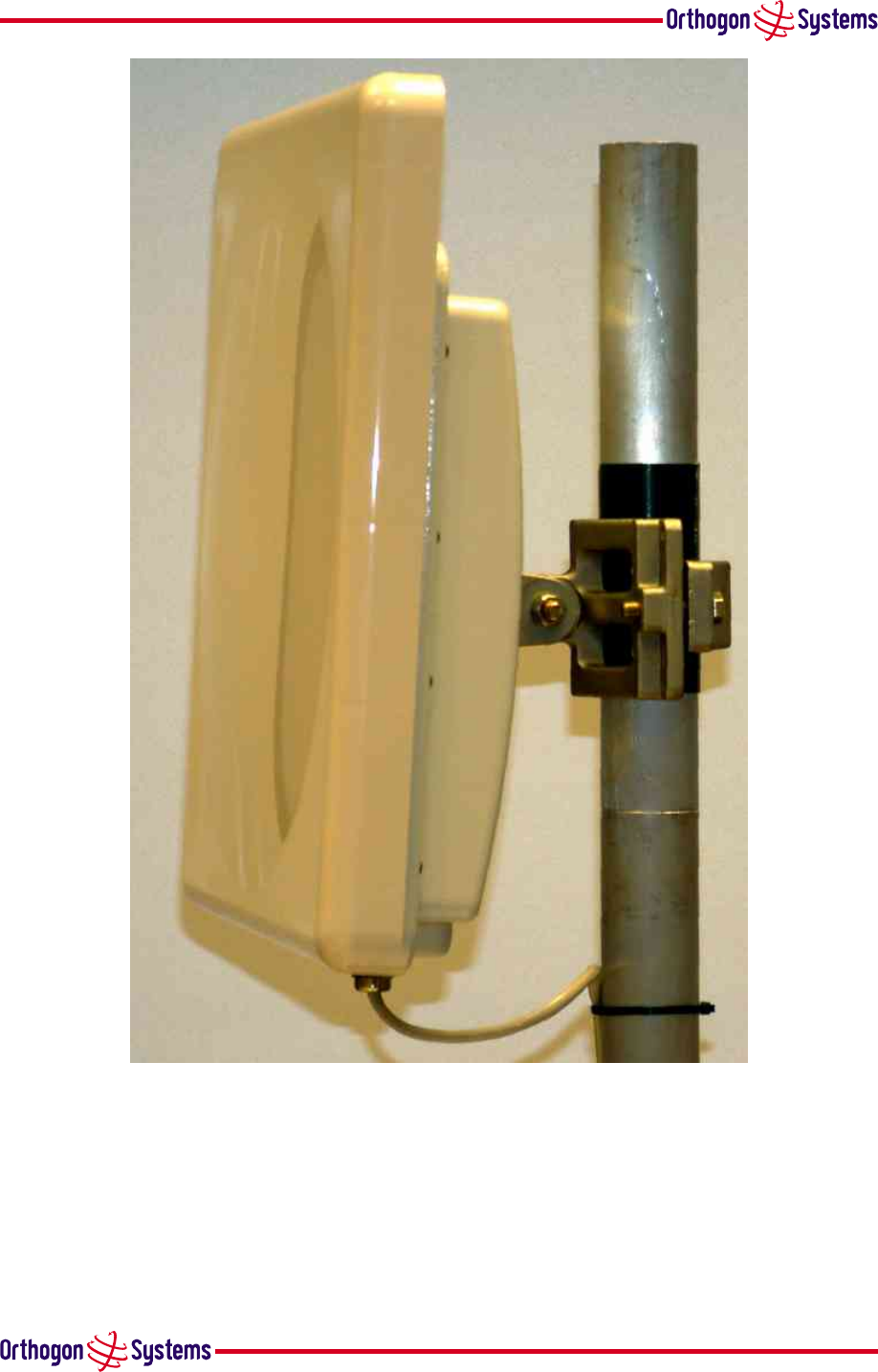
1.3.1 The Outdoor Unit (ODU)
The ODU is a self-contained unit. It houses both radio and networking electronics. The unit is fed
by a single CAT 5 UTP cable. Power is fed to the unit via the brown/brown-white pair connected
to pins 7 and 8 of the RJ45 plugs and sockets employed. It should be noted that this powering
arrangement is not standard Power-over-Ethernet (POE). The OS-Gemini ODU should only be
deployed using the supplied OS-Gemini Indoor Unit (IDU).
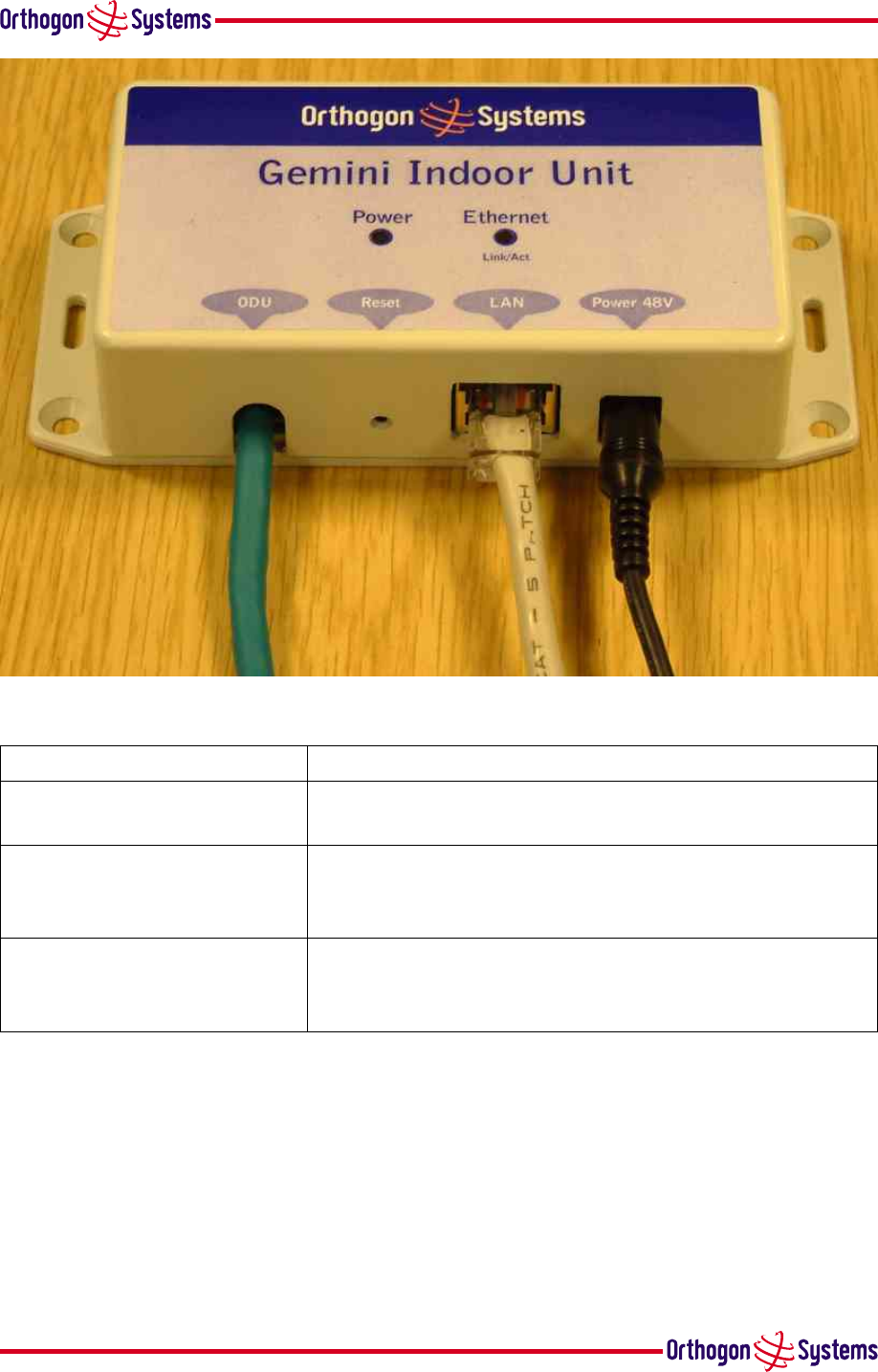
1.3.2 The Indoor Unit (IDU)
The OS-Gemini IDU is a passive device used to inject the DC supply voltage into the cable con-
necting the IDU to the ODU. The IDU also houses status indicators driven from the ODU over the
blue/blue-white pair connected to pins 4 and 5 of the RJ45 plugs and sockets employed.
The front panel contains indicators showing the status of the power and Ethernet connections.
•the power indicator is illuminated when the IDU is receiving 48 volts from the power adaptor.
•the Ethernet indicator illuminates when the ODU is powered; it flashes when there is Ethernet
activity.
The bottom of the IDU contains the Ethernet connection via RJ45 socket, the power connection,
an entry point for IDU-ODU cabling and the reset button.
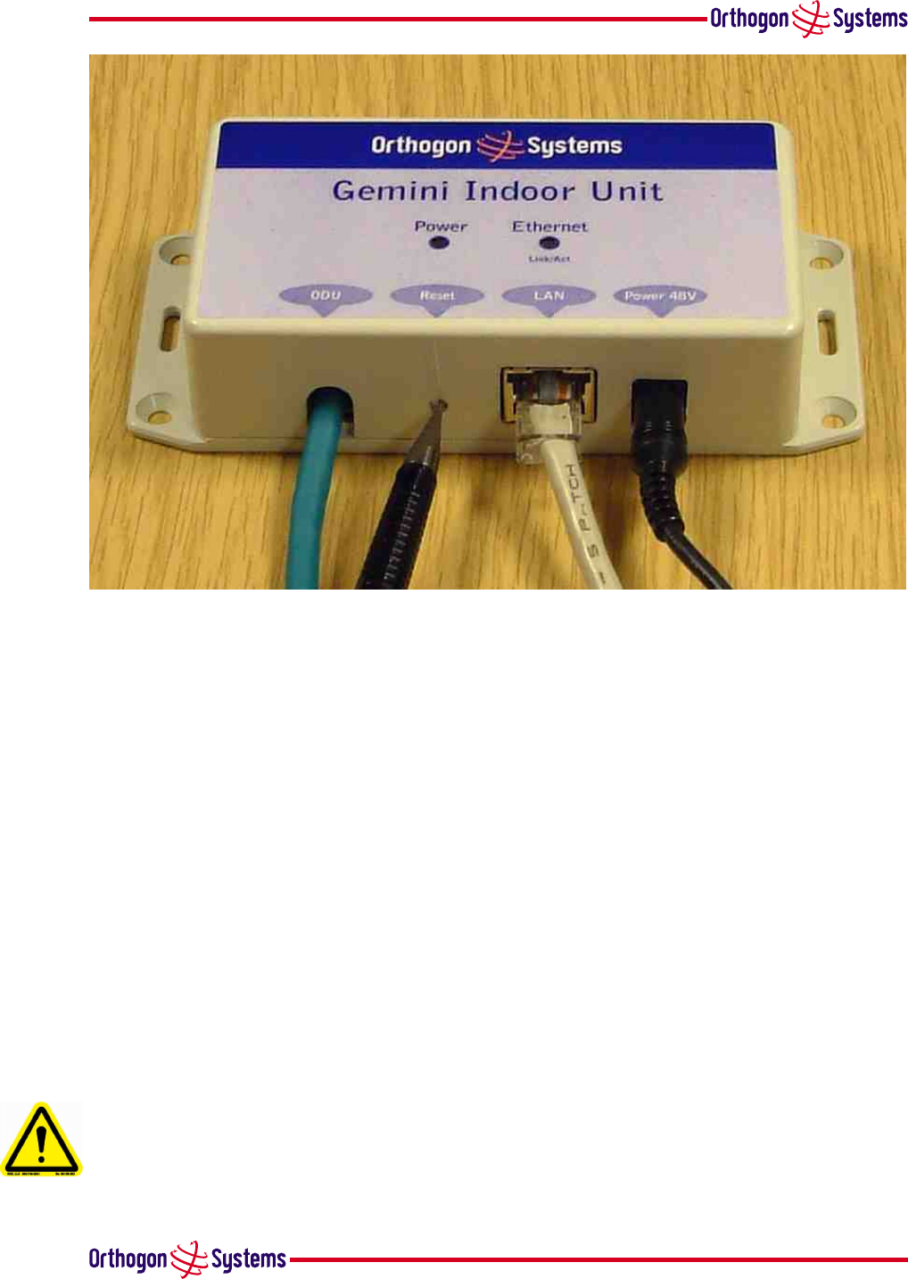
The IDU also houses a reset switch. This reset switch is used for various purposes identified in
table 1.
reset IP switch
7
Figure 2 OS-Gemini Outdoor Unit (ODU)
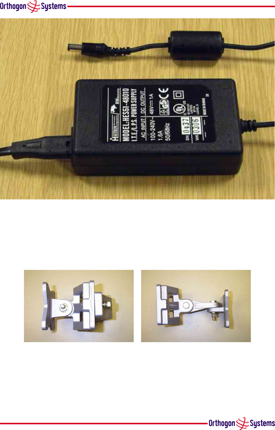
1.3.3 Mains Power Adaptor
The mains power adaptor is an in-line power supply which provides a 48 Volt DC output to supply
power to the IDU /ODU
Caution Safety may be compromised if a different power supply is used instead of the one
supplied as part of the system.
8
Figure 3 OS-Gemini Indoor Unit (IDU)
Reset Button Depression Action
Momentary This is the same as a power cycle. It simply restarts the
unit using the same configuration and software as before.
More than 10 secs This resets the configuration to factory defaults. All
parameters will need to be reentered including the web
page which will have returned to 10.10.10.10.
While connecting power for
more than 15 secs after power
is applied
This resets to factory defaults including to the initial
software load.
Table 1 Reset actions
1.3.4 Cables and Connectors
The cable used to connect the IDU to the ODU can be any standard CAT 5 type provided that it is
suitable for outdoor deployment. Orthogon Systems recommends that cables to the specification
below are used.
NEC/CEC: CMR(ETL) C(ETL) 75C SUN RES OIL RES II
9
Figure 4 OS-Gemini Reset Switch
Failure to use the recommended (or equivalent) standard of cable may invalidate the systems
safety certification.
The IDU/ODU cable may be unscreened (UTP) or screened (STP). However, unscreened cables re-
duce the system’s ability to cope with nearby lightening strikes. If lightening activity is common
in the area of deployment, the use of screened cable is highly recommended.
The connection between the IDU and users equipment can be made using any standard CAT5 UTP
patch cable. The RJ45 Ethernet connection is presented as a piece of network equipment. How-
ever as automatic MDI/MDI-X sensing and pair swapping is employed a crossed or non-crossed
Ethernet patch cable can be used for connection to another piece of networking equipment or
directly to end user equipment.
It should be noted that the IDU provides continuity between the screen on the ODU-IDU cable and
screen on the IDU-User equipment cable. If continuity of the screening is desired from the ODU
to the users equipment, CAT 5 STP cable and connectors should be used for the latter connection.
1.3.5 Surge Arrestor
The IDU does not provide lightning or surge suppression. Should lightning or surge suppression
be required a separate Ethernet surge suppressor should be used and appropriately earthed. Suit-
able surge suppressors can be sourced from your Orthogon Systems distributor or re-seller. The
ODU is protected through built-in surge suppression as standard.
10
Figure 5 OS-Gemini power adaptor
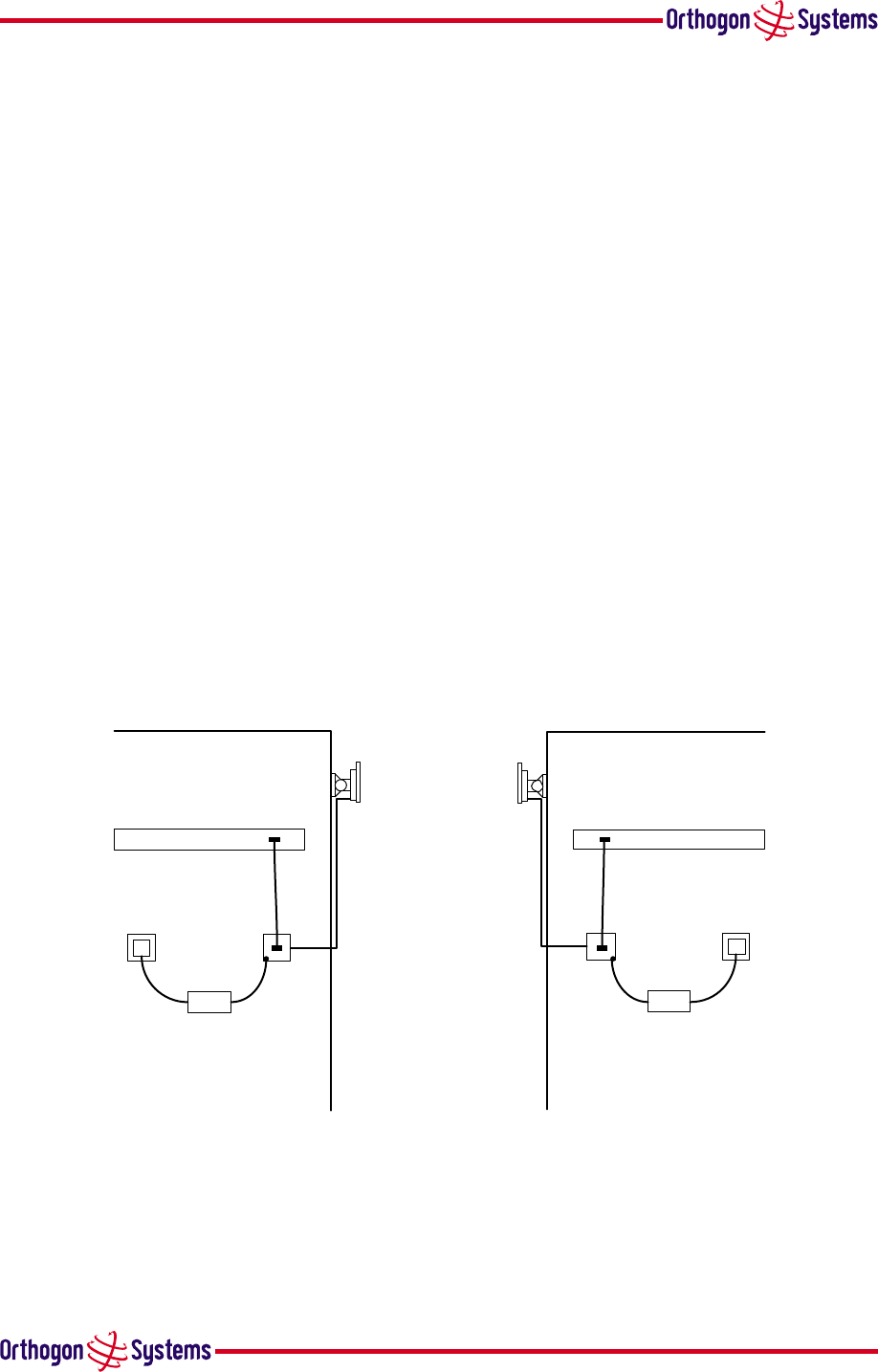
1.3.6 Mounting Brackets
The OS-Gemini ODU is supplied with a mounting bracket suitable for mounting the ODU to a pole
of 50mm to 75mm in diameter or to a flat surface. For more details on mounting see section 5
“Installation”
Pole Wall
Figure 6 ODU Mounting Configurations
The bracket allows for adjustment in both azimuth and elevation. The bracket can be split,
allowing one half to mounted to the ODU and the other half to the pole or wall prior to installation.
This allows the installer to take the weight of the unit on a single mounting bolt while fitting the
retaining nut and washers.

11
The OS-Gemini IDU can either be desk or wall mounted. The preference is wall mounted with
the cables dressed to a skirting board or cable channel. Wall mounting is achieved by screwing
through the mounting lugs on either side of the unit.
1.3.7 Configuration and Management
Configuration and Management of the OS-Gemini is implemented using an inbuilt web server
hosting a number of Configuration and Management web pages. This approach allows Configu-
ration and Management to be carried out on any standard web browsing technology. Connection
to the OS-Gemini is via the Ethernet connection carrying the bridge network traffic. Connection
to the unit is via a preset IP address. This address can be changed via the Network Interface Con-
figuration web page. A full explanation of the available web pages and their use can be found in
section 6 “Web Page Reference”.
1.4 Warranty
Orthogon Systems offers a warranty covering a period of 1 year from the date of purchase by
the end customer. If the product is found to be defective during the warranty period, Orthogon
Systems Ltd. will repair or replace the product with the same or a similar model, which may
be a reconditioned unit, without charge for parts or labour. IN NO EVENT SHALL ORTHOGON
SYSTEMS BE LIABLE TO YOU OR ANY OTHER PARTY FOR ANY DIRECT, INDIRECT, GENERAL, SPE-
CIAL, INCIDENTAL, CONSEQUENTIAL, EXEMPLARY OR OTHER DAMAGE RISING OUT OF THE USE
OR INABILITY TO USE THE PRODUCT (INCLUDING, WITHOUT LIMITATION, DAMAGES FOR LOSS OF
BUSINESS PROFITS, BUSINESS INTERRUPTION, LOSS OF BUSINESS INFORMATION OR ANY OTHER
PECUNIARY LOSS, OR FROM ANY BREACH OF WARRANTY, EVEN IF ORTHOGON SYSTEMS LTD. HAS
BEEN ADVISED OF THE POSSIBILITY OF SUCH DAMAGES. (Some states do not allow the exclusion
or limitation of incidental or consequential damages, so the above exclusion or limitation may
not apply to you.) IN NO CASE SHALL ORTHOGON SYSTEMS’ LIABILITY EXCEED THE AMOUNT
YOU PAID FOR THE PRODUCT.
12
2 Product Architecture (More Detail About The OS-Gemini)
The OS-Gemini consists of an identical pair of units deployed one at each end of the link. The
radio link operates on a single frequency channel using Time Division Duplex (TDD). One unit is
deployed as a master and the other as a slave. The master unit takes responsibility for controlling
the link in both directions.
The non-Line-of-Sight (nLoS) aspects of the product are provided by multi-beam space time
coding, coupled with OFDMmodulation with a dispersion capability of 10 microseconds in both
directions.
The OS-Gemini has been developed to operate in license exempt frequency bands for example
the ETSI 5.8 GHz C band (5.725–5.875 GHz) and the USA 5 GHz ISM band (5.725–5.850 GHz).
The OS-Gemini has been designed to coexist with other users of the band in an optimal fashion
using a combination of Transmit Power Control (TPC), Dynamic Frequency Selection (DFS) and
Antenna beam shape.
In order to maintain link availability, the product employs adaptive modulation techniques that
reduce the data rate in severe or adverse conditions.
The OS-Gemini operates as a standard IEEE 802.3 Ethernet bridge as defined in IEEE 802.1. The
OS-Gemini is implemented as a learning bridge. A learning bridge builds up a picture of which
addresses are connected to which port. This means that it will not re-transmit a packet if it knows
that the destination address is connected to the same port on which the bridge saw the packet.
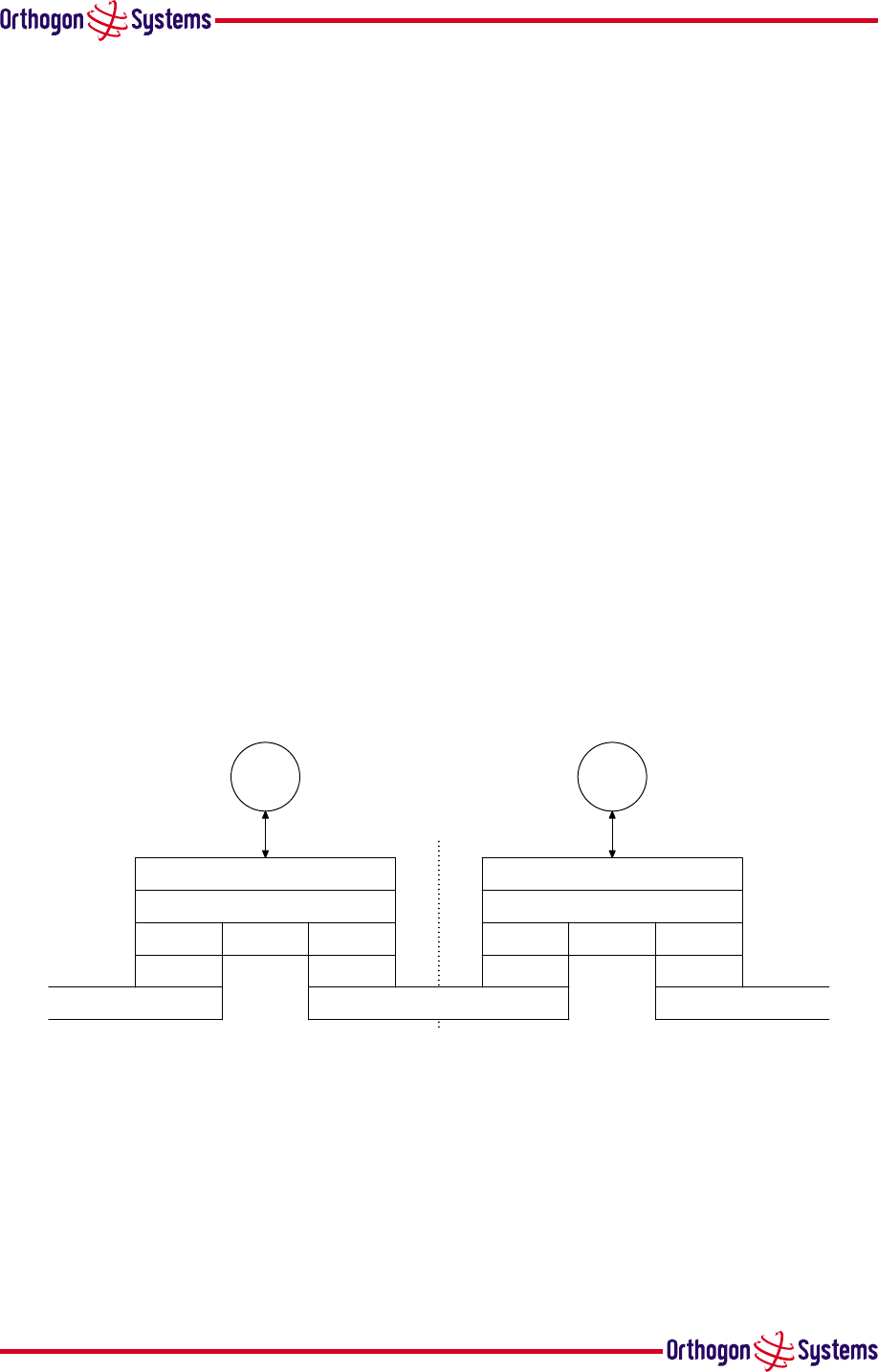
Figure 7 illustrates the OS-Gemini layer diagram.
Ethernet
PHY
DLC Bridging
Network(IP)
Transport(TCP, UDP)
DLC
PHY
http
5 GHz Wireless
PHY
DLC Bridging
Network(IP)
Transport(TCP, UDP)
DLC
PHY
Ethernet
http
Figure 7 OS-Gemini Layer Diagram
The OS-Gemini functionality has been extended to encompass the IEEE 802.1q sub-specification
IEEE 802.1p. IEEE 802.1p allows the Ethernet packets to be extended by 8 bytes to include the
IEEE 802.1q VLAN Tag and VLAN Priority/ID with VLAN ID set to 0 and the packet priority set to
0-7. The OS-Gemini will forward all VLAN tagged packets regardless of the VLAN ID value.
Each unit in the link is manageable through an IP connection. Standard IP protocols are utilised
for all management functions e.g. HTTP,TFTP, etc. The OS-Gemini is fully software upgrade-
able. New software images are first downloaded from the Orthogon Systems support web site

13
(www.orthogonsystems.com/support/download) to a convenient platform. The image
is then uploaded to the ODU via the web management page described in section 6.3.3 “Software
Upgrade Pages”. The compressed image is first loaded into RAM and check summed. If the
compressed image transfer has completed successfully the image is decompressed and written to
Flash memory. On completion of this process the unit will re-boot using the newly downloaded
image. Should this process fail the unit will revert to a protected compressed image installed
during manufacturing to allow the unit to be recovered.

14
3 General Considerations
3.1 Frequency Planning
The OS-Gemini is capable of operating in the whole frequency range 5.725 to 5.875 GHz
(defined as the ETSI 5 GHz C band) but for the USA is optimised for the ISM band (5.725-
5.850 GHz), utilising a 10 MHz wide channel. Setting of the operating frequency channel is
automatic and is carried out by the built-in Dynamic Frequency Selection (DFS) functionality.
The user can configure the OS-Gemini to avoid using certain frequencies to prevent interference
to other users of the band and prevent operation in parts of the band containing interference. The
use of this functionality is described in detail in section 6.3.4 “DFS Pages”.
3.2 Distance
The OS-Gemini will operate at ranges from 100m to 40 km. Operation of the system will depend
on obstacles in the path between the units. Operation at 40km will require a Line of Sight
(LoS) path. Operation at 100m could be achieved with one unit totally obscured from the other
unit, but with the penalty of transmitting at higher power in a non-optimal direction, thereby
increasing interference in the band. This subject is covered in more detail in section 4.2 “Path
Loss Considerations”.
3.3 Networking Information
The OS-Gemini operates as a transparent Ethernet bridge. Each unit requires an IP address.
This IP address is for management purposes only; it does not play any part in the operation on
the system. IP addresses are assigned during initial configuration as described in section 5.2
“Installation Procedure”.
3.4 Lightning Protection
The amount of lightning protection is dependant on regulatory requirements and the end user
requirements. The standard OS-Gemini ODU is fitted with surge limiting circuits and other fea-
tures to minimise the risk of damage due to nearby lightning strikes. These standard features
may require some additional equipment to be configured as part of the system installation to be
fully effective. Orthogon Systems recommends the use of screened cable and surge arrestor to
protect connected equipment from nearby strikes.
Note: The OS-Gemini is not design to survive direct lightning strikes. For this reason
the unit should not be installed as the highest point in a localised area, unless
specific precautions are taken. See section 9 “Lightning Protection”.

15
3.5 Electrical Requirements
The OS-Gemini is supplied with a variable input voltage in-line power supply unit. This unit is
supplied with mains cables suitable for the country of sale. The OS-Gemini requires one mains
supply outlet at each end of the link.
3.6 Training
Installation training courses can be purchased from Orthogon Systems. Self paced Computer
Aided Instruction (CAI) courses can be purchased and downloaded from the Orthogon Systems
website. Tailored courses can be supplied at your own premises or at Orthogon Systems HQ. See
http://www.orthogonsystems.com/training for more details.

16
4 Site Planning
4.1 Site Selection Criteria
The following are guidelines for selecting the installation location of the OS-Gemini ODU and
IDU.
4.1.1 ODU Site Selection
When selecting a site for the ODU the following should be taken into consideration:
•That it is not possible for people to stand or walk inadvertently in front of the antenna.
•Height and location to achieve the best radio path
•Height in relation to other objects with regard to lightning strikes
•Protection from the elements
•Aesthetics and planning permission issues
•Distance from IDU and connected equipment (Maximum cable run ODU to connected equip-
ment is 100m)
•Distance from the IDU to the ODU (Maximum cable run IDU to ODU is 60m)
4.1.2 IDU Site Selection
When selecting a site for the IDU the following should be taken into consideration:
•Availability of a mains supply
•Accessibility for viewing status indicators (See section 1.3.2 “The Indoor Unit (IDU)” and
section 7 “Fault Finding”
•Distance from ODU and connected equipment (Maximum cable run ODU to connected equip-
ment is 100m)
•Distance from the ODU to the IDU (Maximum cable run ODU to IDU is 60m)
4.2 Path Loss Considerations
The path loss is the amount of attenuation the radio signal undergoes between the two ends of the
link. The path loss is the sum of the attenuation of the path if there were no obstacles in the way
(Free Space Path Loss), the attenuation caused by obstacles (Excess Path Loss) and a margin to
allow for possible fading of the radio signal (Fade Margin).
LFree Space +LExcess +LFade <LCapability (1)
where
LFree Space = Free Space Path Loss dB
LExcess = Excess Path Loss dB
LFade = Fade Margin Required dB
LCapability = Equipment Capability dB
17
From the above calculation a rough idea of whether the link will work and be reliable can be
obtained. This is the best estimate that can be achieved without the use of sophisticated radio
planning tools and expensive high-resolution terrain data. The only way to confirm the calcu-
lation is to install the units, complete the installation process and monitor the link for a period
of time. To ensure that the link is reliable through all environmental changes associated with
the changing seasons this monitoring should be continued for a year. In applications where the
OS-Gemini forms part of a high availability system monitoring of the radio signals should be
built-in as part of the end users day-to-day preventative maintenance schedule.
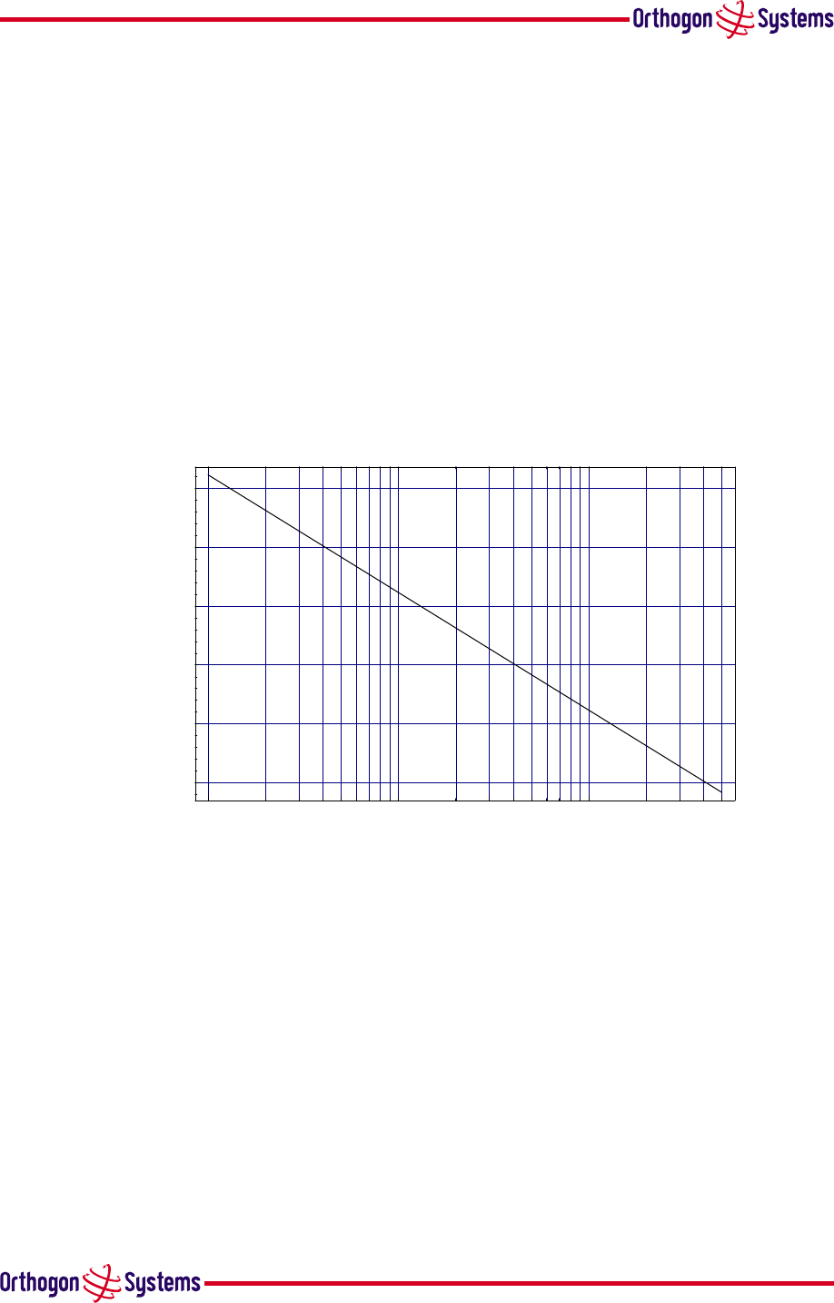
4.2.1 Free Space Path Loss
The Free Space Path Loss is the loss incurred along a Line of Sight path between the two end
point of the radio link.
0.1 0.5 1 5 10 50
range km
-140
-130
-120
-110
-100
-90
dB
Free Space Path Loss
Figure 8 Free Space Path Loss at 5.8 GHz
4.2.2 Excess Path Loss
The Excess Path Loss is the loss incurred due to obstacles between the two end points of the
radio link. The exact attenuation caused by each object is an approximate science. The following
figures should be used for guidance only.
•Approximately 20 dB per Tree
•Approximately 0-30 dB per obstruction that would cause the line of sight to bend by 0-10°
It should be noted that there is a theoretical area around the line of sight of an antenna, called the
Fresnel Zone, which can affect the signal strength. Objects that penetrate the Fresnel Zone can
create out of phase reflections that cancel the wanted signal. Objects near the line of sight of the
18
antenna will add to the excess path loss. Calculations of excess path loss should take this into
consideration using values approximately half those used for objects that obstruct the line of site
of the antenna. For a thorough understanding of this refer to ITU P526.
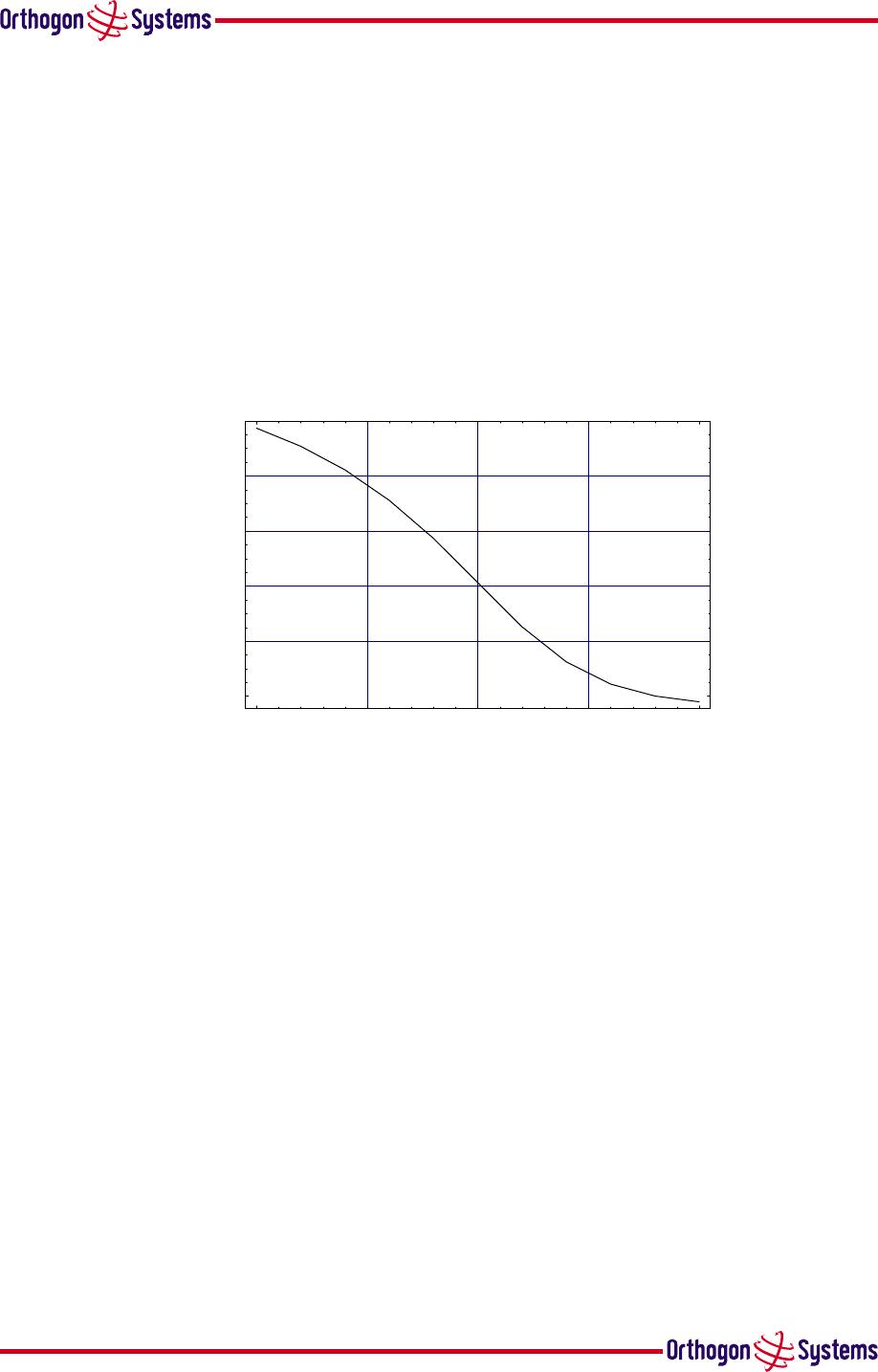
4.2.3 Fade Margin
A Fade Margin needs to be applied to link budget to take into account changes in the radio path
caused by changes in objects surrounding or in the propagating path. e.g. moving objects such
as traffic or the changes in foliage brought on by seasonal change. The fade margin used in the
calculation is a function of excess path loss. The fade margin requirement should be taken from
figure 9 using the excess path loss calculated above.
0 10 20 30 40
Excess Path Loss dB
-12
-10
-8
-6
-4
Fade Margin dB
Fade Margin Required
Figure 9 Fade Margin vs Excess
Path Loss for 99.99% link availability
The use of MultiBeam Space-Time-Coding allows the OS-Gemini to achieve 99.99% availability
even in a totally obscured radio link operating with radio path fading up to 12dB. This graph
should not be used for other products which may need nearly 40 dB fade margin for 30 dB excess
path loss
4.2.4 Maximum Path Loss
The Maximum Path Loss is the total path attenuation that the system can withstand and still
maintain 99.99% availability. Due to different spectrum licensing conditions in different regions
the Maximum Path Loss varies from county to country due to allowable output power differences.
In the USA this budget is 164dB for BPSK and 150 dB for 16QAM.
19
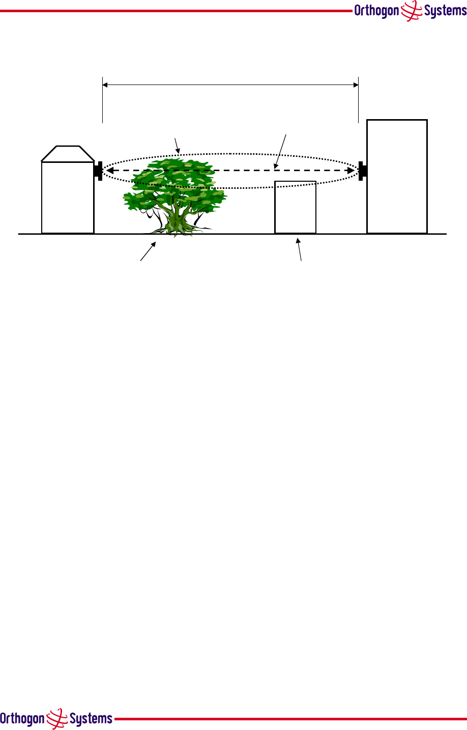
4.2.5 Worked Example 1
2000m
Fresnel Zone
Line of Sight Obstruction Fresnel Zone penetration
Line of Sight
Figure 10 Worked Example
This example of figure 10 shows a case where a tree obscures the Line of Sight and the Fresnel
Zone has a building intrusion.
In this example:
•Free Space Path Loss = 114 dB
•Excess Path Loss for Line of Sight Obstruction = 20 dB
•Excess Path Loss for Fresnel Zone penetration = 10 dB
•Total Excess Path Loss = 30dB
•Required Fade Margin from above look up chart = 11 dB
Calculation:
114 dB + 30 dB + 11 dB = 155 dB
The result of this calculation shows that this scenario would work with margin using the allowed
US power level (164 dB max path loss). The normal operational mode will be 16QAM but there
will be occasional drops to BPSK mode.
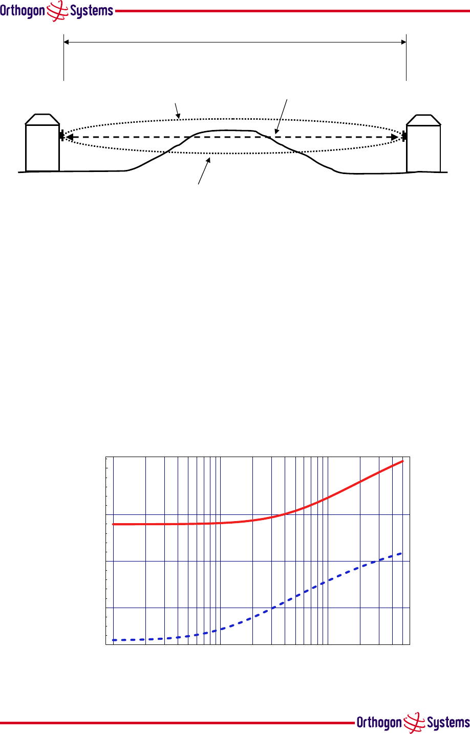
4.2.6 Worked Example 2
This example in figure 11 shows a case where the Line of Sight is obstructed by a terrain obstacle.
In this example:
•Free Space Path Loss = 120 dB
•Excess Path Loss for Line of Sight Obstruction = 20 dB
•Required Fade Margin from above look up chart = 8 dB
20
4000m
Fresnel Zone
Line of Sight Obstruction
Line of Sight
Figure 11 Worked Example over a hill
Calculation:
120 dB + 20 dB + 8 dB = 148 dB
The result of this calculation shows that this scenario would work continuously at 16QAM.
4.3 Mean Power
A Web Management page for Gemini has an important indicator of mean path loss. This is
shown in figure 16. Also on this Web Page is the range. Figure 12 gives the maximum mean
path loss vs range for guaranteeing that Gemini is installed in a position that will give 99.99%
availability. Note: The web page display is for the previous hour and the full fade cycle may not
be traversed for many days depending upon the components causing the fading.
0.1 0.5 1 5 10 50
range km
140
145
150
155
dB
Mean Path Loss BPSK16QAM
Figure 12 Mean path loss vs range for BPSK and 16QAM

21
The blue dashed line is for 16QAM and the solid red line of for BPSK.

22
5 Installation
Orthogon Systems recommends that only qualified personnel undertake the installation of an
OS-Gemini system.
5.1 Preparation
Before proceeding with the installation you should:
•Check the contents of all packages against the parts lists shown in the packing list.
•Ensure that you have the correct tools for the job
•Ensure that you are qualified to undertake the work
•Ensure that you have taken the correct safety precautions.
•Completed the site planning as described in section 4 “Site Planning”.
5.2 Installation Procedure
The OS-Gemini installation procedure consists of the following steps:
•Mounting the ODUs
•Connecting up
•Mounting the IDUs
•Powering Up
•Aligning the ODUs
5.3 Tools Required
The following tools are required to install the OS-Gemini
•Two 13mm Spanners
•4 mm hexagonal key
•Phillips screwdrivers of various sizes
•RJ45 Crimp Tool
5.4 Installation Support
On-line installation support and contact details for your regional support can be found at: http:
//www.orthogonsystems.com/support/installation
A Frequently Asked Questions (FAQs) section can be found in section 10 “FAQs”. Further and
more up to date FAQs may be found at: http://www.orthogonsystems.com/support
/FAQ

23
5.5 Legal Disclaimer
IN NO EVENT SHALL ORTHOGON SYSTEMS BE LIABLE FOR ANY INJURY TO ANY PERSONS OR ANY
DAMAGE CAUSED DURING THE INSTALLATION OF THE ORTHOGON SYSTEMS OS-GEMINI PROD-
UCT.
5.5.1 Mounting the ODUs
The ODU mounting bracket is designed to ease installation by allowing the bracket to be split
into two and be brought back together using a single bolt fixing. The ODU mounting bracket
is designed for both pole and wall mounting. The ODU should be mounted using the following
steps:
24
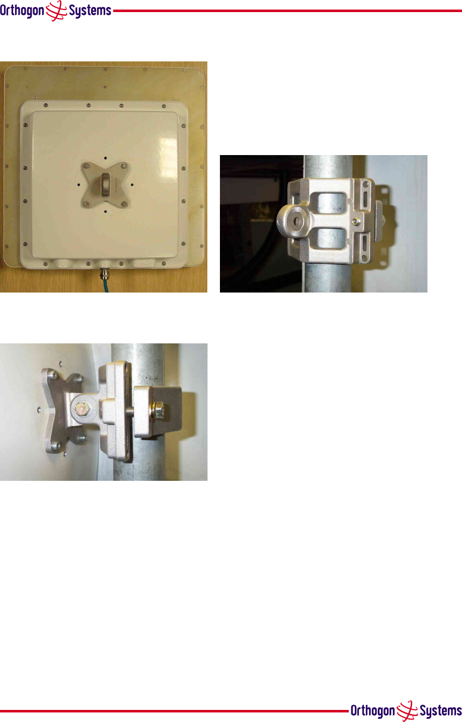
5.5.1.1 Pole Mounting
Step 1: Mount the ODU half of the
bracket to the ODU (Note: orientation)
Step 2: Mount other half
of the bracket to the pole.
Step 3: Mate the two halves
of the bracket together and
tighten the nut and bolt.
25
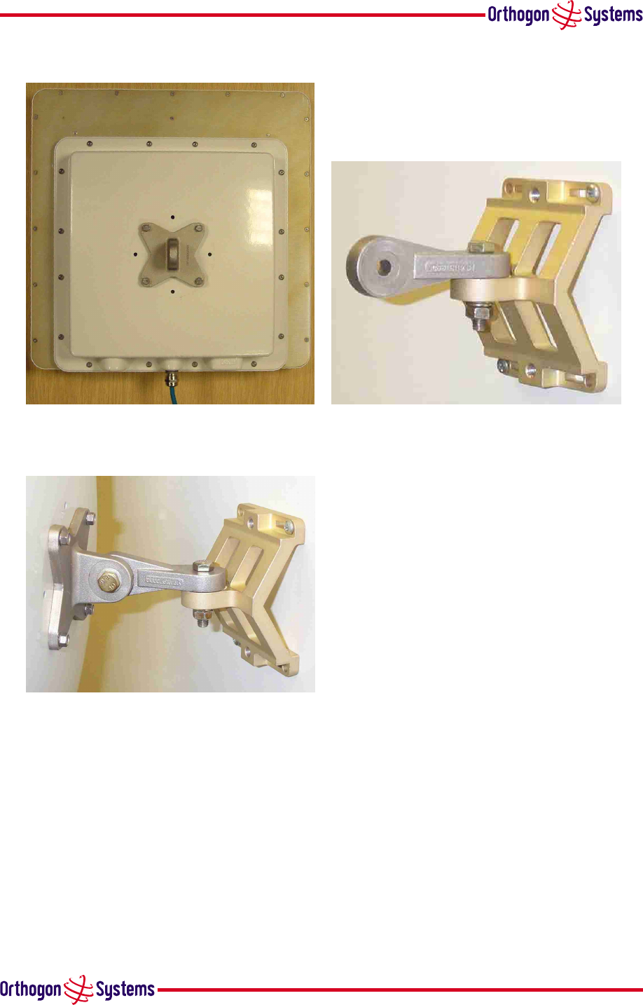
5.5.1.2 Wall Mounting
Step 1: Mount the ODU half of the
bracket to the ODU (Note: orientation).
Step 2: Mount other half
of the bracket to the wall.
Step 3: Mate the two halves
of the bracket together and
tighten the nut and bolt.
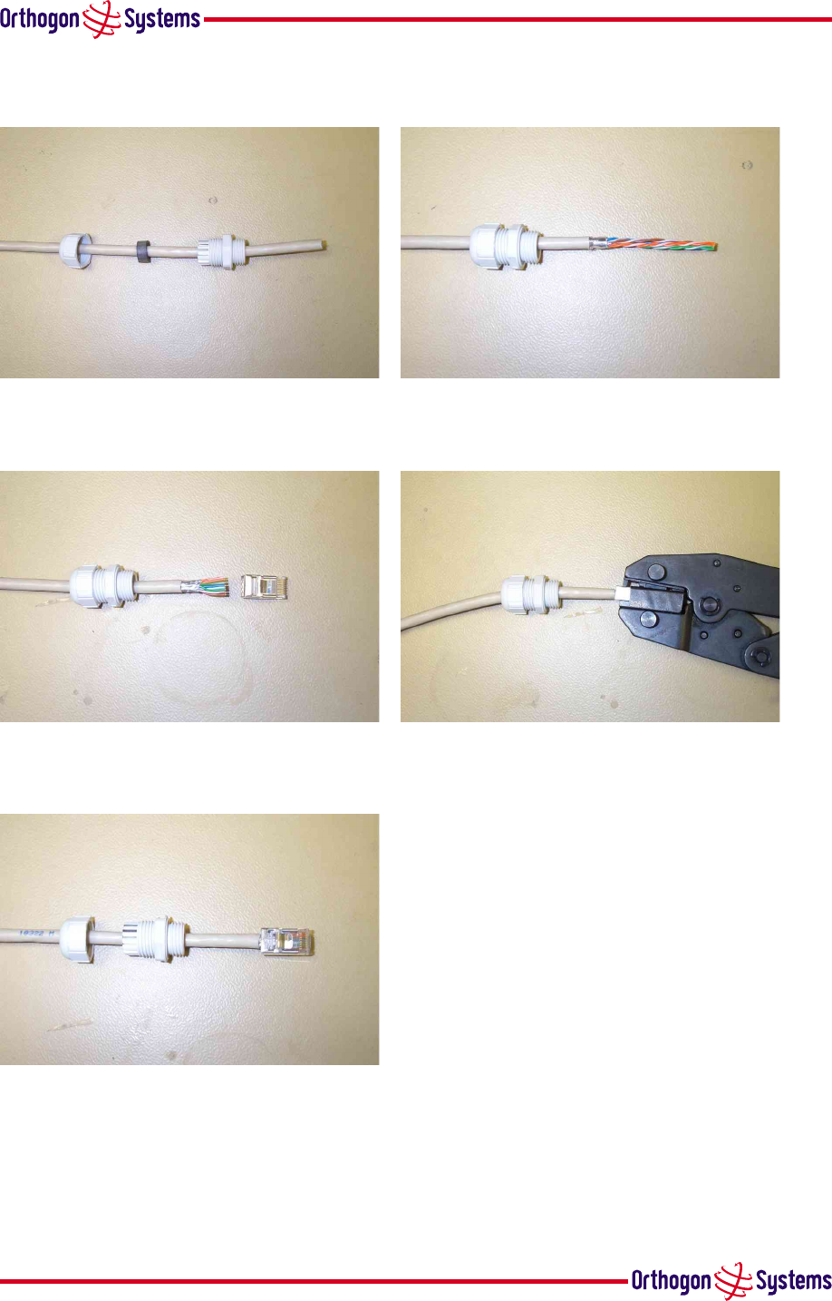
5.5.2 Connecting Up
5.5.2.1 Preparing The Cable — RJ45 connections
Cables with the ODU end already prepared can be purchased from your reseller or distributor in
lengths up to 60m. (Note that the maximum length between the IDU and ODU is 60m.) Those
wishing to source their own cables and connectors (see section 1.3.4 “Cables and Connectors” above)
26
should follow the following instructions along with the cable and connector suppliers instruc-
tions:
Step 1: Assemble gland
on cable as shown
Step 2: Strip the outer insulation
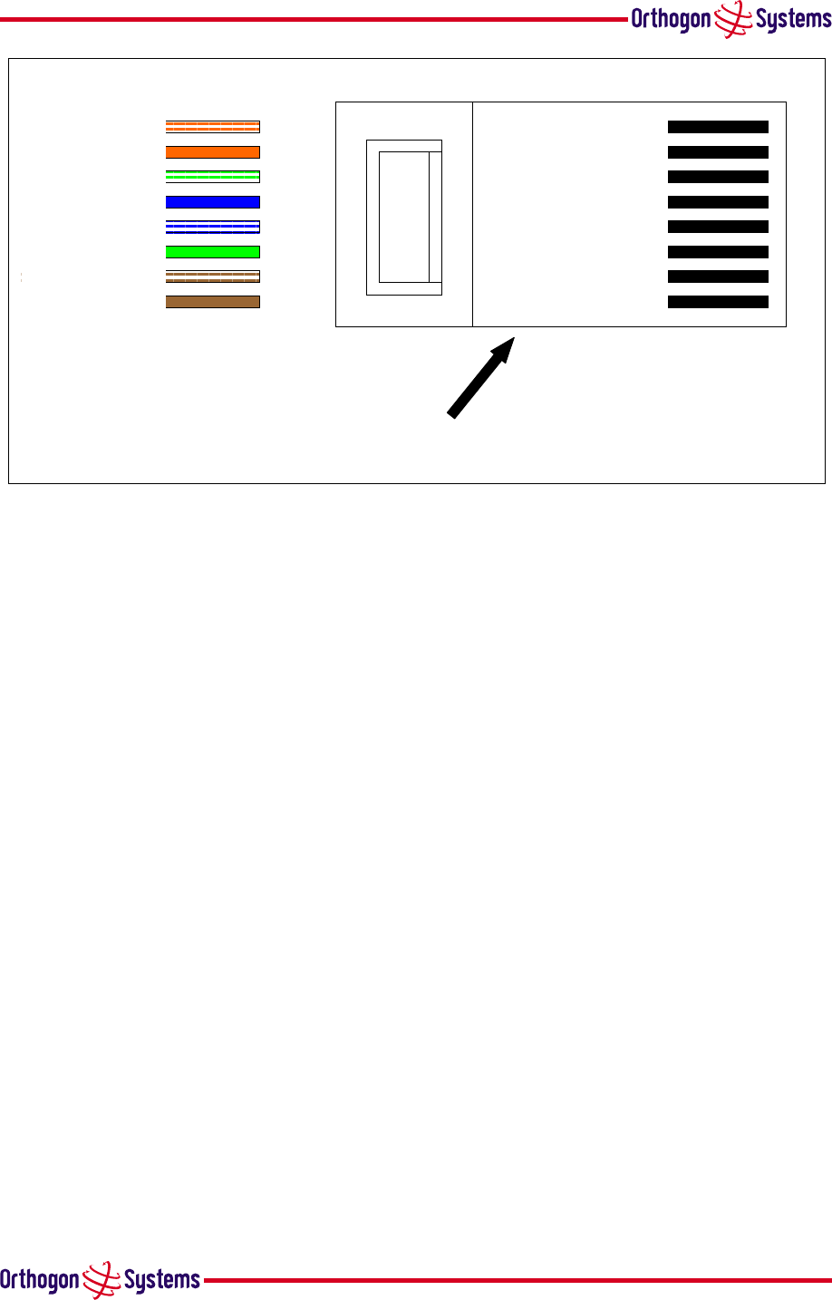
Step 3: Arrange conductors as
shown in Figure 13 and cut to length
Step 4: Insert conductors and crimp
Figure 11 - Completed ODU connector
Both ends of the ODU to IDU cable are terminated in the same way. The above procedure should
be repeated for the IDU end of the cable when the cable routing process is complete.
Note: The IDU end of the cable does not employ a cable gland.
27
White/Orange
Orange
White/Green
Blue
White/Blue
Green
White/Brown
Brown
Pin 1
Pin 2
Pin 3
Pin 4
Pin 5
Pin 6
Pin 7
Pin 8
Lock tab underneath
Figure 13 RJ45 Pin Connections
5.5.2.2 Making the Connection At The ODU
The following procedure describes how connection is made at the ODU. It is often easier to carry
out this procedure on the ground or a suitable surface prior to mounting the ODU.
28
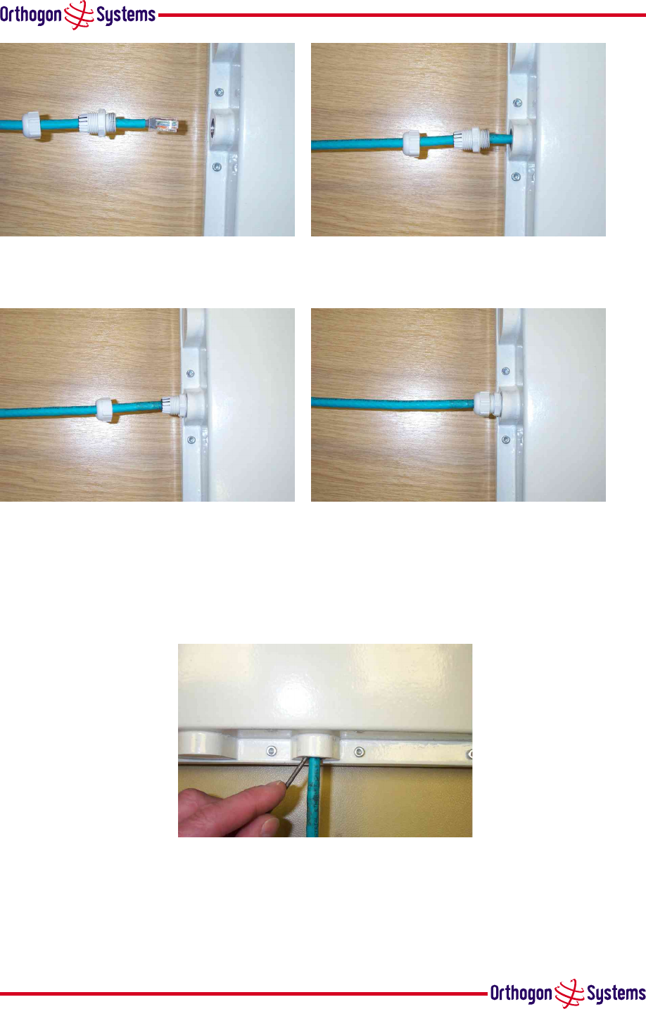
Step 1: Assemble the cable
as described in 5.5.2.1 above
Step 2: Insert the RJ45 connector making
sure that the locking tab snaps home
Step 3: Screw in the body of the weather
proofing gland and tighten to ?? Nm
Step 4: Screw on the clamping
nut and tighten to ?? Nm
Should it be necessary to disconnect the IDU to ODU cable at the ODU this can be achieved by re-
moving the weather proofing gland and depressing the RJ45 locking tab with a small screwdriver
as shown below:
Step 1: Disconnecting the ODU
Warning: Ensure that power is removed from the system at the IDU to prevent damage to the
ODU whilst breaking the connection.

29
5.5.2.3 Routing the Cable
After connecting the cable to the ODU it can be routed and secured using standard cable routing
and securing techniques. When the cable is in place it can then be cut to the desired length at the
IDU prior to connection to the IDU.
5.5.2.4 Fitting A Surge Arrestor
If you have opted to fit a Surge Arrestor, this should be installed by following the manufacturers
instruction.
5.5.2.5 Grounding The Installation
The Gemini 5810 Outdoor unit must be properly grounded to protect against power surges. It is
the user’s responsibility to install the equipment in accordance with Section 810 of the National
Electric Code, ANSI/NFPA No.70-1984 or Section 54 of the Canadian Electrical Code. These
codes describe correct installation procedures for grounding the outdoor unit, mast, lead-in wire
and discharge unit, size of grounding conductors and connection requirements for grounding
electrodes. It is recommended that installation of the outdoor unit be contracted to a professional
installer.
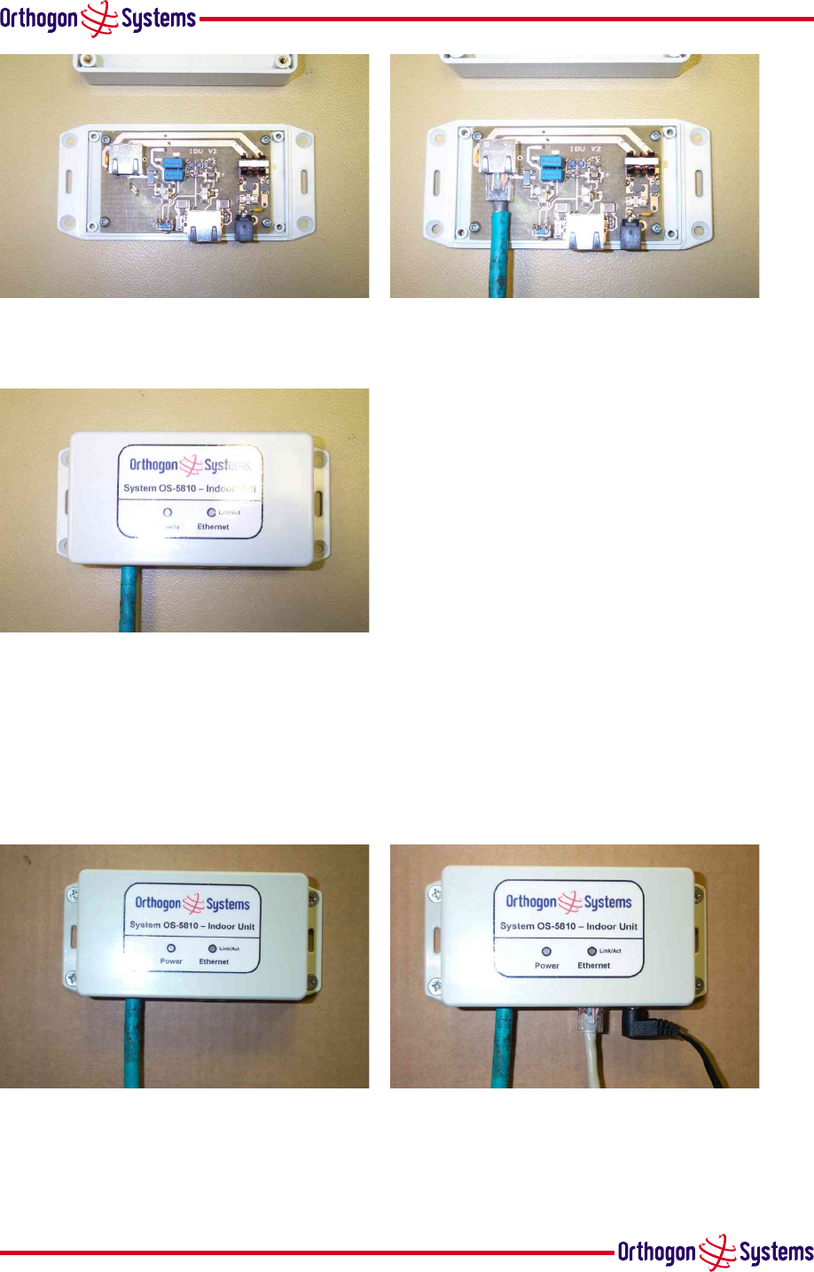
5.5.2.6 Making the Connection At The IDU
The ODU is connected to the IDU by means of a concealed RJ45 connector. The RJ45 connection
has been placed inside the IDU to prevent the user inadvertently plugging other equipment into
the ODU RJ45 socket.
Warning: Plugging other equipment into the ODU RJ45 socket may damage the equipment due
to the non-standard Power-over-Ethernet techniques employed.
30
Step 1: Remove the cover by
removing the four cover fixing screws.
Step 2: Plug in the ODU to IDU
cable ensuring that it snaps home.
Step 3: Replace the cover
5.5.3 Mounting The IDU
This step is optional. Orthogon Systems recommends that you mount the IDU on a wall or other
suitable mounting surface. This prevents the unit from being knocked or kicked and can help
maintain link availability.
Step 1: Fix the IDU to the
wall using the lugs provided.
Step 2: Connect the DC
power and LAN connection

31
5.5.4 Powering Up
Prior to powering up the OS-Gemini, a computer with web browsing capabilities should be
configured with an IP address of 10.10.10.n and subnet mask of 255.0.0.0 where n is any value
between 1 and 254 but excluding 10. If the default address of the unit 10.10.10.10 clashes with
an address you are already using on your LAN, or you are not sure, you should set up an isolated
LAN. As the LAN connection presented at the IDU has a default configuration as a hub/switch
(and auto-sensing MDI/MDI-X cross over is employed).connection can be made directly to the
computer using a standard CAT 5 patch cable.
The unit to be configured can now be powered up and accessed using the default URL http://10.10.10.10/.
If operating both OS-Gemini units on the same LAN for configuration purposes do not power up
both units at the same time as this will result in the use of a duplicate IP address.
Tip: The ping command is sometimes useful to determine connectivity between the unit being
configured and the computer.
Each unit can now be configured with an operational IP address within your LANsIP address
range using the IP configuration web page described in section 6.3.2 “Install Pages” figure 20.
Tip: Should you lose track of the IP address during this process, the unit can be reset to the
factory settings of 10.10.10.10 by following the reset procedure described in section 1.3.2
“The Indoor Unit (IDU)”.
5.5.5 Aligning the ODUs
The following is a description of the steps taken to establish a radio link between the two units
forming the bridge and align the units for the best signal strength.
Step 1: Mount the first unit in its target location.
Step 2: Power up the unit.
Step 3: Connect to the unit using a web browser.
Step 4: Using the installation web pages described in section 6.3.2 “Install Pages” configure the
unit to be the Master.
Step 5: Cycle the power on the Master unit to reset the unit and enable as Master.
Step 6: Point the Master unit in the direction of the other (Slave) units target mounting position.
Step 7: Tighten the units mounting bracket.
Step 8: Mount the second unit in its target location.
Step 9: Power up the unit.
Step 10: Connect to the unit using a web browser.
Step 11: Using the installation web pages described in section 6.3.2 “Install Pages” configure the
unit to be the Slave.

32
Step 12: Cycle the power on the Slave unit to reset the unit and enable it as Slave.
Step 13: Align the Slave unit using the audible tone. (The higher the frequency of the tone, the
better the signal).
Step 14: When the best signal strength has been found. Hold the unit steady (preferably lock the
unit’s mounting bracket) for 10 seconds for the installation process to complete. The completion
of the installation process is indicated by the audible tone being turned off.
Step 15: If not already done, tighten the unitÕs mounting bracket without moving the unit from
its aligned position.
The following steps are optional depending on the reliability of the link and the confidence
of the installer that the link has the desired fade margin to work reliably throughout the year.
Interference to other users of the band may also need to be considered when deciding whether
to align the other (Master) end of the link. The following is basically a repeat of the above steps
with the Master/Slave status of the units swapped.
Step 16: Using the installation web pages described in section 6.3.2 “Install Pages” configure the
second unit to be the Master.
Step 17: Cycle the power on the new Master unit.
Step 18: Using the installation web pages described in section 6.3.2 “Install Pages” configure the
first unit to be the Slave.
Step 19: Cycle the power on the new Slave unit.
Step 20: Align the new Slave unit using the audible tone. (The higher the tone, the better the
signal). When the best signal strength has been found.
Step 21: Hold the unit steady (preferably lock the unit’s mounting bracket) for 10 seconds for
the installation process to complete. The completion of the installation process is indicated by
the audible tone being turned off.
Step 22: If not already done, tighten the unit’s mounting bracket without moving the unit from
its aligned position.
33
6 Web Page Reference
This section contains an explanation and usage guide for each of the built-in management web
pages. Where the user enters data into a field it is necessary to press the appropriate update
button to write the new configuration value to unit’s configuration memory.
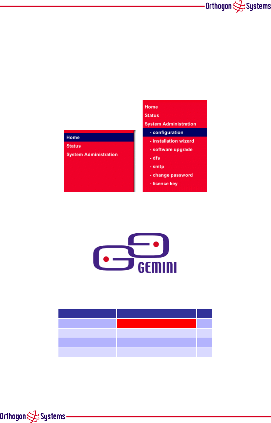
The small and full menus are shown in figure 14. The full menu is only available to the system
administrator after logging in. The login panel is automatically presented when the configuration
menu is selected for the first time.
Figure 14 Web page menus
6.1 Home Page
System Summary
Attributes Value Units
Wireless Link Status Down
Link Name
Elapsed Time Indicator 0 Days 08:26:40
Wireless Link Availability 0.0000 %
Figure 15 Home Page
This page is displayed when initial connection is made to the unit. Navigation to all the unit’s
management functions is via the menu items on the left hand side. This page also displays status
items indicating the current link status, link up time and link availability metric.

34
6.2 Systems Status Page
This page displays the current system status. This page will automatically refresh after a user
defined refresh period. A field is provided to enter the required refresh period. Buttons are
provided to update the refresh period and reset the displayed counters. Refresh can be forced by
using the browsers refresh button.
Figure 16 Status Page
In the section“Equipment” there are various status displayed. The “Country Variant” is depen-
dant upon the software load. The “Link Name” and “Link Location” are attributes which can
be set using the “System Administration” page. Software and Hardware version numbers are
provided as well as the “Elapsed Time Indicator” providing the run time since the last reset.
In the section “Ethernet / Internet” the status of the Ethernet link is provided. The IP address is
that of the web pages and is set on installation or by use of the “System Configuration”. The
SMTP settings can be adjusted on the SMTP page. The page can be automatically refreshed by
the use of the “Refresh this page every...” box and pressing the “Update Page Refresh Period”
button.
The section on “Wireless” gives the status of the wireless link. The “Target Modulation Mode”,
Transmit Power Control and Maximum Transmit Power are controlled on the “System Configu-
ration” Page. Transmit and Receive Power, Vector error and Link Loss are displayed Maximum,
Mean and Minimum for the last complete hour. The DFS status is given along with the Active
and available channels. Finally the Radio Range is given and the average bit rate.
35
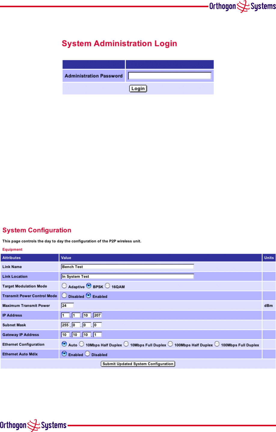
6.3 System Administration Page
Figure 17 System Administration Page
The system administration pages are password protected. On first activation the user will be
presented with the above page prompting them to change the system administration home page.
Once the password has been set the system administration pages will only be available after the
user has entered the correct password. All system configuration pages are accessed via the main,
password protected, system administration page.
6.3.1 System Configuration Page
This page is used to enter data about the link. This data is used by the alert and management
functionality to identify the link and equipment for status and fault reporting purposes. You may
also set the maximum transmit power and IP address and subnet mask for Web Access. Note that
the default IP address if not set is 10.10.10.10.
Figure 18 Configuration Page
Note: At this point you will loose connection to the unit. You now have to reconnect to the unit
using the address just set.
36
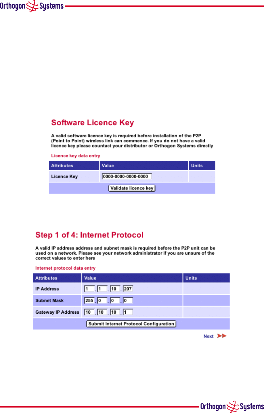
6.3.2 Install Pages
These pages are used during system installation. There follows a description of the install pages
along with their use during the installation process. The actual installation process is described in
section 5.5.5 “Aligning the ODUs” above. Step 1 figure 19 will automatically invoke on starting
the installation wizard if there is no valid license key stored. The OS-Gemini operational soft-
ware requires a license key to enable the wireless bridging capability. A license key is supplied
with each unit and can be found in the envelope marked “License Key” pack along with the units
documentation. If subsequently the license key has been mislaid, you can apply for a license
key on line at License Application. Your license key should be entered as shown above and the
“Submit updated values” button pressed.
Figure 19 Licence key entry
Step 2 figure 20 is used to set the IP addresses.
Figure 20 Installation page 1 — Internet Protocol Settings
Step 3 figure 21 is used to set the MAC Address of the peer unit that will be at the other end
of the wireless link. The serial number is the hexadecimal representation of the serial number
written into the last 3 bytes of the units MAC address. At this point it is necessary to decide which
end will be master. The Master unit is the controlling unit with respect to the radio link and its
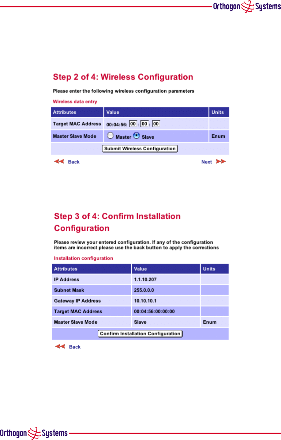
37
maintenance. Master transmits until the link is made, Slave listens for its peer and only transmits
when the peer has been identified. figure 21 shows;
•Unit serial number is in Hex. 106 = MAC address 00:04:56:00:01:06
•Unit acting as Master.
Figure 21 Installation page 2 — Wireless Configuration
Step 4 figure 22 is for confirming and committing to non-volatile memory the settings just en-
tered.
Figure 22 Installation page 3 — Confirm Installation
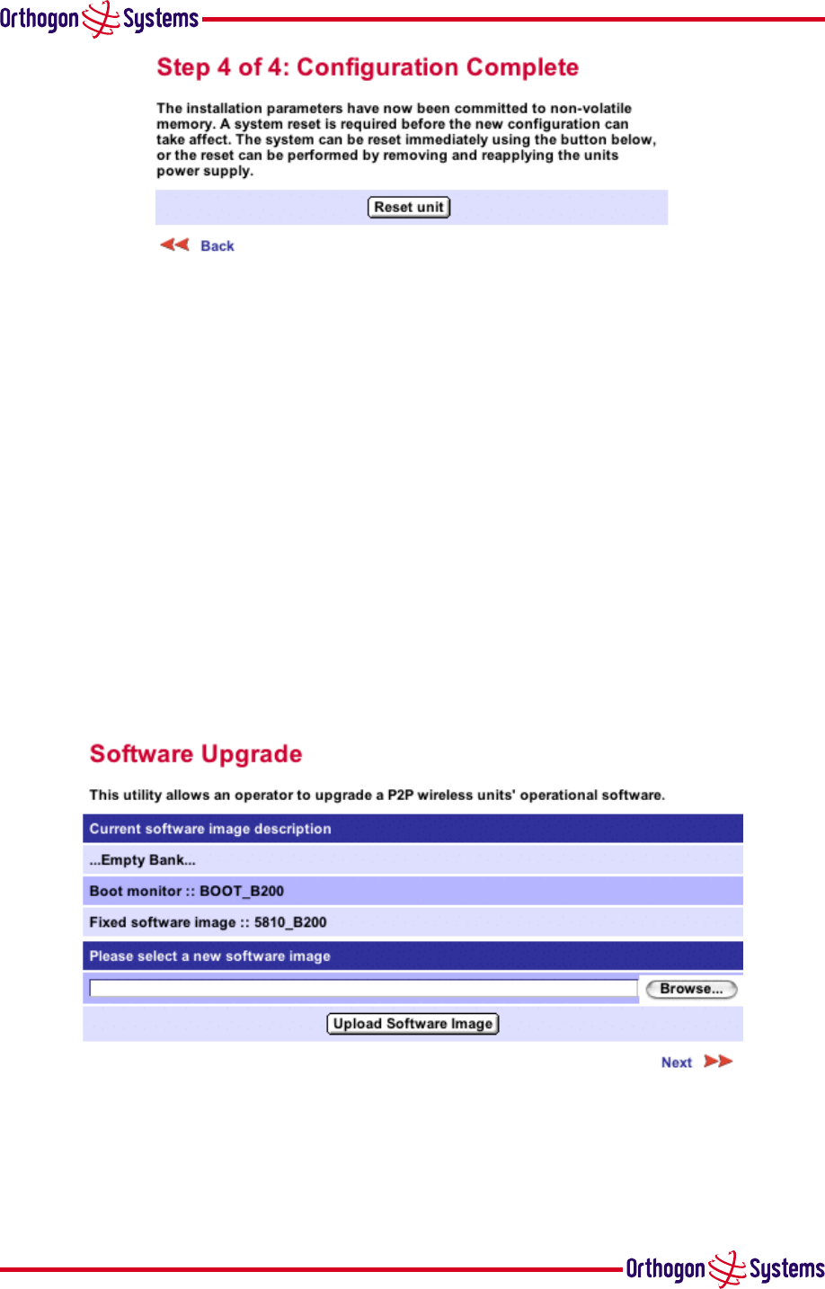
Step 5 figure 23 is used for using the settings previously entered.
If the unit has been configured as the Master, the unit will restart with the transmitter transmitting
on a suitable channel having executed a scan for possible “Jamming” signals. The unit will
remain in this state until the matching Slave unit has completed its alignment and registration
process when the unit will take over control of the radio link and start the DFS functionality.
38
Figure 23 Installation page
4 — Configuration Complete
If the unit has been configured as the Slave, the unit will restart with the audible installation tone
turned on at the ODU. The unit will remain in this state until the signal from the corresponding
Master unit has been found, and the alignment and registration stages completed. The alignment
stage is taken to be complete when the signal received from the master does not vary for 10
seconds. i.e. the installer is no longer moving the unit. Registration will occur as soon as the
alignment stage is complete. Completion of the registration process is marked by the audible
installation tone being switch off. The unit will now enter operation as the Slave unit taking its
operational parameters and commands from the Master unit.
6.3.3 Software Upgrade Pages
These pages are used to update a unit’s operational software. The software image to be upload-
ed should be downloaded to local storage from the Orthogon Systems support website www.
orthogonsystems.com/support/download prior to using this utility.
Figure 24 Software upgrade
The first step is to use the “Browse” button to locate the software image previously downloaded
to local storage from the Orthogon Systems support website. Once the image is located the user
should press the “Upload image to wireless unit” button to start the software upgrade process.
39
The software image will now be downloaded to the unit where it will be stored in RAM until it is
committed to the units flash memory. This download should only take a few seconds.
NEW SCREEN SHOT The unit being upgraded will now display its current flash memory status.
The user should ensure that he is happy to proceed before pressing the “Continue” button. The
user has the option to bail out at this point by pressing the “Abort“ button. On pressing the
“Continue” button the user should ensure that the power is not cycled, or any other functionality
accessed, until the next screen is displayed. This process can take up to 30 seconds.
NEW SCREEN SHOT When the software image has been written to flash memory the above
screen will be displayed showing the status of the software download. If this screen is not dis-
played after 30 seconds this could indicate a problem with the memory update process. The user
should now power cycle the unit to start using the new software image. The units boot software
will automatically determine the health of the newly downloaded software image. If there are
any problems the boot code will revert to a protected operational software image installed during
manufacturing.
After the power cycle the user should check that the required software image is loaded and
running by re-entering the Upgrade page where the software bank status will be displayed.
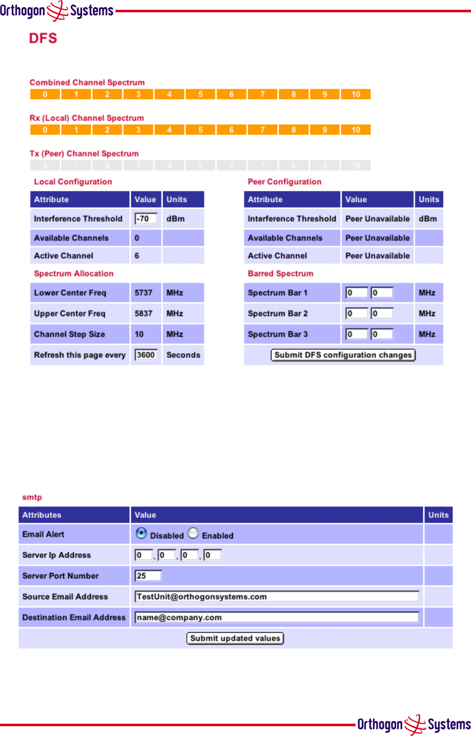
6.3.4 DFS Pages
This page is used to control and display information about the units DFS functionality. The only
user configurable attributes are the page refresh period and channel usage.
The three upper displays show the combined and individual channel status. The colours denote
the status of each of the channels according to the following table.
Yellow Active The channel is being used for connection
Green Available The channel is available for use
Orange Interference The channel has interference above the interference threshold
Red Radar The channel has a very high level of interference
Black Barred The channel has been barred from use
In the “Local Configuration” the interference threshold can be set. A normal value for this is
about -80 dBm. When the interference is above this level the display will change to orange. The
available channels are those below the interference threshold which are not barred. The active
channel number is also displayed as a number.
In the “Peer Configuration” section the configuration of the other end of the link is given.
In the “Spectrum Allocation” section the centre channel frequency range is given and the channel
step size.
In the Barred Channel section the ability is given to not allow certain channels to be used. This is
for barring the frequency range of the centre frequency of the channel. There are three separate
ranges that can be chosen giving many possibilities.
40
Figure 25 DFS page
6.3.5 SMTP Configuration Page
This page is used to configure the email alert functionality. The facility can be enabled, the
server address and port number entered. The source and destination email addresses can also be
entered.
Figure 26 SMTP page
41
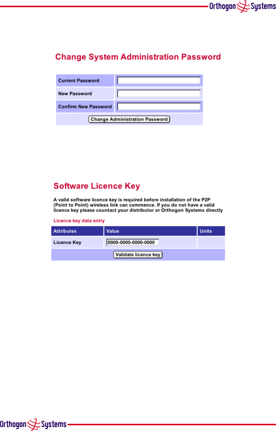
6.3.6 Change System Administration Password
This is the screen to change the password for the system administration.
Figure 27 Password page
6.3.7 Software License Key
This page is for the entry of the Software License Key if necessary.
Figure 28 License page
42
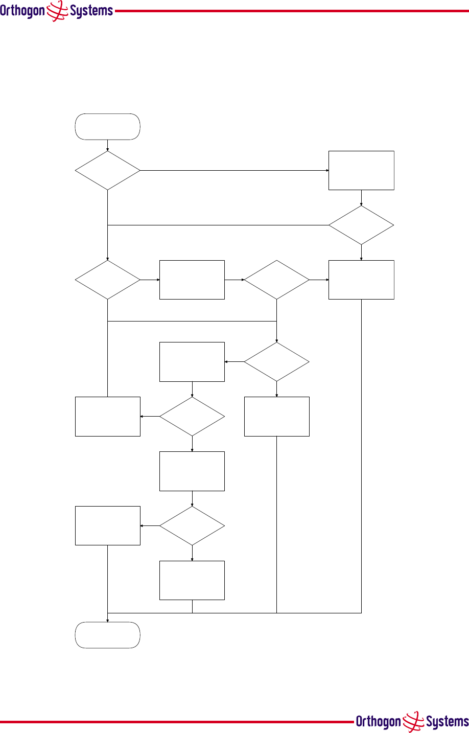
7 Fault Finding
Before contacting your re-seller/distributor or returning the unit to the manufacturer you should
follow the following fault finding guide figure 29:
Start
Power
indicator
lit
Power
indicator
lit
Green
indicator
activity
Yellow
indicator
activity
Other end of
link powered
Green
indicator
activity
Signal path OK
End
Check cabling
and
mains supply
No Ethernet Link
Check Connections
Return unit to
Manufacturer
No radio link
Check other end
of link
Apply power to
other end of link
Unit functioning
OK check further
back in network
Check signal path
Re-install link
Contact your re-
seller or distributor
for assistance
No
Yes
Yes
No
No
Yes
No
Yes
No
Yes
No
Yes
No
Yes
Figure 29 Fault Finding Guide
43
8 Specifications
8.1 System Specification
Radio Technology i-OFDM
RF Band USA 5.725 – 5.850 GHz (ISM)
Channel Selection By Dynamic Frequency Control
Dynamic Frequency
Control
Initial capture 2 sec., Out of service on interference 100 ms.
Channel size 10 MHz
Channel selection Automatic detection on start-up and continually adapting
Tx power @ Antenna port Up to 12 dBm/MHz with Transmit Power Control at the
antenna port
Transmit Power Control Loop bandwidth 1 Hz, Range 30dB typical
Rx sensitivity @ Rx input -93 dBm for BPSK
-83 dBm for 16 QAM
Receiver Noise Figure Typically 6 dB or less
Antenna Type Integrated dual polar flat plate antenna
Antenna Gain 23dBi per polarisation
Max Path loss US 164dB
Modulation Dynamically adapting between 16QAM and BPSK
Duplex Scheme TDD, Ratio 50:50, Switch Rate 500Hz
Data Rate @ Air Interface 16 Mbps (16QAM) and 4 Mbps (BPSK)
Range 25 miles (40km) optical line-of-sight
6 miles (10km) non-line-of-sight
Over the air encryption Proprietary scrambling mechanism
Weather sensitivity None
Ethernet Bridging
Protocol IEEE802.1; IEEE802.1p; IEEE802.3 compatible
Interface 10/100BaseT (RJ-45), Supports MDI/MDIX Auto Crossover
Data Rate @ Ethernet 14.2 Mbps (16QAM) and 3.5 Mbps (BPSK)
44
Management Embedded web server for direct management
Configuration DHCP client (default IP address:10.10.10.10)
Status Indicators Power status
Radio Link status
Ethernet Link Status
Data activity
Alarms Via configurable email alerts
Physical Integrated outdoor unit with indoor PSU
Dimensions Width 15.75” (400mm), Height 15.75” (400mm), Depth 3.94”
(100mm)
Weight 12.1 lbs (5.5 Kg) including bracket
Wind loading 75 Mph operating, 111 Mph survival (Class III Hurricane)
Power Supply Separate power supply unit (included)
Power source 90 – 264 VAC, 50 – 60 Hz
Power consumption 25 W mean (85 BTU/Hr)
Environmental
Operating temperature ODU -40°F (-40°C) to 131°F (50°C)
IDU 32°F (0°C) to 104°F (40°C)
Protection IP65
8.2 Safety Compliance
Region Specification
USA UL 60950
Canada CSA C22.2 No. 60950
Table 1 — OS-Gemini Safety Compliance
8.3 EMC Emissions Compliance
Region Specification
USA FCC Part 15 Class B
Table 2 — OS-Gemini EMC Emissions Compliance
45
8.4 EMC Immunity Compliance
Top-level specification ETSI 301-489.
Specification Comment
EN 55082-1 Generic EMC and EMI requirements for
Europe
EN 61000-4-2: 1995 Electro Static Discharge (ESD),
Class 2, 8 kV air, 4 kV contact discharge
EN 61000-4-3: 1995 ENV50140: 1993 (radiated
immunity) 3 V/m
EN 61000-4-4: 1995 (Bursts/Transients), Class 4, 4
kV level (power lines AC & DC)
Signal lines @ 0.5 kV open circuit
voltage.
EN 61000-4-6: 1996 (Injected RF), power line, Class
3 @ 10 V/m
Signal lines, Class 3 @ 3 V RMS
unmodulated.
Table 3 — OS-Gemini EMC Immunity Compliance
8.5 Radio Certifications (type approvals)
Region Reference
USA FCC Part 15 Subpart C (15.247)
Table 4 — OS-Gemini Radio Certification
8.6 Environmental Specifications
General statement in here
46
Environmental
Specifications
Temperature -40°C to +50°C plus the effects of solar radiation
Vibration and Shock ETS 300 019-1-4, Class 4.1 E
Altitude ETS 300 019-1-4, Class 4.1 E
Wind Loading ETS 300 019-1-4, Class 4.1 E, In addition, the mounting
hardware ensures that in all wind strengths up to 75mph, the
alignment of the ODU will be within 2°of the nominal setting.
In higher wind strengths up to 111mph, the ODU will survive
and return to its original alignment after the exposure.
Humidity ETS 300 019-1-4, Class 4.1 E
Wind-driven Rain ETS 300 019-1-4, Class 4.1 E
Biological Conditions ETS 300 019-1-4, Class 4.1 E
Chemically Active
Substances
ETS 300 019-1-4, Class 4.1 E, MIL-STD-810E, Method 509,
Proc 1
UV Exposure 10-year operational life (UL746C test evidence)
Transportation ETS 300 019-1-2
Storage ETS 300 019-1-1, Class 1.2
Table 5 — OS-Gemini Environmental Specifications
8.7 System Connections
8.7.1 ODU to IDU Connection
Figure 13 - ODU to IDU Connection Diagram
8.7.2 Network Connection
Figure 14 - Network Connection Diagram (Hub/Switch presentation)
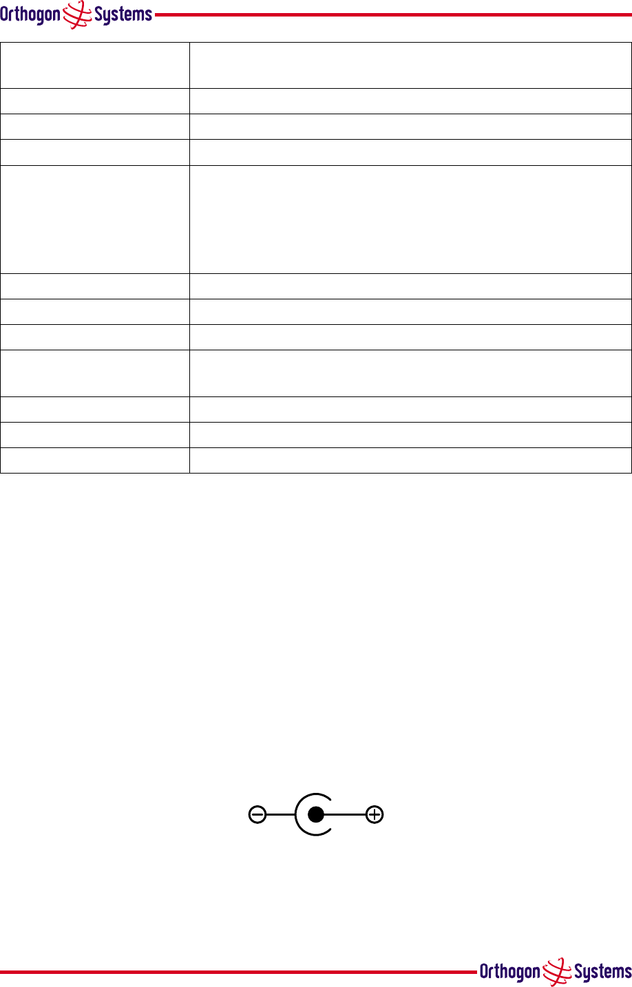
8.7.3 Power Connection
The IDU power connection is via a standard DC power socket.
48V DC
Figure 30 DC
Connection Diagram


48
9 Lightning Protection
The idea of lightning protection is to protect structures, equipment and people against lightning
by conducting the lightning current to ground via a separate preferential solid path and by reduc-
ing the electromagnetic field.
The following should be treated as a guide only. Full details of lightning protection methods
and requirements can be found in the international standards IEC 61024-1 and IEC 61312-1, the
National Electric Code ANSI/NFPA No. 70-1984 or section 54 of the Canadian Electric Code.
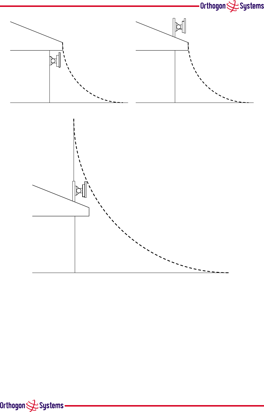
The installation of the ODU can be classified into two different lightning protection zones.
•Zone A — In this zone a direct hit is possible.
•Zone B — In this zone a direct hit is not possible, but the unattenuated electromagnetic field
is present.
The next diagrams show this zoning pictorially:
Equipment mounted in Zone A should be capable of carrying the full lightning current. Mount-
ing of the ODU in Zone A is not recommended. Mounting in Zone A should only be carried
out observing the rules governing installations in Zone A. Failure to do so may put structures,
equipment and life at risk.
Equipment mounted in Zone B should be grounded using grounding wire of at least 10 AWG.
This grounding wire should be connected to a grounding rod or the building grounding system
before entry in to building.
The OS-Gemini ODU grounding point can be found on the bottom of the unit. The OS-Gemini
is supplied with the appropriate grounding lug for attachment to the ODU.
49
Zone A
Zone B
Zone A
Zone B
ODU mounted inside Zone B ODU mounted in Zone A
Zone A
Zone B
]
ODU mounted inside Zone B
Figure 31 ODU Mounting Positions

50
10 FAQs
This section contains a number of Frequently Asked Questions. This list is not exhaustive.
Further and more up to date FAQs may be found in the Orthogon Systems website at: http:
//www.orthogonsystems.com/support/FAQ
Q: The 100BaseT Ethernet specification specifies a maximum length of 100m. Why am I re-
stricted to 60m of cable between the IDU and ODU?
A: The 60m restriction is a result of the voltage drop experience using CAT 5 cable. The 100m
maximum length still applies between the ODU and connected equipment.
Q: Can I source and use my own PoE adaptor with the OS-Gemini?
A: No. The OS-Gemini uses a non-standard PoE configuration. Failure to use the Orthogon
Systems supplied IDU and in-line power supply could result in equipment damage and present
potential safety problems.
Q: ?????
A: ?????

51
11 Glossary
BPSK Binary Phase Shift Keying
CAI Computer Aided Instruction
DC Direct Current
DFS Dynamic Frequency Selection
ETSI European Telecommunications
Standards Institute
FAQ Frequently Asked Question
HQ Headquarters
HTTP Hypertext Transfer Protocol
ID Identity
IDU Indoor Unit
IEEE Institute of Electrical and Elec-
tronic Engineers
IP Internet Protocol
ISM Industrial Scientific and Medical
ITU International Telecommunications
Union
LAN Local Area Network
MAC Medium Access Control Layer
NLOS non--Line--of--Sight
ODU Outdoor Unit
OFDM Orthogonal Frequency Division
Multiplex
POE Power-over-Ethernet
QAM Quadrature Amplitude Modula-
tion
RAM Random Access Memory
SMTP Simple Mail Transfer Protocol
STC Space Time Coding
STP Shielded Twisted Pair
TFTP Trivial File Transfer Protocol
TPC Transmit Power Control
URL Universal Resource Location
USA United States of America
UTP Unshielded Twisted Pair
UV Ultraviolet
VLAN Virtual Local Area Network


Orthogon Systems, Linhay Business Park, Eastern Road, Ashburton, Devon TQ13 7UP
Telephone: +44 (0)1364 655500 Fax: +44 (0)1364 654625
www.orthogonsystems.com