Cambium Networks 89FT0023 cnPilot Outdoor E500 User Manual
Cambium Networks Inc. cnPilot Outdoor E500 Users Manual
Users Manual
cnPilot™ E500
All E500 Models
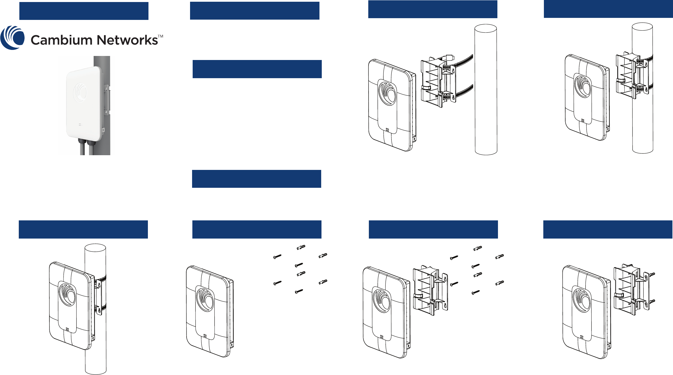
Quick Start Guide Introduction
This sheet details assembly and
installation of cnPilot E500.
Package Contents
Step 1 (Pole Mount) Step 2 (Pole Mount)
Tools Required
- Phillips screwdriver (Wall mount)
- Flat-head screwdriver (Pole mount)
Step 3 (Pole Mount) Wall Mount (No Bracket) Step 1 (Wall Mount w/bracket) Step 2 (Wall Mount w/bracket)
Turn sheet over to continue.
Insert the mounting straps through the
mounting bracket.
Tighten the mounting straps around the
pole using a at-head screwdriver.
Attach the cnPilot E500 to the mounting
bracket.
Attach the mounting bracket to the screws.
Insert the wall anchors into the wall using
the mounting bracket as a template and
insert the screws. Attach the cnPilot E500 to
the screws.
Insert the wall anchors into the wall using
the mounting bracket as a template and
insert the screws.
- E500 access point - x1
- E500 pole/wall mount bracket - x1
- 56V/30W gigabit passive PoE
power injector - x1
- Wall-mounting screw kit - x1
- RJ45 IP67 gland connectors - x2
- AC power cord (not for RoW SKU) - x1
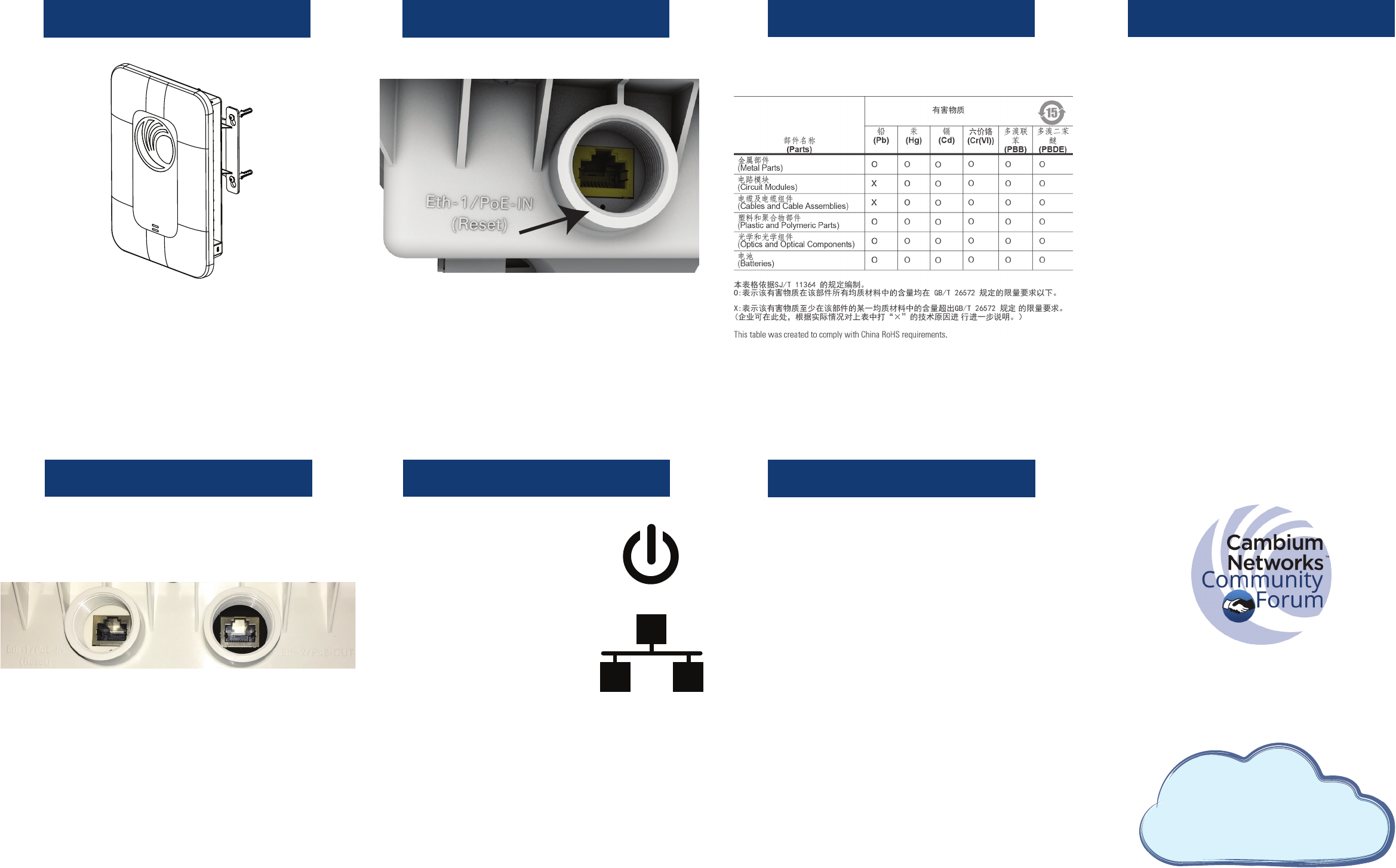
Step 3 (Wall Mount w/bracket) Reset Procedure RoHS Compliance WEEE Statement
Powering LEDs Default Configuration
Join the conversation
community.cambiumnetworks.com
To reset cnPilot E500:
- Press the reset button. The cnPilot E500 will
reboot.
- Hold the button for 10 seconds. The cnPilot
E500 conguration will be reset to factory
default settings.
Attach the cnPilot E500 to the mounting
bracket.
To power cnPilot E500:
- Connect the provided 56V/30W gigabit
passive PoE power injector provided to the
Eth1 port.
To power another device
using cnPilot E500:
- Connect the device to the Eth2 port .
- Congure cnPilot E500 to output power
on the Eth2 port by using the webpage
management interface.
System LED
When amber the system is powering up,
and when green the system is fully powered.
Network LED
When amber, the cnPilot E500 is not con-
nected to cnMaestro, and when green,
cnPilot E500 is connected to cnMaestro.
Default IP address:
- Received via DHCP.
- cnPilot E500 will use a default static IP
address of 192.168.0.1 if there is no DHCP
server.
Default login information:
- Username: admin
- Password: admin
Management protocols enabled by default:
- HTTP, HTTPS (webpage management
interface access), SSH (CLI management
interface access).
cnMaestro
Ready
™
cnMaestro
Ready
™
cnPilot E500 is cnMaestro ready
Cambium Networks is committed to meeting the
requirements of the European Union (EU) Waste Electri-
cal and Electronic Equipment (WEEE) Directive. This
Directive requires producers of electrical and electronic
equipment to nance the takeback, for reuse or recy-
cling, of their products placed on the EU market after
August 13, 2005. Cambium Networks products that are
within the scope of the Directive are labelled with a
crossed-out "wheelie-bin" symbol, as required by the
Directive. It indicates that the product was placed on the
market after August 13, 2005 and that end users should
segregate the product from other waste at end-of- life.
The WEEE Directive is being implemented in each of the
27 EU countries through national legislation. Norway
and Switzerland have also implemented similar pieces of
legislation. As a result, the detailed requirements vary
considerably throughout the EU, and the Cambium
Networks WEEE compliance approach varies among
countries. In each country aected by the WEEE
legislation.
Eth1 Eth2
cambiumnetworks.com/support
System LED
Network LED
FCC Statement:
Federal Communication Commission Interference Statement
This equipment has been tested and found to comply with the limits for a Class B digital device, pursuant to Part 15 of the FCC Rules. These limits
are designed to provide reasonable protection against harmful interference in a residential installation. This equipment generates, uses and can
radiate radio frequency energy and, if not installed and used in accordance with the instructions, may cause harmful interference to radio
communications. However, there is no guarantee that interference will not occur in a particular installation. If this equipment does cause harmful
interference to radio or television reception, which can be determined by turning the equipment off and on, the user is encouraged to try to correct the
interference by one of the following measures:
● Reorient or relocate the receiving antenna.
● Increase the separation between the equipment and receiver.
● Connect the equipment into an outlet on a circuit different from that to which the receiver is connected.
● Consult the dealer or an experienced radio/TV technician for help.
FCC Caution: Any changes or modifications not expressly approved by the party responsible
for compliance could void the user’s authority to operate this equipment.
This device complies with Part 15 of the FCC Rules. Operation is subject to the following two conditions: (1) This device may not cause harmful
interference, and (2) this device must accept any interference received, including interference that may cause undesired operation.
For product available in the USA/Canada market, only channel 1~11 can be operated. Selection of other channels is not possible.
IMPORTANT NOTE:
FCC Radiation Exposure Statement:
This equipment complies with FCC radiation exposure limits set forth for an uncontrolled environment. This equipment should be installed and
operated with minimum distance 20 cm between the radiator & your body.