Cambium Networks 89FT0035 cnPilot E410 Indoor User Manual e410 QSG 25rd May
Cambium Networks Inc. cnPilot E410 Indoor e410 QSG 25rd May
User Manual
Model: e410
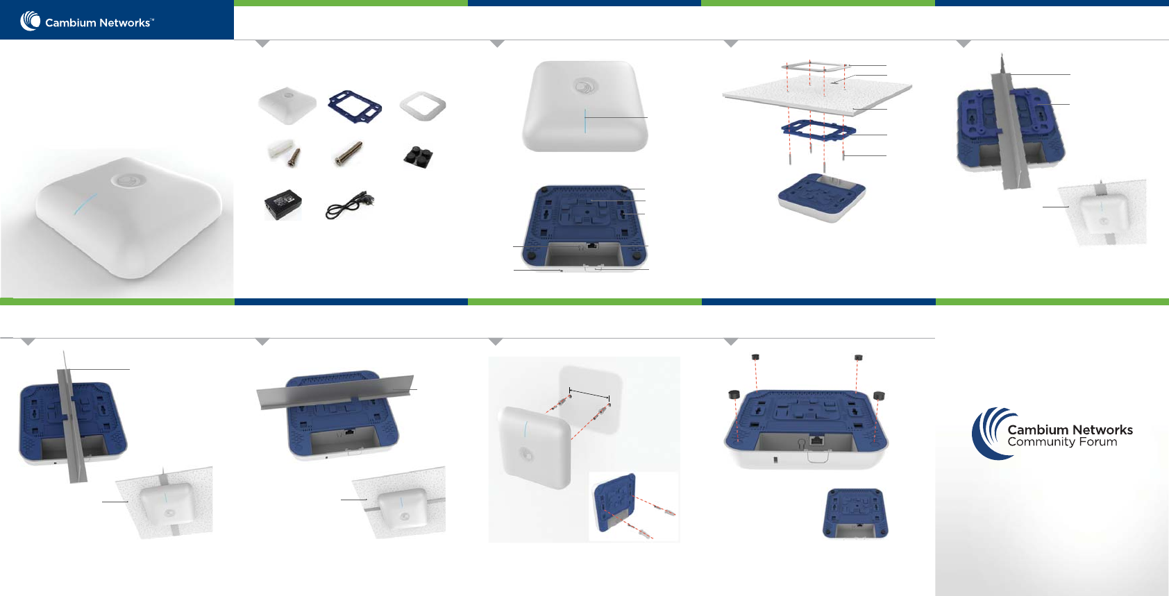
The e410 can be mounted to a 14mm width T-bar rail
using the clips built into the underside of the unit.
The e410 can be mounted on any surface by attaching
the rubber feet to the underside of the unit.
24mm T-Bar Rail Mounting Wall Mounting Rubber feet Assembly
Introduction
The guide provides a quick installation process.
Tool Requirements
38mm T-Bar Rail Mounting
The e410 mounts to a ceiling tile and allows for the
ethernet cable to be hidden by routing through a hole in
the ceiling tile.
• Philips Screwdriver
Ceiling Tile Mounting
community.cambiumnetworks.com
JOIN THE CONVERSATION
Product Overview
Package Contents
e410 Access Point
Ceiling Mounting Screws
(Qty. 4)
POE Injector*
Rubber Foot
(Qty. 4)
The e410 mounts to any wall by using two screws with
corresponding wall anchors.
Ceiling Mounting Bracket
Wall Mounting Kit
(Qty. 2)
Power Cord*
cnPilotTM (410,QGRRU
802.11ac Wave2 Indoor
Access Point
Quick Start Guide Mounting Plate
Tools Required
Multi-color LED
Top View
Mounting Plate
Ceiling Tile
Mounting Bracket
Screws x4
Exploded View
38mm wide T-bar rail
Mounting Bracket
Ceiling Tile
The e410 can be mounted to a 24mm width T-bar rail
using the clips built into the underside of the unit.
24mm wide T-bar rail
Ceiling Tile
14mm T-Bar Rail Mounting
Ceiling Tile
14mm wide
T-bar rail
* Only available for certain ordering SKUs
Desk Mount Foot
T-bar Mount Holder
Reset Button LAN Port
Removable Clip
Wall Mount Anchor
Bottom View
Kensington
Lock Slot
Cable Route Hole
The e410 is secured to a 38mm ceiling T-bar rail by using
the ceiling mount bracket.
118mm
AP Management
Safety Notice FCC Compliance RoHS/WEEE Compliance
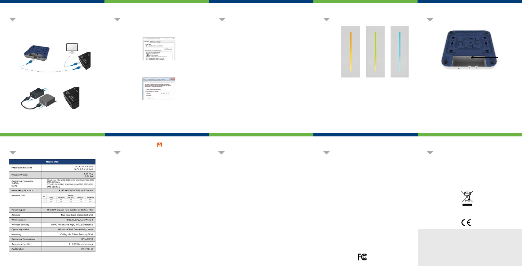
Configure Management PC
Specifications
Hardware Overview
Hardware Overview
Powering Up
Online Resources
User Guide and software downloads:
https://support.cambiumnetworks.com/files/e410/
Support:
http://www.cambiumnetworks.com/support/
Contact us:
http://www.cambiumnetworks.com/support/contact-support/
Caring for the Environment: RoHS/WEEE
European Directive 2002/96/EC requires that the equipment bearing this symbol on
the product and/or its packaging must not be disposed of with unsorted municipal
waste. The symbol indicates that this product should be disposed of separately from
regular household waste streams. It is your responsibility to dispose of this and
other electric and electronic equipment via designated collection facilities
appointed by the government or local authorities. Correct disposal and recycling will
help prevent potential negative consequences to the environment and human
health. For more detailed information about the disposal of your old equipment,
please contact your local authorities, waste disposal service, or the shop where you
purchased the product.
CE Marking
CE marking on this product represents the product is in compliance with all
directives that are applicable to it.
The cnPilot e410 Access Point supports multiple modes of management:
Standalone: The Access Point can be managed directly from its GUI by
selecting the ‘Configure’ tab on the menu, and setting up a wireless LAN.
Controller : The Access Point can be onboarded to cnMaestro network
controller system, either on-premises or the cloud version at
https://cloud.cambiumnetworks.com.
For management from cloud please ensure the AP has connectivity to
the internet. Connectivity can be verified using tools such as ping from
the ‘Troubleshooting’ tab of the Access Point GUI. Connection status can
be monitored from the AP dashboard.
1.
2.
3.
Select Properties for the Ethernet port. In Windows it is found in
Control Panel > Network and Internet > Network Connections >
Local Area Connection.
IP Address Configuration
Default IP address received via DHCP.
cn Pilot e410 will use a default static IP address of 192.168.0.1, If
there is no DHCP server
Default Login information
- Username: admin
- Password: admin
Changes or modifications not expressly approved by the party responsible for
compliance could void the user’s authority to operate the equipment.
This device complies with Part 15 of the FCC Rules. Operation is subject to the following
two conditions.
1. This device may not cause harmful interference, and
2. This device must accept any interference received, including interference that
may cause undesired operation.
For product available in the USA/Canada market, only channel 1~11 can be operated.
Selection of other channels is not possible.
This device is restricted for indoor use.
IMPORTANT NOTE:
FCC Radiation Exposure Statement:
This equipment complies with FCC radiation exposure limits set forth for an
uncontrolled environment. This equipment should be installed and operated with
minimum distance 20 cm between the radiator & your body.
This equipment has been tested and found to comply with the limits for a Class B digital
device, pursuant to Part 15 of the FCC Rules. These limits are designed to provide
reasonable protection against harmful interference in a residential installation. This
equipment generates, uses and can radiate radio frequency energy and, if not installed
and used in accordance with the instructions, may cause harmful interference to radio
communications. However, there is no guarantee that interference will not occur in a
particular installation. If this equipment does cause harmful interference to radio or
television reception, which can be determined by turning the equipment o and on, the
user is encouraged to try to correct the interference by one of the following measures:
- Reorient or relocate the receiving antenna.
- Increase the separation between the equipment and receiver.
- Connect the equipment into an outlet on a circuit dierent from that to which
the receiver is connected.
- Consult the dealer or an experienced radio/TV technician for help.
IC Statement:
This device complies with Industry Canada license-exempt RSS standard(s). Operation is
subject to the following two conditions: (1) this device may not cause interference, and
(2) this device must accept any interference, including interference that may cause
undesired operation of the device.
Le présent appareil est conforme aux CNR d'Industrie Canada applicables aux appareils
radio exempts de licence. L'exploitation est autorisée aux deux conditions suivantes : (1)
l'appareil ne doit pas produire de brouillage, et (2) l'utilisateur de l'appareil doit accepter
tout brouillage radioélectrique subi, même si le brouillage est susceptible d'en
compromettre le fonctionnement.
Warning:
To prevent loss of life or physical injury, observe the following safety guidelines. In no
event shall Cambium Networks be liable for any injury or damage caused during the
installation of e410 platform. Ensure that only qualified personnel install.
Only use attachments/accessories specified by the manufacturer.
Electrical Safety Information
Compliance with manufacturer’s label for voltage, frequency, and current
requirements. Connecting to a dierent power source than those specified may
result in improper operation, damage to equipment or pose a fire hazard if the
limitations are not followed.
There are no serviceable parts inside this equipment. Service should be
provided only by a qualified service technician.
This equipment is provided with a detachable power cord which has an integral
safety ground wire intended for connection to a grounded safety outlet.
Be aware that the unit surfaces can become very hot to the touch so do not
handle the device when it is running for long periods of time. Turn o power to
the device first for a few minutes and then handle the unit carefully.
Do not substitute the power cord with one that is not the provided
approved type. Never use an adapter plug to connect to a 2-wire outlet
as this will defeat the continuity of the grounding wire.
The equipment requires the use of the ground wire as a part of the safety
certification, modification or misuse can provide a shock hazard that can
result in serious injury or death.
Contact a qualified electrician or the manufacturer if there are questions
about the installation prior to connecting the equipment.
Protective earthing is provided by Listed AC adapter. Building installation
shall provide appropriate short-circuit backup protection.
Protective bonding must be installed in accordance with local national
wiring rules and regulations.
1.
2.
3.
4.
a.
b.
c.
d.
e.
Management Protocols enabled by default –http or https (webpage
management interface access), SSH (CLI management interface access).
Reset Button LAN Port
Bottom View
Reset
The Reset button serves two functions for e410:
- To restart, press and release the Reset button quickly.
- To restore to factory default settings, press and hold the
Reset button for more than 10 seconds.
LAN Port
The Main port is a Gigabit Ethernet port used to connect the power and
should be connected to the LAN and DHCP server.
1.
2.
3.
Connect the Ethernet cable from Eth1/PoE-IN of e410 to the PoE
port of Gigabit Data + Power.
Connect an Ethernet cable from your LAN or Computer to the
Gigabit Data port of the PoE adapter.
Connect the Power Cord to the adapter, and then plug the Power
Cord into a power outlet.
Once powered ON -- Power LED should illuminate continuously on
PoE Adapter.
LED Color Amber Green Blue
Status
Indicator
Access Point is
powering up
and Intitializing
Access Point is
in service.
Access Point is
managed with
cnMaestro or
autopilot.
FCC Compliance
For product available in the USA/Canada market, only channel 1~11 can be operated.
Selection of other channels is not possible.
Pour les produits disponibles aux États-Unis / Canada du marché, seul le canal 1 à 11
peuvent être exploités. Sélection d'autres canaux n'est pas possible.
Dynamic Frequency Selection (DFS) for devices operating in the bands 5250- 5350
MHz, 5470-5600 MHz and 5650-5725 MHz.
Sélection dynamique de fréquences (DFS) pour les dispositifs fonctionnant dans les
bandes 5250-5350 MHz, 5470-5600 MHz et 5650-5725 MHz.
The device for operation in the band 5150–5250 MHz is only for indoor use to reduce the
potential for harmful interference to co-channel mobile satellite systems.
les dispositifs fonctionnant dans la bande 5150-5250 MHz sont réservés uniquement
pour une
utilisation à l’intérieur afin de réduire les risques de brouillage préjudiciable aux
systèmes de satellites mobiles utilisant les mêmes canaux.
For indoor use only.
Pour une utilisation en intérieur uniquement.
IMPORTANT NOTE:
IC Radiation Exposure Statement:
This equipment complies with IC RSS-102 radiation exposure limits set forth for an
uncontrolled environment. This equipment should be installed and operated with
minimum distance 20 cm between the radiator & your body.
Cet équipement est conforme aux limites d'exposition aux rayonnements IC établies
pour un environnement non contrôlé. Cet équipement doit être installé et utilisé avec un
minimum de 20 cm de distance entre la source de rayonnement et votre corps.
This radio transmitter has been approved by FCC to operate with the antenna types
listed below with the maximum permissible gain and required antenna impedance for
each antenna type indicated. Antenna types not included in this list, having a gain
greater than the maximum gain indicated for that type, are strictly prohibited for use
with this device.
Antenna Information: Two dual-band antenna, 0D[Gain 5.24/5.47dBi
&(&WLFN
0+]
)&&,&
0+]