Cambium Networks XD2230 Wireless Access Point User Manual XD2 230 only QIG

Xirrus, Inc. Wireless Access Point XD2 230 only QIG
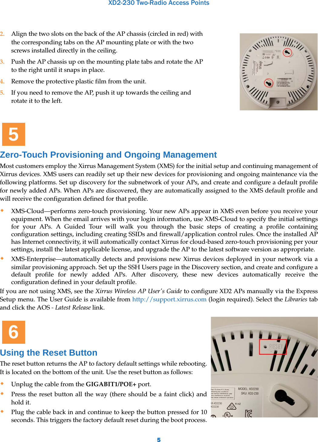
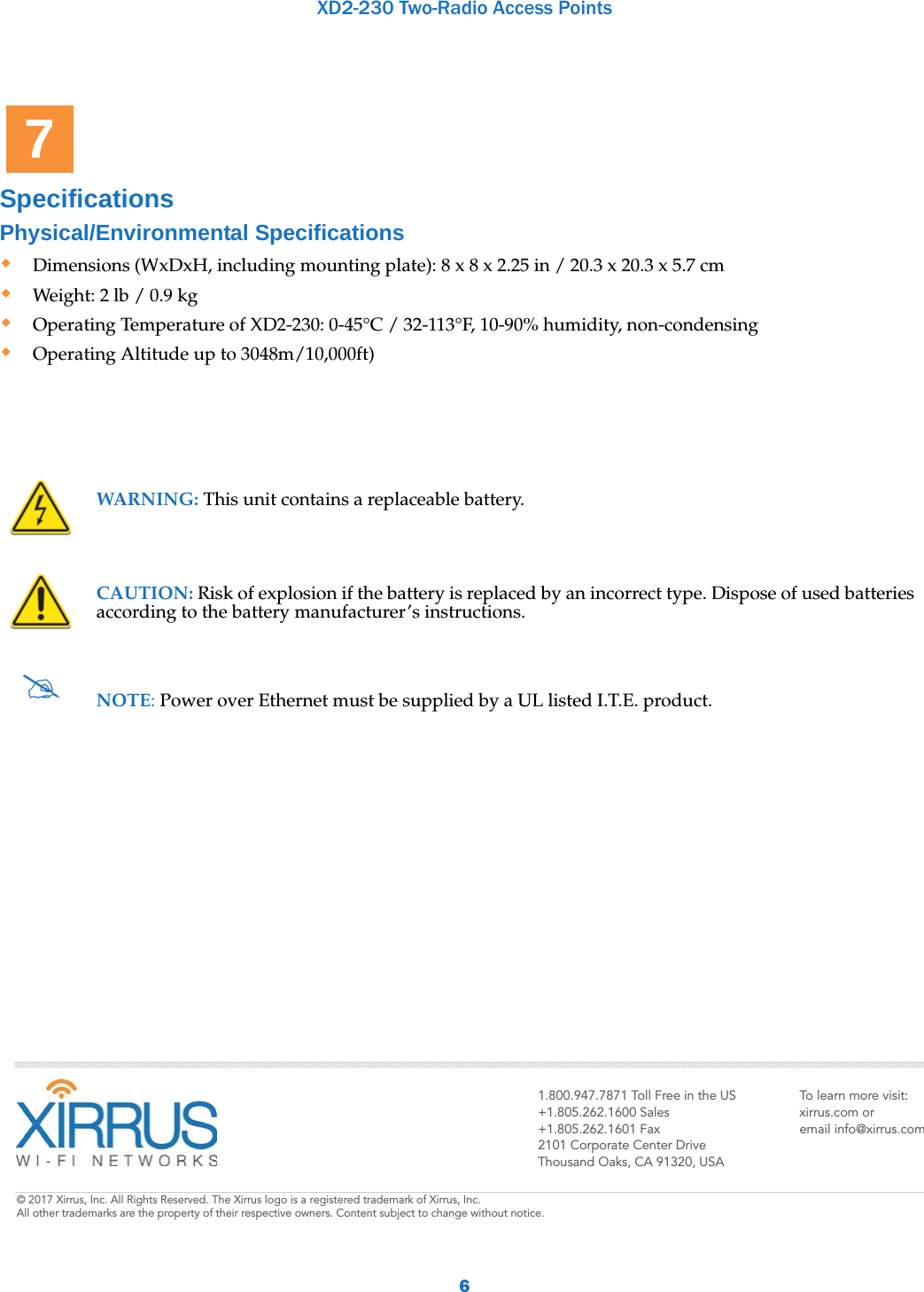
Users Manual_revised0815

XD2-230 Two-Radio Access Points1Quick Installation Guide  For the XD2-230 APThe XD2-230 Access Point (AP) is part of the Xirrus wireless portfolio. With two omnidirectional 802.11ac radios, an integrated controller, and cloud management, this AP delivers robust wireless connectivity. The XD2-230 (Model XD2230) AP’s radio1 is a dual-band (2.4GHz/5GHz) 3x3 802.11ac Wave 1 radio, set to 2.4GHz by default. Radio2 is a 5GHz-only Wave 2 radio.This Guide covers the steps required to install and start these APs. You Need the Following ItemsPower and Ethernet connection(s) to your wired network using Cat 5e or Cat 6 cables:GIG1/POE—This Gigabit port powers the AP via Power over Ethernet (PoE) using a Cat 5e or Cat 6 cable that also carries data traffic. See below for Power details.GIG2—This second, data-only Gigabit port is only available on the XD2-240, and provides additional bandwidth. Its use is optional. Connect with Cat 5E or Cat 6 cable.AP must be connected to PoE networks without routing cabling to the outside plant. This ensures that cabling is not exposed to lightning strikes or possible crossover from high voltage lines. AP, PoE injectors, and switches must be installed and used indoors. The total Cat 5e or Cat 6 cable length from the switch to the AP must be no more than 100 m, including all cable segments. Power—See the matrix below to select a compatible PoE switch or Xirrus-supplied injector for your AP. XD2 models require 802.3at. If using an injector, you must provide a data connection from the switch to the injector as well as another cable from the injector's OUT port to the AP’s GIG1/POE port. Apply power to GIG1/POE port only—other AP Gigabit ports will not draw power if connected to a powered switch port, and AP LEDs will not light.If you are using a POE switch, it is imperative that you know that the switch has sufficient power budget to power all connected devices. Xirrus XD2 APs are Type 2, Class 4 POE-802.3at devices. If your switch vendor provides a setting for the type of powered-device detection with options such as Legacy, 4-Point, or BOTH, set the port to BOTH or 4-Point. Do not use settings intended for legacy devices. AP TypeGeneric PoE+Injector or Switch(802.3at)Xirrus PoE+ Switch(802.3at)XP1-MSI-30XP1-MSI-75MXP1-MSI-75(POE-75U-1UP-X)XP8-MSI-70MXP2-MSI-95MXD2-230     1
XD2-230 Two-Radio Access Points2Access to a Web browser to configure the AP via the Xirrus Management System or directly via the AP’s Windows Management Interface (WMI). For a suspended ceiling mount, you need a 7/16” nut driver to attach the mounting plate to the T-Bar clips. (See “Install Mounting Hardware” on page 3.) Do not use old T-Bar clips or studs from XN or XS APs with the X2 and XD2 Series—they will damage the AP case.NOTE: Leave protective plastic film on the AP until installation is complete to avoid leaving marks on the AP.Mounting Options Direct Ceiling Mount—for a more secure mount, use the furnished mounting plate with at least two user-supplied screws. Or you may mount directly to the ceiling with two user-supplied screws (we recommend max screw size #8, Pan Head type). In either case, you must use screws that are appropriate for the ceiling construction material. Suspended Ceiling Grid Mount—See photos at right and on Page 3. Use the mounting plate with the two supplied T-Bar clips (for 15/16” ceiling grid). For a slotted ceiling grid, T-slot bolts are available for attaching the mounting plate to slots in the grid. Wall Mount—use a Wall Mount Accessory Kit (XE-500-WALL), which contains a mounting plate, wall mount bracket, and three screws (1/4” Plastite).Choose a Suitable LocationChoose an indoor location that is central to your users, that is away from heat sources. To ensure good air flow, it is essential that the AP’s vents are not blocked.The AP should be installed parallel to the ground (i.e., in a horizontal position, not tilted on its side). The AP should not be more than 30 feet (9m) above the ground (or the level at which receiving devices will be used). For atypical installations, please verify the resulting signal coverage. The location must be capable of supporting the weight of the AP and the mounting bracket (about 2 lb total). For optimal placement, we recommend that a predictive survey be performed by a qualified Xirrus partner. Maintain a distance of at least 50 feet (15m) between additional APs. Keep the unit away from electrical devices or appliances that generate RF noise—at least 3 to 6 ft (1m - 2m).AP Mounting Plate (front)This side faces the AP2
XD2-230 Two-Radio Access Points3Install Mounting Hardware 3A—Ceiling Mount We recommend use of the supplied AP mounting plate, which offers a more secure mount and ease of dismount. 1. Remove the mounting plate from the back of the AP (push it against the AP and twist it to the left). Use the holes on the mounting plate to mark the placement of at least two user-supplied screws to install in the ceiling. If not using the mounting plate, mark the locations for the two mounting screws on the ceiling—the centers are 3.5” (8.9 cm) apart. 2. Drill and prepare holes for the screws as appropriate. 3. Cut an access hole for the cable(s) in the ceiling and draw enough cable through to attach to the AP after it is installed.4. If using the mounting plate, align it over the prepared holes. Secure the plate with the screws. Do not over-tighten.If not using the mounting plate, install two screws at the marked locations so that they protrude 1/8” (.3 cm) between the mounting surface and the head of the screw.5. Proceed to “Connect Cables and Install AP” on page 4.NOTE: The AP must not be disassembled! If not using the mounting plate, do not remove the back of the AP to tighten the screws after mounting to ceiling.3B—Ceiling Grid Mount with Mounting Plate1. Remove the mounting plate from the back of the AP (push it against the AP and twist it to the left). For T-Bar clips, use two of the four holes on the AP mounting plate to mark the placement of two T-Bar clips on the metal ceiling support grid. Twist the two supplied T-Bar clips onto the metal ceiling grid at the marked locations and tighten the screw posts to 10-12 lbf.ft (1.38-1.66 kgf.m). Do not over- tighten the screw posts. 2. Cut an access hole in the ceiling tile and draw the cable(s) through. 3. Align the AP mounting plate over the screw posts of the T-Bar  clips and secure it to the two posts using the nuts provided. Tighten the nuts to 10-12 lbf.ft (1.38-1.66 kgf.m), but do not over tighten. 4. Proceed to “Connect Cables and Install AP” on page 4.3A—Ceiling Mount3B—Ceiling Grid Mount with Mounting Plate3C—Wall Mount with Bracket3
XD2-230 Two-Radio Access Points43C—Wall Mount with Bracket NOTE: The mounting location must be able to support the weight of the AP and the mounting bracket (about 2 lb. total). Connect Cables and Install APNOTE: Once you connect the AP's GIG1/POE port, an automatic upgrade typically starts soon after the AP has Internet connectivity. Do not unplug this port while booting or during the upgrade process or the AP may become inoperable. The upgrade should take 10 minutes or less depending on bandwidth.1. Remove the mounting plate from the back of the AP (push it against the AP and twist it to the left). Align the three holes in the wall bracket (ordered separately, see Page 2) over the corresponding mounting plate holes, indicated in the photo. The wall bracket’s small locking tab should point down toward the mounting plate.NOTE: Use only the screws provided in the accessory kit. Other screws that seem equivalent in size may damage the mounting plate. 2. Use the three screws provided in the accessory kit to attach the wall mount bracket to the AP mounting plate. 3. Use the Wall Mounting Bracket as a template and mark the locations on the wall for the mounting holes. The bracket must be secured to the wall in 3 places. When marking the holes, make sure the mounting plate is level.4. Attach the mounting plate to the wall with three user-supplied screws appropriate to the wall construction type.5. Cut an access hole for the cable(s) in the wall and draw enough cable through to attach to the AP after it is installed.6. Proceed to “Connect Cables and Install AP” on page 4.1. Connect the cable that carries power and data to GIGABIT1/POE+ (shown in red). If you use a Xirrus-supplied injector, its CONNECT LED should light (for 70W and higher injectors, it is OK if it blinks). If power is being properly supplied, the AP’s LEDs will light and then commence blinking in their rotating boot pattern. A second data connection may be plugged into GIG2 (optional).  4
XD2-230 Two-Radio Access Points5Zero-Touch Provisioning and Ongoing ManagementMost customers employ the Xirrus Management System (XMS) for the initial setup and continuing management of Xirrus devices. XMS users can readily set up their new devices for provisioning and ongoing maintenance via the following platforms. Set up discovery for the subnetwork of your APs, and create and configure a default profile for newly added APs. When APs are discovered, they are automatically assigned to the XMS default profile and will receive the configuration defined for that profile.XMS-Cloud—performs zero-touch provisioning. Your new APs appear in XMS even before you receive your equipment. When the email arrives with your login information, use XMS-Cloud to specify the initial settings for your APs. A Guided Tour will walk you through the basic steps of creating a profile containing configuration settings, including creating SSIDs and firewall/application control rules. Once the installed AP has Internet connectivity, it will automatically contact Xirrus for cloud-based zero-touch provisioning per your settings, install the latest applicable license, and upgrade the AP to the latest software version as appropriate. XMS-Enterprise—automatically detects and provisions new Xirrus devices deployed in your network via a similar provisioning approach. Set up the SSH Users page in the Discovery section, and create and configure a default profile for newly added APs. After discovery, these new devices automatically receive the configuration defined in your default profile. If you are not using XMS, see the Xirrus Wireless AP User's Guide to configure XD2 APs manually via the Express Setup menu. The User Guide is available from http://support.xirrus.com (login required). Select the Libraries tab and click the AOS - Latest Release link. Using the Reset ButtonThe reset button returns the AP to factory default settings while rebooting. It is located on the bottom of the unit. Use the reset button as follows: Unplug the cable from the GIGABIT1/POE+ port.Press the reset button all the way (there should be a faint click) and hold it.Plug the cable back in and continue to keep the button pressed for 10 seconds. This triggers the factory default reset during the boot process.2. Align the two slots on the back of the AP chassis (circled in red) with the corresponding tabs on the AP mounting plate or with the two screws installed directly in the ceiling. 3. Push the AP chassis up on the mounting plate tabs and rotate the AP to the right until it snaps in place. 4. Remove the protective plastic film from the unit.5. If you need to remove the AP, push it up towards the ceiling and rotate it to the left. 56
XD2-230 Two-Radio Access Points6Specifications Physical/Environmental SpecificationsDimensions (WxDxH, including mounting plate): 8 x 8 x 2.25 in / 20.3 x 20.3 x 5.7 cmWeight: 2 lb / 0.9 kg Operating Temperature of XD2-230: 0-45°C / 32-113°F, 10-90% humidity, non-condensing Operating Altitude up to 3048m/10,000ft)WARNING: This unit contains a replaceable battery.CAUTION: Risk of explosion if the battery is replaced by an incorrect type. Dispose of used batteries according to the battery manufacturer’s instructions.NOTE: Power over Ethernet must be supplied by a UL listed I.T.E. product.71.800.947.7871 Toll Free in the US+1.805.262.1600 Sales+1.805.262.1601 Fax2101 Corporate Center DriveThousand Oaks, CA 91320, USATo learn more visit:xirrus.com oremail info@xirrus.com© 201 Xirrus, Inc. All Rights Reserved. The Xirrus logo is a registered trademark of Xirrus, Inc.  All other trademarks are the property of their respective owners. Content subject to change without notice.
FCC Statement Federal Communication Commission Interference Statement This equipment has been tested and found to comply with the limits for a Class B digital device, pursuant to Part 15 of the FCC Rules.    These limits are designed to provide reasonable protection against harmful interference in a residential installation.  This equipment generates, uses and can radiate radio frequency energy and, if not installed and used in accordance with the instructions, may cause harmful interference to radio communications.    However, there is no guarantee that interference will not occur in a particular installation.    If this equipment does cause harmful interference to radio or television reception, which can be determined by turning the equipment off and on, the user is encouraged to try to correct the interference by one or more of the following measures:  Reorient or relocate the receiving antenna.  Increase the separation between the equipment and receiver.  Connect the equipment into an outlet on a circuit different from that to which the receiver is connected.  Consult the dealer or an experienced radio/TV technician for help.  FCC Caution: Any changes or modifications not expressly approved by the party responsible for compliance could void the user's authority to operate this equipment.  This device and its antenna(s) must not be co-located or operating in conjunction with any other antenna or transmitter.  For product available in the USA/Canada market, only channel 1~11 can be operated. Selection of other channels is not possible.  IMPORTANT NOTE: FCC Radiation Exposure Statement: This equipment complies with FCC radiation exposure limits set forth for an uncontrolled environment. This equipment should be installed and operated with minimum distance 20cm between the radiator & your body.
ISED Statement  This device complies with Industry Canada’s licence-exempt RSSs. Operation is subject to the following two conditions: (1) This device may not cause interference; and   (2) This device must accept any interference, including interference that may cause undesired operation of the device. Le présent appareil est conforme aux CNR d'Industrie Canada applicables aux appareils radio exempts de licence. L'exploitation est autorisée aux deux conditions suivantes : (1) l'appareil ne doit pas produire de brouillage, et (2) l'utilisateur de l'appareil doit accepter tout brouillage radioélectrique subi, même si le brouillage est susceptible d'en compromettre le fonctionnement.  IMPORTANT NOTE: IC Radiation Exposure Statement: This equipment complies with IC RSS-102 radiation exposure limits set forth for an uncontrolled environment. This equipment should be installed and operated with minimum distance 20 cm between the radiator & your body. Cet équipement est conforme aux limites d’exposition aux rayonnements IC établies pour un environnement non contrôlé. Cet équipement doit être installé et utilisé avec un minimum de 20 cm de distance entre la source de rayonnement et votre corps.  The transmitter module may not be co-located with any other transmitter or antenna. Le module émetteur peut ne pas être coïmplanté avec un autre émetteur ou antenne.  CAN ICES-3 (B)/NMB-3(B)    The Country Code Selection feature is disabled for products marketed in the US/Canada

Navigation menu