Cambium Networks XI-AC1300 Wireless Access Point User Manual Xirrus AOS Xirrus
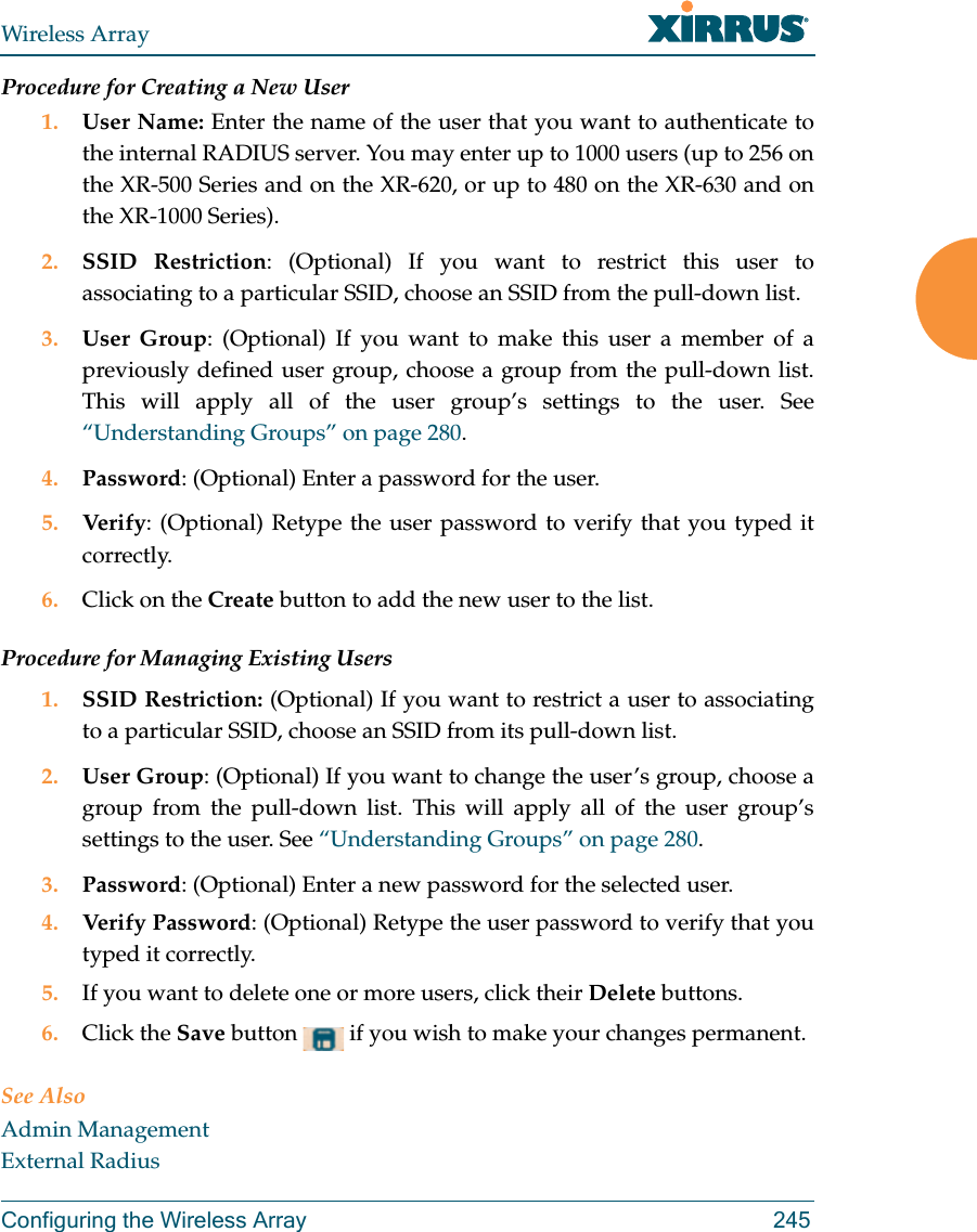
Xirrus, Inc. Wireless Access Point Xirrus AOS Xirrus
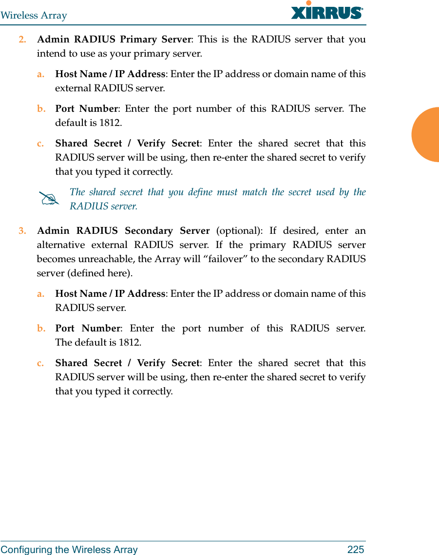
UserManual.wiki
>
Cambium Networks
>
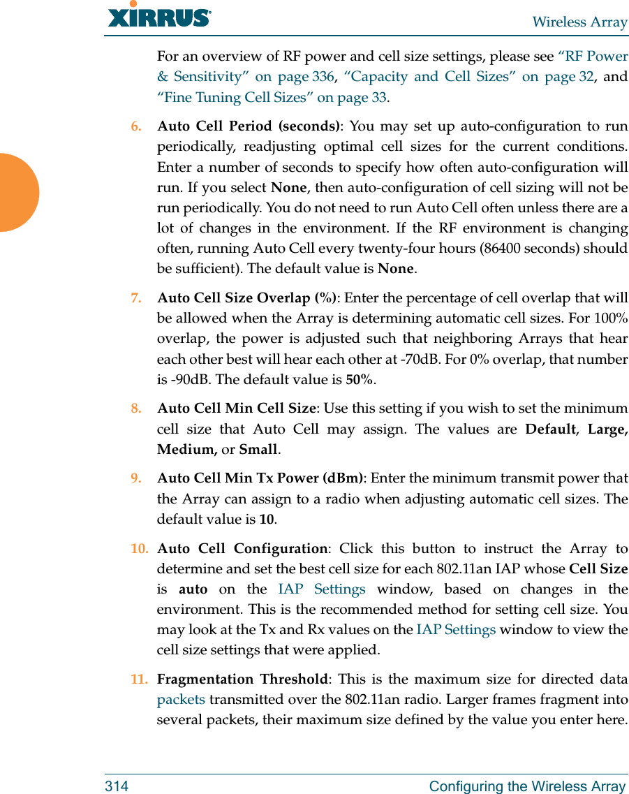
XI-AC1300 User Manual
>
Part 2
Contents
1.
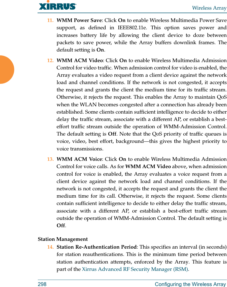
Part 1 DRAFT
2.
Part 2 DRAFT
3.
Part 1
4.
Part 2
Part 2
Navigation menu
Upload a User Manual
Namespaces
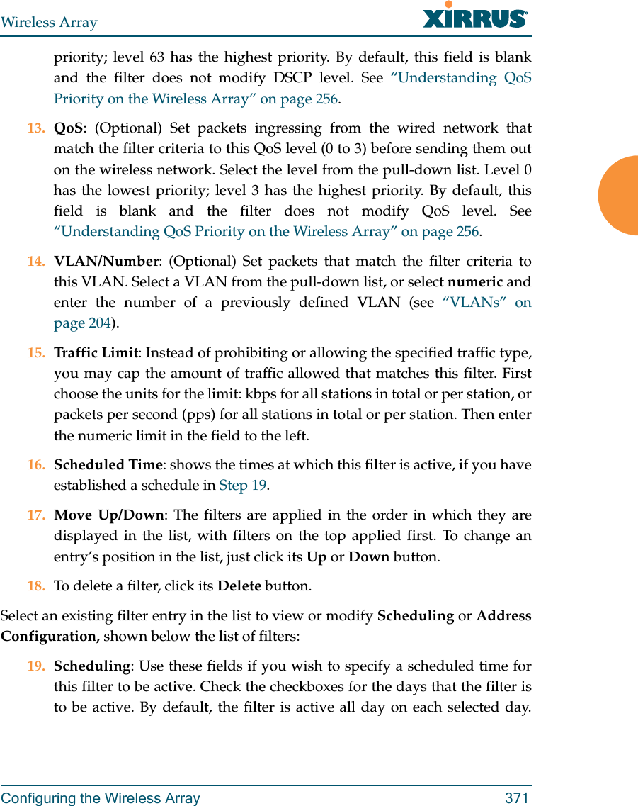
Wiki Guide
HTML
PDF
Info
Views
User Manual
Discussion / Help
Navigation
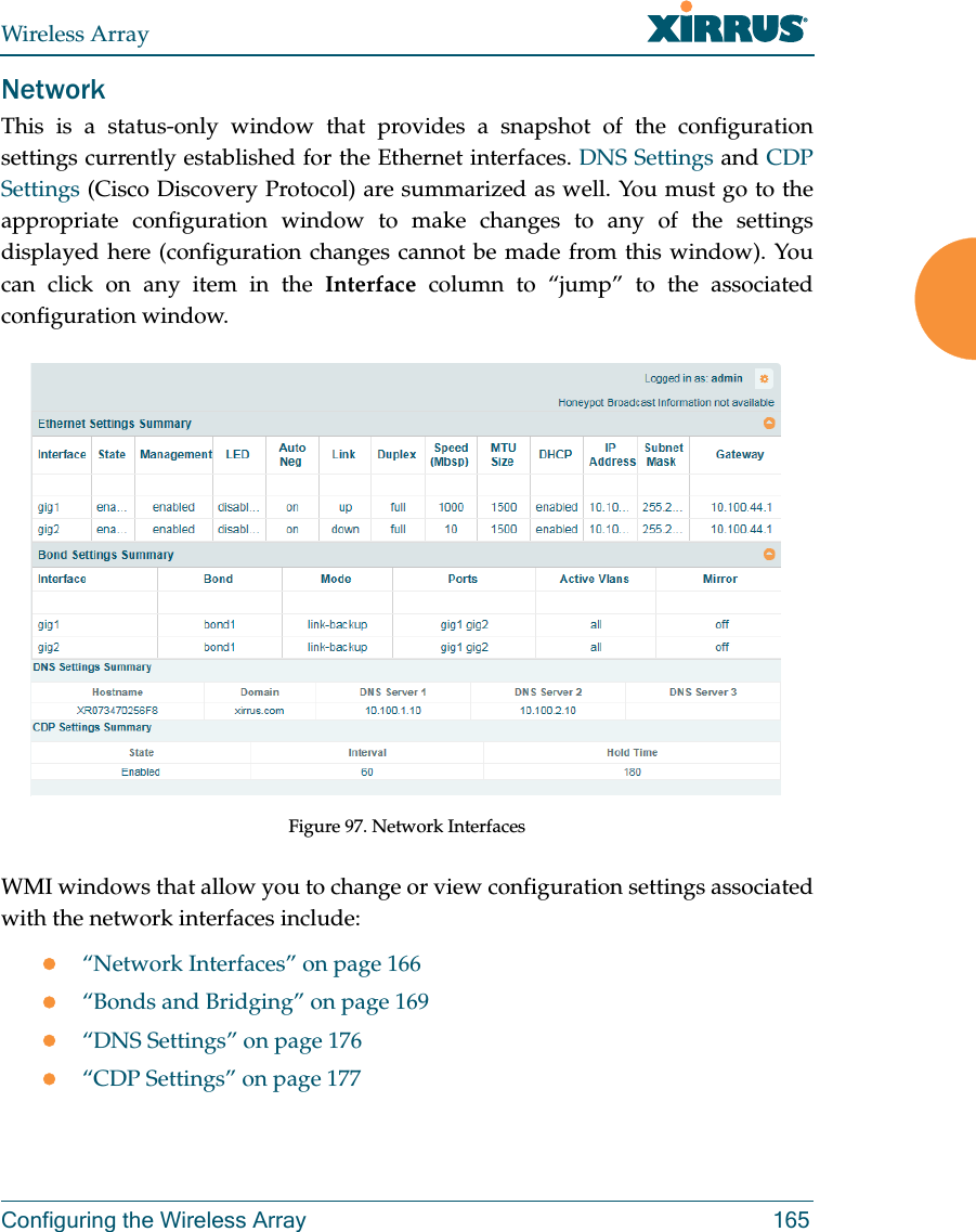
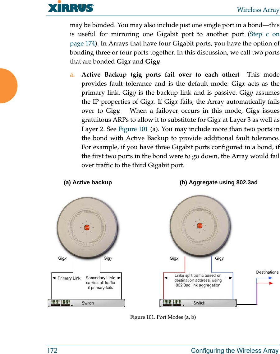
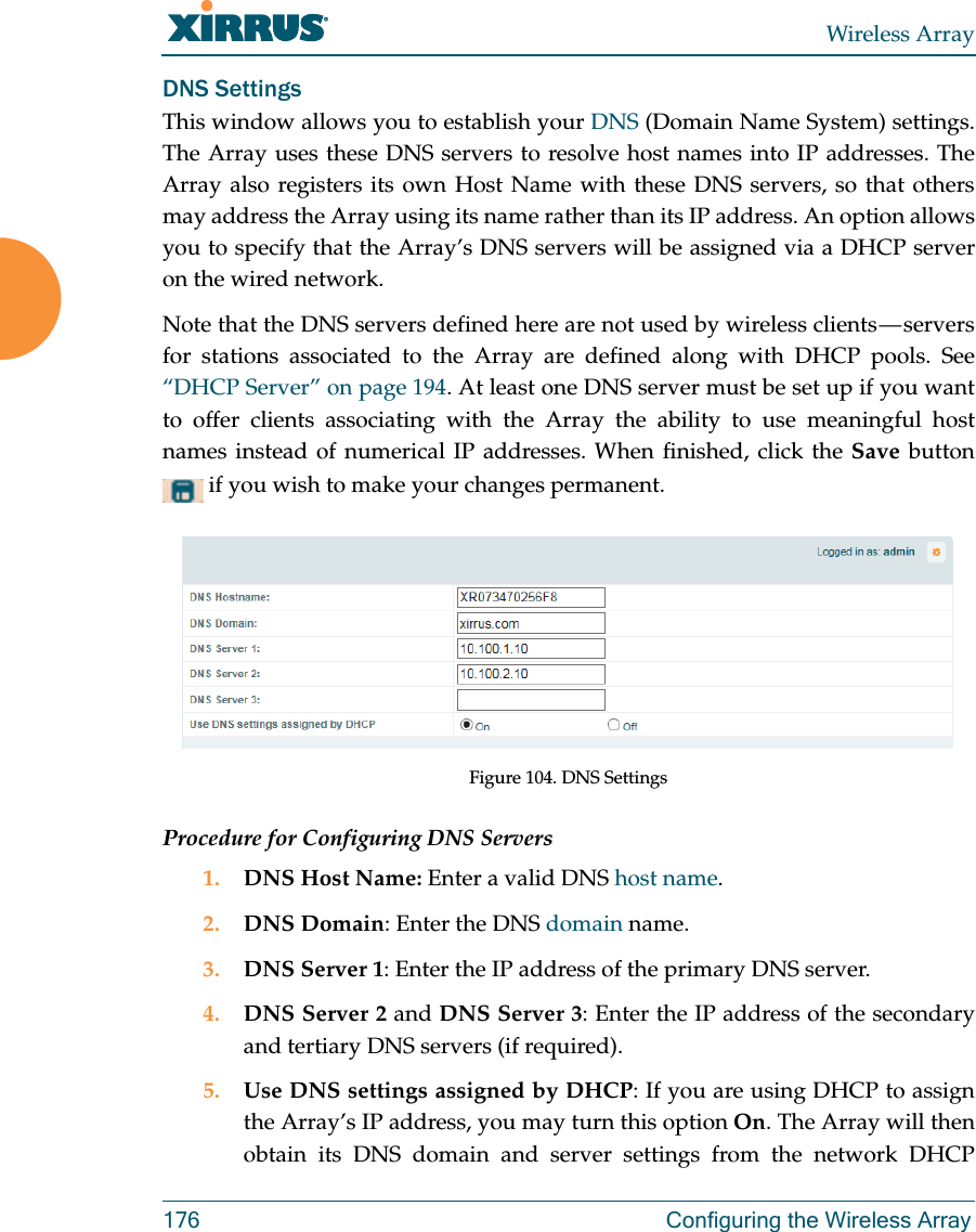

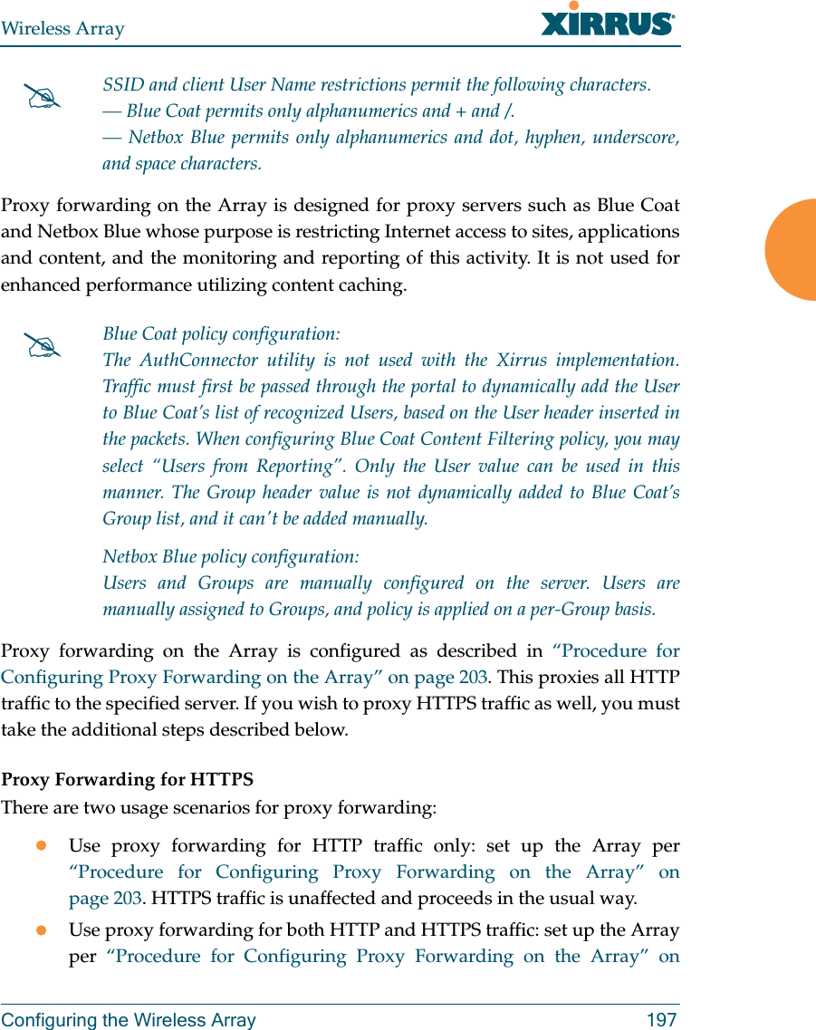
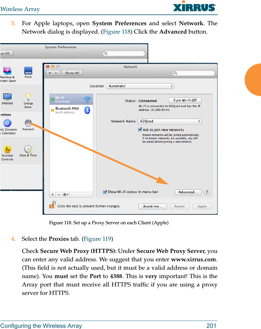
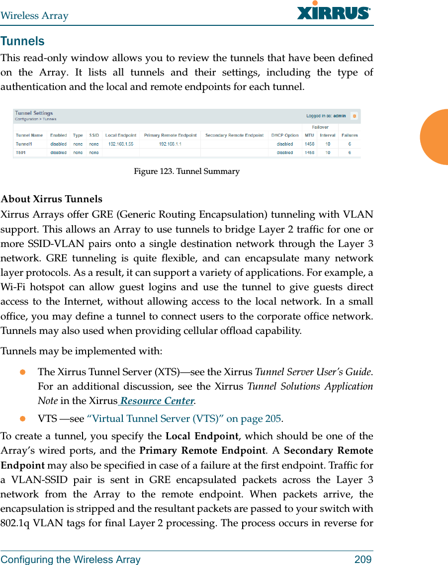
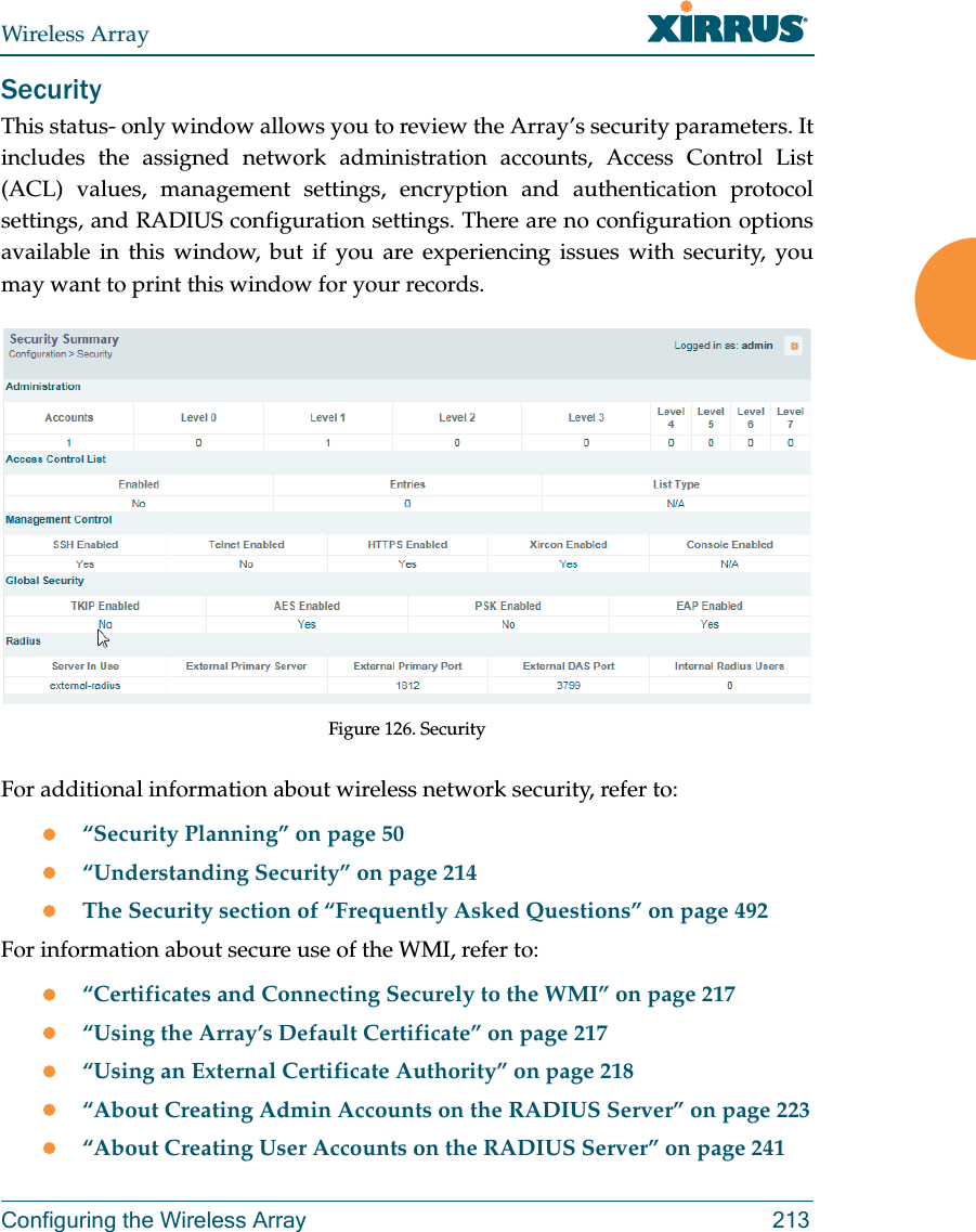
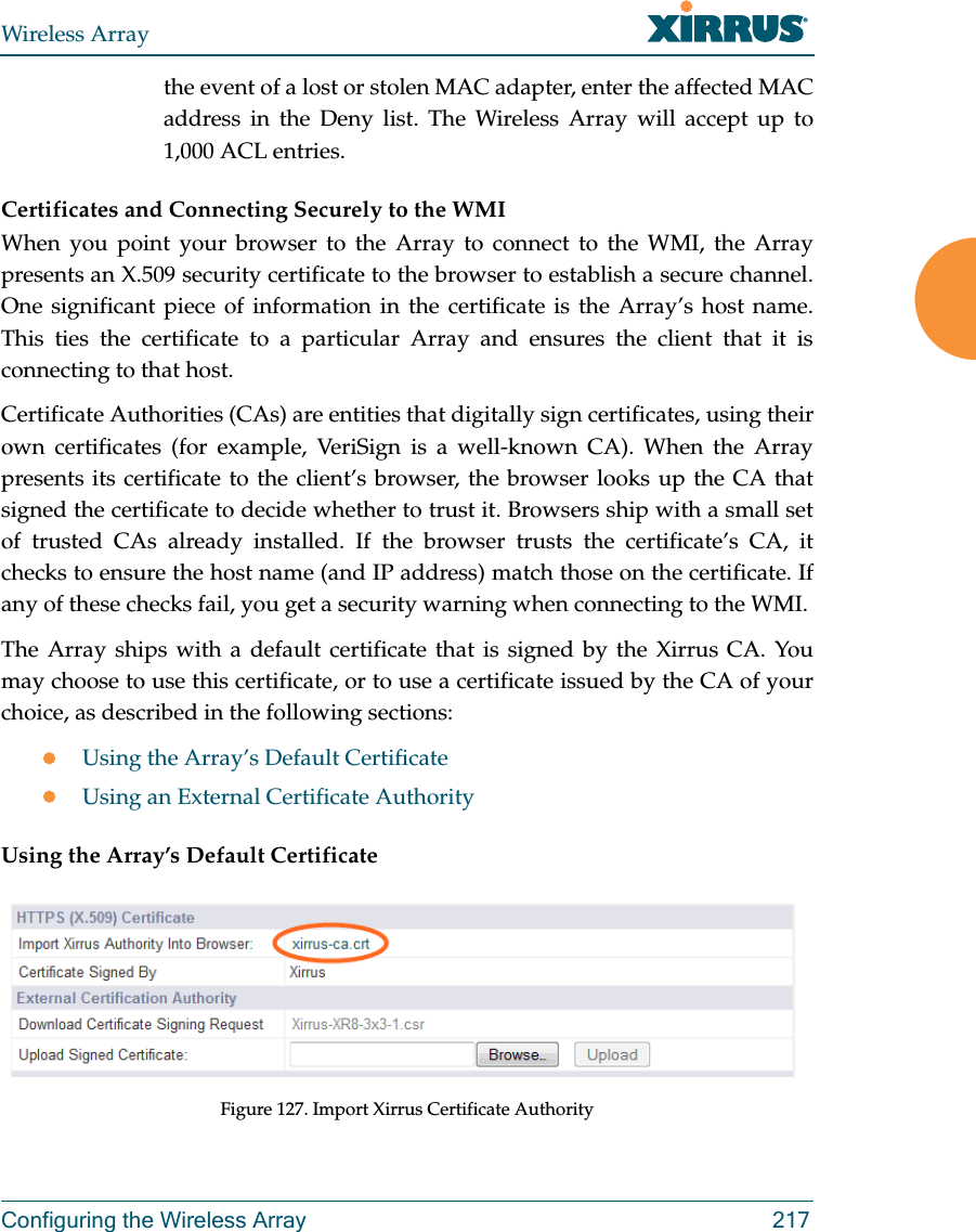
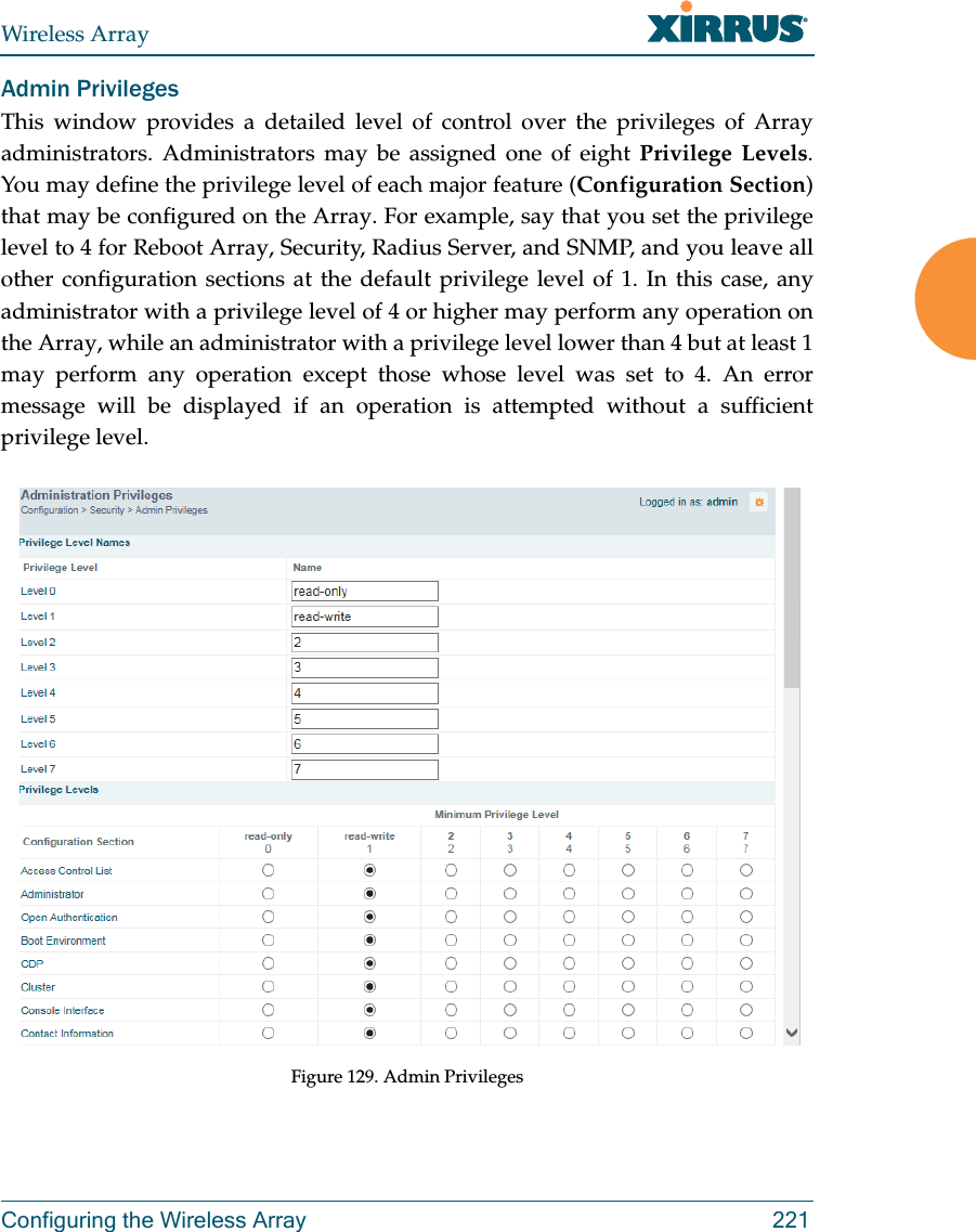
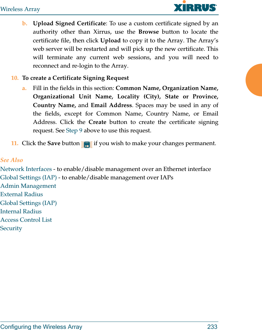
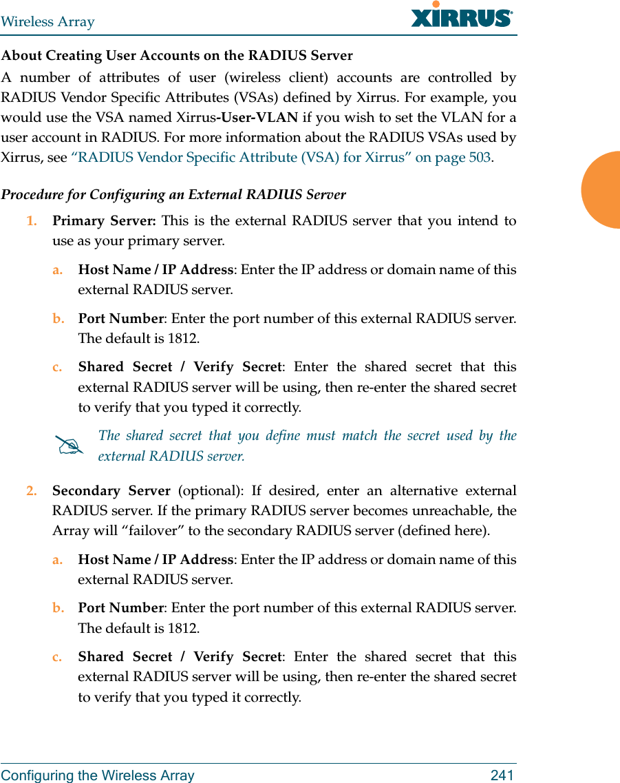
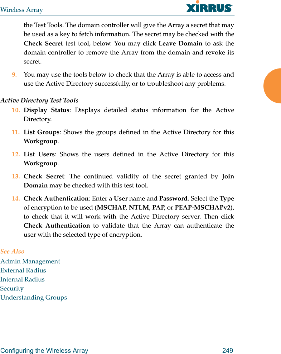
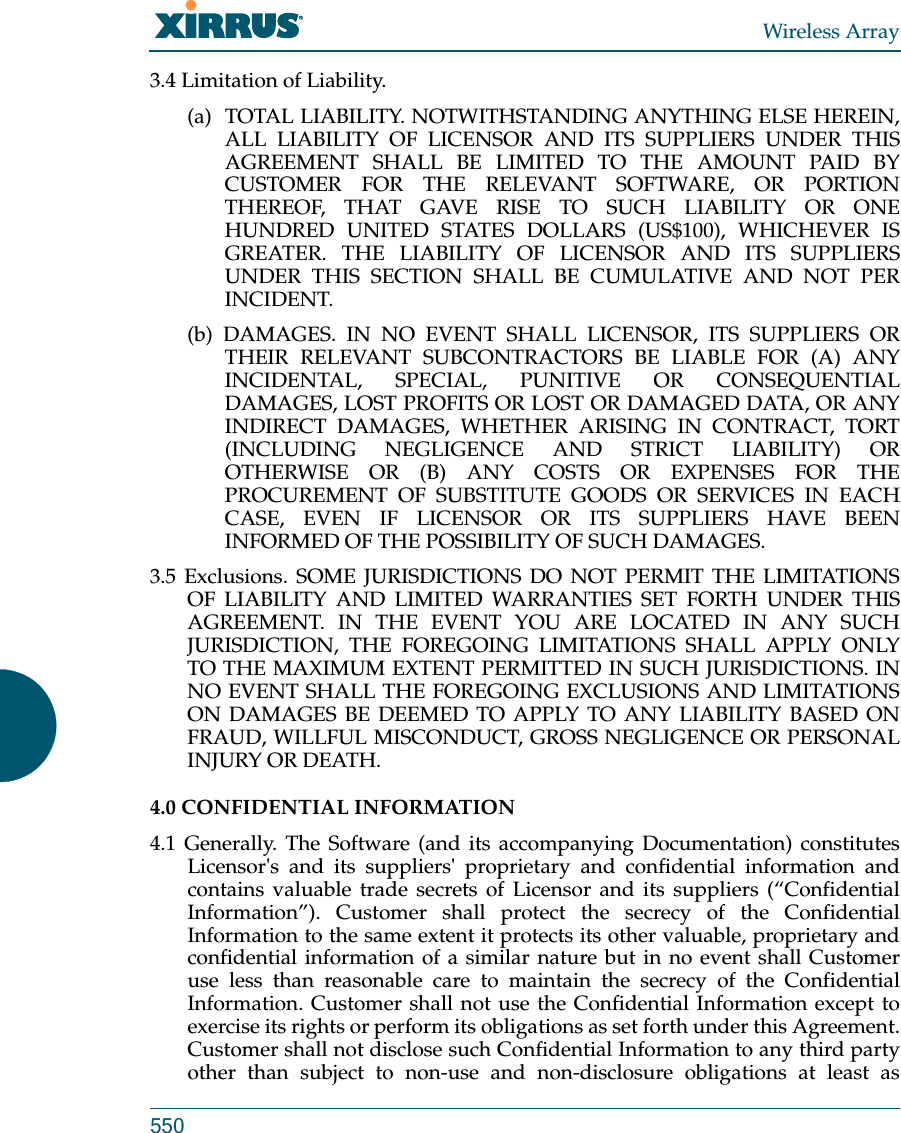
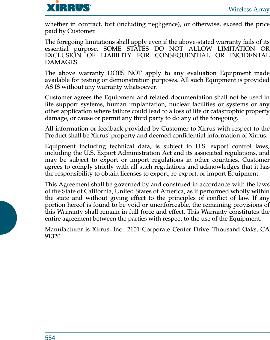
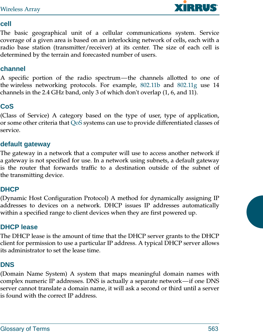
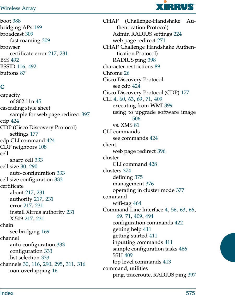
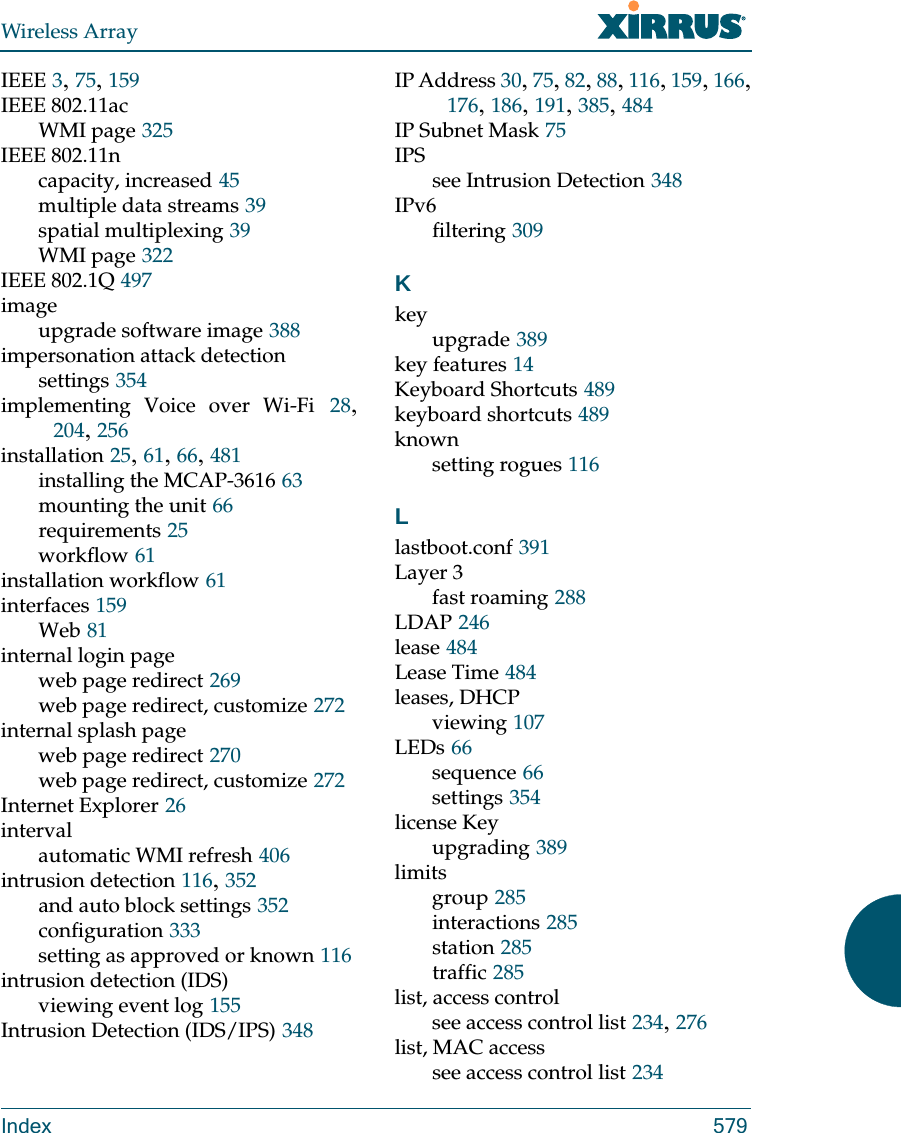
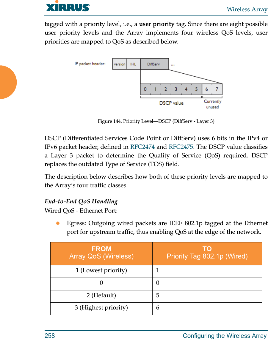
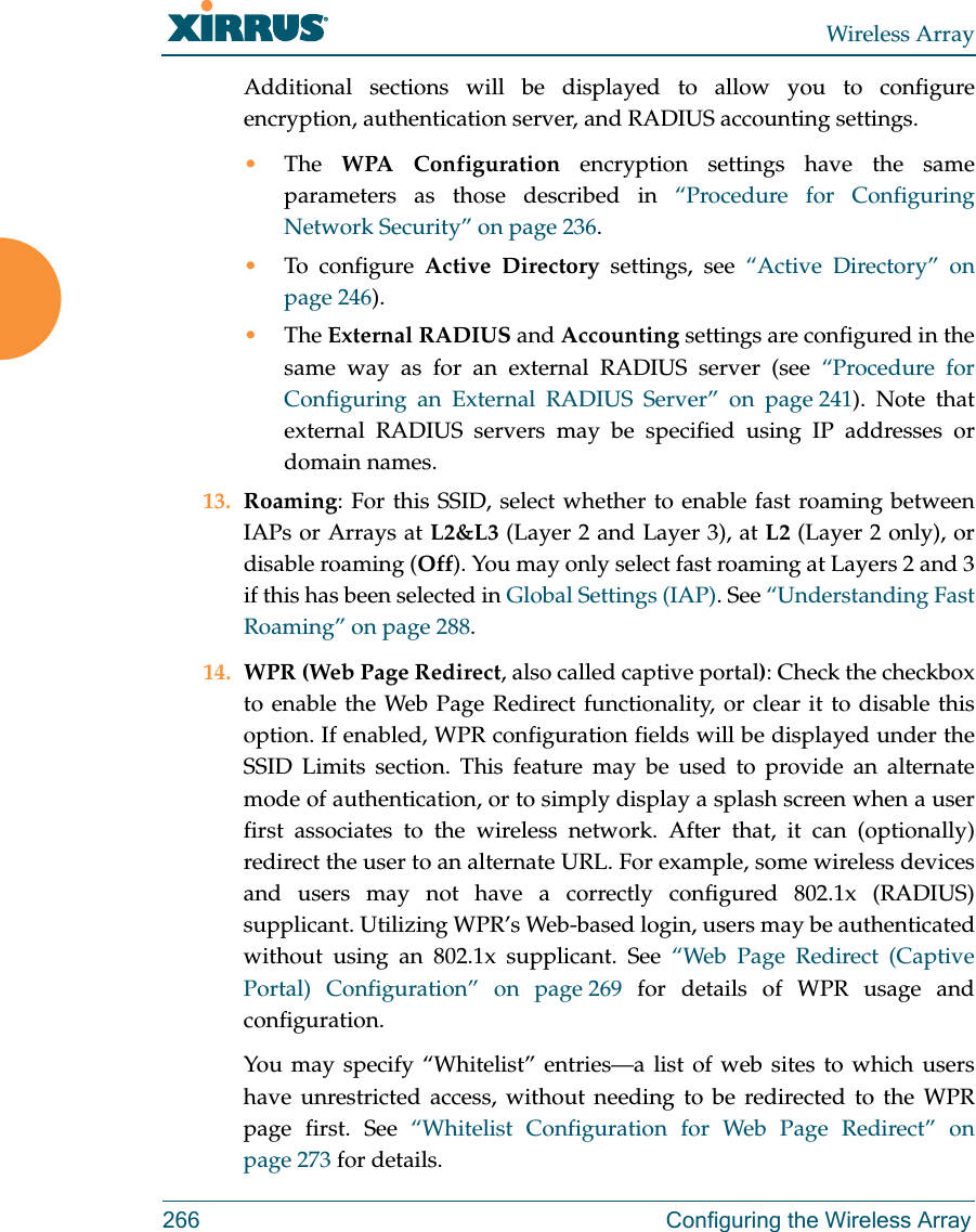
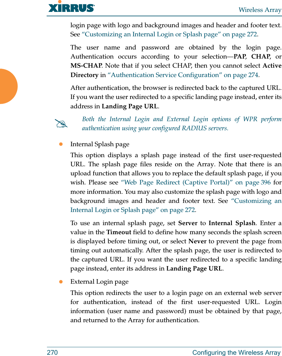
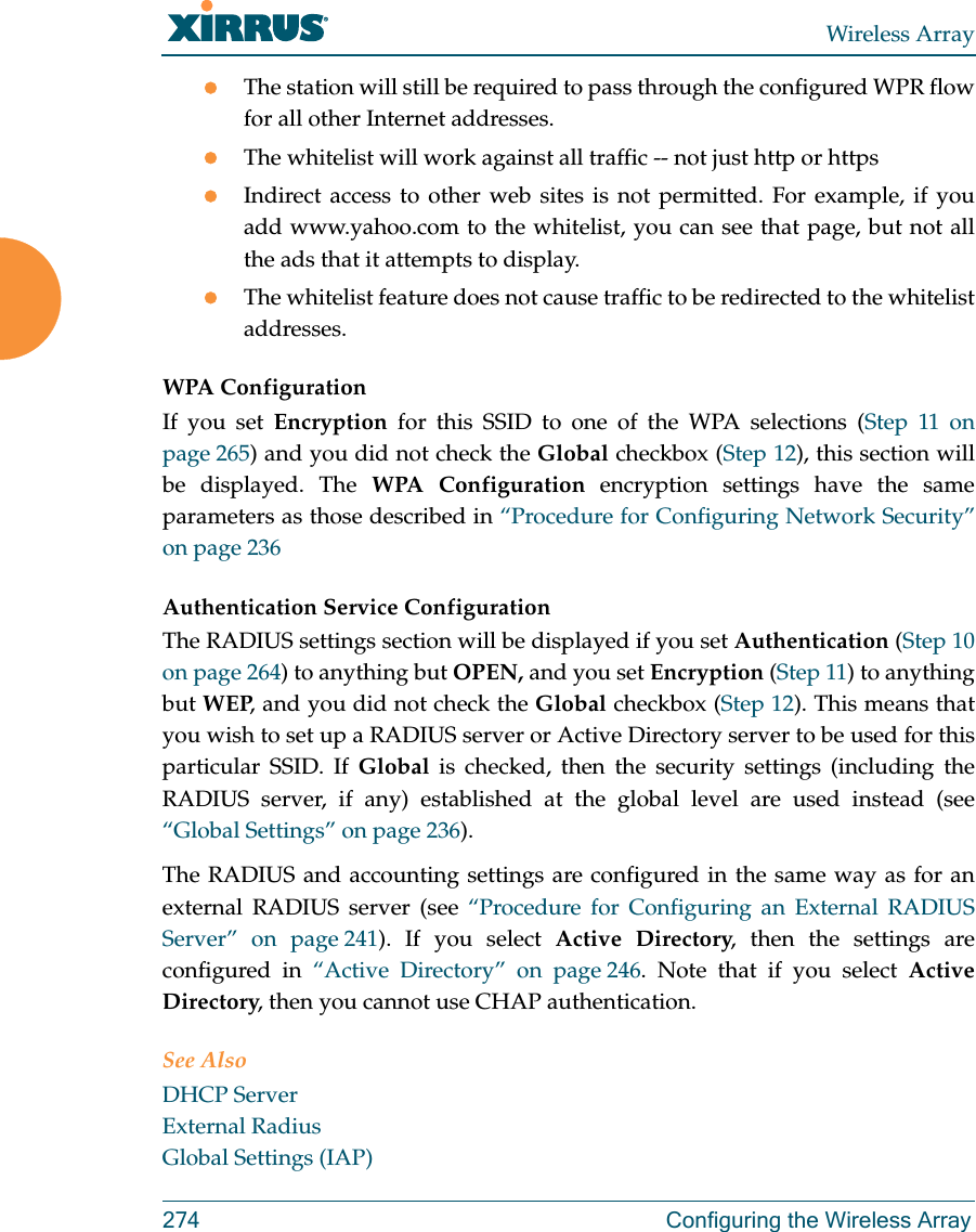
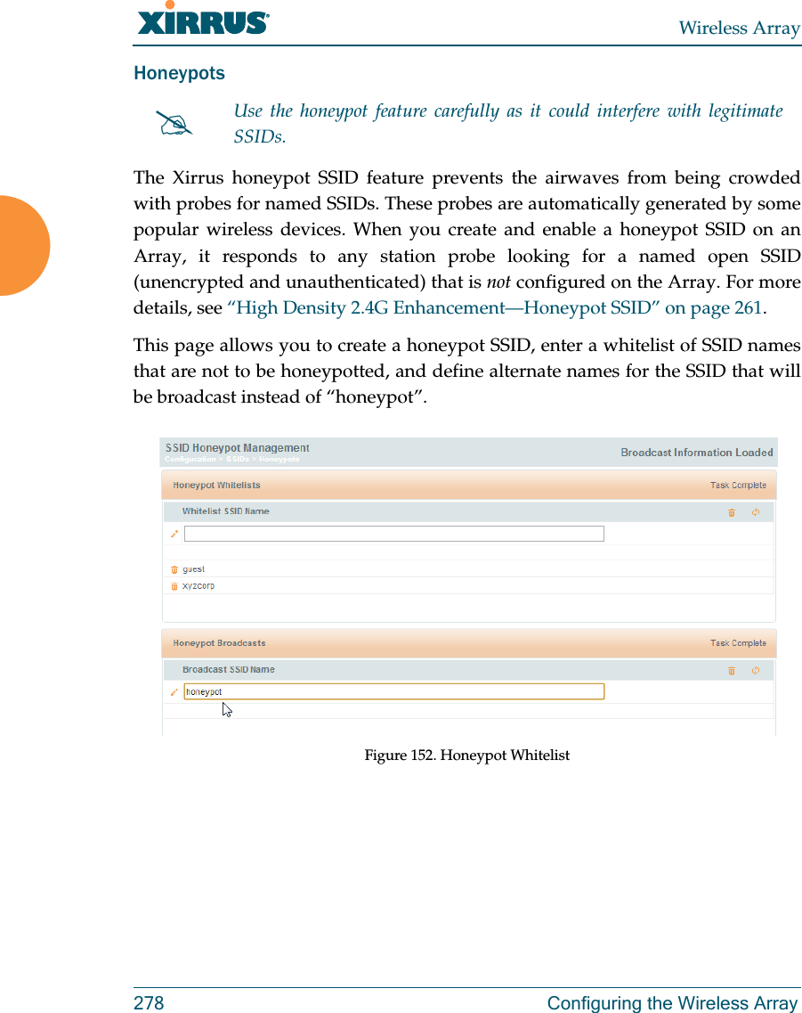
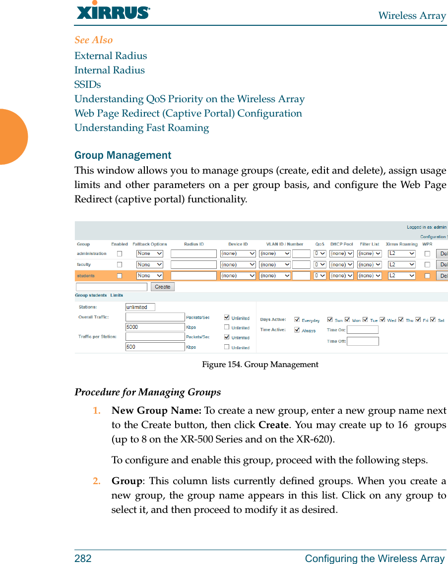
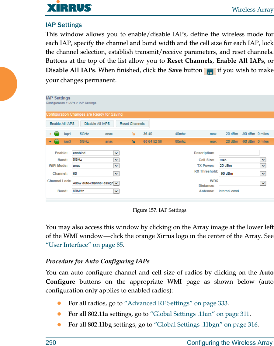
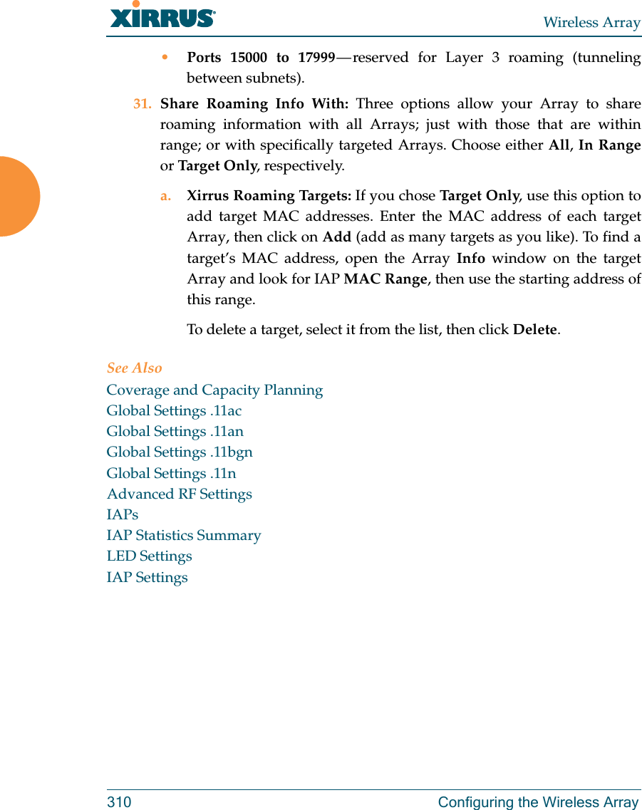
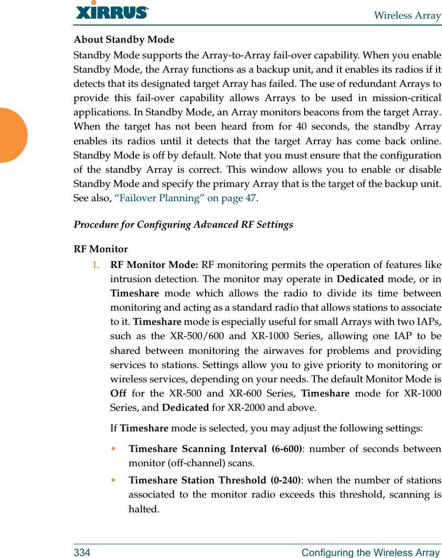
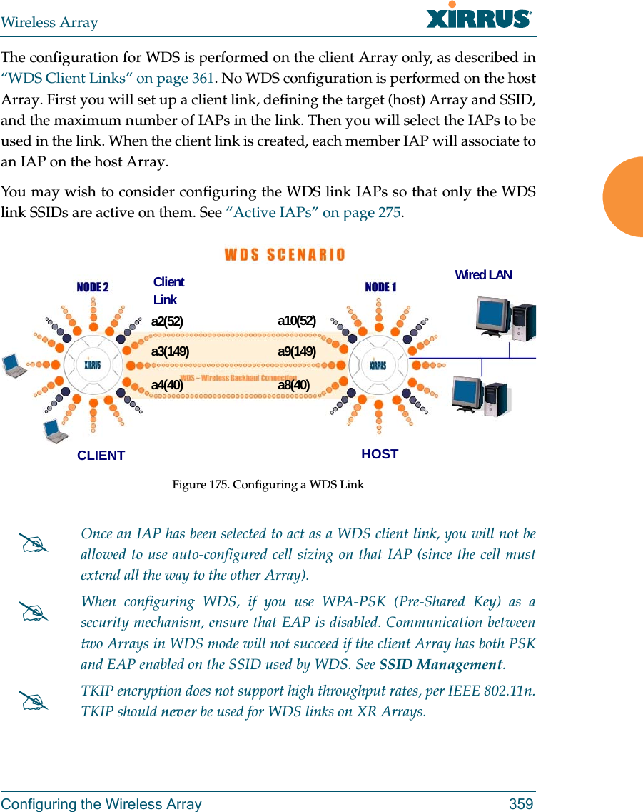
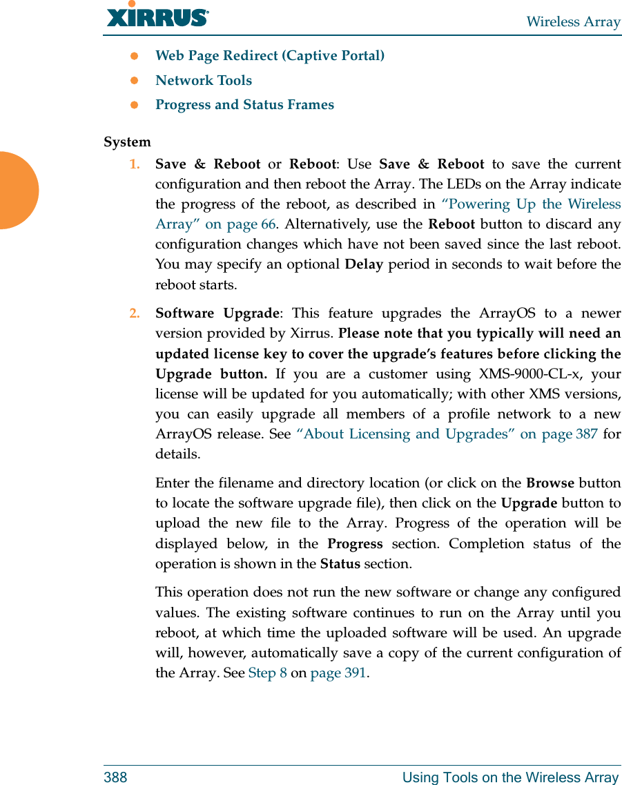
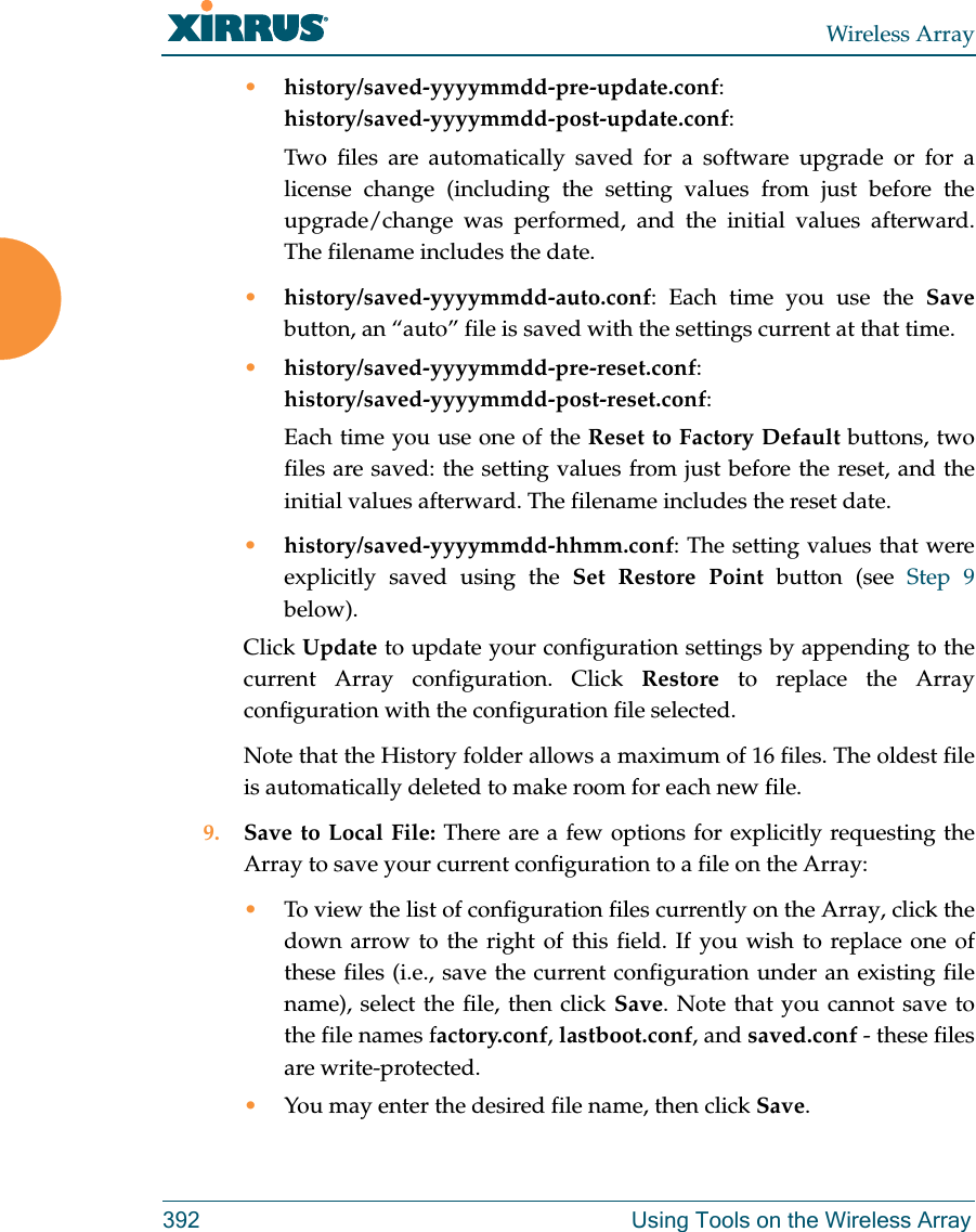
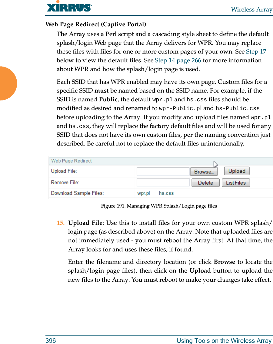
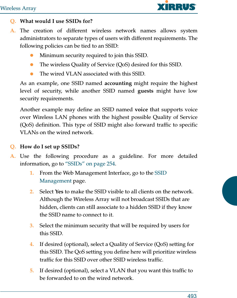
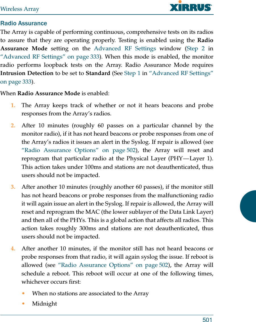
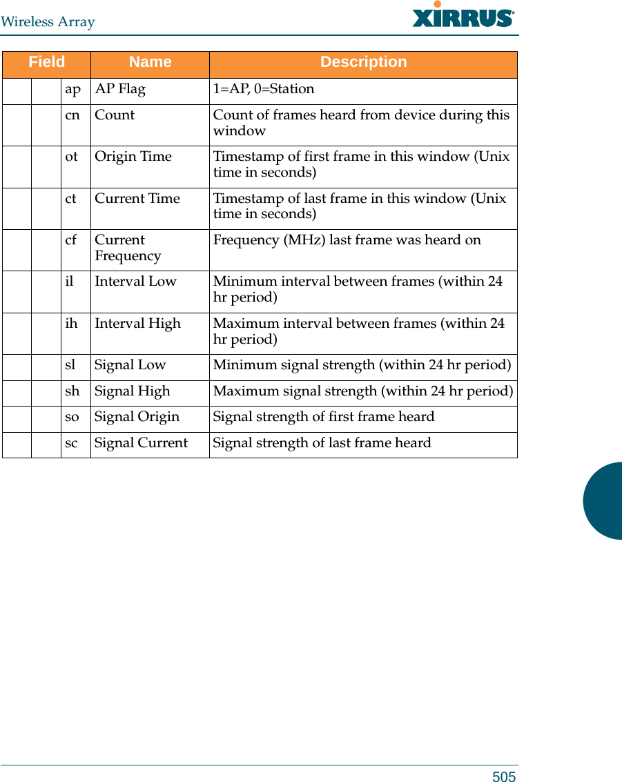
![Wireless Array252 Configuring the Wireless ArrayFigure 140. OAuth 2.0 Management - Token ListProcedure for Obtaining a Token and Accessing RESTful API on the Array1. Present User Credentials for a Permanent TokenA user-developed application must register by presenting the following information to the URL below:https://[Array hostname or IP address]/oauth/authorize •grant_type: password•username: username of an administrator account on the Array.•client_id: username of an administrator account on the Array(username and client_id must match).•password: password for the same administrator account on the ArrayThe OAuth Authorization API provides a permanent token that the application may use to access the RESTful API. This token remains valid until the administrator revokes the token on the OAuth 2.0 Managementpage, unless the token file somehow becomes corrupted or is removed from the Array’s file system. The token will be removed if the original account associated with it is deleted. 2. Access the RESTful APIOnce registration is completed and a permanent token has been provided, your application may access the API using the client_id and the token at the following URL: https://[Array hostname or IP address]/api/v1/[api-name] ](https://usermanual.wiki/Cambium-Networks/XI-AC1300.Part-2/User-Guide-2284763-Page-96.png)
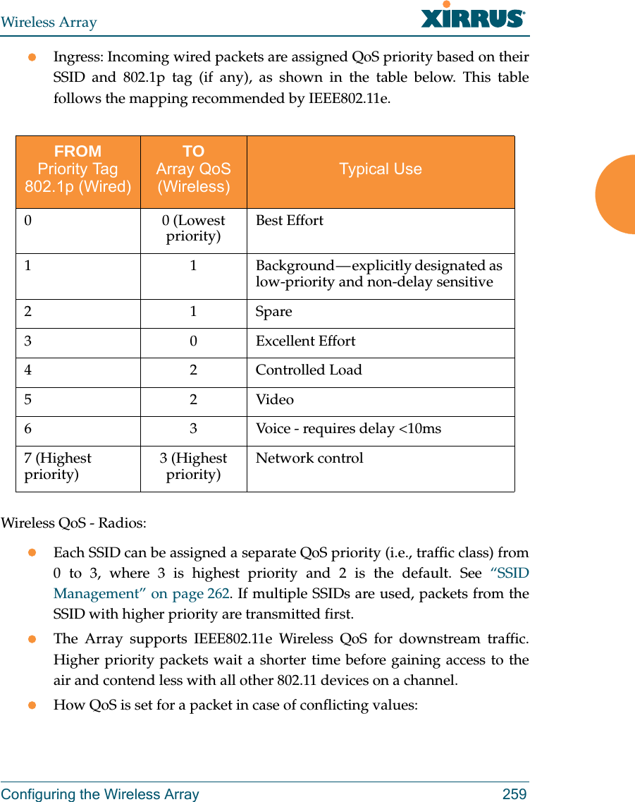
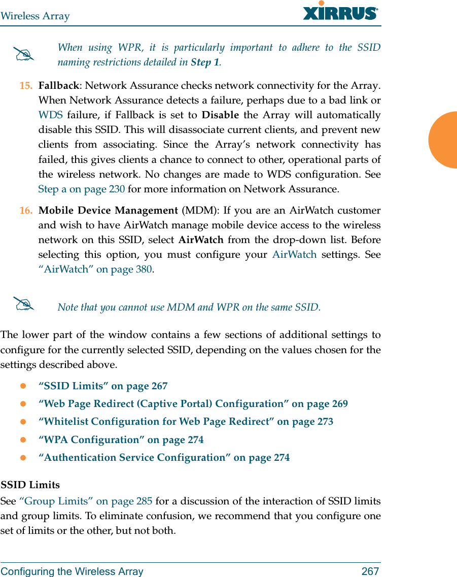
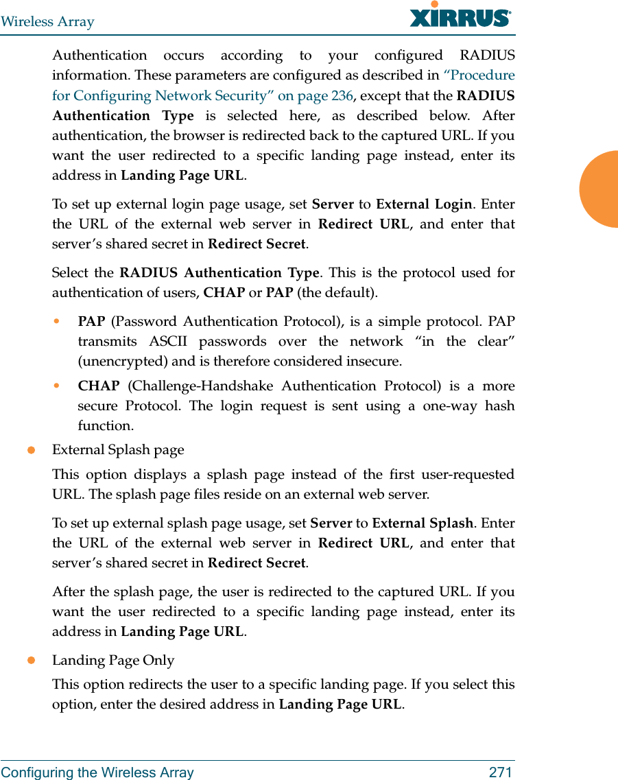
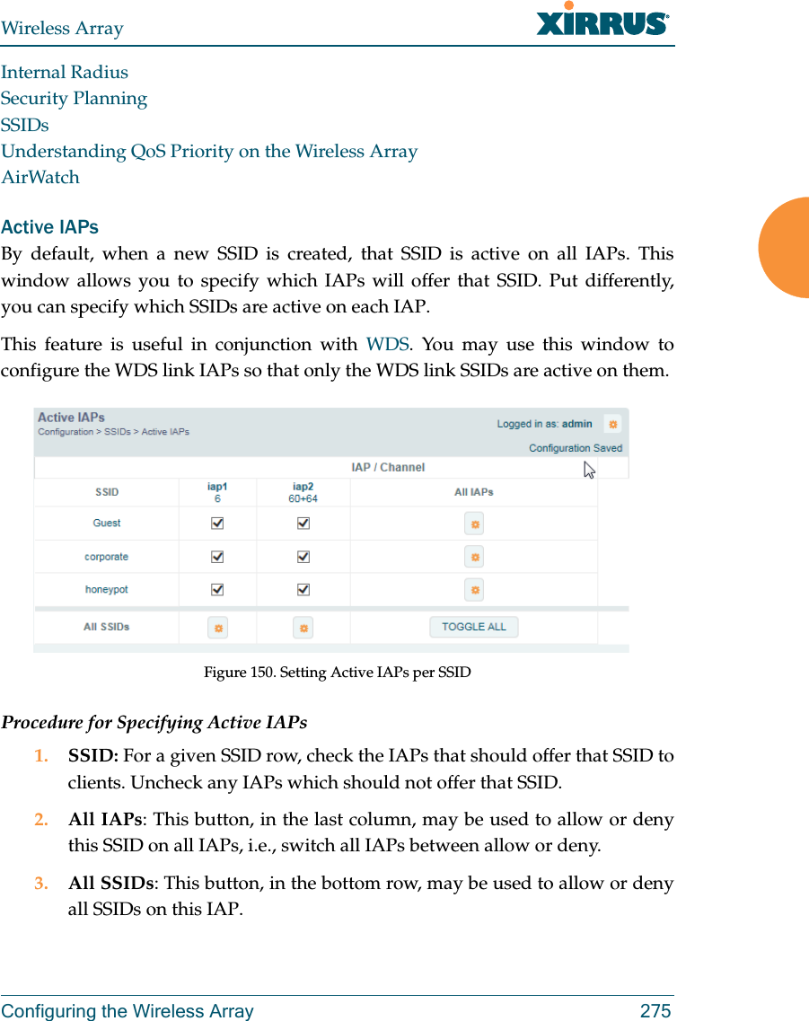
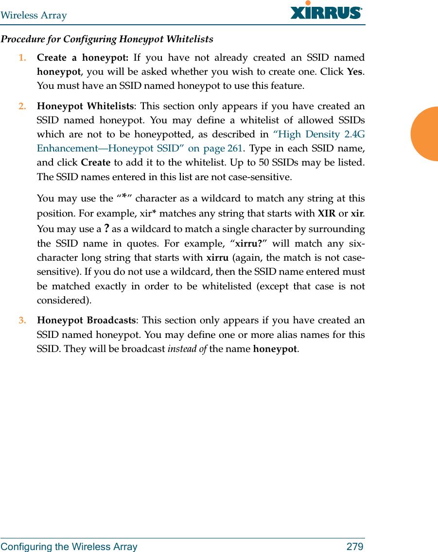
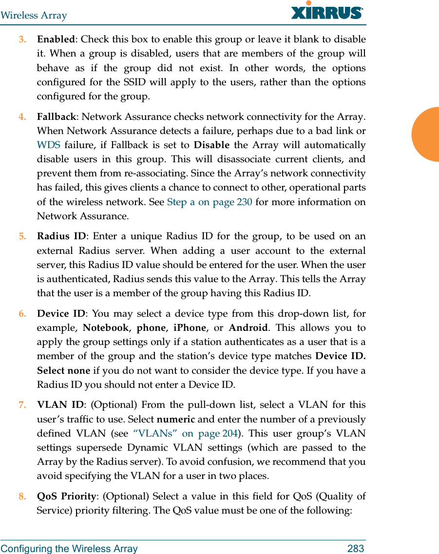
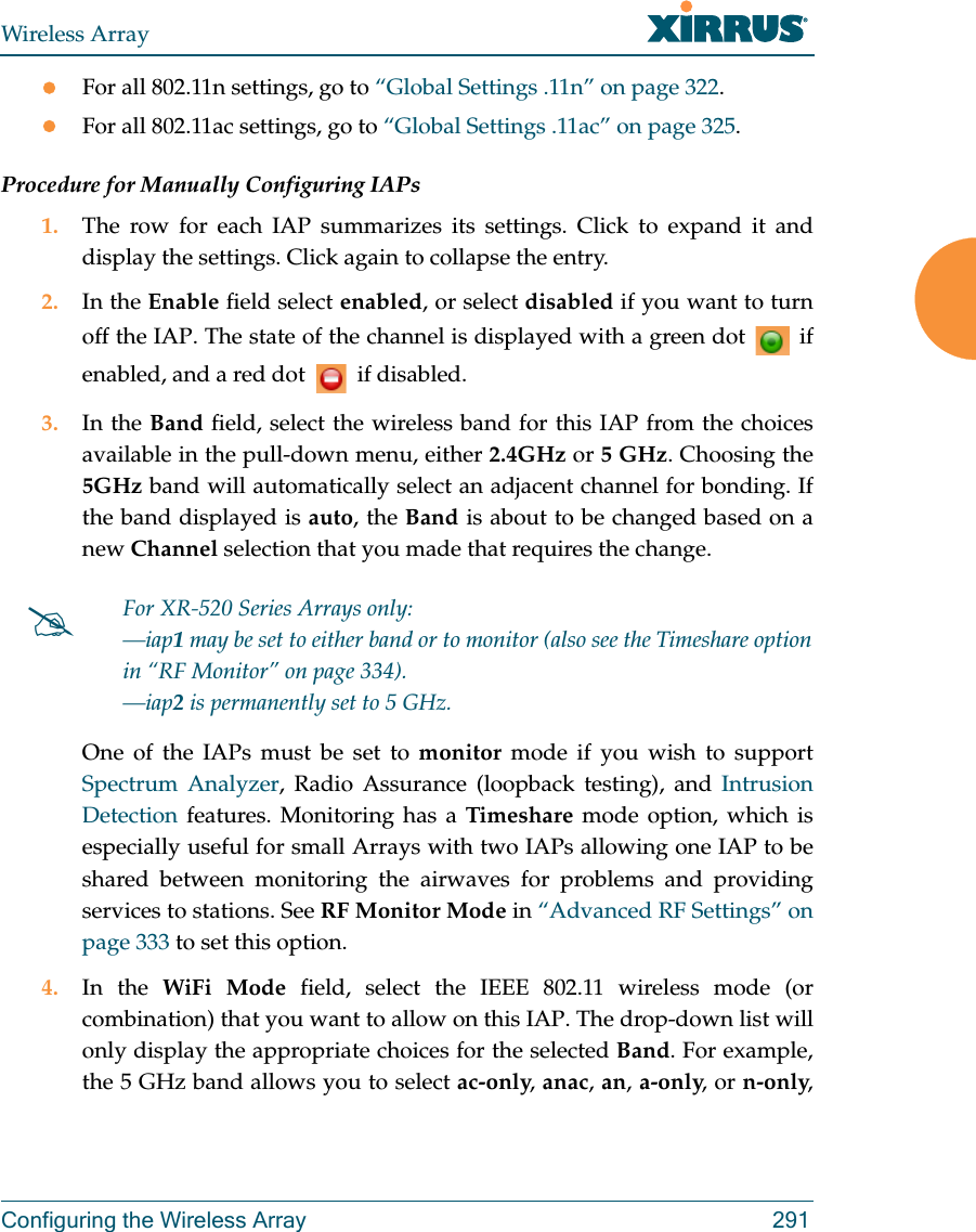
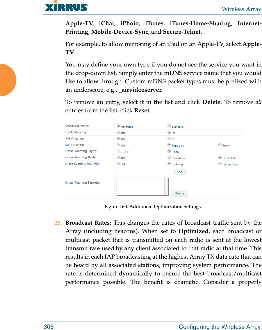
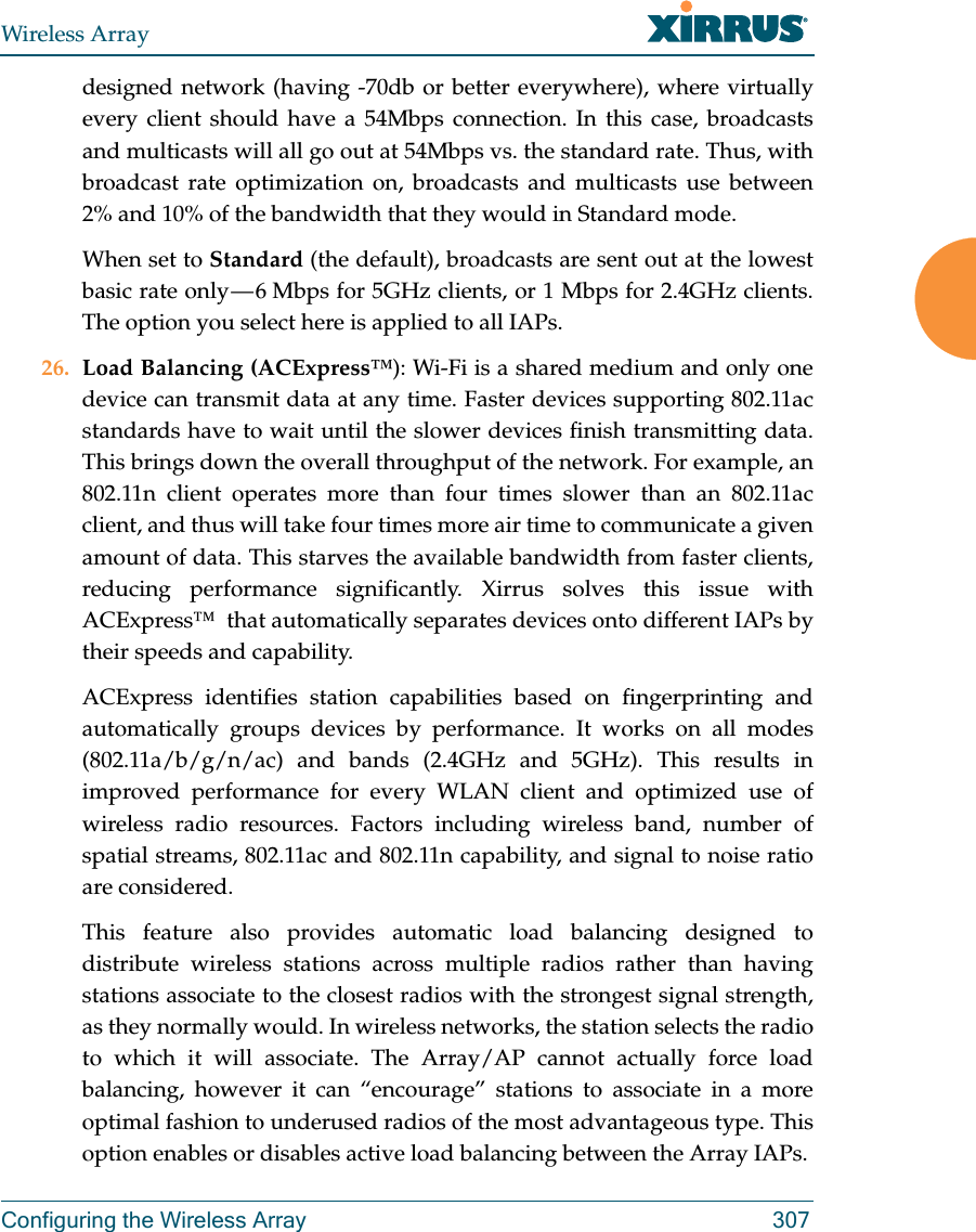
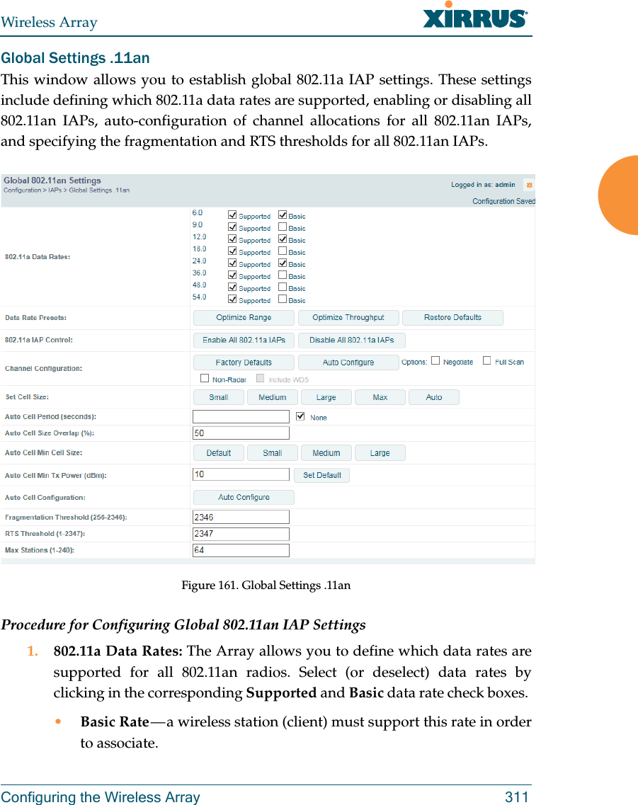
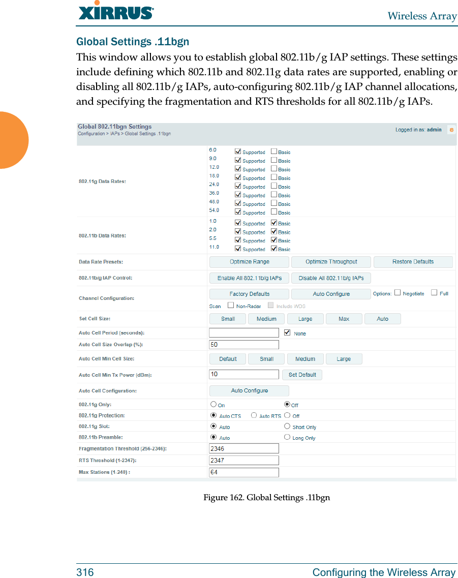
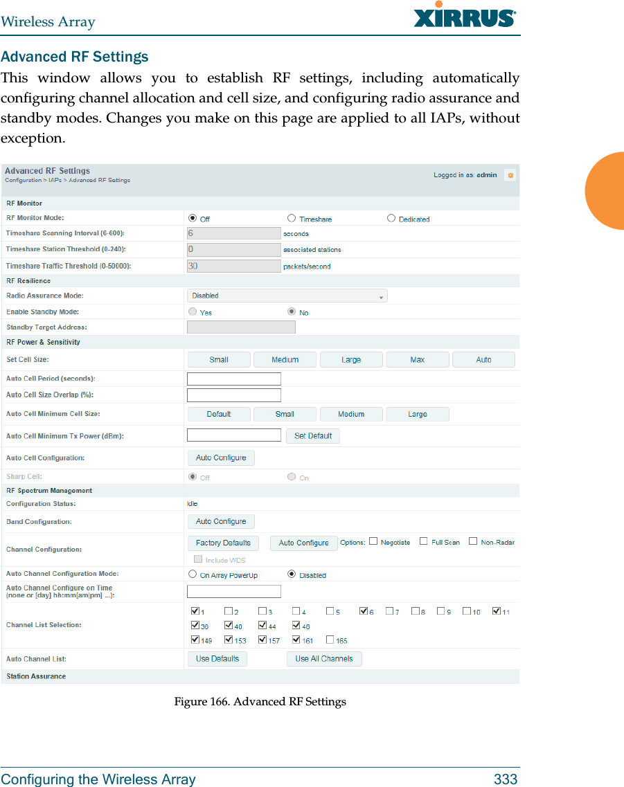
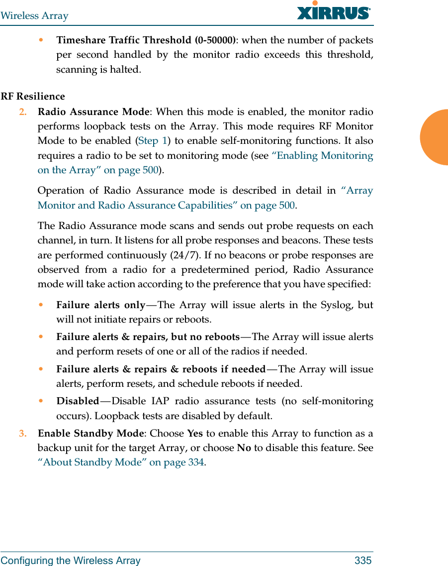
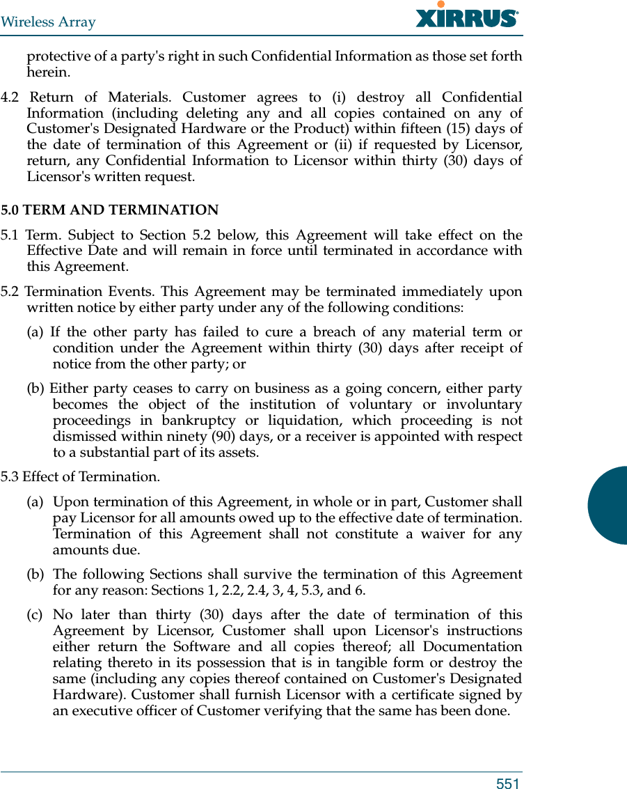
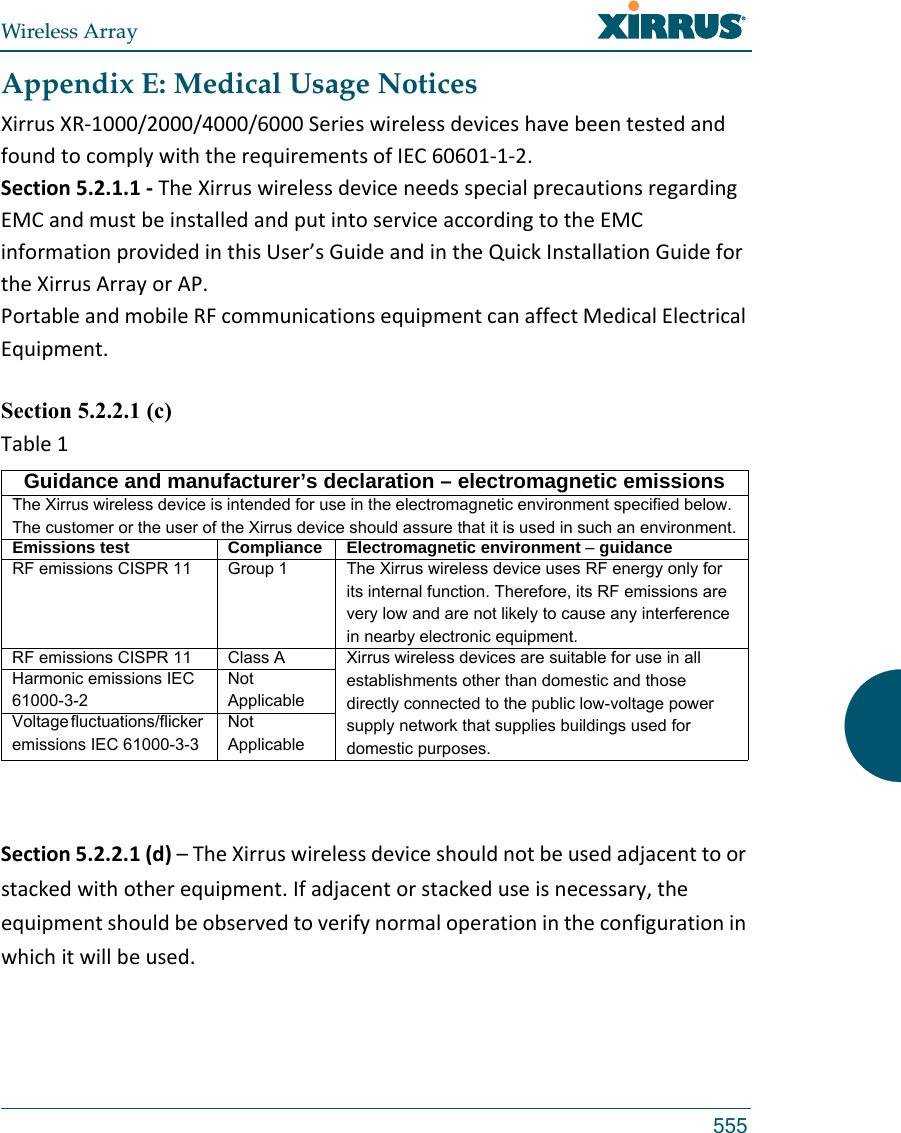
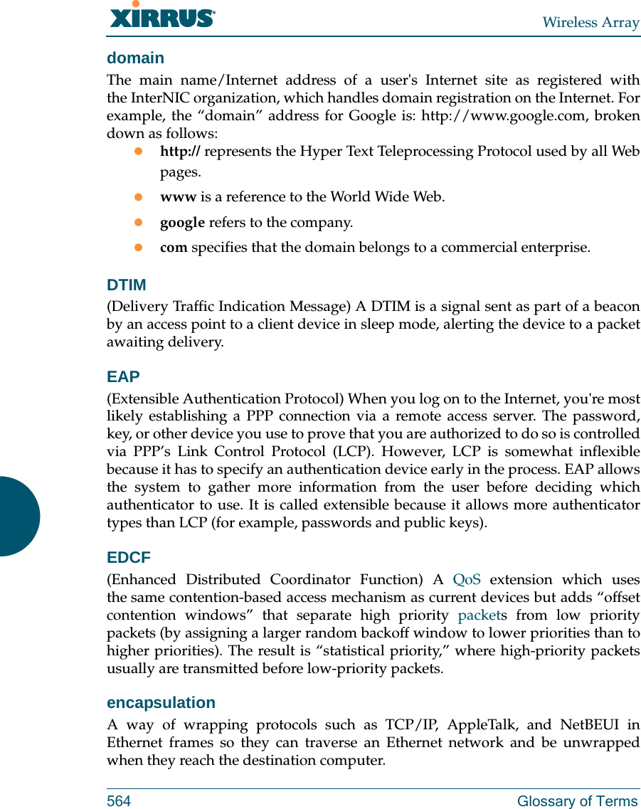
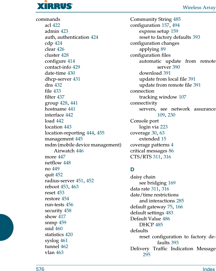
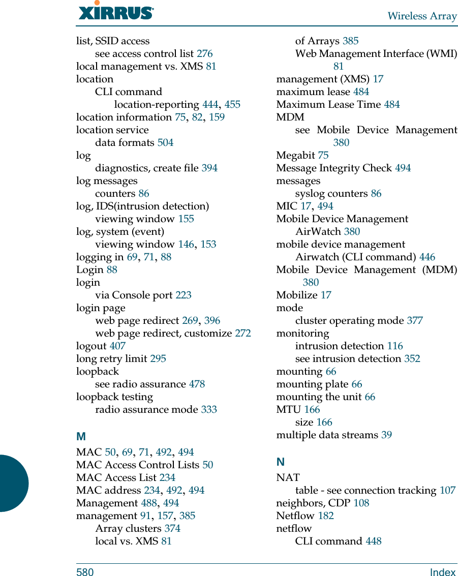
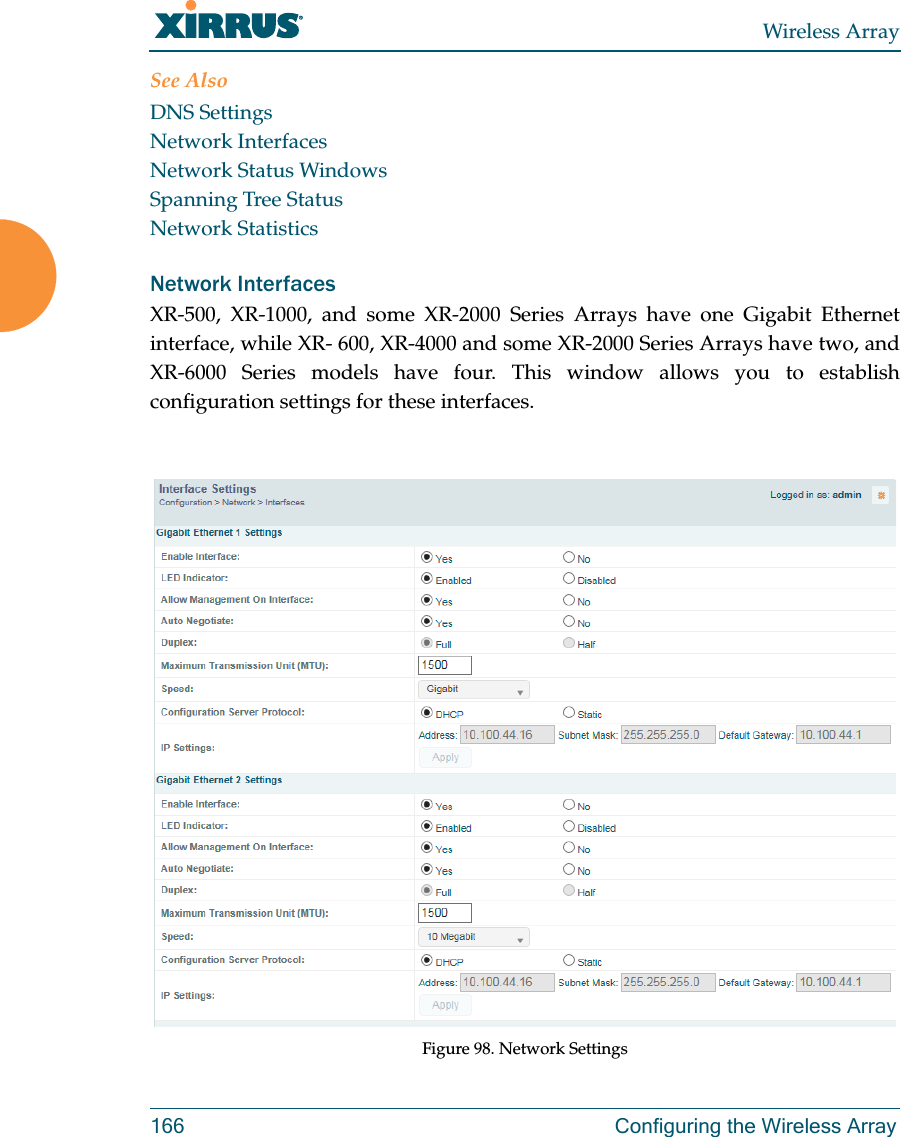
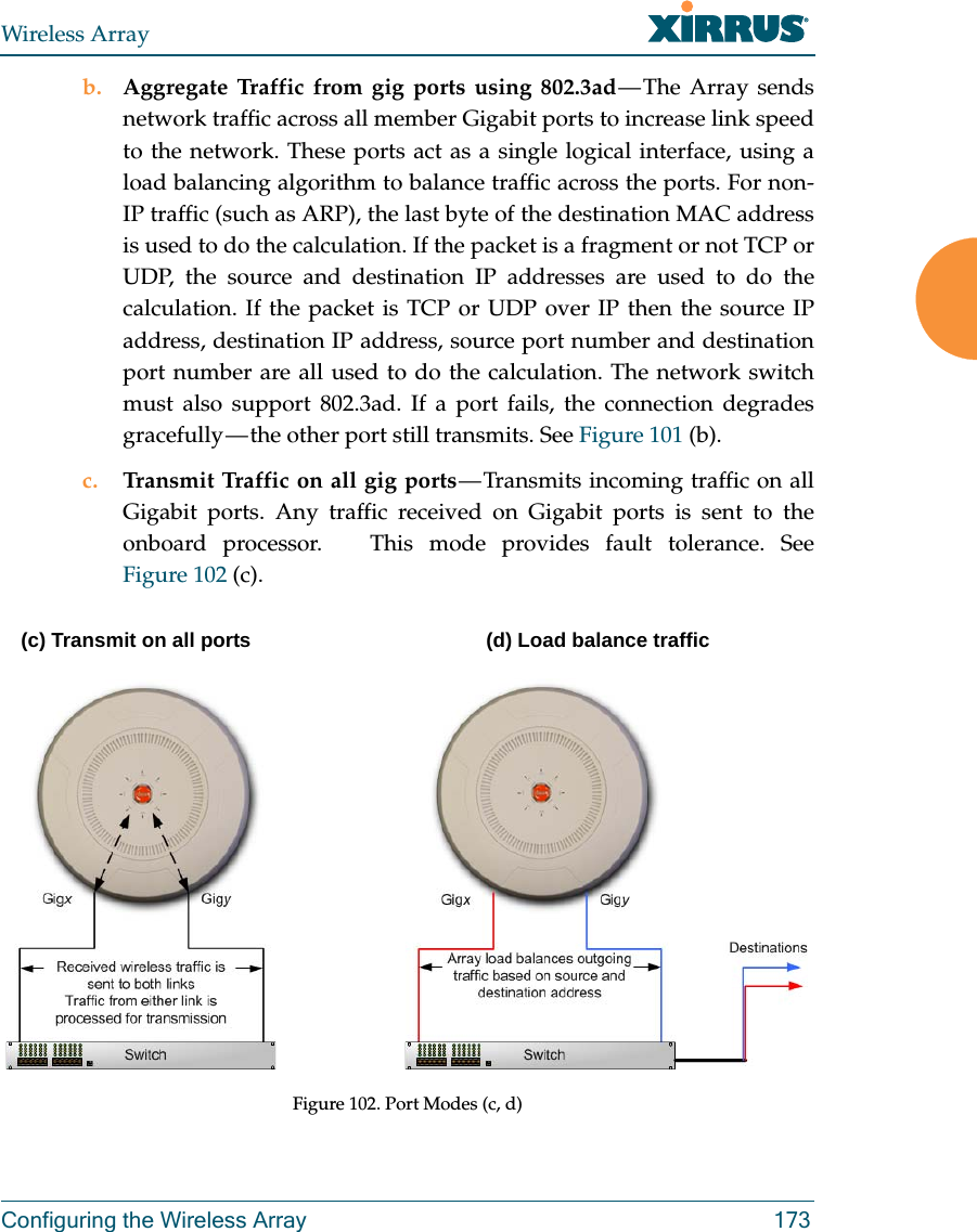
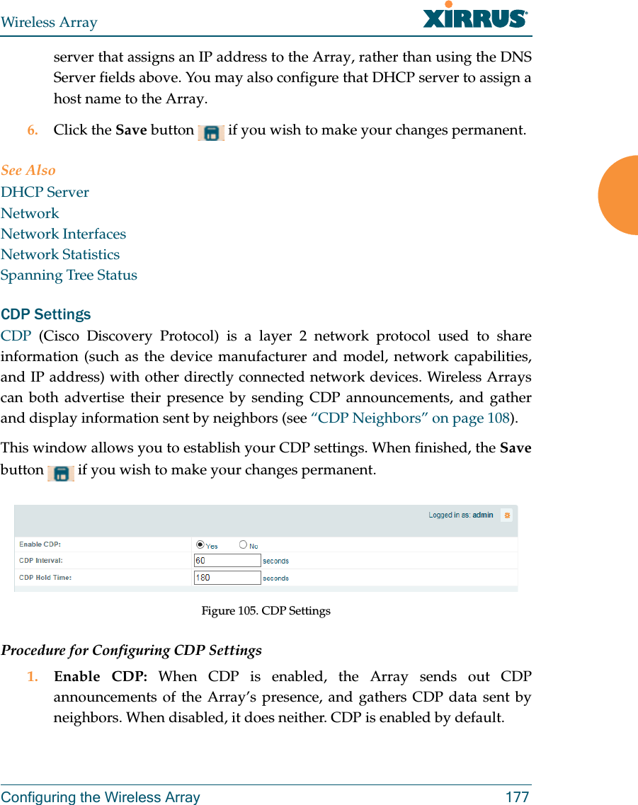
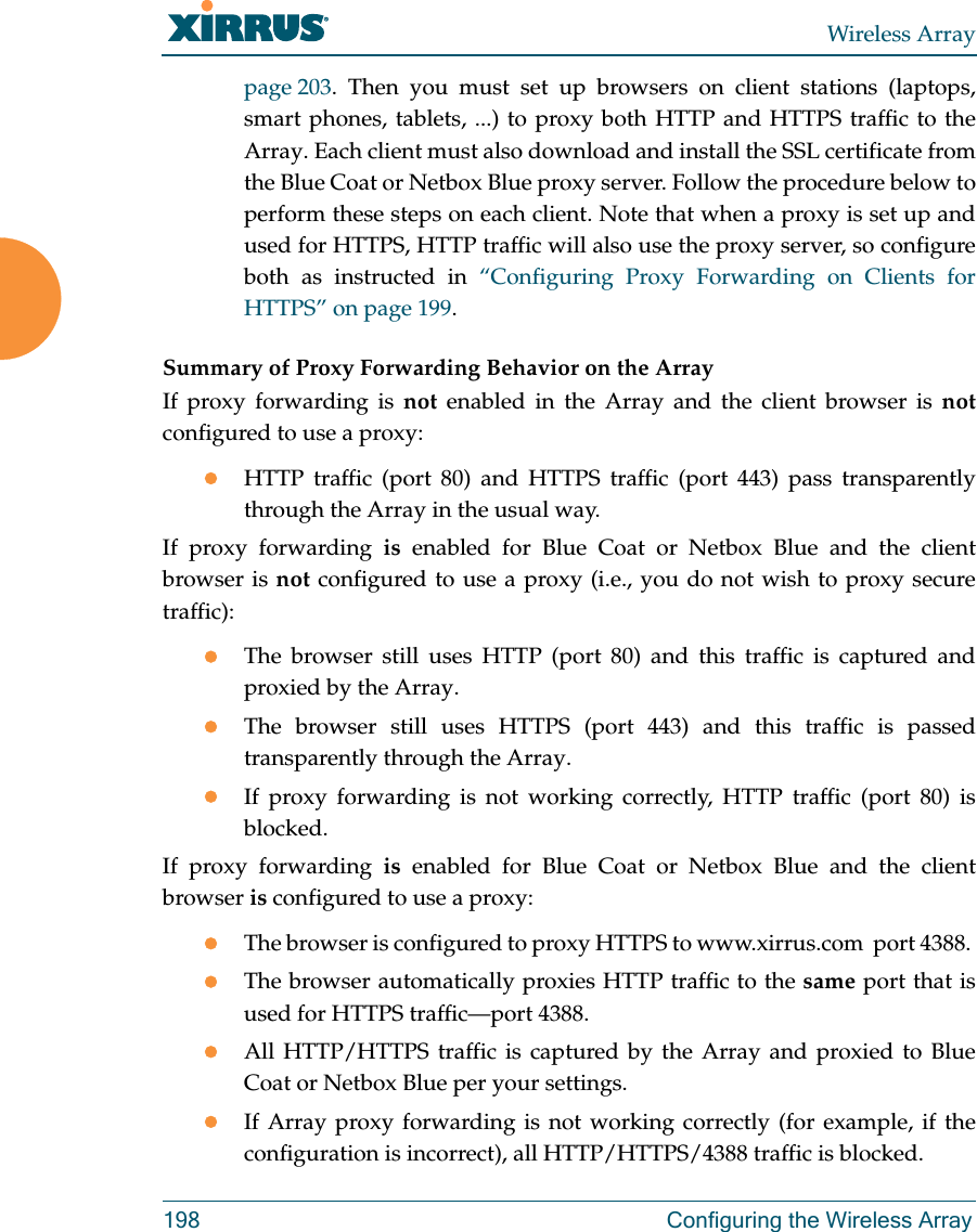
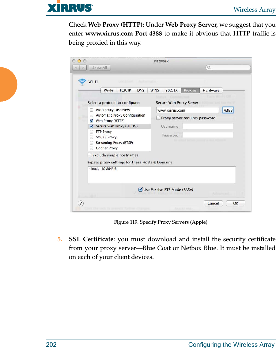
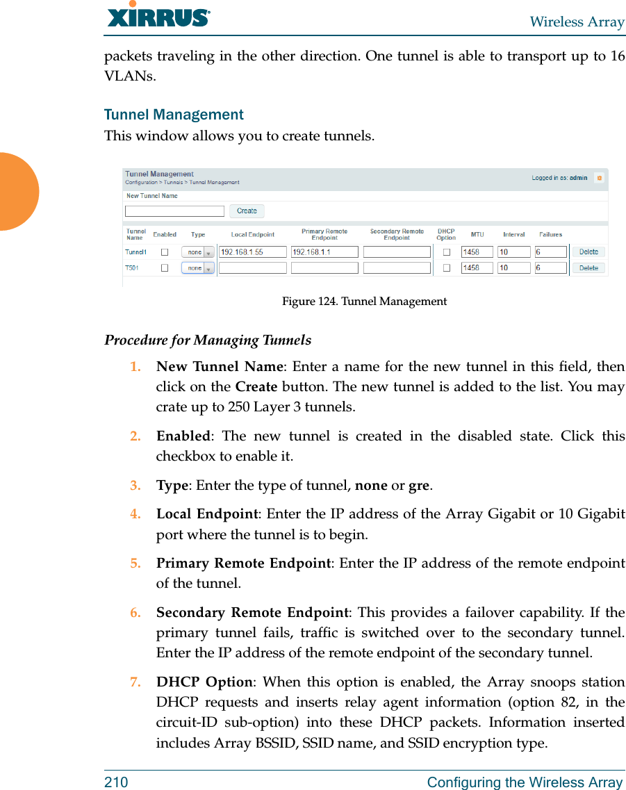
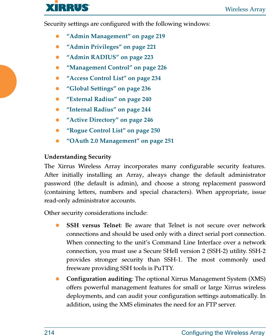
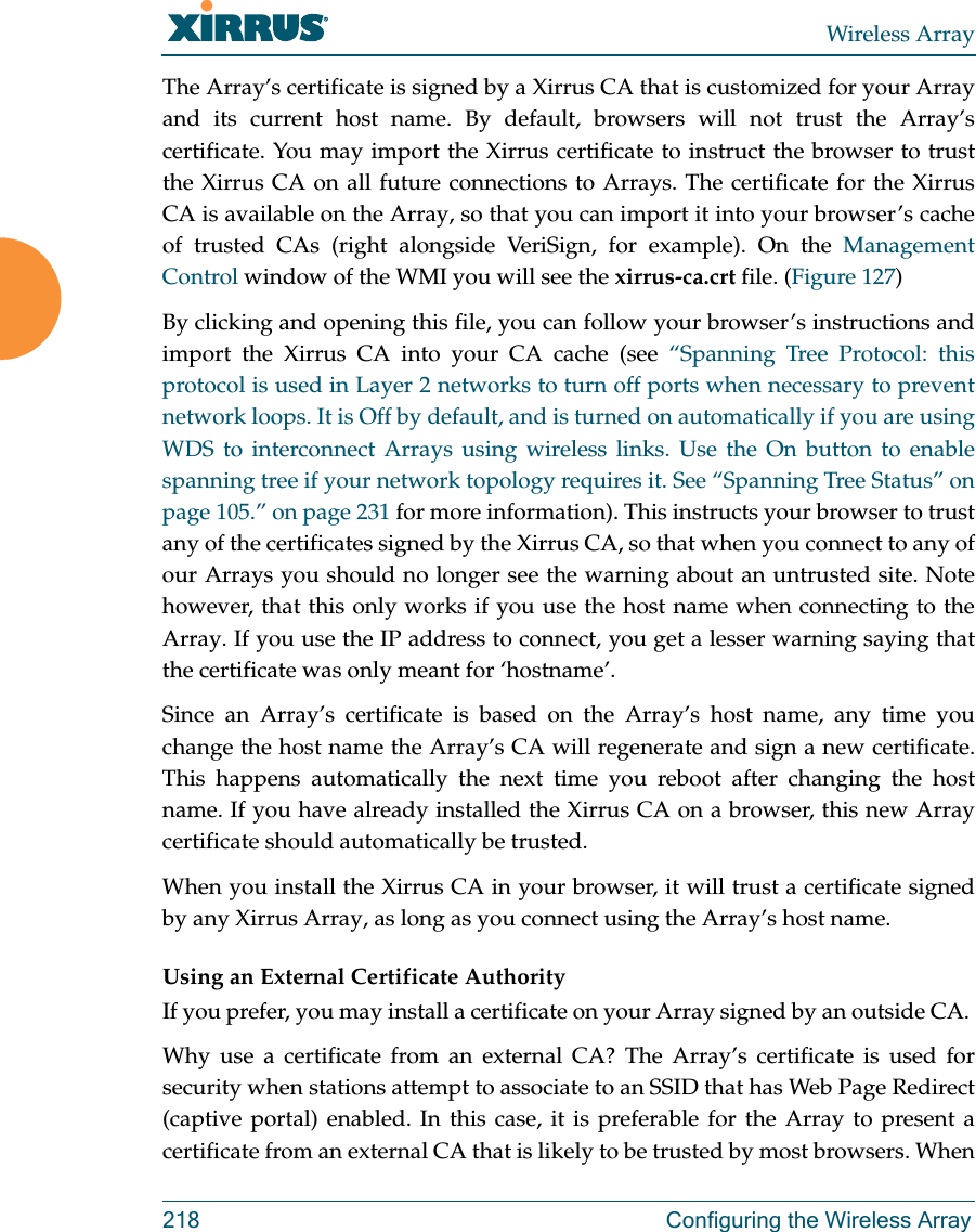
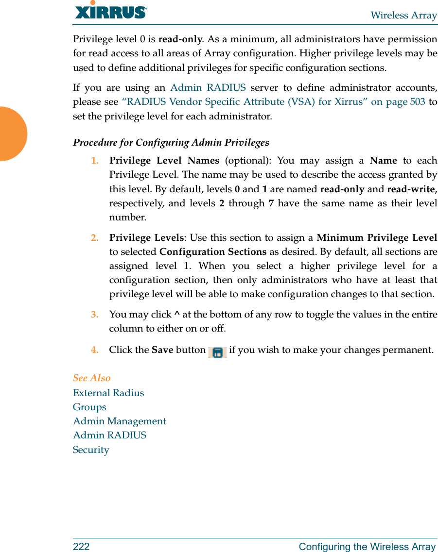
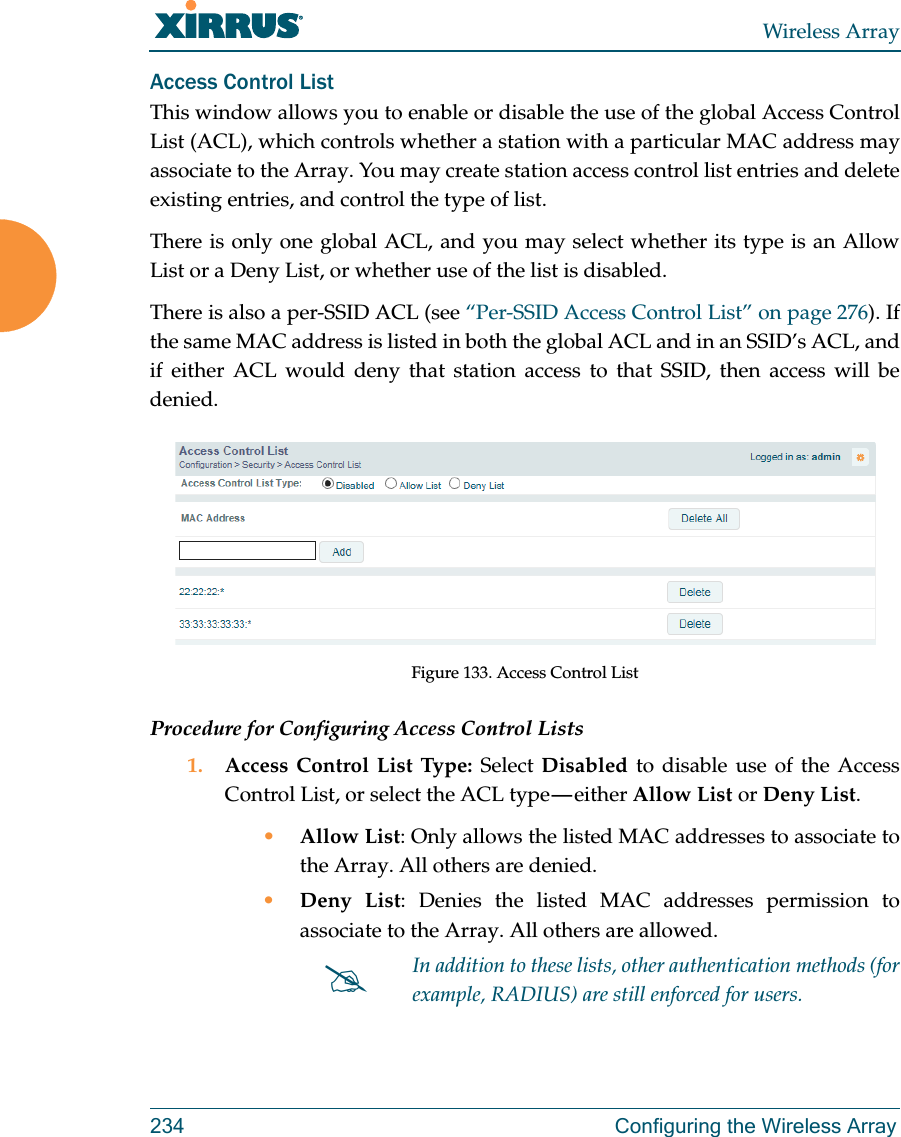
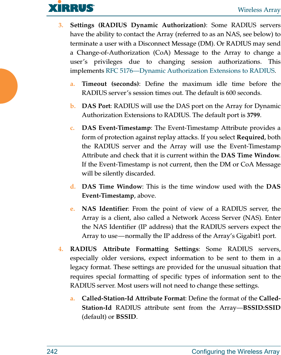
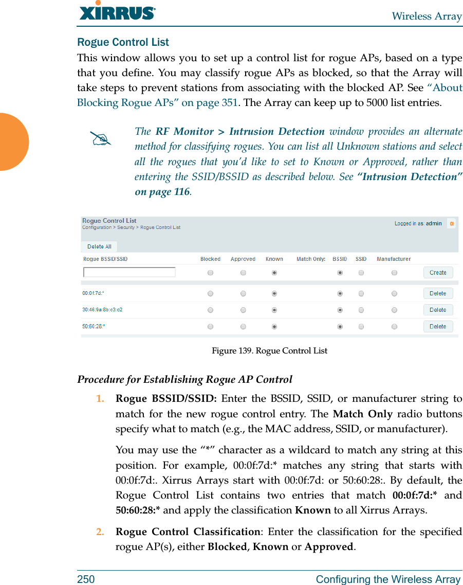
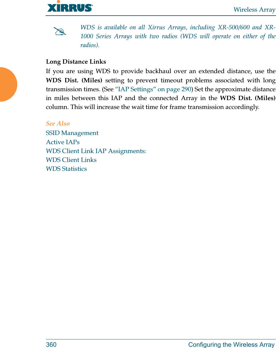
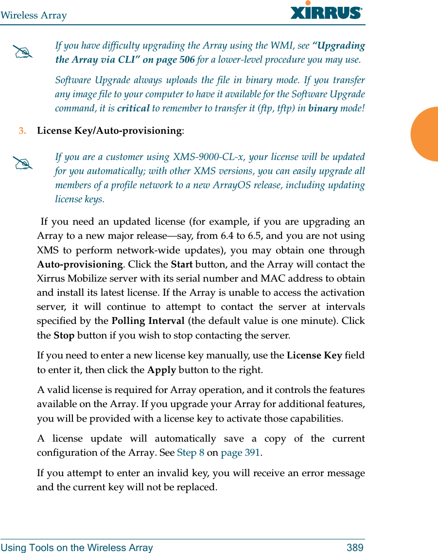
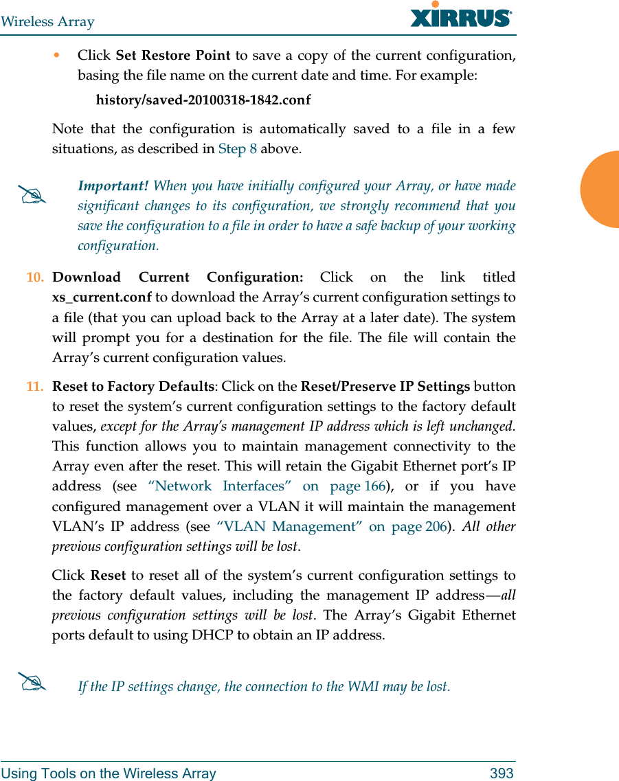
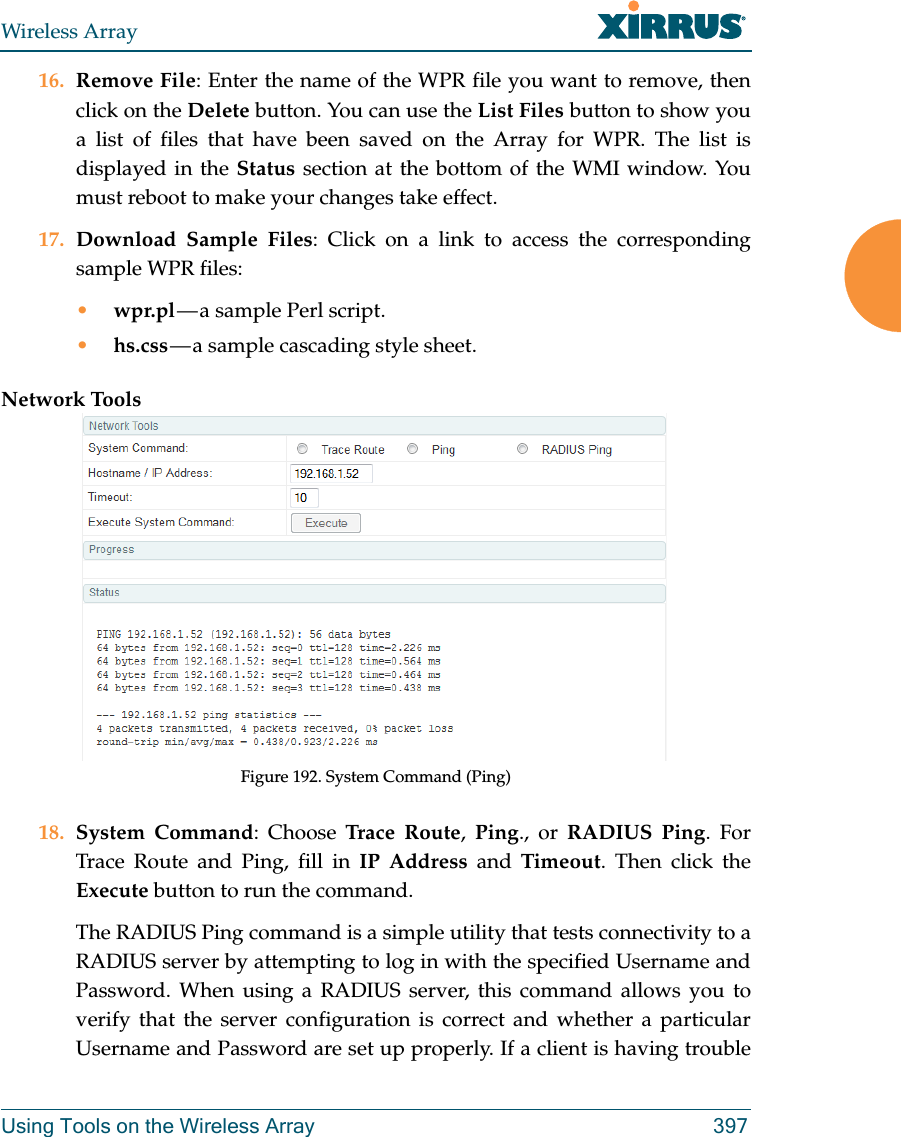
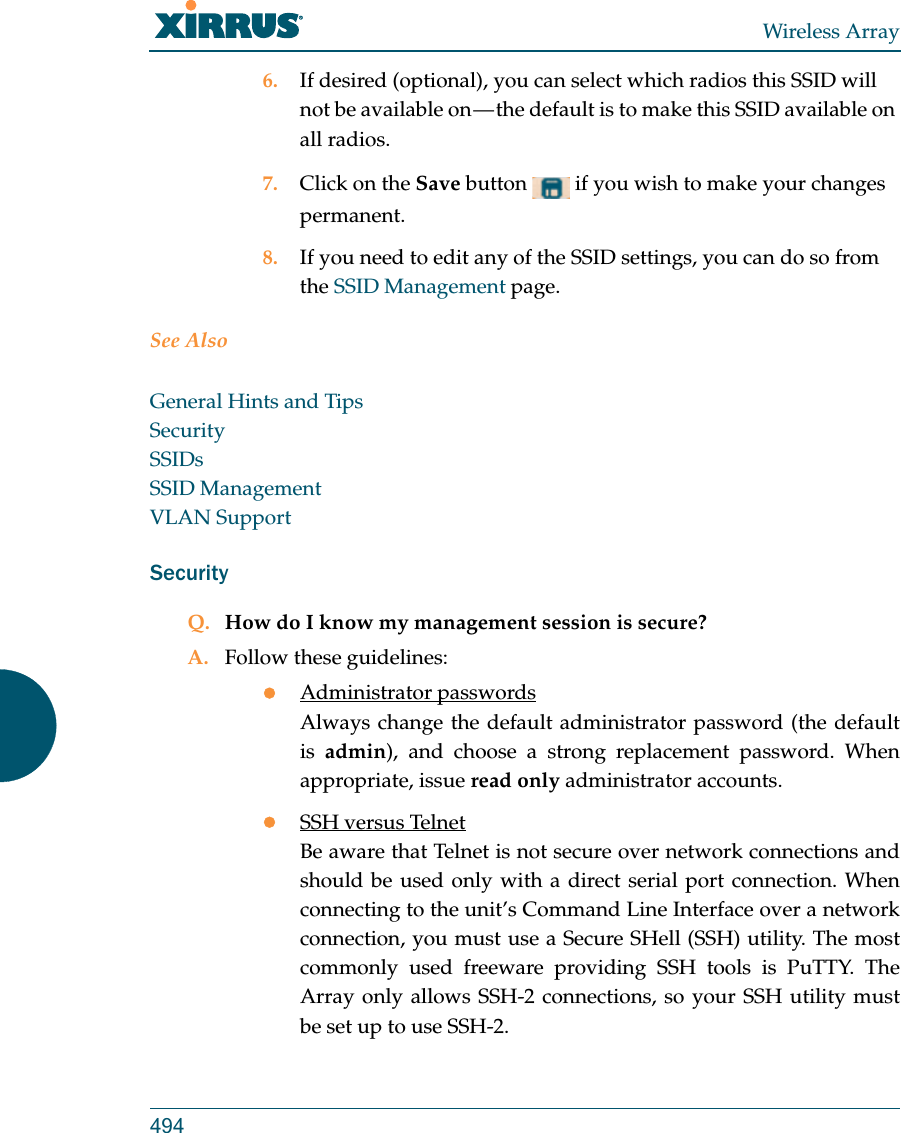
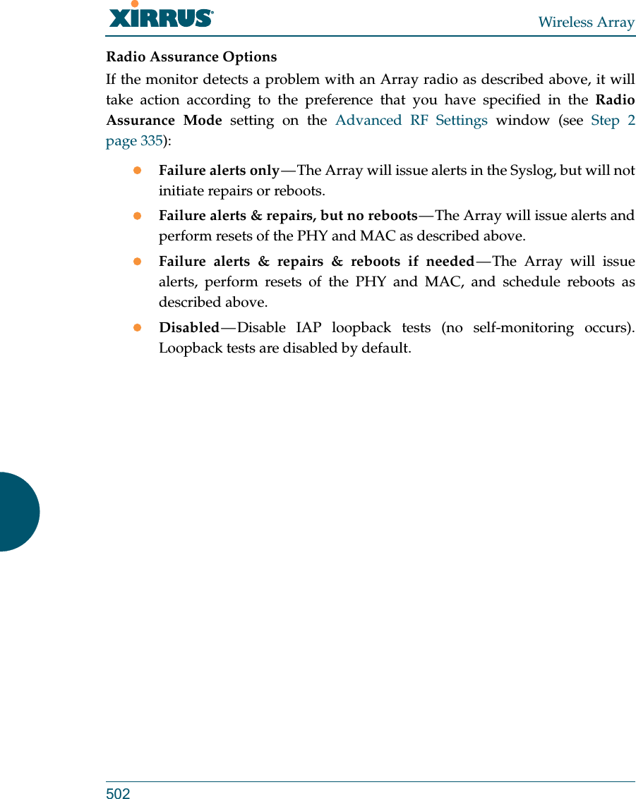
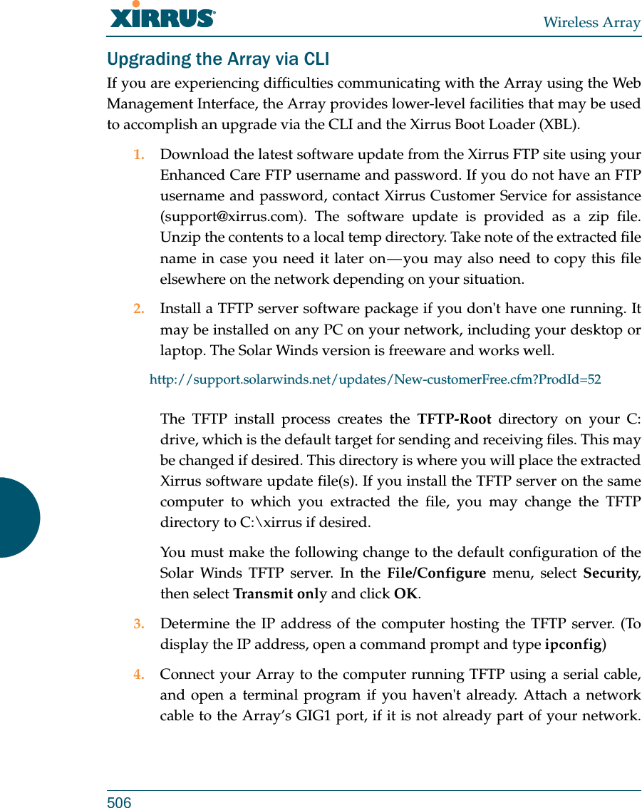
![Wireless ArrayConfiguring the Wireless Array 339channel without waiting, and may be used when you know that no other nearby Arrays are configuring their channels. •Full Scan: perform a full traffic scan on all channels on all IAPs to determine the best channel allocation.•Non-Radar: give preference to channels without radar-detect. See table in “Procedure for Configuring Global 802.11an IAP Settings” on page 311. •Include WDS: automatically assign 5GHz to WDS client links.Click Factory Defaults if you wish to instruct the Array to return all IAPs to their factory preset channels. As of release 6.3, Arrays no longer all use the same factory preset values for channel assignments. Instead, if the Array has been deployed for a while and already has data from the spectrum analyzer and Xirrus Roaming Protocol about channel usage on neighboring Arrays, it performs a quick auto channel using that information (without doing a full RF scan) to make an intelligent choice of channel assignments. If the Array has been rebooted and has no saved configuration or is just being deployed for the first time, it has no prior data about its RF environment. In this case, it will pick a set of compatible channel assignments at random. 15. Auto Channel Configuration Mode: This option allows you to instruct the Array to auto-configure channel selection for each enabled IAP when the Array is powered up. Choose On Array PowerUp to enable this feature, or choose Disabled to disable this feature.16. Auto Channel Configure on Time: This option allows you to instruct the Array to auto-configure channel selection for each enabled IAP at a time you specify here. Leave this field blank unless you want to specify a time at which the auto-configuration utility is initiated. Time is specified in hours and minutes, using the format: [day]hh:mm [am|pm]. If you omit On XR-500/600 and XR-1000 Series Arrays, the Factory Defaults button will not restore iap1 to monitor mode. You will need to restore this setting manually. Also, you may need to set RF Monitor Mode to Timeshare Mode again - see “RF Monitor” on page 334.](https://usermanual.wiki/Cambium-Networks/XI-AC1300.Part-2/User-Guide-2284763-Page-183.png)
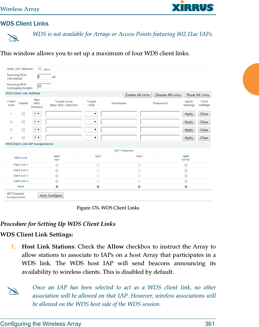

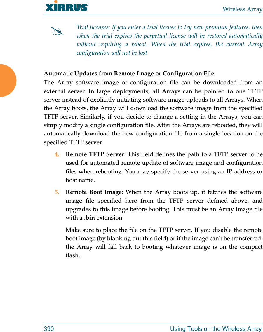
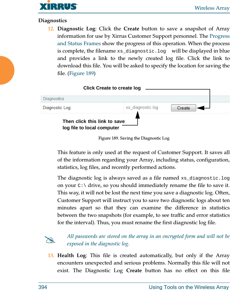
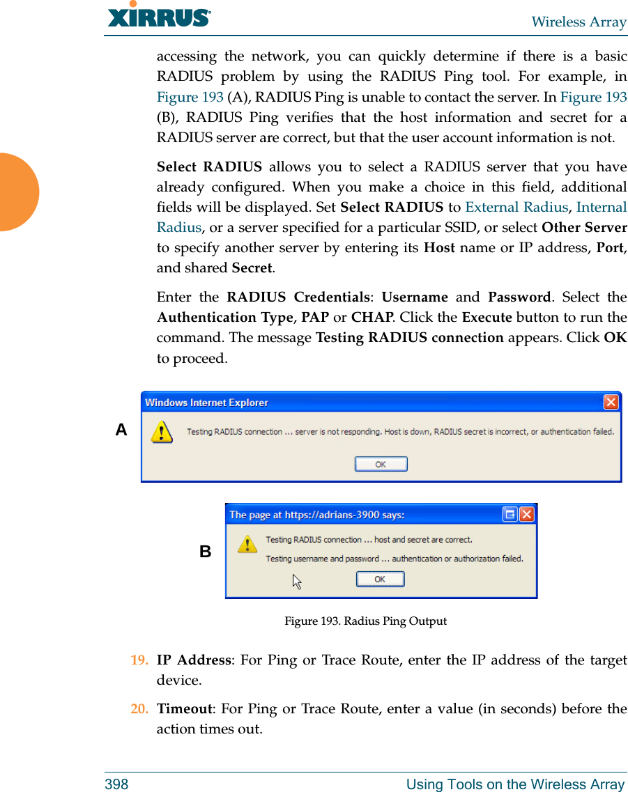
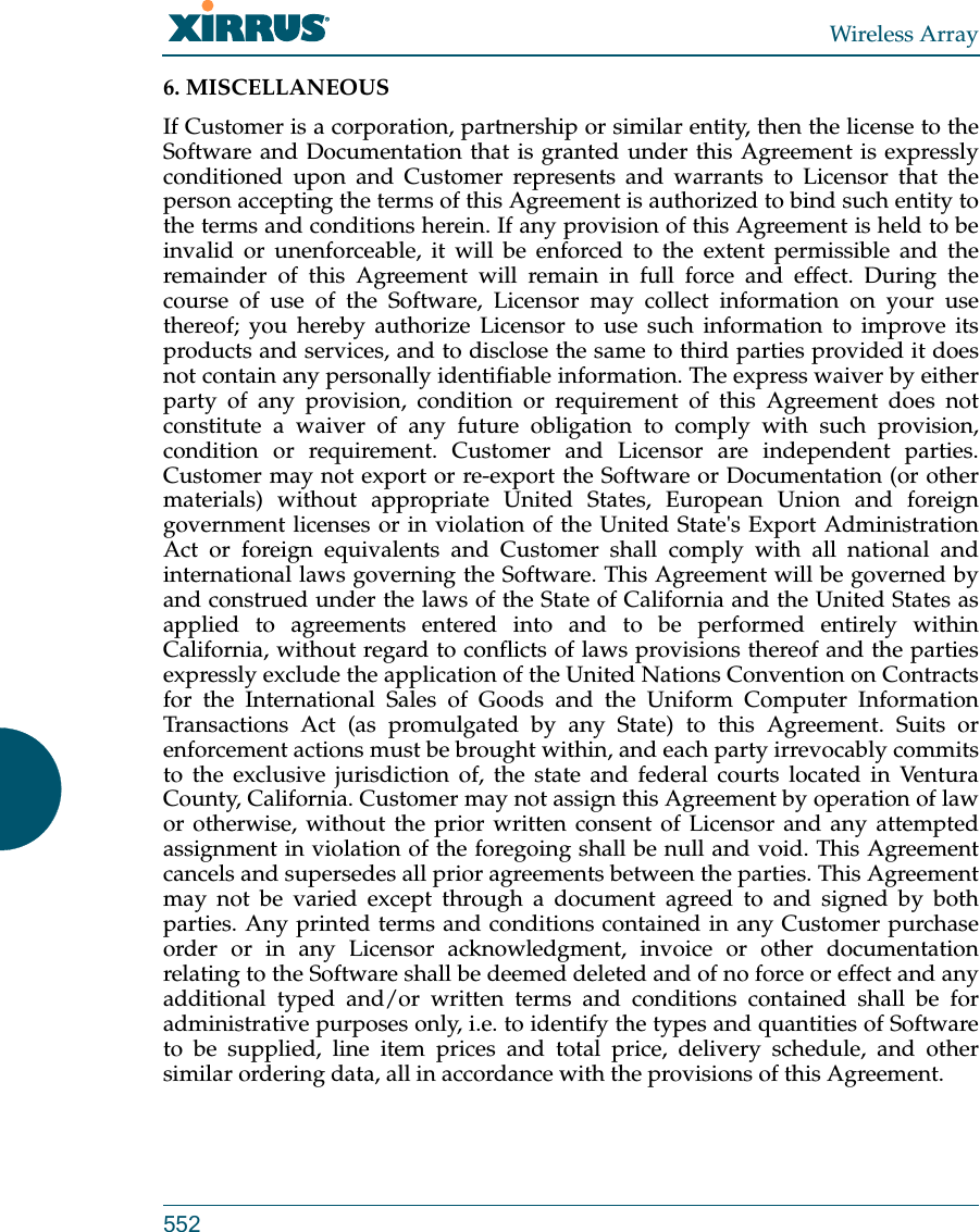
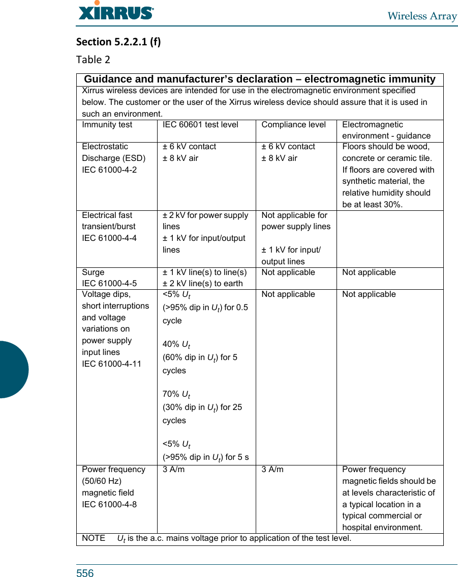
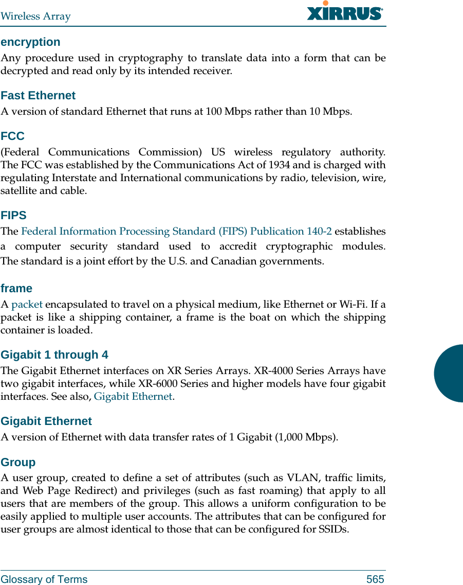
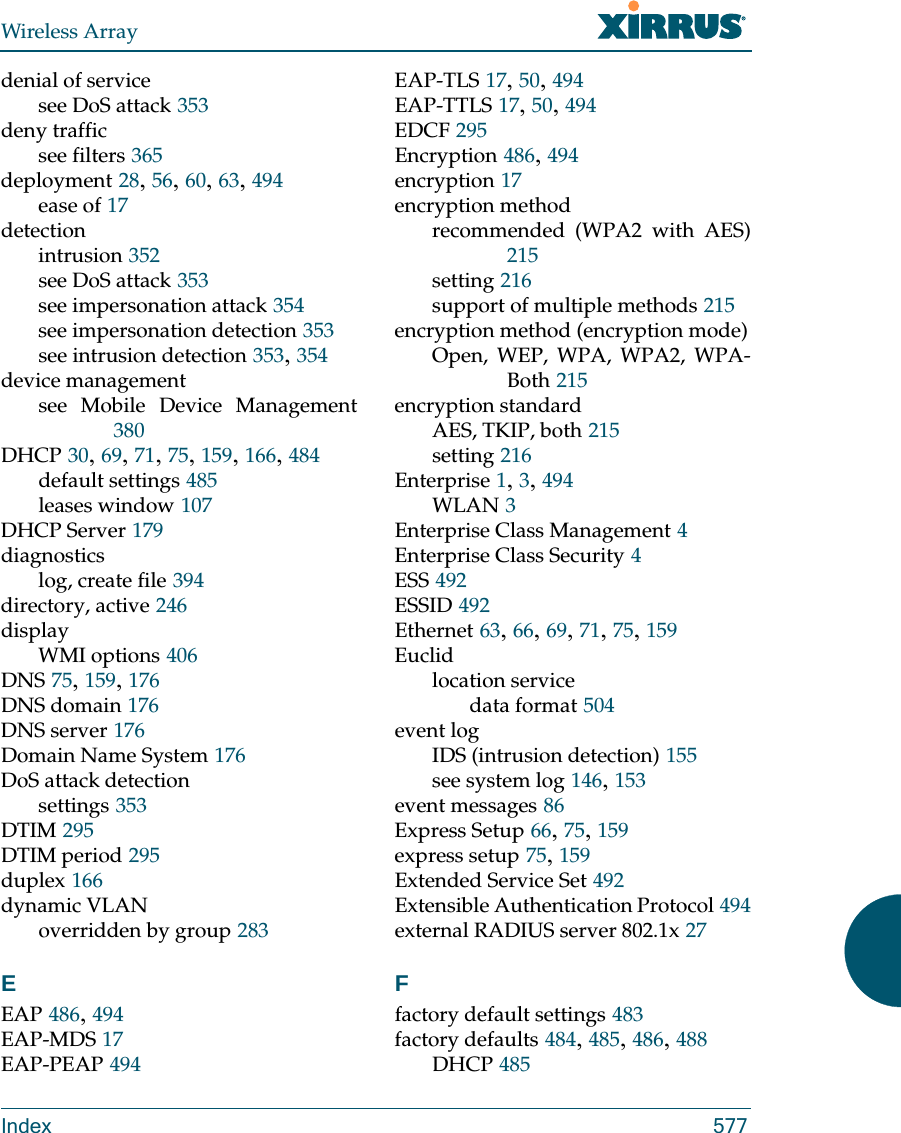
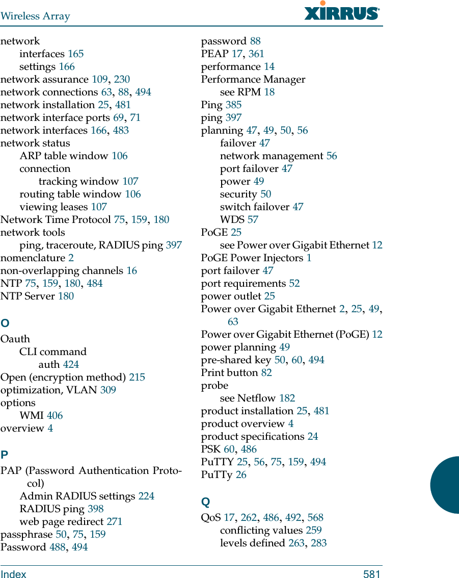
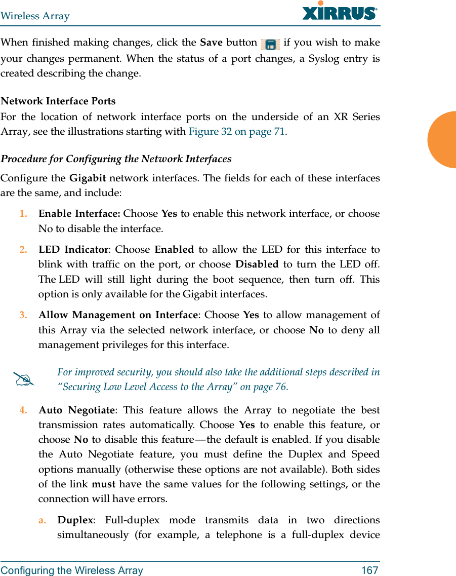
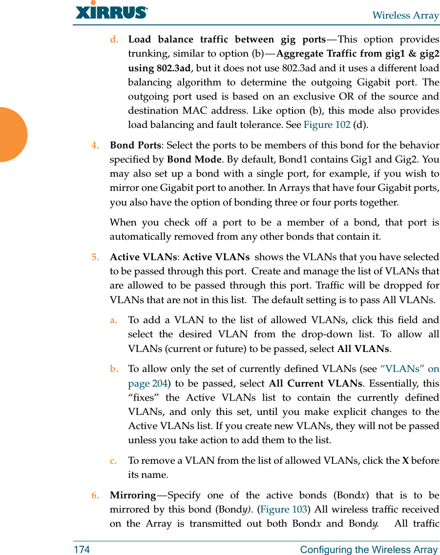
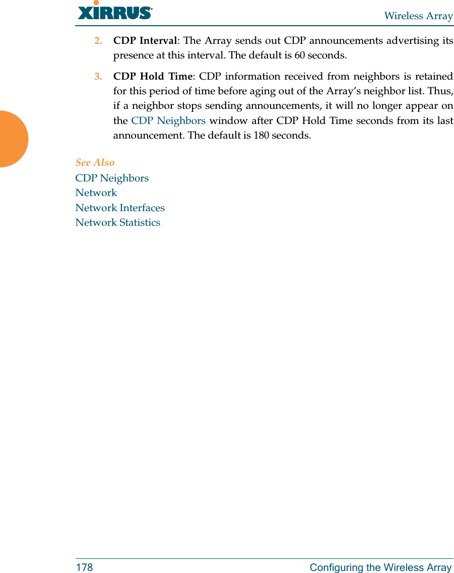
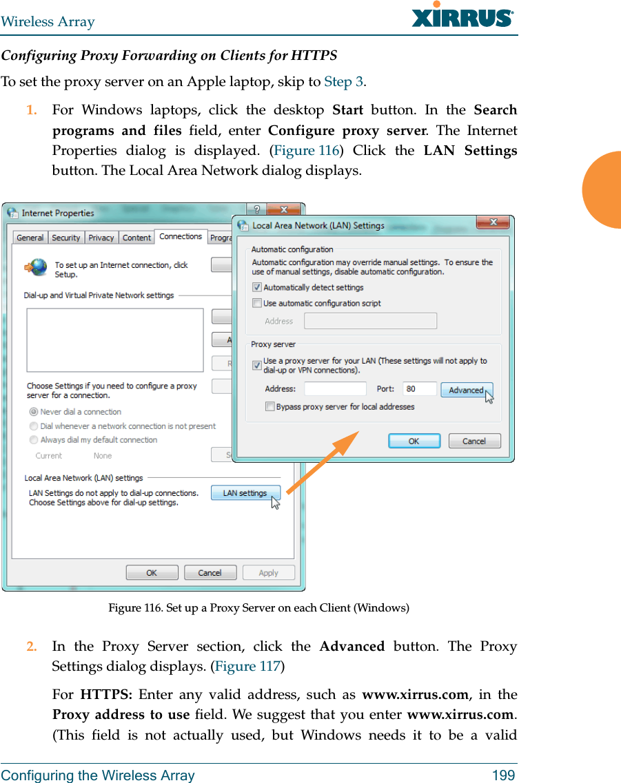
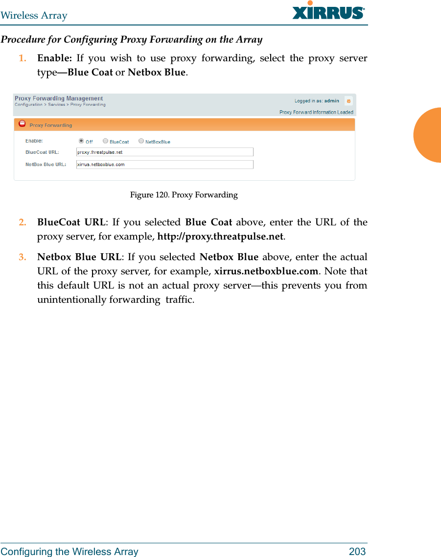
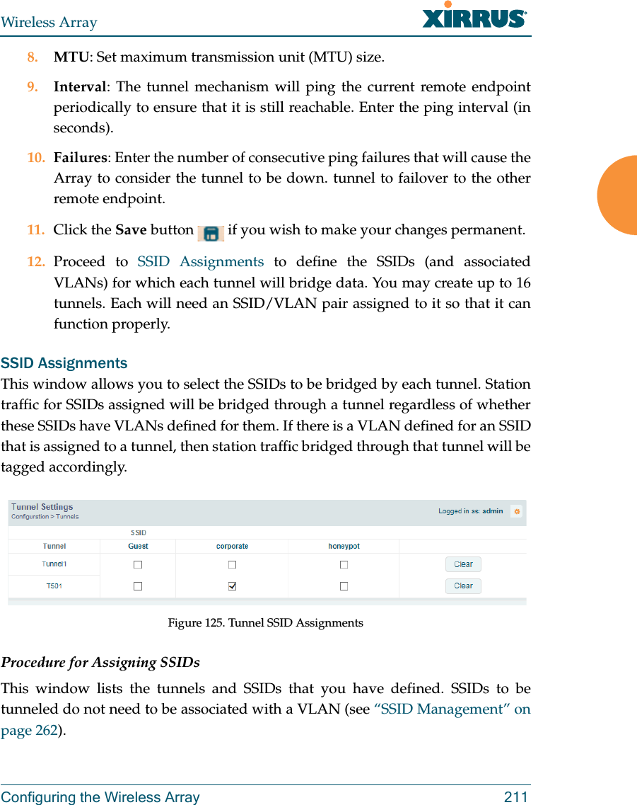
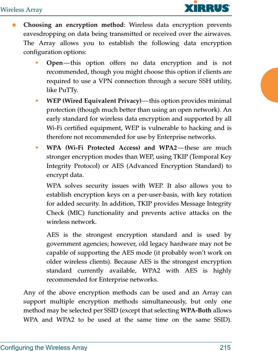
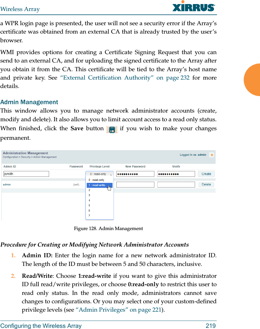
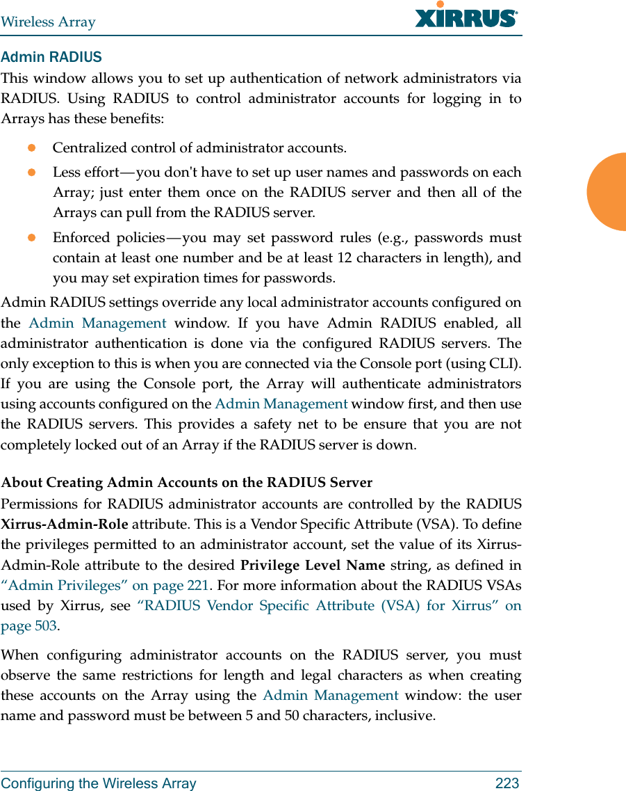
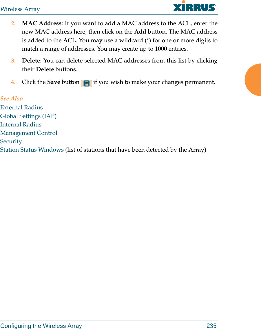
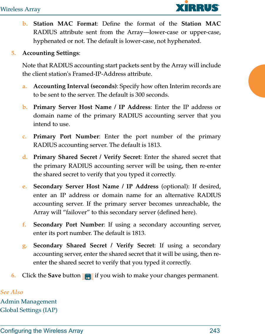
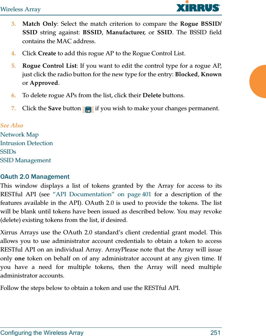
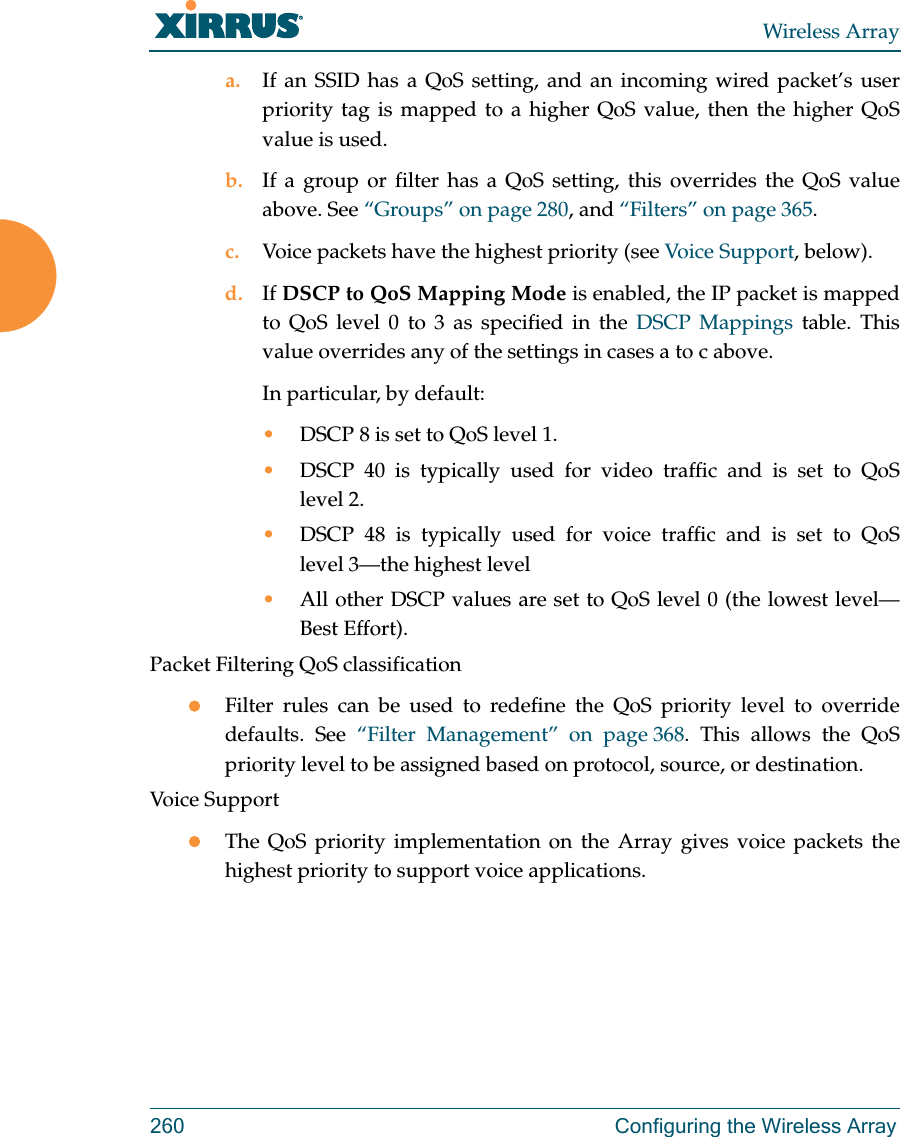
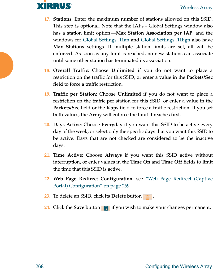
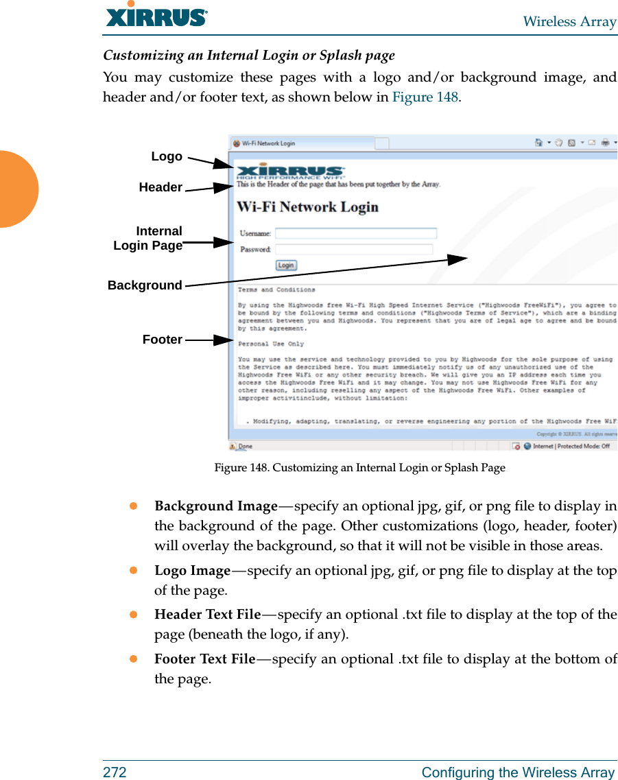
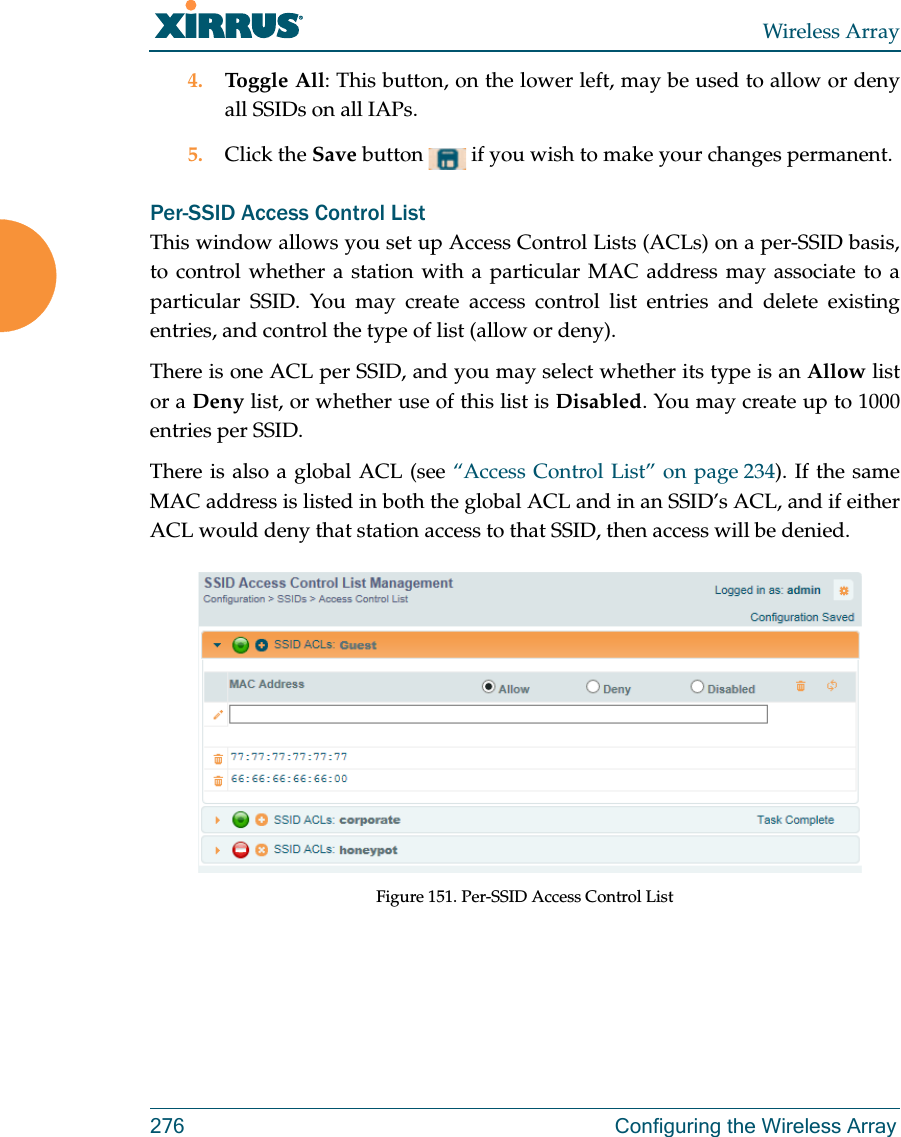
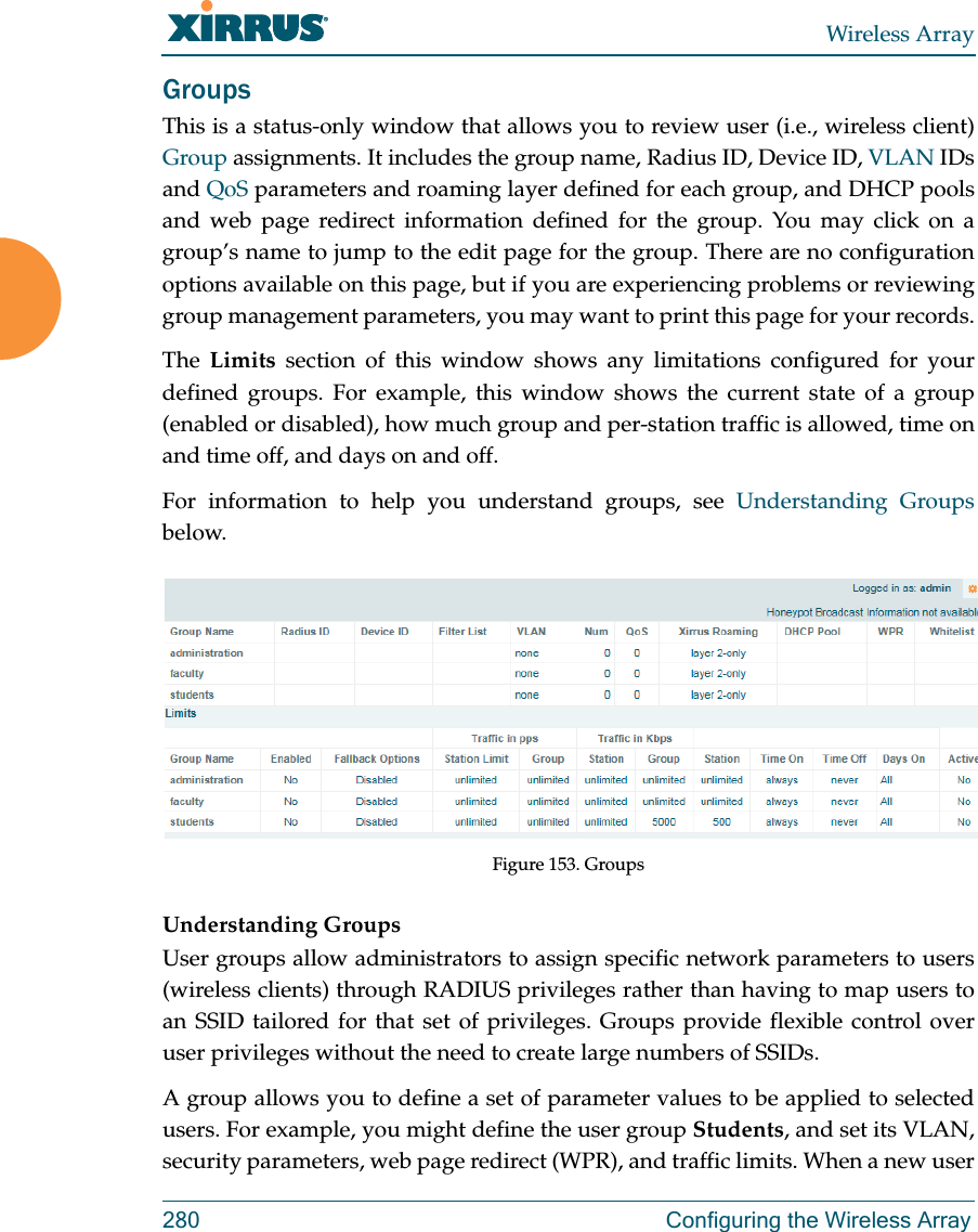
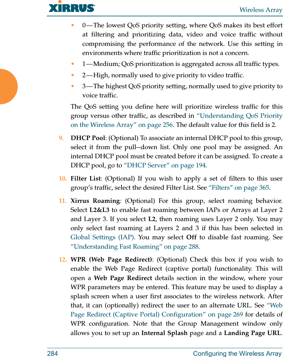
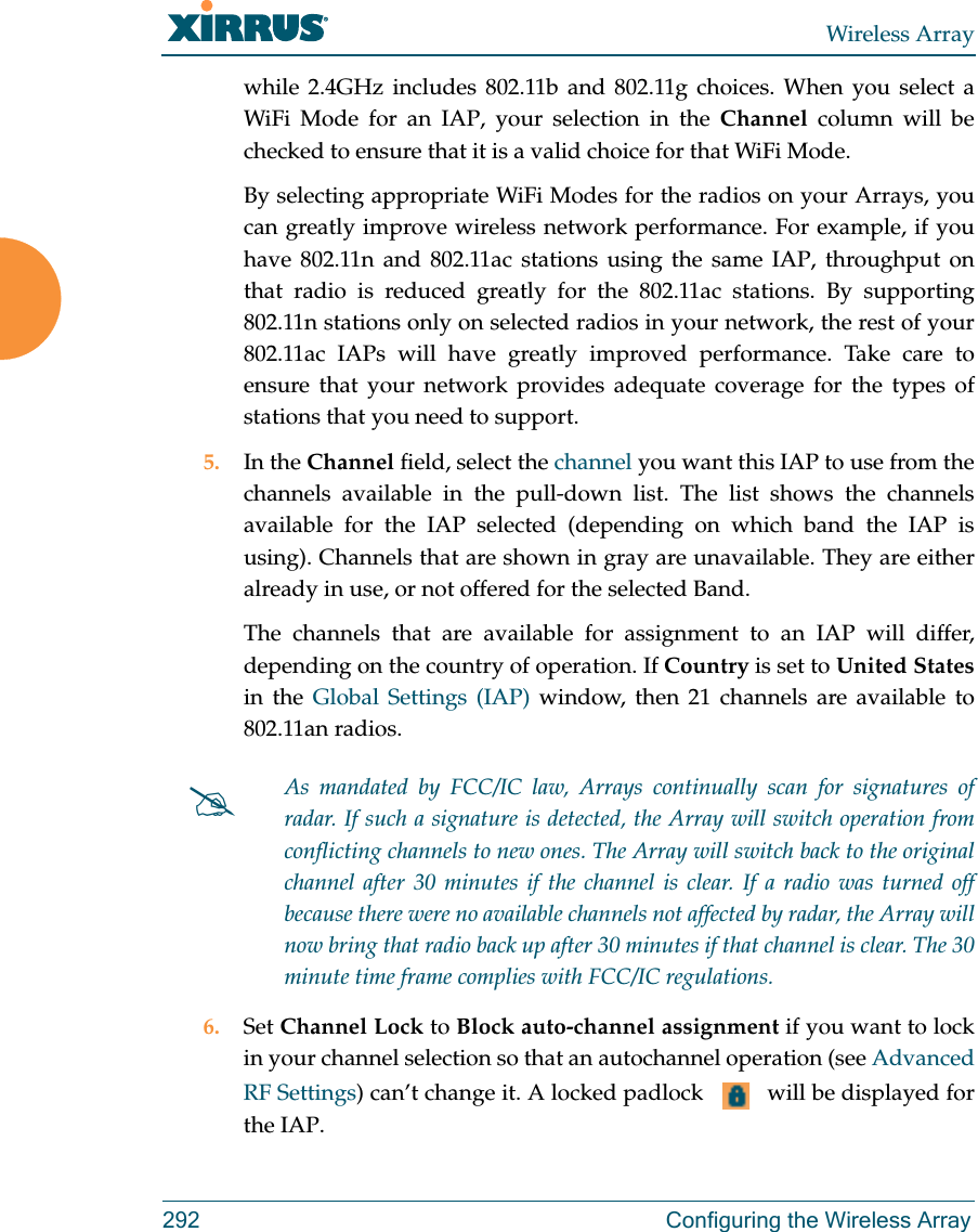
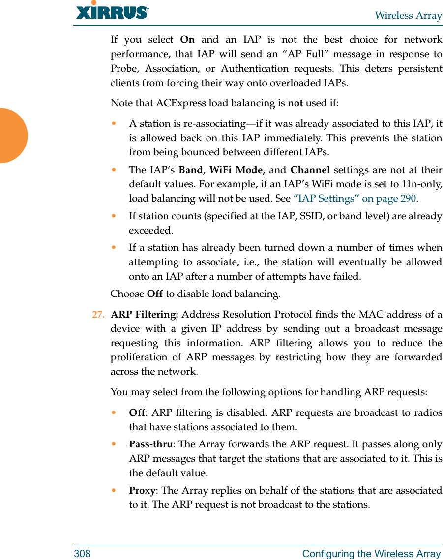
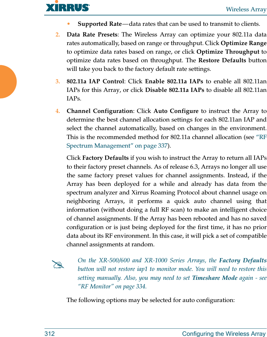
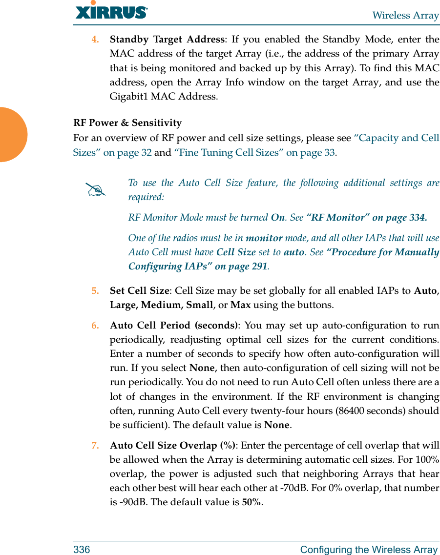
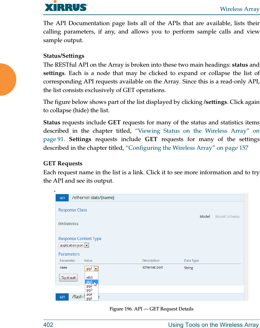
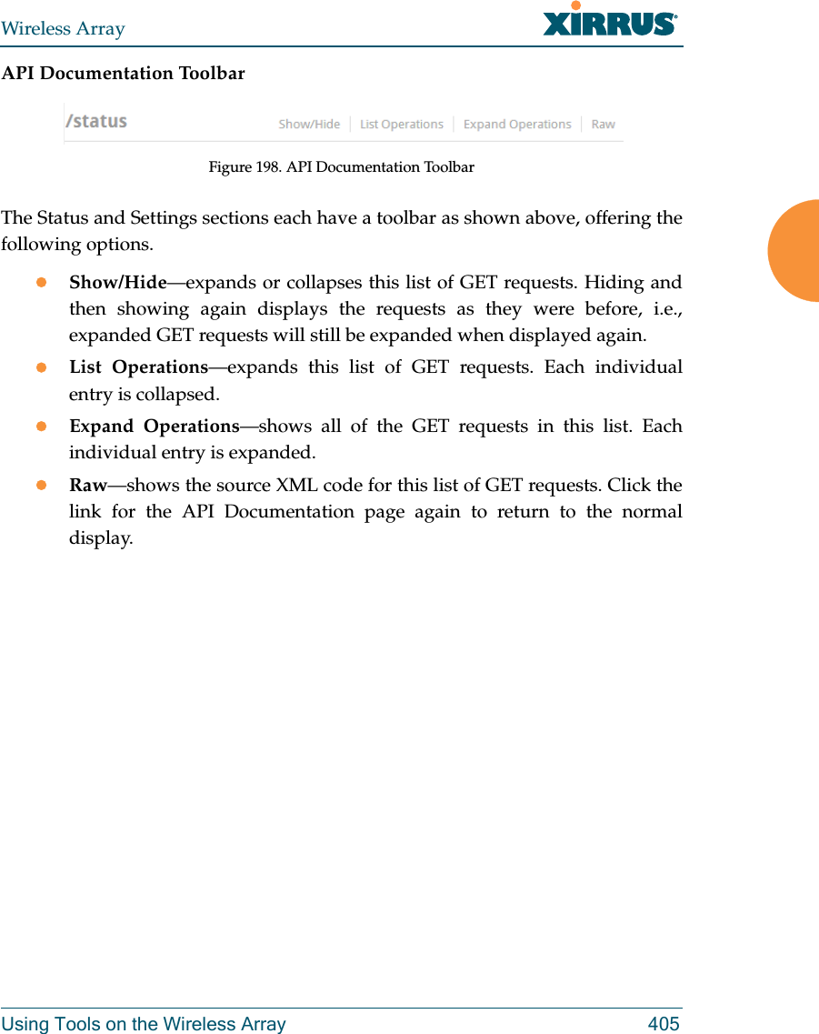
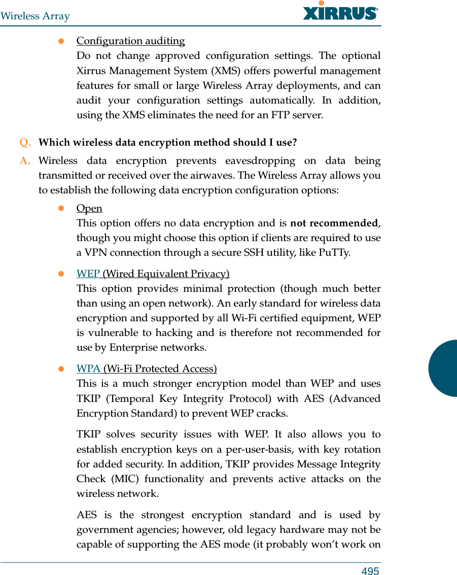
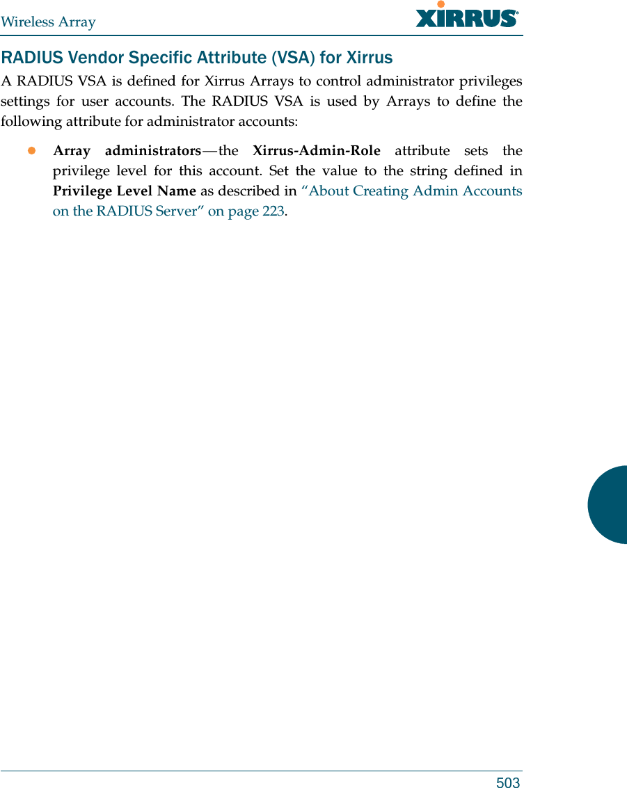
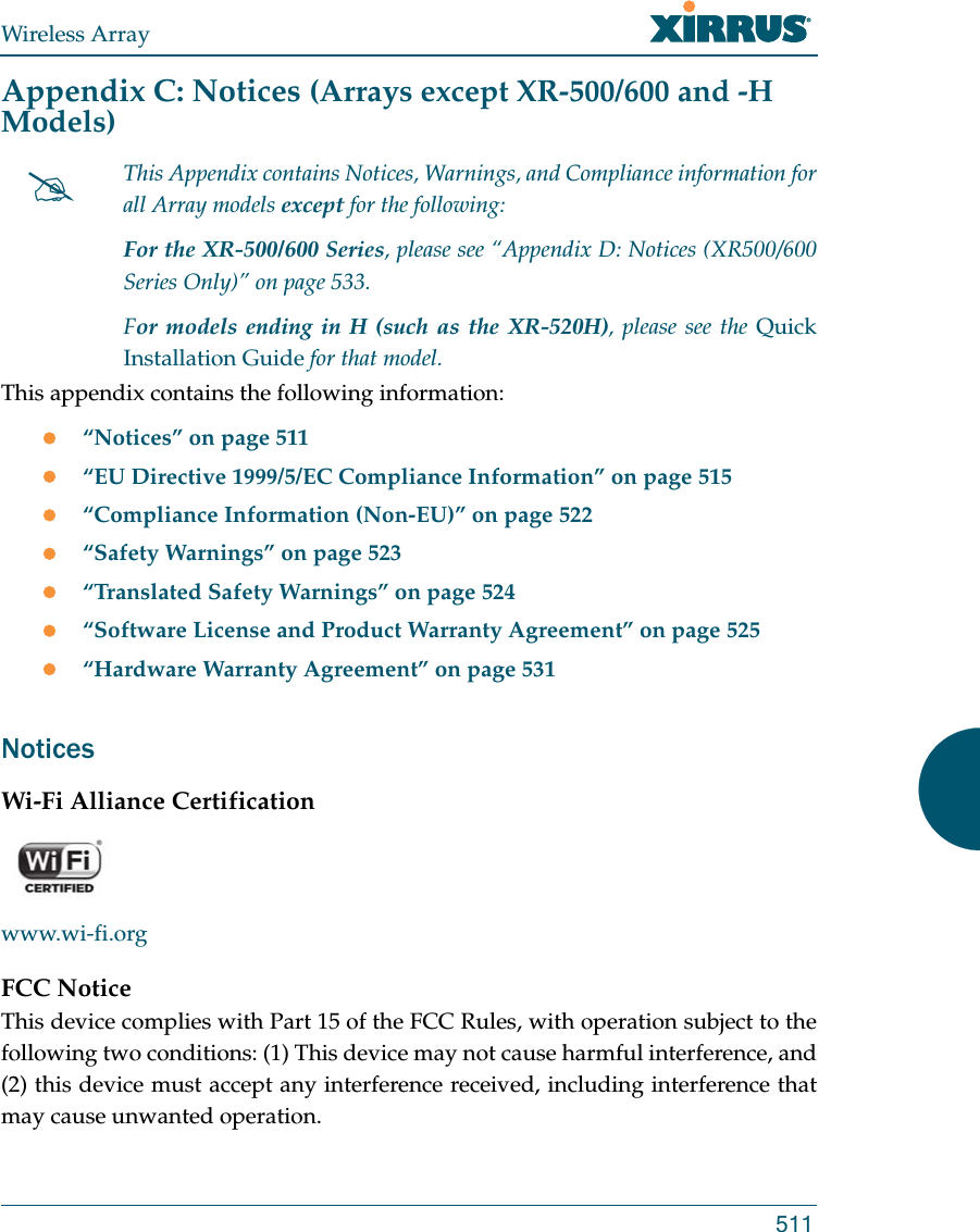
![Wireless ArrayUsing Tools on the Wireless Array 401API DocumentationArrays provide an API interface conforming to the RESTful API model. Developers may use this read-only API to read status, statistics, and settings from the Array. The interactive API Documentation page provides documentation for the API. You may use the Array’s API for purposes such as integrating with third party applications or creating your own applications for network monitoring and analysis. Using the RESTful API eliminates the need to use CLI scripting, or to use SNMP which can be cumbersome for polling large amounts of data. Results are returned in JSON format (JavaScript Object Notation), a text-based open standard designed for human-readable data interchange. The API documentation is tightly integrated with the server code. The API Documentation page allows you to interact with the API in a sandbox UI that gives clear insight into how the API responds to parameters and options. Security for the API is provided with OAuth, as described in “OAuth 2.0 Management” on page 251. Once registration is completed and a permanent token for this Array has been obtained, your application may access the RESTful API using the client_id and the token at the following URL: https://[Array hostname or IP address]/api/v1/[api-name] Figure 195. API Documentation](https://usermanual.wiki/Cambium-Networks/XI-AC1300.Part-2/User-Guide-2284763-Page-245.png)

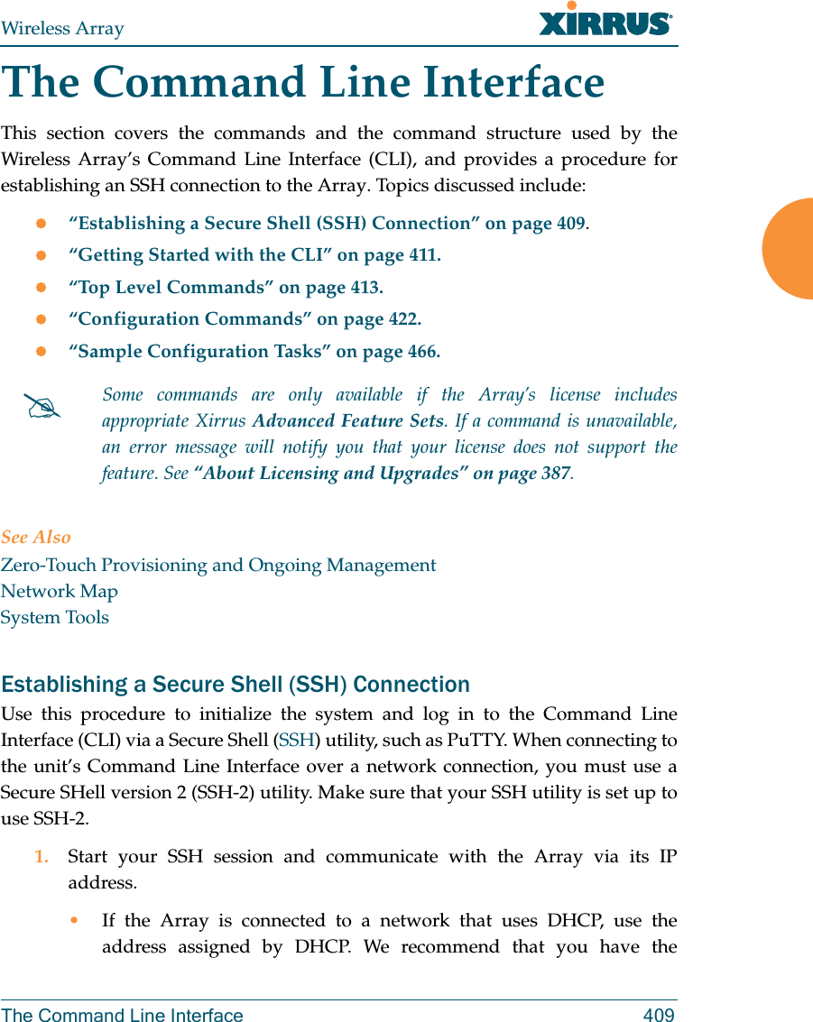
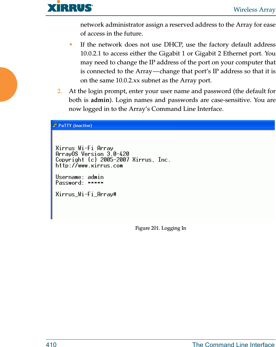

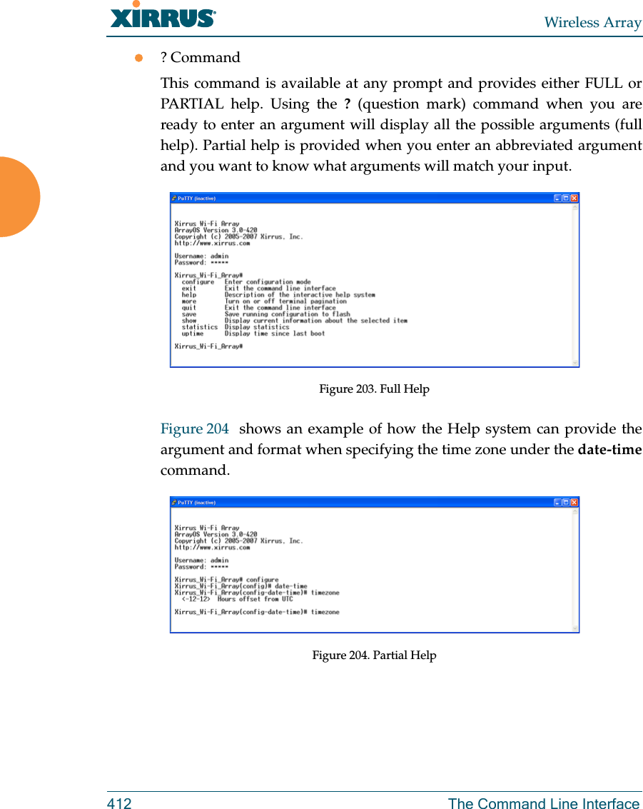
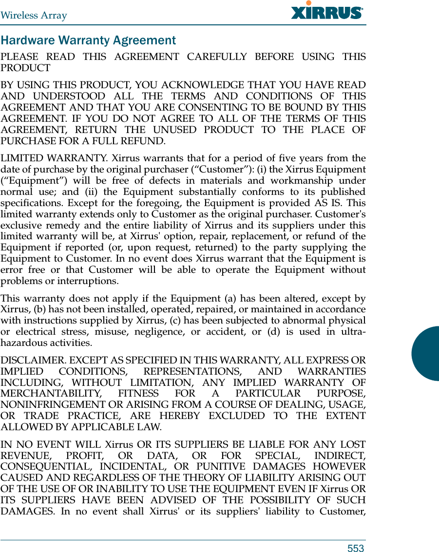
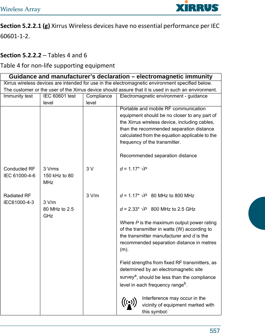
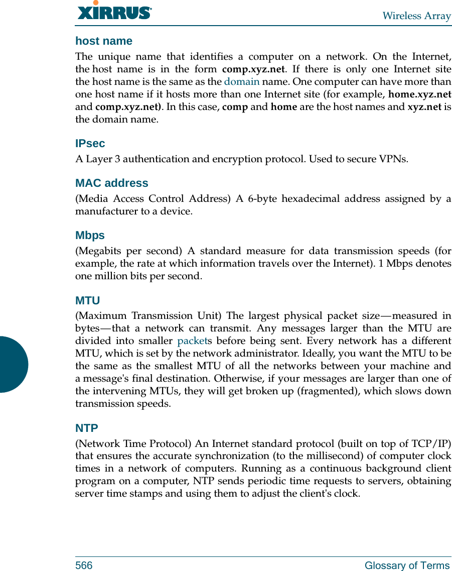
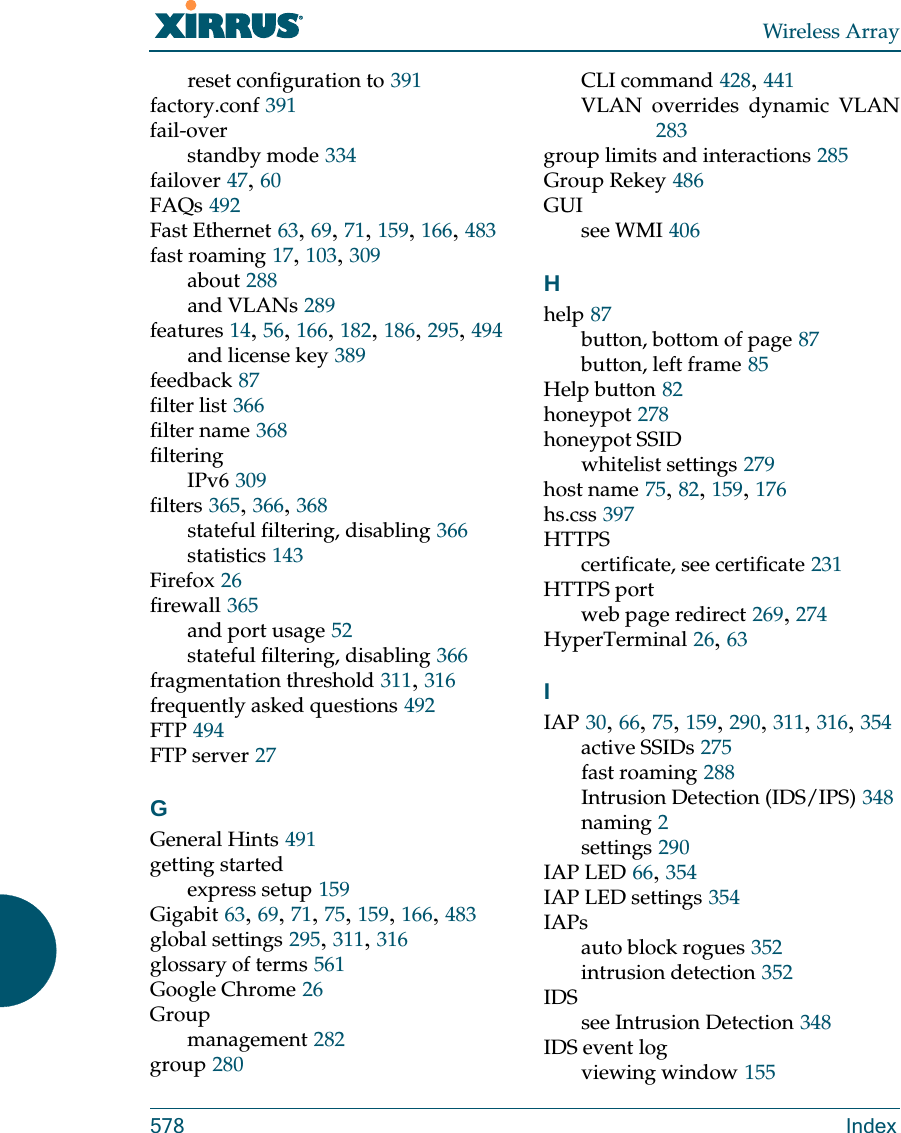
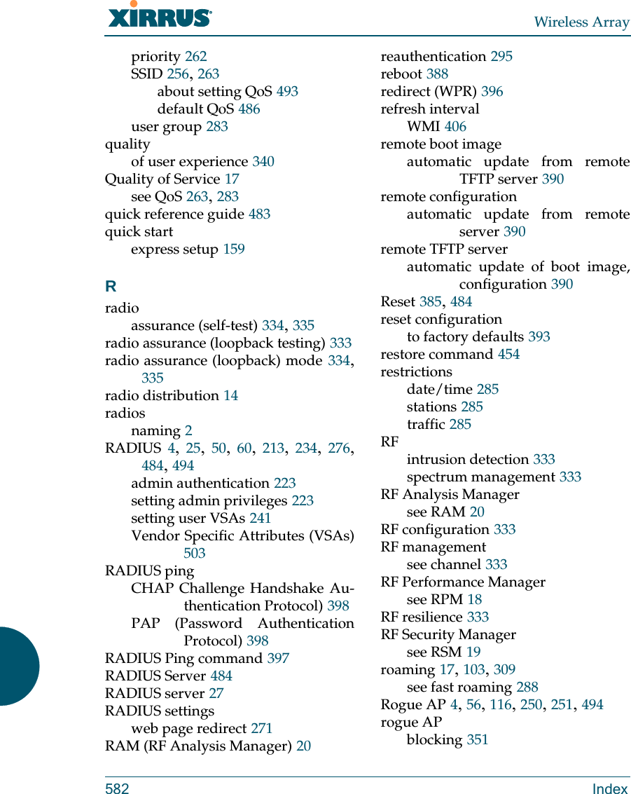
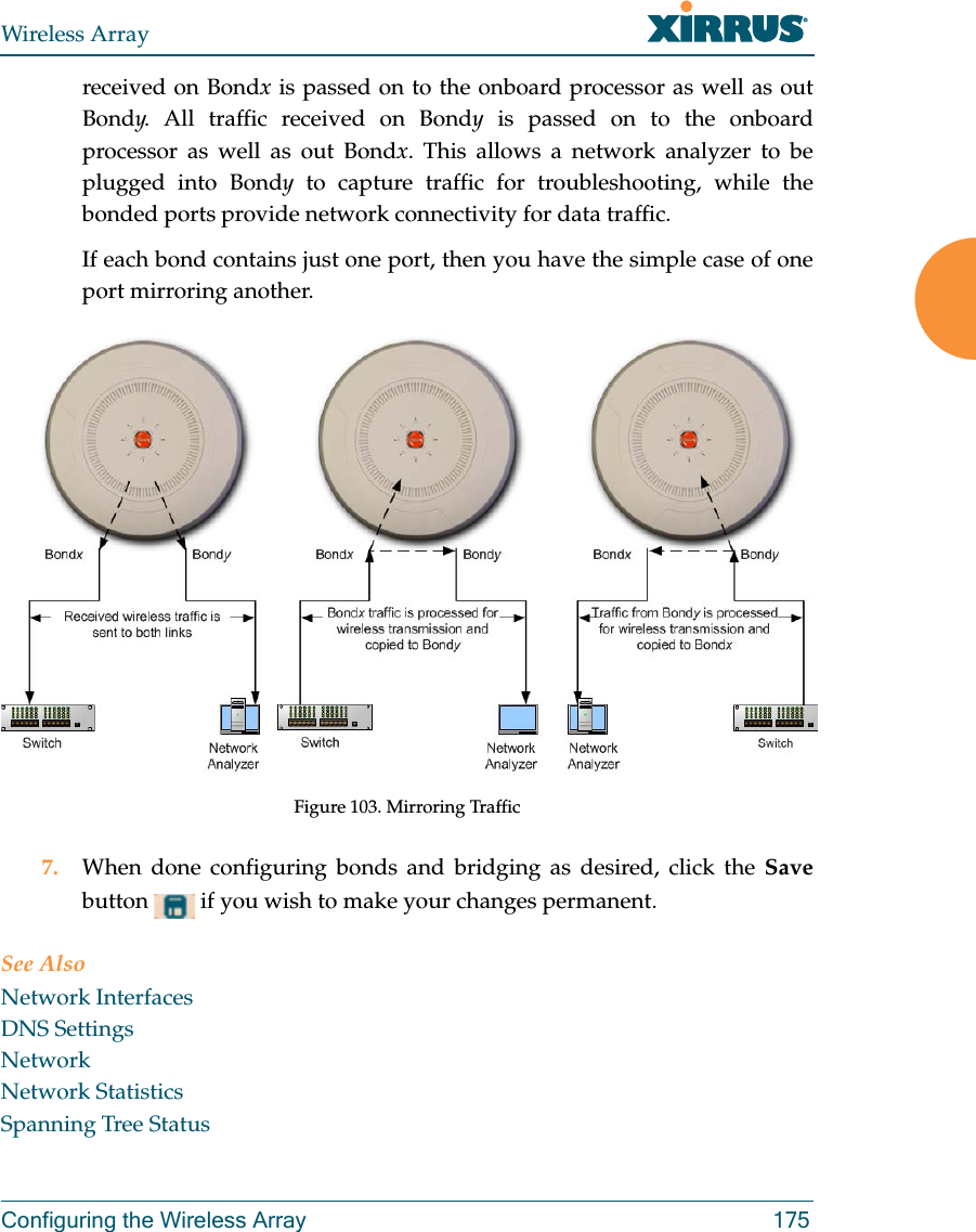
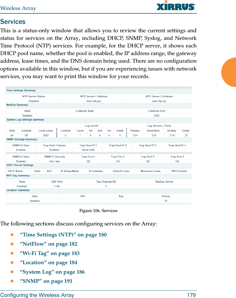
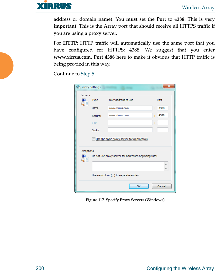
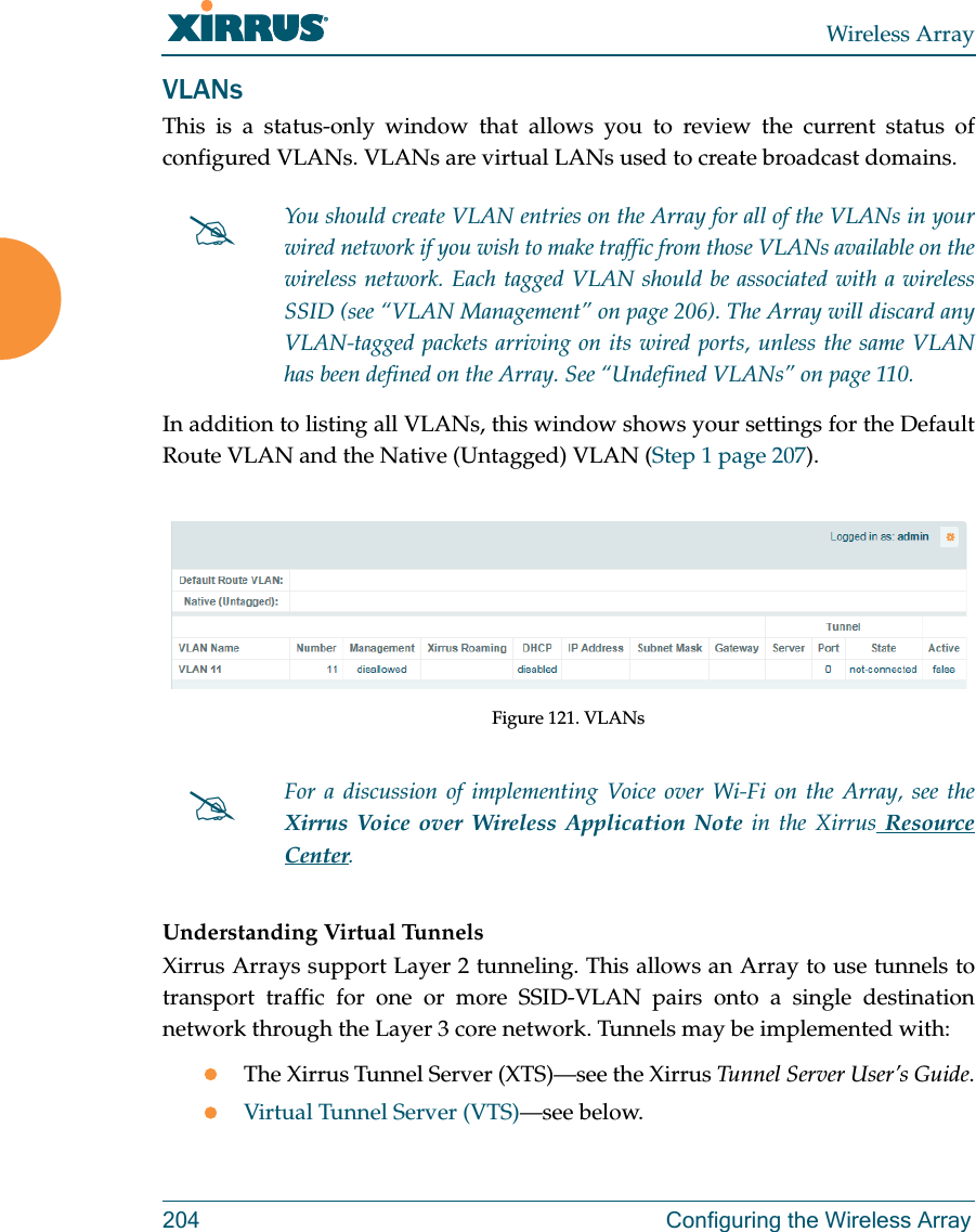
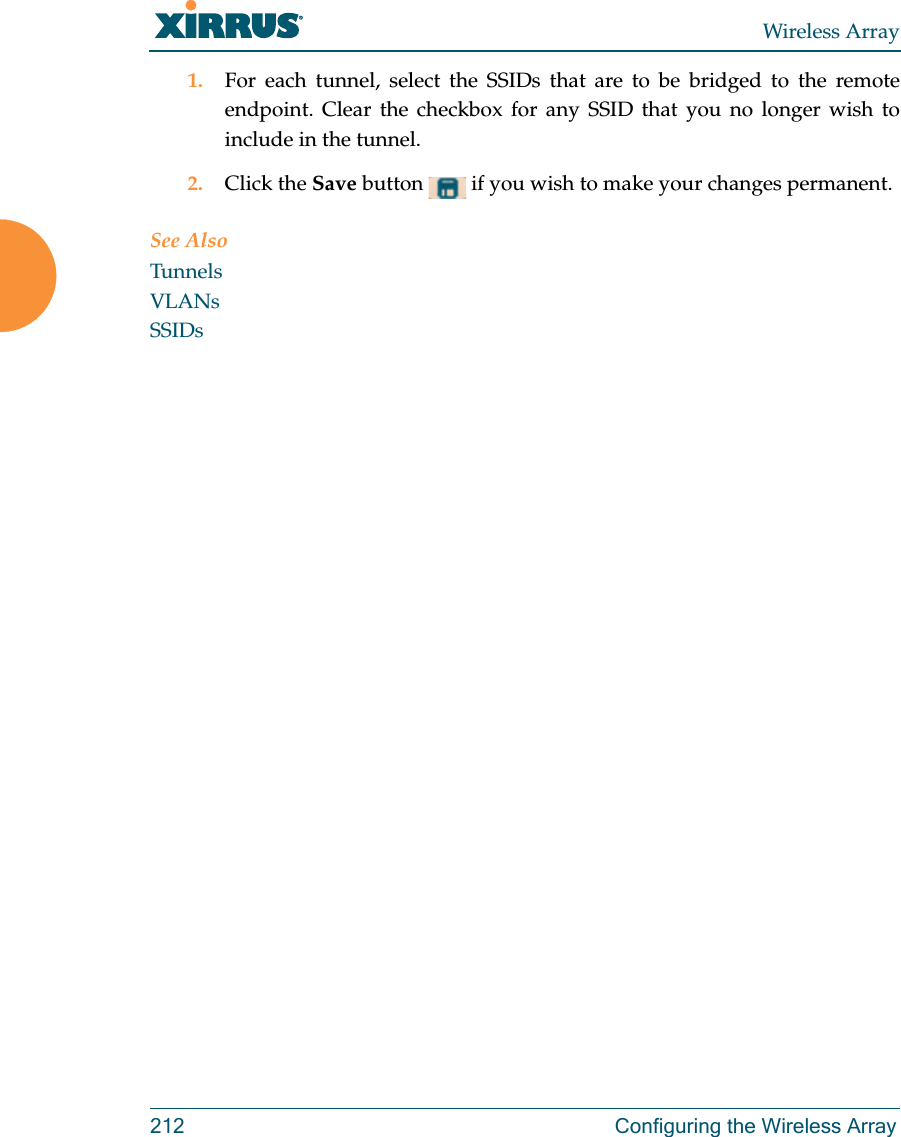
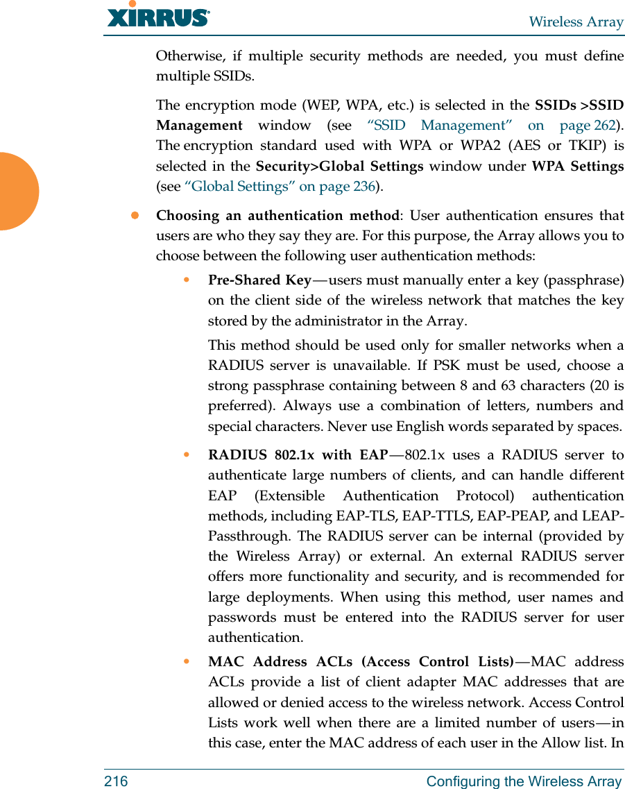
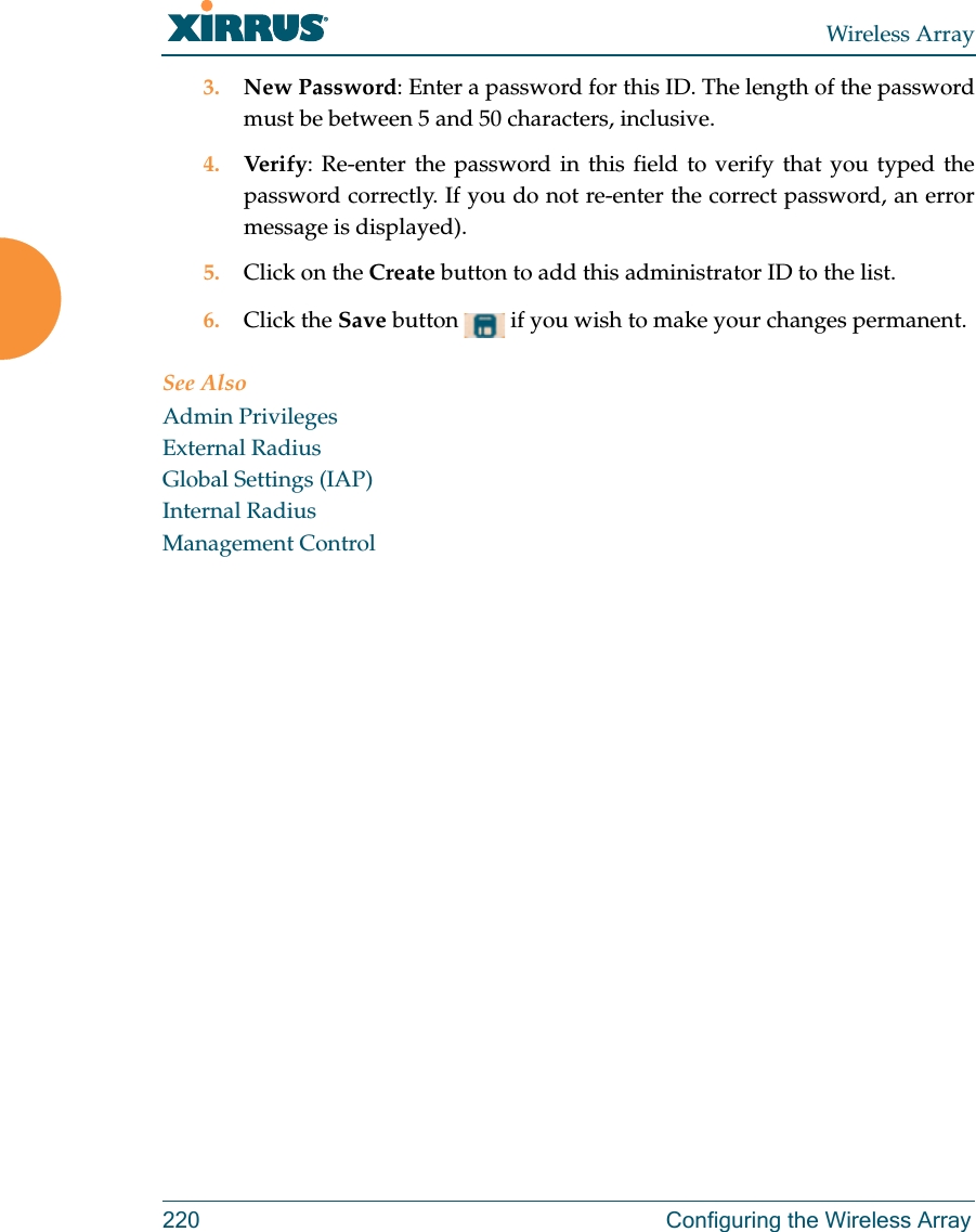
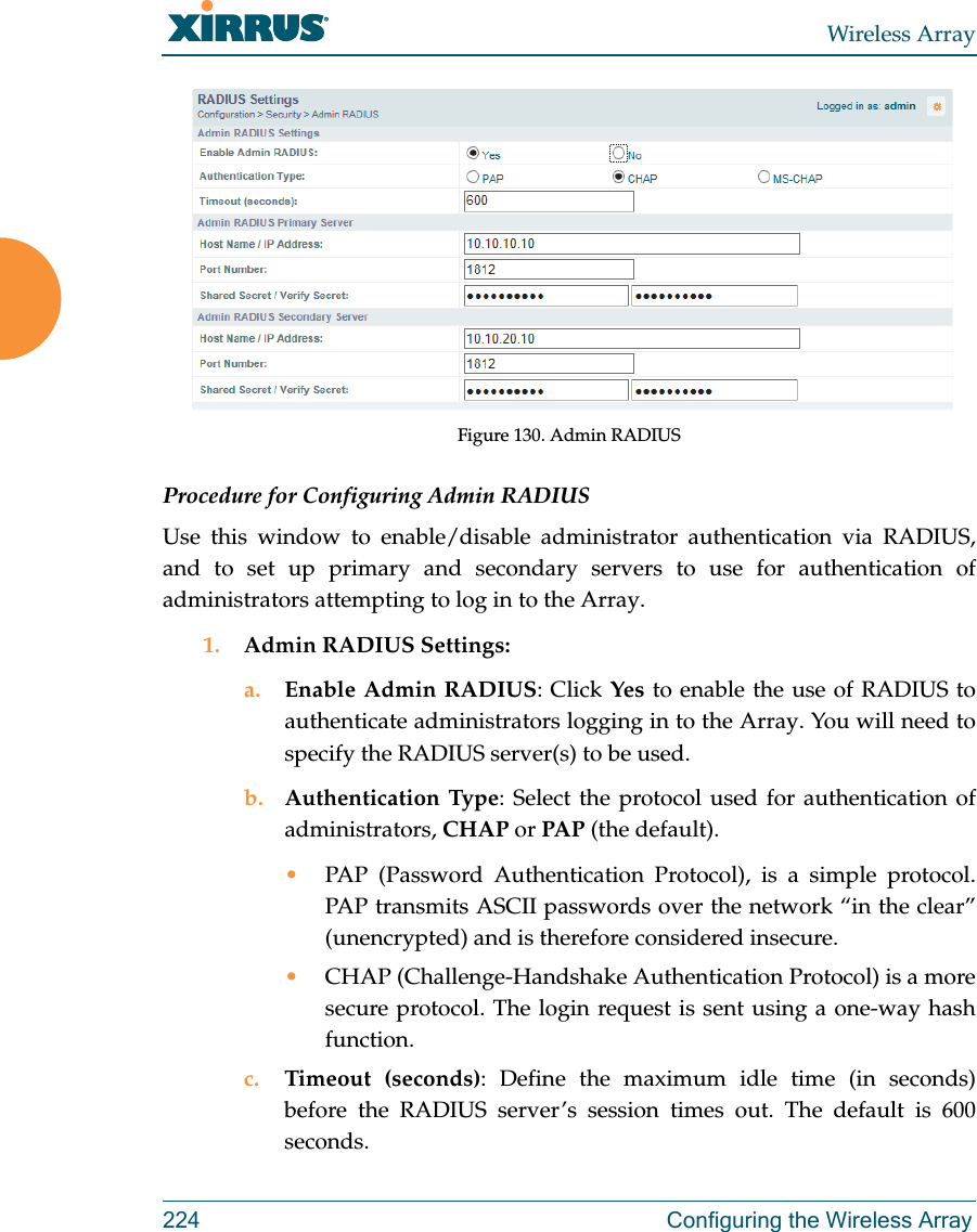
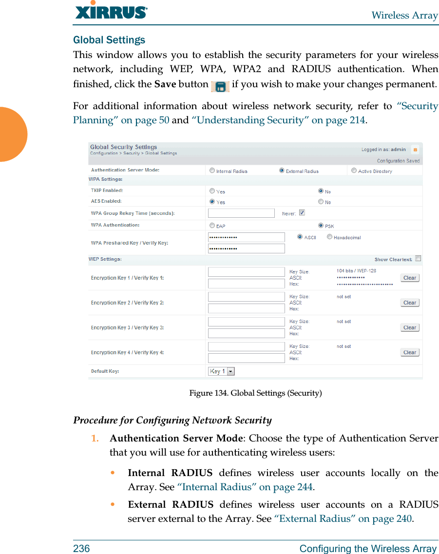
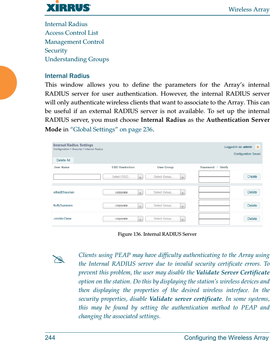
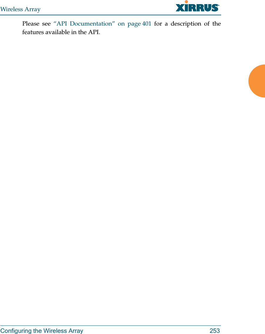
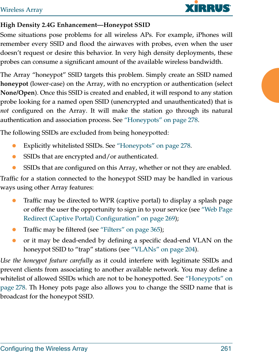
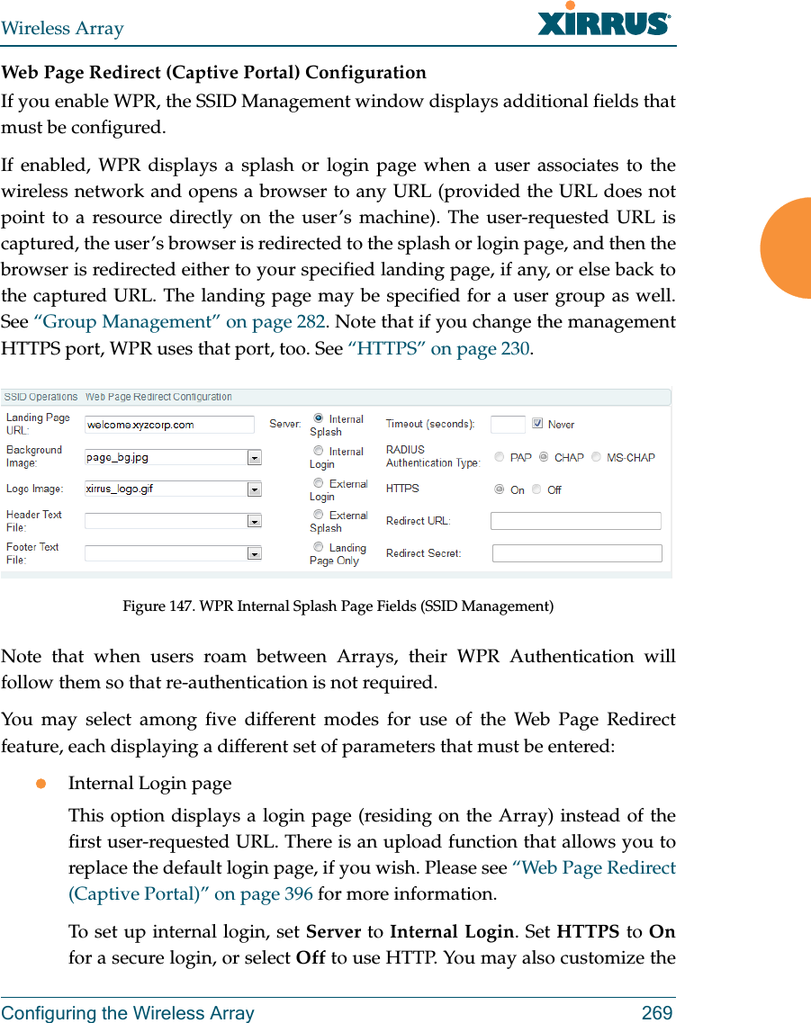
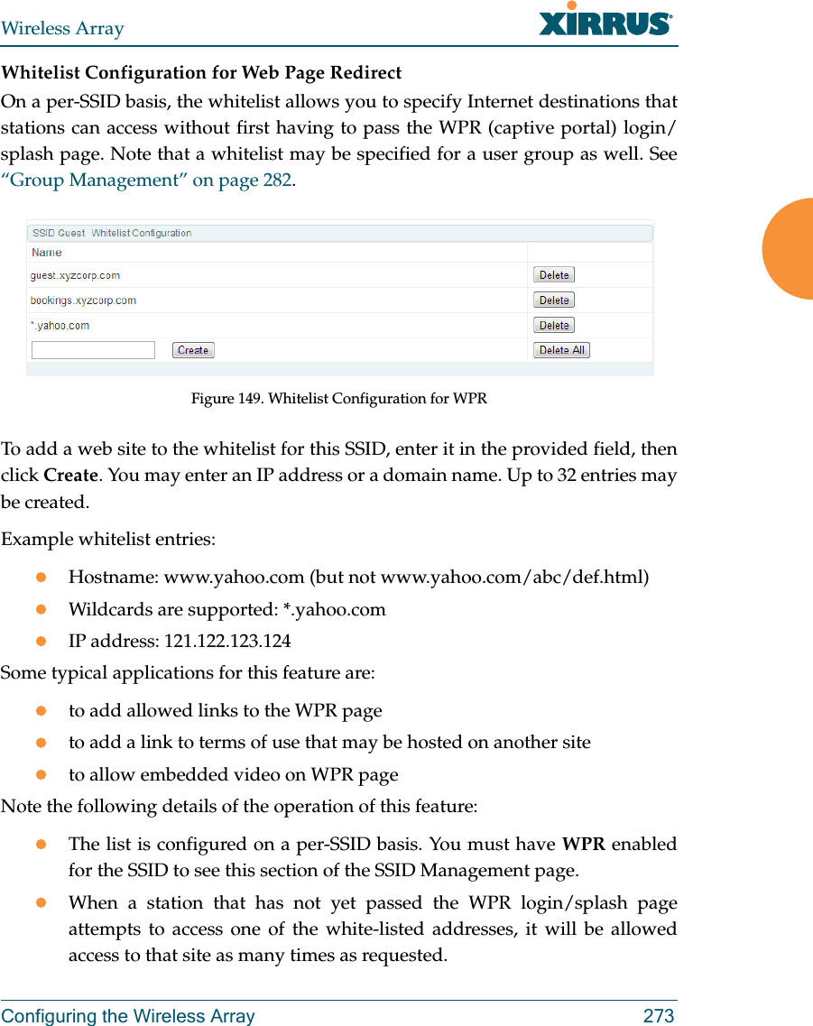
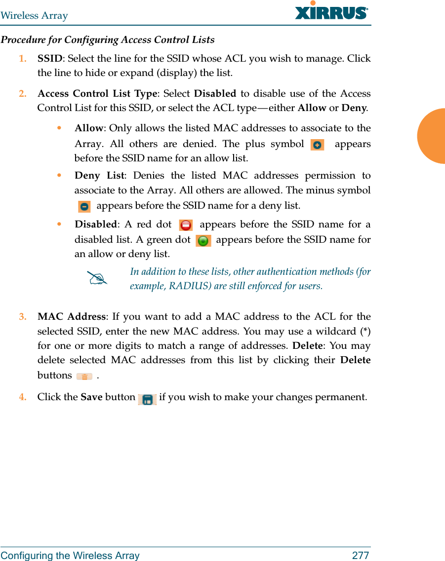
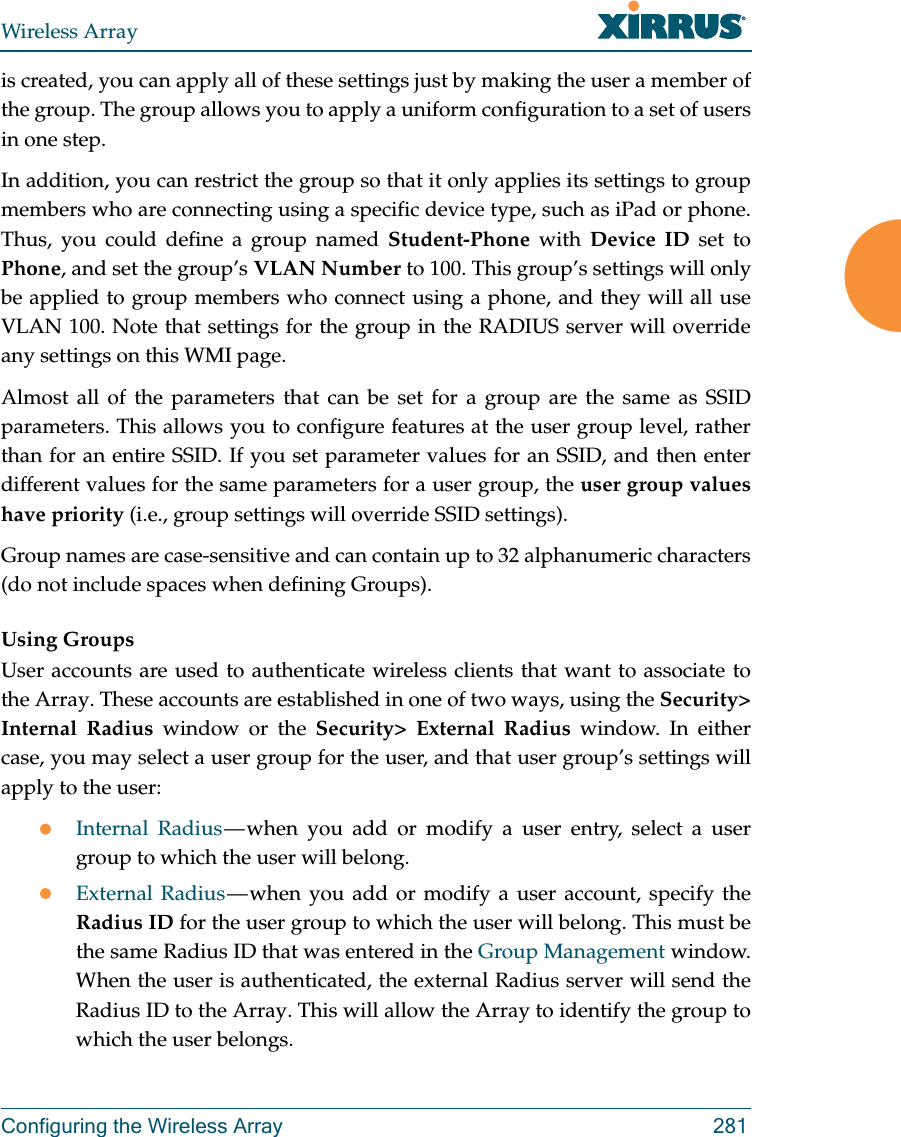
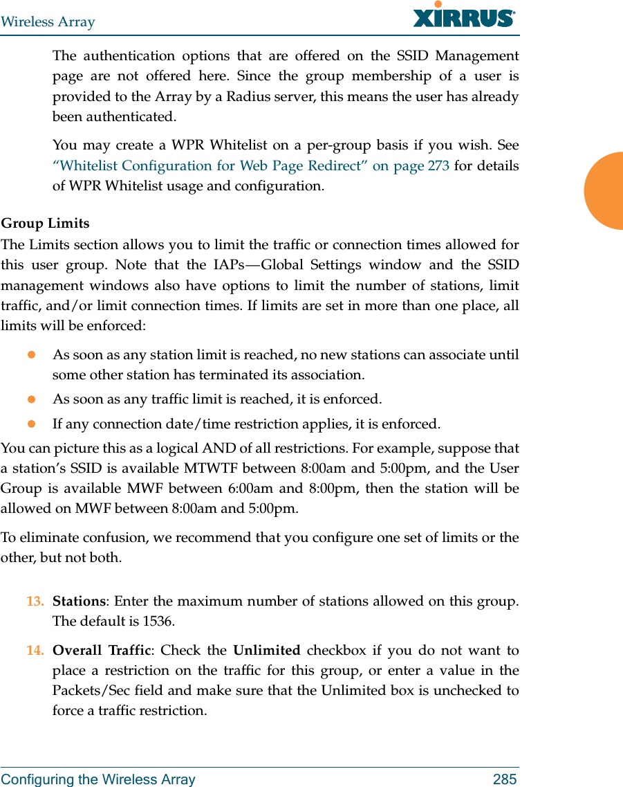
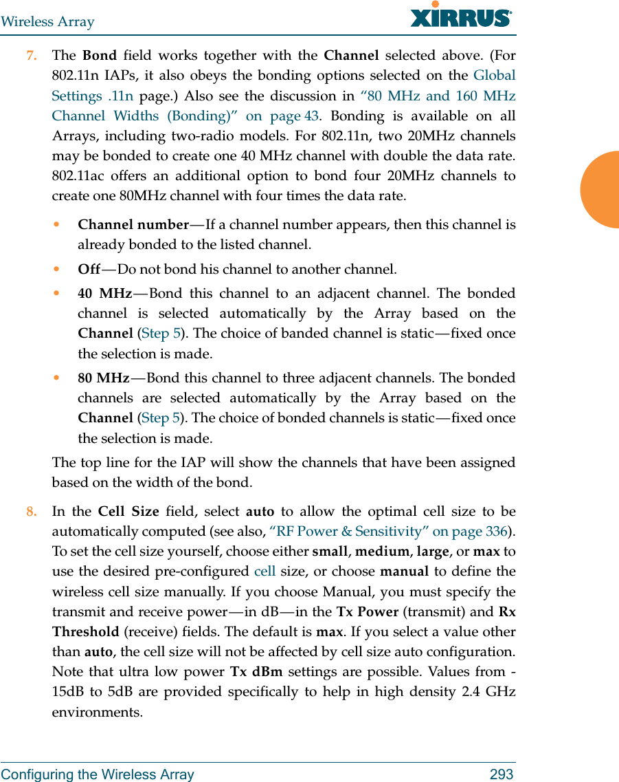
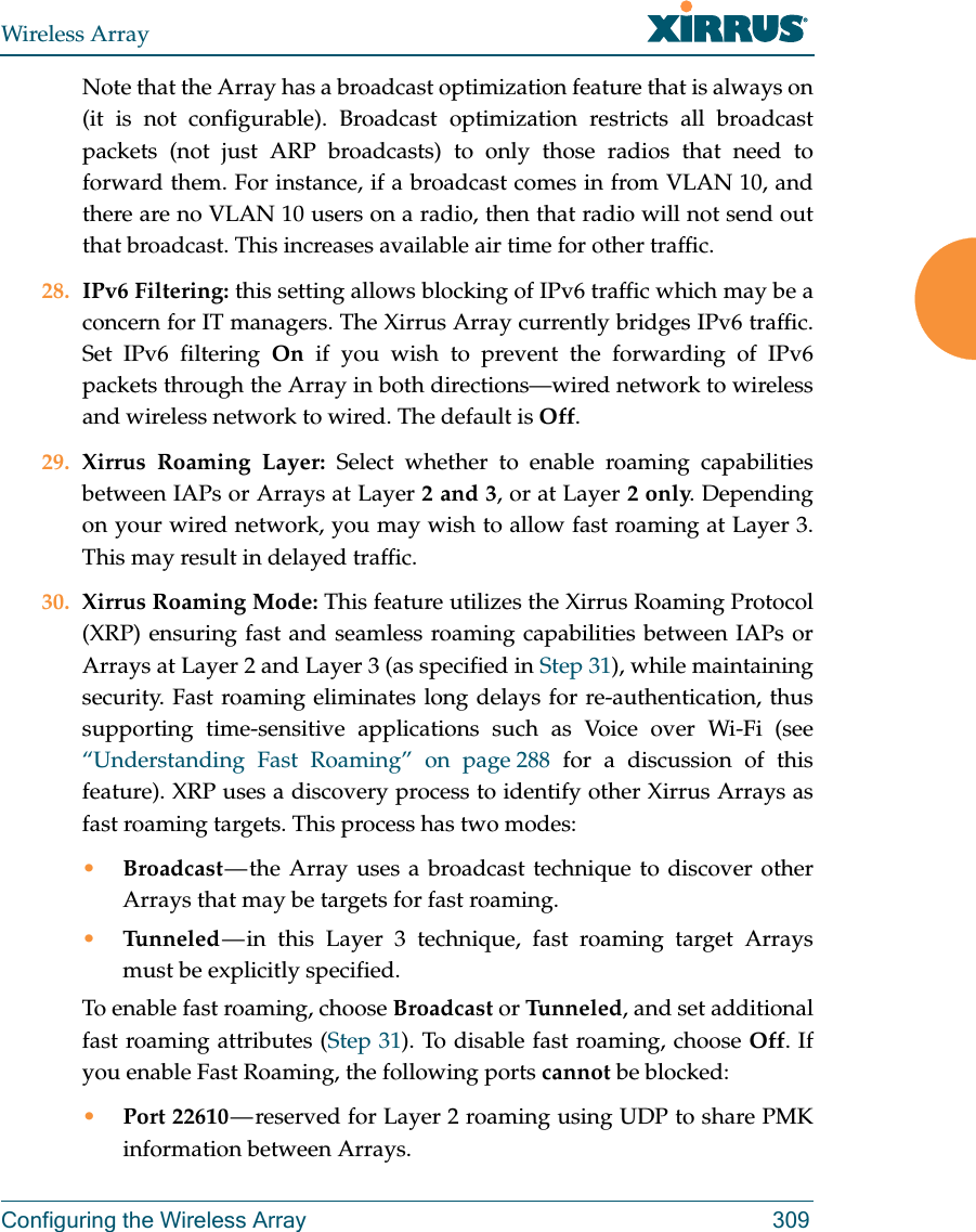
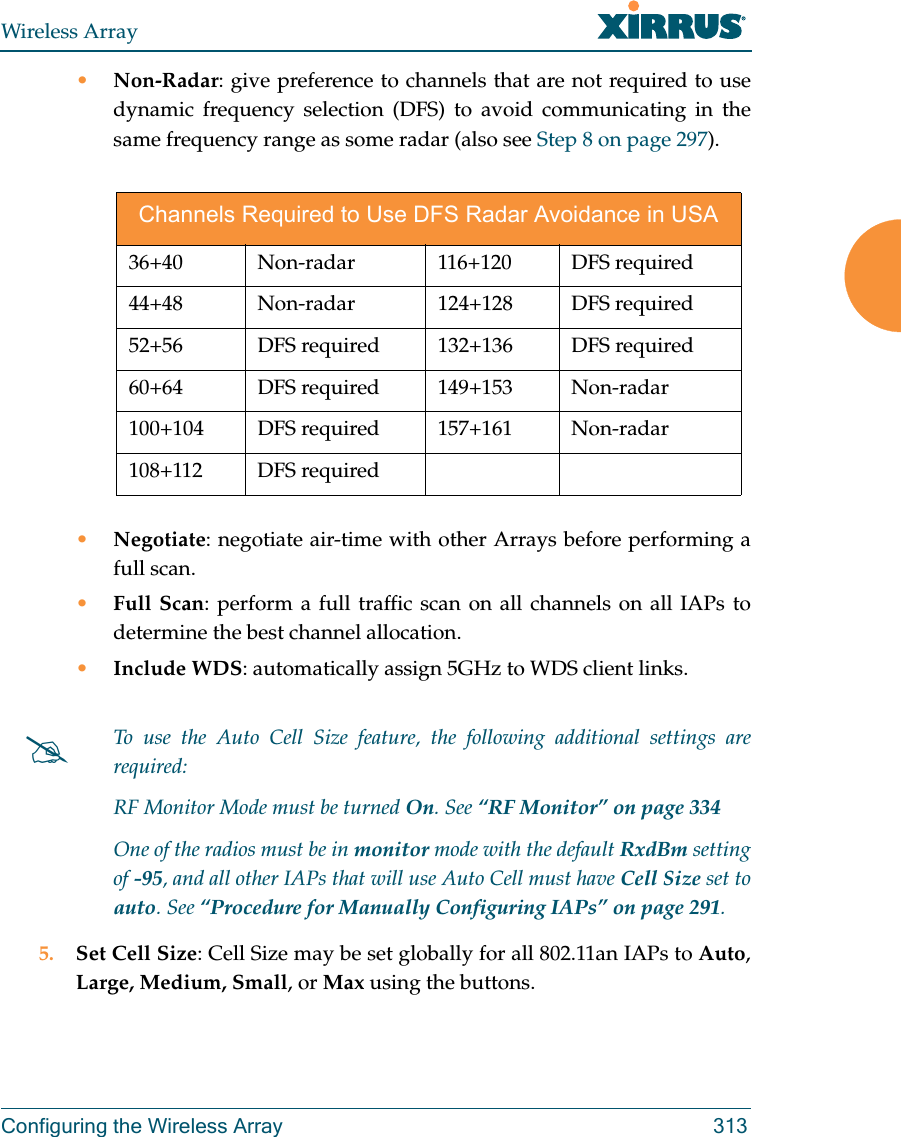
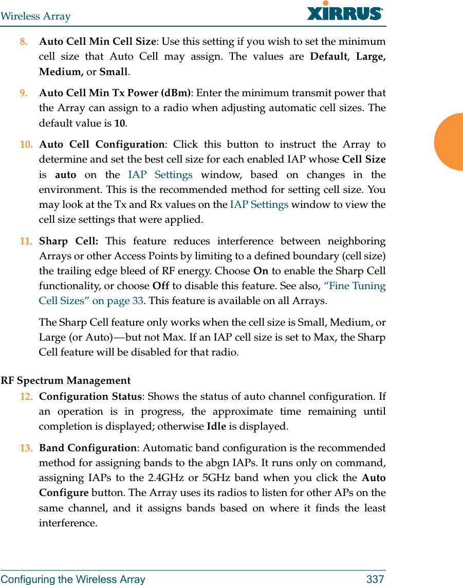
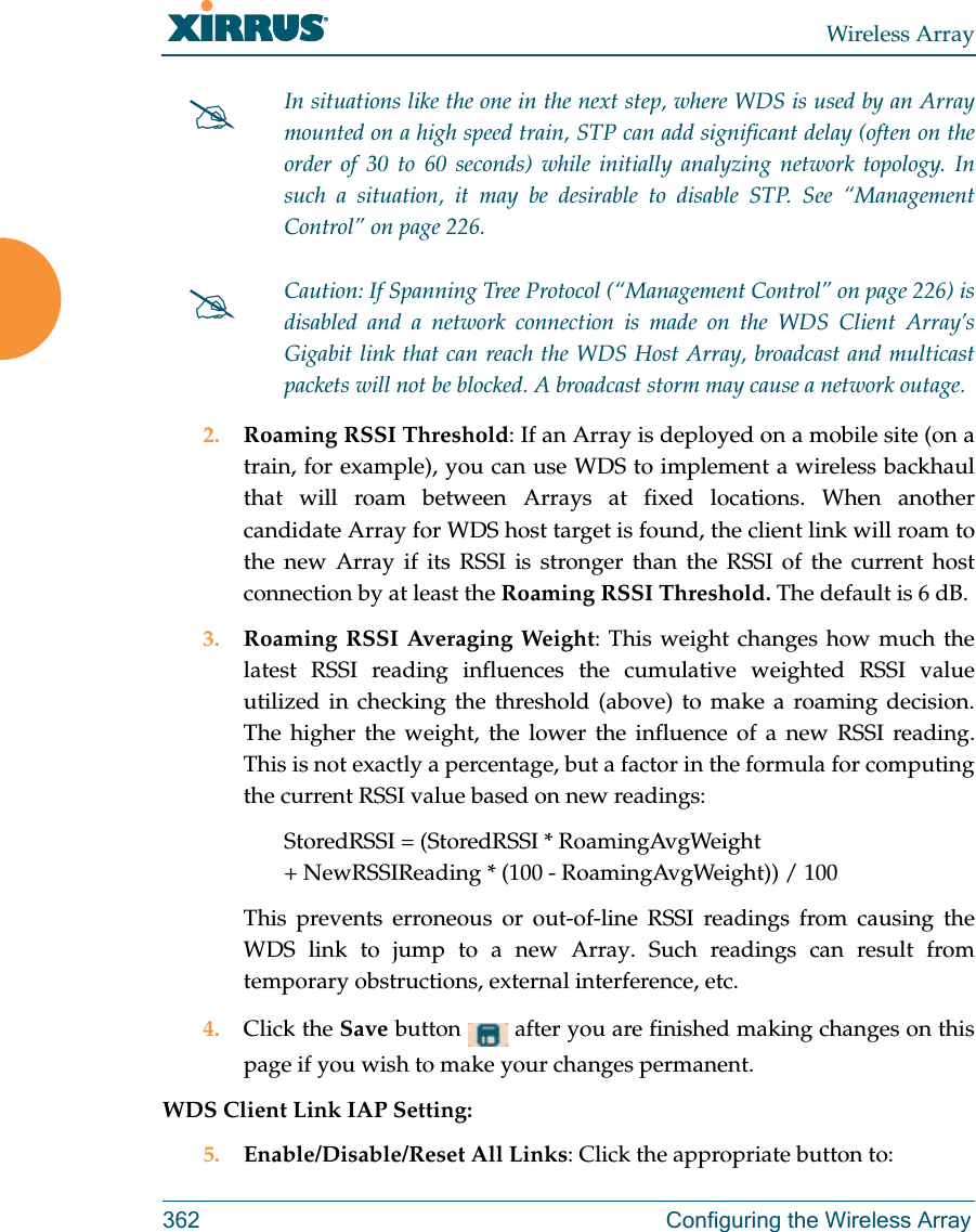
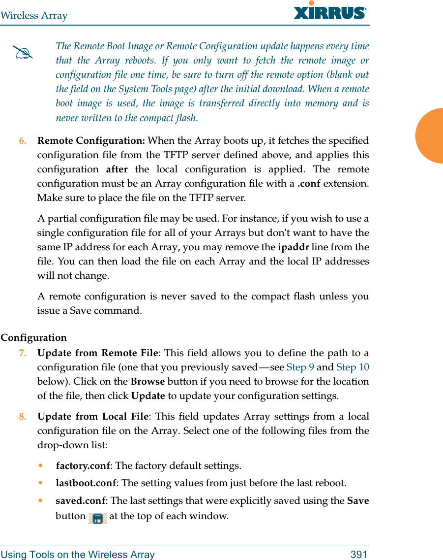
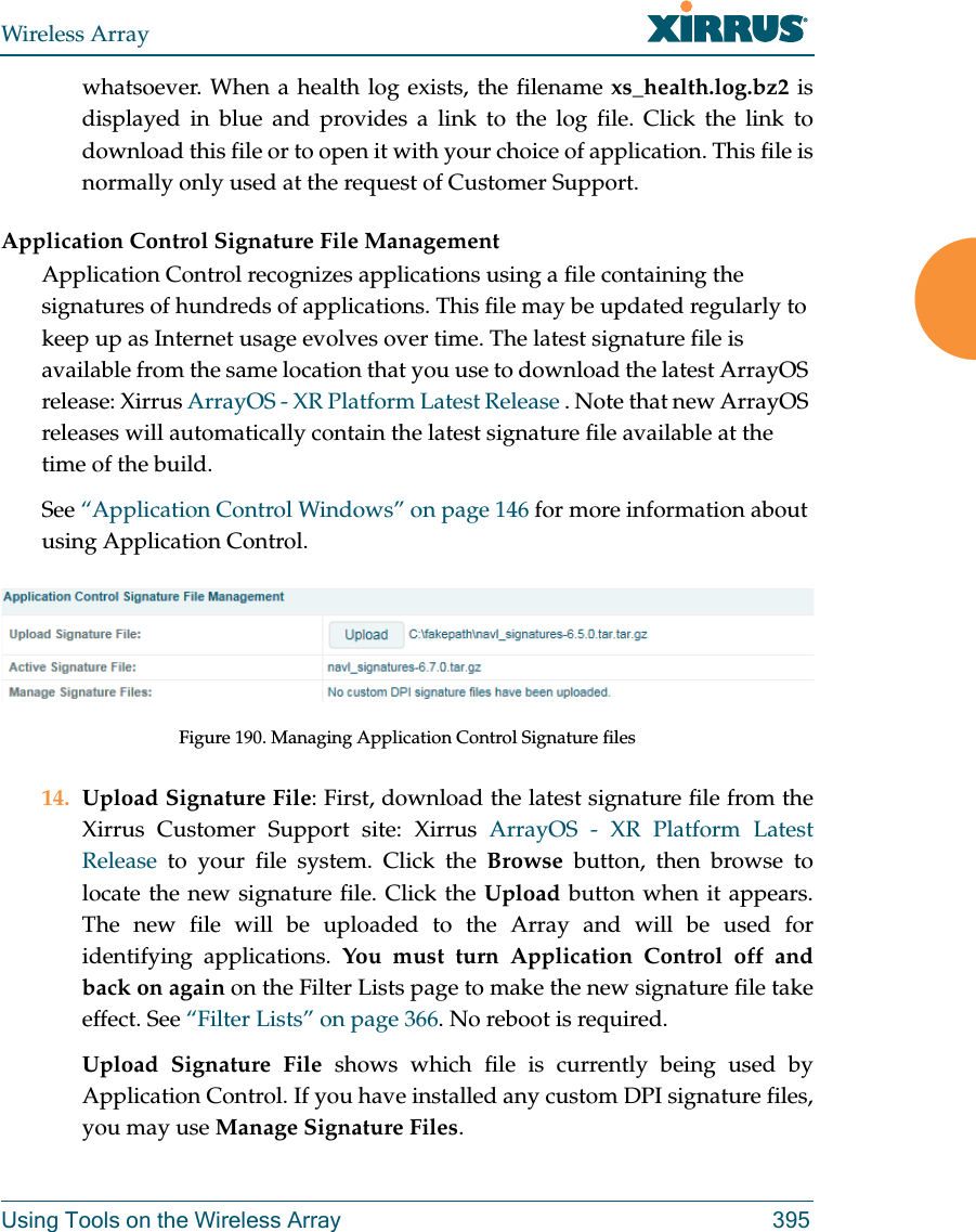
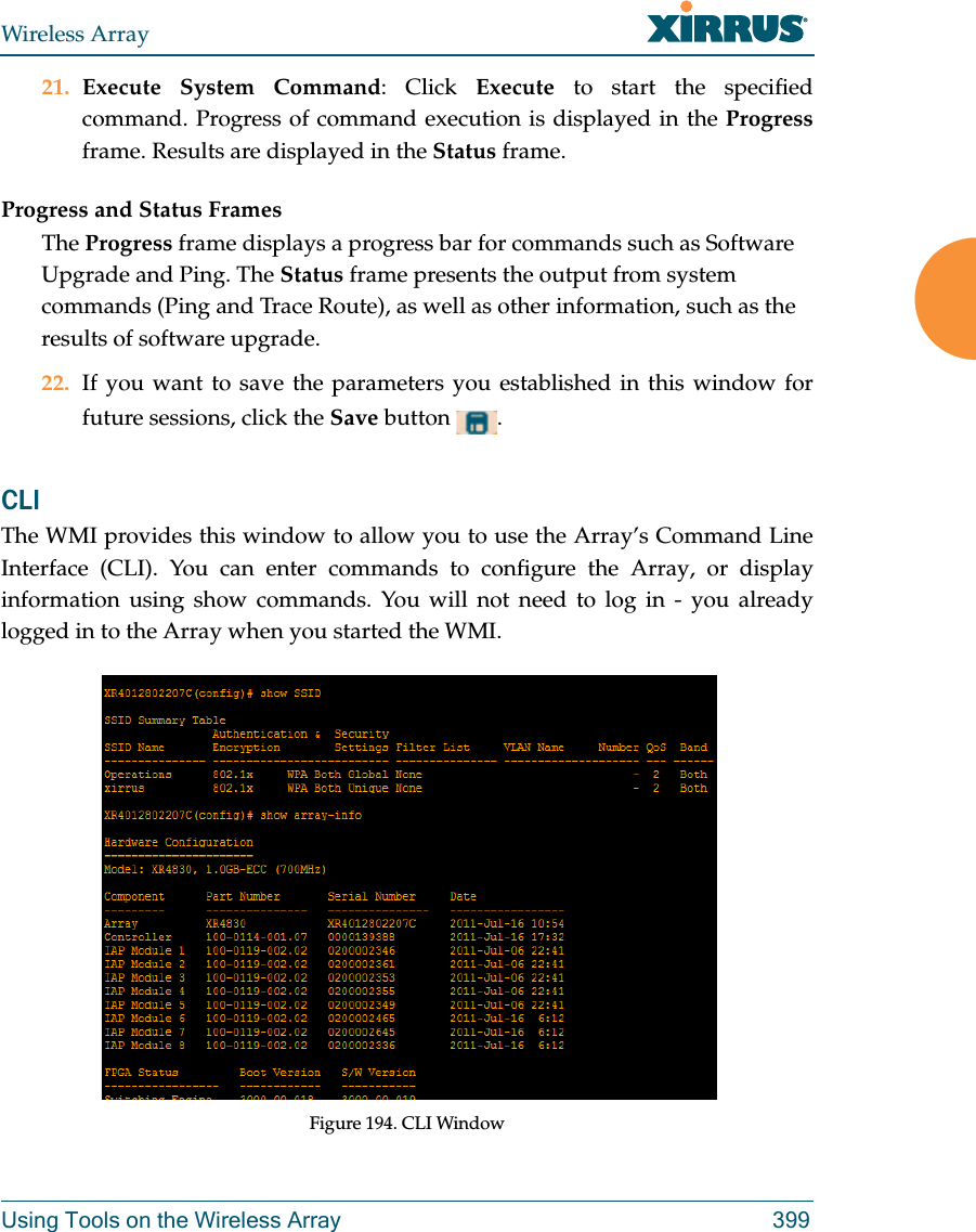
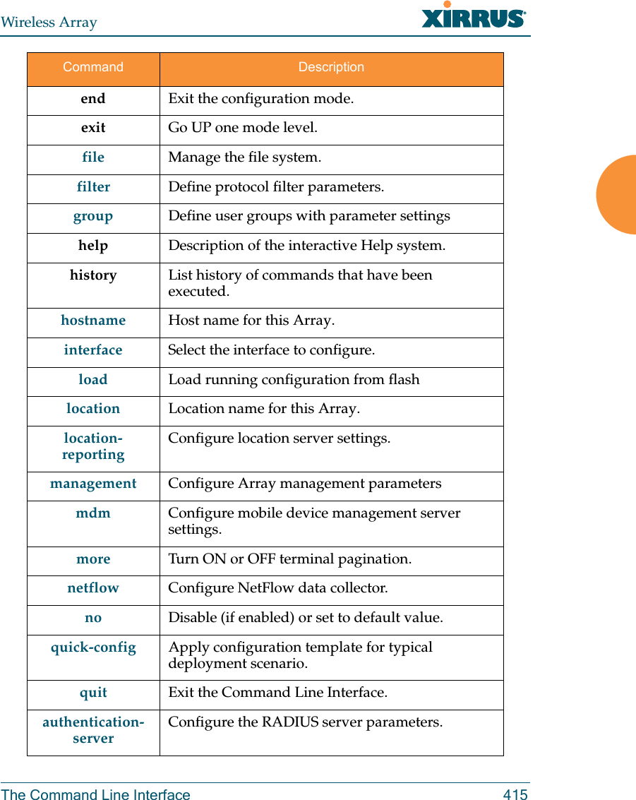
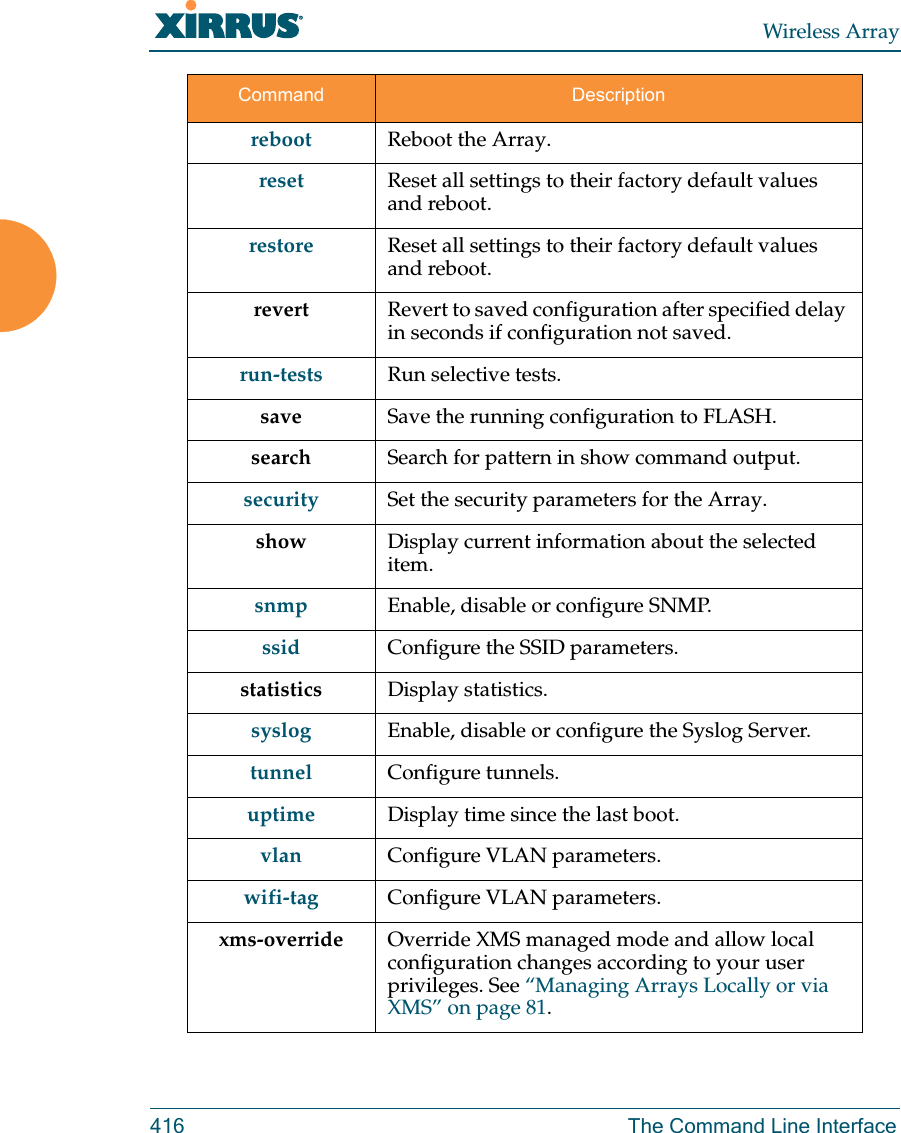
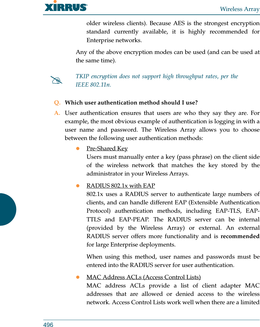
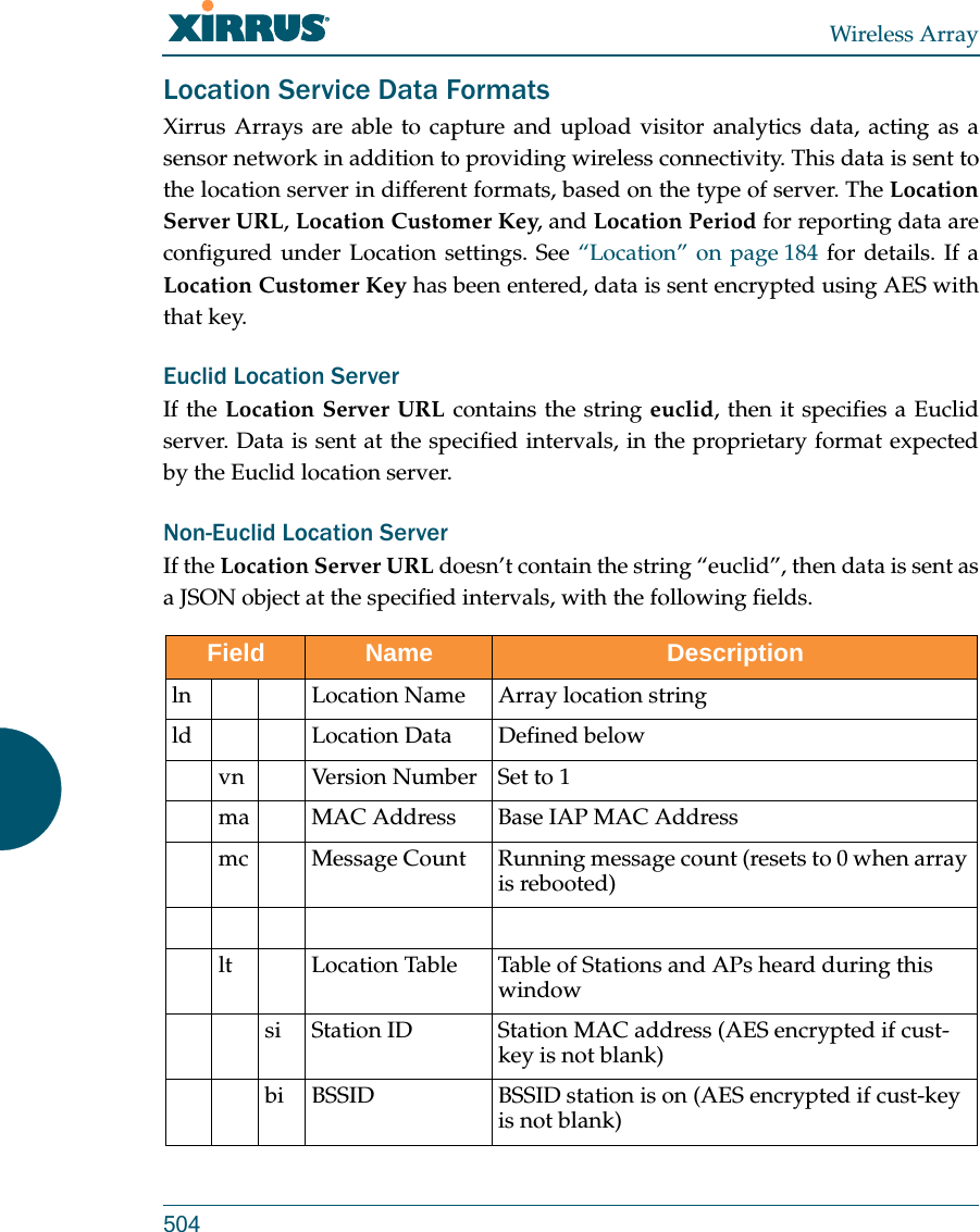
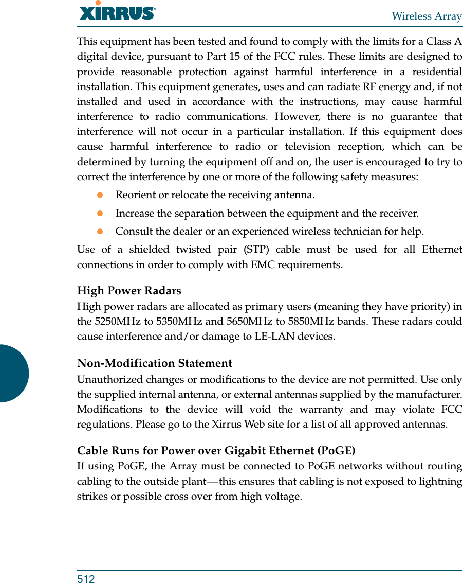
![Wireless ArrayThe Command Line Interface 413Top Level CommandsThis section offers an at-a-glance view of all top level commands — organized alphabetically. Top level commands are defined here as commands that are directly accessible from the root command prompt that consists of the name of the Array followed by a “#” sign (e.g. MyAP#). When inputting commands, be aware that all commands are case-sensitive.All other commands are considered second level configuration commands — these are the commands you use to configure specific elements of the Array’s features and functionality. For a listing of these commands with examples of command formats and structure, go to “Configuration Commands” on page 422.Root Command PromptThe following table shows the top level commands that are available from the root command prompt [MyAP]. Command Description@ Type @n to execute command n (as shown by the history command).configure Enter the configuration mode. See “Configuration Commands” on page 422. exit Exit the CLI and terminate your session — if this command is used at any level other than the root command prompt you will simply exit the current level (step back) and return to the previous level.help Show a description of the interactive help system. See also, “Getting Help” on page 411. history List history of commands that have been executed.more Turn terminal pagination ON or OFF.quit Exit the Command Line Interface (from any level).search Search for pattern in show command output.](https://usermanual.wiki/Cambium-Networks/XI-AC1300.Part-2/User-Guide-2284763-Page-257.png)
![Wireless Array414 The Command Line Interfaceconfigure CommandsThe following table shows the second level commands that are available with the top level configure command [MyAP(config)#].show Display information about the selected item. See “show Commands” on page 417. statistics Display statistical data about the Array. See “statistics Commands” on page 420. uptime Display the elapsed time since the last boot.xms-override Override XMS managed mode and allow local configuration changes according to your user privileges. See “Managing Arrays Locally or via XMS” on page 81.Command Description@ Type @n to execute command n (as shown by the history command).acl Configure the Access Control List.admin Define administrator access parameters.auth Configure Oauth tokens. cdp Configure Cisco Discovery Protocol settings. clear Remove/clear the requested elements.cluster Make configuration changes to multiple Arrays.contact-info Contact information for assistance on this Array.date-time Configure date and time settings.dhcp-server Configure the DHCP Server.dns Configure the DNS settings.Command Description](https://usermanual.wiki/Cambium-Networks/XI-AC1300.Part-2/User-Guide-2284763-Page-258.png)
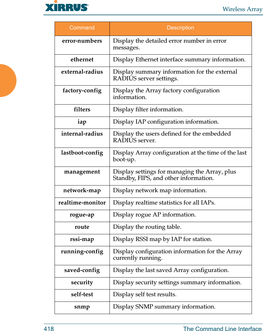
![Wireless ArrayThe Command Line Interface 417show CommandsThe following table shows the second level commands that are available with the top level show command [MyAP# show].Command Descriptionacl Display the Access Control List.admin Display the administrator list or login information.array-info Display system information.associated-stationsDisplay stations that have associated to the Array.boot-env Display Boot loader environment variables. capabilities Display detailed station capabilities. cdp Display Cisco Discovery Protocol settings.channel-list Display list of Array’s 802.11an and bgn channels. clear-text Display and enter passwords and secrets in the clear. conntrack Display the Connection Tracking table. console Display terminal settings.contact-info Display contact information.date-time Display date and time settings summary.dhcp-leases Display IP addresses (leases) assigned to stations by the DHCP server. dhcp-pool Display internal DHCP server settings summary information.diff Display the difference between configurations.dns Display DNS summary information.](https://usermanual.wiki/Cambium-Networks/XI-AC1300.Part-2/User-Guide-2284763-Page-261.png)
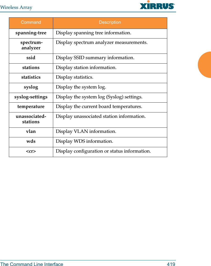
![Wireless Array420 The Command Line Interfacestatistics CommandsThe following table shows the second level commands that are available with the top level statistics command [MyAP# statistics].Command Descriptionethernet Display statistical data for all Ethernet interfaces.Ethernet Nameeth0, gig1, gig2Display statistical data for the defined Ethernet interface (either eth0, gig1 or gig2).FORMAT:statistics gig1 filter Display statistics for defined filters (if any).FORMAT:statistics filter [detail] filter-list Display statistics for defined filter list (if any).FORMAT:statistics filter <filter-list> iap Display statistical data for the defined IAP.FORMAT:statistics iap iap2station Display statistical data about associated stations.FORMAT:statistics station billwvlan Display statistical data for the defined VLAN. You must use the VLAN number (not its name) when defining a VLAN.FORMAT:statistics vlan 1](https://usermanual.wiki/Cambium-Networks/XI-AC1300.Part-2/User-Guide-2284763-Page-264.png)
![Wireless Array422 The Command Line InterfaceConfiguration CommandsAll configuration commands are accessed by using the configure command at the root command prompt (MyAP#). This section provides a brief description of each command and presents sample formats where deemed necessary. The commands are organized alphabetically. When inputting commands, be aware that all commands are case-sensitive.To see examples of some of the key configuration tasks and their associated commands, go to “Sample Configuration Tasks” on page 466.acl The acl command [MyAP(config)# acl] is used to configure the Access Control List.Command Descriptionadd Add a MAC address to the list.FORMAT:acl add AA:BB:CC:DD:EE:FFdel Delete a MAC address from the list.FORMAT:acl del AA:BB:CC:DD:EE:FFdisable Disable the Access Control ListFORMAT:acl disableenable Enable the Access Control ListFORMAT:acl enablereset Delete all MAC addresses from the list.FORMAT:acl reset](https://usermanual.wiki/Cambium-Networks/XI-AC1300.Part-2/User-Guide-2284763-Page-266.png)
![Wireless ArrayThe Command Line Interface 423admin The admin command [MyAP(config-admin)#] is used to configure the Administrator List.Command Descriptionadd Add a user to the Administrator List.FORMAT:admin add [userID]del Delete a user to the Administrator List.FORMAT:admin del [userID]edit Modify user in the Administrator List.FORMAT:admin edit [userID]radius Define a RADIUS server to be used for authenticating administrators.FORMAT:admin radius [disable | enable | off | on | timeout <seconds> | auth-type [PAP | CHAP]] admin radius [primary |secondary] port <portid> server [<ip-addr> | <host>] secret <shared-secret>reset Delete all users and restore the default user.FORMAT:admin reset](https://usermanual.wiki/Cambium-Networks/XI-AC1300.Part-2/User-Guide-2284763-Page-267.png)
![Wireless Array424 The Command Line InterfaceauthThe auth command [MyAP(config)# auth] is used to configure Oauth tokens. See also, “OAuth 2.0 Management” on page 251. cdp The cdp command [MyAP(config)# cdp] is used to configure the Cisco Discovery Protocol.Command Descriptionadd Add an Oauth token.FORMAT:auth add <token> client <client> grant <grant> expiration <expiration> code <code> type <type> [agent <agent>] [scope <scope>]del Delete an Oauth token.FORMAT:auth del <Oauth token>reset Delete all Oauth tokens.FORMAT:auth resetCommand Descriptiondisable Disable the Cisco Discovery ProtocolFORMAT:cdp disableenable Enable the Cisco Discovery ProtocolFORMAT:cdp enable](https://usermanual.wiki/Cambium-Networks/XI-AC1300.Part-2/User-Guide-2284763-Page-268.png)
![Wireless ArrayThe Command Line Interface 425hold-time Select CDP message hold time before messages received from neighbors expire.FORMAT:cdp hold-time [# seconds]interval The Array sends out CDP announcements at this interval. FORMAT:cdp interval [# seconds] off Disable the Cisco Discovery ProtocolFORMAT:cdp offon Enable the Cisco Discovery ProtocolFORMAT:cdp onCommand Description](https://usermanual.wiki/Cambium-Networks/XI-AC1300.Part-2/User-Guide-2284763-Page-269.png)
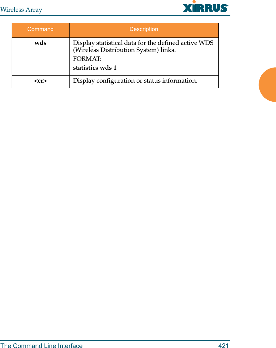
![Wireless Array426 The Command Line Interfaceclear The clear command [MyAP(config)# clear] is used to clear requested elements.Command Descriptionarp Clear the arp table entry for a requested IP address, or clear all entries if no IP address is entered.FORMAT:clear arp [ipaddress]authentication Deauthenticate a station (specified by MAC address, hostname, or IP address). If you specify the permanent option, then the station is deauthenticated and put on the access control list.FORMAT:clear authentication [permanent] [authenticated station]history Clear the history of CLI commands executed.FORMAT:clear history screen Clear the screen where you’re viewing CLI output.FORMAT:clear screenstation-assuranceClear all station assurance data, but continue to collect new data.FORMAT:clear station-assurancestatistics Clear the statistics for thee change, but it won’t show up requested element.FORMAT:clear statistics [ethname | all-eth | applications | filters |iap | station | vlan | wds]](https://usermanual.wiki/Cambium-Networks/XI-AC1300.Part-2/User-Guide-2284763-Page-270.png)
![Wireless Array428 The Command Line InterfaceclusterThe cluster command [Xirrus_Wi-Fi_Array(config)# cluster] is used to create and operate clusters. Clusters allow you to configure multiple Arrays at the same time. Using CLI (or WMI), you may define a set of Arrays that are members of the cluster. Then you may switch the Array to Cluster operating mode for a selected cluster, which sends all successive configuration commands issued via CLI or WMI to all of the member Arrays. When you exit cluster mode, configuration commands revert to applying only to the Array to which you are connected.For more information, see “Clusters” on page 374. Command Descriptionadd Create a new Array cluster. Enters edit mode for that cluster to allow you to specify the Arrays that belong to the cluster.FORMAT:cluster add [cluster-name]del Delete an Array cluster. Type del ? to list the existing clusters.FORMAT:cluster del [cluster-name]edit Enter edit mode for selected cluster to add or delete Arrays that belong to the cluster.FORMAT:cluster edit [cluster-name]end Exit Cluster configuration mode. Configuration returns to normal operation, affecting this Array only.FORMAT:cluster end](https://usermanual.wiki/Cambium-Networks/XI-AC1300.Part-2/User-Guide-2284763-Page-272.png)
![Wireless ArrayThe Command Line Interface 429contact-info The contact-info command [MyAP(config)# contact-info] is used for managing administrator contact information.operate Enter Cluster operation mode. All configuration commands are applied to all of the selected cluster’s member Arrays until you give the end command (see above). FORMAT:cluster operate [cluster-name]reset Delete all clusters.FORMAT:cluster resetCommand Descriptionemail Add an email address for the contact (must be in quotation marks).FORMAT:contact-info email [“contact@mail.com”]name Add a contact name (must be in quotation marks).FORMAT:contact-info name [“Contact Name”]phone Add a telephone number for the contact (must be in quotation marks).FORMAT:contact-info phone [“8185550101”]Command Description](https://usermanual.wiki/Cambium-Networks/XI-AC1300.Part-2/User-Guide-2284763-Page-273.png)
![Wireless Array430 The Command Line Interfacedate-time The date-time command [MyAP(config-date-time)#] is used to configure the date and time parameters. Your Array supports the Network Time Protocol (NTP) in order to ensure that the Array’s internal time is accurate. NTP is set to UTC time by default; however, you can set the time zone so that your Array will display local time. This is done by defining an offset from the UTC value. For example, Pacific Standard Time is 8 hours behind UTC time, so the offset from UTC time would be -8.Command Descriptiondst_adjust Enable adjustment for daylight savings.FORMAT:date-time dst_adjustno Disable daylight savings adjustment.FORMAT:date-time no dst_adjustntp Enable the NTP server.FORMAT:date-time ntp on (or off to disable)offset Set an offset from Greenwich Mean Time.FORMAT:date-time no dst_adjustset Set the date and time for the Array.FORMAT:date-time set [10:24 10/23/2007]timezone Configure the time zone.FORMAT:date-time timezone [-8]](https://usermanual.wiki/Cambium-Networks/XI-AC1300.Part-2/User-Guide-2284763-Page-274.png)
![Wireless ArrayThe Command Line Interface 431dhcp-server The dhcp-server command [MyAP(config-dhcp-server)#] is used to add, delete and modify DHCP pools.Command Descriptionadd Add a DHCP pool.FORMAT:dhcp-server add [dhcp pool]del Delete a DHCP pool.FORMAT:dhcp-server del [dhcp pool]edit Edit a DHCP poolFORMAT:dhcp-server edit [dhcp pool]reset Delete all DHCP pools.FORMAT:dhcp-server reset](https://usermanual.wiki/Cambium-Networks/XI-AC1300.Part-2/User-Guide-2284763-Page-275.png)
![Wireless Array432 The Command Line Interfacedns The dns command [MyAP(config-dns)#] is used to configure your DNS parameters.Command Descriptiondomain Enter your domain name.FORMAT:dns domain [www.mydomain.com]server1 Enter the IP address of the primary DNS server.FORMAT:dns server1 [1.2.3.4]server2 Enter the IP address of the secondary DNS server.FORMAT:dns server1 [2.3.4.5]server3 Enter the IP address of the tertiary DNS server.FORMAT:dns server1 [3.4.5.6]](https://usermanual.wiki/Cambium-Networks/XI-AC1300.Part-2/User-Guide-2284763-Page-276.png)
![Wireless ArrayThe Command Line Interface 433file The file command [MyAP(config-file)#] is used to manage files.Command Descriptionactive-image Validate and commit a new array software image. backup-image Validate and commit a new backup software image. check-image Validate a new array software image. chkdsk Check flash file system.copycpCopy a file to another file.FORMAT:file copy [sourcefile destinationfile]dir List the contents of a directory.FORMAT:file dir [directory]erase Delete a file from the FLASH file system.FORMAT:file erase [filename]format Format flash file system.ftp Open an FTP connection with a remote server. Files will be transferred in binary mode. FORMAT:file ftp host {<hostname> |<ip>} [port <port_#>] [user {anonymous | <username> password <passwd> } ] { put <source_file> [<dest_file>] | get <source_file> [<dest_file>] }Note: Any time you transfer any kind of software image file for the Array, it must be transferred in binary mode, or the file may be corrupted.](https://usermanual.wiki/Cambium-Networks/XI-AC1300.Part-2/User-Guide-2284763-Page-277.png)
![Wireless Array434 The Command Line Interfacehttp-get Perform an HTTP file download. This is the preferred method of downloading files for XMS Cloud. FORMAT:http-get [no-cert-check] <url> [<local_file>]no-cert-check causes the array to download the file even if the SSL certificate is invalid, expired, or not signed by a recognized CA<url> is a standard HTTP URL, e.g. https://file.example.com:8080/mydir/myfile.ext.http:// or https:// may be omitted, in which case HTTP is assumed<local_file> is an optional parameter that describes the path and name where the file should be savedif no local_file is specified, the file will be saved in the root of the flash storagethe local_file does support specifying a directory, which will be created if it doesn't already existlist List the contents of a file.FORMAT:file list [filename]Command Description](https://usermanual.wiki/Cambium-Networks/XI-AC1300.Part-2/User-Guide-2284763-Page-278.png)
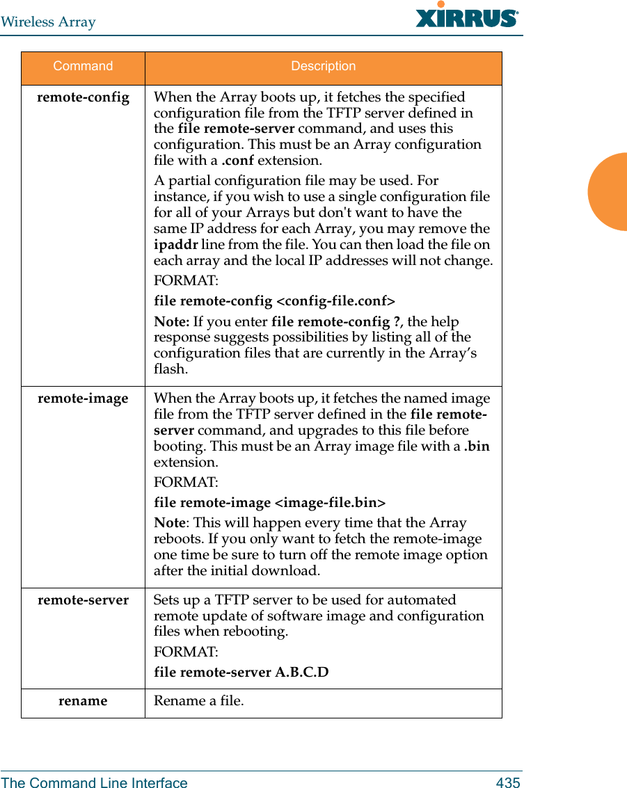
![Wireless Array436 The Command Line Interfacescp Copy a file to or from a remote system. You may specify the port to use.tftp Open a TFTP connection with a remote server.FORMAT:file tftp host {<hostname> |<ip>} [port <port_#>] [user {anonymous | <username> password <passwd> } ] { put <source_file> [<dest_file>] | get <source_file> [<dest_file>] }Note: Any time you transfer any kind of software image file for the Array, it must be transferred in binary mode, or the file may be corrupted. Command Description](https://usermanual.wiki/Cambium-Networks/XI-AC1300.Part-2/User-Guide-2284763-Page-280.png)
![Wireless ArrayThe Command Line Interface 437filter The filter command [MyAP(config-filter)#] is used to manage protocol filters and filter lists.Command Descriptionadd Add a filter. Details about the air cleaner feature are after the end of this table.FORMAT:filter add [air-cleaner |name]add-list Add a filter list.FORMAT:filter add-list [name]del Delete a filter.FORMAT:filter del [name]del-list Delete a filter list.FORMAT:filter del-list [name]edit Edit a filter.FORMAT:filter edit [name type]edit-list Edit a filter listFORMAT:filter edit-list [name type]enable Enable a filter list.FORMAT:filter enable move Change a filter priority.FORMAT:filter move [name priority]](https://usermanual.wiki/Cambium-Networks/XI-AC1300.Part-2/User-Guide-2284763-Page-281.png)
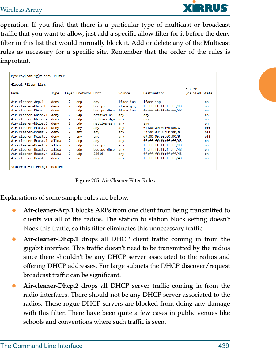
![Wireless Array438 The Command Line InterfaceAir CleanerThe air cleaner feature offers a number of predetermined filter rules that eliminate a great deal of unnecessary wireless traffic, resulting in improved performance. You may select all of the air cleaner rules for the greatest effect, or only specific rules, such as broadcast or multicast, to eliminate only a particular source of traffic. The following options are offered:MyArray(config)# filter add air-cleaner all All air cleaner filters arp Eliminate station to station ARPs over the air broadcast Eliminate broadcast traffic from the air dhcp Eliminate stations serving DHCP addresses from the air multicast Eliminate chatty multicast traffic from the air netbios Eliminate NetBIOS traffic from the airIf you select all, the rules shown in Figure 205 are added to the predefined filter list named Global. These rules assume that you have station-to-station blocking enabled, that a DHCP server is on the Array’s wired connection, and that you want to block most all multicast and all broadcast traffic not vital to normal off Disable a filter list.FORMAT:filter offon Enable a filter list.FORMAT:filter on reset Delete all protocol filters and filter lists.FORMAT:filter resetstateful Enable or disable stateful filtering (firewall).FORMAT:Stateful [enable | disable | on |off] Command Description](https://usermanual.wiki/Cambium-Networks/XI-AC1300.Part-2/User-Guide-2284763-Page-282.png)
![Wireless ArrayThe Command Line Interface 441group The group command [MyAP(config)# group] is used to create and configure user groups. User groups allow administrators to assign specific network parameters to users through RADIUS privileges rather than having to map users to a specific SSID. Groups provide flexible control over user privileges without the need to create large numbers of SSIDs. For more information, see “Groups” on page 280. hostname The hostname command [Xirrus_Wi-Fi_Array(config)# hostname] is used to change the hostname used by the Array.Command Descriptionadd Create a new user group. FORMAT:group add [group-name]del Delete a user group.FORMAT:group del [group-name]edit Set parameters values for a group. FORMAT:group edit [group-name]reset Reset the group.FORMAT:group resetCommand Descriptionhostname Change the hostname of the Array.FORMAT:hostname [name]](https://usermanual.wiki/Cambium-Networks/XI-AC1300.Part-2/User-Guide-2284763-Page-285.png)
![Wireless Array442 The Command Line Interfaceinterface The interface command [MyAP(config)# interface] is used to select the interface that you want to configure. To see a listing of the commands that are available for each interface, use the ? command at the selected interface prompt. For example, using the ? command at the MyAP(config-gig1}# prompt displays a listing of all commands for the gig1 interface.load The load command [MyAP(config)# load] loads a configuration file.Command Descriptionconsole Select the console interface. The console interface is used for management purposes only.FORMAT:interface consolegig1 Select the Gigabit 1 interface.FORMAT:interface gig1gig2 Select the Gigabit 2 interface.FORMAT:interface gig2iap Select an IAP.FORMAT:interface iapCommand Descriptionfactory.conf Load the factory settings configuration file. FORMAT:load [factory.conf]](https://usermanual.wiki/Cambium-Networks/XI-AC1300.Part-2/User-Guide-2284763-Page-286.png)
![Wireless ArrayThe Command Line Interface 443location The location command [MyAP(config)# location] is used to set the location descriptive string for the Array.lastboot.conf Load the configuration file from the last boot-up. FORMAT:load [lastboot.conf][myfile].conf If you have saved a configuration, enter its name to load it. FORMAT:load [myfile.conf]saved.conf Load the configuration file with the last saved settings. FORMAT:load [saved.conf]Command Description<cr> Set the location for the Array.FORMAT:location [newlocation]Command Description](https://usermanual.wiki/Cambium-Networks/XI-AC1300.Part-2/User-Guide-2284763-Page-287.png)
![Wireless Array444 The Command Line Interfacelocation-reporting The location-reporting command [MyAP(config)# location-reporting] is used to configure Location Server settings. See also, “Location” on page 184. Command Descriptioncust-key Set Location Server customer key.FORMAT:location-reporting cust-key enc <loc-server-customer-key> disable Disable location-reporting.FORMAT:location-reporting disableenable Enable location-reporting.FORMAT:location-reporting enableperiod Set Location Server reporting period (seconds).FORMAT:location-reporting period <#-seconds> url Set URL of Location Server.FORMAT:location-reporting url <loc-server-URL>](https://usermanual.wiki/Cambium-Networks/XI-AC1300.Part-2/User-Guide-2284763-Page-288.png)
![Wireless ArrayThe Command Line Interface 445management The management command [MyAP(config)# management] enters management mode, where you may configure management parameters.The following types of settings may be configured in management mode:banner Configure login banner messagesconsole Configure console management parametershttps Enable/disable HTTPS accesslicense Set array software license keyload Load running configuration from flashmax-auth-attempts Maximum number of authentication (login) attempts (0 means unlimited)network-assurance Enable/disable network assurancereauth-period Time between failed CLI login attemptsrestore Restore to previous saved configrevert Revert to saved configuration after delay if configuration not savedsave Save running configuration to flashssh Enable/disable SSH accessstandby Configure standby parameterstelnet Enable/disable telnet accessuptime Display time since last bootxircon Enable/disable Xircon access. See Xircon User’s Guide for more information. Command Description<cr> Enter management mode.FORMAT:management <cr>](https://usermanual.wiki/Cambium-Networks/XI-AC1300.Part-2/User-Guide-2284763-Page-289.png)
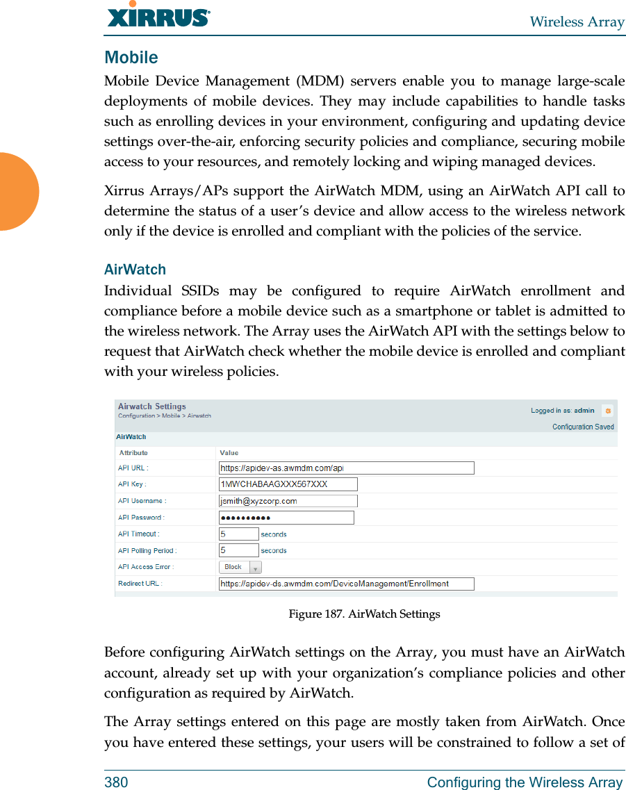
![Wireless Array446 The Command Line InterfacemdmThe mdm command [MyAP(config)# mdm] is used to configure Mobile Device Management Server settings. See also, “Mobile” on page 380. Command Descriptionairwatch api Set Location Server customer key.FORMAT:mdm airwatch api The following types of settings may be configured in management mode:access-error Set AirWatch API access error action key Set AirWatch API keypassword Set AirWatch API passwordpoll-period Set AirWatch API poll periodtimeout Set AirWatch API timeouturl Set AirWatch API URLusername Set AirWatch API usernameredirect-url Set URL to redirect clients to.FORMAT:mdm airwatch redirect-url <URL-string>](https://usermanual.wiki/Cambium-Networks/XI-AC1300.Part-2/User-Guide-2284763-Page-290.png)
![Wireless ArrayThe Command Line Interface 447more The more command [MyAP(config)# more] is used to turn terminal pagination ON or OFF.Command Descriptionoff Turn OFF terminal pagination.FORMAT:more offon Turn ON terminal pagination.FORMAT:more on](https://usermanual.wiki/Cambium-Networks/XI-AC1300.Part-2/User-Guide-2284763-Page-291.png)
![Wireless Array448 The Command Line InterfacenetflowThe netflow command [MyAP(config-netflow)#] is used to enable or disable, or configure sending IP flow information (traffic statistics) to the collector you specify.Command Descriptiondisable Disable netflow.FORMAT:netflow disableenable Enable netflow.FORMAT:netflow enableoff Disable netflow.FORMAT:netflow offon Enable netflow.FORMAT:netflow oncollector Set the netflow collector IP address or fully qualified domain name (host.domain). Only one collector may be set. If port is not specified, the default is 2055. FORMAT:netflow collector host {<ip-addr> | <domain>} [port <port#>]](https://usermanual.wiki/Cambium-Networks/XI-AC1300.Part-2/User-Guide-2284763-Page-292.png)
![Wireless ArrayThe Command Line Interface 449no The no command [MyAP(config)# no] is used to disable a selected element or set the element to its default value.Command Descriptionacl Disable the Access Control List.FORMAT:no acldot11a Disable all 802.11an IAPs (radios).FORMAT:no dot11adot11bg Disable all 802.11bgn IAPs (radios).FORMAT:no dot11bghttps Disable https access.FORMAT:no httpsintrude-detect Disable intrusion detection.FORMAT:no intrude-detectmanagement Disable management on all Ethernet interfaces.FORMAT:no managementmore Disable terminal pagination.FORMAT:no morentp Disable the NTP server.FORMAT:no ntp](https://usermanual.wiki/Cambium-Networks/XI-AC1300.Part-2/User-Guide-2284763-Page-293.png)
![Wireless Array452 The Command Line Interfacequit The quit command [MyAP(config)# quit] is used to exit the Command Line Interface.authentication-server The radius-server command [MyAP(config-authserver)#] is used to configure the external and internal RADIUS server parameters.Command Description<cr> Exit the Command Line Interface.FORMAT:quitIf you have made any configuration changes and your changes have not been saved, you are prompted to save your changes to Flash.At the prompt, answer Yes to save your changes, or answer No to discard your changes.Command Descriptionexternal Configure an external RADIUS server.FORMAT:authentication-server externalTo configure a RADIUS server (primary, secondary, or accounting server, by IP address or host name), and the reporting interval use:authentication-server external accountinginternal Configure the external RADIUS server.FORMAT: add active directoryauthentication-server internaluse Choose the active RADIUS server (either external or internal).FORMAT:authentication-server use external (or internal)](https://usermanual.wiki/Cambium-Networks/XI-AC1300.Part-2/User-Guide-2284763-Page-296.png)
![Wireless ArrayThe Command Line Interface 453reboot The reboot command [MyAP(config)# reboot] is used to reboot the Array. If you have unsaved changes, the command will notify you and give you a chance to cancel the reboot. reset The reset command [MyAP(config)# reset] is used to reset all settings to their default values then reboot the Array.Command Description<cr> Reboot the Array.FORMAT:rebootdelay Reboot the Array after a delay of 1 to 60 seconds.FORMAT:reboot delay [n]Command Description<cr> Reset all configuration parameters to their factory default values.FORMAT:resetThe Array is rebooted automatically.preserve-ip-settingsPreserve all ethernet and VLAN settings and reset all other configuration parameters to their factory default values.FORMAT:reset preserve-ip-settingsThe Array is rebooted automatically.](https://usermanual.wiki/Cambium-Networks/XI-AC1300.Part-2/User-Guide-2284763-Page-297.png)
![Wireless Array454 The Command Line Interfacerestore The restore command [MyAP(config)# restore] is used to restore configuration to a version that was previously saved locally. Command Description?Use this to display the list of available config files.FORMAT:restore ?<filename> Enter the name of the locally saved configuration to restore.FORMAT:restore <config-filename>](https://usermanual.wiki/Cambium-Networks/XI-AC1300.Part-2/User-Guide-2284763-Page-298.png)
![Wireless ArrayThe Command Line Interface 455roaming-assistThe roaming-assist command [MyAP(config)# roaming-assist] is used to configure roaming assistance settings. See also, “Roaming Assist” on page 356. Command Descriptiondata-rate Set minimum packet data rate before roaming, in Mbps.FORMAT:roaming-assist data-rate <1-99> devices Set device types or classes to assist.FORMAT:roaming-assist devices all | unidentified | DEVICE-CLASS <ID-string> | DEVICE-TYPE <ID-string>disable Disable roaming assist.FORMAT:roaming-assist disableenable Enable roaming assist.FORMAT:roaming-assist enableperiod Set roaming assist backoff period (seconds).FORMAT:roaming-assist period <#-seconds> threshold Set roaming RSSI threshold in db relative to RSSI of nearest Array.FORMAT:roaming-assist threshold <-50 to 50>](https://usermanual.wiki/Cambium-Networks/XI-AC1300.Part-2/User-Guide-2284763-Page-299.png)
![Wireless Array456 The Command Line Interfacerun-tests The run-tests command [MyAP(run-tests)#] is used to enter run-tests mode, which allows you to perform a range of tests on the Array.Command Description<cr> Enter run-tests mode.FORMAT:run-tests iperf Execute iperf utility.FORMAT:run-tests iperfkill-beacons Turn off beacons for selected single IAP.FORMAT:run-tests kill-beacons [off | iap-name] kill-probe-responses Turn off probe responses for selected single IAP.FORMAT:run-tests kill-probe-responses [off | iap-name] led LED test.FORMAT:run-tests led [flash | rotate] memtest Execute memory tests.FORMAT:run-tests memtestping Execute ping utility.FORMAT:run-tests ping [host-name | ip-addr]](https://usermanual.wiki/Cambium-Networks/XI-AC1300.Part-2/User-Guide-2284763-Page-300.png)
![Wireless ArrayThe Command Line Interface 457radius-ping Special ping utility to test the connection to a RADIUS server.FORMAT:run-tests radius-ping [external | ssid <ssidnum>] [primary | secondary] user <raduser> password <radpasswd> auth-type [CHAP | PAP]run-tests radius-ping [internal | server <radserver> port <radport> secret <radsecret> ] user <raduser> password <radpasswd> auth-type [CHAP | PAP]You may select a RADIUS server that you have already configured (ssid or external or internal) or specify another server. rlb Run manufacturing radio loopback test.FORMAT:run-tests rlb {optional command line switches}self-test Execute self-test.FORMAT:run-tests self-test {logfile-name (optional)]site-survey Enable or disable site survey mode.FORMAT:run-tests site-survey [on | off | enable | disable] ssh Execute ssh utility.FORMAT:run-tests ssh [hostname | ip-addr] [command-line-switches (optional)] tcpdump Execute tcpdump utility to dump traffic for selected interface or VLAN. Supports 802.11 headers.FORMAT:run-tests tcpdumpCommand Description](https://usermanual.wiki/Cambium-Networks/XI-AC1300.Part-2/User-Guide-2284763-Page-301.png)
![Wireless Array458 The Command Line Interfacesecurity The security command [MyAP(config-security)#] is used to establish the security parameters for the Array.telnet Execute telnet utility.FORMAT:run-tests telnet [hostname | ip-addr] [command-line-switches (optional)] traceroute Execute traceroute utility.FORMAT:run-tests traceroute [host-name | ip-addr]Command Descriptionwep Set the WEP encryption parameters.FORMAT:security wepwpa Set the WEP encryption parameters.FORMAT:security wpaCommand Description](https://usermanual.wiki/Cambium-Networks/XI-AC1300.Part-2/User-Guide-2284763-Page-302.png)
![Wireless ArrayThe Command Line Interface 459snmp The snmp command [MyAP(config-snmp)#] is used to enable, disable, or configure SNMP.Command Descriptionv2 Enable SNMP v2.FORMAT:snmp v2v3 Enable SNMP v3.FORMAT:snmp v3trap Configure traps for SNMP. Up to four trap destinations may be configured, and you may specify whether to send traps for authentication failure. FORMAT:snmp trap](https://usermanual.wiki/Cambium-Networks/XI-AC1300.Part-2/User-Guide-2284763-Page-303.png)
![Wireless Array460 The Command Line Interfacessid The ssid command [MyAP(config-ssid)#] is used to establish your SSID parameters.Command Descriptionadd Add an SSID.FORMAT:ssid add [newssid]del Delete an SSID.FORMAT:ssid del [oldssid]edit Edit an existing SSID.FORMAT:ssid edit [existingssid]reset Delete all SSIDs and restore the default SSID.FORMAT:ssid reset](https://usermanual.wiki/Cambium-Networks/XI-AC1300.Part-2/User-Guide-2284763-Page-304.png)
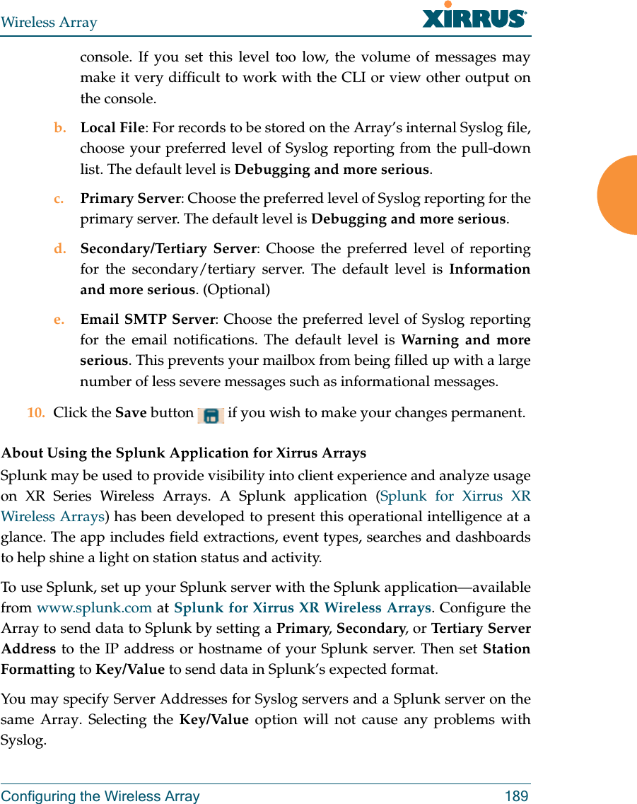
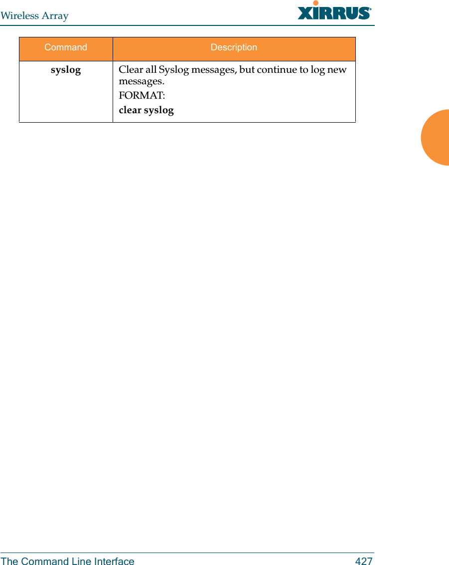
![Wireless ArrayThe Command Line Interface 461syslog The syslog command [MyAP(config-syslog)#] is used to enable, disable, or configure the Syslog server.Command Descriptionconsole Enable or disable the display of Syslog messages on the console, and set the level to be displayed. All messages at this level and lower (i.e., more severe) will be displayed.FORMAT:syslog console [on/off] level [0-7]disable Disable the Syslog server.FORMAT:syslog disableemail Disable the Syslog server.FORMAT:syslog email from [email-from-address] level [0-7] password [email-acct-password] server [email-server-IPaddr] test [test-msg-text] to-list [recipient-email-addresses] user [email-acct-username]enable Enable the Syslog server.FORMAT:syslog enablelocal-file Set the size and/or severity level (all messages at this level and lower will be logged).FORMAT:syslog local-file size [1-500] level [0-7]no Disable the selected feature.FORMAT:syslog no [feature]](https://usermanual.wiki/Cambium-Networks/XI-AC1300.Part-2/User-Guide-2284763-Page-305.png)
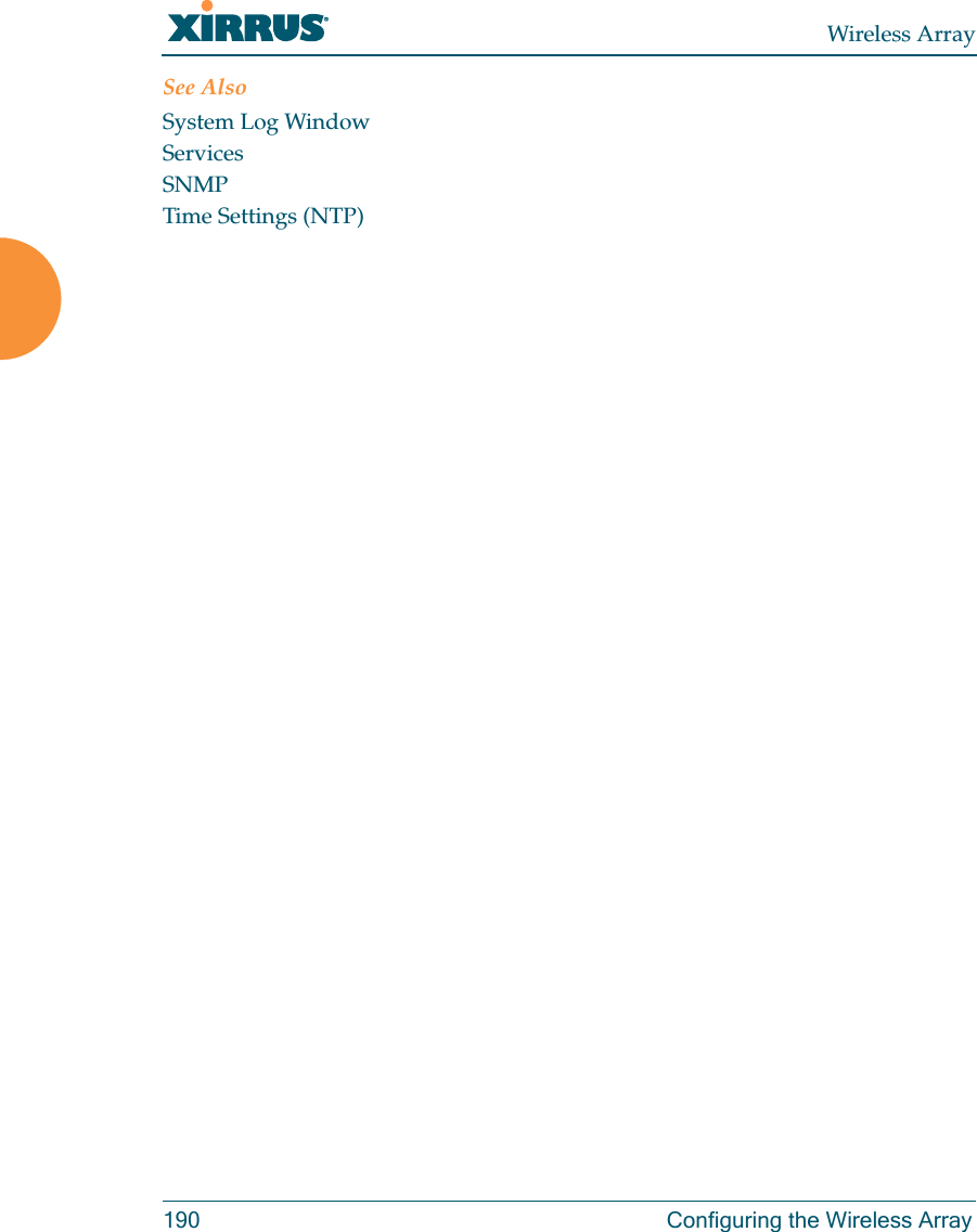
![Wireless Array462 The Command Line Interfacetunnel The tunnel command [MyAP(config-tunnel)#] is used to establish your tunnel parameters.off Disable the Syslog server.FORMAT:syslog offon Enable the Syslog server.FORMAT:syslog onprimary Set the IP address of the primary Syslog server and/or the severity level of messages to be logged.FORMAT:syslog primary [1.2.3.4] level [0-7]secondary Set the IP address of the secondary (backup) Syslog server and/or the severity level of messages to be logged.FORMAT:syslog primary [1.2.3.4] level [0-7]Command Descriptionadd Add a tunnel.FORMAT:tunnel add [newtunnel]delete Delete a tunnel.FORMAT:tunnel delete [oldtunnel]Command Description](https://usermanual.wiki/Cambium-Networks/XI-AC1300.Part-2/User-Guide-2284763-Page-306.png)
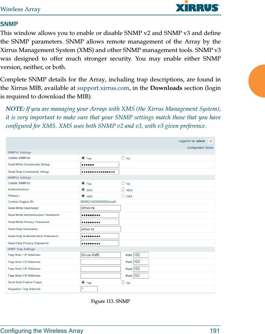
![Wireless ArrayThe Command Line Interface 463uptime The uptime command [MyAP(config)# uptime] is used to display the elapsed time since you last rebooted the Array. vlan The vlan command [MyAP(config-vlan)#] is used to establish your VLAN parameters.edit Modify an existing tunnel.FORMAT:tunnel edit [existingtunnel]reset Delete all existing tunnels.FORMAT:tunnel resetCommand Description<cr> Display time since last reboot.FORMAT:uptimeCommand Descriptionadd Add a VLAN.FORMAT:vlan add [newvlan]default-route Assign a VLAN for the default route (for outbound management traffic).FORMAT:vlan default-route [defaultroute]Command Description](https://usermanual.wiki/Cambium-Networks/XI-AC1300.Part-2/User-Guide-2284763-Page-307.png)
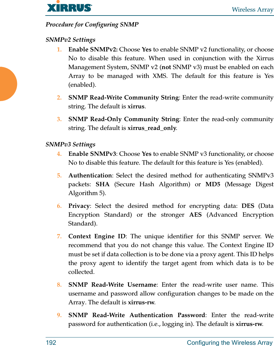
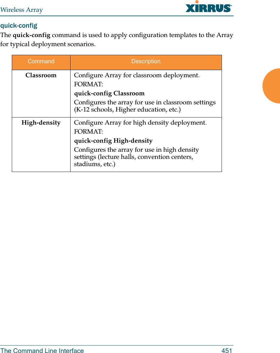
![Wireless Array464 The Command Line Interfacewifi-tag The wifi-tag command [MyAP(config-wifi-tag)#] is used to enable or disable Wi-Fi tag capabilities. When enabled, the Array listens for and collects information about Wi-Fi RFID tags sent on the designated channels. See also “Wi-Fi Tag” on page 183.delete Delete a VLAN.FORMAT:vlan delete [oldvlan]edit Modify an existing VLAN.FORMAT:vlan edit [existingvlan]native-vlan Assign a native VLAN (traffic is untagged).FORMAT:vlan native-vlan [nativevlan]no Disable the selected feature.FORMAT:vlan no [feature]reset Delete all existing VLANs.FORMAT:vlan resetCommand Descriptiondisable Disable wifi-tag.FORMAT:wifi-tag disableenable Enable wifi-tag.FORMAT:wifi-tag enableCommand Description](https://usermanual.wiki/Cambium-Networks/XI-AC1300.Part-2/User-Guide-2284763-Page-308.png)

![Wireless Array507Boot your Array and watch the progress messages. When Press space bar to exit to bootloader: is displayed, press the space bar. The rest of this procedure is performed using the bootloader. The following steps assume that you are running DHCP on your local network. 5. Type dhcp and hit return. This instructs the Array to obtain a DHCP address and use it during this boot in the bootloader environment. 6. Type dir and hit return to see what's currently in the compact flash. 7. Type del and hit return to delete the contents of the compact flash. 8. Type update server <TFTP-server-ip-addr> XS-5.x-xxxx.bin (the actual Xirrus file name will vary depending on Array model number and software version — use the file name from your software update) and hit return. The software update will be transferred to the Array's memory and will be written to the compact flash card. (See output below.)9. Type reset and hit return. Your Array will reboot, running your new version of software. Sample Output for the Upgrade Procedure:The user actions are highlighted in the output below, for clarity. Username: adminPassword: *****Xirrus-WiFi-Array# configureXirrus-WiFi-Array(config)# rebootAre you sure you want to reboot? [yes/no]: yesArray is being rebooted.Xirrus Boot Loader 1.0.0 (Oct 17 2006 - 13:11:42), Build: 2725Processor | Motorola PowerPC, PVR=80200020 SVR=80300020Board | Xirrus MPC8540 CPU BoardClocks | CPU : 825 MHz DDR : 330 MHz Local Bus: 41 MHz](https://usermanual.wiki/Cambium-Networks/XI-AC1300.Part-2/User-Guide-2284763-Page-351.png)
![Wireless Array508L1 cache | Data: 32 KB Inst: 32 KB Status : EnabledWatchdog | Enabled (5 secs)I2C Bus | 400 KHzDTT | CPU:34C RF0:34C RF1:34C RF2:27C RF3:29CRTC | Wed 2007-Nov-05 6:43:14 GMTSystem DDR | 256 MB, Unbuffered Non-ECC (2T)L2 cache | 256 KB, EnabledFLASH | 4 MB, CRC: OKFPGA | 2 Devices programmedPacket DDR | 256 MB, Unbuffered Non-ECC, EnabledNetwork | Mot FEC Mot TSEC1 [Primary] Mot TSEC2IDE Bus 0 | OKCFCard | 122 MB, Model: Hitachi XXM2.3.0Environment| 4 KB, InitializedIn: serialOut: serialErr: serialPress space bar to exit to bootloader: XBL>dhcp[DHCP ] Device : Mot TSEC1 1000BT Full Duplex[DHCP ] IP Addr : 192.168.39.195XBL>dir[CFCard] Directory of / Date Time Size File or Directory name----------- -------- -------- ---------------------------2007-Nov-05 6:01:56 29 lastboot2007-Apr-05 15:47:46 28210390 xs-3.1-0433.bak2007-Mar-01 16:39:42 storage/2007-Apr-05 15:56:38 28210430 xs-3.1-0440.bin2007-Mar-03 0:56:28 wpr/3 file(s), 2 dir(s)](https://usermanual.wiki/Cambium-Networks/XI-AC1300.Part-2/User-Guide-2284763-Page-352.png)
![Wireless Array509XBL>del * [CFCard] Delete : 2 file(s) deletedXBL>update server 192.168.39.102 xs-3.0-0425.bin[TFTP ] Device : Mot TSEC1 1000BT Full Duplex[TFTP ] Client : 192.168.39.195[TFTP ] Server : 192.168.39.102[TFTP ] File : xs-3.0-0425.bin[TFTP ] Address : 0x1000000[TFTP ] Loading : ##################################################[TFTP ] Loading : ##################################################[TFTP ] Loading : ###### done[TFTP ] Complete: 12.9 sec, 2.1 MB/sec[TFTP ] Bytes : 27752465 (1a77811 hex)[CFCard] File : xs-3.0-0425.bin[CFCard] Address : 0x1000000[CFCard] Saving : ############################################### done[CFCard] Complete: 137.4 sec, 197.2 KB/sec[CFCard] Bytes : 27752465 (1a77811 hex)XBL>reset[RESET ]Xirrus Boot Loader 1.0.0 (Oct 17 2006 - 13:11:42), Build: 2725Processor | Motorola PowerPC, PVR=80200020 SVR=80300020Board | Xirrus MPC8540 CPU BoardClocks | CPU : 825 MHz DDR : 330 MHz Local Bus: 41 MHzL1 cache | Data: 32 KB Inst: 32 KB Status : EnabledWatchdog | Enabled (5 secs)I2C Bus | 400 KHzDTT | CPU:33C RF0:32C RF1:31C RF2:26C RF3:27CRTC | Wed 2007-Nov-05 6:48:44 GMTSystem DDR | 256 MB, Unbuffered Non-ECC (2T)](https://usermanual.wiki/Cambium-Networks/XI-AC1300.Part-2/User-Guide-2284763-Page-353.png)
![Wireless Array510L2 cache | 256 KB, EnabledFLASH | 4 MB, CRC: OKFPGA | 2 Devices programmedPacket DDR | 256 MB, Unbuffered Non-ECC, EnabledNetwork | Mot FEC Mot TSEC1 [Primary] Mot TSEC2IDE Bus 0 | OKCFCard | 122 MB, Model: Hitachi XXM2.3.0Environment| 4 KB, InitializedIn: serialOut: serialErr: serialPress space bar to exit to bootloader: [CFCard] File : xs*.bin[CFCard] Address : 0x1000000[CFCard] Loading : ############################################### done[CFCard] Complete: 26.9 sec, 1.0 MB/sec[CFCard] Bytes : 27752465 (1a77811 hex)[Boot ] Address : 0x01000000[Boot ] Image : Verifying checksum .... OK[Boot ] Unzip : Multi-File Image .... OK[Boot ] Initrd : Loading RAMDisk Image[Boot ] Initrd : Verifying checksum .... OK[Boot ] Execute : Transferring control to OSInitializing hardware ........................................ OKXirrus Wi-Fi ArrayArrayOS Version 3.0-425Copyright (c) 2005-2007 Xirrus, Inc.http://www.xirrus.comUsername:](https://usermanual.wiki/Cambium-Networks/XI-AC1300.Part-2/User-Guide-2284763-Page-354.png)

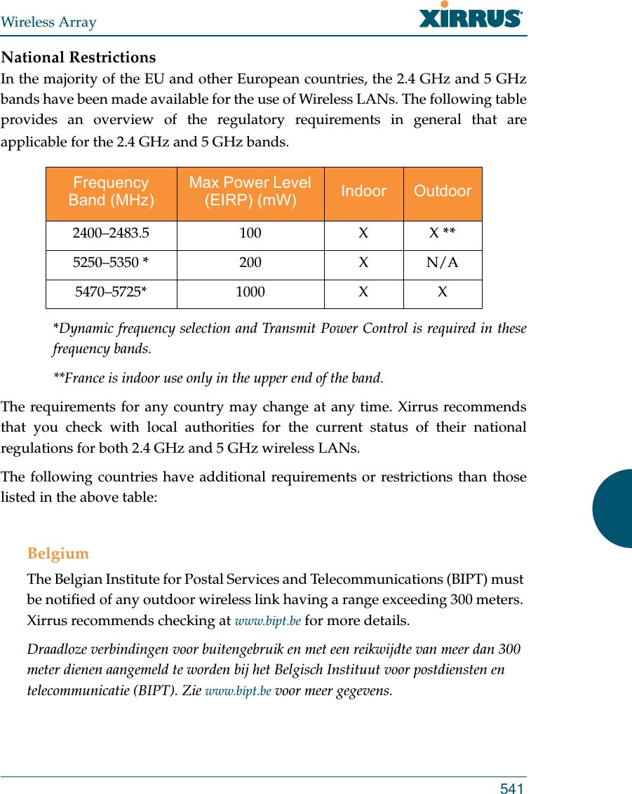
![Wireless Array515EU Directive 1999/5/EC Compliance InformationThis section contains compliance information for the Xirrus Wireless Array family of products. The compliance information contained in this section is relevant to the European Union and other countries that have implemented the EU Directive 1999/5/EC.Declaration of ConformityThis Appendix contains Notices, Warnings, and Compliance information forall Array models except for the XR-500/600 Series and models ending in H. For Notices, Warnings, and Compliance information for those models, see the notes at the beginning of this chapter. Cesky [Czech] Toto zahzeni je v souladu se základnimi požadavky a ostatnimi odpovidajcimi ustano veni mi Směrnice 1999/5/EC.Dansk [Danish] Dette udstyr er i overensstemmelse med de væsentlige krav og andre relevante bestemmelser i Direktiv 1999/5/EF.Deutsch [German] Dieses Gerat entspricht den grundlegenden Anforderungen und den weiteren entsprechenden Vorgaben der Richtinie 1999/5/EU.Eesti [Estonian] See seande vastab direktiivi 1999/5/EU olulistele nöuetele ja teistele as jakohastele sätetele.English This equipment is in compliance with the essential requirements and other relevant provisions of Directive 1999/5/EC.Español [Spain] Este equipo cump le con los requisitos esenciales asi como con otras disposiciones de la Directiva 1999/5/CE.Ελληνυκη [Greek] Αυτόζ ο εξοπλτσμόζ είναι σε συμμόρφωση με τιζ ουσιώδειζ απαιτήσειζ και ύλλεζ σχετικέζ διατάξειζ τηζ Οδηγιαζ 1999/5/EC.](https://usermanual.wiki/Cambium-Networks/XI-AC1300.Part-2/User-Guide-2284763-Page-359.png)
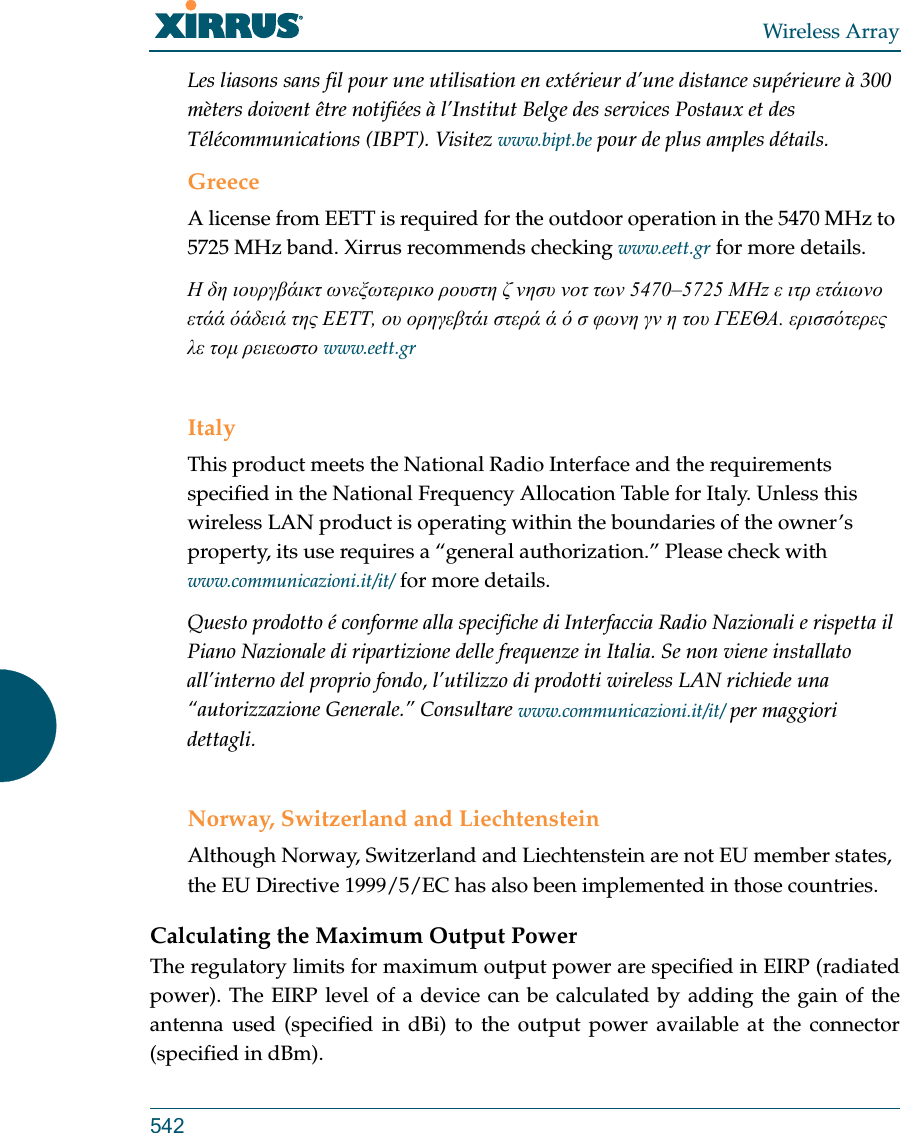
![Wireless Array516Français [French] Cet appareil est conforme aux exigences essentielles et aux autres dispositions pertinentes de la Directive 1999/5/EC.ĺslenska [Icelandic] Þetta tæki er samkvæmt grunnkröfum og öðrum viðeigandi ákvæðum Tilskipunar 1999/5/EC.Italiano [Italian] Questo apparato é conforme ai requisiti essenziali ed agli altri principi sanciti dalla Direttiva 1999/5/CE.Latviski [Latvian] Šī iekārta atbilst Direktīvas 1999/5/EK būtiskajāprasībām un citiem ar to saistītajiem noteikumiem.Lietuvių [Lithuanian] Šis įrenginys tenkina 1995/5/EB Direktyvos esminius reikalavimus ir kitas šios direktyvos nuostatas.Nederlands [Dutch] Dit apparant voldoet aan de essentiele eisen en andere van toepassing zijnde bepalingen van de Richtlijn 1995/5/EC.Malti [Maltese] Dan l-apparant huwa konformi mal-htigiet essenzjali u l-provedimenti l-ohra rilevanti tad-Direttiva 1999/5/EC.Margyar [Hungarian] Ez a készülék teljesiti az alapvetö követelményeket és más 1999/5/EK irányelvben meghatározott vonatkozó rendelkezéseket.Norsk [Norwegian] Dette utstyret er i samsvar med de grunnleggende krav og andre relevante bestemmelser i EU-direktiv 1999/5/EF.Polski [Polish] Urządzenie jest zgodne z ogólnymi wymaganiami oraz sczególnymi mi warunkami określony mi Dyrektywą. UE:1999/5/EC.Portuguès [Portuguese] Este equipamento está em conformidade com os requisitos essenciais e outras provisões relevantes da Directiva 1999/5/EC.](https://usermanual.wiki/Cambium-Networks/XI-AC1300.Part-2/User-Guide-2284763-Page-360.png)
![Wireless Array517Assessment CriteriaThe following standards were applied during the assessment of the product against the requirements of the Directive 1999/5/EC:Radio: EN 301 893 and EN 300 328 (if applicable)EMC: EN 301 489-1 and EN 301 489-17Safety: EN 50371 to EN 50385 and EN 60601CE MarkingFor the Xirrus Wireless Array, the CE mark and Class-2 identifier opposite are affixed to the equipment and its packaging: Russian Certification MarkingFor the Xirrus XR-500, XR-520H, XR-2000, and XR-4000 Series Wireless Arrays, the approval mark is affixed to the equipment: Slovensko [Slovenian] Ta naprava je skladna z bistvenimi zahtevami in ostalimi relevantnimi popoji Direktive 1999/5/EC.Slovensky [Slovak] Toto zariadenie je v zhode so základnými požadavkami a inými prislušnými nariadeniami direktiv: 1999/5/EC.Suomi [Finnish] Tämä laite täyttää direktiivin 1999/5//EY olennaiset vaatimukset ja on siinä asetettujen muiden laitetta koskevien määräysten mukainen.Svenska [Swedish] Denna utrustning är i överensstämmelse med de väsentliga kraven och andra relevanta bestämmelser i Direktiv 1999/5/EC.](https://usermanual.wiki/Cambium-Networks/XI-AC1300.Part-2/User-Guide-2284763-Page-361.png)


![Wireless Array5273.0 LIMITED WARRANTY AND LIMITATION OF LIABILITY 3.1 Limited Warranty & Exclusions. Licensor warrants that the Software will perform in substantial accordance with the specifications therefore set forth in the Documentation for a period of ninety [90] days after Customer's acceptance of the terms of this Agreement with respect to the Software (“Warranty Period”). If during the Warranty Period the Software or Product does not perform as warranted, Licensor shall, at its option, correct the relevant Product and/or Software giving rise to such breach of performance or replace such Product and/or Software free of charge. THE FOREGOING ARE CUSTOMER'S SOLE AND EXCLUSIVE REMEDIES FOR BREACH OF THE FOREGOING WARRANTY. THE WARRANTY SET FORTH ABOVE IS MADE TO AND FOR THE BENEFIT OF CUSTOMER ONLY. The warranty will apply only if (i) the Software has been used at all times and in accordance with the instructions for use set forth in the Documentation and this Agreement; (ii) no modification, alteration or addition has been made to the Software by persons other than Licensor or Licensor's authorized representative; and (iii) the Software or Product on which the Software is installed has not been subject to any unusual electrical charge. 3.2 DISCLAIMER. EXCEPT AS EXPRESSLY STATED IN THIS SECTION 3, ALL ADDITIONAL CONDITIONS, REPRESENTATIONS, AND WARRANTIES, WHETHER IMPLIED, STATUTORY OR OTHERWISE, INCLUDING, WITHOUT LIMITATION, ANY IMPLIED WARRANTIES OR CONDITIONS OF MERCHANTABILITY, FITNESS FOR A PARTICULAR PURPOSE, SATISFACTORY QUALITY, ACCURACY, AGAINST INFRINGEMENT OR ARISING FROM A COURSE OF DEALING, USAGE, OR TRADE PRACTICE, ARE HEREBY DISCLAIMED BY LICENSOR AND ITS SUPPLIERS. THIS DISCLAIMER SHALL APPLY EVEN IF ANY EXPRESS WARRANTY AND LIMITED REMEDY OFFERED BY LICENSOR FAILS OF ITS ESSENTIAL PURPOSE. ALL WARRANTIES PROVIDED BY LICENSOR ARE SUBJECT TO THE LIMITATIONS OF LIABILITY SET FORTH IN THIS AGREEMENT. 3.3 HAZARDOUS APPLICATIONS. THE SOFTWARE IS NOT DESIGNED OR INTENDED FOR USE IN HAZARDOUS ENVIRONMENTS REQUIRING FAIL SAFE PERFORMANCE, SUCH AS IN THE OPERATION OF A NUCLEAR FACILITY, AIRCRAFT NAVIGATION OR COMMUNICATIONS SYSTEMS, AIR TRAFFIC CONTROLS OR OTHER DEVICES OR SYSTEMS IN WHICH A MALFUNCTION OF THE SOFTWARE WOULD RESULT IN FORSEEABLE RISK OF INJURY OR DEATH TO THE OPERATOR OF THE DEVICE OR SYSTEM OR TO OTHERS (“HAZARDOUS APPLICATIONS”). CUSTOMER ASSUMES ANY AND ALL RISKS, INJURIES, LOSSES, CLAIMS AND ANY OTHER LIABILITIES ARISING OUT OF THE USE OF THE SOFTWARE IN ANY HAZARDOUS APPLICATIONS.](https://usermanual.wiki/Cambium-Networks/XI-AC1300.Part-2/User-Guide-2284763-Page-371.png)


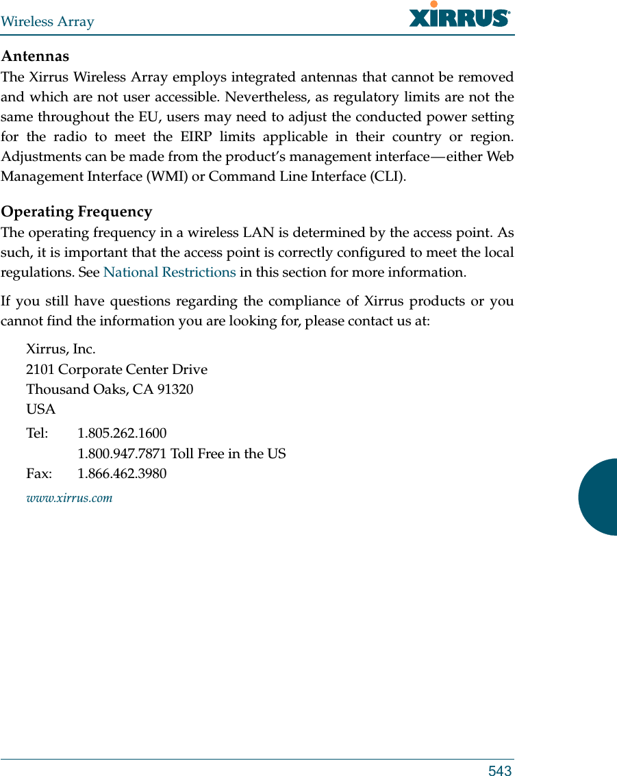
![Wireless Array537EU Directive 1999/5/EC Compliance InformationThis section contains compliance information for the Xirrus Wireless Array family of products. The compliance information contained in this section is relevant to the European Union and other countries that have implemented the EU Directive 1999/5/EC.Declaration of ConformityThis Appendix contains Notices, Warnings, and Compliance information forthe XR500/600 Series only. For other models, see the notes under “Appendix C: Notices (Arrays except XR-500/600 and -H Models)” on page 511. Cesky [Czech] Toto zahzeni je v souladu se základnimi požadavky a ostatnimi odpovidajcimi ustano veni mi Směrnice 1999/5/EC.Dansk [Danish] Dette udstyr er i overensstemmelse med de væsentlige krav og andre relevante bestemmelser i Direktiv 1999/5/EF.Deutsch [German] Dieses Gerat entspricht den grundlegenden Anforderungen und den weiteren entsprechenden Vorgaben der Richtinie 1999/5/EU.Eesti [Estonian] See seande vastab direktiivi 1999/5/EU olulistele nöuetele ja teistele as jakohastele sätetele.English This equipment is in compliance with the essential requirements and other relevant provisions of Directive 1999/5/EC.Español [Spain] Este equipo cump le con los requisitos esenciales asi como con otras disposiciones de la Directiva 1999/5/CE.Ελληνυκη [Greek] Αυτόζ ο εξοπλτσμόζ είναι σε συμμόρφωση με τιζ ουσιώδειζ απαιτήσειζ και ύλλεζ σχετικέζ διατάξειζ τηζ Οδηγιαζ 1999/5/EC.](https://usermanual.wiki/Cambium-Networks/XI-AC1300.Part-2/User-Guide-2284763-Page-381.png)
![Wireless Array538Français [French] Cet appareil est conforme aux exigences essentielles et aux autres dispositions pertinentes de la Directive 1999/5/EC.ĺslenska [Icelandic] Þetta tæki er samkvæmt grunnkröfum og öðrum viðeigandi ákvæðum Tilskipunar 1999/5/EC.Italiano [Italian] Questo apparato é conforme ai requisiti essenziali ed agli altri principi sanciti dalla Direttiva 1999/5/CE.Latviski [Latvian] Šī iekārta atbilst Direktīvas 1999/5/EK būtiskajāprasībām un citiem ar to saistītajiem noteikumiem.Lietuvių [Lithuanian] Šis įrenginys tenkina 1995/5/EB Direktyvos esminius reikalavimus ir kitas šios direktyvos nuostatas.Nederlands [Dutch] Dit apparant voldoet aan de essentiele eisen en andere van toepassing zijnde bepalingen van de Richtlijn 1995/5/EC.Malti [Maltese] Dan l-apparant huwa konformi mal-htigiet essenzjali u l-provedimenti l-ohra rilevanti tad-Direttiva 1999/5/EC.Margyar [Hungarian] Ez a készülék teljesiti az alapvetö követelményeket és más 1999/5/EK irányelvben meghatározott vonatkozó rendelkezéseket.Norsk [Norwegian] Dette utstyret er i samsvar med de grunnleggende krav og andre relevante bestemmelser i EU-direktiv 1999/5/EF.Polski [Polish] Urządzenie jest zgodne z ogólnymi wymaganiami oraz sczególnymi mi warunkami określony mi Dyrektywą. UE:1999/5/EC.Portuguès [Portuguese] Este equipamento está em conformidade com os requisitos essenciais e outras provisões relevantes da Directiva 1999/5/EC.](https://usermanual.wiki/Cambium-Networks/XI-AC1300.Part-2/User-Guide-2284763-Page-382.png)
![Wireless Array539Assessment CriteriaThe following standards were applied during the assessment of the product against the requirements of the Directive 1999/5/EC:Radio: EN 301 893 and EN 300 328 (if applicable)EMC: EN 301 489-1 and EN 301 489-17Safety: EN 50371 to EN 50385 and EN 60601CE MarkingFor the Xirrus Wireless Array, the CE mark and Class-2 identifier opposite are affixed to the equipment and its packaging: Russian Certification MarkingFor the Xirrus XR-500, XR-520H, XR-2000, and XR-4000 Series Wireless Arrays, the approval mark is affixed to the equipment: Slovensko [Slovenian] Ta naprava je skladna z bistvenimi zahtevami in ostalimi relevantnimi popoji Direktive 1999/5/EC.Slovensky [Slovak] Toto zariadenie je v zhode so základnými požadavkami a inými prislušnými nariadeniami direktiv: 1999/5/EC.Suomi [Finnish] Tämä laite täyttää direktiivin 1999/5//EY olennaiset vaatimukset ja on siinä asetettujen muiden laitetta koskevien määräysten mukainen.Svenska [Swedish] Denna utrustning är i överensstämmelse med de väsentliga kraven och andra relevanta bestämmelser i Direktiv 1999/5/EC.](https://usermanual.wiki/Cambium-Networks/XI-AC1300.Part-2/User-Guide-2284763-Page-383.png)

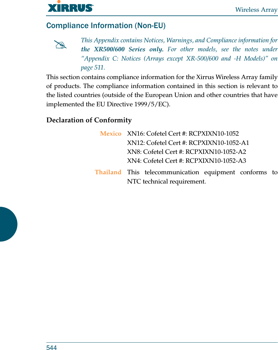
![Wireless Array5493.0 LIMITED WARRANTY AND LIMITATION OF LIABILITY 3.1 Limited Warranty & Exclusions. Licensor warrants that the Software will perform in substantial accordance with the specifications therefore set forth in the Documentation for a period of ninety [90] days after Customer's acceptance of the terms of this Agreement with respect to the Software (“Warranty Period”). If during the Warranty Period the Software or Product does not perform as warranted, Licensor shall, at its option, correct the relevant Product and/or Software giving rise to such breach of performance or replace such Product and/or Software free of charge. THE FOREGOING ARE CUSTOMER'S SOLE AND EXCLUSIVE REMEDIES FOR BREACH OF THE FOREGOING WARRANTY. THE WARRANTY SET FORTH ABOVE IS MADE TO AND FOR THE BENEFIT OF CUSTOMER ONLY. The warranty will apply only if (i) the Software has been used at all times and in accordance with the instructions for use set forth in the Documentation and this Agreement; (ii) no modification, alteration or addition has been made to the Software by persons other than Licensor or Licensor's authorized representative; and (iii) the Software or Product on which the Software is installed has not been subject to any unusual electrical charge. 3.2 DISCLAIMER. EXCEPT AS EXPRESSLY STATED IN THIS SECTION 3, ALL ADDITIONAL CONDITIONS, REPRESENTATIONS, AND WARRANTIES, WHETHER IMPLIED, STATUTORY OR OTHERWISE, INCLUDING, WITHOUT LIMITATION, ANY IMPLIED WARRANTIES OR CONDITIONS OF MERCHANTABILITY, FITNESS FOR A PARTICULAR PURPOSE, SATISFACTORY QUALITY, ACCURACY, AGAINST INFRINGEMENT OR ARISING FROM A COURSE OF DEALING, USAGE, OR TRADE PRACTICE, ARE HEREBY DISCLAIMED BY LICENSOR AND ITS SUPPLIERS. THIS DISCLAIMER SHALL APPLY EVEN IF ANY EXPRESS WARRANTY AND LIMITED REMEDY OFFERED BY LICENSOR FAILS OF ITS ESSENTIAL PURPOSE. ALL WARRANTIES PROVIDED BY LICENSOR ARE SUBJECT TO THE LIMITATIONS OF LIABILITY SET FORTH IN THIS AGREEMENT. 3.3 HAZARDOUS APPLICATIONS. THE SOFTWARE IS NOT DESIGNED OR INTENDED FOR USE IN HAZARDOUS ENVIRONMENTS REQUIRING FAIL SAFE PERFORMANCE, SUCH AS IN THE OPERATION OF A NUCLEAR FACILITY, AIRCRAFT NAVIGATION OR COMMUNICATIONS SYSTEMS, AIR TRAFFIC CONTROLS OR OTHER DEVICES OR SYSTEMS IN WHICH A MALFUNCTION OF THE SOFTWARE WOULD RESULT IN FORSEEABLE RISK OF INJURY OR DEATH TO THE OPERATOR OF THE DEVICE OR SYSTEM OR TO OTHERS (“HAZARDOUS APPLICATIONS”). CUSTOMER ASSUMES ANY AND ALL RISKS, INJURIES, LOSSES, CLAIMS AND ANY OTHER LIABILITIES ARISING OUT OF THE USE OF THE SOFTWARE IN ANY HAZARDOUS APPLICATIONS.](https://usermanual.wiki/Cambium-Networks/XI-AC1300.Part-2/User-Guide-2284763-Page-393.png)