Cambium Networks XI-N300 802.11abgn 2x2 Module User Manual xirrus PDF

Xirrus, Inc. 802.11abgn 2x2 Module xirrus PDF
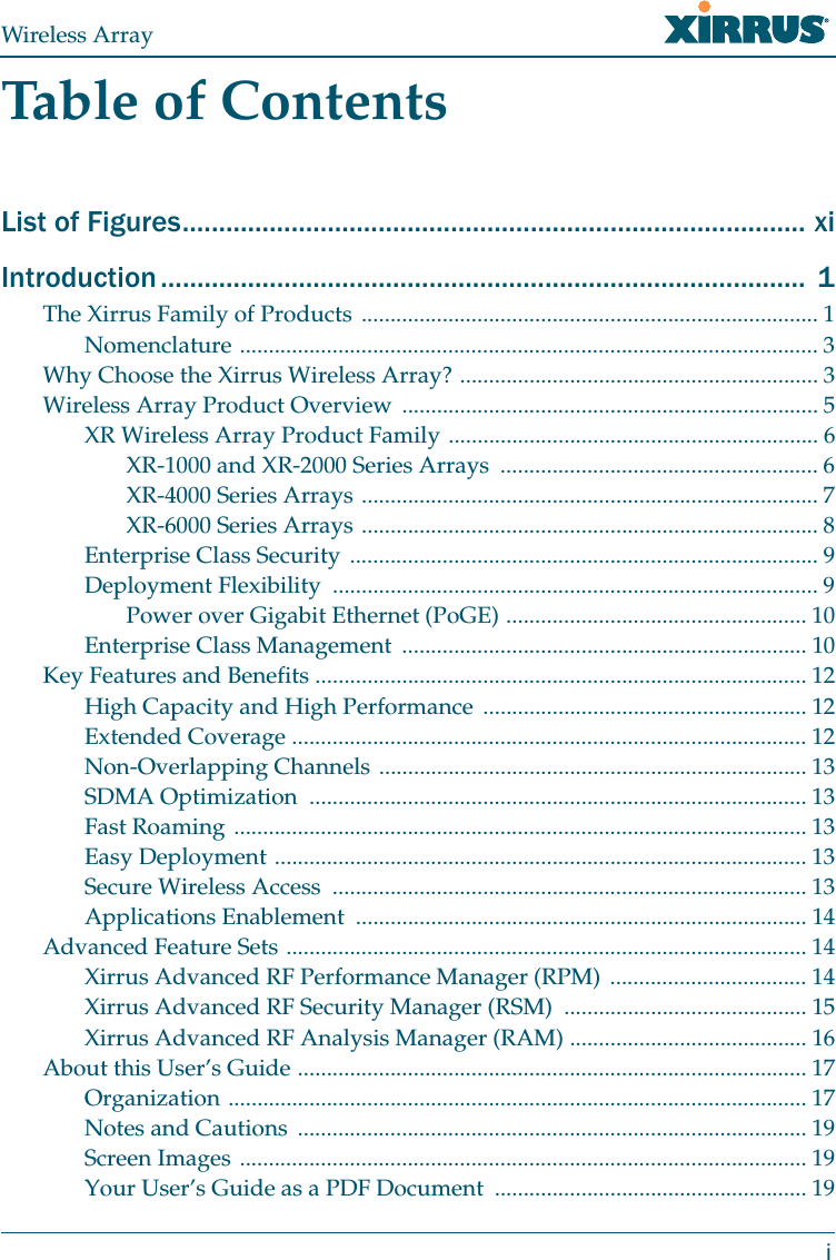
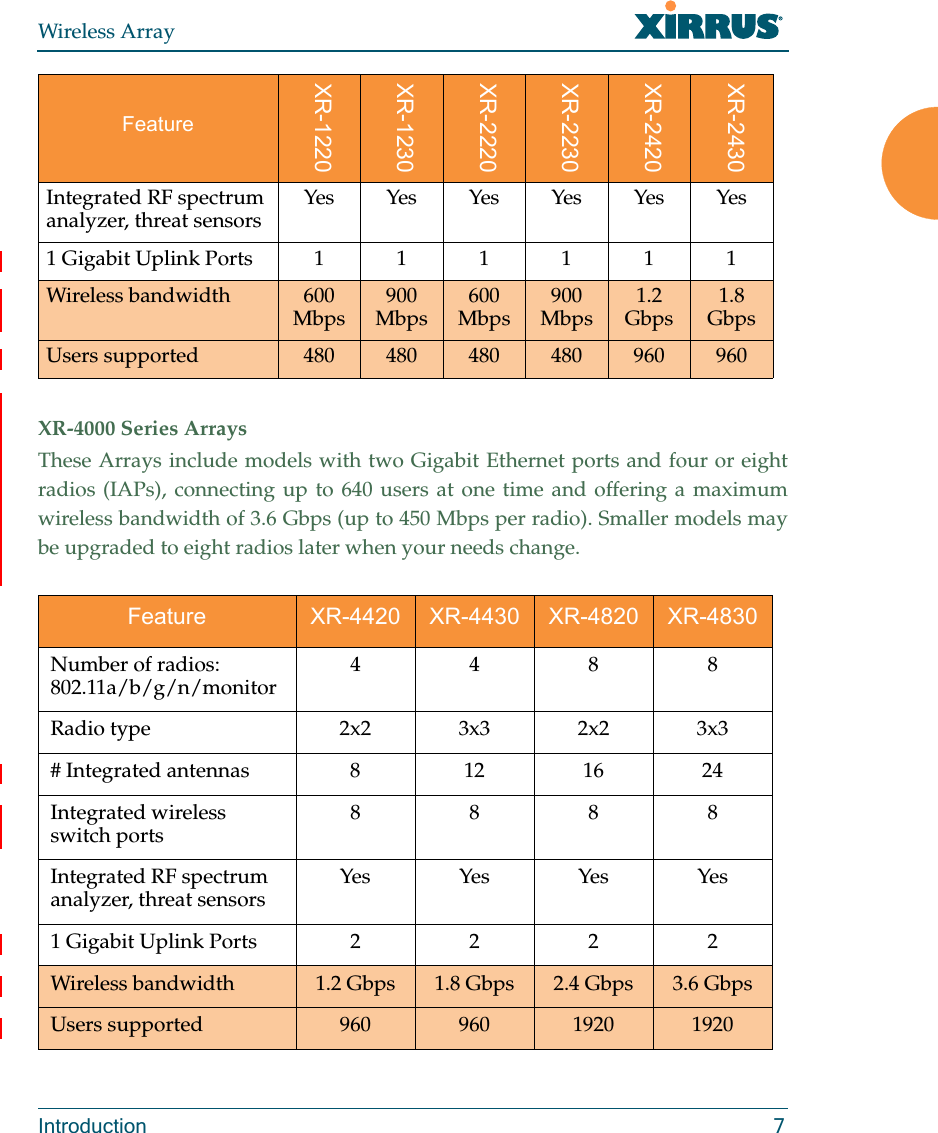
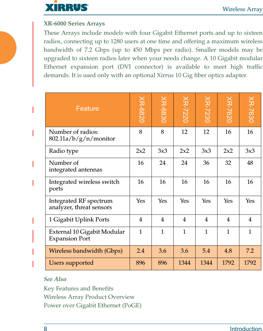
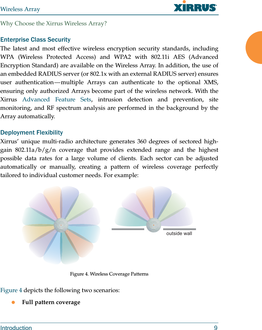
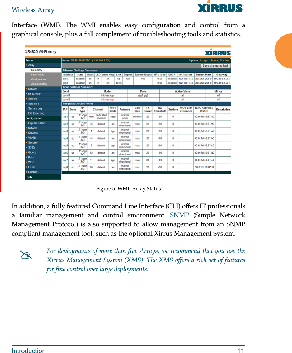
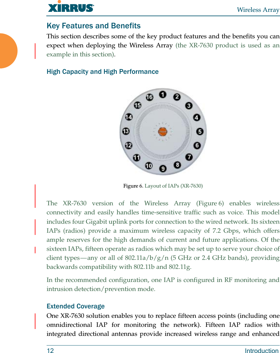
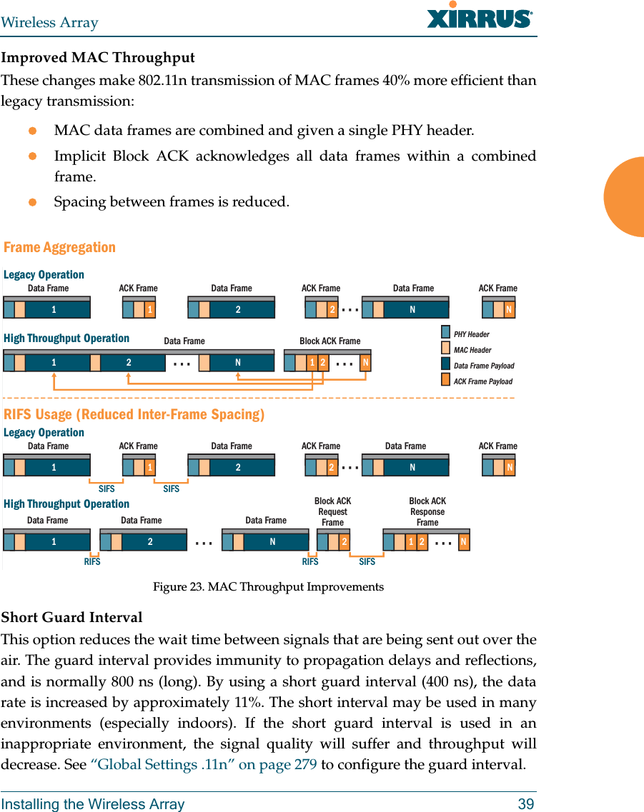
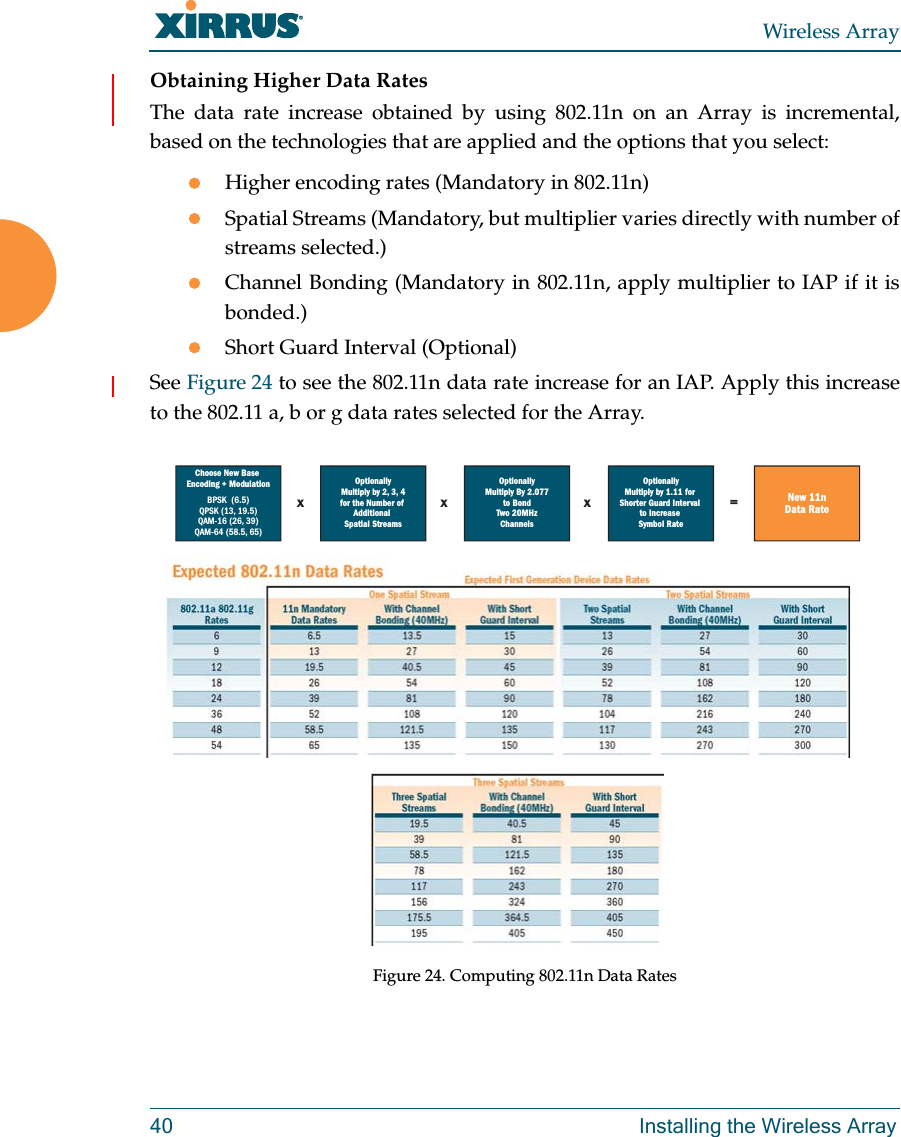
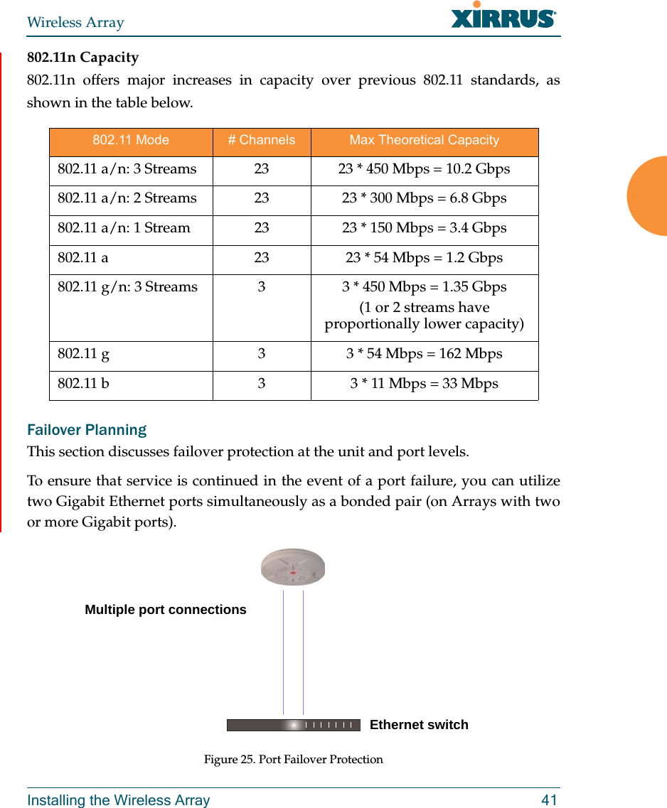
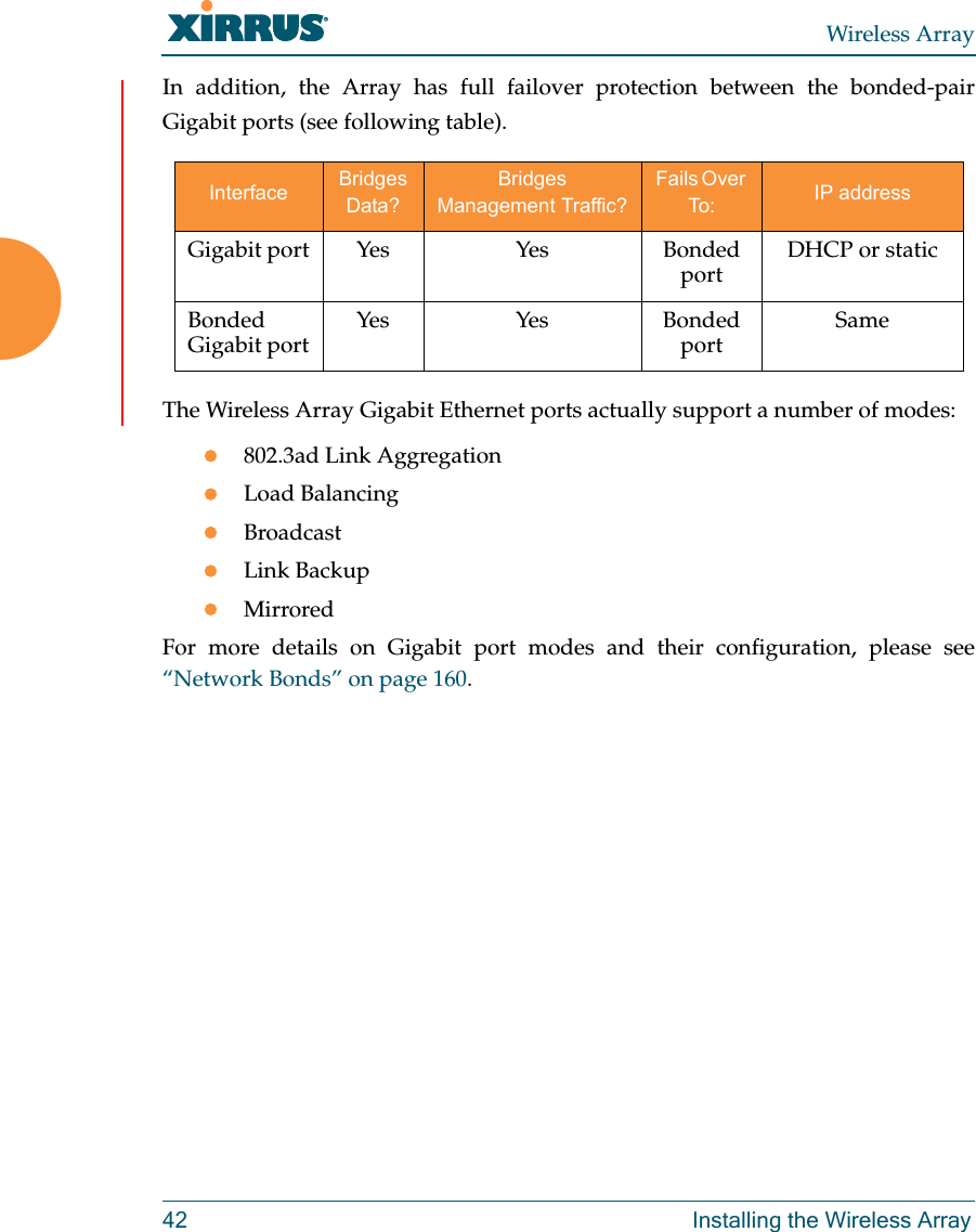
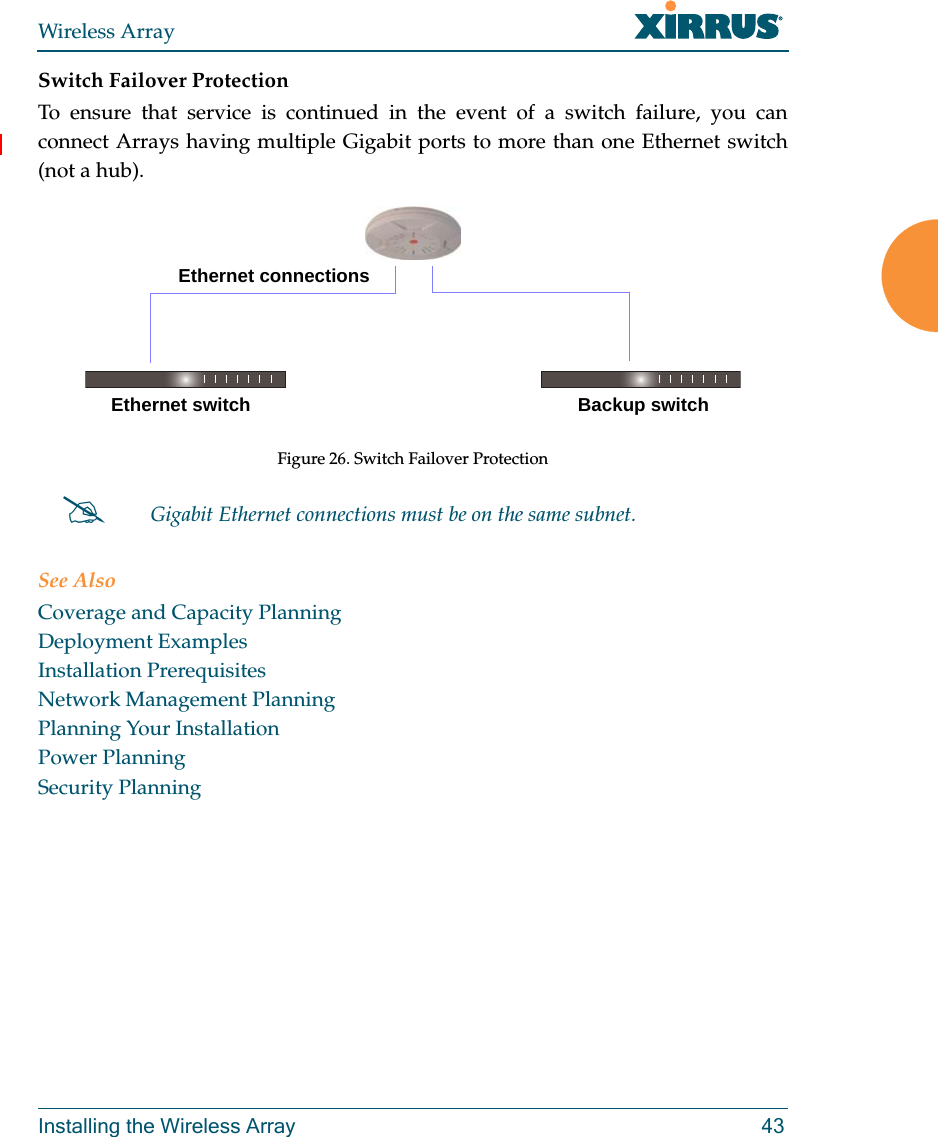
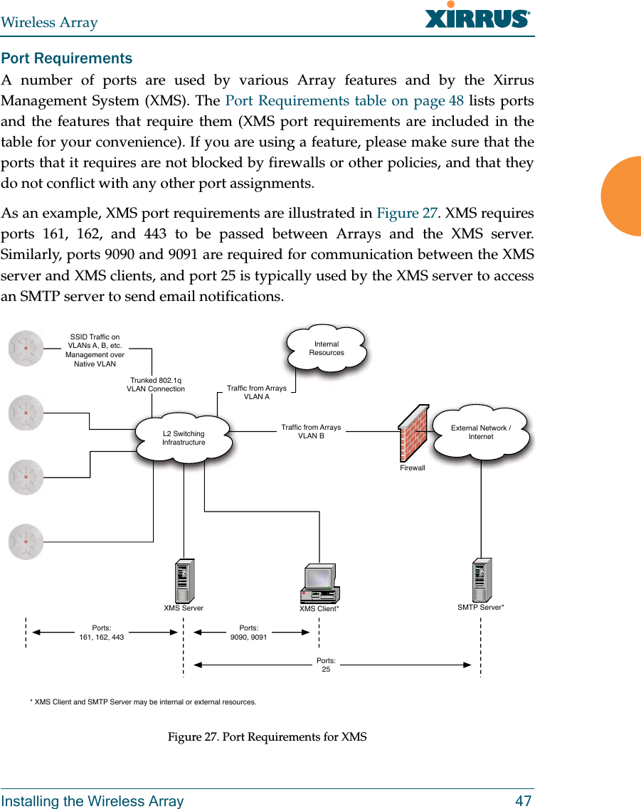
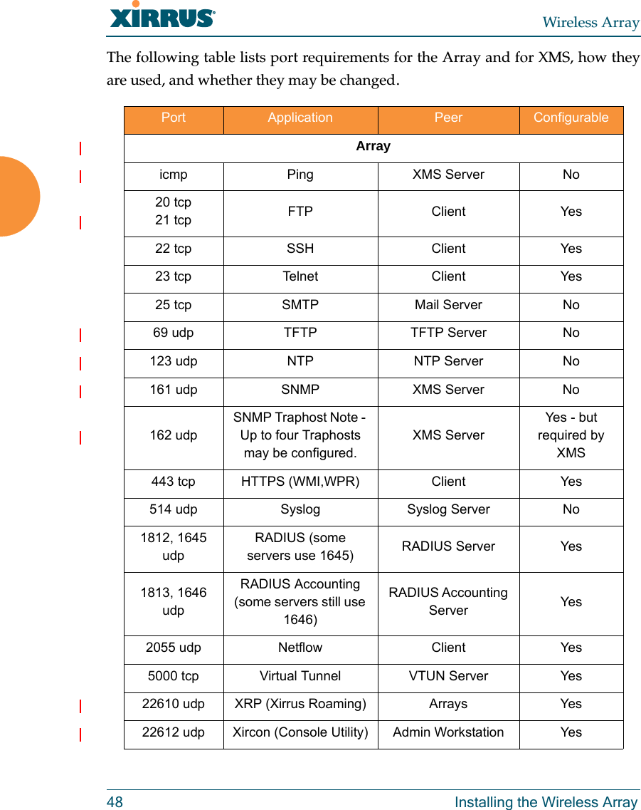
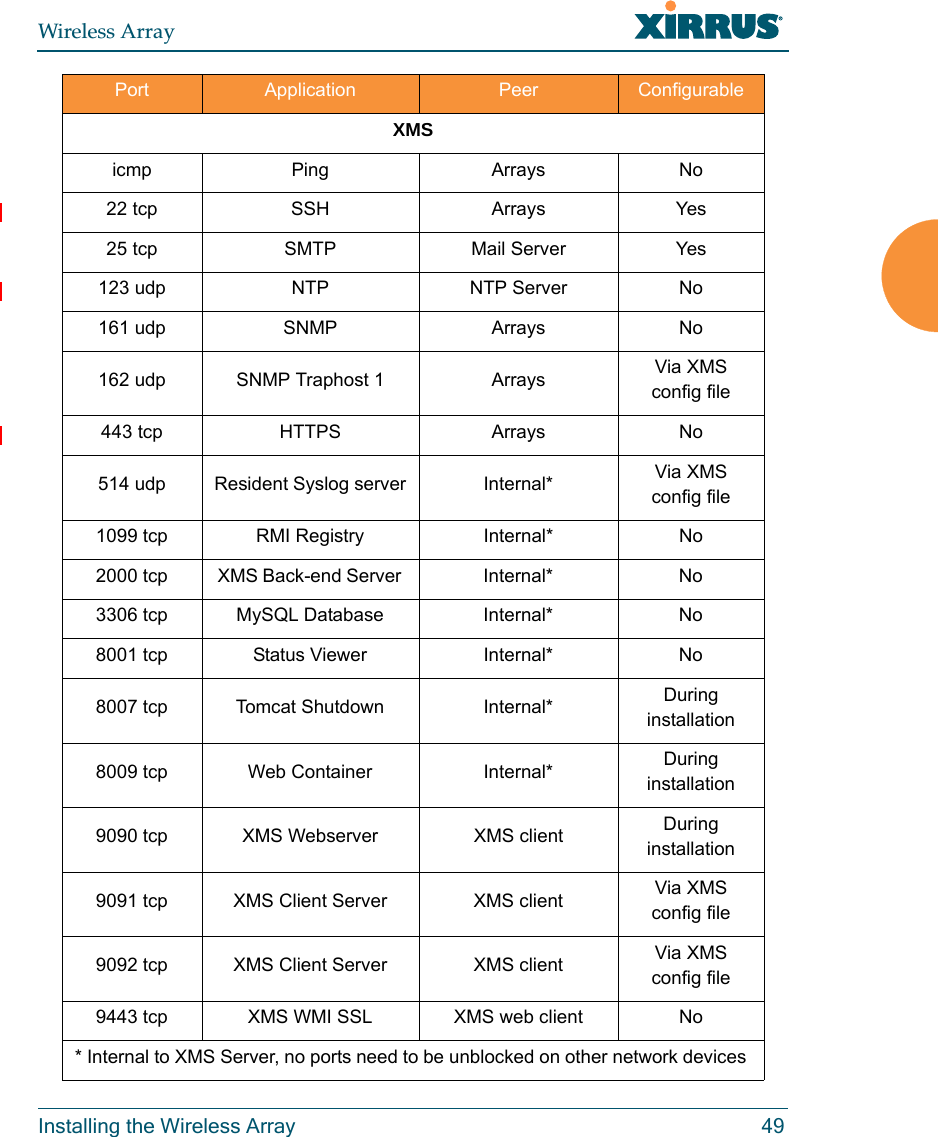
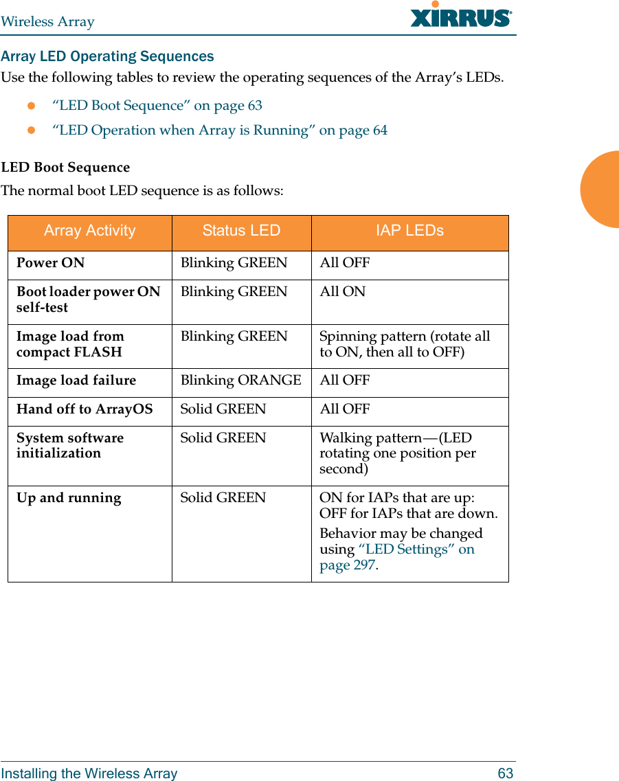
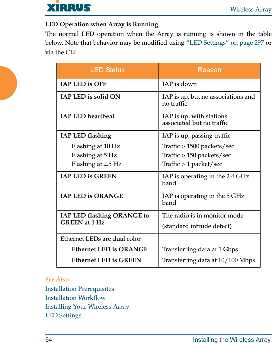
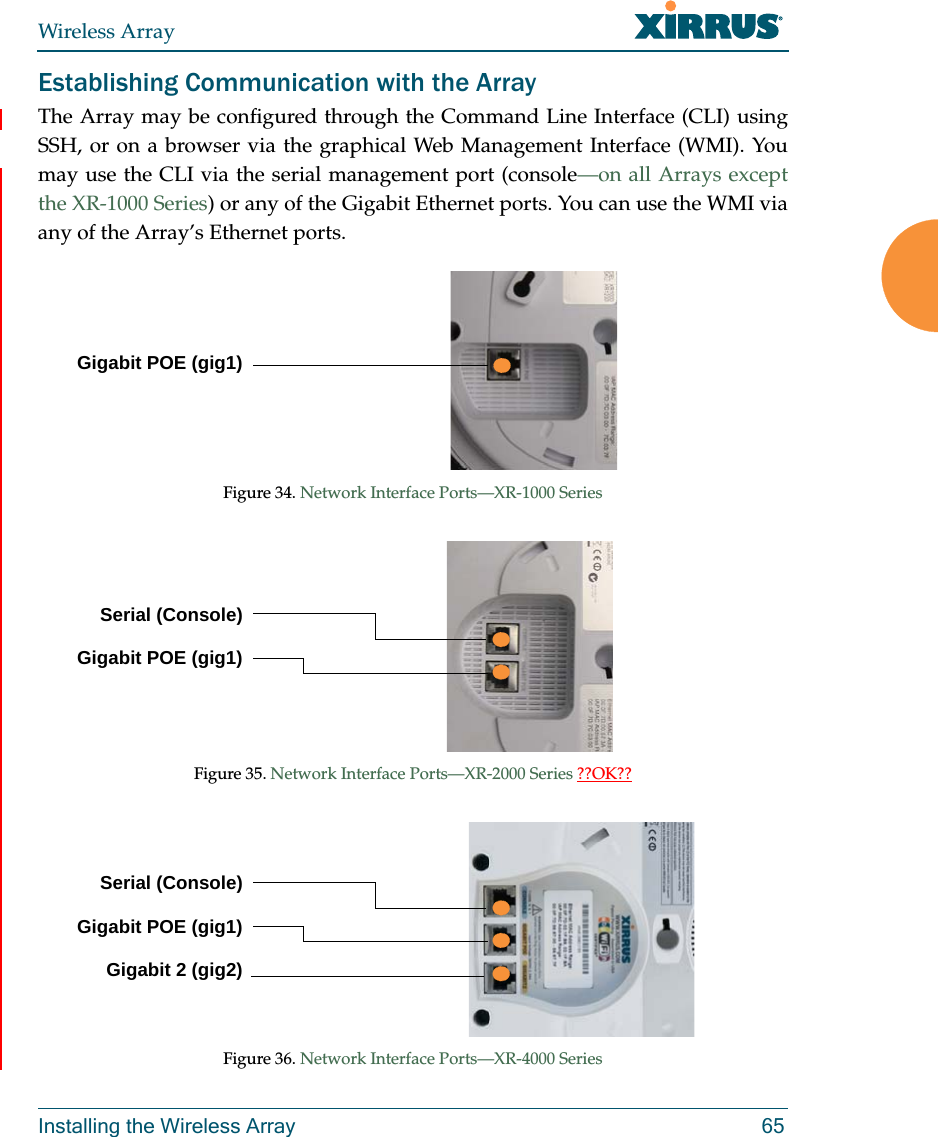
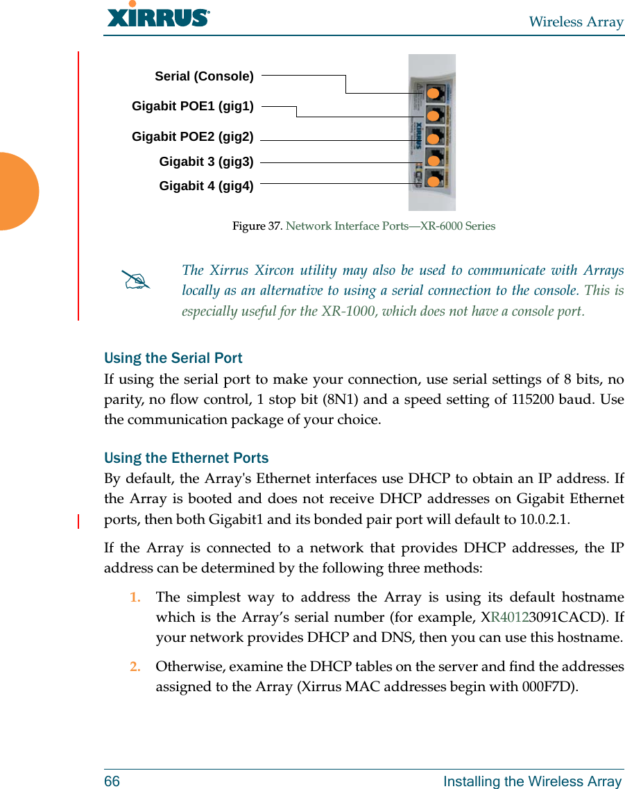
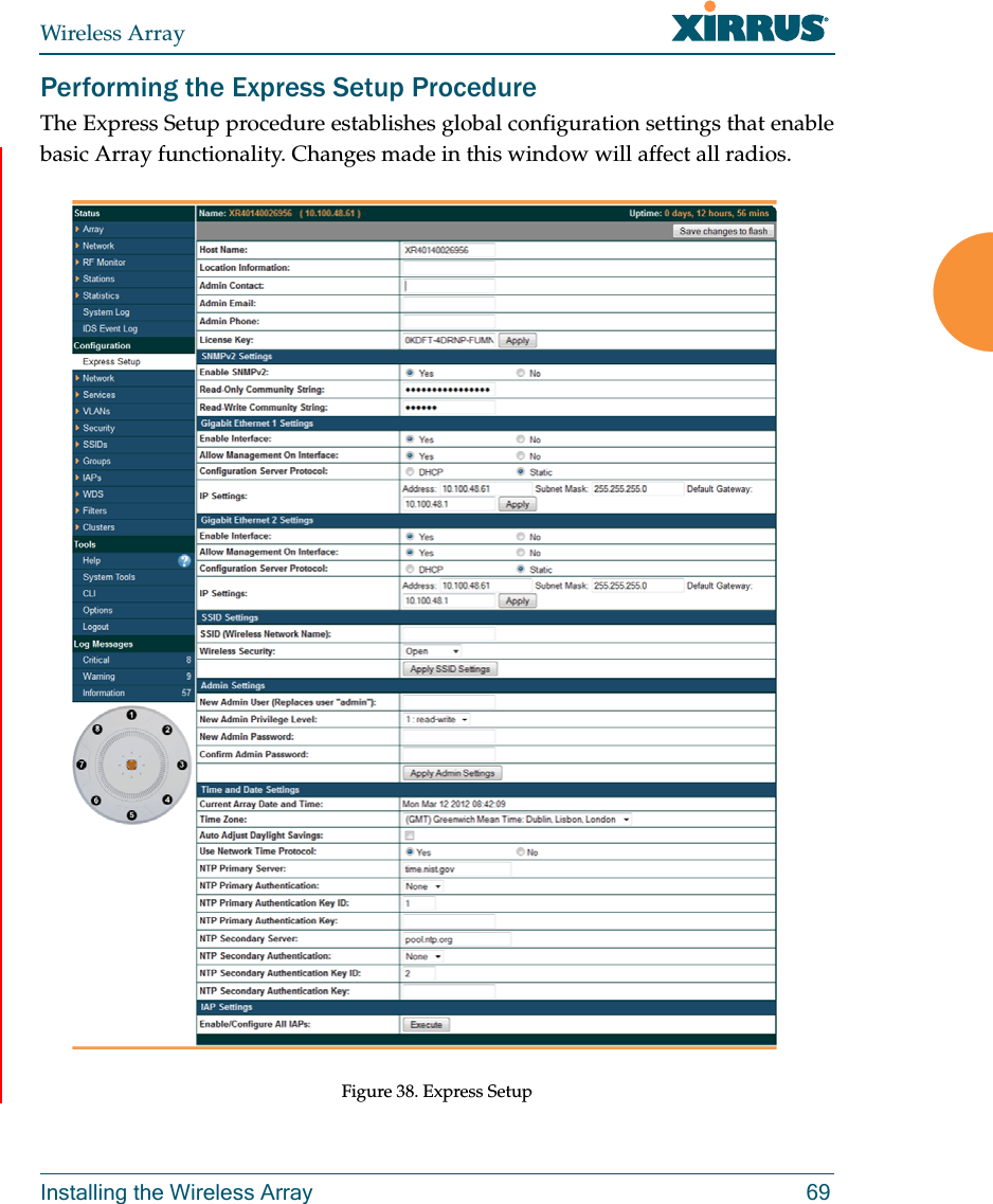
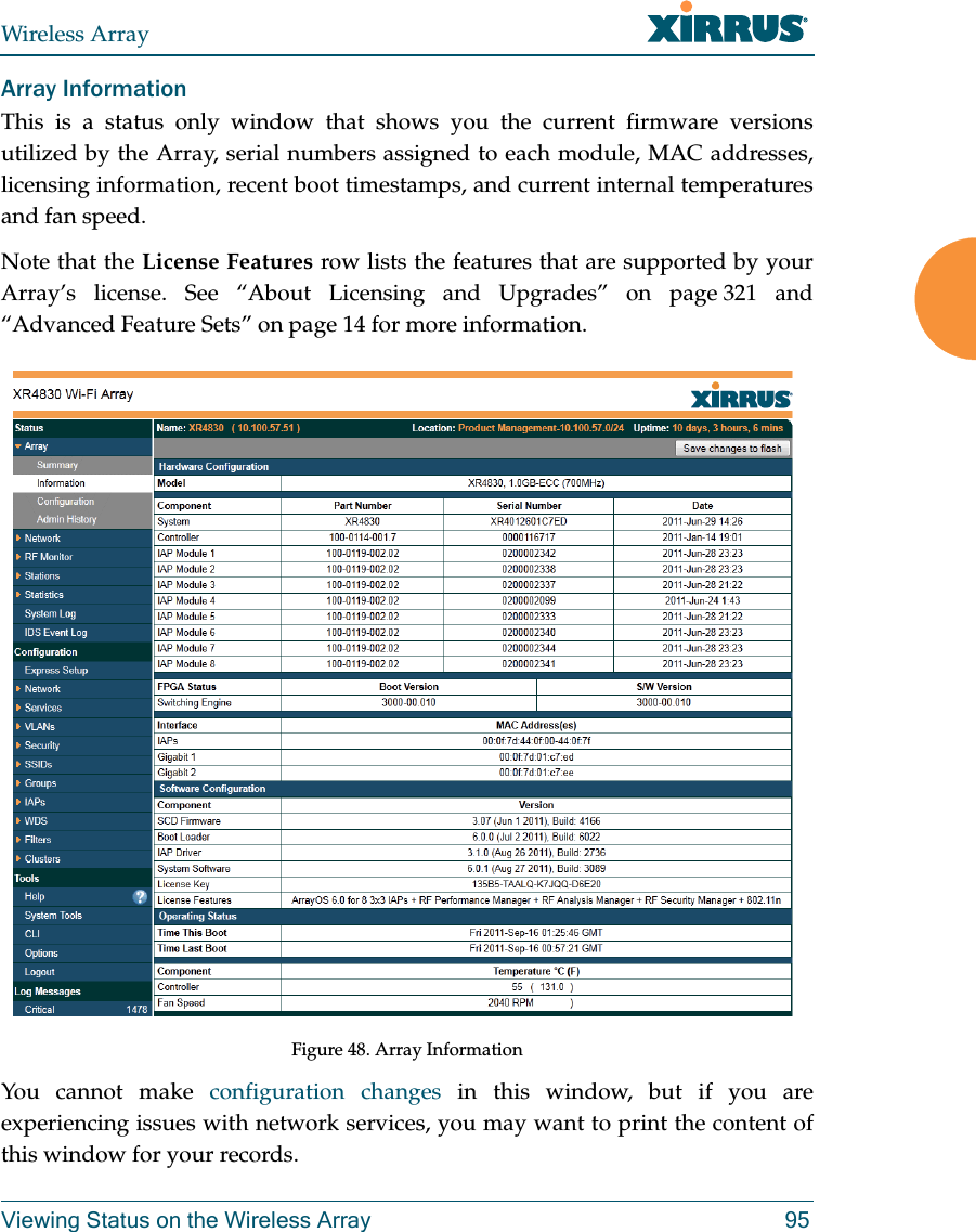
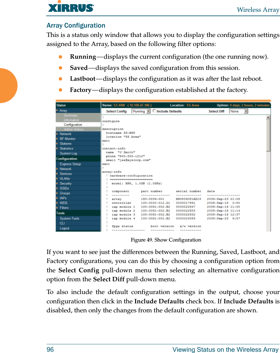
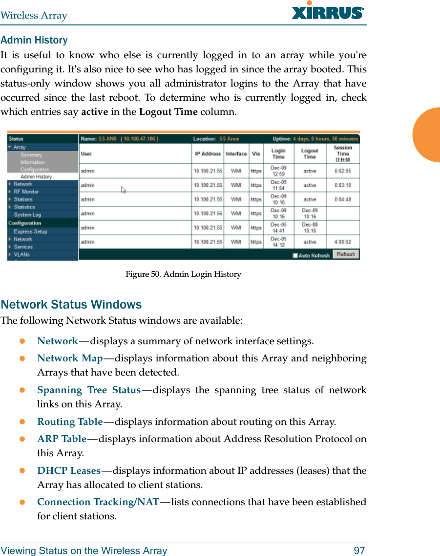
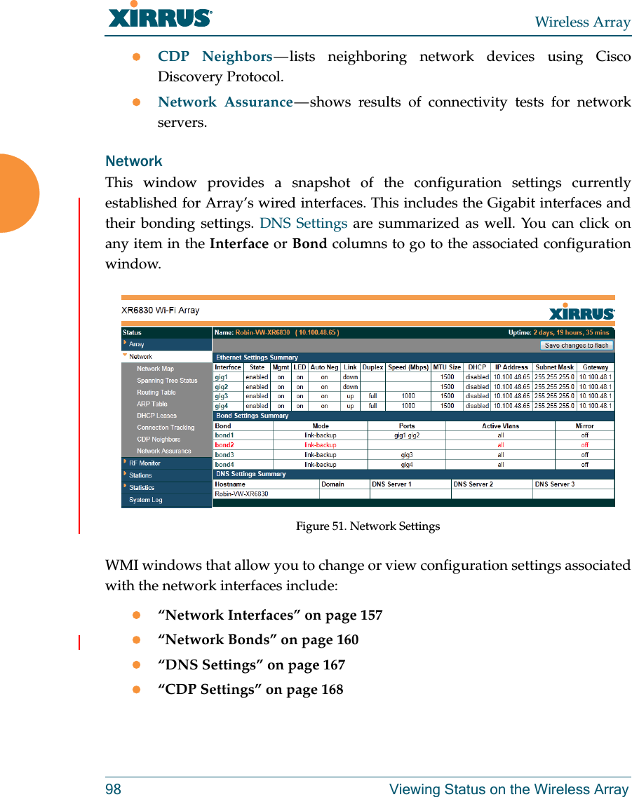
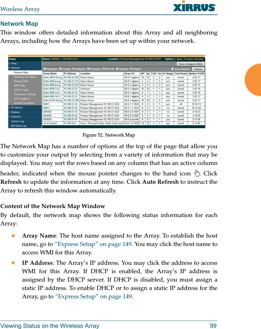
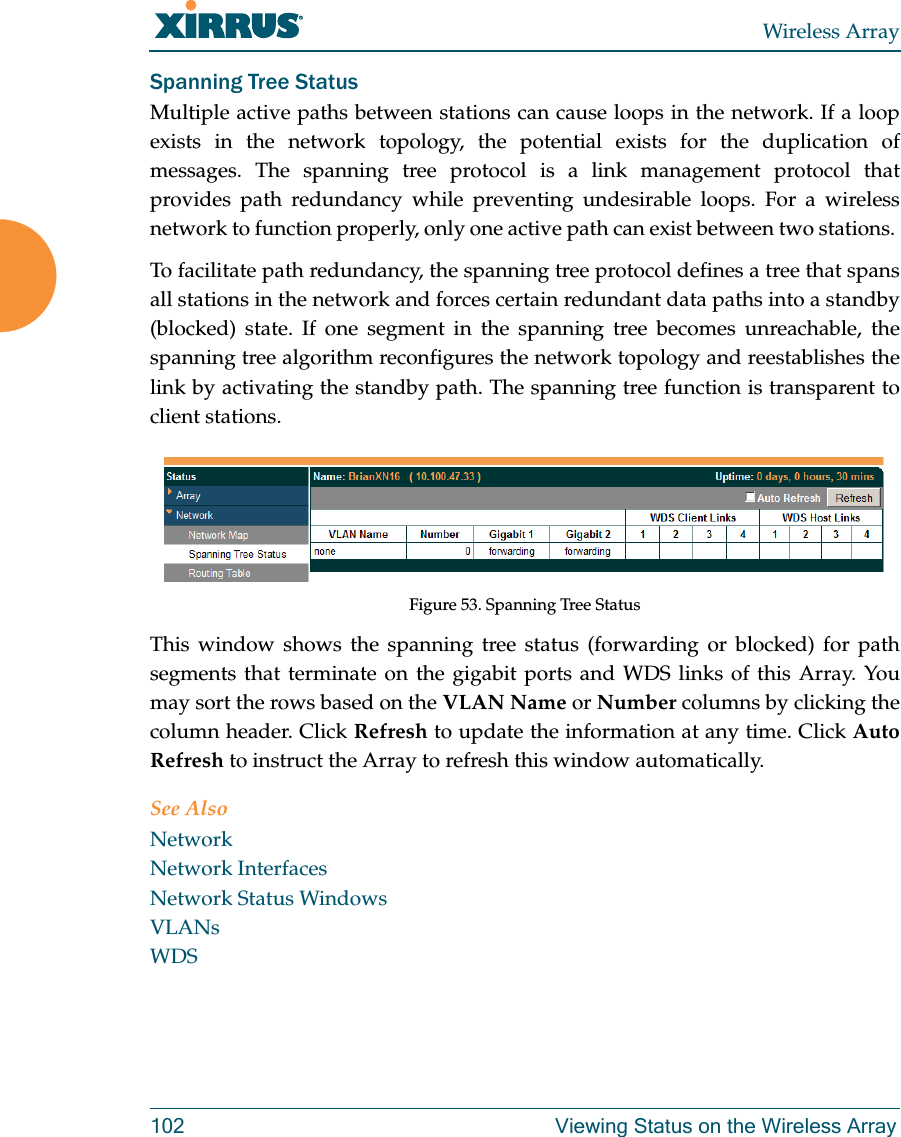
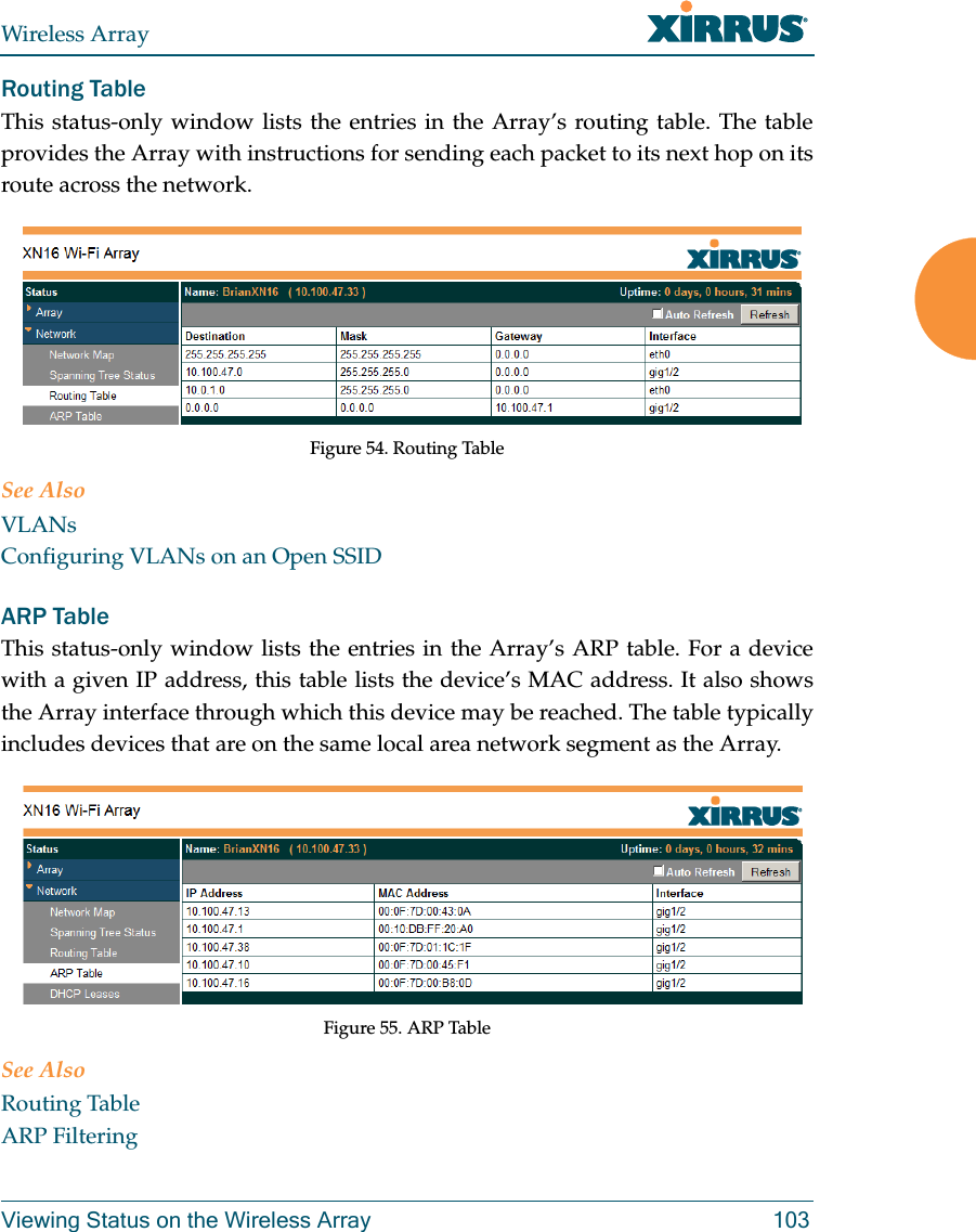
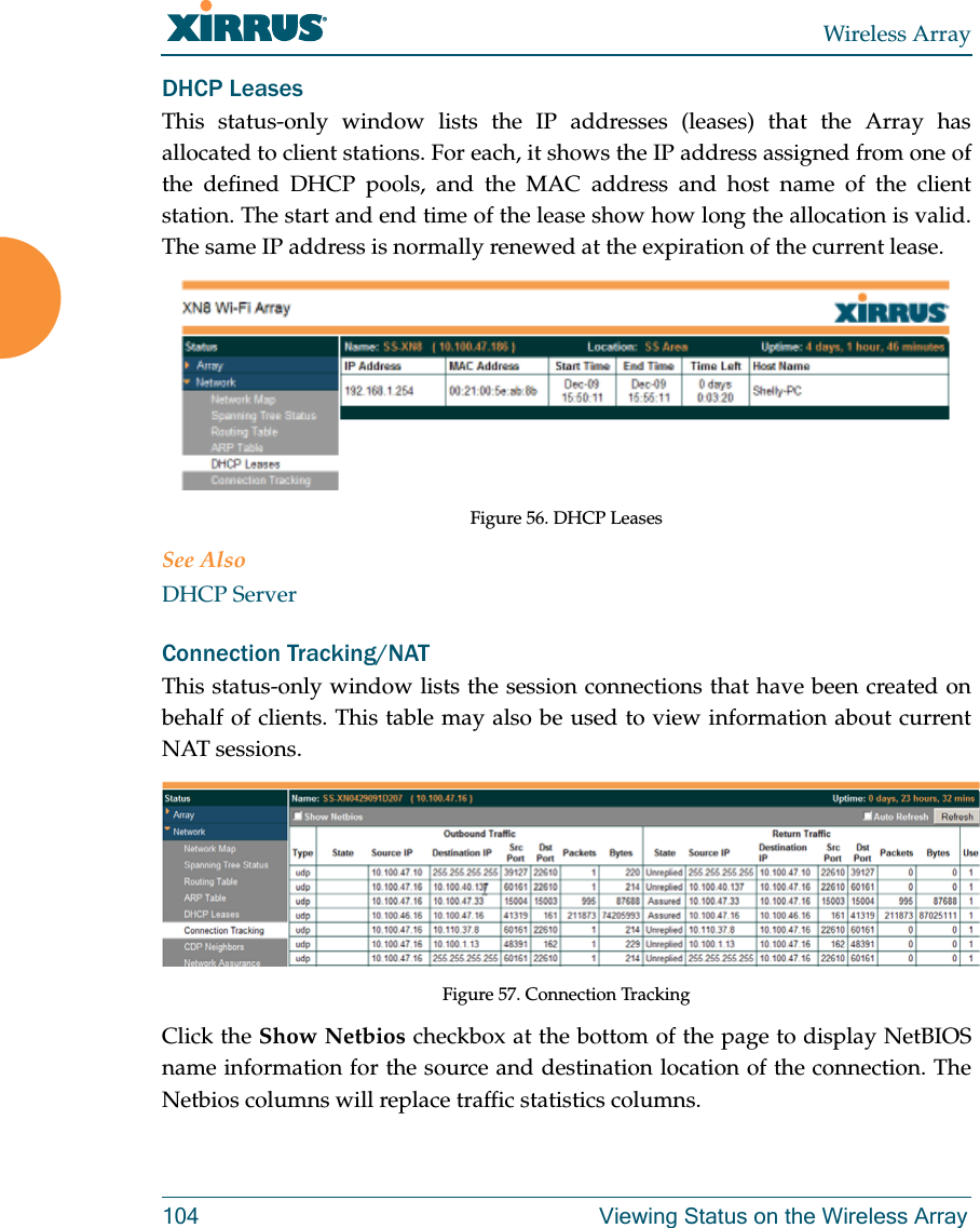
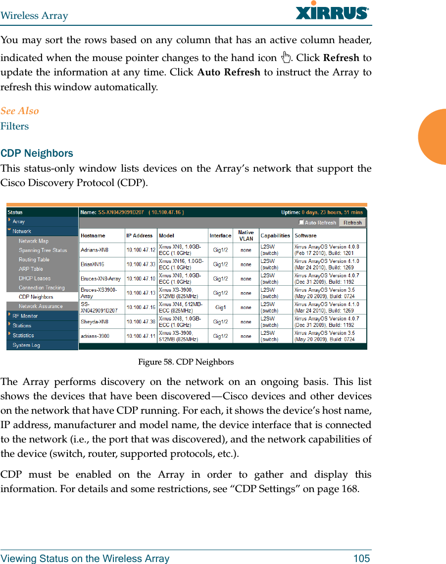
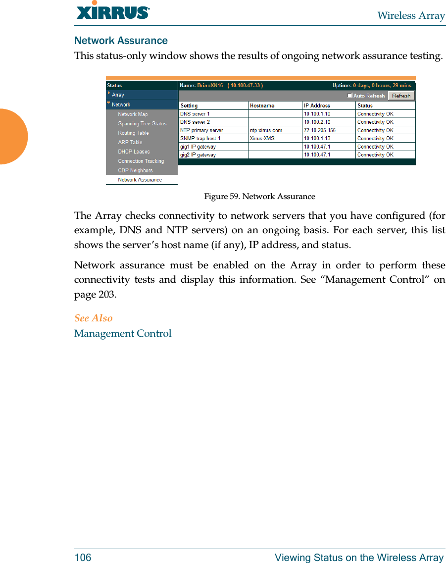
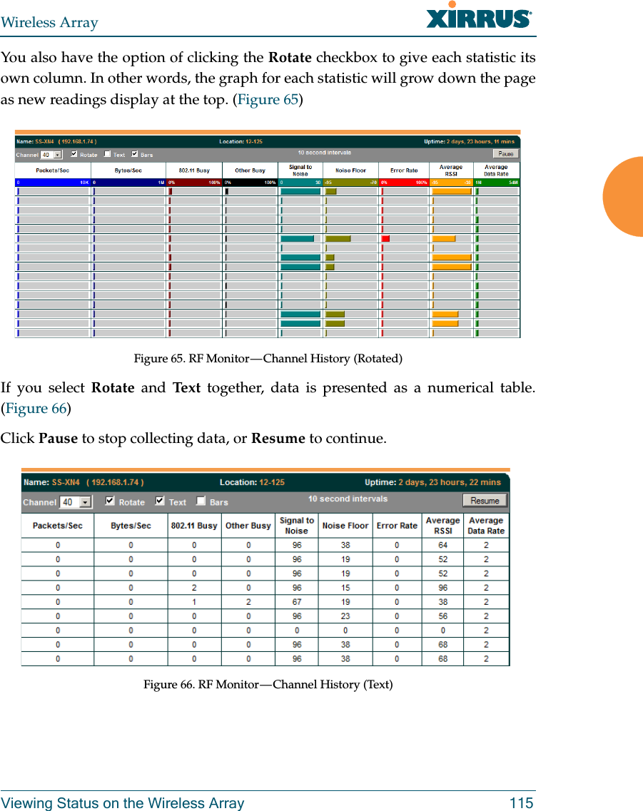
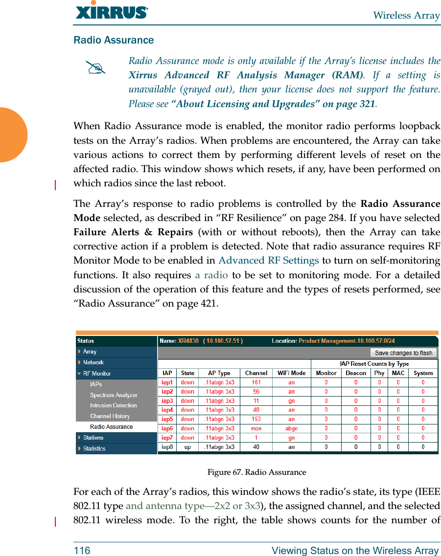
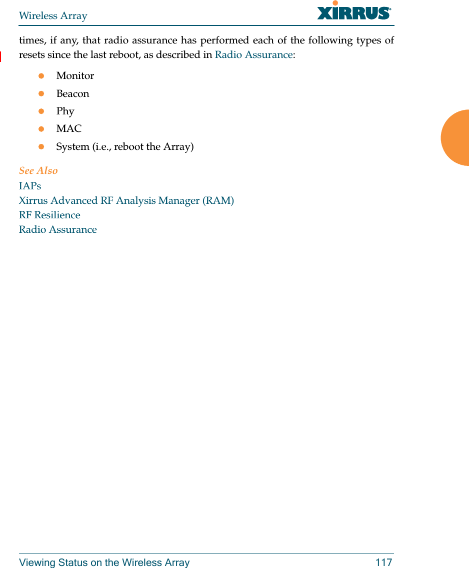
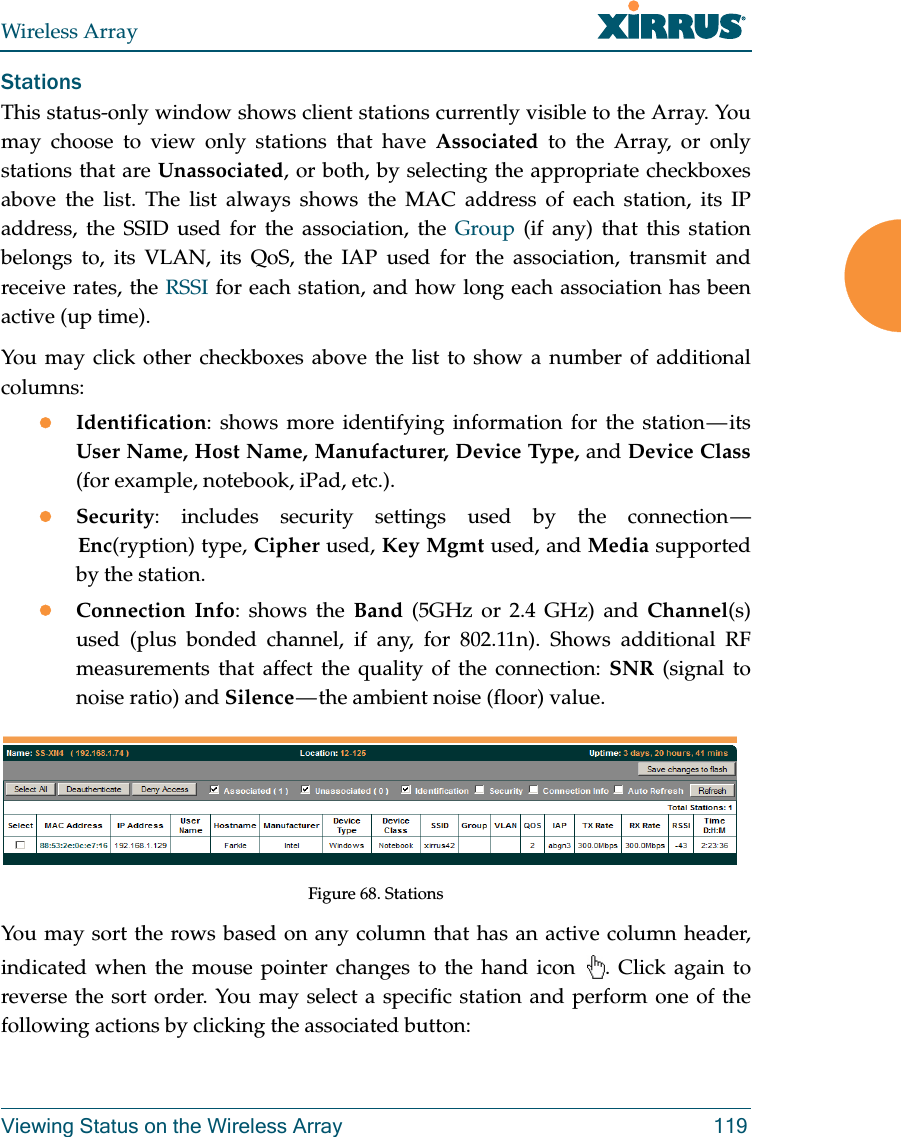
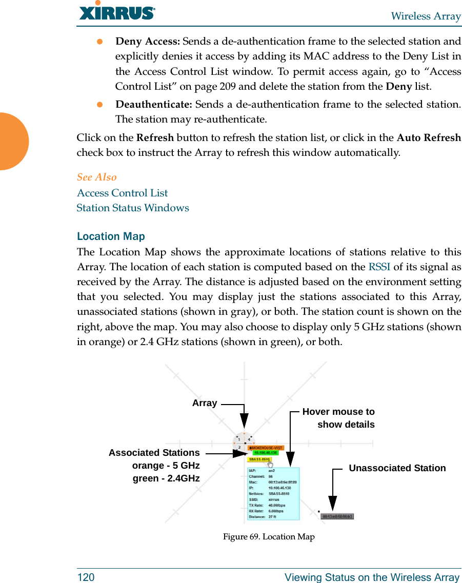
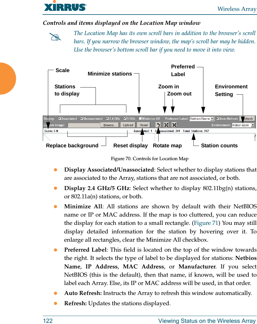
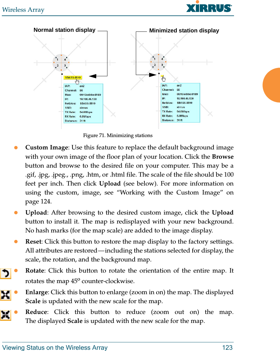
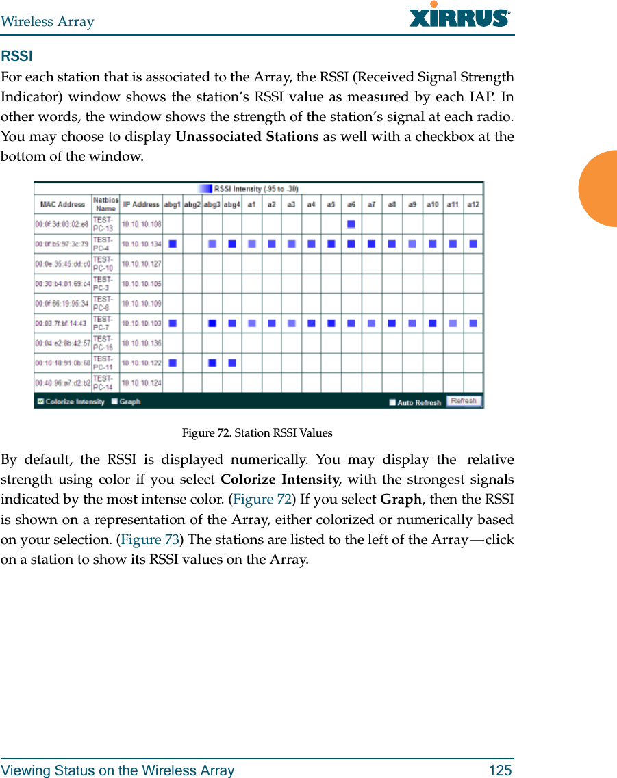
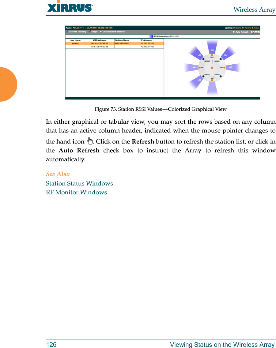
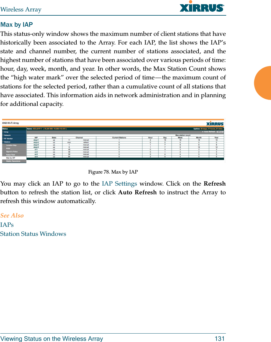
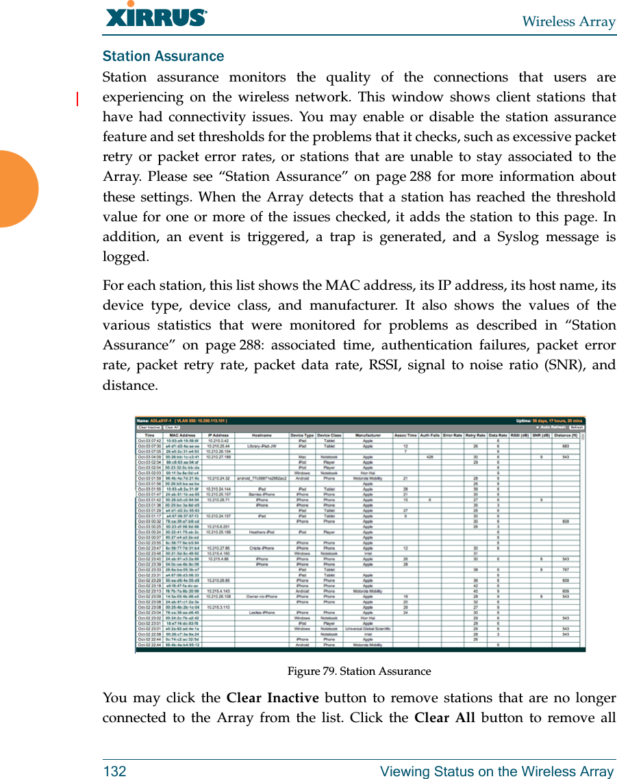
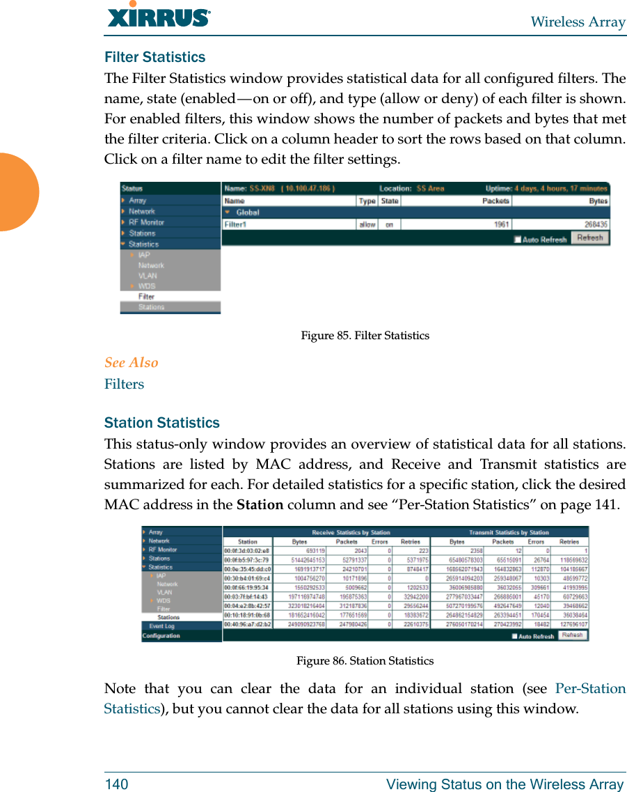
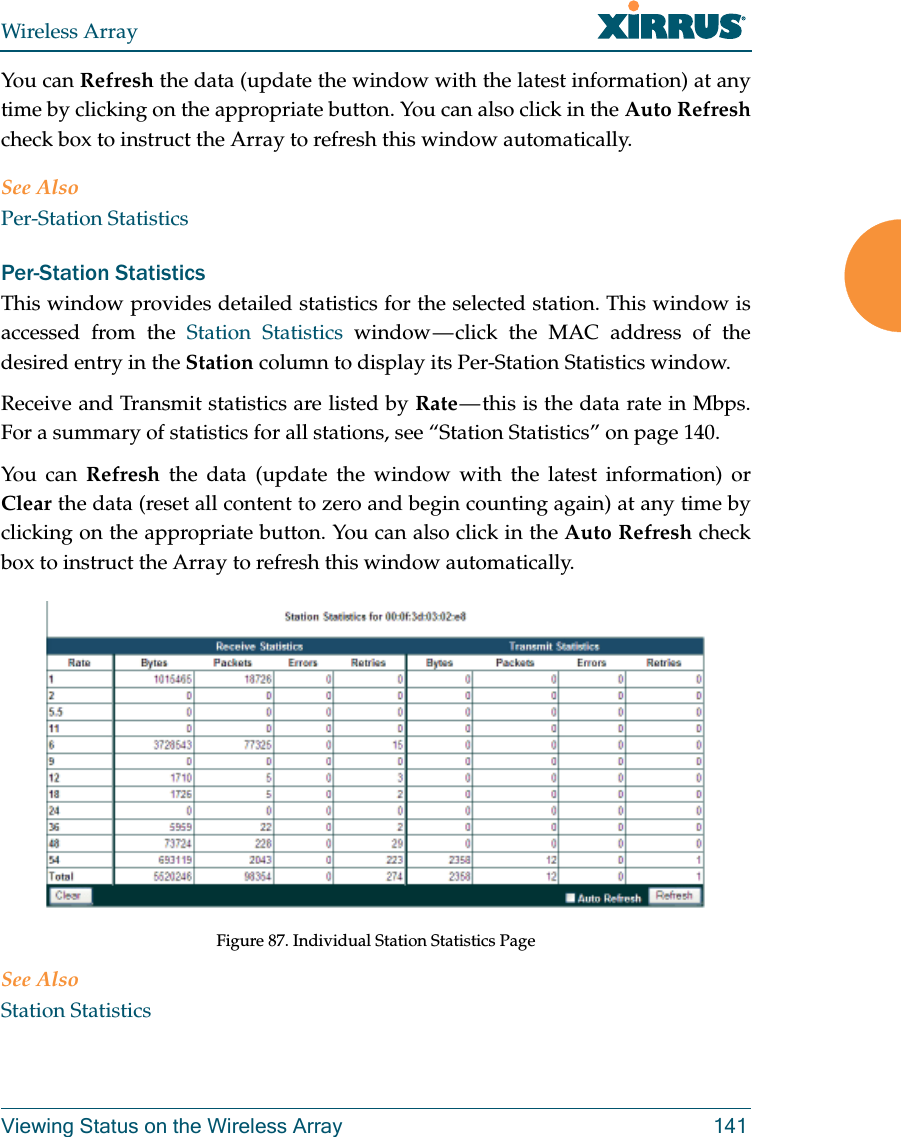
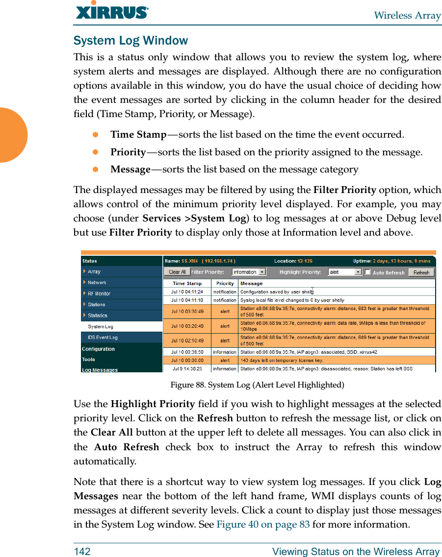
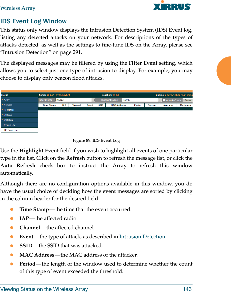
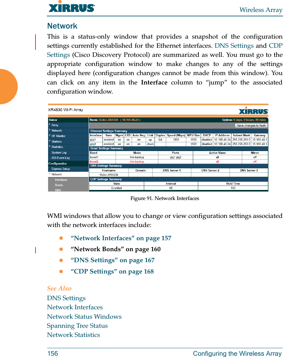
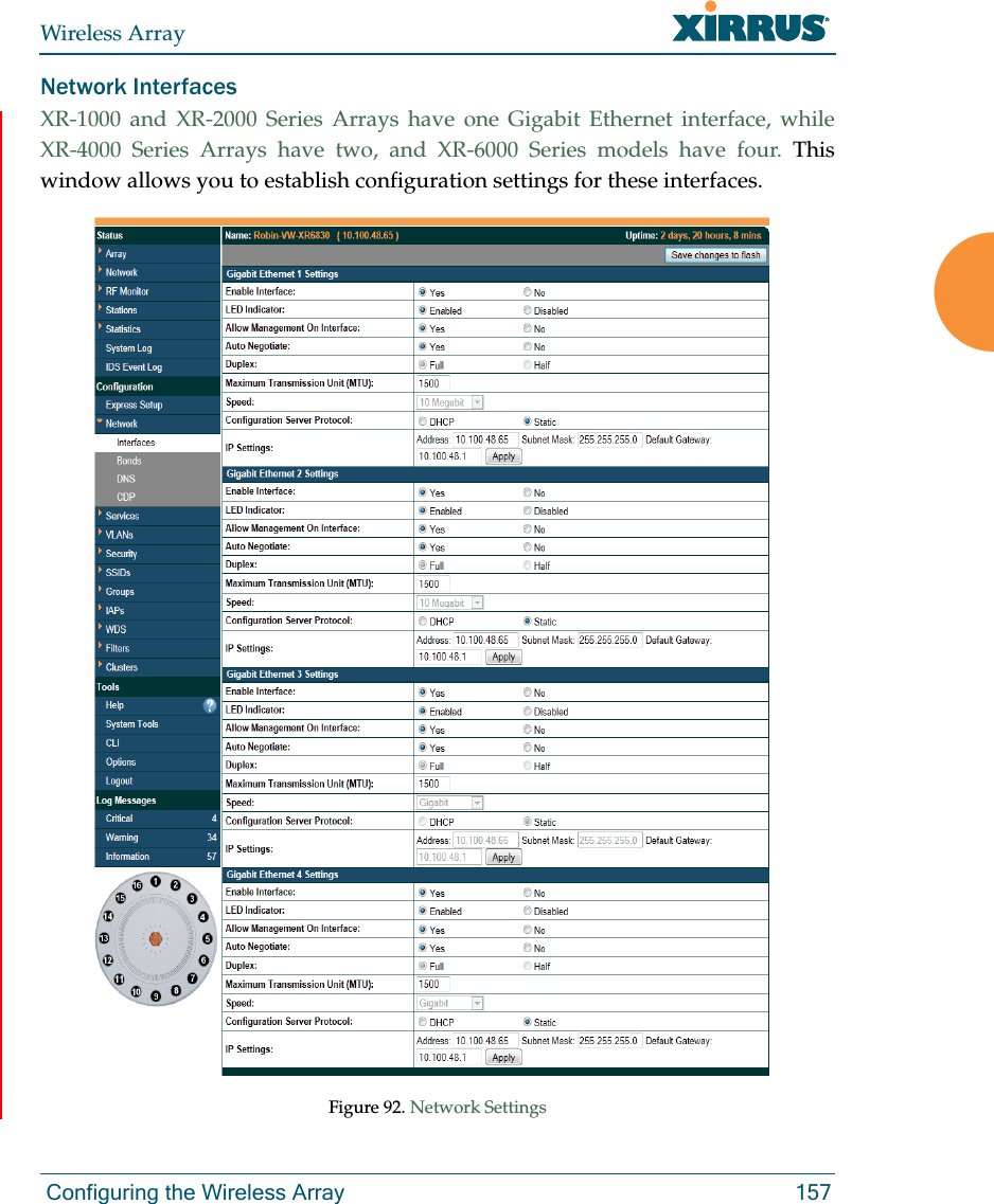
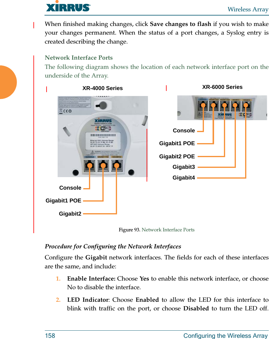
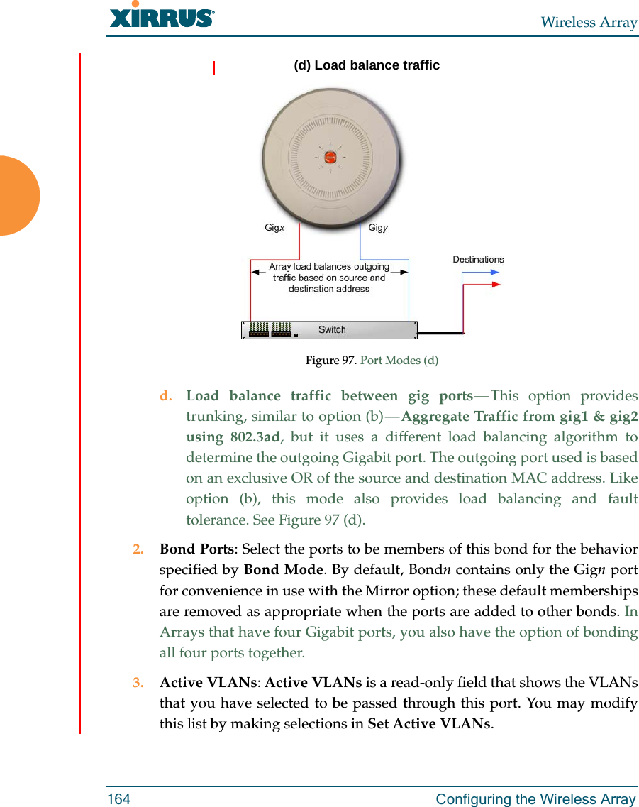
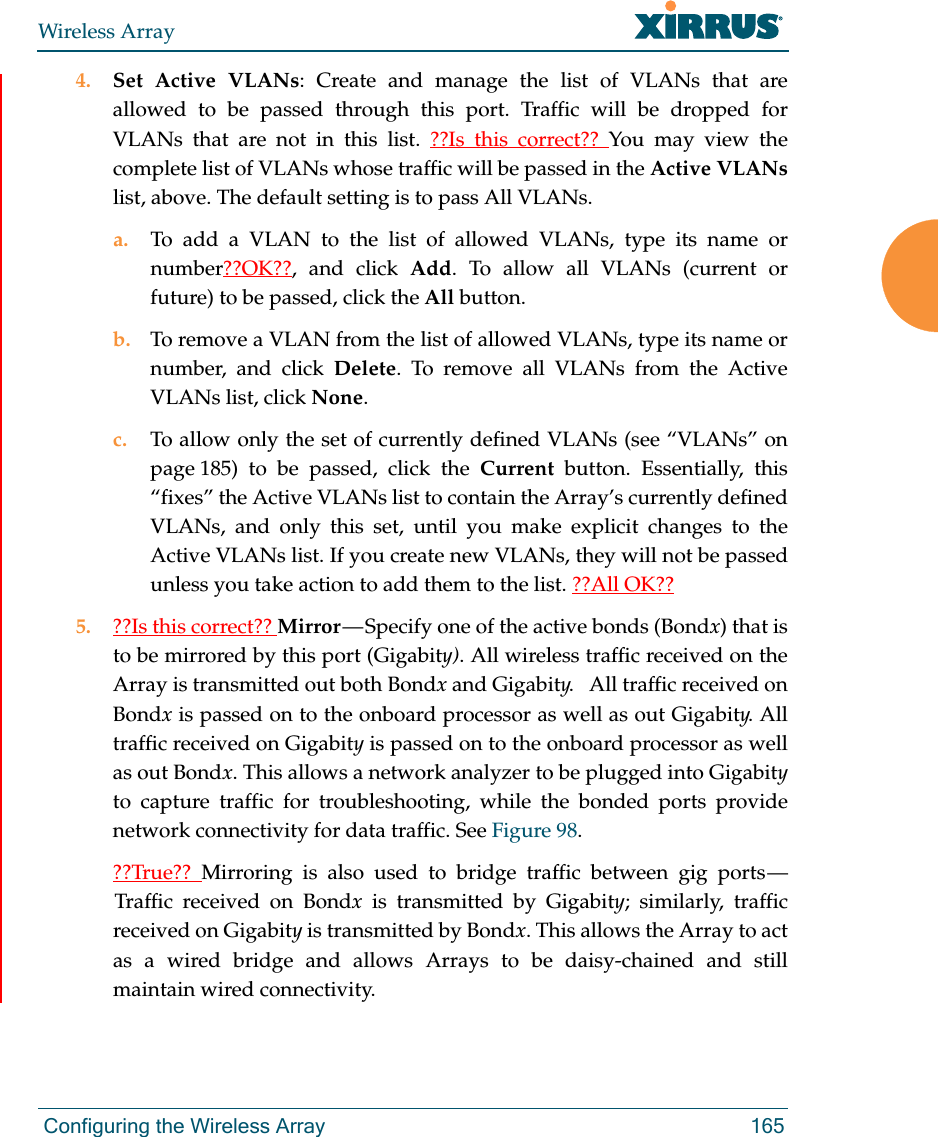
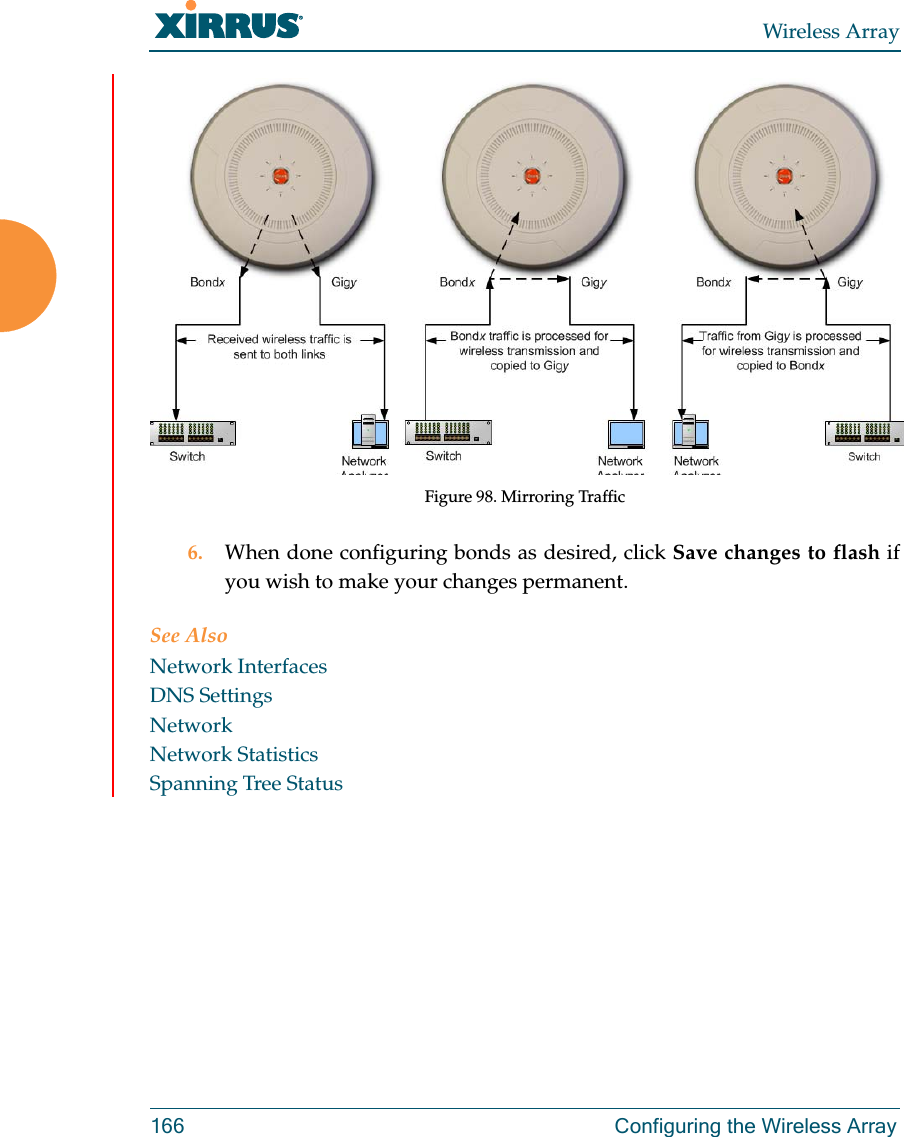
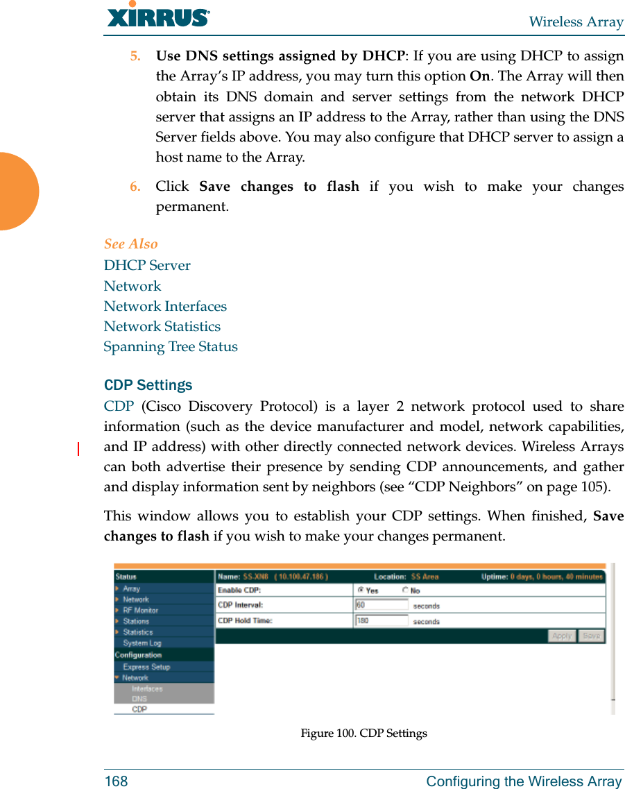
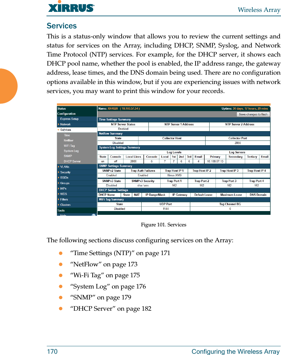
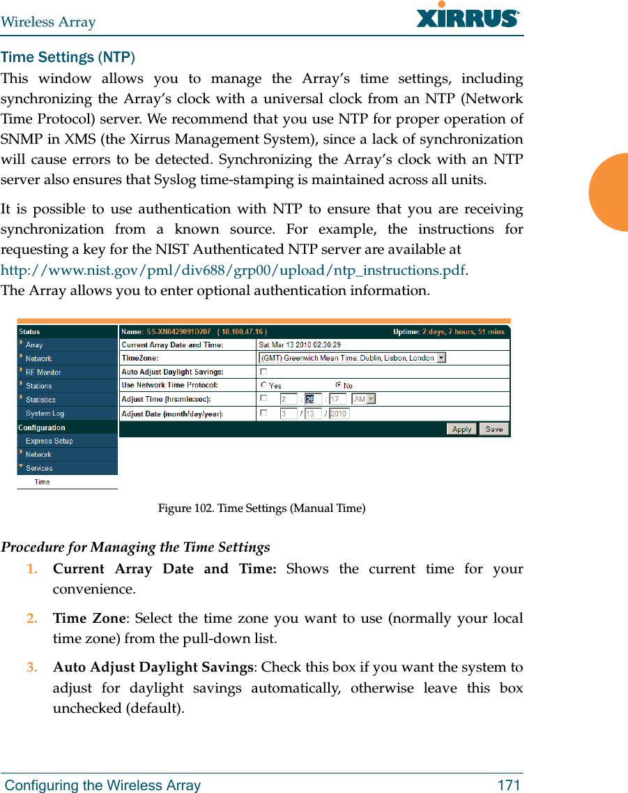
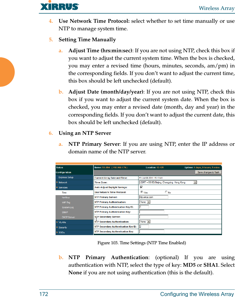
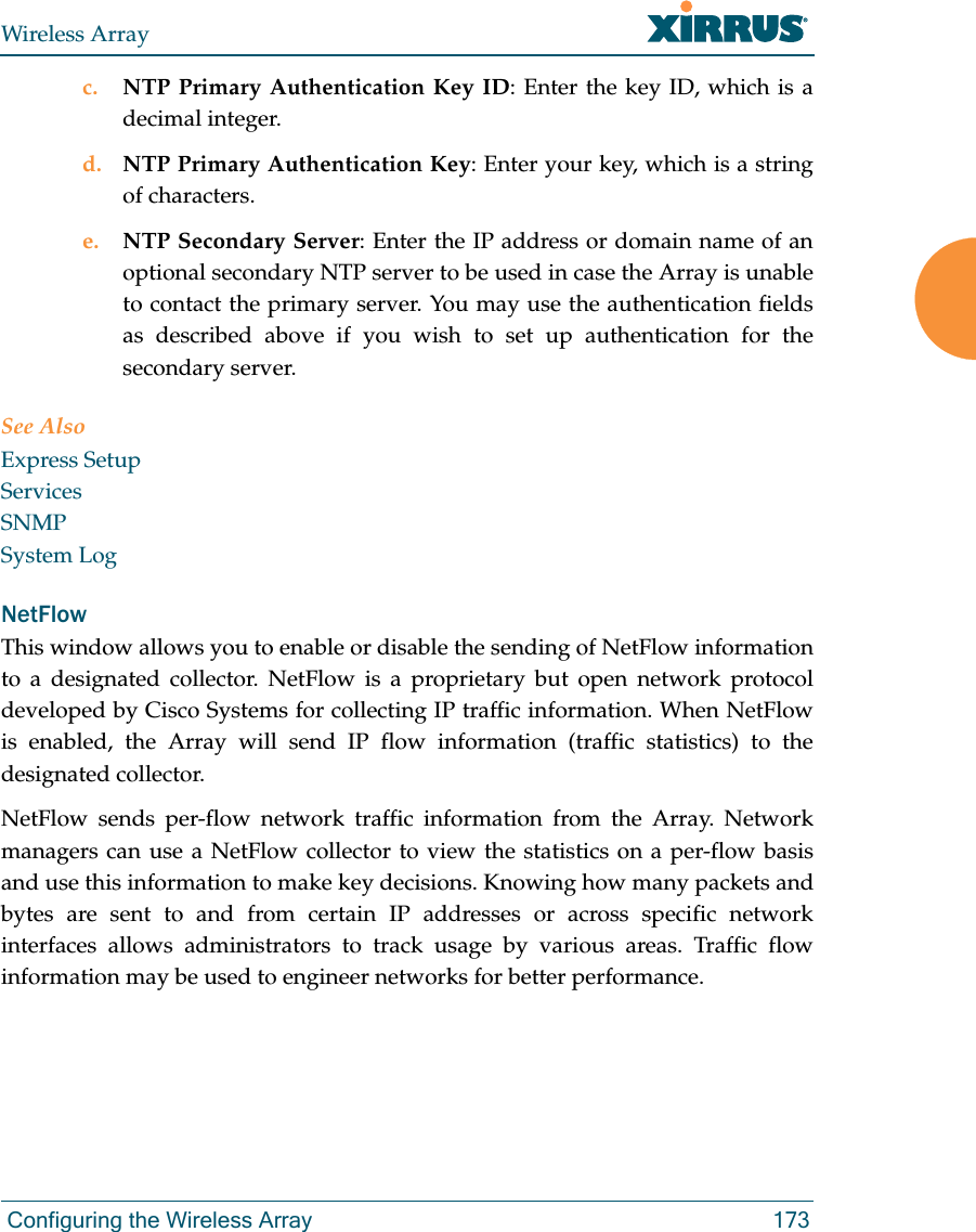
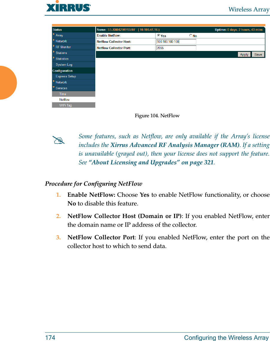
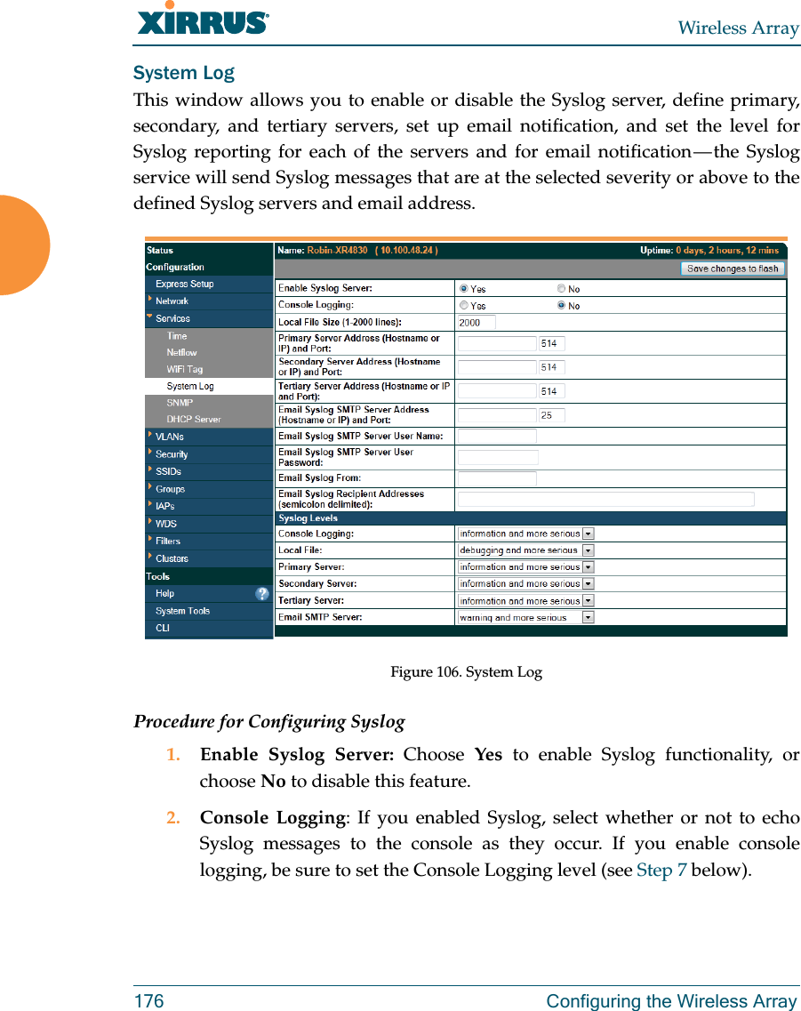
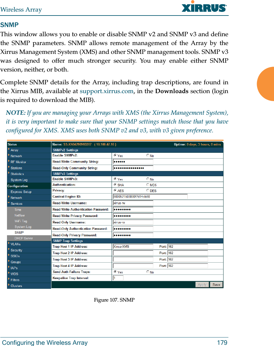
DRAFT5_ArrayGuide_XR_Rel6.1_RevD_Commentable-(1 of 2)

USER’S GUIDEHigh Performance Wireless NetworksWireless ArraysXR Series May 5, 2012 Release 6.1DRAFT5
All rights reserved. This document may not be reproduced or disclosed in whole or in part by any means without the written consent of Xirrus, Inc.Part Number: 800-0022-001(Revision D) Wireless Array™XR Series
Trademarksis a registered trademark of Xirrus, Inc. All other trademarks and brand names are marks of their respective holders.Please see Legal Notices, Warnings, Compliance Statements, and Warranty and License Agreements in “Appendix C: Notices” on page 431.Xirrus, Inc.2101 Corporate Center DriveThousand Oaks, CA 91320USATel: 1.805.262.16001.800.947.7871 Toll Free in the USFax: 1.866.462.3980www.xirrus.com
Wireless ArrayiTable of ContentsList of Figures...................................................................................... xiIntroduction .........................................................................................  1The Xirrus Family of Products ............................................................................... 1Nomenclature .................................................................................................... 3Why Choose the Xirrus Wireless Array? .............................................................. 3Wireless Array Product Overview ........................................................................ 5XR Wireless Array Product Family ................................................................ 6XR-1000 and XR-2000 Series Arrays  ....................................................... 6XR-4000 Series Arrays ............................................................................... 7XR-6000 Series Arrays ............................................................................... 8Enterprise Class Security ................................................................................. 9Deployment Flexibility  .................................................................................... 9Power over Gigabit Ethernet (PoGE) .................................................... 10Enterprise Class Management  ...................................................................... 10Key Features and Benefits ..................................................................................... 12High Capacity and High Performance ........................................................ 12Extended Coverage ......................................................................................... 12Non-Overlapping Channels .......................................................................... 13SDMA Optimization  ...................................................................................... 13Fast Roaming ................................................................................................... 13Easy Deployment ............................................................................................ 13Secure Wireless Access  .................................................................................. 13Applications Enablement  .............................................................................. 14Advanced Feature Sets .......................................................................................... 14Xirrus Advanced RF Performance Manager (RPM)  .................................. 14Xirrus Advanced RF Security Manager (RSM)  .......................................... 15Xirrus Advanced RF Analysis Manager (RAM) ......................................... 16About this User’s Guide ........................................................................................ 17Organization .................................................................................................... 17Notes and Cautions ........................................................................................ 19Screen Images .................................................................................................. 19Your User’s Guide as a PDF Document  ...................................................... 19
Wireless ArrayiiHyperlinks ....................................................................................................... 19Product Specifications — XR Array Family  ........................................................ 20Installing the Wireless Array........................................................... 21Installation Prerequisites  ...................................................................................... 21Optional Network Components ................................................................... 23Client Requirements ....................................................................................... 23Planning Your Installation .................................................................................... 24General Deployment Considerations  .......................................................... 24Coverage and Capacity Planning ................................................................. 26Placement .................................................................................................. 26RF Patterns ................................................................................................ 27Capacity and Cell Sizes ........................................................................... 28Fine Tuning Cell Sizes ............................................................................. 29Roaming Considerations  ........................................................................ 30Allocating Channels ................................................................................ 30Deployment Examples ............................................................................ 33IEEE 802.11n Deployment Considerations  ................................................. 35MIMO (Multiple-In Multiple-Out) ........................................................ 36Multiple Data Streams — Spatial Multiplexing  ................................... 37Channel Bonding ..................................................................................... 38Improved MAC Throughput ................................................................. 39Short Guard Interval  ............................................................................... 39Obtaining Higher Data Rates ................................................................. 40802.11n Capacity ...................................................................................... 41Failover Planning ............................................................................................ 41Switch Failover Protection  ..................................................................... 43Power Planning ............................................................................................... 44Power over Gigabit Ethernet  ................................................................. 44Security Planning ............................................................................................ 45Wireless Encryption  ................................................................................ 45Authentication ......................................................................................... 45Port Requirements  .......................................................................................... 47Network Management Planning  .................................................................. 51WDS Planning  ................................................................................................. 52Common Deployment Options  .................................................................... 55Installation Workflow  ........................................................................................... 56
Wireless ArrayiiiInstalling Your Wireless Array  ............................................................................ 58Choosing a Location ....................................................................................... 58Wiring Considerations ............................................................................ 58Mounting the Array  ....................................................................................... 61Dismounting the Array .................................................................................. 61Powering Up the Wireless Array ......................................................................... 62Array LED Operating Sequences  ................................................................. 63LED Boot Sequence  ................................................................................. 63LED Operation when Array is Running  .............................................. 64Establishing Communication with the Array .................................................... 65Using the Serial Port ....................................................................................... 66Using the Ethernet Ports ................................................................................ 66Starting the WMI ............................................................................................. 67Logging In ........................................................................................................ 67Entering the License  .............................................................................................. 67Performing the Express Setup Procedure ........................................................... 69Procedure for Performing an Express Setup  .............................................. 70Securing Low Level Access to the Array ..................................................... 76The Web Management Interface ................................................... 79An Overview  .......................................................................................................... 80Structure of the WMI ............................................................................................. 81User Interface  ......................................................................................................... 83Utility Buttons .......................................................................................... 85Logging In ............................................................................................................... 87Applying Configuration Changes ....................................................................... 87Character Restrictions  .................................................................................... 88Viewing Status on the Wireless Array ........................................... 89Array Status Windows .......................................................................................... 90Array Summary  .............................................................................................. 90Content of the Array Summary Window ............................................ 91Array Information  .......................................................................................... 95Array Configuration ....................................................................................... 96Admin History  ................................................................................................ 97Network Status Windows ..................................................................................... 97Network ........................................................................................................... 98
Wireless ArrayivNetwork Map  .................................................................................................. 99Content of the Network Map Window  ................................................ 99Spanning Tree Status .................................................................................... 102Routing Table  ................................................................................................ 103ARP Table  ...................................................................................................... 103DHCP Leases ................................................................................................. 104Connection Tracking/NAT ......................................................................... 104CDP Neighbors  ............................................................................................. 105Network Assurance ...................................................................................... 106RF Monitor Windows .......................................................................................... 107IAPs ................................................................................................................. 108Spectrum Analyzer  ...................................................................................... 109Intrusion Detection  ...................................................................................... 112Channel History ............................................................................................ 114Radio Assurance  ........................................................................................... 116Station Status Windows  ...................................................................................... 118Stations ........................................................................................................... 119Location Map ................................................................................................. 120RSSI ................................................................................................................. 125Signal-to-Noise Ratio (SNR) ........................................................................ 127Noise Floor ..................................................................................................... 129Max by IAP  .................................................................................................... 131Station Assurance  ......................................................................................... 132Statistics Windows ............................................................................................... 134IAP Statistics Summary ................................................................................ 134Per-IAP Statistics ........................................................................................... 135Network Statistics ......................................................................................... 137VLAN Statistics ............................................................................................. 138WDS Statistics ................................................................................................ 139Filter Statistics  ............................................................................................... 140Station Statistics  ............................................................................................ 140Per-Station Statistics  ..................................................................................... 141System Log Window  ........................................................................................... 142IDS Event Log Window  ...................................................................................... 143 Configuring the Wireless Array...................................................  147Express Setup ........................................................................................................ 149
Wireless ArrayvNetwork ................................................................................................................. 156Network Interfaces   ...................................................................................... 157Network Interface Ports ........................................................................ 158Network Bonds  ............................................................................................. 160DNS Settings .................................................................................................. 167CDP Settings .................................................................................................. 168Services .................................................................................................................. 170Time Settings (NTP)  ..................................................................................... 171NetFlow .......................................................................................................... 173Wi-Fi Tag  ....................................................................................................... 175System Log ..................................................................................................... 176SNMP .............................................................................................................. 179DHCP Server  ................................................................................................. 182VLANs ................................................................................................................... 185Understanding Virtual Tunnels  .......................................................... 185VLAN Management  ..................................................................................... 187Security .................................................................................................................. 190Understanding Security ........................................................................ 191Certificates and Connecting Securely to the WMI ............................ 194Using the Array’s Default Certificate  ................................................. 194Using an External Certificate Authority ............................................. 195Admin Management  .................................................................................... 196Admin Privileges  .......................................................................................... 198Admin RADIUS  ............................................................................................ 200About Creating Admin Accounts on the RADIUS Server   ............. 200Management Control  ................................................................................... 203Access Control List ....................................................................................... 209Global Settings  .............................................................................................. 212External Radius ............................................................................................. 216About Creating User Accounts on the RADIUS Server  .................. 216Internal Radius .............................................................................................. 219Rogue Control List ........................................................................................ 222SSIDs ...................................................................................................................... 224Understanding SSIDs ............................................................................ 225Understanding QoS Priority on the Wireless Array  ........................ 226SSID Management  ........................................................................................ 231SSID List (top of page)  .......................................................................... 232
Wireless ArrayviSSID Limits  ............................................................................................. 236Web Page Redirect Configuration Settings  ....................................... 237WPA Configuration Settings   .............................................................. 241RADIUS Configuration Settings  ......................................................... 242Active IAPs  .................................................................................................... 243Per-SSID Access Control List  ...................................................................... 244Groups ................................................................................................................... 246Understanding Groups ......................................................................... 246Using Groups  ......................................................................................... 247Group Management  ..................................................................................... 248Group Limits  .......................................................................................... 250IAPs ........................................................................................................................ 253Understanding Fast Roaming .............................................................. 255IAP Settings  ................................................................................................... 256Global Settings (IAP)  ................................................................................... 261Beacon Configuration  ........................................................................... 263Station Management  ............................................................................. 263Advanced Traffic Optimization  .......................................................... 264Global Settings .11an  .................................................................................... 270Global Settings .11bgn .................................................................................. 274Global Settings .11n  ...................................................................................... 279Advanced RF Settings .................................................................................. 282About Standby Mode ............................................................................ 282RF Monitor .............................................................................................. 283RF Resilience  .......................................................................................... 284RF Power & Sensitivity ......................................................................... 285RF Spectrum Management ................................................................... 287Station Assurance  .................................................................................. 288Intrusion Detection ....................................................................................... 291DoS Attacks  ............................................................................................ 292Impersonation Attacks .......................................................................... 293About Blocking Rogue APs .................................................................. 294RF Intrusion Detection and Auto Block Mode .................................. 294DoS Attack Detection Settings ............................................................. 295Impersonation Detection Settings ....................................................... 296LED Settings  .................................................................................................. 297DSCP Mappings ............................................................................................ 298
Wireless ArrayviiRoaming Assist .............................................................................................. 299WDS ....................................................................................................................... 302About Configuring WDS Links ........................................................... 302Long Distance Links .............................................................................. 303WDS Client Links .......................................................................................... 304Filters ..................................................................................................................... 308Filter Lists  ...................................................................................................... 309Filter Management  ....................................................................................... 311Clusters .................................................................................................................. 314Cluster Definition   ........................................................................................ 315Cluster Management  ................................................................................... 316Cluster Operation   ........................................................................................ 317Using Tools on the Wireless Array...............................................  319System Tools ......................................................................................................... 320About Licensing and Upgrades ........................................................... 321System ..................................................................................................... 322Automatic Updates from Remote Image or Configuration File  .... 323Configuration ......................................................................................... 324Diagnostics ............................................................................................. 326Web Page Redirect ................................................................................. 328Network Tools ........................................................................................ 329Progress and Status Frames  ................................................................. 331CLI  ......................................................................................................................... 332Options .................................................................................................................. 333Logout .................................................................................................................... 336The Command Line Interface ......................................................  337Establishing a Secure Shell (SSH) Connection ................................................. 337Getting Started with the CLI  .............................................................................. 339Inputting Commands ................................................................................... 339Getting Help  .................................................................................................. 339Top Level Commands  ......................................................................................... 341Root Command Prompt ............................................................................... 341configure Commands ................................................................................... 342show Commands  .......................................................................................... 345statistics Commands ..................................................................................... 348
Wireless ArrayviiiConfiguration Commands .................................................................................. 350acl .................................................................................................................... 350admin .............................................................................................................. 351cdp ................................................................................................................... 352clear ................................................................................................................. 353cluster ............................................................................................................. 354contact-info .................................................................................................... 355date-time ........................................................................................................ 356dhcp-server .................................................................................................... 357dns ................................................................................................................... 358file .................................................................................................................... 359filter ................................................................................................................. 362Air Cleaner  ............................................................................................. 363group .............................................................................................................. 366hostname ........................................................................................................ 366interface .......................................................................................................... 367load ................................................................................................................. 367location ........................................................................................................... 368management .................................................................................................. 368more ................................................................................................................ 370netflow ............................................................................................................ 371no ..................................................................................................................... 372quit .................................................................................................................. 374radius-server .................................................................................................. 374reboot .............................................................................................................. 375reset ................................................................................................................. 375restore ............................................................................................................. 376run-tests .......................................................................................................... 377security ........................................................................................................... 379snmp ............................................................................................................... 380ssid .................................................................................................................. 381syslog .............................................................................................................. 382uptime ............................................................................................................. 383vlan .................................................................................................................. 384wifi-tag ........................................................................................................... 385Sample Configuration Tasks  .............................................................................. 386Configuring a Simple Open Global SSID .................................................. 387
Wireless ArrayixConfiguring a Global SSID using WPA-PEAP ......................................... 388Configuring an SSID-Specific SSID using WPA-PEAP ........................... 389Enabling Global IAPs ................................................................................... 390Disabling Global IAPs .................................................................................. 391Enabling a Specific IAP ................................................................................ 392Disabling a Specific IAP ............................................................................... 393Setting Cell Size Auto-Configuration for All IAPs  .................................. 394Setting the Cell Size for All IAPs ................................................................ 395Setting the Cell Size for a Specific IAP ....................................................... 396Configuring VLANs on an Open SSID ...................................................... 397Configuring Radio Assurance Mode (Loopback Tests) .......................... 398Appendices.....................................................................................  401Appendix A: Quick Reference Guide  ............................................................... 403Factory Default Settings ...................................................................................... 403Host Name ..................................................................................................... 403Network Interfaces  ....................................................................................... 403Serial ........................................................................................................ 403Gigabit 1 and Gigabit 2 ......................................................................... 404Server Settings ............................................................................................... 404NTP .......................................................................................................... 404Syslog ...................................................................................................... 404SNMP ...................................................................................................... 405DHCP .............................................................................................................. 405Default SSID  .................................................................................................. 406Security  .......................................................................................................... 406Global Settings - Encryption   ............................................................... 406External RADIUS (Global)   .................................................................. 407Internal RADIUS .................................................................................... 408Administrator Account and Password ...................................................... 408Management .................................................................................................. 408Keyboard Shortcuts  ............................................................................................. 409Appendix B: Technical Support  ........................................................................ 411General Hints and Tips  ....................................................................................... 411Frequently Asked Questions .............................................................................. 412Multiple SSIDs ............................................................................................... 412
Wireless ArrayxSecurity ........................................................................................................... 414VLAN Support .............................................................................................. 417Array Monitor and Radio Assurance Capabilities .......................................... 420Enabling Monitoring on the Array  ..................................................... 420How Monitoring Works ............................................................................... 420Radio Assurance  ........................................................................................... 421Radio Assurance Options ..................................................................... 422RADIUS Vendor Specific Attribute (VSA) for Xirrus ..................................... 423Upgrading the Array via CLI ............................................................................. 424Sample Output for the Upgrade Procedure: ............................................. 425Contact Information  ............................................................................................ 429Appendix C: Notices  ........................................................................................... 431Notices ................................................................................................................... 431EU Directive 1999/5/EC Compliance Information ........................................ 435Compliance Information (Non-EU) ................................................................... 442Safety Warnings  ................................................................................................... 443Translated Safety Warnings  ............................................................................... 444Software License and Product Warranty Agreement ..................................... 445Hardware Warranty Agreement  ....................................................................... 451Glossary of Terms..........................................................................  453Index................................................................................................  465
Wireless ArrayList of Figures xiList of FiguresFigure 1. Xirrus Arrays: XR Series............................................................................ 1Figure 2. The Xirrus Management System .............................................................. 2Figure 3. Wireless Array (XR Series)........................................................................ 5Figure 4. Wireless Coverage Patterns ...................................................................... 9Figure 5. WMI: Array Status.................................................................................... 11Figure 6. Layout of IAPs (XR-7630) ........................................................................ 12Figure 7. Wall Thickness Considerations .............................................................. 25Figure 8. Unit Placement.......................................................................................... 26Figure 9. Full (Normal) Coverage........................................................................... 27Figure 10. Adjusting RF Patterns.............................................................................. 27Figure 11. Custom Coverage ..................................................................................... 28Figure 12. Connection Rate vs. Distance ................................................................. 28Figure 13. Transmit Power......................................................................................... 29Figure 14. Overlapping Cells..................................................................................... 30Figure 15. Allocating Channels Manually............................................................... 32Figure 16. Deployment Scenario (54 Mbps) — Per Sector...................................... 33Figure 17. Deployment Scenario (36 Mbps) — Per Sector...................................... 33Figure 18. Deployment Scenario (18 Mbps) — Per Sector...................................... 34Figure 19. Classic 802.11 Signal Transmission........................................................ 36Figure 20. MIMO Signal Processing......................................................................... 36Figure 21. Spatial Multiplexing................................................................................. 37Figure 22. Channel Bonding...................................................................................... 38Figure 23. MAC Throughput Improvements.......................................................... 39Figure 24. Computing 802.11n Data Rates .............................................................. 40Figure 25. Port Failover Protection........................................................................... 41Figure 26. Switch Failover Protection  ..................................................................... 43Figure 27. Port Requirements for XMS .................................................................... 47Figure 28. WDS Link................................................................................................... 52Figure 29. A Multiple Hop WDS Connection ......................................................... 53Figure 30. WDS Failover Protection ......................................................................... 53Figure 31. Installation Workflow.............................................................................. 56Figure 32. Array Placement ....................................................................................... 58Figure 33. LED Locations........................................................................................... 62Figure 34. Network Interface Ports—XR-1000 Series ............................................ 65
Wi-Fi Arrayxii List of FiguresFigure 35. Network Interface Ports—XR-2000 Series ??OK?? .............................. 65Figure 36. Network Interface Ports—XR-4000 Series ............................................ 65Figure 37. Network Interface Ports—XR-6000 Series ............................................ 66Figure 38. Express Setup............................................................................................ 69Figure 39. Web Management Interface.................................................................... 80Figure 40. WMI: Frames............................................................................................. 83Figure 41. Major Menu Sections Collapsed (on left).............................................. 84Figure 42. WMI: Utility Buttons................................................................................ 85Figure 43. Feedback Form.......................................................................................... 86Figure 44. Logging In to the Wireless Array........................................................... 87Figure 45. Array Summary ........................................................................................ 90Figure 46. Disabled IAP (Partial View).................................................................... 93Figure 47. IAP Cells .................................................................................................... 94Figure 48. Array Information .................................................................................... 95Figure 49. Show Configuration................................................................................. 96Figure 50. Admin Login History............................................................................... 97Figure 51. Network Settings ...................................................................................... 98Figure 52. Network Map............................................................................................ 99Figure 53. Spanning Tree Status.............................................................................. 102Figure 54. Routing Table.......................................................................................... 103Figure 55. ARP Table ................................................................................................ 103Figure 56. DHCP Leases........................................................................................... 104Figure 57. Connection Tracking.............................................................................. 104Figure 58. CDP Neighbors....................................................................................... 105Figure 59. Network Assurance................................................................................ 106Figure 60. RF Monitor — IAPs ................................................................................. 108Figure 61. RF Monitor — IAPs ................................................................................. 108Figure 62. RF Spectrum Analyzer........................................................................... 110Figure 63. Intrusion Detection/Rogue AP List..................................................... 112Figure 64. RF Monitor — Channel History............................................................. 114Figure 65. RF Monitor — Channel History (Rotated) ........................................... 115Figure 66. RF Monitor — Channel History (Text) ................................................. 115Figure 67. Radio Assurance..................................................................................... 116Figure 68. Stations..................................................................................................... 119Figure 69. Location Map........................................................................................... 120Figure 70. Controls for Location Map.................................................................... 122Figure 71. Minimizing stations................................................................................ 123
Wireless ArrayList of Figures xiiiFigure 72. Station RSSI Values  ............................................................................... 125Figure 73. Station RSSI Values — Colorized Graphical View  ............................ 126Figure 74. Station Signal-to-Noise Ratio Values .................................................. 127Figure 75. Station SNR Values — Colorized Graphical View.............................. 128Figure 76. Station Noise Floor Values ................................................................... 129Figure 77. Station Noise Floor Values — Colorized Graphical View  ................ 130Figure 78. Max by IAP.............................................................................................. 131Figure 79. Station Assurance ................................................................................... 132Figure 80. IAP Statistics Summary Page................................................................ 135Figure 81. Individual IAP Statistics Page  ............................................................. 136Figure 82. Network Statistics................................................................................... 137Figure 83. VLAN Statistics....................................................................................... 138Figure 84. WDS Statistics ......................................................................................... 139Figure 85. Filter Statistics ......................................................................................... 140Figure 86. Station Statistics ...................................................................................... 140Figure 87. Individual Station Statistics Page......................................................... 141Figure 88. System Log (Alert Level Highlighted) ................................................ 142Figure 89. IDS Event Log  ........................................................................................ 143Figure 90. WMI: Express Setup .............................................................................. 149Figure 91. Network Interfaces................................................................................. 156Figure 92. Network Settings .................................................................................... 157Figure 93. Network Interface Ports......................................................................... 158Figure 94. Network Bonds....................................................................................... 161Figure 95. Port Modes (a, b)..................................................................................... 162Figure 96. Port Modes (c) ......................................................................................... 163Figure 97. Port Modes (d) ........................................................................................ 164Figure 98. Mirroring Traffic..................................................................................... 166Figure 99. DNS Settings............................................................................................ 167Figure 100. CDP Settings............................................................................................ 168Figure 101. Services..................................................................................................... 170Figure 102. Time Settings (Manual Time)................................................................ 171Figure 103. Time Settings (NTP Time Enabled)...................................................... 172Figure 104. NetFlow.................................................................................................... 174Figure 105. Wi-Fi Tag.................................................................................................. 175Figure 106. System Log .............................................................................................. 176Figure 107. SNMP ....................................................................................................... 179Figure 108. DHCP Management............................................................................... 182
Wi-Fi Arrayxiv List of FiguresFigure 109. VLANs...................................................................................................... 185Figure 110. VLAN Management............................................................................... 187Figure 111. Security..................................................................................................... 190Figure 112. Import Xirrus Certificate Authority..................................................... 194Figure 113. Admin Management .............................................................................. 196Figure 114. Admin Privileges ................................................................................... 198Figure 115. Admin RADIUS...................................................................................... 201Figure 116. Management Control ............................................................................. 203Figure 117. Pre-login Banner ..................................................................................... 204Figure 118. Access Control List................................................................................. 210Figure 119. Global Settings (Security) ...................................................................... 212Figure 120. External RADIUS Server ....................................................................... 216Figure 121. Internal RADIUS Server ........................................................................ 219Figure 122. Rogue Control List ................................................................................. 222Figure 123. SSIDs......................................................................................................... 224Figure 124. Four Traffic Classes................................................................................ 226Figure 125. Priority Level—IEEE 802.1p (Layer 2)................................................. 227Figure 126. Priority Level—DSCP (DiffServ - Layer 3) ......................................... 227Figure 127. SSID Management.................................................................................. 231Figure 128. SSID Management.................................................................................. 235Figure 129. WPR Internal Splash Page Fields (SSID Management)..................... 238Figure 130. Customizing an Internal Login or Splash Page.................................. 241Figure 131. Setting Active IAPs per SSID ................................................................ 243Figure 132. Per-SSID Access Control List................................................................ 244Figure 133. Groups...................................................................................................... 246Figure 134. Group Management  .............................................................................. 248Figure 135. IAPs........................................................................................................... 253Figure 136. Source of Channel Setting ..................................................................... 254Figure 137. IAP Settings ............................................................................................. 256Figure 138. Global Settings (IAPs)............................................................................ 261Figure 139. Global Settings .11an.............................................................................. 270Figure 140. Global Settings .11bgn ........................................................................... 274Figure 141. Global Settings .11n................................................................................ 279Figure 142. Advanced RF Settings............................................................................ 282Figure 143. Station Assurance (Advanced RF Settings) ........................................ 289Figure 144. Intrusion Detection Settings.................................................................. 291Figure 145. LED Settings............................................................................................ 297
Wireless ArrayList of Figures xvFigure 146. DSCP Mappings...................................................................................... 298Figure 147. Roaming Assist ....................................................................................... 300Figure 148. WDS.......................................................................................................... 302Figure 149. .Configuring a WDS Link...................................................................... 303Figure 150. WDS Client Links ................................................................................... 304Figure 151. Filters........................................................................................................ 308Figure 152. Filter Lists ................................................................................................ 309Figure 153. Filter Management  ................................................................................ 311Figure 154. Clusters .................................................................................................... 314Figure 155. Cluster Definition ................................................................................... 315Figure 156. Cluster Management.............................................................................. 316Figure 157. Cluster Mode Operation........................................................................ 317Figure 158. Cluster Mode Activation ....................................................................... 317Figure 159. Viewing Statistics in Cluster Mode...................................................... 318Figure 160. System Tools............................................................................................ 320Figure 161. Saving the Diagnostic Log..................................................................... 327Figure 162. Managing WPR Splash/Login page files............................................ 328Figure 163. System Command (Ping)....................................................................... 329Figure 164. Radius Ping Command.......................................................................... 329Figure 165. Radius Ping Output................................................................................ 330Figure 166. CLI Window............................................................................................ 332Figure 167. WMI Display Options............................................................................ 333Figure 168. iPhone Style Option................................................................................ 334Figure 169. Login Window ........................................................................................ 336Figure 170. Logging In................................................................................................ 338Figure 171. Help Window.......................................................................................... 339Figure 172. Full Help .................................................................................................. 340Figure 173. Partial Help.............................................................................................. 340Figure 174. Air Cleaner Filter Rules ......................................................................... 364Figure 175. Configuring a Simple Open Global SSID............................................ 387Figure 176. Configuring a Global SSID using WPA-PEAP................................... 388Figure 177. Configuring an SSID-Specific SSID using WPA-PEAP..................... 389Figure 178. Enabling Global IAPs............................................................................. 390Figure 179. Disabling Global IAPs............................................................................ 391Figure 180. Enabling a Specific IAP.......................................................................... 392Figure 181. Disabling a Specific IAP......................................................................... 393Figure 182. Setting the Cell Size for All IAPs.......................................................... 394
Wi-Fi Arrayxvi List of FiguresFigure 183. Setting the Cell Size for All IAPs.......................................................... 395Figure 184. Setting the Cell Size for a Specific IAP ................................................ 396Figure 185. Configuring VLANs on an Open SSID................................................ 397Figure 186. Configuring Radio Assurance Mode (Loopback Testing)................ 399
Wireless ArrayIntroduction 1IntroductionThese topics introduce the Xirrus Wireless Array, including an overview of its key features and benefits. “The Xirrus Family of Products” on page 1.“Why Choose the Xirrus Wireless Array?” on page 3.“Wireless Array Product Overview” on page 5.“Key Features and Benefits” on page 12.“Advanced Feature Sets” on page 14.“About this User’s Guide” on page 17.The Xirrus Family of ProductsFigure 1. Xirrus Arrays: XR Series The Xirrus family of products includes the following:The XR Series of Xirrus Wireless Arrays The newest Xirrus Wireless Arrays have been completely redesigned to provide distributed intelligence, integrated switching capacity of up to 10 Gbps, increased bandwidth, and smaller size. The radios support IEEE802.11 a, b, g, and n clients, and feature the capacity and performance needed to replace switched Ethernet to the desktop. Modular radios allow you to increase the number of radios, upgrade to more powerful radios, or even upgrade later to future technologies like 802.11ac and 802.11.ad as they are introduced.
Wireless Array2 IntroductionXirrus Management System (XMS)XMS is used for managing large Array deployments from a centralized Web-based interface. The XMS server is available pre-installed on the Xirrus Management Appliance series, or as a software package to be installed on your own server hardware (optionally under VMware).Figure 2 illustrates the elements of the Xirrus Management System. Users start the XMS client simply by entering the URL of the XMS server on a web browser. The XMS server manages a number of Wireless Arrays via SNMP. Figure 2. The Xirrus Management SystemIf you need detailed information about this product, refer to the XMS User’s Guide.Xirrus Power over Gigabit Ethernet (PoGE)The PoGE modules eliminate the need for running separate power cabling. Additionally, an available eight port module provides distributed power to multiple Arrays, facilitating backup power when connected via a UPS.
Wireless ArrayIntroduction 3NomenclatureThroughout this User’s Guide, the Xirrus Wireless Array is also referred to as simply the Array. In some instances, the terms product and unit are also used. When discussing specific products from the Xirrus family, the product name is used (for example, XR-4830). The Wireless Array’s operating system is referred to as the ArrayOS. The Web Management Interface for browser-based management of the Array is referred to as WMI. The XR Series Arrays have very flexible radio capabilities — each of the radios may be independently configured to support IEEE802.11a, 11b, 11g, or 11n clients or a combination of client types. One radio is typically assigned as the RF monitorradio, supporting intrusion detection and prevention, self-monitoring, and other services. Radios support both 2.4GHz and 5 GHz, and are named iap1, iap2, ... iapn. The Xirrus Management System is referred to as XMS. The Power over Gigabit Ethernet system may be referred to as PoGE.Why Choose the Xirrus Wireless Array?The deployment of wireless is a necessity as businesses strive for greater flexibility in the workplace and the need for employee mobility rises. The user community is placing spiraling and often unanticipated demands on the wireless network, with the rapid proliferation of devices such as iPads and wireless enabled phones. Xirrus Wireless Arrays have the capability to support the large number of user devices present in today’s environments, with superior range and coverage. Wireless is compatible with standard Ethernet protocols, so connectivity with existing wired infrastructure is transparent to users — they can still access and use the same applications and network services that they use when plugged into the company’s wired LAN (it’s only the plug that no longer exists).Wireless has come a long way in the past few years and now offers the performance, reliability and security that Enterprise customers have come to expect from their networks. The technology is being driven by four major IEEE standards:
Wireless Array4 Introduction802.11aOperates in the 5 GHz range with a maximum speed of 54 Mbps.802.11bOperates in the 2.4 GHz range with a maximum speed of 11 Mbps. 802.11gSupports a higher transmission speed of 54 Mbps in the 2.4 GHz range and is backwards compatible with 802.11b.802.11nUses multiple antennas per radio to boost transmission speed as high as450Mbps, increasing throughput, range, and maximum number of users. 802.11n is backwards compatible with 802.11a/b/g.Whether you have just a handful of users or thousands of users, wireless has the scalability and flexibility to serve your needs.See AlsoKey Features and BenefitsWireless Array Product OverviewThe Xirrus Family of Products
Wireless ArrayIntroduction 5Wireless Array Product OverviewPart of the family of Xirrus products, the Wireless Array is a high capacity, multi-mode device designed with four times the coverage and eight times the bandwidth and user density compared with legacy thin access point wireless products. Its distributed intelligence eliminates the use of separate controllers and their accompanying bottlenecks. Each radio, with its directional high-gain antennas, can achieve 450 Mbps throughput.Figure 3. Wireless Array (XR Series) The Wireless Array (regardless of the product model) is Wi-Fi® compliant and simultaneously supports 802.11a, 802.11b, 802.11g, and 802.11n clients. The multi-state design allows you to assign radios to 2.4 GHz and 5 GHz bands (or both) in any desired arrangement. Integrated switching and active enterprise class features such as VLAN support and multiple SSID capability enable robust network compatibility and a high level of scalability and system control. The optional Xirrus Management System (XMS) allows global management of hundreds of Arrays from a central location.Multiple versions of the Array with different numbers of Integrated Access Points (IAPs) support a variety of deployment applications.
Wireless Array6 IntroductionXR Wireless Array Product FamilyXR-1000 and XR-2000 Series Arraysxxx Shelly - check pagination  before final. These Arrays include models with one Gigabit Ethernet port and two or four multi-state radios (2.4GHz or 5GHz) that can support 300Mbps or 450Mbps, connecting upwards of 320 users at one time. The Xirrus XR-1000 Series Wireless Array is a two slot chassis available in a two multi-state (2.4GHz or 5GHz) radio configuration supporting up to 160 users with up to 900Mbps of bandwidth (up to 450 Mbps per radio). The XR-1000 provides flexibility for delivering wireless service in low user density scenarios, challenging deployments in areas with high RF attenuation, and in isolated or physically separated locations. The elliptical-shaped coverage pattern produced by its directional antennas is ideal for covering facilities with central hallways and adjacent rooms commonly found in office buildings, hotels, and dormitories.The Xirrus XR-2000 Series Wireless Array is a four slot chassis available in a fourmulti-state (2.4GHz or 5GHz) radio configuration supporting up to 320 users with up to 1.8Gbps of bandwidth. These models support a range of low to high-performance applications, including offices, hospitals, campuses and classrooms, and hotels. Like all XR Arrays, these models integrate multi-state radios with high gain directional antennas, an onboard multi-gigabit switch, controller, firewall, threat sensor and spectrum analyzer all built on a modular chassis designed for future extensibility. FeatureXR-1220XR-1230XR-2220XR-2230XR-2420XR-2430No. radios: 802.11 a/b/g/n/monitor 222244Radio type 2x2 3x3 2x2 3x3 2x2 3x3# Integrated antennas4646812Integrated wireless switch ports 224444
Wireless ArrayIntroduction 7XR-4000 Series ArraysThese Arrays include models with two Gigabit Ethernet ports and four or eight radios (IAPs), connecting up to 640 users at one time and offering a maximum wireless bandwidth of 3.6 Gbps (up to 450 Mbps per radio). Smaller models may be upgraded to eight radios later when your needs change. Integrated RF spectrum analyzer, threat sensors Yes Yes Yes Yes Yes Yes1 Gigabit Uplink Ports  111111Wireless bandwidth 600 Mbps 900 Mbps 600 Mbps 900 Mbps 1.2 Gbps 1.8 GbpsUsers supported 480 480 480 480 960 960Feature XR-4420 XR-4430 XR-4820 XR-4830Number of radios:802.11a/b/g/n/monitor 4488Radio type 2x2 3x3 2x2 3x3# Integrated antennas 8 12 16 24Integrated wireless switch ports 8888Integrated RF spectrum analyzer, threat sensors Yes Yes Yes Yes1 Gigabit Uplink Ports  2 2 2 2Wireless bandwidth 1.2 Gbps 1.8 Gbps 2.4 Gbps 3.6 GbpsUsers supported 960 960 1920 1920FeatureXR-1220XR-1230XR-2220XR-2230XR-2420XR-2430
Wireless Array8 IntroductionXR-6000 Series ArraysThese Arrays include models with four Gigabit Ethernet ports and up to sixteen radios, connecting up to 1280 users at one time and offering a maximum wireless bandwidth of 7.2 Gbps (up to 450 Mbps per radio). Smaller models may be upgraded to sixteen radios later when your needs change. A 10 Gigabit modular Ethernet expansion port (DVI connector) is available to meet high traffic demands. It is used only with an optional Xirrus 10 Gig fiber optics adapter. See AlsoKey Features and BenefitsWireless Array Product OverviewPower over Gigabit Ethernet (PoGE)FeatureXR-6820XR-6830XR-7220XR-7230XR-7620XR-7630Number of radios:802.11a/b/g/n/monitor 8 8 12 12 16 16Radio type 2x2 3x3 2x2 3x3 2x2 3x3Number of integrated antennas 16 24 24 36 32 48Integrated wireless switch ports 16 16 16 16 16 16Integrated RF spectrum analyzer, threat sensors YesYesYesYesYesYes1 Gigabit Uplink Ports 444444External 10 Gigabit Modular Expansion Port  111111Wireless bandwidth (Gbps) 2.4 3.6 3.6 5.4 4.8 7.2Users supported  896 896 1344 1344 1792 1792
Wireless ArrayIntroduction 9Why Choose the Xirrus Wireless Array?Enterprise Class SecurityThe latest and most effective wireless encryption security standards, including WPA (Wireless Protected Access) and WPA2 with 802.11i AES (Advanced Encryption Standard) are available on the Wireless Array. In addition, the use of an embedded RADIUS server (or 802.1x with an external RADIUS server) ensures user  authentication — multiple  Arrays  can authenticate to the optional XMS, ensuring only authorized Arrays become part of the wireless network. With the Xirrus  Advanced Feature Sets, intrusion detection and prevention, site monitoring, and RF spectrum analysis are performed in the background by the Array automatically.Deployment FlexibilityXirrus’ unique multi-radio architecture generates 360 degrees of sectored high-gain 802.11a/b/g/n coverage that provides extended range and the highest possible data rates for a large volume of clients. Each sector can be adjusted automatically or manually, creating a pattern of wireless coverage perfectly tailored to individual customer needs. For example:Figure 4. Wireless Coverage PatternsFigure 4 depicts the following two scenarios:Full pattern coverageoutside wall
Wireless Array10 IntroductionAll radios are activated with coverage spanning 360 degrees. If within range, clients will always receive coverage regardless of their geographic position relative to the Array. Radios may be assigned to 2.4 GHz and/or 5.0 GHz bands in any desired pattern.Partial pattern coverageIf desired, the Wireless Array can be deployed close to an exterior wall. In this case, half of all available radios have been deactivated to prevent redundant signals from “bleeding” beyond the site’s perimeter wall. This configuration may also be used in those cases where you want to restrict wireless coverage to selected areas of the building’s interior.Power over Gigabit Ethernet (PoGE) The Xirrus Power over Gigabit Ethernet modules provide power to your Arrays over the same Cat 5e or Cat 6 cable used for data, eliminating the need to run power cables and provide an AC power outlet in proximity to each unit. Managed modules provide the ability to control power using XMS.Enterprise Class Management The Wireless Array can be configured with its default RF settings, or the RF settings can be customized using the Array’s embedded Web Management
Wireless ArrayIntroduction 11Interface (WMI). The WMI enables easy configuration and control from a graphical console, plus a full complement of troubleshooting tools and statistics. Figure 5. WMI: Array Status In addition, a fully featured Command Line Interface (CLI) offers IT professionals a familiar management and control environment. SNMP (Simple Network Management Protocol) is also supported to allow management from an SNMP compliant management tool, such as the optional Xirrus Management System.For deployments of more than five Arrays, we recommend that you use the Xirrus Management System (XMS). The XMS offers a rich set of features for fine control over large deployments.
Wireless Array12 IntroductionKey Features and BenefitsThis section describes some of the key product features and the benefits you can expect when deploying the Wireless Array (the XR-7630 product is used as an example in this section). High Capacity and High Performance Figure 6. Layout of IAPs (XR-7630) The XR-7630 version of the Wireless Array (Figure 6) enables wireless connectivity and easily handles time-sensitive traffic such as voice. This model includes four Gigabit uplink ports for connection to the wired network. Its sixteen IAPs (radios) provide a maximum wireless capacity of 7.2 Gbps, which offers ample reserves for the high demands of current and future applications. Of the sixteen IAPs, fifteen operate as radios which may be set up to serve your choice of client types — any or all of 802.11a/b/g/n (5 GHz or 2.4 GHz bands), providing backwards compatibility with 802.11b and 802.11g.In the recommended configuration, one IAP is configured in RF monitoring and intrusion detection/prevention mode.Extended CoverageOne XR-7630 solution enables you to replace fifteen access points (including one omnidirectional IAP for monitoring the network). Fifteen IAP radios with integrated directional antennas provide increased wireless range and enhanced
Wireless ArrayIntroduction 13data rates in all directions. With a Wireless Array deployed, far fewer access points are needed and wired-like resiliency is delivered throughout your wireless network. Your Wireless Array deployment ensures:Continuous connectivity if an IAP (radio) fails.Continuous connectivity if an Array fails.Continuous connectivity if a WDS link or switch fails.Continuous connectivity if a Gigabit uplink or switch fails.Non-Overlapping ChannelsComplete use of non-overlapping channels limits interference and delivers maximum capacity. On the XR-7630, up to 16 non-overlapping channels are fully utilized across the 5GHz and 2.4GHz spectrums.SDMA OptimizationSDMA (Spatial Division Multiple Access) technology provides full 360° coverage while allowing independent channel and power output customization. Also supports fast inter-zone handoffs for time-sensitive applications and roaming.Fast RoamingUtilizes the Xirrus Roaming Protocol (XRP) ensuring fast and seamless roaming capabilities between IAPs or Arrays at both Layer 2 and Layer 3.Easy DeploymentThe Xirrus Management System (XMS) offers real time monitoring and management capabilities for the wireless network — ideal for the Enterprise market. It also allows you to import floor plans to help you plan your deployment. The Xirrus Wireless Array chassis has a plenum rated, lockable and tamper resistant case. Secure Wireless AccessMultiple layers of authentication and encryption ensure secure data transmissions. The Wireless Array is 802.11i compliant with line-rate encryption support for 40 and 128 bit WEP, WPA and WPA2 with TKIP and AES encryption. Authentication is provided via 802.1x, including PEAP, EAP-TLS, EAP-TTLS,
Wireless Array14 IntroductionEAP-SIM, EAP-GRC, and LEAP (Lightweight Extensible Authentication Protocol) passthrough. Intrusion detection and prevention provide proactive monitoring of the environment for threats. Applications EnablementThe Wireless Array’s QoS (Quality of Service) functionality combined with true switch capabilities enable high density video and Voice over Wireless LAN deployments. Compliant with 802.1p and 802.1Q standards. Advanced Feature Sets The Wireless Array offers a family of powerful functionality packages, including the RF Performance Manager (RPM), RF Security Manager (RSM), and RF Analysis Manager (RAM). These packages are separately licensed for operation on your Array. Xirrus Advanced RF Performance Manager (RPM)The Xirrus RPM optimizes the bandwidth usage and station performance of 802.11n wireless networks. Leveraging the multiple integrated access point (multi-radio) design of the Xirrus Wireless Array, RPM manages the allocation of wireless bandwidth to wireless stations across multiple RF channels. The result maximizes overall network performance with superior flexibility and capacity. Today's wireless infrastructure is faced with ever increasing numbers and variations of wireless enabled clients, whether in the form of notebooks, netbooks, smart phones, IP phones, printers, projectors, cameras, RFID tags, etc. The advent of higher speed 802.11n wireless and its increased use of the 5GHz spectrum adds to the number of variables today's wireless networks must accommodate. Backwards compatibility with older clients is crucial, however their operation in a wireless network can significantly hinder the performance of faster clients. As an example, 802.11b wireless stations communicate more than 10 times slower than 802.11n stations. With each of the Array’s multiple radios operating on a different channel, RPM selects the ideal radio for each station. High-speed stations are grouped together on radios with other high speed stations, while lower speed stations are combined
Wireless ArrayIntroduction 15with other lower speed stations. This ensures optimal performance for high-speed 802.11n stations without compromise. The complete feature set of the RPM package includes: WDS (Wireless Distribution System) for point-to-point communicationWireless Mode per IAPSharp Cell technologyWireless Data Rate OptimizationWireless Traffic ShapingWireless Voice Call Admission ControlFast Layer 2 and 3 Roaming                      Standby Mode                                             Xirrus Advanced RF Security Manager (RSM)The Xirrus RSM improves security and minimizes the risk in deploying 802.11n wireless networks. Leveraging an integrated 24/7 threat sensor and hardware-based encryption/decryption in each Array, RSM secures the wireless network from multiple types of threats. The result delivers uncompromised overall network security with superior flexibility and performance. Today's wireless networks face a number of potential security threats in the form of rogue access points, ad-hoc clients, unauthorized clients, wireless-based attacks, eavesdropping, etc. As 802.11n is increasingly adopted in enterprise networks, defending against these threats becomes more critical. With the Array’s dedicated threat sensor radio scanning all channels in the 2.4GHz and 5GHz spectrums, RSM searches for security threats and automatically mitigates them. High performance encryption/decryption in the enterprise wireless network is a must. The wireless network needs to support each client using the highest level of encryption (WPA2 Enterprise/128 bit AES) and without degrading the overall performance of the network. Xirrus incorporates hardware-based encryption/decryption into each Array, delivering line-rate encryption at the edge of the network instead of at a choke point within a centralized controller.
Wireless Array16 IntroductionThe complete feature set of the RSM package includes: Wireless IDS/IPS (Intrusion Detection/Prevention System)Wireless stateful firewallUser group policiesAuthenticated guest access gatewayNAC integrationXirrus Advanced RF Analysis Manager (RAM)The RF Advanced Analysis Manager (RAM) tests and troubleshoots 802.11n wireless networks. The deployment of 802.11n presents a set of unique challenges based on technology differences with legacy 802.11a/b/g networks, both on the wireless infrastructure and client side. Xirrus' RAM equips each Wireless Array with a powerful set of tools and features to optimally tune and verify an 802.11n installation, as well as give IT administrators the ability to troubleshoot issues that may occur within the wireless environment. The 802.11n standard will continue to evolve over the next several years with additional performance and optional functions, along with ongoing stream of IEEE 802.11 amendments. This changing wireless landscape mandates that appropriate tools are available to the user to analyze, optimize, and troubleshoot their changing environments. The distributed architecture of the Array enables the execution of powerful wireless and networking analysis at the edge of the network where packets traverse the wireless-to-wired boundary. The Array includes an embedded wireless controller with the necessary computing and memory resources to provide these functions securely at the network's edge. The key elements of the RAM package include: RF Analysis – An embedded Spectrum Analyzer leverages the dedicated threat sensor radio in each Wireless Array to provide a continual view of utilization, interference, and errors across all available wireless channels.Packet Analysis – Integrated packet capture provides filterable views of all traffic traversing on the wired and wireless interfaces of the Array.
Wireless ArrayIntroduction 17Performance Analysis – Embedded traffic generation enables the throughput of the Array’s wireless or wired interfaces to be analyzed.Failure Recovery – Radio Assurance provides an automatic self-test and self healing mechanism that ensures continuous system operation.Netflow SupportNetwork Tools: ping, RADIUS ping, tracerouteAbout this User’s GuideThis User’s Guide provides detailed information and procedures that will enable wireless network administrators to install, configure and manage the Wireless Array so that end users can take full advantage of the product’s features and functionality without technical assistance.OrganizationTopics and procedures are organized by function under the following chapter headings: IntroductionProvides a brief introduction to wireless technology, an overview of the product, including its key features and benefits, and presents the product specifications.Installing the Wireless ArrayDefines prerequisites for deploying and installing the Array and provides instructions to help you plan and complete a successful installation.The Web Management InterfaceOffers an overview of the product’s embedded Web Management Interface, including its content and structure. It emphasizes what you need to do to ensure that any configuration changes you make are applied, and provides a list of restricted characters. It also includes instructions for logging in to the Array with your Web browser.Viewing Status on the Wireless ArrayDescribes the status and statistics displays available on the Array using its embedded Web Management Interface.
Wireless Array18 Introduction Configuring the Wireless ArrayContains procedures for configuring the Array using its embedded Web Management Interface. Using Tools on the Wireless ArrayContains procedures for using utility tools provided in the Web Management Interface. It includes procedures for upgrading the system firmware, uploading and downloading configurations and other files, using diagnostic tools, and resetting the Array to its factory defaults.The Command Line InterfaceIncludes the commands and the command structure used by the Wireless Array’s Command Line Interface (CLI), and provides a procedure for establishing a Telnet connection to the Array. This chapter also includes some sample key configuration tasks using the CLI.Appendix A: Quick Reference Guide Contains the product’s factory default settings.Appendix B: Technical SupportOffers guidance to resolve technical issues, including general hints and tips to enhance your product experience, and a procedure for isolating problems within an Array-enabled wireless network. Also includes Frequently Asked Questions (FAQs) and Xirrus contact information.Appendix C: NoticesContains the legal notices, licensing, and compliance statements for the Array. Please read this section carefully.Glossary of TermsProvides an explanation of terms directly related to Xirrus product technology, organized alphabetically.IndexThe index is a valuable information search tool. Use the index to locate specific topics discussed in this User’s Guide. Simply click on any page number in the index to jump to the referenced topic.
Wireless ArrayIntroduction 19Notes and CautionsThe following symbols are used throughout this User’s Guide: Screen ImagesSome screen images of the Web Management Interface have been modified for clarity. For example, an image may have been cropped to highlight a specific area of the screen, and/or sample data may be included in some fields.Your User’s Guide as a PDF DocumentThis User’s Guide is also made available as a secure PDF (Portable Document Format) file and can be viewed using the Adobe® Acrobat Reader® product. It cannot be edited or modified. If you don’t have Acrobat Reader, you can download it free-of-charge from: http://www.adobe.com.HyperlinksIf you click on body text that appears in the color TEAL (with the exception of headings or notes) the embedded hyperlink within the text will immediately take you to the referenced destination. All internal and external cross-references, including page numbers within the List of Figures and the Index, have associated hyperlinks. After “jumping” to a referenced topic, if you want to return to the previous page (reference source), simply click on Acrobat’s previous page button.This symbol is used for general notes that provide useful supplemental information.!This symbol is used for cautions. Cautions provide critical information that may adversely affect the performance of the product.
Wireless Array20 IntroductionProduct Specifications — XR Array FamilyPlease refer to the Xirrus web site for the latest specifications for these Arrays—www.xirrus.com
Wireless ArrayInstalling the Wireless Array 21Installing the Wireless ArrayThe instructions for completing a successful installation include the following topics: “Installation Prerequisites” on page 21.“Planning Your Installation” on page 24.“Installation Workflow” on page 56.“Installing Your Wireless Array” on page 58.“Powering Up the Wireless Array” on page 62.“Establishing Communication with the Array” on page 65.“Performing the Express Setup Procedure” on page 69.Installation PrerequisitesYour Wireless Array deployment requires the presence of hardware and services in the host wired/wireless network, including:Power Source Most Arrays are powered via Xirrus Power over Gigabit Ethernet. PoGE supplies power over the same Cat 5e or Cat 6 cable used for data, thus reducing cabling and installation effort. PoGE power injector modules are available in 1-, 2-, and 8-port configurations and are typically placed near your Gigabit Ethernet switch. An AC outlet is required for each injector module. Current Array models have integrated splitters, so no separate splitter is required. Ethernet ports You need at least one 100/1000 BaseT port to establish wired Gigabit Ethernet connectivity. XR Series Arrays have one, two, or four Gigabit ports, depending on the model (see “XR Wireless Array Product Family” on page 6).
Wireless Array22 Installing the Wireless ArraySecure Shell (SSH) utilityTo establish secure remote command line access to the Array, you need a Secure Shell (SSH) utility, such as PuTTY. The utility must be configured to use SSH-2, since the Array will only allow SSH-2 connections. Secure Web browserEither Internet Explorer (version 7.0 or higher), Mozilla Firefox (version 3.0 or higher), Chrome (version 3.0 or higher), or Safari (version 5.0 or higher). A secure Web browser is required for Web-based management of the Array. The browser must be on the same subnet as the Array, or you must set a static route for management as described in the warning above. Serial connection capabilityTo connect directly to the console port on the Array (all models except XR-1000 Series), your computer must be equipped with a male 9-pin serial port and terminal emulation software (for example, HyperTerminal). The Xirrus Array only supports serial cable lengths up to 25’ per the RS-232 specification. Use the following settings when establishing a serial connection:!The Array’s Ethernet ports should be connected to an Ethernet switch, not an Ethernet hub — if a hub is used, we recommend that you do not bond-pair Ethernet ports.Bits per second 115,200Data bits 8Parity NoneStop bits 1Flow control None
Wireless ArrayInstalling the Wireless Array 23Optional Network ComponentsThe following network components are optional.Xirrus Management System (XMS)The optional XMS offers powerful management features for small or large Wireless Array deployments.External RADIUS serverAlthough your Array comes with an embedded RADIUS server, for 802.1x authentication in large deployments you may want to add an external RADIUS server.Client RequirementsThe Wireless Array should only be used with Wi-Fi certified client devices.See AlsoCoverage and Capacity PlanningDeployment ExamplesFailover PlanningPlanning Your Installation
Wireless Array24 Installing the Wireless ArrayPlanning Your InstallationThis section provides guidelines and examples to help you plan your Xirrus Wireless Array deployment to achieve the best overall coverage and performance. We recommend you conduct a site survey to determine the best location and settings for each Array you install.The following topics are discussed:“General Deployment Considerations” on page 24“Coverage and Capacity Planning” on page 26“IEEE 802.11n Deployment Considerations” on page 35“Failover Planning” on page 41“Power Planning” on page 44“Security Planning” on page 45“Port Requirements” on page 47“Network Management Planning” on page 51“WDS Planning” on page 52“Common Deployment Options” on page 55General Deployment ConsiderationsThe Wireless Array’s unique multi-radio architecture generates 360 degrees of sectored high-gain 802.11a/b/g/n coverage that provides extended range. However, the number, thickness and location of walls, ceilings or other objects that the wireless signals must pass through may affect the range. Typical ranges vary depending on the types of materials and background RF (radio frequency) noise at your location. To maximize wireless range, follow these basic guidelines:1. Keep the number of walls and ceilings between the Array and your receiving devices to a minimum — each wall or ceiling can reduce the For a complete discussion of implementing Voice over Wi-Fi on the Array, see the Xirrus Voice over Wireless Application Note in the Xirrus Resource Center.
Wireless ArrayInstalling the Wireless Array 25wireless range from between 3 and 90 feet (1 to 30 meters). Position your devices so that the number of walls or ceilings is minimized.2. Be aware of the direct line between each device. For example, a wall that is 1.5 feet thick (half a meter) at 90° is actually almost 3 feet thick (or 1 meter) when viewed at a 45° angle. At an acute 2° degree angle the same wall is over 42 feet (or 14 meters) thick! For best reception, try to ensure that your wireless devices are positioned so that signals will travel straight through a wall or ceiling.Figure 7. Wall Thickness Considerations3. Try to position wireless client devices so that the signal passes through drywall (between studs) or open doorways and not other materials that can adversely affect the wireless signal.See AlsoCoverage and Capacity PlanningDeployment ExamplesCommon Deployment OptionsInstallation Prerequisites90° 45°1.5 feet/.5 m ~ 3 feet/1 m> 42 feet\14 m2°
Wireless Array26 Installing the Wireless ArrayCoverage and Capacity PlanningThis section considers coverage and capacity for your deployment(s), including placement options, RF patterns and cell sizes, area calculations, roaming considerations, and channel allocations.PlacementUse the following guidelines when considering placement options:1. The best placement option for the Array is ceiling-mounted within an open plan environment (cubicles rather than fixed walls).2. Keep the Array away from electrical devices or appliances that generate RF noise. Because the Array is generally mounted on ceilings, be aware of its position relative to lighting (especially fluorescent lighting) — we recommend maintaining a distance of at least 3 to 6 feet (1 to 2 meters).Figure 8. Unit Placement3. If using multiple Arrays in the same area, maintain a distance of at least 100ft/30m between Arrays if there is direct line-of-sight between units, or at least 50ft/15m if a wall or other barrier exists between units.Note that several advanced features in this section are part of the Xirrus Advanced RF Performance Manager (RPM). They require the license installed on the Array to include support for RPM. Please see “About Licensing and Upgrades” on page 321. 100 ft/ 30m100 ft/ 30 m100 ft/30 m
Wireless ArrayInstalling the Wireless Array 27RF PatternsThe Wireless Array allows you to control — automatically or manually — the pattern of wireless coverage that best suits your deployment needs. You can choose to operate with full coverage, half coverage, or custom coverage (by enabling or disabling individual sectors).Full (Normal) CoverageIn normal operation, the Array provides a full 360 degrees of coverage.Figure 9. Full (Normal) CoverageHalf CoverageIf installing a unit close to an exterior wall, you can deactivate half of the radios to prevent redundant signals from “bleeding” beyond the wall and extending service into public areas. The same principle applies if you want to restrict service to an adjacent room within the site.Figure 10. Adjusting RF Patternsoutside wall
Wireless Array28 Installing the Wireless ArrayCustom CoverageWhere there are highly reflective objects in proximity to the Array, you can turn off specific radios to avoid interference and feedback.Figure 11. Custom CoverageCapacity and Cell SizesCell sizes should be estimated based on the number of users, the applications being used (for example, data/video/voice), and the number of Arrays available at the location. The capacity of a cell is defined as the minimum data rate desired for each sector multiplied by the total number of sectors being used.Figure 12. Connection Rate vs. Distance Figure 12 shows relative connection rates for 802.11n vs. 802.11a/g and 802.11b, and the effect of distance on the connection rates. Wireless environments can vary greatly so the actual rates may be different depending on the specific network deployment. objectreflective
Wireless ArrayInstalling the Wireless Array 29Fine Tuning Cell SizesAdjusting the transmit power allows you to fine tune cell sizes. There are four standard sizes — Small, Medium, Large, or Max (the default is Max). There is also an Auto setting that automatically determines the best cell size, and a Manual setting that allows you to choose your power settings directly. Figure 13. Transmit PowerAuto Cell Size is an automatic, self-tuning mechanism that balances cell size between Arrays to guarantee coverage while limiting the RF energy that could extend beyond the organizational boundary. Auto Cell uses communication between Arrays to dynamically set radio power so that complete coverage is provided to all areas, yet at the minimum power level required. This helps to minimize potential interference with neighboring networks. Additionally, Arrays running Auto Cell automatically detect and compensate for coverage gaps caused by system interruptions. To enable the Auto Cell Size feature, go to “RF Power & Sensitivity” on page 285. For a complete discussion of the Auto Cell size feature, see the Xirrus Auto Cell Application Note in the Xirrus Resource Center. If you are installing many units in proximity to each other, we recommend that you use Auto Cell Size; otherwise, reduce the transmit power using manual settings to avoid excessive interference with other Arrays or installed APs. See also, “Coverage and Capacity Planning” on page 26.LargeMediumSmall
Wireless Array30 Installing the Wireless ArraySharp CellThis patented Xirrus RF management option automatically creates more intelligently defined cells and improves performance by creating smaller, high-throughput cells. By dynamically limiting each cell to a defined boundary (cell size), the trailing edge bleed of RF energy is reduced, thus minimizing interference between neighboring Wireless Arrays or other Access Points. To enable the Sharp Cell feature, go to “RF Power & Sensitivity” on page 285. For more information about this feature, see the Xirrus Sharp Cell Application Note in the Xirrus Resource Center. Roaming ConsiderationsCells should overlap approximately 10 - 15% to accommodate client roaming.Figure 14. Overlapping CellsAllocating ChannelsBecause the Wireless Array is a multi-channel device, allocating the best channels to radios is important if peak performance is to be maintained.Automatic Channel SelectionWe recommend that you allow the Array to make intelligent channel allocation decisions automatically. In the automatic mode, channels are allocated dynamically, driven by changes in the environment. Auto Channel assignment is performed by scanning the surrounding area for RF activity on all channels, then ROAMING10 - 15% overlap
Wireless ArrayInstalling the Wireless Array 31automatically selecting and setting channels on the Array to the best channels available. This function is typically executed when initially installing Arrays in a new location and may optionally be configured to execute periodically to account for changes in the RF environment over time. Auto Channel selection has significant advantages, including: Allows the Array to come up for the first time and not interfere with existing equipment that may be already running, thereby limiting co-channel interference.More accurately tunes the RF characteristics of a wireless installation than manual configuration since the radios themselves are scanning the environment from their physical location. May be configured to run periodically. To set up the automatic channel selection feature, go to “Advanced RF Settings” on page 282.
Wireless Array32 Installing the Wireless ArrayManual Channel SelectionYou can manually assign channels on a per radio basis, though manual selection is not recommended (and not necessary).Figure 15. Allocating Channels ManuallySee AlsoDeployment ExamplesFailover PlanningInstallation PrerequisitesTo avoid co-channel interference, do not select adjacent channels for radios that are physically next to each other.Maintain channel separation
Wireless ArrayInstalling the Wireless Array 33Deployment ExamplesThe following examples employ 802.11a cells, each offering minimum throughputs of 54 Mbps, 36 Mbps, and 18 Mbps per sector respectively, and assume a floor plan covering a total area of about 60,000 square feet (5574 sq m).Figure 16. Deployment Scenario (54 Mbps) — Per SectorFigure 17. Deployment Scenario (36 Mbps) — Per Sector
Wireless Array34 Installing the Wireless ArrayFigure 18. Deployment Scenario (18 Mbps) — Per SectorSee AlsoCoverage and Capacity PlanningFailover PlanningPlanning Your Installation
Wireless ArrayInstalling the Wireless Array 35IEEE 802.11n Deployment ConsiderationsThe Xirrus Arrays support IEEE 802.11n on all IAPs, in both 2.4 GHz and 5 GHz bands. Use of 802.11n offers significant benefits: Higher data ratesHigher throughput Supports more usersMore robust connectionsIncreased coverage areaMore secure connections — supports WPA2 (Wi-Fi Protected Access 2)These benefits result in better support for a wide range of applications such as voice and video, intensive usage such as CAD/CAM and backups, dense user environments, and for manufacturing and warehousing environments. The techniques that 802.11n uses to realize these performance improvements, and the results that can be expected are discussed in:“MIMO (Multiple-In Multiple-Out)” on page 36“Multiple Data Streams — Spatial Multiplexing” on page 37“Channel Bonding” on page 38“Improved MAC Throughput” on page 39“Short Guard Interval” on page 39“Obtaining Higher Data Rates” on page 40“802.11n Capacity” on page 41Two very important techniques to consider are Channel Bonding and Multiple Data Streams — Spatial Multiplexing because they contribute a large portion of 802.11n’s speed improvements and because they are optional and configurable, as opposed to the parts of 802.11n that are fixed. While the settings for 802.11n IAPs come pre-configured on the Array for robust performance in typical usage, you While 802.11n increases coverage area by almost doubling the reach, you must consider the legacy wireless devices in your network. Wireless stations connecting using 802.11a/b/g will still be subject to a reach of up to 100 feet, depending on the environment.
Wireless Array36 Installing the Wireless Arrayshould review the settings for your deployment, especially channel bonding. A global setting is provided to enable or disable 802.11n mode. See “Global Settings .11n” on page 279 to configure 802.11n operation. MIMO (Multiple-In Multiple-Out) MIMO (Multiple-In Multiple-Out) signal processing is one of the core technologies of 802.11n. It mitigates interference and maintains broadband performance even with weak signals.Prior to 802.11n, a data stream was transmitted via one antenna. At the receiving end, the antenna with the best signal was selected to receive data. (Figure 19)Figure 19. Classic 802.11 Signal TransmissionMIMO signal processing uses multiple antennas to send and receive data. It takes advantage of multipath reflections to improve signal coherence and greatly increase receiver sensitivity (Figure 20). Figure 20. MIMO Signal ProcessingFrequency Across SubcarriersAttenuationAntenna 1 SignalMIMO Processed SignalAntenna 2 SignalAntenna 3 SignalReceiver
Wireless ArrayInstalling the Wireless Array 37Multipath signals were considered to be interference by 802.11a/b/g radios, and degraded performance. In 802.11n, these signals are used to enhance performance. This extra sensitivity can be used for greater range or higher data rates. The enhanced signal is the processed sum of individual antennas. Signal processing eliminates nulls and fading that any one antenna would see. MIMO signal processing is sophisticated enough to discern multiple spatial streams (see Multiple  Data  Streams — Spatial  Multiplexing). There are no settings to configure for MIMO.Multiple Data Streams — Spatial MultiplexingSpatial Multiplexing transmits completely separate data streams on different antennas (in the same channel) that are recombined to produce new 802.11n data rates. Higher data rates are achieved by splitting the original data stream into separate data streams. Each separate stream is transmitted on a different antenna (using its own RF chain). MIMO signal processing at the receiver can detect and recover each stream. Streams are then recombined, yielding higher data rates. Figure 21. Spatial MultiplexingSpatial multiplexing can double, triple, or quadruple the date rate, depending on the number of transmit antennas used. You can configure the number of chains (i.e., streams) separately for transmitting and receiving. By default, the Array uses three chains for transmitting and receiving (see “Global Settings .11n” on page 279). %Rx 1Rx 2RxM%TransmitterData Stream Data StreamReceiverTx 1Tx 2TxN
Wireless Array38 Installing the Wireless ArrayChannel BondingChannel bonding increases data rates by combining two adjacent 20 MHz channels into one 40 MHz channel. This increases the data rate to slightly more than double. A bonded 40 MHz channel is specified in terms of the Primary channel and the adjacent channel to Bond. The Bond channel is represented by +1 to use the channel above the Primary channel, or -1 to use the channel below. In the example shown, Channel 40 is the Primary channel and it is bonded to Channel 36, the channel below it, by specifying -1. Be aware that Channel Bonding can make channel planning more difficult, since you are using two channels for an IAP. We recommend the use of the 5 GHz band, since it has many more channels than the 2.4 GHz band, and thus more channels are available for bonding. The Array provides an Automatic Channel Bonding setting that will automatically select the best channel for bonding on each IAP. If you enable this option, you may select whether bonding will be dynamic (the bonded channel changes in response to environmental conditions) or static (the bonded channel will not be changed. See “Global Settings .11n” on page 279. To configure channel bonding manually, on a per-IAP basis, see “IAP Settings” on page 256. Figure 22. Channel BondingCh# Ch#4020 MHz 20 MHz3640 MHz(40, -1)Standard 802.11 channels are effectively 20MHz wide. Channel bonding combines two adjacent 20MHz channels into a single 40MHz channel providing increased throughput.
Wireless ArrayInstalling the Wireless Array 39Improved MAC ThroughputThese changes make 802.11n transmission of MAC frames 40% more efficient than legacy transmission:MAC data frames are combined and given a single PHY header.Implicit Block ACK acknowledges all data frames within a combined frame. Spacing between frames is reduced. Figure 23. MAC Throughput ImprovementsShort Guard IntervalThis option reduces the wait time between signals that are being sent out over the air. The guard interval provides immunity to propagation delays and reflections, and is normally 800 ns (long). By using a short guard interval (400 ns), the data rate is increased by approximately 11%. The short interval may be used in many environments (especially indoors). If the short guard interval is used in an inappropriate environment, the signal quality will suffer and throughput will decrease. See “Global Settings .11n” on page 279 to configure the guard interval. NACK FrameNData Frame2Data FramePHY HeaderMAC HeaderData Frame PayloadACK Frame PayloadLegacy OperationHigh Throughput OperationData Framessssss sss1Data Frame Block ACK Frame1122NNACK Frame1 2ACK FrameNNData FrameSIFSSIFSSIFSRIFS RIFSLegacy OperationHigh Throughput OperationData Frame ACK Framesssssssss11 2Data Frame Data Frame Data FrameBlock ACKRequestFrameBlock ACKResponseFrame12 N1 2 22Data Frame ACK FrameNACK FrameRIFS Usage (Reduced Inter-Frame Spacing)Frame Aggregation
Wireless Array40 Installing the Wireless ArrayObtaining Higher Data Rates The data rate increase obtained by using 802.11n on an Array is incremental, based on the technologies that are applied and the options that you select:Higher encoding rates (Mandatory in 802.11n)Spatial Streams (Mandatory, but multiplier varies directly with number of streams selected.)Channel Bonding (Mandatory in 802.11n, apply multiplier to IAP if it is bonded.)Short Guard Interval (Optional)See Figure 24 to see the 802.11n data rate increase for an IAP. Apply this increase to the 802.11 a, b or g data rates selected for the Array.Figure 24. Computing 802.11n Data Rates OptionallyMultiply By 2.077to BondTwo 20MHzChannelsOptionallyMultiply by 1.11 for Shorter Guard Interval to Increase Symbol RateOptionallyMultiply by 2, 3, 4for the Number of AdditionalSpatial StreamsChoose New Base Encoding + ModulationBPSK  (6.5)QPSK (13, 19.5)QAM-16 (26, 39)QAM-64 (58.5, 65)New 11nData Ratexxx =
Wireless ArrayInstalling the Wireless Array 41802.11n Capacity802.11n offers major increases in capacity over previous 802.11 standards, as shown in the table below. Failover PlanningThis section discusses failover protection at the unit and port levels.To ensure that service is continued in the event of a port failure, you can utilize two Gigabit Ethernet ports simultaneously as a bonded pair (on Arrays with two or more Gigabit ports).Figure 25. Port Failover Protection 802.11 Mode # Channels Max Theoretical Capacity802.11 a/n: 3 Streams 23 23 * 450 Mbps = 10.2 Gbps802.11 a/n: 2 Streams 23 23 * 300 Mbps = 6.8 Gbps802.11 a/n: 1 Stream 23 23 * 150 Mbps = 3.4 Gbps802.11 a 23 23 * 54 Mbps = 1.2 Gbps802.11 g/n: 3 Streams 3 3 * 450 Mbps = 1.35 Gbps(1 or 2 streams have proportionally lower capacity)802.11 g 3 3 * 54 Mbps = 162 Mbps802.11 b 3 3 * 11 Mbps = 33 MbpsEthernet switchMultiple port connections
Wireless Array42 Installing the Wireless ArrayIn addition, the Array has full failover protection between the bonded-pair Gigabit ports (see following table).The Wireless Array Gigabit Ethernet ports actually support a number of modes:802.3ad Link AggregationLoad BalancingBroadcastLink BackupMirroredFor more details on Gigabit port modes and their configuration, please see“Network Bonds” on page 160. Interface Bridges Data?Bridges Management Traffic?Fails Over To: IP addressGigabit port Yes Yes Bonded port DHCP or staticBonded Gigabit port Yes Yes Bonded port Same
Wireless ArrayInstalling the Wireless Array 43Switch Failover ProtectionTo ensure that service is continued in the event of a switch failure, you can connect Arrays having multiple Gigabit ports to more than one Ethernet switch (not a hub).Figure 26. Switch Failover Protection See AlsoCoverage and Capacity PlanningDeployment ExamplesInstallation PrerequisitesNetwork Management PlanningPlanning Your InstallationPower PlanningSecurity PlanningGigabit Ethernet connections must be on the same subnet.Ethernet switch Backup switchEthernet connections
Wireless Array44 Installing the Wireless ArrayPower Planning All XR Series Array models support Power over Gigabit Ethernet (PoGE) with an integrated splitter. Power over Gigabit EthernetTo deliver power to the Array, you must use Xirrus Power over Gigabit Ethernet (PoGE) modules. They provide power over Cat 5e or Cat 6 cables to the Array without running power cables. Specific models of the Array are compatible with specific PoGE modules. Fordetails, please see the Power over Gigabit Ethernet Installation and User Guide.  See AlsoCoverage and Capacity PlanningDeployment ExamplesFailover PlanningNetwork Management PlanningSecurity PlanningWhen using Cat 5e or Cat 6 cable, power can be provided up to a distance of 100m.
Wireless ArrayInstalling the Wireless Array 45Security PlanningThis section offers some useful guidelines for defining your preferred encryption and authentication method. For additional information, see “Understanding Security” on page 191 and the Security section of “Frequently Asked Questions” on page 412. Wireless EncryptionEncryption ensures that no user can decipher another user’s data transmitted over the airwaves. There are three encryption options available to you, including:WEP-40bit or WEP-128bitBecause WEP is vulnerable to cracks, we recommend that you only use this for legacy devices that cannot support a stronger encryption type.Wi-Fi Protected Access (WPA)This is much more secure than WEP and uses TKIP for encryption.Wi-Fi Protected Access (WPA2) with AES This is government-grade encryption — available on most new client adapters — and uses the AES–CCM encryption mode (Advanced Encryption Standard–Counter Mode).AuthenticationAuthentication ensures users are who they say they are, and occurs when users attempt to join the wireless network and periodically thereafter. The following authentication methods are available with the Wireless Array:RADIUS 802.1x 802.1x uses a remote RADIUS server to authenticate large numbers of clients, and can handle different authentication methods (EAP-TLS, EAP-TTLS, EAP-PEAP, and EAP-LEAP Passthrough). Administrators may Note that several advanced features in this section are part of the Xirrus Advanced RF Security Manager (RSM). They require the license installed on the Array to include support for RSM. Please see “About Licensing and Upgrades” on page 321.
Wireless Array46 Installing the Wireless Arrayalso be authenticated via RADIUS when preferred, or to meet particular security standards. Xirrus Internal RADIUS serverRecommended for smaller numbers of users (about 100 or less). Supports EAP-PEAP onlyPre-Shared KeyUses a pass-phrase or key that is manually distributed to all authorized users. The same passphrase is given to client devices and entered into each Array.MAC Access Control Lists (ACLs)MAC access control lists provide a list of client adapter MAC addresses that are allowed or denied access to the wireless network, and can be used in addition to any of the above authentication methods. ACLs are good for embedded devices, like printers and bar-code scanners (though MAC addresses can be spoofed). The Array supports 1,000 global ACL entries. You may also define per-SSID access control lists, with up to 1000 entries each.See AlsoFailover PlanningNetwork Management PlanningPower Planning
Wireless ArrayInstalling the Wireless Array 47Port Requirements A number of ports are used by various Array features and by the Xirrus Management System (XMS). The Port Requirements table on page 48 lists ports and the features that require them (XMS port requirements are included in the table for your convenience). If you are using a feature, please make sure that the ports that it requires are not blocked by firewalls or other policies, and that they do not conflict with any other port assignments.As an example, XMS port requirements are illustrated in Figure 27. XMS requires ports 161, 162, and 443 to be passed between Arrays and the XMS server. Similarly, ports 9090 and 9091 are required for communication between the XMS server and XMS clients, and port 25 is typically used by the XMS server to access an SMTP server to send email notifications. Figure 27. Port Requirements for XMSFirewallXMS Server XMS Client*L2 Switching InfrastructureSMTP Server*InternalResourcesExternal Network /InternetPorts:9090, 9091Ports:161, 162, 443SSID Traffic onVLANs A, B, etc.Management overNative VLANTraffic from ArraysVLAN BTraffic from ArraysVLAN ATrunked 802.1qVLAN ConnectionPorts:25* XMS Client and SMTP Server may be internal or external resources.
Wireless Array48 Installing the Wireless ArrayThe following table lists port requirements for the Array and for XMS, how they are used, and whether they may be changed.Port  Application  Peer ConfigurableArray icmp Ping XMS Server No20 tcp21 tcp FTP Client Yes22 tcp SSH Client Yes23 tcp Telnet Client Yes25 tcp  SMTP  Mail Server No69 udp TFTP  TFTP Server No123 udp NTP NTP Server No161 udp SNMP XMS Server No162 udp SNMP Traphost Note - Up to four Traphosts may be configured.XMS ServerYes  -  but required by XMS443 tcp HTTPS (WMI,WPR) Client Yes514 udp Syslog Syslog Server No1812, 1645 udpRADIUS (some servers use 1645) RADIUS Server Yes1813, 1646 udpRADIUS Accounting(some servers still use 1646)RADIUS Accounting Server Yes2055 udp Netflow Client Yes5000 tcp Virtual Tunnel VTUN Server Yes22610 udp XRP (Xirrus Roaming) Arrays Yes22612 udp Xircon (Console Utility) Admin Workstation Yes
Wireless ArrayInstalling the Wireless Array 49XMSicmp Ping Arrays No22 tcp SSH Arrays Yes25 tcp  SMTP Mail Server Yes123 udp NTP NTP Server No161 udp SNMP Arrays No162 udp SNMP Traphost 1 Arrays Via XMS config file443 tcp HTTPS Arrays No514 udp Resident Syslog server Internal* Via XMS config file1099 tcp RMI Registry  Internal* No2000 tcp XMS Back-end Server  Internal* No3306 tcp MySQL Database  Internal* No8001 tcp Status Viewer  Internal* No8007 tcp Tomcat Shutdown  Internal* During installation8009 tcp Web Container Internal* During installation9090 tcp XMS Webserver XMS client During installation9091 tcp XMS Client Server XMS client Via XMS config file9092 tcp XMS Client Server XMS client Via XMS config file9443 tcp XMS WMI SSL XMS web client No* Internal to XMS Server, no ports need to be unblocked on other network devices Port  Application  Peer Configurable
Wireless Array50 Installing the Wireless ArraySee AlsoManagement ControlExternal RadiusServicesVLAN Management
Wireless ArrayInstalling the Wireless Array 51Network Management PlanningNetwork management can be performed using any of the following methods:Command Line Interface, using an SSH (Secure Shell) utility, like PuTTY. The utility must be set up to use SSH-2, since the Array will only allow SSH-2 connections. Web-based management, using the Array’s embedded Web Management Interface (WMI). This method provides configuration and basic monitoring tools, and is good for small deployments (one or two units).Centralized Web-based management, using the optional Xirrus Management System (XMS), which can be run on a dedicated Xirrus appliance or your own server. The XMS is used for managing large Wireless Array deployments from a centralized Web-based interface and offers the following features: Globally manage large numbers of Arrays (up to 500) Seamless view of the entire wireless network Easily configure large numbers of Arrays  Rogue AP monitoring Easily manage system-wide firmware updates  Monitor performance and trendsAggregation of alerts and alarmsSee AlsoFailover PlanningPower PlanningSecurity Planning
Wireless Array52 Installing the Wireless ArrayWDS PlanningWDS (Wireless Distribution System) creates wireless backhauls between Arrays, allowing your wireless network to be expanded using multiple Arrays without the need for a wired backbone to link them (see Figure 28). WDS features include:One to three IAPs may be used to form a single WDS link, yielding up to 1350 Mbps bandwidth per link. Up to three different WDS links may be created on a single Array. Automatic IAP Load Balancing If desired, you may allow clients to associate to a BSS on the same radio interface used for a WDS Host Link. This will take bandwidth from the WDS link. Figure 28. WDS LinkMultiple links per Array allow you to configure multi-hop connections.
Wireless ArrayInstalling the Wireless Array 53Figure 29. A Multiple Hop WDS ConnectionMultiple WDS links can provide link redundancy (failover capability - see Figure 30). A network protocol (Spanning Tree  Protocol — STP)  prevents Arrays from forming network loops. Figure 30. WDS Failover Protection
Wireless Array54 Installing the Wireless ArrayWDS links have a Host/Client relationship similar to the usual IAP/station pattern for Arrays:A WDS Client Link associates/authenticates to a host (target) Array in the same way that a station associates to an IAP. The client side of the link must be configured with the root MAC address of the target (host) Array.A WDS Host Link acts like an IAP by allowing one WDS Client Link to associate to it. An Array may have both client and host links.WDS configuration is performed only on the client-side Array. See “WDS” on page 302. Note that both Arrays must be configured with the same SSID name.
Wireless ArrayInstalling the Wireless Array 55Common Deployment OptionsThe following table lists some typical and recommended deployment options for a number of the features that have been discussed in this chapter. See AlsoCoverage and Capacity PlanningDeployment ExamplesNetwork Management PlanningPlanning Your InstallationPower PlanningSecurity PlanningFunctionNumber of Wireless ArraysOne or Two Three or MorePower Power over Gigabit Ethernet Power over Gigabit EthernetUPS backup(recommended)Failover Recommended Highly recommendedVLANs Optional Optional use,Can be used to put all APs on one VLAN or map to existing VLAN schemeEncryption WPA2 with AES (recommended)PSK or 802.1x WPA2 with AES (recommended)802.1x keyingAuthentication Internal RADIUS serverEAP-PEAPPre-Shared KeyExternal RADIUS serverManagement Internal WMIInternal CLI (via SSHv2)XMS (SNMP)
Wireless Array56 Installing the Wireless ArrayInstallation WorkflowThis workflow illustrates the steps that are required to install and configure your Wireless Array successfully. Review this flowchart before attempting to install the unit on a customer’s network.Figure 31. Installation Workflow See AlsoCoverage and Capacity PlanningDeployment ExamplesDetermine the number of Arrays neededChoose the location(s) for your Wireless ArraysInstall the mounting plateConnect the cables and turn on the powerVerify that the Ethernet link and radio LEDs are functioning correctlyPerform the Express Setup procedureRun Ethernet cables for PoGE(<100m total distance from switch)Log in to WMI and enter your license
Wireless ArrayInstalling the Wireless Array 57Common Deployment OptionsFailover PlanningInstallation PrerequisitesPlanning Your InstallationPower PlanningWireless Array Product OverviewSecurity Planning
Wireless Array58 Installing the Wireless ArrayInstalling Your Wireless ArrayThis section provides instructions for completing a physical installation of your Xirrus Wireless Array.Choosing a LocationBased on coverage, capacity and deployment examples previously discussed, choose a location for the Array that will provide the best results for your needs. The Wireless Array was designed to be mounted on a ceiling where the unit is unobtrusive and wireless transmissions can travel unimpeded throughout open plan areas.You also have the option of mounting the Array on a wall, using the optional wall mount assembly kit.Choose a location that is central to your users (see the following diagram for correct placement.Figure 32. Array PlacementWiring ConsiderationsBefore using the Xirrus Power over Gigabit Ethernet modules (PoGE) to distribute power, see “Power over Gigabit Ethernet (PoGE)” on page 10. WRONGCORRECTRORRERORRECWRONGGGOONRORONONRORON
Wireless ArrayInstalling the Wireless Array 59Once you have determined the best location for your Wireless Array, you must run cables to the location for the following services:PowerNo power cable to the Array is required if using PoGE modules. The PoGE module requires a dedicated AC power outlet (100 - 240 VAC).NetworkGigabit POE1 — the total of all Cat 5e or Cat 6 cable segments from the Gigabit Ethernet switch to an Array Ethernet port must be less than 100m long. The Array must be connected to PoGE networks without routing cabling to the outside plant, to ensure that cabling is not exposed to lightning strikes or possible high voltage crossover.Gigabit POE2—For Arrays with a second POE port, the same restrictions listed above apply.Serial cable (optional)  —  cable lengths up to 25’ per the RS-232 specification.Important Notes About Network ConnectionsRead the following notes before making any network connections.When the unit’s IP address is unknown or a network connection has not been established, the serial cable is used for connecting directly with the Command Line Interface (CLI) via HyperTerminal. When a network connection is established, the Array can be managed from any of the available network connections, either Gigabit 1 or Gigabit 2. For the XR-1000, the Xirrus Xircon utility may be used locally to set up an IP address if necessary. !The Array’s Ethernet ports should be plugged into an Ethernet switch, not an Ethernet hub — if a hub is used, we recommend that you connect only one Ethernet port.
Wireless Array60 Installing the Wireless ArraySee AlsoFailover PlanningInstallation PrerequisitesInstallation WorkflowMounting the ArrayPower over Gigabit Ethernet (PoGE)
Wireless ArrayInstalling the Wireless Array 61Mounting the Array A number of options are available for mounting Arrays:Ceiling mountWall mountSecure mount in a locking indoor enclosureI-Beam mount in a protective enclosure (gymnasium mount)Factory enclosureA detailed Quick Installation Guide is provided with the mounting option that you selected when ordering your Array. Please follow the provided instructions carefully.Dismounting the Array To dismount any other Array modelFor all Array models, push up on the Array (i.e., push it against the mounting plate). Then turn the Array to the left to remove it. This is similar to dismounting a smoke detector.
Wireless Array62 Installing the Wireless ArrayPowering Up the Wireless ArrayWhen powering up, the Array follows a specific sequence of LED patterns showing the boot progress, and following a successful boot will provide extensive status information.Figure 33. LED LocationsArray LED settings may be altered or disabled entirely for diagnostic purposes or for personal preference. Changes are made via the Array’s Command Line Interface or the Web Management Interface — refer to “LED Settings” on page 297.Ethernet Activity and Status LEDsIAP LEDs
Wireless ArrayInstalling the Wireless Array 63Array LED Operating SequencesUse the following tables to review the operating sequences of the Array’s LEDs. “LED Boot Sequence” on page 63“LED Operation when Array is Running” on page 64LED Boot SequenceThe normal boot LED sequence is as follows:Array Activity Status LED IAP LEDsPower ON Blinking GREEN All OFFBoot loader power ON self-testBlinking GREEN All ONImage load from compact FLASHBlinking GREEN Spinning pattern (rotate all to ON, then all to OFF)Image load failure Blinking ORANGE All OFFHand off to ArrayOS Solid GREEN All OFFSystem software initializationSolid GREEN Walking pattern — (LED rotating one position per second)Up and running Solid GREEN ON for IAPs that are up:OFF for IAPs that are down.Behavior may be changed using “LED Settings” on page 297.
Wireless Array64 Installing the Wireless ArrayLED Operation when Array is RunningThe normal LED operation when the Array is running is shown in the table below. Note that behavior may be modified using “LED Settings” on page 297 or via the CLI.See AlsoInstallation PrerequisitesInstallation WorkflowInstalling Your Wireless ArrayLED SettingsLED Status ReasonIAP LED is OFF IAP is downIAP LED is solid ON IAP is up, but no associations and no trafficIAP LED heartbeat IAP is up, with stations associated but no trafficIAP LED flashingFlashing at 10 HzFlashing at 5 HzFlashing at 2.5 HzIAP is up, passing trafficTraffic > 1500 packets/secTraffic > 150 packets/secTraffic > 1 packet/sec IAP LED is GREEN IAP is operating in the 2.4 GHz bandIAP LED is ORANGE IAP is operating in the 5 GHz bandIAP LED flashing ORANGE to GREEN at 1 HzThe radio is in monitor mode(standard intrude detect)Ethernet LEDs are dual colorEthernet LED is ORANGEEthernet LED is GREENTransferring data at 1 GbpsTransferring data at 10/100 Mbps
Wireless ArrayInstalling the Wireless Array 65Establishing Communication with the ArrayThe Array may be configured through the Command Line Interface (CLI) using SSH, or on a browser via the graphical Web Management Interface (WMI). You may use the CLI via the serial management port (console—on all Arrays except the XR-1000 Series) or any of the Gigabit Ethernet ports. You can use the WMI via any of the Array’s Ethernet ports. Figure 34. Network Interface Ports—XR-1000 Series Figure 35. Network Interface Ports—XR-2000 Series ??OK??Figure 36. Network Interface Ports—XR-4000 Series Gigabit POE (gig1)Serial (Console)Gigabit POE (gig1)Serial (Console)Gigabit POE (gig1)Gigabit 2 (gig2)
Wireless Array66 Installing the Wireless ArrayFigure 37. Network Interface Ports—XR-6000 SeriesUsing the Serial PortIf using the serial port to make your connection, use serial settings of 8 bits, no parity, no flow control, 1 stop bit (8N1) and a speed setting of 115200 baud. Use the communication package of your choice.Using the Ethernet PortsBy default, the Array's Ethernet interfaces use DHCP to obtain an IP address. If the Array is booted and does not receive DHCP addresses on Gigabit Ethernet ports, then both Gigabit1 and its bonded pair port will default to 10.0.2.1. If the Array is connected to a network that provides DHCP addresses, the IP address can be determined by the following three methods:1. The simplest way to address the Array is using its default hostname which is the Array’s serial number (for example, XR40123091CACD). If your network provides DHCP and DNS, then you can use this hostname.2. Otherwise, examine the DHCP tables on the server and find the addresses assigned to the Array (Xirrus MAC addresses begin with 000F7D).The Xirrus Xircon utility may also be used to communicate with Arrays locally as an alternative to using a serial connection to the console. This is especially useful for the XR-1000, which does not have a console port. Serial (Console)Gigabit POE1 (gig1)Gigabit POE2 (gig2)Gigabit 3 (gig3)Gigabit 4 (gig4)
Wireless ArrayInstalling the Wireless Array 673. Alternatively, you may query the Array using the CLI via the serial port. Log in using the default user name admin and password admin. Use the show ethernet command to view the IP addresses assigned to each port.Starting the WMIUse this procedure to log in to the WMI via your Web browser. 1. Establish a network connection and open your Web browser.2. Connect to the Wireless Array using its host name or IP address as described in the previous section.Logging InWhen logging in to the Array, use the default user name and password — the default user name is admin, and the default password is admin.See AlsoInstallation WorkflowPerforming the Express Setup ProcedurePowering Up the Wireless ArrayEntering the LicenseA license is needed to operate the Wireless Array at full functionality. Without a license, the Array may only be powered up and have a basic network configuration. The Array’s license determines many of the features that are available on the Array. For example, automatic cell sizing and channel allocation require a license supporting the RF Performance Manager (RPM). Also, IEEE 802.11n operation on XN model Arrays requires a license.The Array’s license is not installed at the factory. You must enter your license before proceeding to the next step, Performing the Express Setup Procedure.The procedure below describes entering the license key using the WMI. If you are using the Xirrus Management System (XMS), you may use it to easily manage and upgrade large numbers of licenses for the wireless network.
Wireless Array68 Installing the Wireless Array1. This procedure assumes that you have pointed a browser to the Array’s IP address to start WMI, and that you have logged in with the default username and password above. 2. In the left had frame, in the Tools section, click System Tools. 3. License Key: Enter the key that was provided for the Array. The key was provided to you in an email as an attachment in the form of an Excel file (.xls). Enter the key exactly as it appears in the file. Click the Upgradebutton to apply the key. 4. Now you may verify the features provided by the key. In the Statussection of the left hand frame, click Array and then click Information. Check the items listed in the License Features row. If you are installing a large number of licenses and do not have XMS, a Xirrus Licensing Tool may be acquired from Xirrus Support to help push licenses to large number of Arrays.
Wireless ArrayInstalling the Wireless Array 69Performing the Express Setup ProcedureThe Express Setup procedure establishes global configuration settings that enable basic Array functionality. Changes made in this window will affect all radios. Figure 38. Express Setup
Wireless Array70 Installing the Wireless ArrayProcedure for Performing an Express Setup1. Host Name: Specify a unique host name for this Array. The host name is used to identify the Array on the network. Use a name that will be meaningful within your network environment, up to 64 alphanumeric characters. The default is Xirrus-WiFi-Array.2. Location Information: Enter a brief but meaningful description that accurately defines the physical location of the Array. In an environment where multiple units are installed, clear definitions for their locations are important if you want to identify a specific unit.3. Admin Contact: Enter the name and contact information of the person who is responsible for administering the Array at the designated location.4. Admin Email: Enter the email address of the admin contact you entered in Step 3.5. Admin Phone: Enter the telephone number of the admin contact you entered in Step 3.6. License Key: If Xirrus issued you a license that differs from the current value shown, enter it now.7. Configure SNMPv2: Select whether to Enable SNMPv2 on the Array, and change the SNMP Community Strings if desired. If you are using the Xirrus Management System (XMS), these strings must match the values used by XMS. The default values for the Array match the defaults in XMS. For more details, including SNMPv3, see “SNMP” on page 179.8. Configure the Gigabit  network interfaces. The fields for each of these interfaces are the same, and include:a. Enable Interface: Choose Yes to enable this network interface, or choose No to disable the interface.b. Allow Management on Interface: Choose Yes to allow management of the Array via this network interface, or choose No to deny all management privileges for this interface.
Wireless ArrayInstalling the Wireless Array 71c. Configuration Server Protocol: Choose DHCP to instruct the Array to use DHCP to assign IP addresses to the Array’s Ethernet interfaces, or choose Static if you intend to enter IP addresses manually. If you choose the Static IP option, you must enter the following IP Settings:Address: Enter a valid IP address for this Array. To use any of the remote connections (Web, SNMP, or SSH), a valid IP address must be used.Subnet Mask: Enter a valid IP address for the subnet mask (the default is 255.255.255.0). The subnet mask defines the number of IP addresses that are available on the routed subnet where the Array is located.Default Gateway: Enter a valid IP address for the default gateway. This is the IP address of the router that the Array uses to forward data to other networks.Click the Apply button for this interface when done making IP changes.9. SSID Settings: This section specifies the wireless network name and security settings.a. SSID (Wireless Network Name): The SSID (Service Set Identifier) is a unique name that identifies a wireless network. All devices attempting to connect to a specific WLAN must use the same SSID. The default for this field is “xirrus.”For additional information about SSIDs, go to the Multiple SSIDssection of “Frequently Asked Questions” on page 412.b. Wireless Security: Select the desired wireless security scheme (Open, WEP,  WPA,  WPA2, or WPA-Both). WPA2 is recommended for the best Wi-Fi security.•Open — This option offers no data encryption and is not recommended, though you might choose this option if clients are For improved security, you should also take the additional steps described in “Securing Low Level Access to the Array” on page 76.
Wireless Array72 Installing the Wireless Arrayrequired to use a VPN connection through a secure SSH utility, like PuTTy.•WEP (Wired Equivalent Privacy) — An optional IEEE 802.11 function that offers frame transmission privacy similar to a wired network. WEP generates secret shared encryption keys that both source and destination stations can use to alter frame bits to avoid disclosure to eavesdroppers.•WPA (Wi-Fi Protected Access) — A Wi-Fi Alliance standard that contains a subset of the IEEE 802.11i standard, using TKIP or AES as an encryption method and 802.1x for authentication. •WPA2  (Wi-Fi Protected Access 2) — WPA2 is the follow-on security method to WPA for wireless networks and provides stronger data protection and network access control. It offers Enterprise and consumer Wi-Fi users with a high level of assurance that only authorized users can access their wireless networks. Like WPA, WPA2 is designed to secure all versions of 802.11 devices, including 802.11a, 802.11b, 802.11g, and 802.11n, multi-band and multi-mode.•WPA-Both (WPA and WPA2) — This option makes use of both WPA and WPA2.For more information about security, including a full review of all security options and settings, go to “Understanding Security” on page 191. c. WEP Encryption Key/Passphrase: Depending on the wireless security scheme you selected, enter a unique WEP key or WPA passphrase. This field and the one below only appear if you select a Wireless Security option other than Open.d. Confirm Encryption Key/Passphrase: If you entered a WEP key or WPA passphrase, confirm it here.e. Click Apply SSID Settings when done.
Wireless ArrayInstalling the Wireless Array 7310. Admin Settings: This section allows you to change the default admin username, password, and privileges for the Array. You may change the password and leave the user name as is, but we suggest that you change both to improve Array security. a. New Admin User (Replaces user “admin”): Enter the name of a new administrator user account. Be sure to record the new account name and password, because the default admin user will be deleted! Note that the Array also offers the option of authenticating administrators using a RADIUS server (see “Admin Management” on page 196)).b. New Admin Privilege Level: By default, the new administrator will have read/write privileges on the Array (i.e., the new user will be able to change the configuration of the Array). If you wish the new account to have different privileges, select the desired level from the drop-down list. For more information about user privileges, please see “Admin Privileges” on page 198. c. New Admin Password: Enter a new administration password for managing this Array. If you forget this password, you must reset the Array to its factory defaults so that the password is reset to admin (its default setting). d. Confirm Admin Password: If you entered a new administration password, confirm the new password here.e. Click Apply Admin Settings when done.11. Time and Date Settings: This section specifies an optional time (NTP - Network Time Protocol) server or modifies the system time if you’re not using a server.a. Current Array Date and Time: This read-only field shows the current time for your convenience.For improved security, you should also take the additional steps described in “Securing Low Level Access to the Array” on page 76.
Wireless Array74 Installing the Wireless Arrayb. Time Zone: Select your time zone from the choices available in the pull-down list.c. Auto Adjust Daylight Savings: If you are not using NTP, check this box if you want the system to adjust for daylight savings automatically, otherwise leave this box unchecked (default).d. Use Network Time Protocol: Check this box if you want to use an NTP server to synchronize the Array’s clock. Use of NTP is mandatory for Arrays to be managed with XMS (the Xirrus Management System), and ensures that Syslog time-stamping is maintained across all units. If you check Yes, the NTP server fields are displayed. If you don’t want to use an NTP server, leave this box unchecked (default) and set the system time on the Array manually. e. NTP Primary Server: If you are using NTP, enter the IP address or domain name of the NTP server.f. NTP Primary Authentication: If you are using authentication with NTP, select the type of key: MD5 or SHA1. Select None if you are not using authentication (this is the default). For more information on authenticated NTP, see “Time Settings (NTP)” on page 171. g. NTP Primary Authentication Key ID: Enter the key ID, which is a decimal integer.h. NTP Primary Authentication Key: Enter your key, which is a string of characters.i. NTP Secondary Server: Enter the IP address or domain name of an optional secondary NTP server to be used in case the Array is unable to contact the primary server. You may use the authentication fields as described above if you wish to set up authentication for the secondary server. j. Adjust Time (hrs:min:sec): If you are not using NTP, check this box if you want to adjust the current system time. When the box is checked, the time fields become active. Enter the revised time (hours, minutes,
Wireless ArrayInstalling the Wireless Array 75seconds, am/pm) in the corresponding fields. If you don’t want to adjust the current time, this box should be left unchecked (default).k. Adjust Date (month/day/year): If you are not using NTP, check this box if you want to adjust the current system date. When the box is checked, the date fields become active. Enter the revised date (month, day and year) in the corresponding fields. If you don’t want to adjust the current date, this box should be left unchecked (default).12. IAP Settings:Enable/Configure All IAPs: Click on the Execute button to enable and auto configure all IAPs (a message displays the countdown time — in seconds — to complete the auto-configuration task). When an IAP is enabled, its LED is switched on. (see also “Array LED Operating Sequences” on page 63.)13. Click on the Save changes to flash button at the top right if you wish to make your changes permanent. This ends the Express Setup procedure.See AlsoEstablishing Communication with the ArrayInstallation PrerequisitesInstallation WorkflowLogging InMultiple SSIDsSecurity
Wireless Array76 Installing the Wireless ArraySecuring Low Level Access to the Array??Please review this whole section carefully. This section on Xircon disable and XBL password is being included in both the XR manual and the XN manual, on the assumption that when the XS 6.1 releases, it will include the Xircon options. OK?? Most management of the Xirrus Array is done via the Web Management Interface (WMI) as you just saw in “Performing the Express Setup Procedure” on page 69. Another often used option is CLI—see “The Command Line Interface” on page 337. The Array also has a lower level interface: XBL (Xirrus Boot Loader), which allows access to more primitive commands. You won’t normally use XBL unless instructed to do so by Xirrus Customer Support. For proper security, you should replace the default XBL login username and password with your own, as instructed below. XBL has its own username and password, separate from the ArrayOS Admin User and Password (used for logging in to the WMI and CLI)that you changed in Step 10 on page 73. ?? xxx Is changing XBL password really only necessary if Xircon is enabled? There aren’t other ways to get at XBL that would benefit from securing the password? Xirrus also provides the Xircon utility for connecting to Xirrus XR Arrays that are not reachable via the normal access methods (such as SSH or WMI) and that do not have a physical console port (XR-1000), or whose console port is not accessible.   Xircon discovers Arrays on your network subnet by sending IP/UDP broadcast packets. Once an Array is discovered, Xircon can establish an encrypted console session to the Array via the network even if the Array IP configuration is incorrect. Xircon allows you to manage the Array using CLI, just as you would if connected to the console port. Xircon also has an option for easily accessing XBL.In normal circumstances Xirrus Arrays should be configured and managed through secure shell (SSH) or via the Web Management Interface (WMI). A connection is established using either the Array hostname or DHCP-assigned IP address, or via the other options described in “Using the Ethernet Ports” on page 66. Xircon may be needed in special circumstances as directed by Xirrus Customer Support for troubleshooting Array problems or IP connectivity. (In this case, see the Xircon User Guide for detailed information.)
Wireless ArrayInstalling the Wireless Array 77Xircon access to the Array may be controlled:You may enable or disable all Xircon access to the Array as instructed in the procedure below. There are also options to allow access only to CLI (i.e., ArrayOS access) or only to XBL. Since XR-1000 Array models do not have a console port, these models have Xircon access to both XBL and CLI enabled by default. For Arrays that do not have a console port, to avoid potentially being locked out of the Array, Xircon should always be enabled at the XBL level at least.On all other Array models (those with a console port), Xircon access to both XBL and CLI is disabled by default. If Xircon is not going to be used to access an Array, we recommend leaving Xircon access disabled.Procedure for Securing Low Level Array AccessUse the following steps to replace the default XBL username and password, and optionally to change the type of Xircon management access that is allowed. These steps use CLI commands. 1. To access CLI via the WMI, click CLI under the Tools section on the left (for detailed instructions see “CLI” on page 332). Skip to Step 4 on page 78.To access CLI via SSH, see “Establishing a Secure Shell (SSH) Connection” on page 337. Then proceed to the next step. 2. At the login as prompt, log in to CLI using the username and password that you set in Step 10 on page 73. login as: jsmithjsmith@xr4012802207c's password:Xirrus Wi-Fi ArrayArrayOS Version 6.1.2-3299Copyright (c) 2005-2012 Xirrus, Inc.!Warning: If you disable Xircon access completely on XR-1000 models, you must ensure that you do not lose track of the username and password to log in to CLI/WMI! There is no way to recover from a lost password, other than returning the Array to Xirrus.
Wireless Array78 Installing the Wireless Arrayhttp://www.xirrus.comXR4012802207C# 3. Type configure to enter the CLI config mode.hostname#configure4. If Xircon access at the XBL level is to be allowed, use the following three commands to change the XBL username and password from the default values of admin/admin. In the example below, replace newusernameand newpassword with your desired entries. Note that these entries are case-sensitive. (config)#boot-env set username newusername(config)#boot-env set password newpassword(config)#save5. Enter the following commands if you wish to change Xircon access permission: (config)# management(config-mgmt)# xircon <management-status>(config-mgmt)# save(config-mgmt)# exit(config)# <management-status> may be one of :on enables both CLI and XBL accessoff disables both CLI and XBL accessaos-only enables only CLI (i.e. ArrayOS) accessboot-only enables only XBL accessNote that there is a WMI setting for changing Xircon access, timeout period, and the UDP port used. This may be used instead of CLI if you wish. See “Management Control” on page 203. Note that you cannot change the XBL username and password via the WMI.
Wireless ArrayThe Web Management Interface 79The Web Management InterfaceThis topic provides an overview of the Xirrus Wireless Array’s embedded Web Management Interface (WMI), used for establishing your network’s configuration settings and wireless operating parameters. It also includes login instructions. The following topics are discussed: An Overview Structure of the WMI User InterfaceLogging InApplying Configuration Changes
Wireless Array80 The Web Management InterfaceAn OverviewThe WMI is an easy-to-use graphical interface to your Wireless Array. It allows you to configure the product to suit your individual requirements and ensure that the unit functions efficiently and effectively.Figure 39. Web Management Interface
Wireless ArrayThe Web Management Interface 81Structure of the WMI The content of the WMI is organized by function and hierarchy, shown in the following table. Click on any item below to jump to the referenced destination.Status WindowsArray Status WindowsArray SummaryArray InformationArray ConfigurationAdmin HistoryNetwork Status WindowsNetwork MapSpanning Tree StatusRouting TableARP TableDHCP LeasesConnection Tracking/NATCDP NeighborsNetwork AssuranceRF Monitor WindowsIAPsSpectrum AnalyzerIntrusion DetectionChannel HistoryRadio AssuranceStation Status WindowsStationsLocation MapRSSISignal-to-Noise Ratio (SNR)Noise FloorMax by IAPStation AssuranceStatistics WindowsIAP Statistics SummaryPer-IAP StatisticsNetwork StatisticsVLAN StatisticsWDS StatisticsFilter StatisticsStation StatisticsPer-Station StatisticsSystem Log WindowIDS Event Log Window
Wireless Array82 The Web Management InterfaceConfiguration WindowsExpress SetupNetworkNetwork InterfacesNetwork BondsDNS SettingsCDP SettingsServicesTime Settings (NTP)NetFlowWi-Fi TagSystem LogSNMPDHCP ServerVLANsVLAN ManagementSecurityAdmin ManagementAdmin PrivilegesAdmin RADIUSManagement ControlAccess Control ListGlobal SettingsExternal RadiusInternal RadiusRogue Control ListSSIDsSSID ManagementActive IAPsPer-SSID Access Control ListGroupsGroup ManagementConfiguration Windows (cont’d)IAPsIAP SettingsGlobal Settings (IAP)Global Settings .11an Global Settings .11bgnGlobal Settings .11nAdvanced RF SettingsIntrusion DetectionLED SettingsDSCP Mappings Roaming Assist WDSWDS Client LinksFiltersFilter ListsFilter ManagementClustersCluster DefinitionCluster ManagementCluster OperationTool WindowsSystem ToolsCLIOptionsLogout
Wireless ArrayThe Web Management Interface 83User Interface The WMI has been designed with simplicity in mind, making navigation quick and easy. In the following example, you’ll see that windows are divided into left and right frames. Figure 40. WMI: Frames Left frame Right frame Array infoClick to configure/view statisticsLog Message countersPull-down menuHelp
Wireless Array84 The Web Management InterfaceThe left frame contains three main elements:Menu organized by function (for example, Network, SSIDs, Security, etc.). Click a heading, such as Network, to display a summary of its current configuration, as well as an associated pull-down menu. The three major menu sections (Status,  Configuration,  Too ls) may each be collapsed down to hide the headings under them. Click again to display the headings. (Figure 41 ) Three Log Messages counters are located at the bottom of the menu. They provide a running total of messages generated by the ArrayOS Syslog subsystem during your session — organized into Critical, Warning, and General messages. Click on a counter to display the associated Syslog messages. Messages at the selected level or higher will be shown. For more information, please see “System Log Window” on page 142. The Array representation contains shortcut links. Click a radio to view statistics for it. Click the center of the Array to display the IAP Settings window, which allows you to configure the Array’s radios. Figure 41. Major Menu Sections Collapsed (on left)The right frame displays the status information or configuration parameters for the Wireless Array. This is where you review the Array’s current status and activity or input data (if you want to make changes). The green Array information bar at the top of the frame describes the Array — the Name and IP address allow
Wireless ArrayThe Web Management Interface 85you to quickly confirm that WMI is connected to the correct Array. The current Uptime since the last reboot is also shown.Note that WMI provides options which allow you to change its appearance and behavior. You may change:Style — changes the colors and appearance of WMI (i.e., its “skin”).Refresh Interval — the refresh time when automatic refresh is selected.Close menu section when deselected — changes the behavior of the menu in the left frame.Clear screen when loading new page.See “Options” on page 333 for more information.Utility ButtonsAt the bottom of each window you will find a set of useful buttons — a Feedbackbutton, a Print button and a Help button. Figure 42. WMI: Utility ButtonsClick on the Feedback button to generate a Web page that allows you to submit your comments to Xirrus, Inc. You can also access the feedback Some settings are only available if the Array’s license includes appropriate Xirrus  Advanced Feature Sets. If a setting is unavailable (grayed out), then your license does not support the feature. See “About Licensing and Upgrades” on page 321.Print buttonHelp buttonFeedback button
Wireless Array86 The Web Management Interfacepage at http://www.xirrus.com/public/feedback/. Refer to Figure 43 on page 86 to see a sample of the feedback form.Click on the Print button to send a print file of the active window to your local printer.Click on the Help button to access the Array’s online help system.Submitting Your CommentsWhen submitting comments via the Feedback button (Figure 43 , ensure that you provide as much detail as possible, including your contact information, the product model number that the comment relates to, and the ArrayOS software version (if known). When finished, click on the Submit button to submit your comment.Figure 43. Feedback Form
Wireless ArrayThe Web Management Interface 87Logging InUse this procedure to log in to the WMI via your Web browser. 1. Establish a network connection and open your Web browser.2. If your network supports DHCP and DNS, enter the Array’s default host name in the browser’s URL. The default host name is simply the Array’s serial number (for example, XN0823091CACD). Otherwise, enter the Array’s IP address. This may be determined as described in “Using the Ethernet Ports” on page 66. 3. To log in to the Array’s Web Management Interface, enter admin for both the user name and password.Figure 44. Logging In to the Wireless ArrayApplying Configuration ChangesIn most of the WMI configuration windows, your changes to settings are applied to the Array as you make them. In most cases, there is no separate Apply button to click to make the changes take effect. There are a few exceptions to this rule. In these cases, a particular section of a page may have its own Apply Settingsbutton right below the settings. In both cases described above, the changes that you have made are not saved to the latest configuration file in the Array’s flash memory, so they will not be restored after a reboot. Click the Save changes to flash button (located on the
Wireless Array88 The Web Management Interfaceupper right of each page) in order to make sure that these changes will be applied after rebooting. This will save the entire current configuration, not only the changes on current WMI page. Character RestrictionsWhen inputting strings in the WMI (for example, assigning SSIDs, host name, password, etc.), use common alphanumeric characters. Some of the fields in the WMI will not accept special characters, so use of the following characters should typically be avoided: &<>' “/ \
Wireless ArrayViewing Status on the Wireless Array 89Viewing Status on the Wireless ArrayThese windows provide status information and statistics for your Array using the product’s embedded Web Management Interface (WMI). You cannot make configuration changes to your Array from these windows. The following topics have been organized into functional areas that reflect the flow and content of the Status section of the navigation tree in the left frame of the WMI. “Array Status Windows” on page 90“Network Status Windows” on page 97“RF Monitor Windows” on page 107“Station Status Windows” on page 118“Statistics Windows” on page 134“System Log Window” on page 142“IDS Event Log Window” on page 143Configuration and Tools windows are not discussed here. For information on these windows, please see:“ Configuring the Wireless Array” on page 147“Using Tools on the Wireless Array” on page 319Note that the Status menu section may be collapsed down to hide the headings under it by clicking it. Click again to display the headings. (See Figure 41  on page 84)
Wireless Array90 Viewing Status on the Wireless ArrayArray Status WindowsThe following Array Status windows are available:Array Summary — displays information on the configuration of all Array interfaces, including IAPs. Array Information — provides version/serial number information for all Array components. Array Configuration — shows all configuration information for the Array in text format. Admin History — shows all current and past logins since the last reboot.Array SummaryThis is a status only window that provides a snapshot of the global configuration settings for all Wireless Array network interfaces and IAPs. You must go to the appropriate configuration window to make changes to any of the settings displayed here — configuration changes cannot be made from this window. Clicking on an interface or IAP will take you to the proper window for making configuration changes.  Figure 45. Array Summary
Wireless ArrayViewing Status on the Wireless Array 91Content of the Array Summary WindowThe Array Summary window is sub-divided into the Ethernet Interfaces section and the Integrated Access Points (radio) section, providing you with the following information: Ethernet Settings SummaryThis section provides information about network interface devices. To make configuration changes to these devices, go to “Network Interfaces” on page 157.•Interface: Lists the network interfaces that are available on the Array: (gig1 and gig2).•State: Shows the current state of each interface, either enabled or disabled.•Mgmt: Shows whether Array management traffic is allowed on this interface.•Auto Neg: Shows whether auto-negotiation is in use on this interface, to determine settings for speed, parity bits, etc.•LED: Shows whether LED display of interface status is enabled.•Link: Shows whether the link on this interface is up or down. •Duplex: Shows whether full duplex mode is in use.•Speed: Shows the speed of this interface in Mbps.•MTU Size: Shows the Maximum Transmission Unit size that has been configured. This is the largest packet size (in bytes) that the interface can pass along.•DHCP: Shows whether DHCP on this port is enabled or disabled.•IP Address: Shows the current IP address assigned to each network interface device.•Subnet Mask: Shows the subnet mask, which defines the number of IP addresses that are available on the routed subnet where the Array is located.•Gateway: Shows the IP address of the router that the Array uses to transmit data to other networks.
Wireless Array92 Viewing Status on the Wireless ArrayBond Settings SummaryThis section provides information about the relationship that has been selected for the Gigabit ports. For detailed explanations and to make configuration changes, see “Network Bonds” on page 160.•Bond: Lists all network bonds that have been configured. •Mode: Shows the type of relationship that has been selected for the Gigabit ports. •Ports: Shows the Gigabit ports that are part of this bond. •Port Mode: Shows the relationship that has been selected for the Ethernet ports. See “Network Bonds” on page 160 for details•Active VLANs: Shows the VLANs that are active in this bond. •Mirror: Shows whether mirroring is enabled on this bond. Integrated Access Points SectionThis section provides information about the Integrated Access Points (IAPs) that are contained within the Array. How many IAPs are listed depends on which product model you are using. To make configuration changes to these IAPs, go to “IAP Settings” on page 256.•IAP: Lists the IAPs that are available on the Array.•State: Shows the current state of each IAP, either up or down. IAPs that are down are shown in RED. Figure 46 shows an example where iap7 is down. •AP Type: Shows the types of 802.11 clients supported by this IAP (11/a/b/g/n) and the number of separate data streams transmitted and received by the antennas of each IAP for 802.11n. For example, 3x3 means that the IAP supports three transmit chains and three receive chains. See “Multiple Data Streams — Spatial Multiplexing” on page 37.
Wireless ArrayViewing Status on the Wireless Array 93Figure 46. Disabled IAP (Partial View)•Channel: Shows which channel each IAP is using, and the channel setting. To avoid co-channel interference, adjacent radios should not be using adjacent channels. To make channel selections for a specific IAP, go to “IAP Settings” on page 256.•Wi-Fi Mode: Shows the 802.11 client types that the IAP has been configured to support.•Antenna: Shows which antenna is being used by each IAP.•Cell Size: Indicates which cell size setting is currently active for each IAP — small, medium, large, max, automatic, or manually defined by you. The cell size of an IAP is a function of its transmit power and determines the IAP’s overall coverage. To define cell sizes, go to “IAP Settings” on page 256. For additional information about cell sizes and the importance of planning for and defining the optimum cell sizes for your Array, go to “Coverage and Capacity Planning” on page 26.
Wireless Array94 Viewing Status on the Wireless ArrayFigure 47. IAP Cells•Tx Power: Shows the transmit power for each IAP. •Rx Threshold: Shows the receive threshold for each IAP. •Stations: Informs you how many client stations are currently associated with each IAP. XN Arrays can handle up to 96 concurrent users per individual IAP, thus 16-port XN models can handle 1536 users per Array. •WDS Link/Distance: The WDS Link on this radio (if any), and whether the link has been set to support Long Distance Links. See “WDS” on page 302. •MAC Address/BSSID: Shows the MAC address for each IAP. •Description: The description (if any) that you set for this IAP.
Wireless ArrayViewing Status on the Wireless Array 95Array InformationThis is a status only window that shows you the current firmware versions utilized by the Array, serial numbers assigned to each module, MAC addresses, licensing information, recent boot timestamps, and current internal temperatures and fan speed.Note that the License Features row lists the features that are supported by your Array’s license. See “About Licensing and Upgrades” on page 321 and “Advanced Feature Sets” on page 14 for more information.Figure 48. Array InformationYou cannot make configuration changes in this window, but if you are experiencing issues with network services, you may want to print the content of this window for your records.
Wireless Array96 Viewing Status on the Wireless ArrayArray ConfigurationThis is a status only window that allows you to display the configuration settings assigned to the Array, based on the following filter options: Running — displays the current configuration (the one running now).Saved — displays the saved configuration from this session.Lastboot — displays the configuration as it was after the last reboot.Factory — displays the configuration established at the factory.Figure 49. Show ConfigurationIf you want to see just the differences between the Running, Saved, Lastboot, and Factory configurations, you can do this by choosing a configuration option from the  Select Config pull-down menu then selecting an alternative configuration option from the Select Diff pull-down menu.To also include the default configuration settings in the output, choose your configuration then click in the Include Defaults check box. If Include Defaults is disabled, then only the changes from the default configuration are shown.
Wireless ArrayViewing Status on the Wireless Array 97Admin HistoryIt is useful to know who else is currently logged in to an array while you're configuring it. It's also nice to see who has logged in since the array booted. This status-only window shows you all administrator logins to the Array that have occurred since the last reboot. To determine who is currently logged in, check which entries say active in the Logout Time column.Figure 50. Admin Login HistoryNetwork Status WindowsThe following Network Status windows are available:Network — displays a summary of network interface settings. Network Map — displays information about this Array and neighboring Arrays that have been detected. Spanning Tree Status — displays the spanning tree status of network links on this Array. Routing Table — displays information about routing on this Array. ARP Table — displays information about Address Resolution Protocol on this Array. DHCP Leases — displays information about IP addresses (leases) that the Array has allocated to client stations. Connection Tracking/NAT — lists connections that have been established for client stations.
Wireless Array98 Viewing Status on the Wireless ArrayCDP Neighbors — lists neighboring network devices using Cisco Discovery Protocol. Network Assurance — shows results of connectivity tests for network servers. NetworkThis window provides a snapshot of the configuration settings currently established for Array’s wired interfaces. This includes the Gigabit interfaces and their bonding settings. DNS Settings are summarized as well. You can click on any item in the Interface or Bond columns to go to the associated configuration window. Figure 51. Network SettingsWMI windows that allow you to change or view configuration settings associated with the network interfaces include:“Network Interfaces” on page 157“Network Bonds” on page 160“DNS Settings” on page 167“CDP Settings” on page 168
Wireless ArrayViewing Status on the Wireless Array 99Network MapThis window offers detailed information about this Array and all neighboring Arrays, including how the Arrays have been set up within your network.Figure 52. Network Map The Network Map has a number of options at the top of the page that allow you to customize your output by selecting from a variety of information that may be displayed. You may sort the rows based on any column that has an active column header, indicated when the mouse pointer changes to the hand icon  . Click Refresh to update the information at any time. Click Auto Refresh to instruct the Array to refresh this window automatically.Content of the Network Map WindowBy default, the network map shows the following status information for each Array:Array Name: The host name assigned to the Array. To establish the host name, go to “Express Setup” on page 149. You may click the host name to access WMI for this Array. IP Address: The Array’s IP address. You may click the address to access WMI for this Array. If DHCP is enabled, the Array’s IP address is assigned by the DHCP server. If DHCP is disabled, you must assign a static IP address. To enable DHCP or to assign a static IP address for the Array, go to “Express Setup” on page 149.
Wireless Array100 Viewing Status on the Wireless ArrayLocation: The location assigned to the Array. To establish the location information, go to “Express Setup” on page 149.Array OS: The software version running on the Array.IAP: The number of IAPs on the Array.(IAP) Up: Informs you how many IAPs are currently up and running. To enable or disable all IAPs, go to “Express Setup” on page 149. To enable or disable individual IAPs, go to “IAP Settings” on page 256.SSID: Informs you how many SSIDs have been assigned for the Array. To assign an SSID, go to “SSID Management” on page 231.(SSID) On: Informs you how many SSIDs are enabled. To enable or disable SSIDs, go to “SSID Management” on page 231.In Range: Informs you whether the Array is within wireless range of another Wireless Array.Fast Roam: Informs you whether or not the Xirrus fast roaming feature is enabled. This feature utilizes the Xirrus Roaming Protocol (XRP) ensuring fast and seamless roaming capabilities between IAPs or Arrays at both Layer 2 and Layer 3. To enable or disable fast roaming, go to “Global Settings (IAP)” on page 261.Uptime (D:H:M): Informs you how long the Array has been up and running (in Days, Hours and Minutes).To see additional information, select from the following checkboxes at the bottom of the page. This will show the columns described below.HardwareModel: The model number of each Array (XN16, XS4, etc.), plus the amount of RAM memory and the speed of the processor.Serial: Displays the serial number of each Array.LicenseLicense: The license key of each Array.Licensed Features: Lists the optional features enabled by the key, if any.
Wireless ArrayViewing Status on the Wireless Array 101Software (enabled by default)Enable/disable display of the Array OS column.FirmwareBoot Loader: The software version number of the boot loader on each Array.SCD Firmware: The software version number of the SCD firmware on each Array.IAP Info (enabled by default)Enable/disable display of the IAP/Up columns.StationsStations: Tells you how many stations are currently associated to each Array. To deauthenticate a station, go to “Stations” on page 119.The columns to the right (H, D, W, and M) show the highest number of stations that have been associated over various periods of time: the previous hour, day, week, and month.DefaultSets the columns displayed to the default settings. By default, only Software and IAP Info are selected.
Wireless Array102 Viewing Status on the Wireless ArraySpanning Tree StatusMultiple active paths between stations can cause loops in the network. If a loop exists in the network topology, the potential exists for the duplication of messages. The spanning tree protocol is a link management protocol that provides path redundancy while preventing undesirable loops. For a wireless network to function properly, only one active path can exist between two stations. To facilitate path redundancy, the spanning tree protocol defines a tree that spans all stations in the network and forces certain redundant data paths into a standby (blocked) state. If one segment in the spanning tree becomes unreachable, the spanning tree algorithm reconfigures the network topology and reestablishes the link by activating the standby path. The spanning tree function is transparent to client stations.Figure 53. Spanning Tree StatusThis window shows the spanning tree status (forwarding or blocked) for path segments that terminate on the gigabit ports and WDS links of this Array. You may sort the rows based on the VLAN Name or Number columns by clicking the column header. Click Refresh to update the information at any time. Click Auto Refresh to instruct the Array to refresh this window automatically.See AlsoNetworkNetwork InterfacesNetwork Status WindowsVLANsWDS
Wireless ArrayViewing Status on the Wireless Array 103Routing Table This status-only window lists the entries in the Array’s routing table. The table provides the Array with instructions for sending each packet to its next hop on its route across the network.  Figure 54. Routing Table See AlsoVLANsConfiguring VLANs on an Open SSIDARP Table This status-only window lists the entries in the Array’s ARP table. For a device with a given IP address, this table lists the device’s MAC address. It also shows the Array interface through which this device may be reached. The table typically includes devices that are on the same local area network segment as the Array.  Figure 55. ARP Table See AlsoRouting TableARP Filtering
Wireless Array104 Viewing Status on the Wireless ArrayDHCP LeasesThis status-only window lists the IP addresses (leases) that the Array has allocated to client stations. For each, it shows the IP address assigned from one of the defined DHCP pools, and the MAC address and host name of the client station. The start and end time of the lease show how long the allocation is valid. The same IP address is normally renewed at the expiration of the current lease. Figure 56. DHCP Leases See AlsoDHCP ServerConnection Tracking/NATThis status-only window lists the session connections that have been created on behalf of clients. This table may also be used to view information about current NAT sessions. Figure 57. Connection TrackingClick the Show Netbios checkbox at the bottom of the page to display NetBIOS name information for the source and destination location of the connection. The Netbios columns will replace traffic statistics columns.
Wireless ArrayViewing Status on the Wireless Array 105You may sort the rows based on any column that has an active column header, indicated when the mouse pointer changes to the hand icon  . Click Refresh to update the information at any time. Click Auto Refresh to instruct the Array to refresh this window automatically.See AlsoFiltersCDP NeighborsThis status-only window lists devices on the Array’s network that support the Cisco Discovery Protocol (CDP). Figure 58. CDP NeighborsThe Array performs discovery on the network on an ongoing basis. This list shows the devices that have been discovered — Cisco devices and other devices on the network that have CDP running. For each, it shows the device’s host name, IP address, manufacturer and model name, the device interface that is connected to the network (i.e., the port that was discovered), and the network capabilities of the device (switch, router, supported protocols, etc.). CDP must be enabled on the Array in order to gather and display this information. For details and some restrictions, see “CDP Settings” on page 168.
Wireless Array106 Viewing Status on the Wireless ArrayNetwork AssuranceThis status-only window shows the results of ongoing network assurance testing. Figure 59. Network AssuranceThe Array checks connectivity to network servers that you have configured (for example, DNS and NTP servers) on an ongoing basis. For each server, this list shows the server’s host name (if any), IP address, and status. Network assurance must be enabled on the Array in order to perform these connectivity tests and display this information. See “Management Control” on page 203.See AlsoManagement Control
Wireless ArrayViewing Status on the Wireless Array 107RF Monitor WindowsEvery Wireless Array includes an integrated RF spectrum analyzer as a standard feature. The spectrum analyzer allows you to characterize the RF environment by monitoring throughput, signal, noise, errors, and interference levels continually per channel. This capability uses the assigned threat-sensor (monitor) radio. The associated software is part of the ArrayOS. The following RF Status windows are available:IAPs — displays current statistics and RF measurements for each of the Array’s IAPs. Spectrum Analyzer — displays current statistics and RF measurements for each of the Array’s channels. Intrusion Detection — displays rogue APs that have been detected by the Array. Channel History — charts ongoing statistics and RF measurements for one selected channel over time. Radio Assurance — displays counts of types of problems that caused each IAP to reset. Some status information is only available if the Array’s license includes Advanced Feature Sets. For example, the Spectrum Analyzer requires the Xirrus Advanced RF Analysis Manager (RAM). If a feature is unavailable, then your license does not support the feature and you will get an error message if you try to set the feature. See “About Licensing and Upgrades” on page 321.
Wireless Array108 Viewing Status on the Wireless ArrayIAPsThe RF Monitor — IAPs window displays traffic statistics and RF readings observed by each Array IAP (radio). Note that the data is an instantaneous snapshot for the IAP — it is not an average or a cumulative total. To graph these values over time for a particular channel, see “Channel History” on page 114. For detailed information on the measurements displayed, please see “Spectrum Analyzer Measurements” on page 111. Figure 60. RF Monitor — IAPs Figure 60 presents the data as a graphical display, enabled by selecting the Graphcheckbox on the upper left. If this option is not selected, data is presented as a numerical table. Figure 61. RF Monitor — IAPs
Wireless ArrayViewing Status on the Wireless Array 109You may sort the rows based on any column that has an active column header, indicated when the mouse pointer changes to the hand icon  . Click Refresh to update the information at any time. Click Auto Refresh to instruct the Array to refresh this window automatically.Spectrum Analyzer Spectrum analysis on Wireless Arrays is a distributed capability that automatically covers the entire wireless network, since a sensor is present in every unit. Arrays monitor the network 24/7 and analyze interference anywhere in the network from your desk. There’s no need to walk around with a device as with traditional spectrum analyzers, thus you don’t have to be in the right place to find outside sources that may cause network problems or pose a security threat. The Array monitors all 802.11 radio bands (a/b/g/n), not just those currently used for data transmission. The RF Spectrum Analyzer window displays instantaneous traffic statistics and RF readings for all channels, as measured by the Array’s monitor radio. This differs from the RF Monitor-IAPs window, which displays values measured by each IAP radio for its current assigned channel. For the spectrum analyzer, the monitor radio is in a listen-only mode, scanning across all wireless channels. Each channel is scanned in sequence, for a 250 millisecond interval per channel. The spectrum analyzer window presents the data as a graphical display of vertical bar graphs for each statistic as shown in Figure 62 (the default presentation), or horizontally as bar graphs or numerical RF measurements. The measurements displayed are explained in “Spectrum Analyzer Measurements” on page 111. As an aid to viewing data for a particular channel, click the channel number. The channel will be highlighted down the page (or across the page for a rotated view, in both text and graph modes). Click additional channels to highlight them for easy comparison. To remove the highlighting from a channel, click the channel number again. Click Refresh to update the information at any time. Click Auto Refresh to instruct the Array to refresh this window automatically.The RF measurements for this feature are obtained by the monitor radio. You must have a radio set to monitor mode for any data to be available. See “IAP Settings” on page 256.
Wireless Array110 Viewing Status on the Wireless ArrayFigure 62. RF Spectrum Analyzer The Spectrum Analyzer offers several display options:To display horizontal bar graphs, click the Rotate checkbox at the bottom of the data window. In the rotated view, if you wish to view data as a numerical table, click the Text checkbox. Click again to return to a graphical display. The text option is only available in the rotated view. Click Channel number to highlightSelect Display Options
Wireless ArrayViewing Status on the Wireless Array 111When viewing a graphical display, click Bars to have the bar graphs displayed against a gray background — you may find this easier on the eyes. This operation is not available when Text is selected.You may sort the rows based on any column that has an active column header, indicated when the mouse pointer changes to the hand icon  . Sorting is only available in the rotated view. At the bottom left of the frame, you may select whether to display only 2.4 GHz channels, 5 GHz channels, or both (the default is both). Note that the data is an instantaneous snapshot — it is not an average or a cumulative total. Spectrum Analyzer MeasurementsThe spectrum analyzer displays the following information:Packets/Sec: Total number of wireless packets per second on the channel, both valid and errored packets. Bytes/Sec: Total number of wireless bytes per second on the channel, valid packets only.802.11 Busy: Percentage of time that 802.11 activity is seen on the channel. Other Busy: Percentage of time that the channel is unavailable due to non-802.11 activity. The total busy time (802.11 Busy plus Other Busy) will never total more than 100%. The remaining time (100% minus total busy time) is quiet time — the time that no activity was seen on the channel.Signal to Noise: Average SNR (signal to noise ratio) seen on the channel, calculated from the signal seen on valid 802.11 packets less the noise floor level. A dash value “-“means no SNR data was available for the interval.Noise Floor: Average noise floor reading seen on the channel (ambient noise). A dash value “-“means no noise data was available for the interval.Error Rate: Percentage of the total number of wireless packets seen on the channel that have CRC errors. The Error rate percentage may be high on
Wireless Array112 Viewing Status on the Wireless Arraysome channels since the monitor radio is set to receive at a very sensitive level, enabling it to hear packets from devices at far distances.Average RSSI: Average RSSI level seen on 802.11 packets received on the channel. A dash value “-“means no RSSI data was available for the interval.Average Data Rate: Average data rate over time (per byte, not per packet) seen on 802.11 packets received on the channel. A dash value “-“means no data rate information was available for the interval. A higher date rate (above 6 Mbps) typically indicates user data traffic on the channel. Otherwise, the data rate reflects control packets at the lower basic rates.Intrusion Detection This window displays all detected access points, according to the classifications you select from the checkboxes at the top — Blocked,  Unknown,  Known, or Approved. This includes ad hoc access points (station-to-station connections). For more information about intrusion detection, rogue APs, and blocking, please see “About Blocking Rogue APs” on page 294. Figure 63. Intrusion Detection/Rogue AP List Select APs to DisplayClassify APs
Wireless ArrayViewing Status on the Wireless Array 113The Intrusion Detection window provides the easiest method for classifying rogue APs as Blocked, Known, Approved, or Unknown. Choose one or more APs using the checkbox in the Select column, then use the buttons on the upper left to classify them with the following actions: Approve,  Set Known,  Block, or Set Unknown. You can sort the results based on the following parameters by clicking the desired column header: You can refresh the list at any time by clicking on the Refresh button, or click in the Auto Refresh check box to instruct the Array to refresh the list automatically. See AlsoNetwork MapRogue Control List SSIDsSSID ManagementSSID SecurityBSSID TypeManufacturer StatusChannel DiscoveredRSSI Last Active
Wireless Array114 Viewing Status on the Wireless ArrayChannel HistoryThe RF Monitor — Channel History window focuses on traffic statistics and RF readings observed for just one channel that you select in the Channel field. A new set of readings is added every 10 seconds for a 5 GHz channel, or every 5 seconds for a 2.4 GHz channel. For descriptions of the measurements displayed, please see “Spectrum Analyzer Measurements” on page 111.Figure 64. RF Monitor — Channel HistoryFigure 64 presents the data in graphical form. New data appears at the left, with older readings shifting to the right. To make the data appear as a barchart, click the Bar checkbox which will shade the background.
Wireless ArrayViewing Status on the Wireless Array 115You also have the option of clicking the Rotate checkbox to give each statistic its own column. In other words, the graph for each statistic will grow down the page as new readings display at the top. (Figure 65)Figure 65. RF Monitor — Channel History (Rotated)If you select Rotate and Tex t  together, data is presented as a numerical table. (Figure 66)Click Pause to stop collecting data, or Resume to continue.Figure  66. RF  Monitor — Channel  History  (Text)
Wireless Array116 Viewing Status on the Wireless ArrayRadio AssuranceWhen Radio Assurance mode is enabled, the monitor radio performs loopback tests on the Array’s radios. When problems are encountered, the Array can take various actions to correct them by performing different levels of reset on the affected radio. This window shows which resets, if any, have been performed on which radios since the last reboot. The Array’s response to radio problems is controlled by the Radio Assurance Mode selected, as described in “RF Resilience” on page 284. If you have selected Failure Alerts & Repairs (with or without reboots), then the Array can take corrective action if a problem is detected. Note that radio assurance requires RF Monitor Mode to be enabled in Advanced RF Settings to turn on self-monitoring functions. It also requires a radio to be set to monitoring mode. For a detailed discussion of the operation of this feature and the types of resets performed, see “Radio Assurance” on page 421. Figure 67. Radio Assurance For each of the Array’s radios, this window shows the radio’s state, its type (IEEE 802.11 type and antenna type—2x2 or 3x3), the assigned channel, and the selected 802.11 wireless mode. To the right, the table shows counts for the number of Radio Assurance mode is only available if the Array’s license includes the Xirrus Advanced RF Analysis Manager (RAM). If a setting is unavailable (grayed out), then your license does not support the feature. Please see “About Licensing and Upgrades” on page 321.
Wireless ArrayViewing Status on the Wireless Array 117times, if any, that radio assurance has performed each of the following types of resets since the last reboot, as described in Radio Assurance:MonitorBeaconPhyMACSystem (i.e., reboot the Array)See AlsoIAPsXirrus Advanced RF Analysis Manager (RAM)RF ResilienceRadio Assurance
Wireless Array118 Viewing Status on the Wireless ArrayStation Status WindowsThe following Station Status windows are available: Stations — this list describes all stations associated to the Array. Location Map — displays a map showing the approximate locations of all stations associated to the array. RSSI — for each associated station, this displays the Received Signal Strength Indicator at each of the Array’s IAPs. Signal-to-Noise Ratio (SNR) — for each associated station, this displays the SNR at each of the Array’s IAPs. Noise Floor — for each associated station, this displays the ambient noise (silence) value at each of the Array’s IAPs. Max by IAP — for each IAP, this shows the historical maximum number of stations that have been associated to it over various periods of time. Station Assurance —  displays stations that are having connectivity problems. Some status information is only available if the Array’s license includes the Xirrus Advanced RF Analysis Manager (RAM). If a feature is unavailable, then your license does not support the feature and you will get an error message if you try to set the feature. See “About Licensing and Upgrades” on page 321.
Wireless ArrayViewing Status on the Wireless Array 119StationsThis status-only window shows client stations currently visible to the Array. You may choose to view only stations that have Associated to the Array, or only stations that are Unassociated, or both, by selecting the appropriate checkboxes above the list. The list always shows the MAC address of each station, its IP address, the SSID used for the association, the Group (if any) that this station belongs to, its VLAN, its QoS, the IAP used for the association, transmit and receive rates, the RSSI for each station, and how long each association has been active (up time).You may click other checkboxes above the list to show a number of additional columns:Identification: shows more identifying information for the station — its User Name, Host Name, Manufacturer, Device Type, and Device Class(for example, notebook, iPad, etc.). Security: includes security settings used by the connection — Enc(ryption) type, Cipher used, Key Mgmt used, and Media supported by the station.Connection Info: shows the Band (5GHz or 2.4 GHz) and Channel(s) used (plus bonded channel, if any, for 802.11n). Shows additional RF measurements that affect the quality of the connection: SNR (signal to noise ratio) and Silence — the ambient noise (floor) value. Figure 68. Stations You may sort the rows based on any column that has an active column header, indicated when the mouse pointer changes to the hand icon  . Click again to reverse the sort order. You may select a specific station and perform one of the following actions by clicking the associated button:
Wireless Array120 Viewing Status on the Wireless ArrayDeny Access: Sends a de-authentication frame to the selected station and explicitly denies it access by adding its MAC address to the Deny List in the Access Control List window. To permit access again, go to “Access Control List” on page 209 and delete the station from the Deny list.Deauthenticate: Sends a de-authentication frame to the selected station. The station may re-authenticate. Click on the Refresh button to refresh the station list, or click in the Auto Refreshcheck box to instruct the Array to refresh this window automatically. See AlsoAccess Control ListStation Status WindowsLocation Map The Location Map shows the approximate locations of stations relative to this Array. The location of each station is computed based on the RSSI of its signal as received by the Array. The distance is adjusted based on the environment setting that you selected. You may display just the stations associated to this Array, unassociated stations (shown in gray), or both. The station count is shown on the right, above the map. You may also choose to display only 5 GHz stations (shown in orange) or 2.4 GHz stations (shown in green), or both. Figure 69. Location Map Associated Stations orange - 5 GHz green - 2.4GHz Unassociated StationHover mouse to show detailsArray
Wireless ArrayViewing Status on the Wireless Array 121The map and Array are shown as if you were looking down on the Array from above, say from a skylight on the roof. Thus the positions of the radios are a mirror image of the way they are typically drawn when looking at the face of the Array. Radios are marked on the map to show the orientation of the Array. A station is identified by the type of Preferred Label that you select: Netbios Name, IP Address, MAC Address, or Manufacturer. If multiple stations are near each other, they will be displayed slightly offset so that one station does not completely obscure another. You may minimize a station that is not of interest by clicking it. There is also a Minimize All button. You may replace the range-finder background image above with your own custom image of the floorplan of the area served by the Array — see “Working with the Custom Image” on page 124Hover the mouse over a station to show detailed information. (Figure 69) For a station that is associated to this Array, the details include:The IAP, Channel, and SSID to which the station is associated.The MAC and IP address and Netbios name of the station.The TX Rate and RX Rate of this connection. The approximate Distance of this station from the Array. The distance is estimated using the received signal strength and your environment setting. The environment determines the typical signal attenuation due to walls and other construction that affect signal reception.
Wireless Array122 Viewing Status on the Wireless ArrayControls and items displayed on the Location Map window Figure 70. Controls for Location MapDisplay Associated/Unassociated: Select whether to display stations that are associated to the Array, stations that are not associated, or both. Display 2.4 GHz/5 GHz: Select whether to display 802.11bg(n) stations, or 802.11a(n) stations, or both.Minimize All: All stations are shown by default with their NetBIOS name or IP or MAC address. If the map is too cluttered, you can reduce the display for each station to a small rectangle. (Figure 71) You may still display detailed information for the station by hovering over it. To enlarge all rectangles, clear the Minimize All checkbox. Preferred Label: This field is located on the top of the window towards the right. It selects the type of label to be displayed for stations: Netbios Name,  IP Address,  MAC Address, or Manufacturer. If you select NetBIOS (this is the default), then that name, if known, will be used to label each Array. Else, its IP or MAC address will be used, in that order. Auto Refresh: Instructs the Array to refresh this window automatically. Refresh: Updates the stations displayed. The Location Map has its own scroll bars in addition to the browser’s scroll bars. If you narrow the browser window, the map’s scroll bar may be hidden. Use the browser’s bottom scroll bar if you need to move it into view. Stations to display Environment SettingReplace backgroundMinimize stationsReset display Rotate mapZoom in      Zoom outScale Preferred LabelStation counts
Wireless ArrayViewing Status on the Wireless Array 123Figure 71. Minimizing stations Custom Image: Use this feature to replace the default background image with your own image of the floor plan of your location. Click the Browsebutton and browse to the desired file on your computer. This may be a .gif, .jpg, .jpeg., .png, .htm, or .html file. The scale of the file should be 100 feet per inch. Then click Upload (see below). For more information on using the custom, image, see “Working with the Custom Image” on page 124. Upload: After browsing to the desired custom image, click the Uploadbutton to install it. The map is redisplayed with your new background. No hash marks (for the map scale) are added to the image display. Reset: Click this button to restore the map display to the factory settings. All attributes are restored — including the stations selected for display, the scale, the rotation, and the background map. Rotate: Click this button to rotate the orientation of the entire map. It rotates the map 45o counter-clockwise. Enlarge: Click this button to enlarge (zoom in on) the map. The displayed Scale is updated with the new scale for the map. Reduce: Click this button to reduce (zoom out on) the map. The displayed Scale is updated with the new scale for the map. Normal station display Minimized station display
Wireless Array124 Viewing Status on the Wireless ArrayEnvironment: This field is located on the top right of the window. Select the type of environment for this Array’s deployment: Indoor open (few walls or obstructions), Indoor walled (typical wall or cubicle construction), or Indoor dense (many walls or obstructions, or unusually dense walls). Scale: This view-only value shows the approximate distance represented by each hashmark on the default map background. Associated, Unassociated, Total Stations: These view-only values show the station counts observed by the Array. See AlsoStation Status WindowsWorking with the Custom ImageAfter you have uploaded a custom image (see Custom Image and Upload in “Controls and items displayed on the Location Map window” on page 122), you should move the display of the Array on your map to correspond with its actual location at your site. To move the Array on the map, simply click it, then drag and drop it to the desired location. The Array will continue to follow the mouse pointer to allow you to make further changes to its location. When you are satisfied with its location, click the Array again to return to normal operation.
Wireless ArrayViewing Status on the Wireless Array 125RSSI For each station that is associated to the Array, the RSSI (Received Signal Strength Indicator) window shows the station’s RSSI value as measured by each IAP. In other words, the window shows the strength of the station’s signal at each radio. You may choose to display Unassociated Stations as well with a checkbox at the bottom of the window. Figure 72. Station RSSI Values By default, the RSSI is displayed numerically. You may display the  relative strength using color if you select Colorize Intensity, with the strongest signals indicated by the most intense color. (Figure 72) If you select Graph, then the RSSI is shown on a representation of the Array, either colorized or numerically based on your selection. (Figure 73) The stations are listed to the left of the Array — click on a station to show its RSSI values on the Array.
Wireless Array126 Viewing Status on the Wireless ArrayFigure 73. Station RSSI Values — Colorized Graphical View In either graphical or tabular view, you may sort the rows based on any column that has an active column header, indicated when the mouse pointer changes to the hand icon  . Click on the Refresh button to refresh the station list, or click in the  Auto Refresh check box to instruct the Array to refresh this window automatically. See AlsoStation Status WindowsRF Monitor Windows
Wireless ArrayViewing Status on the Wireless Array 127Signal-to-Noise Ratio (SNR)For each station that is associated to the Array, the Signal-to-Noise Ratio (SNR) window shows the station’s SNR value as measured by each IAP. In other words, the window shows the SNR of the station’s signal at each IAP radio. The signal-to-noise ratio can be very useful for determining the cause of poor performance at a station. A low value means that action may need to be taken to reduce sources of noise in the environment and/or improve the signal from the station. Figure 74. Station Signal-to-Noise Ratio Values You may choose to display Unassociated Stations as well with a checkbox at the bottom of the window.By default, the SNR is displayed numerically. (Figure 74) You may display the relative value using color if you select Colorize Intensity, with the highest SNR indicated by the most intense color. (Figure 75) If you select Graph, then the SNR is shown on a representation of the Array, either colorized or numerically based on your selection. The stations are listed to the left of the Array — click on a station to show its SNR values on the Array.
Wireless Array128 Viewing Status on the Wireless ArrayFigure 75. Station SNR Values — Colorized Graphical ViewIn either graphical or tabular view, you may sort the rows based on any column that has an active column header, indicated when the mouse pointer changes to the hand icon  . Click on the Refresh button to refresh the station list, or click in the  Auto Refresh check box to instruct the Array to refresh this window automatically. See AlsoStation Status WindowsRF Monitor Windows
Wireless ArrayViewing Status on the Wireless Array 129Noise Floor For each station that is associated to the Array, the Noise Floor window shows the ambient noise affecting a station’s signal as measured by each IAP. The noise floor is the RSSI value when the station is not transmitting, sometimes called a Silence value. In other words, the window shows the noise floor of the station’s signal at each IAP radio. The noise floor value can be very useful for characterizing the environment of a station to determine the cause of poor performance. A relatively high value means that action may need to be taken to reduce sources of noise in the environment. Figure 76. Station Noise Floor Values You may choose to display Unassociated Stations as well with a checkbox at the bottom of the window.By default, the noise floor is displayed numerically. (Figure 76) You may display the relative value using color if you select Colorize Intensity, with the highest noise indicated by the most intense color. If you select Graph, then the ambient noise is shown on a representation of the Array, either colorized or numerically based on your selection.(Figure 77) The stations are listed to the left of the Array — click on a station to show its values on the Array.
Wireless Array130 Viewing Status on the Wireless ArrayFigure 77. Station Noise Floor Values — Colorized Graphical View In either graphical or tabular view, you may sort the rows based on any column that has an active column header, indicated when the mouse pointer changes to the hand icon  . Click on the Refresh button to refresh the station list, or click in the  Auto Refresh check box to instruct the Array to refresh this window automatically. See AlsoStation Status WindowsRF Monitor Windows
Wireless ArrayViewing Status on the Wireless Array 131Max by IAPThis status-only window shows the maximum number of client stations that have historically been associated to the Array. For each IAP, the list shows the IAP’s state and channel number, the current number of stations associated, and the highest number of stations that have been associated over various periods of time: hour, day, week, month, and year. In other words, the Max Station Count shows the “high water mark” over the selected period of time — the maximum count of stations for the selected period, rather than a cumulative count of all stations that have associated. This information aids in network administration and in planning for additional capacity.Figure 78. Max by IAPYou may click an IAP to go to the IAP Settings window. Click on the Refreshbutton to refresh the station list, or click Auto Refresh to instruct the Array to refresh this window automatically. See AlsoIAPsStation Status Windows
Wireless Array132 Viewing Status on the Wireless ArrayStation AssuranceStation assurance monitors the quality of the connections that users are experiencing on the wireless network. This window shows client stations that have had connectivity issues. You may enable or disable the station assurance feature and set thresholds for the problems that it checks, such as excessive packet retry or packet error rates, or stations that are unable to stay associated to the Array. Please see “Station Assurance” on page 288 for more information about these settings. When the Array detects that a station has reached the threshold value for one or more of the issues checked, it adds the station to this page. In addition, an event is triggered, a trap is generated, and a Syslog message is logged. For each station, this list shows the MAC address, its IP address, its host name, its device type, device class, and manufacturer. It also shows the values of the various statistics that were monitored for problems as described in “Station Assurance” on page 288: associated time, authentication failures, packet error rate, packet retry rate, packet data rate, RSSI, signal to noise ratio (SNR), and distance.Figure 79. Station Assurance You may click the Clear Inactive button to remove stations that are no longer connected to the Array from the list. Click the Clear All button to remove all
Wireless ArrayViewing Status on the Wireless Array 133entries and start fresh to add problem stations to the list as they are detected. Click on the Refresh button to refresh the station list, or click Auto Refresh to instruct the Array to refresh this window automatically. See AlsoIAPsStation Status WindowsStation Assurance
Wireless Array134 Viewing Status on the Wireless ArrayStatistics WindowsThe following Array Statistics windows are available: IAP Statistics Summary — provides  an  overview  of the statistical data associated with all IAPs. Expands to show links for displaying detailed statistics for individual IAPs. Per-IAP Statistics — provides  detailed  statistics for an individual IAP. Network Statistics — displays  statistical  data associated with each network (Ethernet) interface.VLAN Statistics — provides statistical data associated with your assigned VLANs.WDS Statistics — provides  statistical  data  for all WDS client and host links.Filter Statistics — provides statistical data for all configured filters. Station Statistics — provides statistical data associated with each station. IAP Statistics SummaryThis is a status only window that provides an overview of the statistical data associated with all IAPs. It also shows the channel used by each IAP. For detailed statistics for a specific IAP, see “Per-IAP Statistics” on page 135. Click the Unicast Stats Only checkbox on the lower left to filter the results, or clear the checkbox to show statistics for all wireless traffic. You can Refresh the data (update the window with the latest information) or Clear the data (reset all content to zero and begin counting again) at any time by clicking on the appropriate button. You can also click in the Auto Refresh check box to instruct the Array to refresh this window automatically.
Wireless ArrayViewing Status on the Wireless Array 135Figure 80. IAP Statistics Summary PageSee AlsoSystem Log WindowGlobal Settings (IAP)Global Settings .11anGlobal Settings .11bgnIAPsPer-IAP Statistics This is a status only window that provides detailed statistics for the selected IAP. If you click the link for IAP All in the left frame, each detailed statistic field will show the sum of that statistic for all IAPs. For a summary of statistics for all IAPs, see “IAP Statistics Summary” on page 134. Use the Display Percentages checkbox at the lower left to select the output format — check this option to express each statistic as a percentage of the total at the top of the column, or leave it blank to display raw numbers. A quick way to display the statistics for a particular IAP is by clicking the Array graphic at the bottom left of the WMI window. Click the desired IAP, and the selected statistics will be displayed. See “User Interface” on page 83.
Wireless Array136 Viewing Status on the Wireless ArrayFigure 81. Individual IAP Statistics Page You can Refresh the data (update the window with the latest information) or Clear the data (reset all content to zero and begin counting again) at any time by clicking on the appropriate button. You can also click in the Auto Refresh check box to instruct the Array to refresh this window automatically.See AlsoSystem Log WindowGlobal Settings (IAP)Global Settings .11anGlobal Settings .11bgnIAPs
Wireless ArrayViewing Status on the Wireless Array 137Network Statistics This is a status only window that allows you to review statistical data associated with each network (Ethernet) interface and its activity. You can Refresh the data (update the window with the latest information) or Clear the data (reset all content to zero and begin counting again) at any time by clicking on the appropriate button. You can also click in the Auto Refresh check box to instruct the Array to refresh this window automatically. If you are experiencing problems on the Array, you may also want to print this window for your records.Figure 82. Network StatisticsSee AlsoDHCP ServerDNS SettingsNetworkNetwork Interfaces
Wireless Array138 Viewing Status on the Wireless ArrayVLAN StatisticsThis is a status only window that allows you to review statistical data associated with your assigned VLANs. You can refresh the information that is displayed on this page at any time by clicking on the Refresh button, or select the Auto Refreshoption for this window to refresh automatically. The Clear All button at the lower left allows you to clear (zero out) all VLAN statistics. Figure 83. VLAN Statistics See AlsoVLAN ManagementVLANs
Wireless ArrayViewing Status on the Wireless Array 139WDS StatisticsThe main WDS Statistics window provides statistical data for all WDS client and host links. To access data about a specific WDS client or host link, simply click on the desired link in the left frame to access the appropriate window. You may also choose to view a sum of the statistics for all client links, all host links, or all links (both client and host links).Figure 84. WDS StatisticsSee AlsoSSID ManagementWDS
Wireless Array140 Viewing Status on the Wireless ArrayFilter Statistics The Filter Statistics window provides statistical data for all configured filters. The name, state (enabled — on or off), and type (allow or deny) of each filter is shown. For enabled filters, this window shows the number of packets and bytes that met the filter criteria. Click on a column header to sort the rows based on that column. Click on a filter name to edit the filter settings. Figure 85. Filter Statistics See AlsoFiltersStation Statistics This status-only window provides an overview of statistical data for all stations. Stations are listed by MAC address, and Receive and Transmit statistics are summarized for each. For detailed statistics for a specific station, click the desired MAC address in the Station column and see “Per-Station Statistics” on page 141. Figure 86. Station StatisticsNote that you can clear the data for an individual station (see Per-Station Statistics), but you cannot clear the data for all stations using this window.
Wireless ArrayViewing Status on the Wireless Array 141You can Refresh the data (update the window with the latest information) at any time by clicking on the appropriate button. You can also click in the Auto Refreshcheck box to instruct the Array to refresh this window automatically. See AlsoPer-Station StatisticsPer-Station Statistics This window provides detailed statistics for the selected station. This window is accessed from the Station Statistics window — click the MAC address of the desired entry in the Station column to display its Per-Station Statistics window. Receive and Transmit statistics are listed by Rate — this is the data rate in Mbps.For a summary of statistics for all stations, see “Station Statistics” on page 140. You can Refresh the data (update the window with the latest information) or Clear the data (reset all content to zero and begin counting again) at any time by clicking on the appropriate button. You can also click in the Auto Refresh check box to instruct the Array to refresh this window automatically. Figure 87. Individual Station Statistics PageSee AlsoStation Statistics
Wireless Array142 Viewing Status on the Wireless ArraySystem Log WindowThis is a status only window that allows you to review the system log, where system alerts and messages are displayed. Although there are no configuration options available in this window, you do have the usual choice of deciding how the event messages are sorted by clicking in the column header for the desired field (Time Stamp, Priority, or Message).Time Stamp — sorts the list based on the time the event occurred.Priority — sorts the list based on the priority assigned to the message.Message — sorts the list based on the message categoryThe displayed messages may be filtered by using the Filter Priority option, which allows control of the minimum priority level displayed. For example, you may choose (under Services >System Log) to log messages at or above Debug level but use Filter Priority to display only those at Information level and above.Figure 88. System Log (Alert Level Highlighted)Use the Highlight Priority field if you wish to highlight messages at the selected priority level. Click on the Refresh button to refresh the message list, or click on the Clear All button at the upper left to delete all messages. You can also click in the  Auto Refresh check box to instruct the Array to refresh this window automatically.Note that there is a shortcut way to view system log messages. If you click Log Messages near the bottom of the left hand frame, WMI displays counts of log messages at different severity levels. Click a count to display just those messages in the System Log window. See Figure 40 on page 83 for more information.
Wireless ArrayViewing Status on the Wireless Array 143IDS Event Log WindowThis status only window displays the Intrusion Detection System (IDS) Event log, listing any detected attacks on your network. For descriptions of the types of attacks detected, as well as the settings to fine-tune IDS on the Array, please see “Intrusion Detection” on page 291. The displayed messages may be filtered by using the Filter Event setting, which allows you to select just one type of intrusion to display. For example, you may choose to display only beacon flood attacks.Figure 89. IDS Event Log Use the Highlight Event field if you wish to highlight all events of one particular type in the list. Click on the Refresh button to refresh the message list, or click the Auto Refresh check box to instruct the Array to refresh this window automatically. Although there are no configuration options available in this window, you do have the usual choice of deciding how the event messages are sorted by clicking in the column header for the desired field.Time Stamp — the time that the event occurred.IAP — the  affected  radio.Channel — the  affected  channel.Event — the type of attack, as described in Intrusion Detection. SSID — the SSID that was attacked.MAC Address — the MAC address of the attacker. Period — the length of the window used to determine whether the count of this type of event exceeded the threshold.
Wireless Array144 Viewing Status on the Wireless ArrayCurrent — the count of this type of event for the current period. Average — the average count per period of this type of event.Maximum — the maximum count per period of this type of event.
Wireless ArrayViewing Status on the Wireless Array 145Use this Space for Your Notes
Wireless Array146 Viewing Status on the Wireless Array
Wireless Array Configuring the Wireless Array 147 Configuring the Wireless ArrayThe following topics include procedures for configuring the Array using the product’s embedded Web Management Interface (WMI). Procedures have been organized into functional areas that reflect the flow and content of the WMI. The following WMI windows allow you to establish configuration parameters for your Array, and include: “Express Setup” on page 149“Network” on page 156“Services” on page 170“VLANs” on page 185“Security” on page 190“SSIDs” on page 224“Groups” on page 246“IAPs” on page 253“WDS” on page 302“Filters” on page 308“Clusters” on page 314After making changes to the configuration settings of an Array you must click on the  Save changes to flash button at the top of the configuration window, otherwise the changes you make will not be applied the next time the Array is rebooted. Note that the Configuration  menu section may be collapsed down to hide the headings under it by clicking it. Click again to display the headings. (See Figure 41 on page 84.) Some settings are only available if the Array’s license includes appropriate Xirrus  Advanced Feature Sets. If a setting is unavailable (grayed out), then your license does not support the feature. See “About Licensing and Upgrades” on page 321.
Wireless Array148  Configuring the Wireless ArrayThis chapter only discusses using the configuration windows on the Array. To view status or use system tools on the Array, please see:“Viewing Status on the Wireless Array” on page 89“Using Tools on the Wireless Array” on page 319
Wireless Array Configuring the Wireless Array 149Express SetupUse the Express Setup page to establish global configuration settings that enable basic Array functionality. Any changes you make in this window will affect all radios. Figure 90. WMI: Express Setup
Wireless Array150  Configuring the Wireless ArrayWhen finished, click Save changes to flash if you wish to make your changes permanent.Procedure for Performing an Express Setup1. Host Name: Specify a unique host name for this Array. The host name is used to identify the Array on the network. Use a name that will be meaningful within your network environment, up to 64 alphanumeric characters. The default is Xirrus-WiFi-Array.2. Location Information: Enter a brief but meaningful description that accurately defines the physical location of the Array. In an environment where multiple units are installed, clear definitions for their locations are important if you want to identify a specific unit.3. Admin Contact: Enter the name and contact information of the person who is responsible for administering the Array at the designated location.4. Admin Email: Enter the email address of the admin contact you entered in Step 3.5. Admin Phone: Enter the telephone number of the admin contact you entered in Step 3.6. License Key: If Xirrus issued you a license that differs from the current value shown, enter it now.7. Configure SNMP: Select whether to Enable SNMPv2 on the Array, and set the SNMPv2 community strings. The factory default value for the Read-Only Community String is xirrus_read_only. The factory default value for the Read-Write Community String is xirrus. If you are using the Xirrus Management System (XMS), the read-write string must match the string used by XMS. XMS also uses the default value xirrus. 8. Configure the Gigabit Ethernet network interface settings. Please see “Network Interfaces” on page 157 for more information. The fields for each of these interfaces are similar, and include:a. Enable Interface: Choose Yes to enable this network interface, or choose No to disable the interface.
Wireless Array Configuring the Wireless Array 151b. Allow Management on Interface: Choose Yes to allow management of the Array via this Gigabit interface, or choose No to deny all management privileges for this interface.c. Configuration Server Protocol: Choose DHCP to instruct the Array to use DHCP to assign IP addresses to the Array’s Ethernet interfaces, or choose Static if you intend to enter IP addresses manually. If you choose the Static IP option, you must enter the following IP Settings:•Address: Enter a valid IP address for this Array. To use a remote connection (Web, SNMP, or SSH), a valid IP address must be used.•Subnet Mask: Enter a valid IP address for the subnet mask (the default is 255.255.255.0). The subnet mask defines the number of IP addresses that are available on the routed subnet where the Array is located.•Default Gateway: Enter a valid IP address for the default gateway. This is the IP address of the router that the Array uses to forward data to other networks.•Click the Apply button for this interface when done making IP changes.9. SSID Settings: This section specifies the wireless network name and security settings.a. The SSID (Wireless Network Name) is a unique name that identifies a wireless network (SSID stands for Service Set Identifier). All devices attempting to connect to a specific WLAN must use the same SSID. The default SSID is xirrus. Entering a value in this field will replace the default SSID with the new name.For additional information about SSIDs, go to the Multiple SSIDssection of “Frequently Asked Questions” on page 412.b. Wireless Security: Select the desired wireless security scheme (Open, WEP or WPA). Make your selection from the choices available in the pull-down list.
Wireless Array152  Configuring the Wireless Array•Open — This option offers no data encryption and is not recommended, though you might choose this option if clients are required to use a VPN connection through a secure SSH utility, like PuTTy.•WEP (Wired Equivalent Privacy) — An optional IEEE 802.11 function that offers frame transmission privacy similar to a wired network. WEP generates secret shared encryption keys that both source and destination stations can use to alter frame bits to avoid disclosure to eavesdroppers.•WPA (Wi-Fi Protected Access) — A Wi-Fi Alliance standard that contains a subset of the IEEE 802.11i standard, using TKIP or AES as an encryption method and 802.1x for authentication. WPA is the stronger of the two wireless security schemes.•WPA2  (Wi-Fi Protected Access 2) — WPA2 is the follow-on security method to WPA for wireless networks and provides stronger data protection and network access control. It offers Enterprise and consumer Wi-Fi users with a high level of assurance that only authorized users can access their wireless networks. Like WPA, WPA2 is designed to secure all versions of 802.11 devices, including 802.11a, 802.11b, 802.11g, and 802.11n, multi-band and multi-mode.•WPA-Both (WPA and WPA2) — This option makes use of both WPA and WPA2.For more information about security, including a full review of all security options and settings, go to “Understanding Security” on page 191. c. WEP Encryption Key/Passphrase: Depending on the wireless security scheme you selected, enter a unique WEP key or WPA passphrase. This field and the one below only appear if you select a Wireless Security option other than Open.d. Confirm Encryption Key/Passphrase: If you entered a WEP key or WPA passphrase, confirm it here.
Wireless Array Configuring the Wireless Array 153e. Click Apply SSID Settings when done.10. Admin Settings: This section allows you to change the default admin username, password, and privileges for the Array. You may change the password and leave the user name as is, but we suggest that you change both to improve Array security. a. New Admin User (Replaces user “admin”): Enter the name of a new administrator user account. Be sure to record the new account name and password, because the default admin user will be deleted! Note that the Array also offers the option of authenticating administrators using a RADIUS server (see “Admin Management” on page 196)).b. New Admin Privilege Level: By default, the new administrator will have read/write privileges on the Array (i.e., the new user will be able to change the configuration of the Array). If you wish the new account to have different privileges, select the desired level from the drop-down list. For more information about user privileges, please see “Admin Privileges” on page 198. Take care to make sure to leave yourself enough read/write privileges on at least one account to be able to administer the Array. c. New Admin Password: Enter a new administration password for managing this Array. If you forget this password, you must reset the Array to its factory defaults so that the password is reset to admin (its default setting). d. Confirm Admin Password: If you entered a new administration password, confirm the new password here.e. Click Apply Admin Settings when done.11. Time and Date Settings: This section specifies an optional time (NTP - Network Time Protocol) server or modifies the system time if you’re not using a server.a. Current Array Date and Time: This read-only field shows the current time for your convenience.
Wireless Array154  Configuring the Wireless Arrayb. Time Zone: Select your time zone from the choices available in the pull-down list.c. Auto Adjust Daylight Savings: If you are not using NTP, check this box if you want the system to adjust for daylight savings automatically, otherwise leave this box unchecked (default).d. Use Network Time Protocol: Check this box if you want to use an NTP server to synchronize the Array’s clock. Use of NTP is mandatory for Arrays to be managed with XMS (the Xirrus Management System), and ensures that Syslog time-stamping is maintained across all units. Without using an NTP server (no universal clock), each Array will use its own internal clock and stamp times accordingly, which may result in discrepancies. If you select Yes, the NTP server fields are displayed. If you don’t want to use an NTP server, select No (default) and set the system time on the Array manually. e. NTP Primary Server: If you are using NTP, enter the IP address or domain name of the NTP server.f. NTP Primary Authentication: (optional) If you are using authentication with NTP, select the type of key: MD5 or SHA1. Select None if you are not using authentication (this is the default). For more information on authenticated NTP, see “Time Settings (NTP)” on page 171. g. NTP Primary Authentication Key ID: Enter the key ID, which is a decimal integer.h. NTP Primary Authentication Key: Enter your key, which is a string of characters.i. NTP Secondary Server: Enter the IP address or domain name of an optional secondary NTP server to be used in case the Array is unable to contact the primary server. You may use the authentication fields as described above if you wish to set up authentication for the secondary server.
Wireless Array Configuring the Wireless Array 155j. Adjust Time (hrs:min:sec): If you are not using NTP, check this box if you want to adjust the current system time. When the box is checked, the time fields become active. Enter the revised time (hours, minutes, seconds, am/pm) in the corresponding fields. If you don’t want to adjust the current time, this box should be left unchecked (default).k. Adjust Date (month/day/year): If you are not using NTP, check this box if you want to adjust the current system date. When the box is checked, the date fields become active. Enter the revised date (month, day and year) in the corresponding fields. If you don’t want to adjust the current date, this box should be left unchecked (default).12. IAP Settings:Enable/Configure All IAPs: Click on the Execute button to enable and auto configure all IAPs (a message displays the countdown time — in seconds — to complete the auto-configuration task). When an IAP is enabled, its LED is switched on.13. Click  Save changes to flash at the upper right to make your changes permanent, i.e., these settings will still be in effect after a reboot.
Wireless Array156  Configuring the Wireless ArrayNetworkThis is a status-only window that provides a snapshot of the configuration settings currently established for the Ethernet interfaces. DNS Settings and CDP Settings (Cisco Discovery Protocol) are summarized as well. You must go to the appropriate configuration window to make changes to any of the settings displayed here (configuration changes cannot be made from this window). You can click on any item in the Interface column to “jump” to the associated configuration window.Figure 91. Network InterfacesWMI windows that allow you to change or view configuration settings associated with the network interfaces include:“Network Interfaces” on page 157“Network Bonds” on page 160“DNS Settings” on page 167“CDP Settings” on page 168See AlsoDNS SettingsNetwork InterfacesNetwork Status WindowsSpanning Tree StatusNetwork Statistics
Wireless Array Configuring the Wireless Array 157Network Interfaces XR-1000 and XR-2000 Series Arrays have one Gigabit Ethernet interface, while XR-4000 Series Arrays have two, and XR-6000 Series models have four. This window allows you to establish configuration settings for these interfaces.Figure 92. Network Settings
Wireless Array158  Configuring the Wireless ArrayWhen finished making changes, click Save changes to flash if you wish to make your changes permanent. When the status of a port changes, a Syslog entry is created describing the change. Network Interface PortsThe following diagram shows the location of each network interface port on the underside of the Array.Figure 93. Network Interface Ports Procedure for Configuring the Network InterfacesConfigure the Gigabit network interfaces. The fields for each of these interfaces are the same, and include: 1. Enable Interface: Choose Yes to enable this network interface, or choose No to disable the interface.2. LED Indicator: Choose Enabled to allow the LED for this interface to blink with traffic on the port, or choose Disabled to turn the LED off. XR-6000 SeriesConsole Gigabit1 POEGigabit2Console Gigabit1 POEGigabit2 POEGigabit3Gigabit4XR-4000 Series
Wireless Array Configuring the Wireless Array 159The LED will still light during the boot sequence, then turn off. This option is only available for the Gigabit interfaces. 3. Allow Management on Interface: Choose Yes to allow management of this Array via the selected network interface, or choose No to deny all management privileges for this interface. 4. Auto Negotiate: This feature allows the Array to negotiate the best transmission rates automatically. Choose Yes to enable this feature, or choose No to disable this feature — the default is enabled. If you disable the Auto Negotiate feature, you must define the Duplex and Speed options manually (otherwise these options are not available).a. Duplex: Full-duplex mode transmits data in two directions simultaneously (for example, a telephone is a full-duplex device because both parties can talk and be heard at the same time). Half-duplex allows data transmission in one direction at a time only (for example, a walkie-talkie is a half-duplex device). If the Auto-Negotiate feature is disabled, you can manually choose Half or Fullduplex for your data transmission preference.b. MTU: the Maximum Transmission Unit size. This is the largest packet size (in bytes) that the interface can pass along.c. Speed: If the Auto-Negotiate feature is disabled, you must manually choose the desired data transmission speed from the pull-down list. For configuring the Gigabit interfaces the options are 10 Megabit or 100 Megabit. (Note that 1000 Megabit speed can only be set by Auto-Negotiation.) 5. Configuration Server Protocol / IP Settings: Choose DHCP to instruct the Array to use DHCP when assigning IP addresses to the Array, or choose Static IP if you intend to enter IP addresses manually. If you select the Static IP option you must specify the IP address, IP subnet mask and default gateway.a. Address: If you selected the Static IP option, enter a valid IP address for the Array. To use any of the remote connections (Web, SNMP, or SSH), a valid IP address must be established.
Wireless Array160  Configuring the Wireless Arrayb. Subnet Mask: If you selected the Static IP option, enter a valid IP address for the subnet mask (the default for Class C is 255.255.255.0). The subnet mask defines the number of IP addresses that are available on the routed subnet where the Array is located.c. Default Gateway: If you selected the Static IP option, enter a valid IP address for the default gateway. This is the IP address of the router that the Array uses to transmit data to other networks.d. Click the Apply button for this interface when done making IP changes.6. When done configuring all interfaces as desired, click Save changes to flash if you wish to make your changes permanent. See AlsoNetwork BondsDNS SettingsNetworkNetwork StatisticsSpanning Tree StatusNetwork BondsOn models with more than one Gigabit port these ports may be bonded, i.e. configured to work together in sets. For example, one port may provide active backup or load balancing for another, or other options as described in this section. XR-6000 Series Arrays have four Gigabit ports, and you may specify which ports are bonded to work together as a pair. You may also bond all four ports to work together in one group.??True?? You may use the mirror option to bridge traffic between Gigabit ports or to duplicate traffic from bonded ports to another port for troubleshooting with a network analyzer.If a set of Gigabit ports have been bonded, any changes you make to the settings of one member will be reflected in the settings of the other members. They cannot be configured separately.??x true??
Wireless Array Configuring the Wireless Array 161Figure 94. Network BondsProcedure for Configuring Network BondsConfigure the bonding behavior of the Gigabit network interfaces. The fields for each of these bonds are the same, and include:1. Bond Mode: Select the desired behavior for a set of bonded Gigabit Ethernet ports from the following options. For a more detailed discussion of the use of the Gigabit ports and the options below, please see the Xirrus Gigabit Ethernet Port Modes Application Note in the Xirrus Resource Center. The modes below describe the relationship between a set of Gigabit ports—for example, load balancing or active backup. Use the Bond Portsfield to select the ports that are bonded (set in Step 2). Two or more ports may be bonded. In Arrays that have four Gigabit ports, you have the option of bonding all four ports together. ??True?? In this discussion, we
Wireless Array162  Configuring the Wireless Arraycall two ports that are bonded Gigabitx and Gigabity. x Shelly - paginate and check refs for XR and XN versions!!a. Active Backup (gig ports fail over to each other) — This  mode provides fault tolerance and is the default mode. Gigabitx acts as the primary link. Gigabity is the backup link and is passive. Gigabityassumes the IP properties of Gigabitx. If Gigabitx fails, the Array automatically fails over to Gigabity.   When a failover occurs in this mode, Gigabity issues gratuitous ARPs to allow it to substitute for Gigabitx at Layer 3 as well as Layer 2. See Figure 95 (a).??Are more than 2 ports in this bond OK? How would it work?? Figure 95. Port Modes (a, b) b. Aggregate Traffic from gig ports using 802.3ad — The  Array  sends network traffic across all member Gigabit ports to increase link speed to the network. These ports act as a single logical interface (trunk), using a load balancing algorithm to balance traffic across the ports. For non-IP traffic (such as ARP), the last byte of the destination MAC address is used to do the calculation. If the packet is a fragment or not (a) Active backup (b) Aggregate using 802.3ad
Wireless Array Configuring the Wireless Array 163TCP or UDP, the source and destination IP addresses are used to do the calculation. If the packet is TCP or UDP over IP then the source IP address, destination IP address, source port number and destination port number are all used to do the calculation. The network switch must also support 802.3ad. If a port fails, the trunk degrades gracefully — the other port still transmits. See Figure 95 (b).c. Transmit Traffic on all gig ports — Transmits incoming traffic on all Gigabit ports. Any traffic received on Gigabit ports is sent to the onboard processor.   This mode provides fault tolerance. See Figure 96 (c).Figure 96. Port Modes (c)(c) Transmit on all ports
Wireless Array164  Configuring the Wireless ArrayFigure 97. Port Modes (d)d. Load balance traffic between gig ports — This option provides trunking, similar to option (b) — Aggregate Traffic from gig1 & gig2 using 802.3ad, but it uses a different load balancing algorithm to determine the outgoing Gigabit port. The outgoing port used is based on an exclusive OR of the source and destination MAC address. Like option (b), this mode also provides load balancing and fault tolerance. See Figure 97 (d).2. Bond Ports: Select the ports to be members of this bond for the behavior specified by Bond Mode. By default, Bondn contains only the Gign port for convenience in use with the Mirror option; these default memberships are removed as appropriate when the ports are added to other bonds. In Arrays that have four Gigabit ports, you also have the option of bonding all four ports together.3. Active VLANs: Active VLANs is a read-only field that shows the VLANs that you have selected to be passed through this port. You may modify this list by making selections in Set Active VLANs. (d) Load balance traffic
Wireless Array Configuring the Wireless Array 1654. Set Active VLANs: Create and manage the list of VLANs that are allowed to be passed through this port. Traffic will be dropped for VLANs that are not in this list. ??Is this correct?? You may view the complete list of VLANs whose traffic will be passed in the Active VLANs list, above. The default setting is to pass All VLANs. a. To add a VLAN to the list of allowed VLANs, type its name or number??OK??, and click Add. To allow all VLANs (current or future) to be passed, click the All button. b. To remove a VLAN from the list of allowed VLANs, type its name or number, and click Delete. To remove all VLANs from the Active VLANs list, click None. c. To allow only the set of currently defined VLANs (see “VLANs” on page 185) to be passed, click the Current button. Essentially, this “fixes” the Active VLANs list to contain the Array’s currently defined VLANs, and only this set, until you make explicit changes to the Active VLANs list. If you create new VLANs, they will not be passed unless you take action to add them to the list. ??All OK??5. ??Is this correct?? Mirror — Specify one of the active bonds (Bondx) that is to be mirrored by this port (Gigabity). All wireless traffic received on the Array is transmitted out both Bondx and Gigabity.   All traffic received on Bondx is passed on to the onboard processor as well as out Gigabity. All traffic received on Gigabity is passed on to the onboard processor as well as out Bondx. This allows a network analyzer to be plugged into Gigabityto capture traffic for troubleshooting, while the bonded ports provide network connectivity for data traffic. See Figure 98. ??True??  Mirroring is also used to bridge traffic between gig ports — Traffic received on Bondx is transmitted by Gigabity; similarly, traffic received on Gigabity is transmitted by Bondx. This allows the Array to act as a wired bridge and allows Arrays to be daisy-chained and still maintain wired connectivity.
Wireless Array166  Configuring the Wireless ArrayFigure 98. Mirroring Traffic6. When done configuring bonds as desired, click Save changes to flash if you wish to make your changes permanent. See AlsoNetwork InterfacesDNS SettingsNetworkNetwork StatisticsSpanning Tree Status
Wireless Array Configuring the Wireless Array 167DNS SettingsThis window allows you to establish your DNS (Domain Name System) settings. The Array uses these DNS servers to resolve host names into IP addresses. The Array also registers its own Host Name with these DNS servers, so that others may address the Array using its name rather than its IP address. An option allows you to specify that the Array’s DNS servers will be assigned via a DHCP server on the wired network. Note that the DNS servers defined here are not used by wireless clients — servers for stations associated to the Array are defined along with DHCP pools. See “DHCP Server” on page 182. At least one DNS server must be set up if you want to offer clients associating with the Array the ability to use meaningful host names instead of numerical IP addresses. When finished, click Save changes to flash if you wish to make your changes permanent. Figure 99. DNS SettingsProcedure for Configuring DNS Servers1. DNS Host Name: Enter a valid DNS host name. 2. DNS Domain: Enter the DNS domain name.3. DNS Server 1: Enter the IP address of the primary DNS server.4. DNS Server 2 and DNS Server 3: Enter the IP address of the secondary and tertiary DNS servers (if required).
Wireless Array168  Configuring the Wireless Array5. Use DNS settings assigned by DHCP: If you are using DHCP to assign the Array’s IP address, you may turn this option On. The Array will then obtain its DNS domain and server settings from the network DHCP server that assigns an IP address to the Array, rather than using the DNS Server fields above. You may also configure that DHCP server to assign a host name to the Array. 6. Click  Save changes to flash if you wish to make your changes permanent.See AlsoDHCP ServerNetworkNetwork InterfacesNetwork StatisticsSpanning Tree StatusCDP Settings CDP  (Cisco Discovery Protocol) is a layer 2 network protocol used to share information (such as the device manufacturer and model, network capabilities, and IP address) with other directly connected network devices. Wireless Arrayscan both advertise their presence by sending CDP announcements, and gather and display information sent by neighbors (see “CDP Neighbors” on page 105).This window allows you to establish your CDP settings. When finished, Save changes to flash if you wish to make your changes permanent.Figure 100. CDP Settings
Wireless Array Configuring the Wireless Array 169Procedure for Configuring CDP Settings 1. Enable CDP: When CDP is enabled, the Array sends out CDP announcements of the Array’s presence, and gathers CDP data sent by neighbors. When disabled, it does neither. CDP is enabled by default. 2. CDP Interval: The Array sends out CDP announcements advertising its presence at this interval. The default is 60 seconds.3. CDP Hold Time: CDP information received from neighbors is retained for this period of time before aging out of the Array’s neighbor list. Thus, if a neighbor stops sending announcements, it will no longer appear on the CDP Neighbors window after CDP Hold Time seconds from its last announcement. The default is 180 seconds. See Also CDP NeighborsNetworkNetwork InterfacesNetwork StatisticsCDP works on untagged interfaces. It will not always work with tagged interfaces on Cisco devices, since they might switch from using CDP to DTP on tagged trunk links.
Wireless Array170  Configuring the Wireless ArrayServicesThis is a status-only window that allows you to review the current settings and status for services on the Array, including DHCP, SNMP, Syslog, and Network Time Protocol (NTP) services. For example, for the DHCP server, it shows each DHCP pool name, whether the pool is enabled, the IP address range, the gateway address, lease times, and the DNS domain being used. There are no configuration options available in this window, but if you are experiencing issues with network services, you may want to print this window for your records.Figure 101. Services The following sections discuss configuring services on the Array:“Time Settings (NTP)” on page 171“NetFlow” on page 173“Wi-Fi Tag” on page 175“System Log” on page 176“SNMP” on page 179“DHCP Server” on page 182
Wireless Array Configuring the Wireless Array 171Time Settings (NTP)This window allows you to manage the Array’s time settings, including synchronizing the Array’s clock with a universal clock from an NTP (Network Time Protocol) server. We recommend that you use NTP for proper operation of SNMP in XMS (the Xirrus Management System), since a lack of synchronization will cause errors to be detected. Synchronizing the Array’s clock with an NTP server also ensures that Syslog time-stamping is maintained across all units. It is possible to use authentication with NTP to ensure that you are receiving synchronization from a known source. For example, the instructions for requesting a key for the NIST Authenticated NTP server are available at http://www.nist.gov/pml/div688/grp00/upload/ntp_instructions.pdf.The Array allows you to enter optional authentication information. Figure 102. Time Settings (Manual Time) Procedure for Managing the Time Settings1. Current Array Date and Time: Shows the current time for your convenience.2. Time Zone: Select the time zone you want to use (normally your local time zone) from the pull-down list.3. Auto Adjust Daylight Savings: Check this box if you want the system to adjust for daylight savings automatically, otherwise leave this box unchecked (default).
Wireless Array172  Configuring the Wireless Array4. Use Network Time Protocol: select whether to set time manually or use NTP to manage system time.5. Setting Time Manuallya. Adjust Time (hrs:min:sec): If you are not using NTP, check this box if you want to adjust the current system time. When the box is checked, you may enter a revised time (hours, minutes, seconds, am/pm) in the corresponding fields. If you don’t want to adjust the current time, this box should be left unchecked (default).b. Adjust Date (month/day/year): If you are not using NTP, check this box if you want to adjust the current system date. When the box is checked, you may enter a revised date (month, day and year) in the corresponding fields. If you don’t want to adjust the current date, this box should be left unchecked (default).6. Using an NTP Server a. NTP Primary Server: If you are using NTP, enter the IP address or domain name of the NTP server.Figure 103. Time Settings (NTP Time Enabled) b. NTP Primary Authentication: (optional) If you are using authentication with NTP, select the type of key: MD5 or SHA1. Select None if you are not using authentication (this is the default).
Wireless Array Configuring the Wireless Array 173c. NTP Primary Authentication Key ID: Enter the key ID, which is a decimal integer.d. NTP Primary Authentication Key: Enter your key, which is a string of characters.e. NTP Secondary Server: Enter the IP address or domain name of an optional secondary NTP server to be used in case the Array is unable to contact the primary server. You may use the authentication fields as described above if you wish to set up authentication for the secondary server. See AlsoExpress SetupServicesSNMPSystem LogNetFlowThis window allows you to enable or disable the sending of NetFlow information to a designated collector. NetFlow is a proprietary but open network protocol developed by Cisco Systems for collecting IP traffic information. When NetFlow is enabled, the Array will send IP flow information (traffic statistics) to the designated collector. NetFlow sends per-flow network traffic information from the Array. Network managers can use a NetFlow collector to view the statistics on a per-flow basis and use this information to make key decisions. Knowing how many packets and bytes are sent to and from certain IP addresses or across specific network interfaces allows administrators to track usage by various areas. Traffic flow information may be used to engineer networks for better performance.
Wireless Array174  Configuring the Wireless ArrayFigure 104. NetFlow Procedure for Configuring NetFlow1. Enable NetFlow: Choose Yes to enable NetFlow functionality, or choose No to disable this feature.2. NetFlow Collector Host (Domain or IP): If you enabled NetFlow, enter the domain name or IP address of the collector.3. NetFlow Collector Port: If you enabled NetFlow, enter the port on the collector host to which to send data.Some features, such as Netflow, are only available if the Array’s license includes the Xirrus Advanced RF Analysis Manager (RAM). If a setting is unavailable (grayed out), then your license does not support the feature. See “About Licensing and Upgrades” on page 321.
Wireless Array Configuring the Wireless Array 175Wi-Fi Tag This window allows you to enable or disable Wi-Fi tag capabilities. When enabled, the Array listens for and collects information about Wi-Fi RFID tags sent on the designated channel. These tags are transmitted by specialized tag devices (for example, AeroScout Tags). A Wi-Fi tagging server (such as AeroScout) then queries the Array for a report on the tags that it has received. The Wi-Fi tagging server uses proprietary algorithms to determine locations for devices sending tag signals.Figure 105. Wi-Fi TagProcedure for Configuring Wi-Fi Tag1. Enable Wi-Fi Tag: Choose Yes to enable Wi-Fi tag functionality, or choose No to disable this feature.2. Wi-Fi Tag UDP Port: If you enabled Wi-Fi tagging, enter the port on the Array which the Wi-Fi tagging server will use to query the Array for tagging data. When queried, the Array will send back information on the tags it has observed. For each, the Array sends information such as the MAC address of the tag transmitting device, and the RSSI and noise floor observed.3. Wi-Fi Tag Channel: If you enabled Wi-Fi tagging, enter the 802.11 channel on which the Array will listen for tags. The tag devices must be set up to transmit on this channel. Only one channel may be configured, and it must be an 802.11b/g channel in the range of Channel 1 to 11.
Wireless Array176  Configuring the Wireless ArraySystem LogThis window allows you to enable or disable the Syslog server, define primary, secondary, and tertiary servers, set up email notification, and set the level for Syslog reporting for each of the servers and for email notification — the Syslog service will send Syslog messages that are at the selected severity or above to the defined Syslog servers and email address.Figure 106. System Log Procedure for Configuring Syslog1. Enable Syslog Server: Choose  Yes to enable Syslog functionality, or choose No to disable this feature.2. Console Logging: If you enabled Syslog, select whether or not to echo Syslog messages to the console as they occur. If you enable console logging, be sure to set the Console Logging level (see Step 7 below).
Wireless Array Configuring the Wireless Array 1773. Local File Size (1-2000 lines): Enter a value in this field to define how many Syslog records are retained locally on the Array’s internal Syslog file. The default is 2000.4. Primary Server Address (Hostname or IP) and Port: If you enabled Syslog, enter the hostname or IP address of the primary Syslog server.You may also change the port used on the server if you do not wish to use 514, the default port.5. Secondary/Tertiary Server Address (Hostname or IP) and Port: (Optional) If you enabled Syslog, you may enter the hostname or IP address of one or two additional Syslog servers to which messages will also be sent. You may also change the port used on each server if you do not wish to use 514, the default port.6. Email Notification: (Optional) The following parameters allow you to send an email to a designated address each time a Syslog message is generated. The email will include the text of the Syslog message. a. Email Syslog SMTP Server Address (Hostname or IP) and Port: The hostname or the IP address of the SMTP server to be used for sending the email. Note that this specifies the mail server, not the email recipient. You may also change the port used on the server if you do not wish to use 25, the default SMTP port.b. Email Syslog SMTP User Name: Specify a user name for logging in to an account on the mail server designated in Step a. c. Email Syslog SMTP User Password: Specify a password for logging in to an account on the mail server designated in Step a. d. Email Syslog SMTP From: Specify the “From” email address to be displayed in the email.e. Email Syslog SMTP Recipient Addresses: Specify the entire email address of the recipient of the email notification. You may specify additional recipients by separating the email addresses with semicolons (;).
Wireless Array178  Configuring the Wireless Array7. Syslog Levels: For each of the Syslog destinations, choose your preferred level of Syslog reporting from the pull-down list. Messages with criticality at the selected level and above will be shown. The default level varies depending on the destination. a. Console Logging: For messages to be echoed to the console, the default level is Critical and more serious. This prevents large numbers of non-critical messages from being displayed on the console. If you set this level too low, the volume of messages may make it very difficult to work with the CLI or view other output on the console. b. Local File: For records to be stored on the Array’s internal Syslog file, choose your preferred level of Syslog reporting from the pull-down list. The default level is Debugging and more serious.c. Primary Server: Choose the preferred level of Syslog reporting for the primary server. The default level is Debugging and more serious.d. Secondary/Tertiary Server: Choose the preferred level of reporting for the secondary/tertiary server. The default level is Information and more serious. (Optional)e. Email SMTP Server: Choose the preferred level of Syslog reporting for the email notifications. The default level is Warning and more serious. This prevents your mailbox from being filled up with a large number of less severe messages such as informational messages. 8. Click  Save changes to flash if you wish to make your changes permanent.See AlsoSystem Log WindowServicesSNMPTime Settings (NTP)
Wireless Array Configuring the Wireless Array 179SNMPThis window allows you to enable or disable SNMP v2 and SNMP v3 and define the SNMP parameters. SNMP allows remote management of the Array by the Xirrus Management System (XMS) and other SNMP management tools. SNMP v3 was designed to offer much stronger security. You may enable either SNMP version, neither, or both. Complete SNMP details for the Array, including trap descriptions, are found in the Xirrus MIB, available at support.xirrus.com, in the Downloads section (login is required to download the MIB). NOTE: If you are managing your Arrays with XMS (the Xirrus Management System), it is very important to make sure that your SNMP settings match those that you have configured for XMS. XMS uses both SNMP v2 and v3, with v3 given preference. Figure 107. SNMP
Wireless Array180  Configuring the Wireless ArrayProcedure for Configuring SNMPSNMPv2 Settings 1. Enable SNMPv2: Choose Yes to enable SNMP v2 functionality, or choose No to disable this feature. When used in conjunction with the Xirrus Management System, SNMP v2 (not SNMP v3) must be enabled on each Array to be managed with XMS. The default for this feature is Yes (enabled).2. SNMP Read-Write Community String: Enter the read-write community string. The default is xirrus.3. SNMP Read-Only Community String: Enter the read-only community string. The default is xirrus_read_only.SNMPv3 Settings 4. Enable SNMPv3: Choose Yes to enable SNMP v3 functionality, or choose No to disable this feature. The default for this feature is Yes (enabled). 5. Authentication: Select the desired method for authenticating SNMPv3 packets:  SHA (Secure Hash Algorithm) or MD5 (Message Digest Algorithm 5).6. Privacy: Select the desired method for encrypting data: DES (Data Encryption Standard) or the stronger AES (Advanced Encryption Standard).7. Context Engine ID: The unique identifier for this SNMP server. We recommend that you do not change this value. The Context Engine ID must be set if data collection is to be done via a proxy agent. This ID helps the proxy agent to identify the target agent from which data is to be collected. 8. SNMP Read-Write Username: Enter the read-write user name. This username and password allow configuration changes to be made on the Array. The default is xirrus-rw.9. SNMP Read-Write Authentication Password: Enter the read-write password for authentication (i.e., logging in). The default is xirrus-rw.

Navigation menu