Cambium Networks XI-N450 802.11abgn 3x3 Module User Manual xirrus PDF
Xirrus, Inc. 802.11abgn 3x3 Module xirrus PDF
Contents
Manual (Part 1 of 2)
December 17, 2010
Release 5.0
DRAFT

All rights reserved. This document may not be reproduced or
disclosed in whole or in part by any means without the written
consent of Xirrus, Inc.
Part Number: 800-0xxx-001
(Revision A)
Wi-Fi Array
XR4420, XR4430, XR4820, XR4830
XN16, XN12, XN8, XN4
XS16, XS8, XS4
™

Trademarks
is a registered trademark of Xirrus, Inc. All other trademarks and brand
names are marks of their respective holders.
Please see Legal Notices, Warnings, Compliance Statements, and Warranty and
License Agreements in “Appendix F: Notices” on page 467.
Xirrus, Inc.
2101 Corporate Center Drive
Thousand Oaks, CA 91320
USA
Tel: 1.805.262.1600
1.800.947.7871 Toll Free in the US
Fax: 1.866.462.3980
www.xirrus.com

Wi-Fi Array
i
Table of Contents
List of Figures...................................................................................... xi
Introduction ......................................................................................... 1
The Xirrus Family of Products ............................................................................... 2
Nomenclature .................................................................................................... 4
About this User’s Guide .......................................................................................... 5
Organization ...................................................................................................... 5
Notes and Cautions .......................................................................................... 7
Screen Images .................................................................................................... 7
Your User’s Guide as a PDF Document ........................................................ 7
Hyperlinks ......................................................................................................... 7
Window or Page? .............................................................................................. 7
Why Choose the Xirrus Wi-Fi Array? ................................................................... 8
Wi-Fi Array Product Overview ............................................................................. 9
Enterprise Class Security ................................................................................. 9
Wi-Fi Array Product Family ......................................................................... 10
XR4000 Family of Arrays ........................................................................ 10
XN Family of Arrays ............................................................................... 11
XS Family of Arrays ................................................................................ 12
Deployment Flexibility .................................................................................. 13
Power over Gigabit Ethernet (PoGE) .................................................... 14
Enterprise Class Management ...................................................................... 14
Key Features and Benefits ..................................................................................... 17
High Capacity and High Performance ........................................................ 17
Extended Coverage ......................................................................................... 18
Flexible Coverage Schemes .................................................................... 19
Non-Overlapping Channels .......................................................................... 19
SDMA Optimization ...................................................................................... 20
Fast Roaming ................................................................................................... 20
Easy Deployment ............................................................................................ 20
Secure Wireless Access .................................................................................. 20
Applications Enablement .............................................................................. 20
Advanced Feature Sets .......................................................................................... 20

Wi-Fi Array
ii
Xirrus Advanced RF Performance Manager (RPM) .................................. 21
Xirrus Advanced RF Security Manager (RSM) .......................................... 22
Xirrus Advanced RF Analysis Manager (RAM) ......................................... 22
Product Specifications — XR4400 and XR4800 Series ........................................ 23
Product Specifications — XN16, XN12, and XN8 ............................................... 31
Product Specifications — XN4 .............................................................................. 38
Product Specifications — XS16 and XS8 .............................................................. 45
Product Specifications — XS4 ............................................................................... 51
Installing the Wi-Fi Array ................................................................. 57
Installation Prerequisites ...................................................................................... 57
Optional Network Components ................................................................... 59
Client Requirements ....................................................................................... 59
Planning Your Installation .................................................................................... 60
General Deployment Considerations .......................................................... 60
Coverage and Capacity Planning ................................................................. 62
Placement .................................................................................................. 62
RF Patterns ................................................................................................ 63
Capacity and Cell Sizes ........................................................................... 65
Fine Tuning Cell Sizes ............................................................................. 66
Roaming Considerations ........................................................................ 67
Allocating Channels ................................................................................ 67
Deployment Examples ............................................................................ 70
IEEE 802.11n Deployment Considerations ................................................. 72
MIMO (Multiple-In Multiple-Out) ........................................................ 73
Multiple Data Streams — Spatial Multiplexing ................................... 75
Channel Bonding ..................................................................................... 76
Improved MAC Throughput ................................................................. 77
Short Guard Interval ............................................................................... 77
Obtaining Higher Data Rates ................................................................. 78
802.11n Capacity ...................................................................................... 79
Failover Planning ............................................................................................ 80
Port Failover Protection .......................................................................... 80
Switch Failover Protection ..................................................................... 81
Power Planning ............................................................................................... 82
AC Power .................................................................................................. 82
Power over Gigabit Ethernet ................................................................. 82

Wi-Fi Array
iii
Security Planning ............................................................................................ 83
Wireless Encryption ................................................................................ 83
Authentication ......................................................................................... 83
Meeting PCI DSS Standards ................................................................... 84
Meeting FIPS Standards ......................................................................... 84
Port Requirements .......................................................................................... 86
Network Management Planning .................................................................. 89
WDS Planning ................................................................................................. 90
Common Deployment Options .................................................................... 93
Installation Workflow ........................................................................................... 94
Installing Your Wi-Fi Array .................................................................................. 96
Choosing a Location ....................................................................................... 96
Wiring Considerations ............................................................................ 97
Mounting the Array ....................................................................................... 99
Dismounting the Array .................................................................................. 99
Powering Up the Wi-Fi Array ............................................................................ 100
Array LED Operating Sequences ............................................................... 101
LED Boot Sequence ............................................................................... 101
LED Operation when Array is Running ............................................ 102
Establishing Communication with the Array .................................................. 103
Using the Serial Port ..................................................................................... 103
Using the Ethernet Ports .............................................................................. 103
Logging In ...................................................................................................... 104
Entering the License ............................................................................................ 104
Performing the Express Setup Procedure ......................................................... 106
Procedure for Performing an Express Setup ............................................ 107
The Web Management Interface ................................................ 113
An Overview ........................................................................................................ 114
Structure of the WMI ........................................................................................... 115
User Interface ....................................................................................................... 117
Utility Buttons ........................................................................................ 119
Logging In ............................................................................................................. 121
Applying Configuration Changes ..................................................................... 121
Character Restrictions .................................................................................. 121

Wi-Fi Array
iv
Viewing Status on the Wi-Fi Array............................................... 123
Array Status Windows ........................................................................................ 123
Array Summary ............................................................................................ 124
Content of the Array Summary Window .......................................... 124
Array Information ........................................................................................ 127
Array Configuration ..................................................................................... 128
Admin History .............................................................................................. 129
Network Status Windows ................................................................................... 129
Network ......................................................................................................... 130
Network Map ................................................................................................ 131
Content of the Network Map Window .............................................. 131
Spanning Tree Status .................................................................................... 133
Routing Table ................................................................................................ 135
ARP Table ...................................................................................................... 135
DHCP Leases ................................................................................................. 136
Connection Tracking/NAT ......................................................................... 136
CDP Neighbors ............................................................................................. 137
Network Assurance ...................................................................................... 138
RF Monitor Windows .......................................................................................... 139
IAPs ................................................................................................................. 140
Spectrum Analyzer ...................................................................................... 141
Intrusion Detection ...................................................................................... 145
Station Status Windows ...................................................................................... 147
Stations ........................................................................................................... 148
Location Map ................................................................................................. 149
RSSI ................................................................................................................. 153
Signal-to-Noise Ratio (SNR) ........................................................................ 155
Noise Floor ..................................................................................................... 157
Max by IAP .................................................................................................... 159
Statistics Windows ............................................................................................... 160
IAP Statistics Summary ................................................................................ 160
Per-IAP Statistics ........................................................................................... 161
Network Statistics ......................................................................................... 163
VLAN Statistics ............................................................................................. 164
WDS Statistics ................................................................................................ 165
Filter Statistics ............................................................................................... 166
Station Statistics ............................................................................................ 166

Wi-Fi Array
v
Per-Station Statistics ..................................................................................... 167
System Log Window ........................................................................................... 168
Configuring the Wi-Fi Array .......................................................... 171
Express Setup ........................................................................................................ 173
Network ................................................................................................................. 179
Network Interfaces ...................................................................................... 180
Network Interface Ports ........................................................................ 181
DNS Settings .................................................................................................. 187
CDP Settings .................................................................................................. 189
Services .................................................................................................................. 191
Time Settings (NTP) ..................................................................................... 192
NetFlow .......................................................................................................... 194
Wi-Fi Tag ....................................................................................................... 195
System Log ..................................................................................................... 196
SNMP .............................................................................................................. 199
DHCP Server ................................................................................................. 202
VLANs ................................................................................................................... 205
Understanding Virtual Tunnels .......................................................... 205
VLAN Management ..................................................................................... 207
Security .................................................................................................................. 209
Understanding Security ........................................................................ 210
Certificates and Connecting Securely to the WMI ............................ 213
Using the Array’s Default Certificate ................................................. 214
Using an External Certificate Authority ............................................. 215
Admin Management .................................................................................... 215
Admin Privileges .......................................................................................... 216
Admin RADIUS ............................................................................................ 218
About Creating Admin Accounts on the RADIUS Server ............. 219
Management Control ................................................................................... 222
Access Control List ....................................................................................... 229
Global Settings .............................................................................................. 231
External Radius ............................................................................................. 234
About Creating User Accounts on the RADIUS Server .................. 235
Internal Radius .............................................................................................. 238
Rogue Control List ........................................................................................ 241
SSIDs ...................................................................................................................... 243

Wi-Fi Array
vi
Understanding SSIDs ............................................................................ 244
Understanding QoS Priority on the Wi-Fi Array .............................. 245
SSID Management ........................................................................................ 248
SSID List (top of page) .......................................................................... 249
SSID Limits ............................................................................................. 253
Web Page Redirect Configuration Settings ....................................... 254
WPA Configuration Settings .............................................................. 258
RADIUS Configuration Settings ......................................................... 258
Active IAPs .................................................................................................... 259
Per-SSID Access Control List ...................................................................... 260
Groups ................................................................................................................... 262
Understanding Groups ......................................................................... 262
Using Groups ......................................................................................... 263
Group Management ..................................................................................... 264
Group Limits .......................................................................................... 266
IAPs ........................................................................................................................ 268
Understanding Fast Roaming .............................................................. 270
IAP Settings ................................................................................................... 271
Global Settings (IAP) ................................................................................... 277
Beacon Configuration ........................................................................... 279
Station Management ............................................................................. 279
Advanced Traffic Optimization .......................................................... 280
Global Settings .11a ...................................................................................... 284
Global Settings .11bg .................................................................................... 287
Global Settings .11n ...................................................................................... 291
Advanced RF Settings .................................................................................. 294
About Standby Mode ............................................................................ 294
About Blocking Rogue APs .................................................................. 295
RF Intrusion Detection .......................................................................... 296
RF Resilience .......................................................................................... 297
RF Power & Sensitivity ......................................................................... 298
RF Spectrum Management ................................................................... 299
LED Settings .................................................................................................. 303
WDS ....................................................................................................................... 305
About Configuring WDS Links ........................................................... 305
WDS Client Links .......................................................................................... 307
Filters ..................................................................................................................... 310

Wi-Fi Array
vii
Filter Lists ...................................................................................................... 311
Filter Management ....................................................................................... 313
Clusters .................................................................................................................. 316
Cluster Definition ........................................................................................ 317
Cluster Management ................................................................................... 318
Cluster Operation ........................................................................................ 319
Using Tools on the Wi-Fi Array..................................................... 323
System Tools ......................................................................................................... 324
About Licensing and Upgrades ........................................................... 325
System ..................................................................................................... 326
Automatic Updates from Remote Image or Configuration File .... 327
Configuration ......................................................................................... 328
Diagnostics ............................................................................................. 330
Web Page Redirect ................................................................................. 332
Network Tools ........................................................................................ 333
Progress and Status Frames ................................................................. 335
CLI ......................................................................................................................... 336
Options .................................................................................................................. 337
Logout .................................................................................................................... 340
The Command Line Interface ...................................................... 341
Establishing a Secure Shell (SSH) Connection ................................................. 341
Getting Started with the CLI .............................................................................. 343
Inputting Commands ................................................................................... 343
Getting Help .................................................................................................. 343
Top Level Commands ......................................................................................... 346
Root Command Prompt ............................................................................... 346
configure Commands ................................................................................... 347
show Commands .......................................................................................... 350
statistics Commands ..................................................................................... 353
Configuration Commands .................................................................................. 355
acl .................................................................................................................... 355
admin .............................................................................................................. 356
cdp ................................................................................................................... 357
clear ................................................................................................................. 358
cluster ............................................................................................................. 359

Wi-Fi Array
viii
contact-info .................................................................................................... 360
date-time ........................................................................................................ 361
dhcp-server .................................................................................................... 362
dns ................................................................................................................... 363
file .................................................................................................................... 364
filter ................................................................................................................. 367
group .............................................................................................................. 369
hostname ........................................................................................................ 369
interface .......................................................................................................... 370
load ................................................................................................................. 371
location ........................................................................................................... 371
management .................................................................................................. 372
more ................................................................................................................ 373
netflow ............................................................................................................ 374
no ..................................................................................................................... 375
quit .................................................................................................................. 377
radius-server .................................................................................................. 377
reboot .............................................................................................................. 378
reset ................................................................................................................. 378
restore ............................................................................................................. 379
run-tests .......................................................................................................... 380
security ........................................................................................................... 382
snmp ............................................................................................................... 383
ssid .................................................................................................................. 384
syslog .............................................................................................................. 385
uptime ............................................................................................................. 386
vlan .................................................................................................................. 387
wifi-tag ........................................................................................................... 388
Sample Configuration Tasks .............................................................................. 389
Configuring a Simple Open Global SSID .................................................. 390
Configuring a Global SSID using WPA-PEAP ......................................... 391
Configuring an SSID-Specific SSID using WPA-PEAP ........................... 392
Enabling Global IAPs ................................................................................... 393
Disabling Global IAPs .................................................................................. 394
Enabling a Specific IAP ................................................................................ 395
Disabling a Specific IAP ............................................................................... 396
Setting Cell Size Auto-Configuration for All IAPs .................................. 397

Wi-Fi Array
ix
Setting the Cell Size for All IAPs ................................................................ 398
Setting the Cell Size for a Specific IAP ....................................................... 399
Configuring VLANs on an Open SSID ...................................................... 400
Configuring Radio Assurance Mode (Loopback Tests) .......................... 401
Appendices..................................................................................... 403
Appendix A: Servicing the Wi-Fi Array ............................................................. 405
Removing the Access Panel ................................................................................ 407
Reinstalling the Access Panel ............................................................................. 410
Replacing the FLASH Memory Module ........................................................... 412
Replacing the Main System Memory ................................................................ 414
Replacing the Integrated Access Point Radio Module ................................... 416
Replacing the Power Supply Module ............................................................... 419
Appendix B: Quick Reference Guide ............................................................... 421
Factory Default Settings ...................................................................................... 421
Host Name ..................................................................................................... 421
Network Interfaces ....................................................................................... 421
Serial ........................................................................................................ 421
Gigabit 1 and Gigabit 2 ......................................................................... 422
Fast Ethernet ........................................................................................... 422
Integrated Access Points (IAPs) .................................................................. 423
Server Settings ............................................................................................... 424
NTP .......................................................................................................... 424
Syslog ...................................................................................................... 424
SNMP ...................................................................................................... 424
DHCP .............................................................................................................. 425
Default SSID .................................................................................................. 425
Security .......................................................................................................... 426
Global Settings - Encryption ............................................................... 426
External RADIUS (Global) .................................................................. 426
Internal RADIUS .................................................................................... 427
Administrator Account and Password ...................................................... 428
Management .................................................................................................. 428
Keyboard Shortcuts ............................................................................................. 428
Appendix C: Technical Support ........................................................................ 431
General Hints and Tips ....................................................................................... 431

Wi-Fi Array
x
Frequently Asked Questions .............................................................................. 432
Multiple SSIDs ............................................................................................... 432
Security ........................................................................................................... 434
VLAN Support .............................................................................................. 438
Array Monitor and Radio Assurance Capabilities .......................................... 440
Enabling Monitoring on the Array ..................................................... 440
How Monitoring Works ............................................................................... 440
Radio Assurance ........................................................................................... 441
Radio Assurance Options ..................................................................... 442
RADIUS Vendor Specific Attributes (VSAs) for Xirrus ................................. 443
Upgrading the Array via CLI ............................................................................. 446
Sample Output for the Upgrade Procedure: ............................................. 447
Power over Gigabit Ethernet Compatibility Matrix ....................................... 451
Contact Information ............................................................................................ 453
Appendix D: Implementing PCI DSS ............................................................... 455
Payment Card Industry Data Security Standard Overview .......................... 455
PCI DSS and Wireless .......................................................................................... 456
The Xirrus Array PCI Compliance Configuration .......................................... 457
The pci-audit Command ..................................................................................... 458
Additional Resources .......................................................................................... 459
Appendix E: Implementing FIPS Security ....................................................... 461
Appendix F: Notices ........................................................................................... 467
Notices ................................................................................................................... 467
EU Directive 1999/5/EC Compliance Information ........................................ 470
Compliance Information (Non-EU) ................................................................... 477
Safety Warnings ................................................................................................... 478
Translated Safety Warnings ............................................................................... 479
Software License and Product Warranty Agreement ..................................... 480
Hardware Warranty Agreement ....................................................................... 486
Glossary of Terms.......................................................................... 489
Index................................................................................................ 501

Wi-Fi Array
List of Figures xi
List of Figures
Figure 1. Xirrus Arrays............................................................................................... 2
Figure 2. The Xirrus Management System .............................................................. 3
Figure 3. Wi-Fi Array (XN16).................................................................................... 9
Figure 4. Wireless Coverage Patterns .................................................................... 13
Figure 5. XP8 - Power over Ethernet Usage .......................................................... 14
Figure 6. WMI: Array Status.................................................................................... 15
Figure 7. Layout of IAPs (XN16)............................................................................. 17
Figure 8. Naming of IAPs (XS16)............................................................................ 18
Figure 9. Coverage Schemes (XS16 shown)........................................................... 19
Figure 10. Wall Thickness Considerations .............................................................. 61
Figure 11. Unit Placement.......................................................................................... 62
Figure 12. Full (Normal) Coverage........................................................................... 63
Figure 13. Adjusting RF Patterns.............................................................................. 64
Figure 14. Custom Coverage ..................................................................................... 64
Figure 15. Connection Rate vs. Distance.................................................................. 65
Figure 16. Transmit Power......................................................................................... 66
Figure 17. Overlapping Cells..................................................................................... 67
Figure 18. Allocating Channels Manually............................................................... 69
Figure 19. Deployment Scenario (54 Mbps) — Per Sector...................................... 70
Figure 20. Deployment Scenario (36 Mbps) — Per Sector...................................... 70
Figure 21. Deployment Scenario (18 Mbps) — Per Sector...................................... 71
Figure 22. Classic 802.11 Signal Transmission........................................................ 73
Figure 23. MIMO Signal Processing......................................................................... 74
Figure 24. Spatial Multiplexing................................................................................. 75
Figure 25. Channel Bonding...................................................................................... 76
Figure 26. MAC Throughput Improvements.......................................................... 77
Figure 27. Computing 802.11n Data Rates .............................................................. 78
Figure 28. 802.11n Increases Capacity...................................................................... 79
Figure 29. Port Failover Protection........................................................................... 80
Figure 30. Switch Failover Protection ...................................................................... 81
Figure 31. Port Requirements for XMS .................................................................... 86
Figure 32. WDS Link................................................................................................... 90
Figure 33. A Multiple Hop WDS Connection ......................................................... 91
Figure 34. WDS Failover Protection ......................................................................... 91

Wi-Fi Array
xii List of Figures
Figure 35. Installation Workflow.............................................................................. 94
Figure 36. Array Placement ....................................................................................... 96
Figure 37. LED Locations (XN16) ........................................................................... 100
Figure 38. Network Interface Ports......................................................................... 103
Figure 39. Express Setup.......................................................................................... 106
Figure 40. LEDs are Switched On........................................................................... 111
Figure 41. Web Management Interface.................................................................. 114
Figure 42. WMI: Frames........................................................................................... 117
Figure 43. WMI: Utility Buttons.............................................................................. 119
Figure 44. Feedback Form........................................................................................ 120
Figure 45. Logging In to the Wi-Fi Array .............................................................. 121
Figure 46. Array Summary ...................................................................................... 124
Figure 47. Disabled IAP (Partial View).................................................................. 125
Figure 48. IAP Cells .................................................................................................. 126
Figure 49. Array Information .................................................................................. 127
Figure 50. Show Configuration............................................................................... 128
Figure 51. Admin Login History............................................................................. 129
Figure 52. Network Settings .................................................................................... 130
Figure 53. Network Map.......................................................................................... 131
Figure 54. Spanning Tree Status.............................................................................. 134
Figure 55. Routing Table.......................................................................................... 135
Figure 56. ARP Table ................................................................................................ 135
Figure 57. DHCP Leases........................................................................................... 136
Figure 58. Connection Tracking.............................................................................. 136
Figure 59. CDP Neighbors....................................................................................... 137
Figure 60. Network Assurance................................................................................ 138
Figure 61. RF Monitor — IAPs ................................................................................. 140
Figure 62. RF Spectrum Analyzer........................................................................... 142
Figure 63. Intrusion Detection/Rogue AP List..................................................... 145
Figure 64. Stations..................................................................................................... 148
Figure 65. Location Map........................................................................................... 149
Figure 66. Controls for Location Map.................................................................... 150
Figure 67. Minimizing stations................................................................................ 151
Figure 68. Station RSSI Values ................................................................................ 153
Figure 69. Station RSSI Values — Colorized Graphical View ............................. 154
Figure 70. Station Signal-to-Noise Ratio Values................................................... 155
Figure 71. Station SNR Values — Colorized Graphical View.............................. 156

Wi-Fi Array
List of Figures xiii
Figure 72. Station Noise Floor Values.................................................................... 157
Figure 73. Station Noise Floor Values — Colorized Graphical View ................. 158
Figure 74. Max by IAP.............................................................................................. 159
Figure 75. IAP Statistics Summary Page................................................................ 161
Figure 76. Individual IAP Statistics Page (for IAP abg(n)1) ............................... 162
Figure 77. Network Statistics................................................................................... 163
Figure 78. VLAN Statistics....................................................................................... 164
Figure 79. WDS Statistics ......................................................................................... 165
Figure 80. Filter Statistics ......................................................................................... 166
Figure 81. Station Statistics ...................................................................................... 166
Figure 82. Individual Station Statistics Page......................................................... 167
Figure 83. System Log ............................................................................................. 168
Figure 84. WMI: Express Setup............................................................................... 173
Figure 85. LEDs are Switched On........................................................................... 178
Figure 86. Network Interfaces................................................................................. 179
Figure 87. Network Settings .................................................................................... 180
Figure 88. Network Interface Ports......................................................................... 181
Figure 89. Port Modes (a-b) ..................................................................................... 183
Figure 90. Port Modes (c-d) ..................................................................................... 184
Figure 91. Port Modes (e-f) ...................................................................................... 185
Figure 92. DNS Settings............................................................................................ 187
Figure 93. CDP Settings............................................................................................ 189
Figure 94. Services..................................................................................................... 191
Figure 95. Time Settings (Manual Time)................................................................ 192
Figure 96. Time Settings (NTP Time Enabled)...................................................... 193
Figure 97. NetFlow.................................................................................................... 194
Figure 98. Wi-Fi Tag.................................................................................................. 195
Figure 99. System Log .............................................................................................. 196
Figure 100. SNMP ....................................................................................................... 199
Figure 101. DHCP Management............................................................................... 202
Figure 102. VLANs...................................................................................................... 205
Figure 103. VLAN Management............................................................................... 207
Figure 104. Security..................................................................................................... 209
Figure 105. Import Xirrus Certificate Authority..................................................... 214
Figure 106. Admin Management .............................................................................. 215
Figure 107. Admin Privileges.................................................................................... 217
Figure 108. Admin RADIUS...................................................................................... 220

Wi-Fi Array
xiv List of Figures
Figure 109. Management Control ............................................................................. 222
Figure 110. Pre-login Banner ..................................................................................... 223
Figure 111. Access Control List................................................................................. 229
Figure 112. Global Settings (Security) ...................................................................... 231
Figure 113. External RADIUS Server ....................................................................... 234
Figure 114. Internal RADIUS Server ........................................................................ 238
Figure 115. Rogue Control List ................................................................................. 241
Figure 116. SSIDs......................................................................................................... 243
Figure 117. Four Traffic Classes................................................................................ 245
Figure 118. SSID Management.................................................................................. 248
Figure 119. SSID Management.................................................................................. 252
Figure 120. WPR Internal Splash Page Fields (SSID Management)..................... 254
Figure 121. Customizing an Internal Login or Splash Page.................................. 257
Figure 122. Setting Active IAPs per SSID ................................................................ 259
Figure 123. Per-SSID Access Control List................................................................ 260
Figure 124. Groups...................................................................................................... 262
Figure 125. Group Management ............................................................................... 264
Figure 126. IAPs........................................................................................................... 268
Figure 127. Source of Channel Setting ..................................................................... 269
Figure 128. IAP Settings ............................................................................................. 271
Figure 129. Global Settings (IAPs)............................................................................ 277
Figure 130. Global Settings .11a ................................................................................ 284
Figure 131. Global Settings .11bg.............................................................................. 287
Figure 132. Global Settings .11n................................................................................ 291
Figure 133. Advanced RF Settings............................................................................ 294
Figure 134. LED Settings............................................................................................ 303
Figure 135. WDS.......................................................................................................... 305
Figure 136. .Configuring a WDS Link...................................................................... 306
Figure 137. WDS Client Links ................................................................................... 307
Figure 138. Filters........................................................................................................ 310
Figure 139. Filter Lists ................................................................................................ 311
Figure 140. Filter Management ................................................................................. 313
Figure 141. Clusters .................................................................................................... 316
Figure 142. Cluster Definition ................................................................................... 317
Figure 143. Cluster Management.............................................................................. 318
Figure 144. Cluster Mode Operation........................................................................ 319
Figure 145. Cluster Mode Activation ....................................................................... 319

Wi-Fi Array
List of Figures xv
Figure 146. Viewing Statistics in Cluster Mode...................................................... 320
Figure 147. Status Display in Cluster Mode............................................................ 321
Figure 148. System Tools............................................................................................ 324
Figure 149. Saving the Diagnostic Log..................................................................... 331
Figure 150. Managing WPR Splash/Login page files............................................ 332
Figure 151. System Command (Ping)....................................................................... 333
Figure 152. Radius Ping Command.......................................................................... 333
Figure 153. Radius Ping Output................................................................................ 334
Figure 154. CLI Window............................................................................................ 336
Figure 155. WMI Display Options............................................................................ 337
Figure 156. iPhone Style Option................................................................................ 338
Figure 157. Login Window ........................................................................................ 340
Figure 158. Logging In................................................................................................ 342
Figure 159. Help Window.......................................................................................... 344
Figure 160. Full Help .................................................................................................. 345
Figure 161. Partial Help.............................................................................................. 345
Figure 162. Configuring a Simple Open Global SSID............................................ 390
Figure 163. Configuring a Global SSID using WPA-PEAP................................... 391
Figure 164. Configuring an SSID-Specific SSID using WPA-PEAP..................... 392
Figure 165. Enabling Global IAPs............................................................................. 393
Figure 166. Disabling Global IAPs............................................................................ 394
Figure 167. Enabling a Specific IAP.......................................................................... 395
Figure 168. Disabling a Specific IAP......................................................................... 396
Figure 169. Setting the Cell Size for All IAPs.......................................................... 397
Figure 170. Setting the Cell Size for All IAPs.......................................................... 398
Figure 171. Setting the Cell Size for a Specific IAP ................................................ 399
Figure 172. Configuring VLANs on an Open SSID................................................ 400
Figure 173. Configuring Radio Assurance Mode (Loopback Testing)................ 402
Figure 174. Disconnecting Power from the Array.................................................. 405
Figure 175. Removing the Access Panel Screws..................................................... 407
Figure 176. Removing the Access Panel .................................................................. 408
Figure 177. Disconnecting the Power Supply and Fan.......................................... 408
Figure 178. Reconnecting the Fan and Power Supply ........................................... 410
Figure 179. Reinstalling the Access Panel................................................................ 410
Figure 180. Removing the FLASH Memory Module............................................. 412
Figure 181. Removing the DIMM Memory Module .............................................. 414
Figure 182. Removing the Chassis Cover Screws................................................... 416

Wi-Fi Array
xvi List of Figures
Figure 183. Removing the Chassis Cover................................................................ 416
Figure 184. Lifting the Integrated Access Point Module....................................... 417
Figure 185. Disconnect the Integrated Access Point Module ............................... 417
Figure 186. Installing a New Access Panel (with Power Supply)........................ 419
Figure 187. Sample output of pci-audit command................................................. 459
Figure 188. Applying Three Seals to XS16/XS8...................................................... 462
Figure 189. Applying Two Tamper-evident seals to the XS4 or XN4 ................. 463
Figure 190. Security - Management Control Window.......................................... 464

Wi-Fi Array
Introduction 1
Introduction
These topics introduce the Xirrus Wi-Fi Array, including an overview of its key
features and benefits, and a detailed listing of the product’s physical,
environmental, technology and regulatory specifications.
“The Xirrus Family of Products” on page 2.
“About this User’s Guide” on page 5.
“Why Choose the Xirrus Wi-Fi Array?” on page 8.
“Wi-Fi Array Product Overview” on page 9.
“Key Features and Benefits” on page 17.
“Advanced Feature Sets” on page 20.
“Product Specifications — XR4400 and XR4800 Series” on page 23.
“Product Specifications — XN16, XN12, and XN8” on page 31.
“Product Specifications — XN4” on page 38.
“Product Specifications — XS16 and XS8” on page 45.
“Product Specifications — XS4” on page 51.
Wi-Fi Array
2 Introduction
The Xirrus Family of Products
Figure 1. Xirrus Arrays
The Xirrus family of products includes the following:
The XS Series of Xirrus Wi-Fi Arrays (XS16 / XS8 / XS4)
XS Arrays integrate multiple Integrated Access Points — radios with high-
gain directional antennas for increased range and coverage. The Array
also incorporates an onboard multi-gigabit switch, Wi-Fi controller, and
firewall into a single device, along with a dedicated Wi-Fi threat sensor
and an embedded spectrum analyzer. The Wi-Fi Array provides more
than enough bandwidth, security, and control to replace switched
Ethernet to the desktop as the primary network connection. The XS16 has
16 IAPs, the XS8 has 8 IAPs, and the XS4 has 4 IAPs.
The XN Series of Xirrus Wi-Fi Arrays (XN16 / XN12 / XN8 / XN4)
The XN series of Wi-Fi Arrays add the speed and reach of IEEE 802.11n
technology to the XS series of Arrays. The XN Series of Arrays feature the
capacity and performance needed to replace switched Ethernet to the
desktop. The XN16 has 16 IAPs, the XN12 has 12 IAPs, the XN8 has 8
IAPs, and the XN4 has 4 IAPs.
Wi-Fi Array
Introduction 3
The XR 4000 Series of Xirrus Wi-Fi Arrays
The newest Xirrus Wi-Fi Arrays have been completely redesigned to
optimize the speed and reach of IEEE 802.11n technology. The XR4000
Series of Arrays have increased the capacity and performance needed to
replace switched Ethernet to the desktop. 8-radio and 4-radio models are
avialable
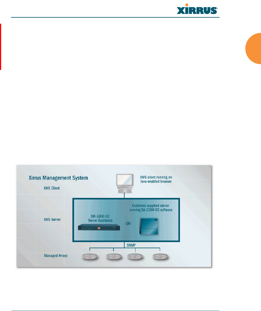
Xirrus Management System (XMS)
XMS is used for managing large Array deployments from a centralized
Web-based interface. The XMS server is available pre-installed on the
Xirrus XM-33xx-CC Management Appliance series, or as a software
package (XA-3300-CC) to be installed on your own server hardware.
Figure 2 illustrates the elements of the Xirrus Management System. Users
start the XMS client simply by entering the URL of the XMS server on a
web browser. The XMS server manages a number of Wi-Fi Arrays via
SNMP.
Figure 2. The Xirrus Management System

Wi-Fi Array
4 Introduction
If you need detailed information about this product, refer to the XMS
User’s Guide, part number 800-0007-001.
Xirrus Power over Gigabit Ethernet (PoGE)
The PoGE modules eliminate the need for running separate power
cabling. Additionally, an eight port module provides distributed power
to multiple Arrays, facilitating backup power when connected via a UPS.
Nomenclature
Throughout this User’s Guide, the Xirrus Wi-Fi Array is also referred to as simply
the Array. In some instances, the terms product and unit are also used. When
discussing specific products from the Xirrus family, the product name is used (for
example, XN16 or XS8). The Wi-Fi Array’s operating system is referred to as the
ArrayOS. The Web Management Interface for browser-based management of the
Array is referred to as WMI.
The XS series of Arrays have two types of radios — the 5 GHz 802.11a radios are
named a1 to a12 (for 16-port models). The 802.11a/b/g radios are named abg1 to
abg4, and they support both 2.4GHz and 5 GHz. The XN and XR4000 series of
Arrays also have two types of radios — the 5 GHz 802.11a/n radios are named an1
through an12 (for 16-port models). The 802.11a/b/g/n radios are named abgn1 to
abgn4, and they also support both 2.4GHz and 5 GHz. When referring to a port
that may be on either an XR4000, XN or XS model, the nomenclature abg(n) and
a(n) will be used, e.g., abg(n)2 or a(n)6.
The Xirrus Management System is referred to as XMS. The Power over Gigabit
Ethernet system may be referred to as PoGE.

Wi-Fi Array
Introduction 5
About this User’s Guide
This User’s Guide provides detailed information and procedures that will enable
wireless network administrators to install, configure and manage the Wi-Fi Array
so that end users can take full advantage of the product’s features and
functionality without technical assistance.
Organization
Topics and procedures are organized by function under the following chapter
headings:
Introduction
Provides a brief introduction to wireless technology, an overview of the
product, including its key features and benefits, and presents the product
specifications.
Installing the Wi-Fi Array
Defines prerequisites for deploying and installing the Array and provides
instructions to help you plan and complete a successful installation.
The Web Management Interface
Offers an overview of the product’s embedded Web Management
Interface, including its content and structure. It emphasizes what you
need to do to ensure that any configuration changes you make are
applied, and provides a list of restricted characters. It also includes
instructions for logging in to the Array with your Web browser.
Viewing Status on the Wi-Fi Array
Describes the status and statistics displays available on the Array using
its embedded Web Management Interface.
Configuring the Wi-Fi Array
Contains procedures for configuring the Array using its embedded Web
Management Interface.
Using Tools on the Wi-Fi Array
Contains procedures for using utility tools provided in the Web
Management Interface. It includes procedures for upgrading the system

Wi-Fi Array
6 Introduction
firmware, uploading and downloading configurations and other files,
using diagnostic tools, and resetting the Array to its factory defaults.
The Command Line Interface
Includes the commands and the command structure used by the Wi-Fi
Array’s Command Line Interface (CLI), and provides a procedure for
establishing a Telnet connection to the Array. This chapter also includes
some sample key configuration tasks using the CLI.
Appendix A: Servicing the Wi-Fi Array
Contains procedures for servicing the Array, including the removal and
reinstallation of major hardware components.
Appendix B: Quick Reference Guide
Contains the product’s factory default settings.
Appendix C: Technical Support
Offers guidance to resolve technical issues, including general hints and
tips to enhance your product experience, and a procedure for isolating
problems within an Array-enabled wireless network. Also includes
Frequently Asked Questions (FAQs) and Xirrus contact information.
Appendix D: Implementing PCI DSS
Discusses meeting security standards with the Array, including FIPS and
PCI DSS.
Appendix F: Notices
Contains the legal notices, licensing, and compliance statements for the
Array. Please read this section carefully.
Glossary of Terms
Provides an explanation of terms directly related to Xirrus product
technology, organized alphabetically.
Index
The index is a valuable information search tool. Use the index to locate
specific topics discussed in this User’s Guide. Simply click on any page
number in the index to jump to the referenced topic.

Wi-Fi Array
Introduction 7
Notes and Cautions
The following symbols are used throughout this User’s Guide:
Screen Images
Some screen images of the Web Management Interface have been modified for
clarity. For example, an image may have been cropped to highlight a specific area
of the screen, and/or sample data may be included in some fields.
Your User’s Guide as a PDF Document
This User’s Guide is also made available as a secure PDF (Portable Document
Format) file and can be viewed using the Adobe® Acrobat Reader® product. It
cannot be edited or modified. If you don’t have Acrobat Reader, you can
downloaded it free-of-charge from: http://www.adobe.com.
Hyperlinks
If you click on body text that appears in the color TEAL (with the exception of
headings or notes) the embedded hyperlink within the text will immediately take
you to the referenced destination. All internal and external cross-references,
including page numbers within the List of Figures and the Index, have associated
hyperlinks. After “jumping” to a referenced topic, if you want to return to the
previous page (reference source), simply click on Acrobat’s previous page button.
Window or Page?
Is a window a page, or is a page a window? There seems to be some dispute as to
what the correct term should be. For the sake of consistency, this document uses
the term Window when referring to how the Wi-Fi Array’s Web Management
Interface is displayed on your monitor.
This symbol is used for general notes that provide useful supplemental
information.
!This symbol is used for cautions. Cautions provide critical information that
may adversely affect the performance of the product.

Wi-Fi Array
8 Introduction
Why Choose the Xirrus Wi-Fi Array?
The deployment of wireless LANs is becoming increasingly common as
businesses strive for greater flexibility in the workplace and the need for
employee mobility rises. The only requirements for an effective wireless
deployment are a power source, a couple of screws, and a little imagination.
Wireless LAN is also fully compatible with standard Ethernet protocols, so
connectivity with existing wired infrastructures is transparent to users — they can
still access and use the same applications and network services that they use
when plugged into the company’s wired LAN infrastructure (it’s only the plug
that no longer exists).
Wireless LAN has come a long way in the past few years and now offers the
performance, reliability and security that Enterprise customers have come to
expect from their networks. The technology is being driven by four major IEEE
standards:
802.11a
Operates in the 5 GHz range with a maximum speed of 54 Mbps.
802.11b
Operates in the 2.4 GHz range with a maximum speed of 11 Mbps.
802.11g
Supports a higher transmission speed of 54 Mbps in the 2.4 GHz range
and is backwards compatible with 802.11b.
802.11n
Uses multiple antennas per radio to boost transmission speed as high as
300 Mbps, increasing throughput, range, and maximum number of users.
802.11n is backwards compatible with 802.11a/b/g.
Whether you have just a handful of users or thousands of users, wireless has the
scalability and flexibility to serve your needs.
Wi-Fi Array
Introduction 9
Wi-Fi Array Product Overview
Part of the family of Xirrus products, the Wi-Fi Array is a high capacity, multi-
mode device designed for the Enterprise market, with twice the range and up to
eight times the capacity of competitive wireless products.
Figure 3. Wi-Fi Array (XN16)
The Wi-Fi Array (regardless of the product model) is Wi-Fi® compliant and
simultaneously supports 802.11a, 802.11b and 802.11g clients. XR and XN model
arrays add the enhanced abilities of 802.11n to this combination. Active Enterprise
class features such as VLAN support and multiple SSID capability enable robust
network compatibility and a high level of scalability and system control.
The optional Xirrus Management System (XMS) allows global management of
hundreds of Arrays from a central location.
Multiple versions of the Array with different numbers of Integrated Access Points
(IAPs) support a variety of deployment applications: 16 IAPs (XN16, XS16),
12 IAPs (XN12), 8 IAPs (XR4820, XR4830, XN8, XS8), and 4 IAPs (XR4420,
XR4430, XN4, XS4).
Enterprise Class Security
The latest and most effective wireless encryption security standards, including
WPA (Wi-Fi Protected Access) and WPA2 with 802.11i AES (Advanced
Encryption Standard) are available on the Wi-Fi Array. In addition, the use of an
embedded RADIUS server (or 802.1x with an external RADIUS server) ensures
user authentication — multiple Arrays can authenticate to the optional XMS,
ensuring only authorized Arrays become part of the wireless network. With the
Wi-Fi Array
10 Introduction
Xirrus Advanced Feature Sets, rogue AP detection, site monitoring, and RF
spectrum analysis are performed in the background by the Array automatically.
Wi-Fi Array Product Family
The following tables provide an overview of the main features supported by the
Wi-Fi Array product family.
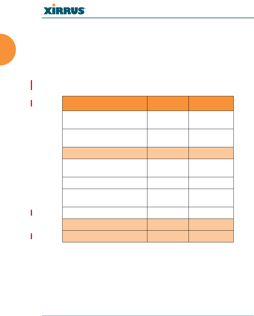
XR4000 Family of Arrays
Feature XR4820 XN4420
Number of
802.11a/b/g/n radios 44
Number of
802.11a/n radios 40
Tota l radi o s 8 4
Number of
integrated antennas 24 12
Integrated Wi-Fi switch ports 8 4
Integrated RF spectrum
analyzer, threat sensors Yes Yes
Uplink Ports 2 2
Wi-Fi bandwidth 2.4 Gbps 1.2 Gbps
Users supported 768 384
Wi-Fi Array
Introduction 11
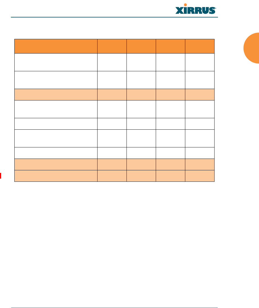
XN Family of Arrays
Feature XN16 XN12 XN8 XN4
Number of
802.11a/b/g/n radios 4444
Number of
802.11a/n radios 12840
Tota l radi o s 16 12 8 4
Number of
integrated antennas 48 36 24 12
Integrated Wi-Fi switch ports 16 12 8 4
Integrated RF spectrum
analyzer, threat sensors Yes Yes Yes Yes
Uplink Ports 2221
Wi-Fi bandwidth 4.8 Gbps 3.6 Gbps 2.4 Gbps 1.2 Gbps
Users supported 1536 1152 768 384
Wi-Fi Array
12 Introduction
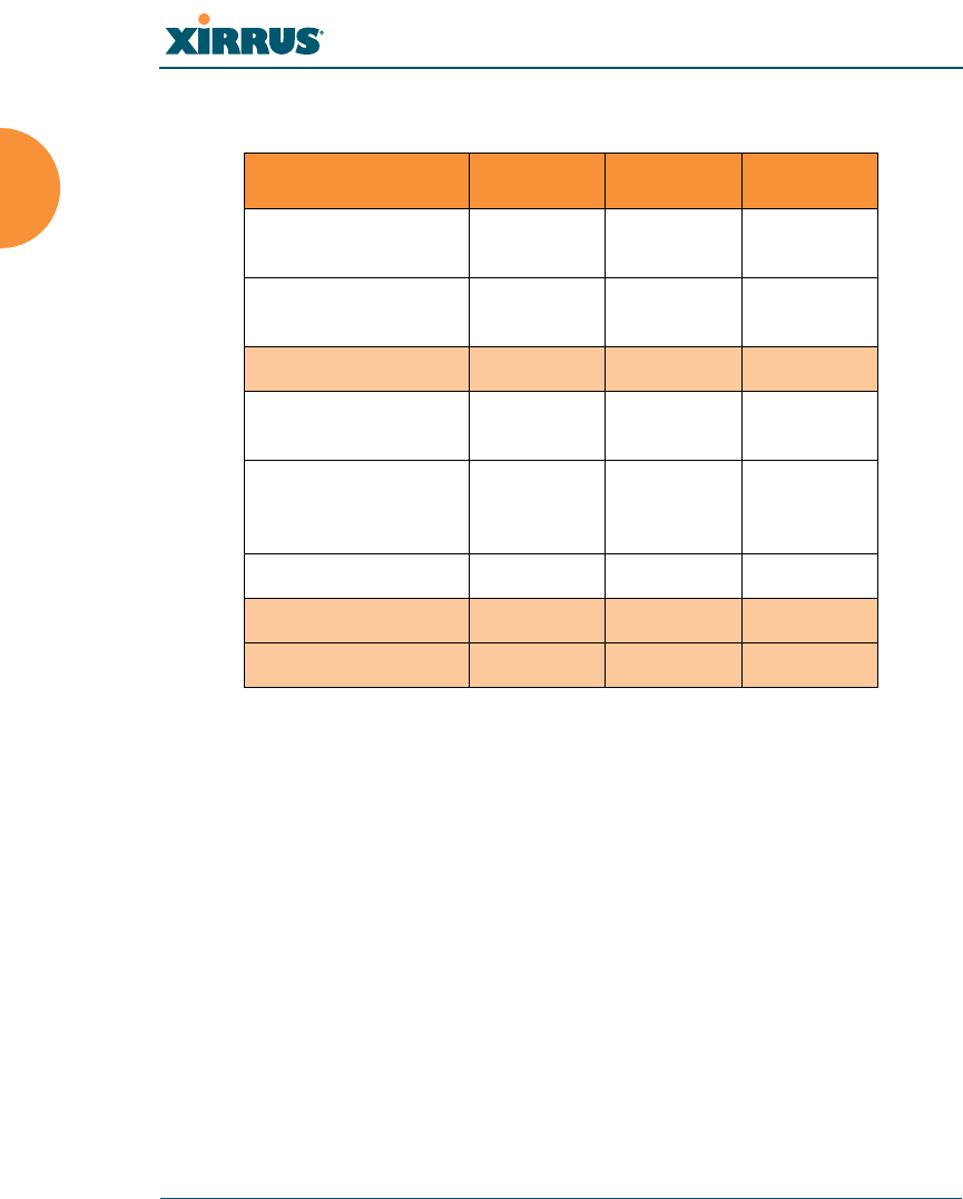
XS Family of Arrays
Feature XS16 XS8 XS4
Number of
802.11a/b/g radios 444
Number of
802.11a radios 12 4 0
Tot a l rad ios 16 8 4
Integrated Wi-Fi
switch ports 16 8 4
Integrated RF
spectrum analyzer
and threat sensors
Yes Yes Yes
Uplink Ports 221
Wi-Fi bandwidth 864 Mb 432 Mb 216 Mb
Users supported 1,024 512 256

Wi-Fi Array
Introduction 13
Deployment Flexibility
Xirrus’ unique multi-radio architecture generates 360 degrees of sectored high-
gain 802.11a/b/g/n or 802.11a/b/g coverage that provides extended range and
the highest possible data rates for a large volume of clients. Each sector can be
controlled automatically or manually, creating a pattern of wireless coverage
perfectly tailored to individual customer needs. For example:
Figure 4. Wireless Coverage Patterns
Figure 4 depicts the following two scenarios:
Full pattern coverage
All radios are activated with coverage spanning 360 degrees. If within
range, clients will always receive coverage regardless of their geographic
position relative to the Array.
Partial pattern coverage
If desired, the Wi-Fi Array can be deployed close to an exterior wall. In
this case, half of all available radios have been deactivated to prevent
redundant signals from “bleeding” beyond the site’s perimeter wall. This
configuration may also be used in those cases where you want to restrict
wireless coverage to selected areas of the building’s interior.
See also, “Flexible Coverage Schemes” on page 19.
outside wall
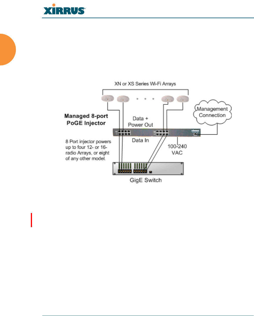
Wi-Fi Array
14 Introduction
Power over Gigabit Ethernet (PoGE)
The Xirrus XP1, XP2, and XP8 Power over Gigabit Ethernet modules provide
power to your Arrays over the same Cat 5e or Cat 6 cable used for data,
eliminating the need to run power cables and provide an AC power outlet in
proximity to each unit. Managed modules provide the ability to control power
using XMS.
Figure 5. XP8 - Power over Ethernet Usage
Specific models of the Array are compatible with specific PoGE modules. For
details, please see “Power over Gigabit Ethernet Compatibility Matrix” on
page 451.
Enterprise Class Management
The Wi-Fi Array can be configured with its default RF settings, or the RF settings
can be customized using the Array’s embedded Web Management Interface
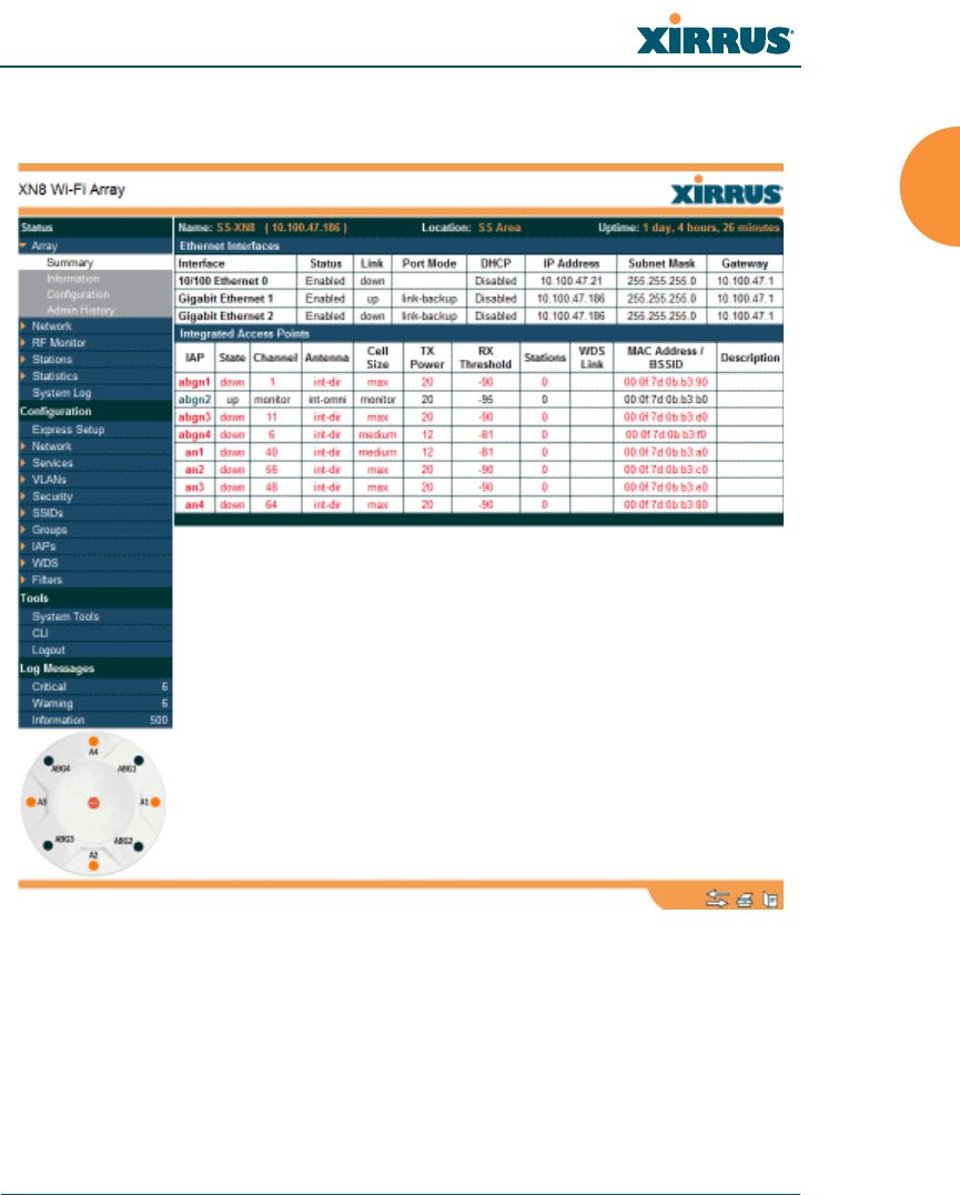
Wi-Fi Array
Introduction 15
(WMI). The WMI enables easy configuration and control from a graphical
console, along with a full compliment of troubleshooting tools and statistics.
Figure 6. WMI: Array Status
In addition, a fully featured Command Line Interface (CLI) offers IT professionals
a familiar management and control environment. SNMP (Simple Network
Management Protocol) is also supported to allow management from an SNMP
compliant management tool, such as the optional Xirrus Management System.

Wi-Fi Array
16 Introduction
For deployments of more than five Arrays, we recommend that you use the
Xirrus Management System (XMS). The XMS offers a rich set of features
for fine control over large deployments.
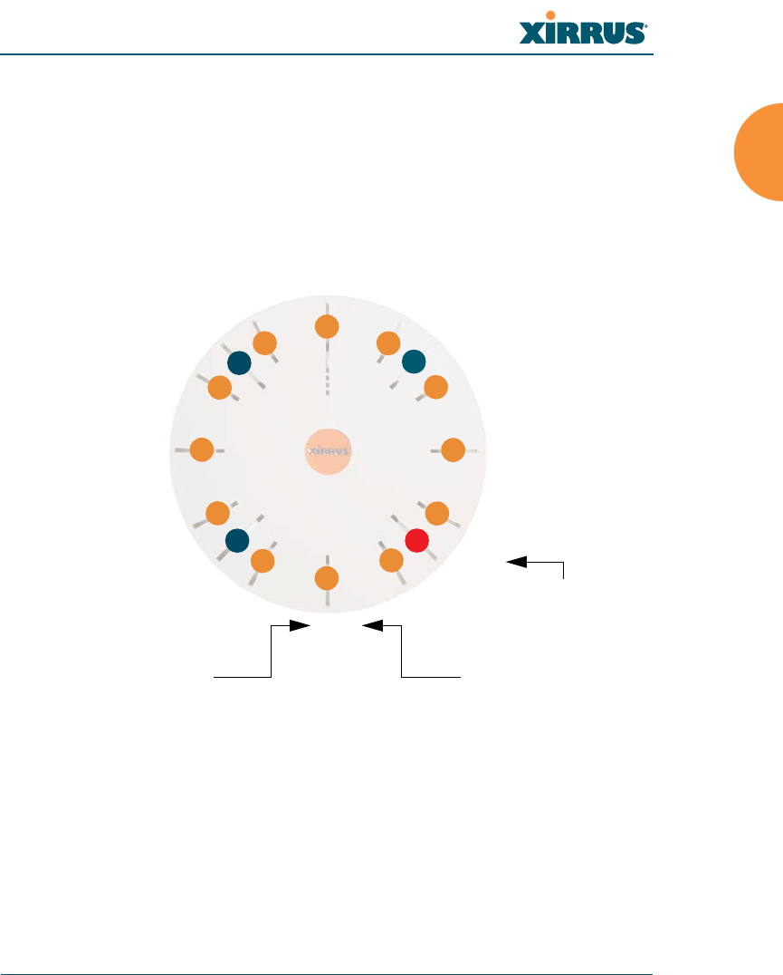
Wi-Fi Array
Introduction 17
Key Features and Benefits
This section describes some of the key product features and the benefits you can
expect when deploying the Wi-Fi Array (the XN16 product is highlighted in this
section).
High Capacity and High Performance
Figure 7. Layout of IAPs (XN16)
The XN16 version of the Wi-Fi Array (Figure 7) easily handles time-sensitive
traffic such as voice, and can enable wireless connectivity for 1,024 users. The unit
includes two Gigabit uplink ports for connection to the wired network. A total of
sixteen IAPs provides a maximum wireless capacity of 4.8 Gbps, which offers
ample reserves for the high demands of current and future applications. Of the
sixteen IAPs, twelve operate as 802.11a/n radios (5 GHz band), and four operate
as 802.11a/b/g/n radios (5 GHz or 2.4 GHz bands), providing backwards
compatibility with 802.11b and 802.11g.
an1
abgn1
an2
an3
an4
abgn2
an5
an6
an7
abgn3
an8
an9
an10
abgn4
an11
an12
Mode(s) IAP number
abgn2
(RF monitoring)
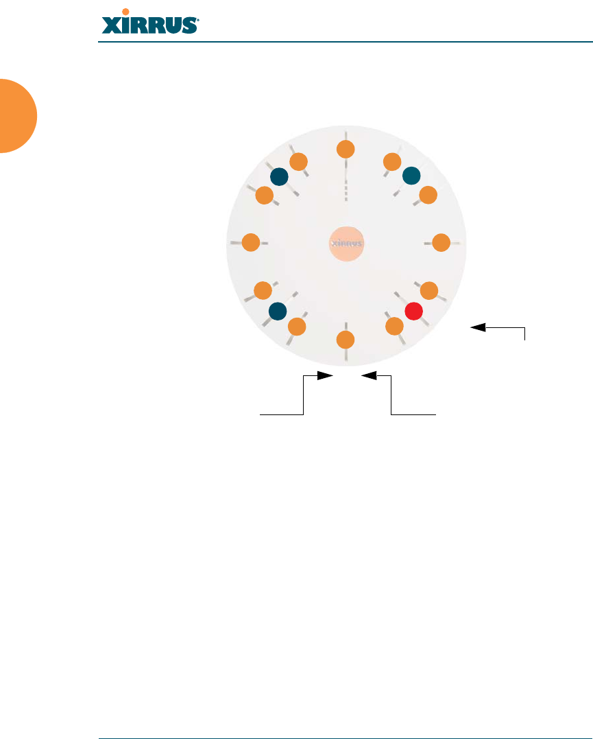
Wi-Fi Array
18 Introduction
In the recommended configuration, IAP (radio) abg(n)2 is configured in RF
monitoring and rogue AP detection mode.
Figure 8. Naming of IAPs (XS16)
Extended Coverage
One XN16 solution enables you to replace up to sixteen access points (includes
one omnidirectional IAP for monitoring the network). Fifteen IAP radios with
integrated directional antennas provide increased wireless range and enhanced
data rates in all directions. With a Wi-Fi Array deployed, far fewer access points
are needed and wired-like resiliency is delivered throughout your wireless
network. Your Wi-Fi Array deployment ensures:
Continuous connectivity if an IAP (radio) fails.
Continuous connectivity if an Array fails.
Continuous connectivity if a WDS link or switch fails.
Continuous connectivity if a Gigabit uplink or switch fails.
a1
abg1
a2
a3
a4
abg2
a5
a6
a7
abg3
a8
a9
a10
abg4
a11
a12
Mode(s) IAP number
abg2
(RF monitoring)
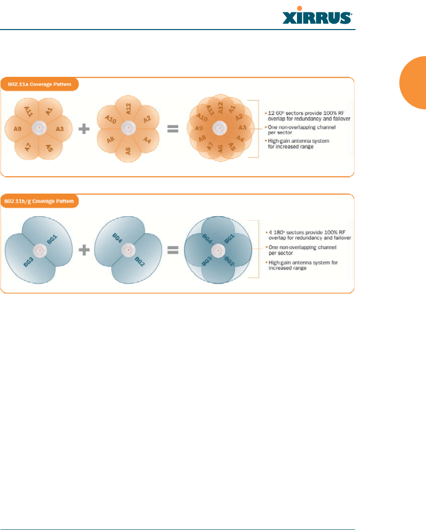
Wi-Fi Array
Introduction 19
Flexible Coverage Schemes
Your Wi-Fi Array offers flexible coverage schemes for each wireless technology.
Figure 9. Coverage Schemes (XS16 shown)
802.11a/n, 802.11a
Delivers 60° wireless coverage per IAP, with 6 dBi of gain.
802.11b/g/n, 802.11b/g
Delivers 180° wireless coverage, with 3 dBi of gain.
802.11a/b/g/n, 802.11a/b/g (monitor only)
Delivers 360° wireless coverage, with 2 dBi of gain.
Non-Overlapping Channels
Complete use of non-overlapping channels limits interference and delivers
maximum capacity. On the XN16, up to 16 non-overlapping channels are fully
utilized across the 5GHz and 2.4GHz spectrums (up to 12 across the 5GHz
spectrum plus up to 3 across the 2.4 GHz spectrum — typically, one additional
radio is used as a dedicated RF monitor).

Wi-Fi Array
20 Introduction
SDMA Optimization
SDMA (Spatial Division Multiple Access) technology provides full 360° coverage
while allowing independent channel and power output customization. Also
supports fast inter-zone handoffs for time-sensitive applications and roaming.
Fast Roaming
Utilizes the Xirrus Roaming Protocol (XRP) ensuring fast and seamless roaming
capabilities between IAPs or Arrays at both Layer 2 and Layer 3.
Easy Deployment
The Xirrus Management System (XMS) offers real time monitoring and
management capabilities for the wireless network — ideal for the Enterprise
market. It also allows you to import floor plans to help you plan your
deployment. The Xirrus Wi-Fi Array chassis has a plenum rated, lockable and
tamper resistant case.
Secure Wireless Access
Multiple layers of authentication and encryption ensure secure data
transmissions. The Wi-Fi Array is 802.11i compliant with line-rate encryption
support for 40 and 128 bit WEP, WPA and WPA2 with TKIP and AES encryption.
Authentication is provided via 802.1x, including PEAP, EAP-TLS, EAP-TTLS, and
LEAP (Lightweight Extensible Authentication Protocol) passthrough.
Applications Enablement
The Wi-Fi Array’s QoS (Quality of Service) functionality combined with true
switch capabilities enable high density video and Voice over Wireless LAN
deployments. Compliant with 802.1p and 802.1Q standards.
Advanced Feature Sets
The Wi-Fi Array offers a family of powerful functionality packages, including the
RF Performance Manager (RPM), RF Security Manager (RSM), and RF Analysis
Manager (RAM). These packages are separately licensed for operation on your
Array.

Wi-Fi Array
Introduction 21
Xirrus Advanced RF Performance Manager (RPM)
The Xirrus RPM optimizes the bandwidth usage and station performance of
802.11n Wi-Fi networks. Leveraging the multiple integrated access point (multi-
radio) design of the Xirrus Wi-Fi Array, RPM manages the allocation of wireless
bandwidth to wireless stations across multiple RF channels. The result maximizes
overall network performance with superior flexibility and capacity.
Today's wireless infrastructure is faced with ever increasing numbers and
variations of Wi-Fi enabled clients, whether in the form of notebooks, netbooks,
smart phones, IP phones, printers, projectors, cameras, RFID tags, etc. The advent
of higher speed 802.11n Wi-Fi and its increased use of the 5GHz spectrum adds to
the number of variables today's wireless networks must accommodate.
Backwards compatibility with older clients is crucial, however their operation in a
Wi-Fi network can significantly hinder the performance of faster clients. As an
example, 802.11b Wi-Fi stations communicate more than 10 times slower than
802.11n stations.
With each of the Array’s multiple radios operating on a different channel, RPM
selects the ideal radio for each station. High-speed stations are grouped together
on radios with other high speed stations, while lower speed stations are combined
with other lower speed stations. This ensures optimal performance for high-speed
802.11n stations without compromise.
The complete feature set of the RPM package includes:
WDS (Wireless Distribution System) for point-to-point communication
Wi-Fi Mode per IAP
Sharp Cell technology
Wireless Data Rate Optimization
Wireless Traffic Shaping
Wireless Voice Call Admission Control
Fast Layer 2 and 3 Roaming
Standby Mode

Wi-Fi Array
22 Introduction
Xirrus Advanced RF Security Manager (RSM)
The Xirrus RSM improves security and minimizes the risk in deploying 802.11n
wireless networks. Leveraging an integrated 24/7 threat sensor and hardware-
based encryption/decryption in each Array, RSM secures the Wi-Fi network from
multiple types of threats. The result delivers uncompromised overall network
security with superior flexibility and performance.
Today's Wi-Fi networks face a number of potential security threats in the form of
rogue access points, ad-hoc clients, unauthorized clients, wireless-based attacks,
eavesdropping, etc. As 802.11n is increasingly adopted in enterprise networks,
defending against these threats becomes more critical. With the Array’s dedicated
threat sensor radio scanning all channels in the 2.4GHz and 5GHz spectrums,
RSM searches for security threats and automatically mitigates them.
High performance encryption/decryption in the enterprise Wi-Fi network is a
must. The Wi-Fi network needs to support each client using the highest level of
encryption (WPA2 Enterprise/128 bit AES) and without degrading the overall
performance of the network. Xirrus incorporates hardware-based encryption/
decryption into each Array, delivering line-rate encryption at the edge of the
network instead of at a choke point within a centralized controller.
The complete feature set of the RSM package includes:
Wireless IDS/IPS (Intrusion Detection/Prevention System)
Wireless stateful firewall
User group policies
Authenticated guest access gateway
NAC integration
PCI audit compliance enforcement
Xirrus Advanced RF Analysis Manager (RAM)
The RF Advanced Analysis Manager (RAM) tests and troubleshoots 802.11n
wireless networks. The deployment of 802.11n presents a set of unique challenges
based on technology differences with legacy 802.11a/b/g networks, both on the
wireless infrastructure and client side. Xirrus' RAM equips each Wi-Fi Array with
a powerful set of tools and features to optimally tune and verify an 802.11n

Wi-Fi Array
Introduction 23
installation, as well as give IT administrators the ability to troubleshoot issues
that may occur within the wireless environment.
The 802.11n standard will continue to evolve over the next several years with
additional performance and optional functions, along with ongoing stream of
IEEE 802.11 amendments. This changing wireless landscape mandates that
appropriate tools are available to the user to analyze, optimize, and troubleshoot
their changing environments.
The distributed architecture of the Array enables the execution of powerful
wireless and networking analysis at the edge of the network where packets
traverse the wireless-to-wired boundary. The Array includes an embedded Wi-Fi
Controller with the necessary computing and memory resources to provide these
functions securely at the network's edge.
The key elements of the RAM package include:
RF Analysis – An embedded Spectrum Analyzer leverages the dedicated
threat sensor radio in each Wi-Fi Array to provide a continual view of
utilization, interference, and errors across all available Wi-Fi channels.
Packet Analysis – Integrated packet capture provides filterable views of
all traffic traversing on the wired and wireless interfaces of the Array.
Performance Analysis – Embedded traffic generation enables the
throughput of the Array’s wireless or wired interfaces to be analyzed.
Failure Recovery – Radio Assurance provides an automatic self-test and
self healing mechanism that ensures continuous system operation.
Netflow Support
Network Tools: ping, RADIUS ping, traceroute
Product Specifications — XR4400 and XR4800 Series

Wi-Fi Array
24 Introduction
??xxx Please review VERRRRRY carefully!!
Element XR4000 Series Specifications
Number of Users Maximum of 96 associated users per radio
XR48xx: 768 users per Array
XR44xx: 384 users per Array
Physical Diameter: 12.58 inches (31.95 cm)
Height: 2.58 inches (6.55 cm)
Weight: 4lbs (1.81 kg)
Environmental Operating Temperature:
0°C to 55°C
0% to 90% relative humidity (non-condensing)
Storage Temperature:
-20°C to 60°C
5% to 95% relative humidity (non-condensing)
System 700 MHz CPU
1 GB RAM
1 GB system flash
Integrated Switch 2.1 Gbps integrated wireless switch
Chassis Lockable mounting plate, Kensington lock slot
Electrical PoGE (DC) Input Power: Power over Gigabit
Ethernet — no splitter required, 48VDC,
Maximum 2A
Nominal Power:
XR48xx: 60W
XR44xx: 35W
See “Power over Gigabit Ethernet Compatibility
Matrix” on page 451.

Wi-Fi Array
Introduction 25
Interfaces Serial Console Port:
1 x RS232 – RJ45 connector, for local
configuration
Ethernet Interfaces:
2 x Gigabit 100/1000 Mbps uplink ports for link
aggregation, redundancy, or bridging
1 x Fast Ethernet 10/100 Mbps, for out of band
management
Status LEDs:
System status, Ethernet, Radio
Networking DHCP client, DHCP server (multiple DHCP
pools), DNS Client, NTP client, NAT
Management Xirrus Management System (XMS) — Layer 3
Element Management System
HTTPS Web Management Interface (WMI)
CLI via SSHv2, Telnet, local serial Console
Enable/disable management for any interface
Read-write and read-only admin accounts may
be authenticated via RADIUS
SNMP v2c, v3
Configuration Files — text-based files may be
imported, exported, or compared
NetFlow — IP flow information (traffic statistics
may be sent to an external Collector
FTP, TFTP
Syslog reporting for alerts/alarms — messages
may be stored on internal Syslog server or sent to
up to three external syslog servers.
Cisco Discovery Protocol (CDP) — obtain
protocol addresses and platform information for
neighboring devices
Element XR4000 Series Specifications

Wi-Fi Array
26 Introduction
Quality of Service
(QoS) Support
Multiple SSIDs:
16 unique SSIDs per Array
Each SSID beacons a unique BSSID per radio
VLAN and QoS settings for each SSID
VLANs:
Up to 16 VLANs, 802.1Q, 802.1p
Prioritization:
802.11e wireless prioritization
802.1p wired prioritization
Fair queuing of downstream traffic
Wireless Voice Support
Element XR4000 Series Specifications

Wi-Fi Array
Introduction 27
Security Wireless Encryption
Line speed, hardware-accelerated encryption
modes:
WPA TKIP
WPA2 AES
WEP 40/64
WEP 104/128
Wireless Authentication:
Open
Pre-shared Key
802.1X EAP
PEAP
EAP-TLS
EAP-TTLS
EAP-LEAP Pass-through
Web Page Redirect (Captive Portal)
MAC Address Access Control List (ACL)
CHAP, PAP
Firewall:
Integrated stateful-inspection, rules-based
firewall
Rogue AP detection and blocking:
Integrated Rogue AP detection and alerting via
dedicated internal RF Threat Sensor. Rogue AP
can be shielded
Integrated RADIUS Server:
Integrated 802.1x Authentication Server
supporting EAP-PEAP
Element XR4000 Series Specifications

Wi-Fi Array
28 Introduction
Security
(continued)
Time of Day Access:
Specify when access is allowed, per SSID or User
Group
Station-Station Blocking:
Station-to-Station traffic blocking option
Wireless Wireless Standards:
802.11a
802.11b
802.11d
802.11g
802.11e
802.11h
802.11i
802.11j
802.11n
Number of Radios: ??OK??
XR48xx: 4 x 802.11a/n radios
4 x 802.11a/b/g/n radios
Advanced RF design includes 36
integrated antennas
XR44xx: 4 x 802.11a/b/g/n radios
Advanced RF design includes 20
integrated antennas
Spectrum Analyzer:
1 integrated into Array
Element XR4000 Series Specifications

Wi-Fi Array
Introduction 29
Wireless
(continued)
Frequency Bands:
11a/n: 4.945 – 4.985 (restricted Public Safety
band)
11a/n: 5.15-5.25 GHz (UNII 1)
11a/n: 5.15-5.25 GHz (TELEC)
11a/n: 5.25-5.35 GHz (UNII 2)
11a/n: 5.470-5.725 (ETSI)
11a/n: 5.725-5.825 GHz (UNII 3)
11b/g/n: 2.412-2.462 GHz (FCC)
11b/g/n: 2.412-2.472 GHz (ETSI)
11b/g/n: 2.412-2.484 GHz (TELEC)
Channel Selection:
Manual and Automatic
802.11a/n Antennas
Integrated 6dBi, sectorized
802.11b/g/n Antennas
Integrated 3dBi, sectorized
Wi-Fi Monitoring:
1 Integrated Access Point can be set as a
dedicated Wi-Fi Threat Sensor
2 dBi 360° omni-directional antenna
802.11a/b/g/n External Antenna Connectors:
3 RP-TNC connectors (NOTE: TNC antenna
connection is not for outside plant connection.)
Performance Client Load Balancing
Automatic load balancing between system radios
Element XR4000 Series Specifications

Wi-Fi Array
30 Introduction
Compliance Electromagnetic:
ICES-003 (Canada)
EN 301.893 (Europe)
EN 301.489-1 and -17 (Europe)
Safety:
EN 60950
EN 50371 to 50385
CE Mark
Additional information in “Appendix F: Notices”
on page 467.
Certifications Wi-Fi Alliance: 802.11a/b/g/n, WPA, WPA2, and
extended EAP types. Our certifications may be
viewed here.
Additional information in “Appendix F: Notices”
on page 467.
Warranty Hardware:
Five Year Standard (extendable)
Software:
90 Days Standard (extendable)
Element XR4000 Series Specifications

Wi-Fi Array
Introduction 31
Product Specifications — XN16, XN12, and XN8
Element XN16/XN12/XN8 Specifications
Number of Users Maximum of 96 associated users per radio
XN16: 1536 users per Array
XN12: 1152 users per Array
XN8: 768 users per Array
Physical Diameter: 18.65 inches (47.37 cm)
Height: 3.87 inches (9.83 cm)
Weight: 10 lbs (3.63 kg)
Environmental Operating Temperature:
0°C to 55°C
0% to 90% relative humidity (non-condensing)
Storage Temperature:
-20°C to 60°C
5% to 95% relative humidity (non-condensing)
System 1 GHz CPU
1 GB RAM
1 GB system flash
Integrated Switch 2.1 Gbps integrated wireless switch
Chassis Lockable mounting plate, Kensington lock slot

Wi-Fi Array
32 Introduction
Electrical XN8, XN12, XN16 powered by PoGE only
PoGE (DC) Input Power: Power over Gigabit
Ethernet — no splitter required, 48VDC,
Maximum 2A
Nominal Power:
XN16: 90W
XN12: 75W
XN8: 60W
All Models:
For PoGE, see “Power over Gigabit Ethernet
Compatibility Matrix” on page 451.
Interfaces Serial Console Port:
1 x RS232 – RJ45 connector, for local
configuration
Ethernet Interfaces:
2 x Gigabit 100/1000 Mbps uplink ports for link
aggregation, redundancy, or bridging
1 x Fast Ethernet 10/100 Mbps, for out of band
management
Status LEDs:
System status, Ethernet, Radio
Networking DHCP client, DHCP server (multiple DHCP
pools), DNS Client, NTP client, NAT
Element XN16/XN12/XN8 Specifications

Wi-Fi Array
Introduction 33
Management Xirrus Management System (XMS) — Layer 3
Element Management System
HTTPS Web Management Interface (WMI)
CLI via SSHv2, Telnet, local serial Console
Enable/disable management for any interface
Read-write and read-only admin accounts may
be authenticated via RADIUS
SNMP v2c, v3
Configuration Files — text-based files may be
imported, exported, or compared
NetFlow — IP flow information (traffic statistics
may be sent to an external Collector
FTP, TFTP
Syslog reporting for alerts/alarms — messages
may be stored on internal Syslog server or sent to
up to three external syslog servers.
Cisco Discovery Protocol (CDP) — obtain
protocol addresses and platform information for
neighboring devices
Quality of Service
(QoS) Support
Multiple SSIDs:
16 unique SSIDs per Array
Each SSID beacons a unique BSSID per radio
VLAN and QoS settings for each SSID
VLANs:
Up to 16 VLANs, 802.1Q, 802.1p
Prioritization:
802.11e wireless prioritization
802.1p wired prioritization
Fair queuing of downstream traffic
Wireless Voice Support
Element XN16/XN12/XN8 Specifications

Wi-Fi Array
34 Introduction
Security Wireless Encryption
Line speed, hardware-accelerated encryption
modes:
WPA TKIP
WPA2 AES
WEP 40/64
WEP 104/128
Wireless Authentication:
Open
Pre-shared Key
802.1X EAP
PEAP
EAP-TLS
EAP-TTLS
EAP-LEAP Pass-through
Web Page Redirect (Captive Portal)
MAC Address Access Control List (ACL)
CHAP, PAP
Firewall:
Integrated stateful-inspection, rules-based
firewall
Rogue AP detection and blocking:
Integrated Rogue AP detection and alerting via
dedicated internal RF Threat Sensor. Rogue AP
can be shielded
Integrated RADIUS Server:
Integrated 802.1x Authentication Server
supporting EAP-PEAP
Element XN16/XN12/XN8 Specifications

Wi-Fi Array
Introduction 35
Security
(continued)
Time of Day Access:
Specify when access is allowed, per SSID or User
Group
Station-Station Blocking:
Station-to-Station traffic blocking option
Wireless Wireless Standards:
802.11a
802.11b
802.11d
802.11g
802.11e
802.11h
802.11i
802.11j
802.11n
Number of Radios:
XN16: 12 x 802.11a/n radios
4 x 802.11a/b/g/n radios
Only 12 radios should be used as 802.11a/n
radios (i.e., 5 GHz band) concurrently.
48 integrated antennas
XN12: 8 x 802.11a/n radios
4 x 802.11a/b/g/n radios
36 integrated antennas
XN8: 4 x 802.11a/n radios
4 x 802.11a/b/g/n radios
Advanced RF design includes 36
integrated antennas
Spectrum Analyzer:
1 integrated into Array
Element XN16/XN12/XN8 Specifications

Wi-Fi Array
36 Introduction
Wireless
(continued)
Frequency Bands:
11a/n: 4.945 – 4.985 (restricted Public Safety
band)
11a/n: 5.15-5.25 GHz (UNII 1)
11a/n: 5.15-5.25 GHz (TELEC)
11a/n: 5.25-5.35 GHz (UNII 2)
11a/n: 5.470-5.725 (ETSI)
11a/n: 5.725-5.825 GHz (UNII 3)
11b/g/n: 2.412-2.462 GHz (FCC)
11b/g/n: 2.412-2.472 GHz (ETSI)
11b/g/n: 2.412-2.484 GHz (TELEC)
Channel Selection:
Manual and Automatic
802.11a/n Antennas
Integrated 6dBi, sectorized
802.11b/g/n Antennas
Integrated 3dBi, sectorized
Wi-Fi Monitoring:
1 Integrated Access Point can be set as a
dedicated Wi-Fi Threat Sensor
2 dBi 360° omni-directional antenna
802.11a/b/g/n External Antenna Connectors:
3 RP-TNC connectors (NOTE: TNC antenna
connection is not for outside plant connection.)
Performance Client Load Balancing
Automatic load balancing between system radios
Element XN16/XN12/XN8 Specifications

Wi-Fi Array
Introduction 37
Compliance Electromagnetic:
ICES-003 (Canada)
EN 301.893 (Europe)
EN 301.489-1 and -17 (Europe)
Safety:
EN 60950
EN 50371 to 50385
CE Mark
Additional information in “Appendix F: Notices”
on page 467.
Certifications Wi-Fi Alliance: 802.11a/b/g/n, WPA, WPA2, and
extended EAP types. Our certifications may be
viewed here.
Additional information in “Appendix F: Notices”
on page 467.
Warranty Hardware:
Five Year Standard (extendable)
Software:
90 Days Standard (extendable)
Element XN16/XN12/XN8 Specifications

Wi-Fi Array
38 Introduction
Product Specifications — XN4
Element XN4 Specifications
Number of Users Maximum of 96 associated users per radio,
384 users per XN4
Physical Diameter: 12.58 inches (31.95 cm)
Height: 2.58 inches (6.55 cm)
Weight: 4lbs (1.81 kg)
Environmental Operating Temperature:
0°C to 55°C
0% to 90% relative humidity (non-condensing)
Storage Temperature:
-20°C to 60°C
5% to 95% relative humidity (non-condensing)
System 825 MHz CPU
512 MB RAM
1 GB system flash
Integrated Switch 2.1 Gbps integrated wireless switch
Chassis Lockable mounting plate, Kensington lock slot
Electrical XN4 supports Power over Gigabit Ethernet
(PoGE) only, no splitter required
PoGE (DC) Input Power: 48VDC, Maximum 2A
Nominal Power: 35W
For PoGE, see “Power over Gigabit Ethernet
Compatibility Matrix” on page 451.

Wi-Fi Array
Introduction 39
Interfaces Serial Console Port:
1 x RS232 – RJ45 connector, for local
configuration
Ethernet Interfaces:
1 x Gigabit 100/1000 Mbps uplink port
Status LEDs:
System status, Ethernet, Radio
Networking DHCP client, DHCP server (multiple DHCP
pools), DNS Client, NTP client, NAT
Management Xirrus Management System (XMS) — Layer 3
Element Management System
HTTPS Web Management Interface (WMI)
CLI via SSHv2, Telnet, local serial Console
Enable/disable management for any interface
Read-write and read-only admin accounts may
be authenticated via RADIUS
SNMP v2c, v3
Configuration Files — text-based files may be
imported, exported, or compared
NetFlow — IP flow information (traffic statistics
may be sent to an external Collector
FTP, TFTP
Syslog reporting for alerts/alarms — messages
may be stored on internal Syslog server or sent to
up to three external syslog servers.
Cisco Discovery Protocol (CDP) — obtain
protocol addresses and platform information for
neighboring devices
Element XN4 Specifications

Wi-Fi Array
40 Introduction
Quality of Service
(QoS) Support
Multiple SSIDs:
16 unique SSIDs per Array
Each SSID beacons a unique BSSID per radio
VLAN and QoS settings for each SSID
VLANs:
Up to 16 VLANs, 802.1Q, 802.1p
Prioritization:
802.11e wireless prioritization
802.1p wired prioritization
Fair queuing of downstream traffic
Wireless Voice Support
Element XN4 Specifications

Wi-Fi Array
Introduction 41
Security Wireless Encryption
Line speed, hardware-accelerated encryption
modes:
WPA TKIP
WPA2 AES
WEP 40/64
WEP 104/128
Wireless Authentication:
Open
Pre-shared Key
802.1X EAP
PEAP
EAP-TLS
EAP-TTLS
EAP-LEAP Pass-through
Web Page Redirect (Captive Portal)
MAC Address Access Control List (ACL)
CHAP, PAP
Firewall:
Integrated stateful-inspection, rules-based
firewall
Rogue AP detection and blocking:
Integrated Rogue AP detection and alerting via
dedicated internal RF Threat Sensor. Rogue AP
can be shielded
Integrated RADIUS Server:
Integrated 802.1x Authentication Server
supporting EAP-PEAP
Element XN4 Specifications

Wi-Fi Array
42 Introduction
Security
(continued)
Time of Day Access:
Specify when access is allowed, per SSID or User
Group
Station-Station Blocking:
Station-to-Station traffic blocking option
Wireless Wireless Standards:
802.11a
802.11b
802.11d
802.11g
802.11e
802.11h
802.11i
802.11j
802.11n
Number of Radios:
4 x 802.11a/b/g/n radios
Advanced RF design includes 20 integrated
antennas
Spectrum Analyzer:
1 integrated into Array
Element XN4 Specifications

Wi-Fi Array
Introduction 43
Wireless
(continued)
Frequency Bands:
11a/n: 4.945 – 4.985 (restricted Public Safety
band)
11a/n: 5.15-5.25 GHz (UNII 1)
11a/n: 5.15-5.25 GHz (TELEC)
11a/n: 5.25-5.35 GHz (UNII 2)
11a/n: 5.470-5.725 (ETSI)
11a/n: 5.725-5.825 GHz (UNII 3)
11b/g/n: 2.412-2.462 GHz (FCC)
11b/g/n: 2.412-2.472 GHz (ETSI)
11b/g/n: 2.412-2.484 GHz (TELEC)
Channel Selection:
Manual and Automatic
802.11a/n Antennas
Integrated 3dBi, sectorized
802.11b/g/n Antennas
Integrated 1dBi, sectorized
Wi-Fi Monitoring:
1 Integrated Access Point can be set as a
dedicated Wi-Fi Threat Sensor
2 dBi 360° omni-directional antenna
802.11a/b/g/n External Antenna Connectors:
1 RP-TNC connector (NOTE: TNC antenna
connection is not for outside plant connection.)
Performance Client Load Balancing
Automatic load balancing between system radios
Element XN4 Specifications

Wi-Fi Array
44 Introduction
Compliance Electromagnetic:
ICES-003 (Canada)
EN 301.893 (Europe)
EN 301.489-1 and -17 (Europe)
Safety:
EN 60950
EN 50371 to 50385
CE Mark
Additional information in “Appendix F: Notices”
on page 467.
Certifications Wi-Fi Alliance: 802.11a/b/g/n, WPA, WPA2, and
extended EAP types. Our certifications may be
viewed here.
Additional information in “Appendix F: Notices”
on page 467.
Warranty Hardware:
Five Year Standard (extendable)
Software:
90 Days Standard (extendable)
Element XN4 Specifications

Wi-Fi Array
Introduction 45
Product Specifications — XS16 and XS8
Element XS16/XS8 Specifications
Number of Users Maximum of 64 associated users per radio
1024 users per Array (XS16)
512 users per Array (XS8)
Physical Diameter: 18.65 inches (47.37 cm)
Height: 3.87 inches (9.83 cm)
Weight: 8lbs (3.63 kg)
Environmental Operating Temperature:
-10°C to 50°C
0% to 90% relative humidity (non-condensing)
Storage Temperature:
-20°C to 60°C
5% to 95% relative humidity (non-condensing)
System 1 GHz CPU
1 GB RAM
1 GB system flash
Expansion slot for future options
Interfaces Serial:
1 x RS232 – RJ45 connector
Ethernet Interfaces:
2 x Gigabit 100/1000 Mbps w/failover
1 x Fast Ethernet 10/100 Mbps
Status LEDs:
System status, Ethernet, Radio

Wi-Fi Array
46 Introduction
Electrical XS16/XS8:
Each Array supports both AC and PoGE
AC Input Power: 90-265VAC at 47-63Hz
PoGE Input Power: Power over Gigabit Ethernet —
no splitter required, 48VDC
Nominal Power:
XS16: 70W
XS8: 45W
For PoGE, see “Power over Gigabit Ethernet
Compatibility Matrix” on page 451.
Networking DHCP client, DHCP server, NTP client, NAT
VLAN Support 802.1Q, 802.1p VLAN
Supports up to 16 VLANs
Multiple SSID
Support
Allows up to 16 separate SSIDs to be defined with
map security, VLAN and QoS settings for each
SSID
Performance Client Load Balancing
Automatic load balancing between system radios
Quality of Service:
802.1p wired traffic prioritization
Wireless packet prioritization
MAP CoS to TCID
Fair queuing of downstream traffic
Element XS16/XS8 Specifications

Wi-Fi Array
Introduction 47
Security Wireless Security:
WEP 40bit/128bit encryption
WPA and WPA2 with TKIP and AES encryption
Rogue AP detection, with alerts and classification
User and System Authentication:
WPA and WPA2 Pre-Shared Key authentication
Internal RADIUS Server, supports EAP-PEAP only
802.1x EAP-TLS
802.1x EAP-TTLS/MSCHAPv2
802.1x PEAPv0/EAP-MSCHAPv2
802.1x PEAPv1/EAP-GTC
802.1x EAP-SIM
802.1x EAP-LEAP Passthrough
External RADIUS servers
Authentication of Wi-Fi Arrays to the Xirrus
Management System (XMS)
Element XS16/XS8 Specifications

Wi-Fi Array
48 Introduction
Wireless Number of Radios:
XS16: 12 x 802.11a radios
4 x 802.11a/b/g radios
Only 12 radios should be used as 802.11a radios
concurrently.
XS8: 4 x 802.11a radios
4 x 802.11a/b/g radios
Wireless Standards:
802.11a/b/g and g-only mode
802.11e, 802.11i
Channel Selection:
Manual and Automatic
Frequency Bands:
11a: 4.945 – 4.985 (restricted Public Safety band)
11a: 5.15-5.25 GHz (UNII 1)
11a: 5.15-5.25 GHz (TELEC)
11a: 5.25-5.35 GHz (UNII 2)
11a: 5.470-5.725 (ETSI)
11a: 5.725-5825 GHz (UNII 3)
11b/g: 2.412-2.462 GHz (FCC)
11b/g: 2.412-2.472 GHz (ETSI)
11b/g: 2.412-2.484 GHz (TELEC)
Antennas (XS16):
12 x internal 6 dBi 60° 802.11a sectorized
4 x internal 3 dBi 180° 802.11b/g sectorized
1 x internal 2 dBi 360° omni-directional (for RF
monitoring)
3 x external RP-TNC connectors for three 802.11a/
b/g radios *
Element XS16/XS8 Specifications

Wi-Fi Array
Introduction 49
Wireless
(continued)
Antennas (XS8):
4 x internal 6 dBi 60° 802.11a sectorized
4x internal 3 dBi 180° 802.11b/g sectorized
1 x internal 2 dBi 360° omni-directional (for RF
monitoring)
3 x external RP-TNC connectors for three 802.11a/
b/g radios *
Radio Approvals:
FCC (United States) and EN 301.893 (Europe)
* Note: External RP-TNC antenna connectors are
not for outside plant connection.
Management Web-based HTTPS
SNMP v2c, v3
CLI via SSHv2 or Telnet
FTP
TFTP
Serial
Xirrus Management System (XMS)
Syslog reporting for alerts/alarms
Compliance UL / cUL 60950 and EN 60950
FCC Part 15.107 and 15109, Class A
EN 301.489 (Europe)
EN60601 EU medical equipment directive for EMC
Additional information in “Appendix F: Notices”
on page 467.
Element XS16/XS8 Specifications

Wi-Fi Array
50 Introduction
Certifications Wi-Fi Alliance: 802.11a/b/g, WPA, WPA2, and
extended EAP types. Our certifications may be
viewed here.
Federal Information Processing Standard (FIPS)
Publication 140 -2, Level 2.
Payment Card Industry Data Security Standard
(PCI DSS) verified by VeriSign
Additional information in “Appendix F: Notices”
on page 467.
Warranty One year (hardware and software)
Element XS16/XS8 Specifications

Wi-Fi Array
Introduction 51
Product Specifications — XS4
Element XS4 Specifications
Number of Users Maximum of 64 associated users per radio (256
users per Array)
Physical Diameter: 12.58 inches (31.95 cm)
Height: 2.58 inches (6.55 cm)
Weight: 4lbs (1.81 kg)
Environmental Operating Temperature:
-10°C to 50°C
0% to 90% relative humidity (non-condensing)
Storage Temperature:
-20°C to 60°C
5% to 95% relative humidity (non-condensing)
System 825 MHz CPU (XS4)
512 MB RAM, expandable (XS4)
512 MB system flash, expandable
Expansion slot for future options
Electrical XS4:
Each Array supports both AC and PoGE
AC Input Power: 90-265VAC at 47-63Hz
Nominal power usage: 27W
Power over Gigabit Ethernet (PoGE): all 4-port
models work with all Xirrus PoGE modules,
splitter required, 48VDC
See “Power over Gigabit Ethernet Compatibility
Matrix” on page 451.

Wi-Fi Array
52 Introduction
Interfaces Serial:
1 x RS232 – RJ45 connector
Ethernet Interfaces:
1 x Gigabit 100/1000 Mbps
Status LEDs:
System status, Ethernet, Radio
Management Web-based HTTPS
SNMP v2c, v3
CLI via SSHv2 or Telnet
FTP
TFTP
Serial
Xirrus Management System (XMS)
Syslog reporting for alerts/alarms
Networking DHCP client, DHCP server, NTP client, NAT
VLAN Support 802.1Q, 802.1p VLAN
Supports up to 16 VLANs
Multiple SSID
Support
Allows up to 16 separate SSIDs to be defined with
map security, VLAN and QoS settings for each
SSID
Performance Client Load Balancing
Automatic load balancing between system radios
Quality of Service:
802.1p wired traffic prioritization
Wireless packet prioritization
MAP CoS to TCID
Fair queuing of downstream traffic
Element XS4 Specifications

Wi-Fi Array
Introduction 53
Security Wireless Security:
WEP 40bit/128bit encryption
WPA and WPA2 with TKIP and AES encryption
Rogue AP detection, with alerts and classification
User and System Authentication:
WPA Pre-Shared Key authentication
Internal RADIUS Server, supports EAP-PEAP only
802.1x EAP-TLS
802.1x EAP-TTLS/MSCHAPv2
802.1x PEAPv0/EAP-MSCHAPv2
802.1x PEAPv1/EAP-GTC
802.1x EAP-SIM
802.1x EAP-LEAP Passthrough
External RADIUS servers
Authentication of Wi-Fi Arrays to the Xirrus
Management System (XMS)
Element XS4 Specifications

Wi-Fi Array
54 Introduction
Wireless Number of Radios:
4 x 802.11a/b/g radios
Wireless Standards:
802.11a/b/g and g-only mode
802.11e, 802.11i
Channel Selection:
Manual and Automatic
Frequency Bands:
11a: 4.945 – 4.985 (restricted Public Safety band)
11a: 5.15-5.25 GHz (UNII 1)
11a: 5.15-5.25 GHz (TELEC)
11a: 5.25-5.35 GHz (UNII 2)
11a: 5.470-5.725 (ETSI)
11a: 5.725-5825 GHz (UNII 3)
11b/g: 2.412-2.462 GHz (FCC)
11b/g: 2.412-2.472 GHz (ETSI)
11b/g: 2.412-2.484 GHz (TELEC)
Radio Approvals:
FCC (United States) and EN 301.893 (Europe)
Compliance UL / cUL 60950 and EN 60950
FCC Part 15.107 and 15109, Class A
EN 301.489 (Europe)
EN60601 EU medical equipment directive for EMC
Additional information in “Appendix F: Notices”
on page 467.
Element XS4 Specifications

Wi-Fi Array
Introduction 55
Certifications Wi-Fi Alliance: 802.11a/b/g, WPA, WPA2, and
extended EAP types. Our certifications may be
viewed here.
Federal Information Processing Standard (FIPS)
Publication 140 -2, Level 2.
Payment Card Industry Data Security Standard
(PCI DSS) verified by VeriSign
Additional information in “Appendix F: Notices”
on page 467.
Warranty One year (hardware and software)
Element XS4 Specifications

Wi-Fi Array
56 Introduction

Wi-Fi Array
Installing the Wi-Fi Array 57
Installing the Wi-Fi Array
The instructions for completing a successful installation include the following
topics:
“Installation Prerequisites” on page 57.
“Planning Your Installation” on page 60.
“Installation Workflow” on page 94.
“Installing Your Wi-Fi Array” on page 96.
“Powering Up the Wi-Fi Array” on page 100.
“Establishing Communication with the Array” on page 103.
“Performing the Express Setup Procedure” on page 106.
Installation Prerequisites
Your Wi-Fi Array deployment requires the presence of hardware and services in
the host wired/wireless network, including:
Power Source
Most Arrays are powered via Xirrus Power over Gigabit Ethernet. PoGE
supplies power over the same Cat 5e or Cat 6 cable used for data, thus
reducing cabling and installation effort. PoGE power injector modules are
available in 1-, 2-, and 8-port configurations and are typically placed near
your Gigabit Ethernet switch. An AC outlet is required for each injector
module. Current Array models have integrated splitters, so no separate
splitter is required.
Specific models of the Array are compatible with specific PoGE modules.
For details, please see “Power over Gigabit Ethernet Compatibility
Matrix” on page 451.
If your Arrays are equipped to accept AC power (and you are not using
PoGE), you need a dedicated power outlet to supply AC power to each
unit deployed at the site.

Wi-Fi Array
58 Installing the Wi-Fi Array
Ethernet port
You need at least one 100/1000 BaseT port to establish wired Gigabit
Ethernet connectivity (via the product’s Gigabit 1 or Gigabit 2 port) and
one 10/100 BaseT port (if desired) for product management.
Secure Shell (SSH) utility
To establish secure remote command line access to the Array, you need a
Secure Shell (SSH) utility, such as PuTTY. The utility must be configured
to use SSH-2, since the Array will only allow SSH-2 connections.
Secure Web browser
Either Internet Explorer (version 6.0 or higher), Netscape Navigator
(version 7.0 or higher), or Mozilla Firefox (version 1.01 or higher).
A secure Web browser is required for Web-based management of the
Array. The browser must be on the same subnet as the Array, or you must
set a static route for management as described in the warning above.
Serial connection capability
To connect directly to the console port on the Array, your computer must
be equipped with a male 9-pin serial port and terminal emulation
software (for example, HyperTerminal). The Xirrus Array only supports
serial cable lengths up to 25’ per the RS-232 specification.
!The Array’s Ethernet ports should be connected to an Ethernet switch, not
an Ethernet hub — if a hub is used, we recommend that you connect only
one Ethernet port.
!The Gigabit1 Ethernet interface is the primary port for both data and
management traffic. If a single Ethernet connection is used, it must be
connected to the Gigabit1 Ethernet interface. See also, “Port Failover
Protection” on page 80.
The 10/100 Ethernet Port may be used for managing the Array out of
band from the Gigabit Ethernet ports. The 10/100 port will route only
management traffic, using a static route that may be configured for this
interface. See “interface” on page 370.
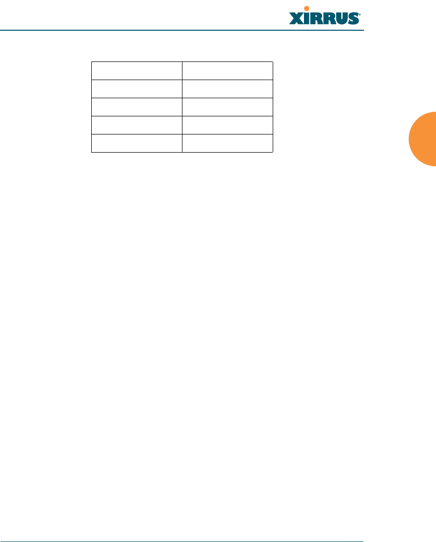
Wi-Fi Array
Installing the Wi-Fi Array 59
Use the following settings when establishing a serial connection:
Optional Network Components
The following network components are optional.
Xirrus Management System (XMS)
The optional XMS offers powerful management features for small or large
Wi-Fi Array deployments.
External RADIUS server
Although your Array comes with an embedded RADIUS server, for
802.1x authentication in large deployments you may want to add an
external RADIUS server.
Client Requirements
The Wi-Fi Array should only be used with Wi-Fi certified client devices.
See Also
Coverage and Capacity Planning
Deployment Examples
Failover Planning
Planning Your Installation
Bits per second 115,200
Data bits 8
Parity None
Stop bits 1
Flow control None

Wi-Fi Array
60 Installing the Wi-Fi Array
Planning Your Installation
This section provides guidelines and examples to help you plan your Xirrus Wi-Fi
Array deployment to achieve the best overall coverage and performance. We
recommend you conduct a site survey to determine the best location and settings
for each Array you install.
The following topics are discussed:
“General Deployment Considerations” on page 60
“Coverage and Capacity Planning” on page 62
“IEEE 802.11n Deployment Considerations” on page 72
“Failover Planning” on page 80
“Power Planning” on page 82
“Security Planning” on page 83
“Port Requirements” on page 86
“Network Management Planning” on page 89
“WDS Planning” on page 90
“Common Deployment Options” on page 93
General Deployment Considerations
The Wi-Fi Array’s unique multi-radio architecture generates 360 degrees of
sectored high-gain 802.11a/b/g/n or 802.11a/b/g coverage that provides
extended range. However, the number, thickness and location of walls, ceilings or
other objects that the wireless signals must pass through may affect the range.
Typical ranges vary depending on the types of materials and background RF
(radio frequency) noise at your location. To maximize wireless range, follow these
basic guidelines:
1. Keep the number of walls and ceilings between the Array and your
receiving devices to a minimum — each wall or ceiling can reduce the
For a complete discussion of implementing Voice over Wi-Fi on the Array,
see the Xirrus Voice over Wi-Fi Application Note in the Xirrus Library.
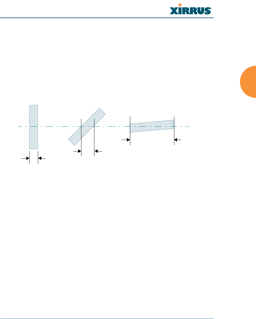
Wi-Fi Array
Installing the Wi-Fi Array 61
wireless range from between 3 and 90 feet (1 to 30 meters). Position your
devices so that the number of walls or ceilings is minimized.
2. Be aware of the direct line between each device. For example, a wall that
is 1.5 feet thick (half a meter) at 90° is actually almost 3 feet thick (or 1
meter) when viewed at a 45° angle. At an acute 2° degree angle the same
wall is over 42 feet (or 14 meters) thick! For best reception, try to ensure
that your wireless devices are positioned so that signals will travel
straight through a wall or ceiling.
Figure 10. Wall Thickness Considerations
3. Try to position wireless client devices so that the signal passes through
drywall (between studs) or open doorways and not other materials that
can adversely affect the wireless signal.
See Also
Coverage and Capacity Planning
Deployment Examples
Common Deployment Options
Installation Prerequisites
90° 45°
1.5 feet/
.5 m ~ 3 feet/
1 m
> 42 feet\
14 m
2°
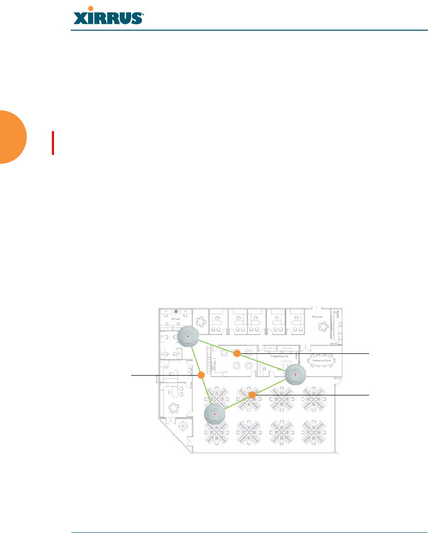
Wi-Fi Array
62 Installing the Wi-Fi Array
Coverage and Capacity Planning
This section considers coverage and capacity for your deployment(s), including
placement options, RF patterns and cell sizes, area calculations, roaming
considerations, and channel allocations.
Placement
Use the following guidelines when considering placement options:
1. The best placement option for the Array is ceiling-mounted within an
open plan environment (cubicles rather than fixed walls).
2. Keep the Array away from electrical devices or appliances that generate
RF noise. Because the Array is generally mounted on ceilings, be aware of
its position relative to lighting (especially fluorescent lighting) — we
recommend maintaining a distance of at least 3 to 6 feet (1 to 2 meters).
Figure 11. Unit Placement
Note that several advanced features in this section are part of the Xirrus
Advanced RF Performance Manager (RPM). They require the license
installed on the Array to include support for RPM. Please see “About
Licensing and Upgrades” on page 325.
100 ft/ 30m
100 ft/ 30 m
100 ft/
30 m

Wi-Fi Array
Installing the Wi-Fi Array 63
3. If using multiple Arrays in the same area, maintain a distance of at least
100ft/30m between Arrays if there is direct line-of-sight between units, or
at least 50ft/15m if a wall or other barrier exists between units.
RF Patterns
The Wi-Fi Array allows you to control — automatically or manually — the pattern
of wireless coverage that best suits your deployment needs. You can choose to
operate with full coverage, half coverage, or custom coverage (by enabling or
disabling individual sectors).
Full (Normal) Coverage
In normal operation, the Array provides a full 360 degrees of coverage.
Figure 12. Full (Normal) Coverage
Half Coverage
If installing a unit close to an exterior wall, you can deactivate half of the radios to
prevent redundant signals from “bleeding” beyond the wall and extending
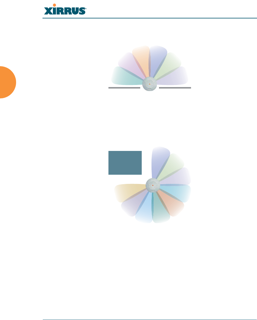
Wi-Fi Array
64 Installing the Wi-Fi Array
service into public areas. The same principle applies if you want to restrict service
to an adjacent room within the site.
Figure 13. Adjusting RF Patterns
Custom Coverage
Where there are highly reflective objects in proximity to the Array, you can turn
off specific radios to avoid interference and feedback.
Figure 14. Custom Coverage
outside wall
object
reflective
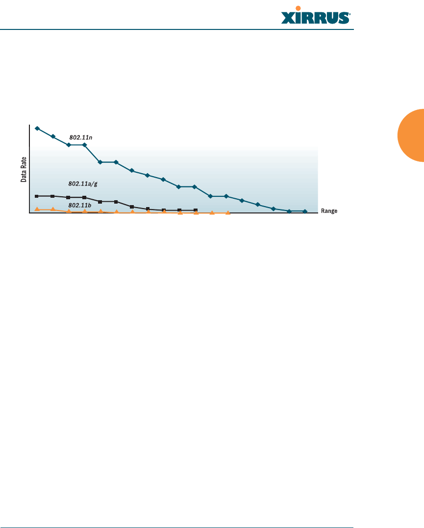
Wi-Fi Array
Installing the Wi-Fi Array 65
Capacity and Cell Sizes
Cell sizes should be estimated based on the number of users, the applications
being used (for example, data/video/voice), and the number of Arrays available
at the location. The capacity of a cell is defined as the minimum data rate desired
for each sector multiplied by the total number of sectors being used.
Figure 15. Connection Rate vs. Distance
Figure 15 shows relative connection rates for 802.11n vs. 802.11a/g and 802.11b,
and the effect of distance on the connection rates. Wireless environments can vary
greatly so the actual rates may be different depending on the specific network
deployment.
The XS4 and XN4 have a smaller range than the larger Arrays.

Wi-Fi Array
66 Installing the Wi-Fi Array
Fine Tuning Cell Sizes
Adjusting the transmit power allows you to fine tune cell sizes. There are four
standard sizes — Small, Medium, Large, or Max (the default is Max). There is also
an Auto setting that automatically determines the best cell size, and a Manual
setting that allows you to choose your power settings directly.
Figure 16. Transmit Power
Auto Cell Size is an automatic, self-tuning mechanism that balances cell size
between Arrays to guarantee coverage while limiting the RF energy that could
extend beyond the organizational boundary. Auto Cell uses communication
between Arrays to dynamically set radio power so that complete coverage is
provided to all areas, yet at the minimum power level required. This helps to
minimize potential interference with neighboring networks. Additionally, Arrays
running Auto Cell automatically detect and compensate for coverage gaps caused
by system interruptions. To enable the Auto Cell Size feature, go to “RF Power &
Sensitivity” on page 298. For a complete discussion of the Auto Cell size feature,
see the Xirrus Auto Cell Application Note in the Xirrus Library.
If you are installing many units in proximity to each other, we recommend that
you use Auto Cell Size; otherwise, reduce the transmit power using manual
settings to avoid excessive interference with other Arrays or installed APs. See
also, “Coverage and Capacity Planning” on page 62.
Large
Medium
Small

Wi-Fi Array
Installing the Wi-Fi Array 67
Sharp Cell
This patented Xirrus RF management option automatically creates more
intelligently defined cells and improves performance by creating smaller, high-
throughput cells. By dynamically limiting each cell to a defined boundary (cell
size), the trailing edge bleed of RF energy is reduced, thus minimizing
interference between neighboring Wi-Fi Arrays or other Access Points. To enable
the Sharp Cell feature, go to “RF Power & Sensitivity” on page 298. For more
information about this feature, see the Xirrus Sharp Cell Application Note in the
Xirrus Library.
Roaming Considerations
Cells should overlap approximately 10 - 15% to accommodate client roaming.
Figure 17. Overlapping Cells
Allocating Channels
Because the Wi-Fi Array is a multi-channel device, allocating the best channels to
radios is important if peak performance is to be maintained.
Automatic Channel Selection
We recommend that you allow the Array to make intelligent channel allocation
decisions automatically. In the automatic mode, channels are allocated
dynamically, driven by changes in the environment. Auto Channel assignment is
ROAMING
10 - 15% overlap

Wi-Fi Array
68 Installing the Wi-Fi Array
performed by scanning the surrounding area for RF activity on all channels, then
automatically selecting and setting channels on the Array to the best channels
available. This function is typically executed when initially installing Arrays in a
new location and may optionally be configured to execute periodically to account
for changes in the RF environment over time. Auto Channel selection has
significant advantages, including:
Allows the Array to come up for the first time and not interfere with
existing equipment that may be already running, thereby limiting co-
channel interference.
More accurately tunes the RF characteristics of a Wi-Fi installation than
manual configuration since the radios themselves are scanning the
environment from their physical location.
May be configured to run periodically.
To set up the automatic channel selection feature, go to “Advanced RF Settings”
on page 294. For more information about this feature, see the Xirrus Auto Channel
Application Note in the Xirrus Library.

Wi-Fi Array
Installing the Wi-Fi Array 69
Manual Channel Selection
You can manually assign channels on a per radio basis, though manual selection
is not recommended (and not necessary).
Figure 18. Allocating Channels Manually
See Also
Deployment Examples
Failover Planning
Installation Prerequisites
To avoid co-channel interference, do not select adjacent channels for radios
that are physically next to each other.
Maintain channel separation
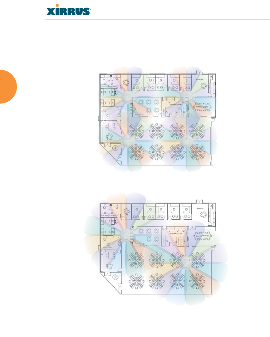
Wi-Fi Array
70 Installing the Wi-Fi Array
Deployment Examples
The following examples employ 802.11a cells, each offering minimum
throughputs of 54 Mbps, 36 Mbps, and 18 Mbps per sector respectively, and
assume a floor plan covering a total area of about 60,000 square feet (5574 sq m).
Figure 19. Deployment Scenario (54 Mbps) — Per Sector
Figure 20. Deployment Scenario (36 Mbps) — Per Sector
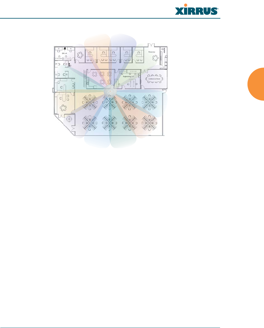
Wi-Fi Array
Installing the Wi-Fi Array 71
Figure 21. Deployment Scenario (18 Mbps) — Per Sector
See Also
Coverage and Capacity Planning
Failover Planning
Planning Your Installation

Wi-Fi Array
72 Installing the Wi-Fi Array
IEEE 802.11n Deployment Considerations
The Xirrus XR and XN Arrays support IEEE 802.11n on all IAPs, in both 2.4 GHz
and 5 GHz bands. Use of 802.11n offers significant benefits:
Higher data rates
Higher throughput
Supports more users
More robust connections
Increased coverage area
More secure connections — supports WPA2 (Wi-Fi Protected Access 2)
These benefits result in better support for a wide range of applications such as
voice and video, intensive usage such as CAD/CAM and backups, dense user
environments, and for manufacturing and warehousing environments.
The techniques that 802.11n uses to realize these performance improvements, and
the results that can be expected are discussed in:
“MIMO (Multiple-In Multiple-Out)” on page 73
“Multiple Data Streams — Spatial Multiplexing” on page 75
“Channel Bonding” on page 76
“Improved MAC Throughput” on page 77
“Short Guard Interval” on page 77
“Obtaining Higher Data Rates” on page 78
“802.11n Capacity” on page 79
IEEE 802.11n features are supported only on XR and XN Array models, and
this section applies only to those Arrays. Note that the license installed on
the Array must include support for 802.11n. Please see “About Licensing
and Upgrades” on page 325.
While 802.11n increases coverage area by almost doubling the reach, you
must consider the legacy wireless devices in your network. Wireless stations
connecting using 802.11a/b/g will still be subject to a reach of up to 100 feet,
depending on the environment.
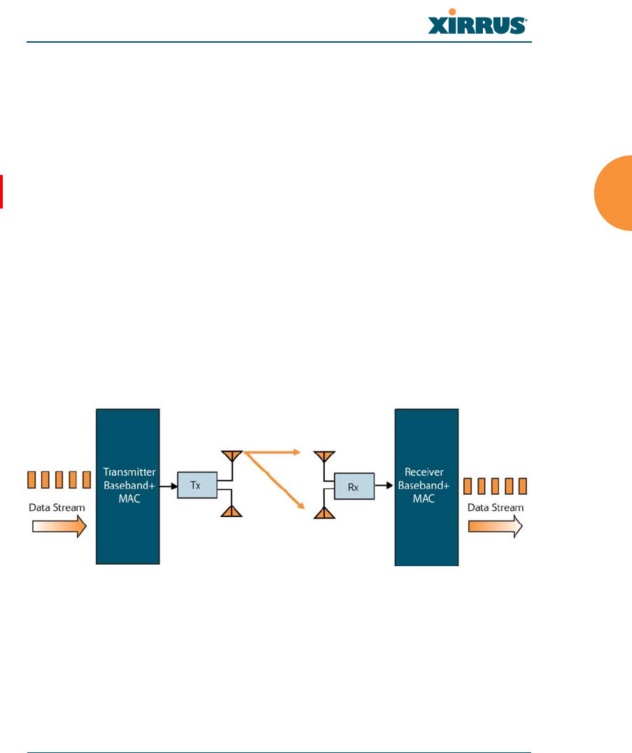
Wi-Fi Array
Installing the Wi-Fi Array 73
Two very important techniques to consider are Channel Bonding and Multiple
Data Streams — Spatial Multiplexing because they contribute a large portion of
802.11n’s speed improvements and because they are optional and configurable, as
opposed to the parts of 802.11n that are fixed. While the settings for 802.11n IAPs
come pre-configured on the Array for robust performance in typical usage, you
should review the settings for your deployment, especially channel bonding. A
global setting is provided to enable or disable 802.11n mode. See “Global Settings
.11n” on page 291 to configure 802.11n operation.
MIMO (Multiple-In Multiple-Out)
MIMO (Multiple-In Multiple-Out) signal processing is one of the core
technologies of 802.11n. It mitigates interference and maintains broadband
performance even with weak signals.
Prior to 802.11n, a data stream was transmitted via one antenna. At the receiving
end, the antenna with the best signal was selected to receive data. (Figure 22)
Figure 22. Classic 802.11 Signal Transmission
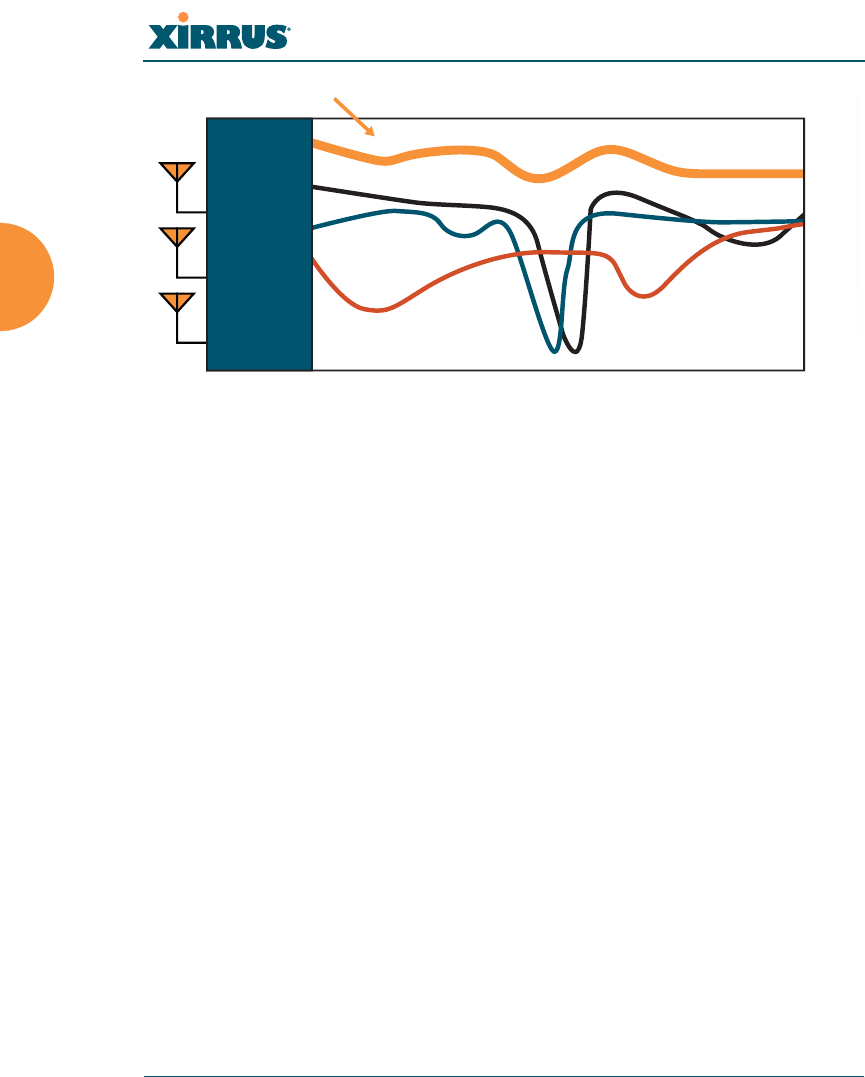
Wi-Fi Array
74 Installing the Wi-Fi Array
Figure 23. MIMO Signal Processing
MIMO signal processing uses multiple antennas to send and receive data. It takes
advantage of multipath reflections to improve signal coherence and greatly
increase receiver sensitivity (Figure 23). Multipath signals were considered to be
interference by 802.11a/b/g radios, and degraded performance. In 802.11n, these
signals are used to enhance performance. This extra sensitivity can be used for
greater range or higher data rates. The enhanced signal is the processed sum of
individual antennas. Signal processing eliminates nulls and fading that any one
antenna would see. MIMO signal processing is sophisticated enough to discern
multiple spatial streams (see Multiple Data Streams — Spatial Multiplexing).
There are no settings to configure for MIMO.
Frequency Across Subcarriers
Attenuation
Antenna 1 Signal
MIMO Processed Signal
Antenna 2 Signal
Antenna 3 Signal
Receiver
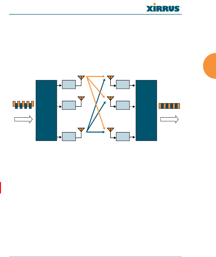
Wi-Fi Array
Installing the Wi-Fi Array 75
Multiple Data Streams — Spatial Multiplexing
Spatial Multiplexing transmits completely separate data streams on different
antennas (in the same channel) that are recombined to produce new 802.11n data
rates. Higher data rates are achieved by splitting the original data stream into
separate data streams. Each separate stream is transmitted on a different antenna
(using its own RF chain). MIMO signal processing at the receiver can detect and
recover each stream. Streams are then recombined, yielding higher data rates.
Figure 24. Spatial Multiplexing
Spatial multiplexing can double, triple, or quadruple the date rate, depending on
the number of transmit antennas used. You can configure the number of chains
(i.e., streams) separately for transmitting and receiving. By default, the Array uses
three chains for transmitting and receiving (see “Global Settings .11n” on
page 291).
%
Rx 1
Rx 2
Rx
M
%
Transmitter
Data Stream Data Stream
Receiver
Tx 1
Tx 2
Tx
N
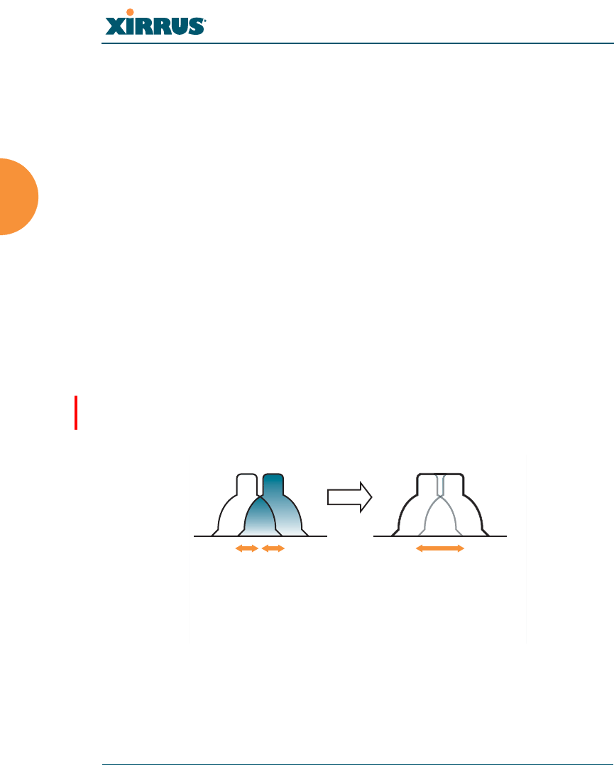
Wi-Fi Array
76 Installing the Wi-Fi Array
Channel Bonding
Channel bonding increases data rates by combining two adjacent 20 MHz
channels into one 40 MHz channel. This increases the data rate to slightly more
than double.
A bonded 40 MHz channel is specified in terms of the Primary channel and the
adjacent channel to Bond. The Bond channel is represented by +1 to use the
channel above the Primary channel, or -1 to use the channel below. In the example
shown, Channel 40 is the Primary channel and it is bonded to Channel 36, the
channel below it, by specifying -1. Be aware that Channel Bonding can make
channel planning more difficult, since you are using two channels for an IAP. We
recommend the use of the 5 GHz band, since it has many more channels than the
2.4 GHz band, and thus more channels are available for bonding.
The Array provides an Automatic Channel Bonding setting that will
automatically select the best channel for bonding on each IAP. If you enable this
option, you may select whether bonding will be dynamic (the bonded channel
changes in response to environmental conditions) or static (the bonded channel
will not be changed. See “Global Settings .11n” on page 291. To configure channel
bonding manually, on a per-IAP basis, see “IAP Settings” on page 271.
Figure 25. Channel Bonding
Ch# Ch#
40
20 MHz 20 MHz
36
40 MHz
(40, -1)
Standard 802.11 channels are
effectively 20MHz wide.
Channel bonding combines
two adjacent 20MHz channels
into a single 40MHz channel
providing increased throughput.
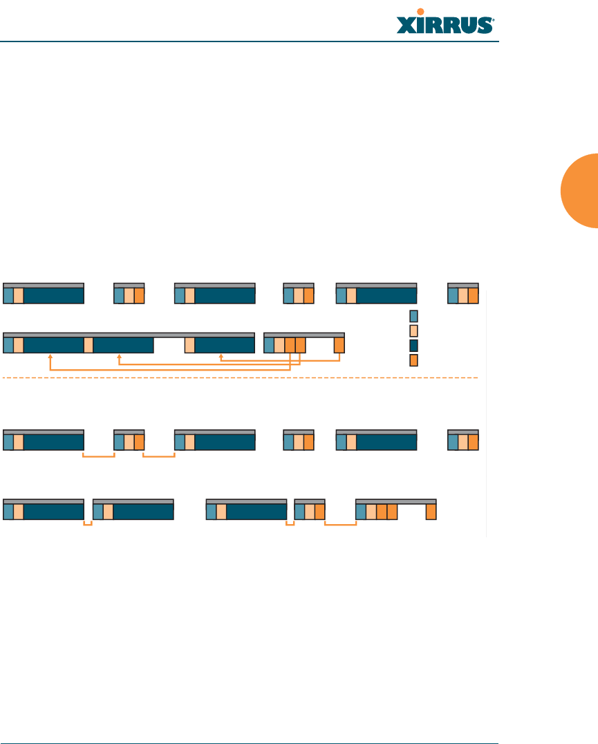
Wi-Fi Array
Installing the Wi-Fi Array 77
Improved MAC Throughput
These changes make 802.11n transmission of MAC frames 40% more efficient than
legacy transmission:
MAC data frames are combined and given a single PHY header.
Implicit Block ACK acknowledges all data frames within a combined
frame.
Spacing between frames is reduced.
Figure 26. MAC Throughput Improvements
Short Guard Interval
This option reduces the wait time between signals that are being sent out over the
air. The guard interval provides immunity to propagation delays and reflections,
and is normally 800 ns (long). By using a short guard interval (400 ns), the data
rate is increased by approximately 11%. The short interval may be used in many
environments (especially indoors). If the short guard interval is used in an
N
ACK Frame
N
Data Frame
2
Data Frame
PHY Header
MAC Header
Data Frame Payload
ACK Frame Payload
Legacy Operation
High Throughput Operation
Data Frame
sss
sss sss
1
Data Frame Block ACK Frame
1122NN
ACK Frame
1 2
ACK Frame
NN
Data Frame
SIFS
SIFS
SIFS
RIFS RIFS
Legacy Operation
High Throughput Operation
Data Frame ACK Frame
sss
ssssss
1
1 2
Data Frame Data Frame Data Frame
Block ACK
Request
Frame
Block ACK
Response
Frame
12 N
1 2 2
2
Data Frame ACK Frame
N
ACK Frame
RIFS Usage (Reduced Inter-Frame Spacing)
Frame Aggregation
Wi-Fi Array
78 Installing the Wi-Fi Array
inappropriate environment, the signal quality will suffer and throughput will
decrease. See “Global Settings .11n” on page 291 to configure the guard interval.
Obtaining Higher Data Rates
The data rate increase obtained by using 802.11n on an Array is incremental,
based on the technologies that are applied and the options that you select:
Higher encoding rates (Mandatory in 802.11n)
Spatial Streams (Mandatory, but multiplier varies directly with number of
streams selected.)
Channel Bonding (Mandatory in 802.11n, apply multiplier to IAP if it is
bonded.)
Short Guard Interval (Optional)
See Figure 27 to compute your 802.11n data rate increase for an IAP. Apply this
increase to the 802.11 a, b or g data rates selected for the Array.
Figure 27. Computing 802.11n Data Rates
Optionally
Multiply By 2.077
to Bond
Two 20MHz
Channels
Optionally
Multiply by 1.11 for
Shorter Guard Interval
to Increase
Symbol Rate
Optionally
Multiply by 2, 3, 4
for the Number of
Additional
Spatial Streams
Choose New Base
Encoding + Modulation
BPSK (6.5)
QPSK (13, 19.5)
QAM-16 (26, 39)
QAM-64 (58.5, 65)
New 11n
Data Rate
xxx =
Expected First Generation Device Data Rates
Expected 802.11n Data Rates
802.11a 802.11g
Rates
6
9
12
18
24
36
48
54
11n Mandatory
Data Rates
6.5
13
19.5
26
39
52
58.5
65
With Channel
Bonding (40MHz)
13.5
27
40.5
54
81
108
121.5
135
With Short
Guard Interval
15
30
45
60
90
120
135
150
Two Spatial
Streams
13
26
39
52
78
104
117
130
With Channel
Bonding (40MHz)
27
54
81
108
162
216
243
270
With Short
Guard Interval
30
60
90
120
180
240
270
300
One Spatial Stream Two Spatial Streams
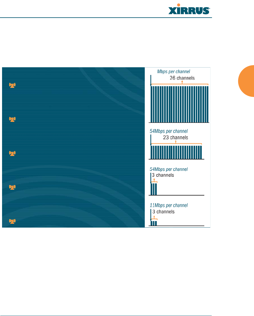
Wi-Fi Array
Installing the Wi-Fi Array 79
802.11n Capacity
802.11n offers major increases in capacity over previous 802.11 standards, as
shown in Figure 28. Note that this chart shows figures for 802.11n (with one
spatial stream and channel bonding).
Figure 28. 802.11n Increases Capacity
802.11a/n Capacity
23 channels * 150Mbps = 3.4Gbps
802.11a Capacity
23 channels * 54Mbps = 1.2 Gbps
802.11g/n Capacity
3 channels * 150Mbps = 450 Mbps
802.11g Capacity
3 channels * 54Mbps = 162 Mbps
802.11b Capacity
3 channels * 11Mbps = 33 Mbps
802.11a/n Capacity
23 channels * 150Mbps = 3.4Gbps
802.11a Capacity
23 channels * 54Mbps = 1.2 Gbps
802.11g/n Capacity
3 channels * 150Mbps = 450 Mbps
802.11g Capacity
3 channels * 54Mbps = 162 Mbps
802.11b Capacity
3 channels * 11Mbps = 33 Mbps
150
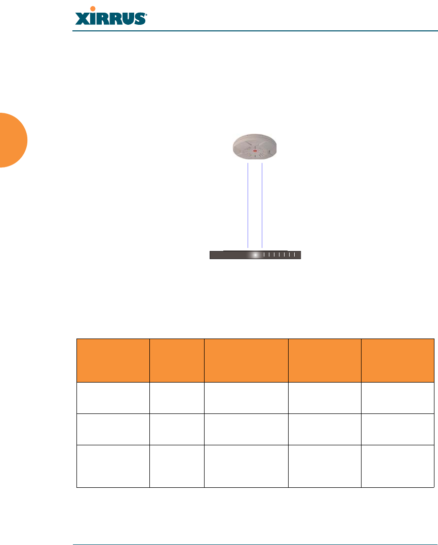
Wi-Fi Array
80 Installing the Wi-Fi Array
Failover Planning
This section discusses failover protection at the unit and port levels.
Port Failover Protection
To ensure that service is continued in the event of a port failure, you can utilize
the Gigabit 1 and Gigabit 2 ports simultaneously.
Figure 29. Port Failover Protection
In addition, the Array has full failover protection between the Gigabit 1 and
Gigabit 2 Ethernet ports (see following table).
The Wi-Fi Array Gigabit Ethernet ports actually support a number of modes:
802.3ad Link Aggregation
Interface Bridges
Data?
Bridges
Management
Traffic?
Fails Over To: IP address
Fast Ethernet No Yes None DHCP or
static
Gigabit 1 Yes Yes Gigabit 2 DHCP or
static
Gigabit 2 Yes Yes Gigabit 1 Assumes the
IP address of
Gigabit 1
Ethernet switch
Multiple port connections
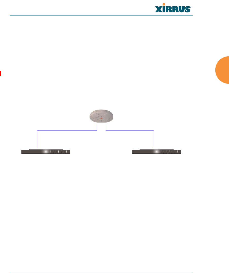
Wi-Fi Array
Installing the Wi-Fi Array 81
Load Balancing
Broadcast
Link Backup
Bridged
Mirrored
For more details on Gigabit port modes and their configuration, please see
“Network Interface Ports” on page 181.
Switch Failover Protection
To ensure that service is continued in the event of a switch failure, you can
connect Arrays to more than one Ethernet switch (not a hub).
Figure 30. Switch Failover Protection
See Also
Coverage and Capacity Planning
Deployment Examples
Installation Prerequisites
Network Management Planning
Planning Your Installation
Power Planning
Security Planning
Gigabit Ethernet connections must be on the same subnet.
Ethernet switch Backup switch
Ethernet connections

Wi-Fi Array
82 Installing the Wi-Fi Array
Power Planning
All XR and XN Series Array models and XS16/8/4 Arrays support Power over
Gigabit Ethernet (PoGE) with an integrated splitter. AC power is also supported
on some versions of the XS8 and XS16.? True??
This section discusses the AC and PoGE power options.
AC Power
The AC power option requires a direct connection between the Array and a
dedicated AC power outlet. The power cord is provided with the unit.
Power over Gigabit Ethernet
To deliver power to the Array, you may use the optional XP1, XP2, or XP8 Power
over Gigabit Ethernet (PoGE) modules. They provide power over Cat 5e or Cat 6
cables to the Array without running power cables — see Figure 5 on page 14.
Specific models of the Array are compatible with specific PoGE modules. For
details, please see “Power over Gigabit Ethernet Compatibility Matrix” on
page 451.
See Also
Coverage and Capacity Planning
Deployment Examples
Failover Planning
Network Management Planning
Security Planning
When using Cat 5e or Cat 6 cable, power can be provided up to a distance of
100m.

Wi-Fi Array
Installing the Wi-Fi Array 83
Security Planning
This section offers some useful guidelines for defining your preferred encryption
and authentication method. For additional information, see “Understanding
Security” on page 210 and the Security section of “Frequently Asked Questions”
on page 432.
Wireless Encryption
Encryption ensures that no user can decipher another user’s data transmitted
over the airwaves. There are three encryption options available to you, including:
WEP-40bit or WEP-128bit
Because WEP is vulnerable to cracks, we recommend that you only use
this for legacy devices that cannot support a stronger encryption type.
Wi-Fi Protected Access (WPA)
This is much more secure than WEP and uses TKIP for encryption.
Wi-Fi Protected Access (WPA2) with AES
This is government-grade encryption — available on most new client
adapters — and uses the AES–CCM encryption mode (Advanced
Encryption Standard–Counter Mode).
Authentication
Authentication ensures users are who they say they are, and occurs when users
attempt to join the wireless network and periodically thereafter. The following
authentication methods are available with the Wi-Fi Array:
RADIUS 802.1x
802.1x uses a remote RADIUS server to authenticate large numbers of
clients, and can handle different authentication methods (EAP-TLS, EAP-
TTLS, EAP-PEAP, and EAP-LEAP Passthrough). Administrators may
Note that several advanced features in this section are part of the Xirrus
Advanced RF Security Manager (RSM). They require the license installed
on the Array to include support for RSM. Please see “About Licensing and
Upgrades” on page 325.

Wi-Fi Array
84 Installing the Wi-Fi Array
also be authenticated via RADIUS when preferred, or to meet particular
security standards.
Xirrus Internal RADIUS server
Recommended for smaller numbers of users (about 100 or less). Supports
EAP-PEAP only
Pre-Shared Key
Uses a pass-phrase or key that is manually distributed to all authorized
users. The same passphrase is given to client devices and entered into
each Array.
MAC Access Control Lists (ACLs)
MAC access control lists provide a list of client adapter MAC addresses
that are allowed or denied access to the wireless network, and can be
used in addition to any of the above authentication methods. ACLs are
good for embedded devices, like printers and bar-code scanners (though
MAC addresses can be spoofed). The Array supports 1,000 ACL entries.
Meeting PCI DSS Standards
The Payment Card Industry (PCI) Data Security Standard (DSS) was developed
by major credit card companies. It lays out a set of requirements that must be met
in order to provide adequate security for sensitive data. The Wi-Fi Array may be
configured to satisfy PCI DSS standards. For details, please see Appendix D:
Implementing PCI DSS. Note that the license installed on the Array must include
the Xirrus Advanced RF Security Manager (RSM) to support PCI audit
compliance enforcement. Please see “About Licensing and Upgrades” on
page 325.
Meeting FIPS Standards
The Federal Information Processing Standard (FIPS) Publication 140-2 establishes
a computer security standard used to accredit cryptographic modules. The
standard is a joint effort by the U.S. and Canadian governments. To implement
Level 2 security requirements of FIPS Level 2 on the Wi-Fi Array, see Appendix E:
Implementing FIPS Security.

Wi-Fi Array
Installing the Wi-Fi Array 85
See Also
Failover Planning
Network Management Planning
Power Planning
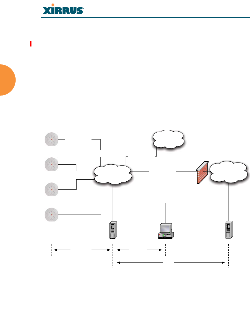
Wi-Fi Array
86 Installing the Wi-Fi Array
Port Requirements
A number of ports are used by various Array features and by the Xirrus
Management System (XMS). The Port Requirements table on page 87 lists ports
and the features that require them (XMS port requirements are included in the
table for your convenience). If you are using a feature, please make sure that the
ports that it requires are not blocked by firewalls or other policies, and that they
do not conflict with any other port assignments.
As an example, XMS port requirements are illustrated in Figure 31. XMS requires
ports 161, 162, and 443 to be passed between Arrays and the XMS server.
Similarly, ports 9090 and 9091 are required for communication between the XMS
server and XMS clients, and port 25 is typically used by the XMS server to access
an SMTP server to send email notifications.
Figure 31. Port Requirements for XMS
Firewall
XMS Server XMS Client*
L2 Switching
Infrastructure
SMTP Server*
Internal
Resources
External Network /
Internet
Ports:
9090, 9091
Ports:
161, 162, 443
SSID Traffic on
VLANs A, B, etc.
Management over
Native VLAN
Traffic from Arrays
VLAN B
Traffic from Arrays
VLAN A
Trunked 802.1q
VLAN Connection
Ports:
25
* XMS Client and SMTP Server may be internal or external resources.

Wi-Fi Array
Installing the Wi-Fi Array 87
The following table lists port requirements for the Array and for XMS, how they
are used, and whether they may be changed.
Port Application Peer Configurable
Array
20 tcp
21 udp FTP Client Yes
22 tcp SSH Client Yes
23 tcp Telnet Client Yes
25 tcp SMTP Mail Server No
69 tcp TFTP TFTP Server No
161 tcp/udp SNMP XMS Server No
162 tcp/udp
SNMP Traphost Note -
Up to four Traphosts
may be configured.
XMS Server
Yes - but
required by
XMS
443 tcp HTTPS (WMI,WPR) Client Yes
514 udp Syslog Syslog Server No
1812, 1645
udp
RADIUS (some
servers use 1645) RADIUS Server Yes
1813, 1646
udp
RADIUS Accounting
(some servers still use
1646)
RADIUS Accounting
Server Yes
2055 udp Netflow Client Yes
5000 tcp Virtual Tunnel VTUN Server Yes

Wi-Fi Array
88 Installing the Wi-Fi Array
See Also
Management Control
External Radius
Services
VLAN Management
XMS
25 tcp SMTP Mail Server Yes
161 udp SNMP Arrays No
162 udp SNMP Traphost 1 Arrays Via XMS
config file
443 tcp HTTPS Arrays No
514 udp Resident Syslog
server Internal* Via XMS
config file
1099 tcp RMI Registry Internal* No
2000 tcp XMS Back-end Server Internal* No
3306 tcp MySQL Database Internal* No
8001 tcp Status Viewer Internal* No
8007 tcp Tomcat Shutdown Internal* During
installation
8009 tcp Web Container Internal* During
installation
9090 tcp XMS Webserver XMS client During
installation
9091 tcp XMS Client Server XMS client Via XMS
config file
* Internal to XMS Server, no ports need to be unblocked on other network devices
Port Application Peer Configurable

Wi-Fi Array
Installing the Wi-Fi Array 89
Network Management Planning
Network management can be performed using any of the following methods:
Command Line Interface, using an SSH (Secure Shell) utility, like PuTTY.
The utility must be set up to use SSH-2, since the Array will only allow
SSH-2 connections.
Web-based management, using the Array’s embedded Web Management
Interface (WMI). This method provides configuration and basic
monitoring tools, and is good for small deployments (one or two units).
Centralized Web-based management, using the optional Xirrus
Management System (XMS), which can be run on a dedicated Xirrus
appliance (XM-3300) or your own server. The XMS is used for managing
large Wi-Fi Array deployments from a centralized Web-based interface
and offers the following features:
Globally manage large numbers of Arrays (up to 500)
Seamless view of the entire wireless network
Easily configure large numbers of Arrays
Rogue AP monitoring
Easily manage system-wide firmware updates
Monitor performance and trends
Aggregation of alerts and alarms
See Also
Failover Planning
Power Planning
Security Planning
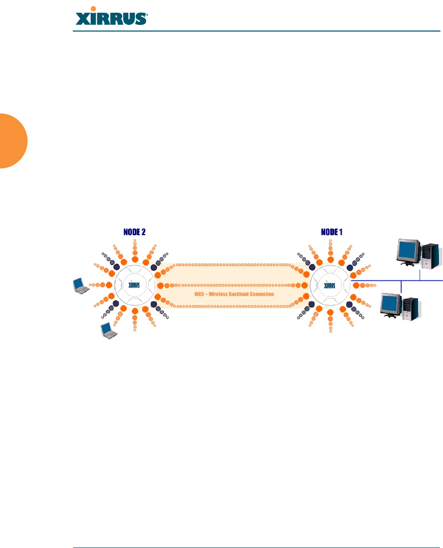
Wi-Fi Array
90 Installing the Wi-Fi Array
WDS Planning
WDS (Wireless Distribution System) creates wireless backhauls between arrays,
allowing your wireless network to be expanded using multiple Arrays without
the need for a wired backbone to link them (see Figure 32). WDS features include:
One to three IAPs may be used to form a single WDS link, yielding up to
900 Mbps bandwidth per link (up to 162 Mbps for XS model Arrays). Up
to three different WDS links may be created on a single Array.
Automatic IAP Load Balancing
If desired, you may allow clients to associate to a BSS on the same radio
interface used for a WDS Host Link. This will take bandwidth from the
WDS link.
Figure 32. WDS Link
Multiple links per Array allow you to configure multi-hop connections.
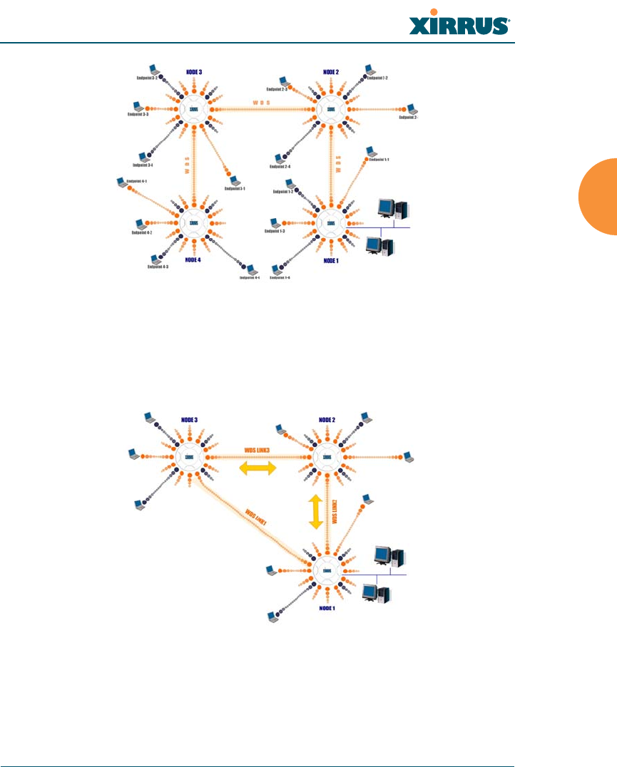
Wi-Fi Array
Installing the Wi-Fi Array 91
Figure 33. A Multiple Hop WDS Connection
Multiple WDS links can provide link redundancy (failover capability - see
Figure 34). A network protocol (Spanning Tree Protocol — STP) prevents
Arrays from forming network loops.
Figure 34. WDS Failover Protection

Wi-Fi Array
92 Installing the Wi-Fi Array
WDS links have a Host/Client relationship similar to the usual IAP/station
pattern for Arrays:
A WDS Client Link associates/authenticates to a host (target) Array in the
same way that a station associates to an IAP. The client side of the link
must be configured with the root MAC address of the target (host) Array.
A WDS Host Link acts like an IAP by allowing one WDS Client Link to
associate to it. An Array may have both client and host links.
WDS configuration is performed only on the client-side Array. See “WDS” on
page 305. Note that both Arrays must be configured with the same SSID name.

Wi-Fi Array
Installing the Wi-Fi Array 93
Common Deployment Options
The following table lists some typical and recommended deployment options for
a number of the features that have been discussed in this chapter.
See Also
Coverage and Capacity Planning
Deployment Examples
Network Management Planning
Planning Your Installation
Power Planning
Security Planning
Function
Number of Wi-Fi Arrays
One or Two Three or More
Power AC (some Array models)
Power over Gigabit
Ethernet
AC (some Array models)
Power over Gigabit Ethernet
UPS backup
(recommended)
Failover Recommended Highly recommended
VLANs Optional Optional use,
Can be used to put all APs
on one VLAN or map to
existing VLAN scheme
Encryption WPA2 with AES
(recommended)
PSK or 802.1x
WPA2 with AES
(recommended)
802.1x keying
Authentication Internal RADIUS server
EAP-PEAP
Pre-Shared Key
External RADIUS server
Management Internal WMI
Internal CLI (via SSHv2)
XMS (SNMP)
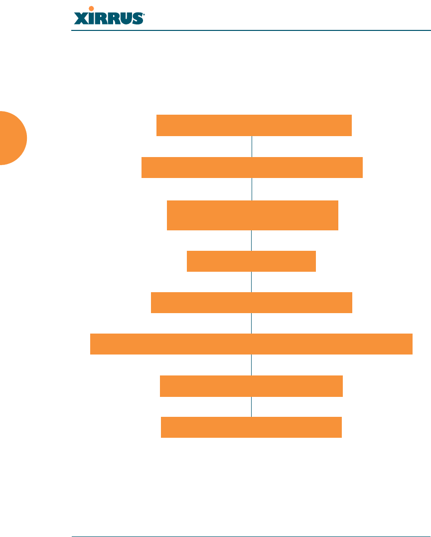
Wi-Fi Array
94 Installing the Wi-Fi Array
Installation Workflow
This workflow illustrates the steps that are required to install and configure your
Wi-Fi Array successfully. Review this flowchart before attempting to install the
unit on a customer’s network.
Figure 35. Installation Workflow
See Also
Coverage and Capacity Planning
Deployment Examples
Determine the number of Arrays needed
Choose the location(s) for your Wi-Fi Arrays
Install the mounting plate
Connect the cables and turn on the power
Verify that the Ethernet link and radio LEDs are functioning correctly
Perform the Express Setup procedure
Run Ethernet cables for PoGE
(<100m total distance from switch)
Log in to WMI and enter your license

Wi-Fi Array
Installing the Wi-Fi Array 95
Common Deployment Options
Failover Planning
Installation Prerequisites
Planning Your Installation
Power Planning
Wi-Fi Array Product Overview
Product Specifications — XN16, XN12, and XN8
Product Specifications — XS16 and XS8
Product Specifications — XS4
Security Planning
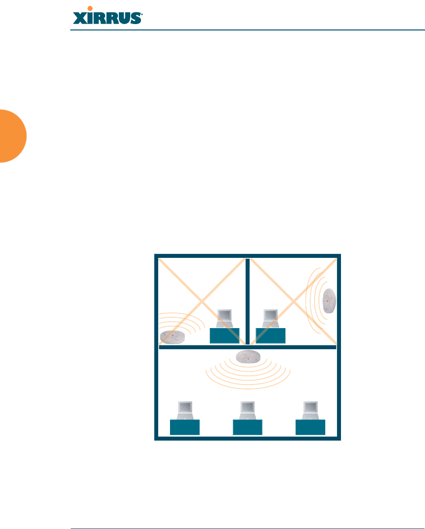
Wi-Fi Array
96 Installing the Wi-Fi Array
Installing Your Wi-Fi Array
This section provides instructions for completing a physical installation of your
Xirrus Wi-Fi Array.
Choosing a Location
Based on coverage, capacity and deployment examples previously discussed,
choose a location for the Array that will provide the best results for your needs.
The Wi-Fi Array was designed to be mounted on a ceiling where the unit is
unobtrusive and wireless transmissions can travel unimpeded throughout open
plan areas.
You also have the option of mounting the Array on a wall, using the optional wall
mount assembly kit.
Choose a location that is central to your users (see the following diagram for
correct placement.
Figure 36. Array Placement
WR
ONG
CORRECT
R
ORRE
R
ORREC
WR
ONG
G
G
O
ON
R
O
R
ON
ON
R
O
R
ON

Wi-Fi Array
Installing the Wi-Fi Array 97
Wiring Considerations
If you are using the Xirrus Power over Gigabit Ethernet modules (PoGE) to
distribute power, see “Power over Gigabit Ethernet (PoGE)” on page 14. If you
prefer to use AC power and you have an Array that supports AC, an AC power
outlet must be available to the Array.
Once you have determined the best location for your Wi-Fi Array, you must run
cables to the location for the following services:
Power
One of the following options:
No power cable to the Array is required if using PoGE modules.
The PoGE module requires a dedicated AC power outlet (100 -
240 VAC).
Dedicated AC power if PoGE is not in use. A UL-approved cord
is shipped with all AC-equipped Arrays. You must use a UL-
approved cord if using AC power.
Network
Gigabit 1 — If using PoGE modules, the total of all Cat 5e or Cat 6
cable segments from the Gigabit Ethernet switch to the Array
must be less than 100m long. The Array must be connected to
PoGE networks without routing cabling to the outside plant, to
ensure that cabling is not exposed to lightning strikes or possible
high voltage crossover.
Gigabit 2 (optional, not available on the four-port Arrays)
Fast Ethernet (optional, not available on the four-port Arrays)
Serial cable (optional) — cable lengths up to 25’ per the RS-232
specification.

Wi-Fi Array
98 Installing the Wi-Fi Array
Important Notes About Network Connections
Read the following notes before making any network connections.
See Also
Failover Planning
Installation Prerequisites
Installation Workflow
Mounting the Array
Power over Gigabit Ethernet (PoGE)
When the unit’s IP address is unknown or a network connection has not
been established, the serial cable is used for connecting directly with the
Command Line Interface (CLI) via HyperTerminal. When a network
connection is established, the Array can be managed from any of the
available network connections, either Fast Ethernet, Gigabit 1 or Gigabit 2.
!The Array’s Ethernet ports should be plugged into an Ethernet switch, not an
Ethernet hub — if a hub is used, we recommend that you connect only one
Ethernet port.
!The Gigabit1 Ethernet interface is the primary port for both data and
management traffic. If a single Ethernet connection is used, it must be
connected to the Gigabit1 Ethernet interface. See also, “Port Failover
Protection” on page 80.
The 10/100 Ethernet Port may be used for managing the Array out of band
from the Gigabit Ethernet ports. The 10/100 port will route only management
traffic, using a static route that may be configured for this interface. See
“interface” on page 370.

Wi-Fi Array
Installing the Wi-Fi Array 99
Mounting the Array
A number of options are available for mounting Arrays:
Ceiling mount
Wall mount
Secure mount in a locking indoor enclosure
Outdoor enclosure
I-Beam mount in a protective enclosure (gymnasium mount)
Factory enclosure
A detailed Quick Installation Guide is provided with the mounting option that
you selected when ordering your Array. Please follow the provided instructions
carefully.
Dismounting the Array
To dismount any other Array model
For all Array models other than the XS-3700/3900, push up on the Array (i.e.,
push it against the mounting plate). Then turn the Array to the left to remove it.
This is similar to dismounting a smoke detector.
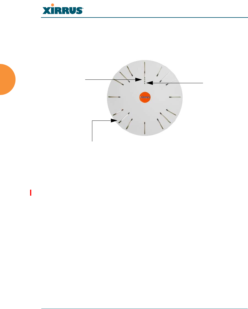
Wi-Fi Array
100 Installing the Wi-Fi Array
Powering Up the Wi-Fi Array
When powering up, the Array follows a specific sequence of LED patterns
showing the boot progress, and following a successful boot will provide extensive
status information.
Figure 37. LED Locations (XN16)
Array LED settings may be altered or disabled entirely for diagnostic purposes or
for personal preference. Changes are made via the Array’s Command Line
Interface or the Web Management Interface — refer to “LED Settings” on page 303.
Status LED
Ethernet Activity
LEDs
IAP LEDs (x16)

Wi-Fi Array
Installing the Wi-Fi Array 101
Array LED Operating Sequences
Use the following tables to review the operating sequences of the Array’s LEDs.
“LED Boot Sequence” on page 101
“LED Operation when Array is Running” on page 102
LED Boot Sequence
The normal boot LED sequence is as follows:
Array Activity Status LED IAP LEDs
Power ON Blinking GREEN All OFF
Boot loader power ON
self-test
Blinking GREEN All ON
Image load from
compact FLASH
Blinking GREEN Spinning pattern (rotate all
to ON, then all to OFF)
Image load failure Blinking ORANGE All OFF
Hand off to ArrayOS Solid GREEN All OFF
System software
initialization
Solid GREEN Walking pattern — (LED
rotating one position per
second)
Up and running Solid GREEN ON for IAPs that are up:
OFF for IAPs that are down.
Behavior may be changed
using “LED Settings” on
page 303.

Wi-Fi Array
102 Installing the Wi-Fi Array
LED Operation when Array is Running
The normal LED operation when the Array is running is shown in the table
below. Note that behavior may be modified using “LED Settings” on page 303 or
via the CLI.
See Also
Installation Prerequisites
Installation Workflow
Installing Your Wi-Fi Array
LED Settings
LED Status Reason
IAP LED is OFF IAP is down
IAP LED is solid ON IAP is up, but no associations and
no traffic
IAP LED heartbeat IAP is up, with stations
associated but no traffic
IAP LED flashing
Flashing at 10 Hz
Flashing at 5 Hz
Flashing at 2.5 Hz
IAP is up, passing traffic
Traffic > 1500 packets/sec
Traffic > 150 packets/sec
Traffic > 1 packet/sec
IAP LED is GREEN IAP is operating in the 2.4 GHz
band
IAP LED is ORANGE IAP is operating in the 5 GHz
band
IAP LED flashing ORANGE to
GREEN at 1 Hz
IAP abg(n)2 is in monitor mode
(standard intrude detect)
Ethernet LEDs are dual color
Ethernet LED is ORANGE
Ethernet LED is GREEN
Transferring data at 1 Gbps
Transferring data at 10/100 Mbps
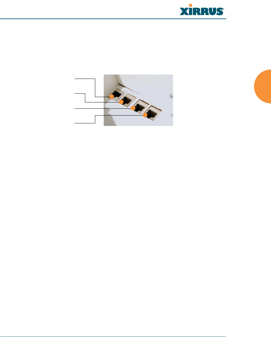
Wi-Fi Array
Installing the Wi-Fi Array 103
Establishing Communication with the Array
The Array can be configured through the Command Line Interface (CLI) or the
graphical Web Management Interface (WMI). You can use the CLI via the serial
management port, the Fast Ethernet port, or either of the Gigabit Ethernet ports.
You can use the WMI via any of the Array’s Ethernet ports.
Figure 38. Network Interface Ports
Using the Serial Port
If using the serial port to make your connection, use serial settings of 8 bits, no
parity, no flow control, 1 stop bit (8N1) and a speed setting of 115200 baud. Use
the communication package of your choice.
Using the Ethernet Ports
By default, the Array's Ethernet interfaces use DHCP to obtain an IP address. If
the Array is booted and does not receive DHCP addresses on either the Fast
Ethernet or Gigabit Ethernet ports, the Fast Ethernet port will default to an IP
address of 10.0.1.1 and both Gigabit Ethernet ports will default to 10.0.2.1. If the
Array is connected to a network that provides DHCP addresses, the IP address
can be determined by the following two methods:
1. Examine the DHCP tables on the server and find the addresses assigned
to the Array (Xirrus MAC addresses begin with 000F7D).
2. Query the Array using the CLI via the serial port. Use the show ethernet
command to view the IP addresses assigned to each port.
Serial
Fast Ethernet
Gigabit 1
Gigabit 2

Wi-Fi Array
104 Installing the Wi-Fi Array
Logging In
When logging in to the Array, use the default user name and password — the
default user name is admin, and the default password is admin.
See Also
Installation Workflow
Performing the Express Setup Procedure
Powering Up the Wi-Fi Array
Entering the License
A license is needed to operate the Wi-Fi Array at full functionality. Without a
license, the Array may only be powered up and have a basic network
configuration.
The Array’s license determines many of the features that are available on the
Array. For example, automatic cell sizing and channel allocation require a license
supporting the RF Performance Manager (RPM). Also, IEEE 802.11n operation on
XR and XN model Arrays requires a license.
The Array’s license is not installed at the factory. You must enter your license
before proceeding to the next step, Performing the Express Setup Procedure.
The procedure below describes entering the license key using the WMI. If you are
using the Xirrus Management System (XMS), you may use it to easily manage and
upgrade large numbers of licenses for the wireless network.
1. This procedure assumes that you have pointed a browser to the Array’s
IP address to start WMI, and that you have logged in with the default
username and password above.
2. In the left had frame, in the Tools section, click System Tools.
3. License Key: Enter the key that was provided for the Array. The key was
provided to you in an email as an attachment in the form of an Excel file
(.xls). Enter the key exactly as it appears in the file. Click the Upgrade
button to apply the key.

Wi-Fi Array
Installing the Wi-Fi Array 105
4. Now you may verify the features provided by the key. In the Status
section of the left hand frame, click Array and then click Information.
Check the items listed in the License Features row.
If you are installing a large number of licenses and do not have XMS, a
Xirrus Licensing Tool may be acquired from Xirrus Support to help push
licenses to large number of Arrays.
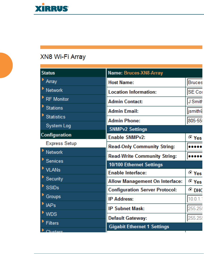
Wi-Fi Array
106 Installing the Wi-Fi Array
Performing the Express Setup Procedure
The Express Setup procedure establishes global configuration settings that enable
basic Array functionality. Changes made in this window will affect all radios.
Figure 39. Express Setup

Wi-Fi Array
Installing the Wi-Fi Array 107
Procedure for Performing an Express Setup
1. Host Name: Specify a unique host name for this Array. The host name is
used to identify the Array on the network. Use a name that will be
meaningful within your network environment, up to 64 alphanumeric
characters. The default is Xirrus-WiFi-Array.
2. Location Information: Enter a brief but meaningful description that
accurately defines the physical location of the Array. In an environment
where multiple units are installed, clear definitions for their locations are
important if you want to identify a specific unit.
3. Admin Contact: Enter the name and contact information of the person
who is responsible for administering the Array at the designated location.
4. Admin Email: Enter the email address of the admin contact you entered
in Step 3.
5. Admin Phone: Enter the telephone number of the admin contact you
entered in Step 3.
6. Configure SNMPv2: Select whether to Enable SNMPv2 on the Array, and
change the SNMP Community Strings if desired. If you are using the
Xirrus Management System (XMS), these strings must match the values
used by XMS. The default values for the Array match the defaults in
XMS. For more details, including SNMPv3, see “SNMP” on page 199.
7. Configure the Fast Ethernet (10/100 Megabit), Gigabit 1 and Gigabit 2
network interfaces. The fields for each of these interfaces are the same,
and include:
a. Enable Interface: Choose Yes to enable this network interface, or
choose No to disable the interface.
b. Allow Management on Interface: Choose Yes to allow management
of the Array via this network interface, or choose No to deny all
management privileges for this interface.
c. Configuration Server Protocol: Choose DHCP to instruct the Array
to use DHCP to assign IP addresses to the Array’s Ethernet interfaces,

Wi-Fi Array
108 Installing the Wi-Fi Array
or choose Static if you intend to enter IP addresses manually. If you
choose the Static IP option, you must enter the following information:
IP Address: Enter a valid IP address for this Array. To use any of
the remote connections (Web, SNMP, or SSH), a valid IP address
must be used.
IP Subnet Mask: Enter a valid IP address for the subnet mask
(the default is 255.255.255.0). The subnet mask defines the
number of IP addresses that are available on the routed subnet
where the Array is located.
Default Gateway: Enter a valid IP address for the default
gateway. This is the IP address of the router that the Array uses
to forward data to other networks.
8. SSID Settings: This section specifies the wireless network name and
security settings.
a. SSID (Wireless Network Name): The SSID (Service Set Identifier) is
a unique name that identifies a wireless network. All devices
attempting to connect to a specific WLAN must use the same SSID.
The default for this field is “xirrus.”
For additional information about SSIDs, go to the Multiple SSIDs
section of “Frequently Asked Questions” on page 432.
b. Wireless Security: Select the desired wireless security scheme (Open,
WEP, WPA, WPA2, or WPA-Both). WPA2 is recommended for the
best Wi-Fi security.
•Open — This option offers no data encryption and is not
recommended, though you might choose this option if clients are
required to use a VPN connection through a secure SSH utility,
like PuTTy.
•WEP (Wired Equivalent Privacy) — An optional IEEE 802.11
function that offers frame transmission privacy similar to a wired
network. WEP generates secret shared encryption keys that both
source and destination stations can use to alter frame bits to
avoid disclosure to eavesdroppers.

Wi-Fi Array
Installing the Wi-Fi Array 109
•WPA (Wi-Fi Protected Access) — A Wi-Fi Alliance standard that
contains a subset of the IEEE 802.11i standard, using TKIP or AES
as an encryption method and 802.1x for authentication.
•WPA2 (Wi-Fi Protected Access 2) — WPA2 is the follow-on
security method to WPA for wireless networks and provides
stronger data protection and network access control. It offers
Enterprise and consumer Wi-Fi users with a high level of
assurance that only authorized users can access their wireless
networks. Like WPA, WPA2 is designed to secure all versions of
802.11 devices, including 802.11a, 802.11b, 802.11g, and 802.11n,
multi-band and multi-mode.
•WPA-Both (WPA and WPA2) — This option makes use of both
WPA and WPA2.
For more information about security, including a full review of all
security options and settings, go to “Understanding Security” on
page 210.
c. Wireless Key/Passphrase: Depending on the wireless security
scheme you selected, enter a unique WEP key or WPA passphrase.
d. Confirm Key/Passphrase: If you entered a WEP key or WPA
passphrase, confirm it here.
9. Admin Settings: This section allows you to change the default password
for the Array. Note that the Array also offers the option of authenticating
administrators using a RADIUS server (see “Admin Management” on
page 215).
a. New Admin Password: If desired, enter a new administration
password for managing this Array. Choose a password that is not
obvious, and one that you can remember. If you forget your
password, you must reset the Array to its factory defaults so that the
password is reset to admin (its default setting).
b. Confirm Admin Password: If you entered a new administration
password, confirm the new password here.

Wi-Fi Array
110 Installing the Wi-Fi Array
10. Time and Date Settings: This section specifies an optional time (NTP -
Network Time Protocol) server or modifies the system time if you’re not
using a server.
a. Time Zone: Select your time zone from the choices available in the
pull-down list.
b. Use Network Time Protocol: Check this box if you want to use an
NTP server to synchronize the Array’s clock. This ensures that Syslog
time-stamping is maintained across all units. Without an NTP server
assigned (no universal clock), each Array will use its own internal
clock and stamp times accordingly, which may result in
discrepancies. If you check Yes, the NTP server fields are displayed. If
you don’t want to use an NTP server, leave this box unchecked
(default) and set the system time on the Array manually.
c. NTP Primary Server: If you are using NTP, enter the IP address or
domain name of the NTP server.
d. NTP Secondary Server: Enter the IP address or domain name of an
optional secondary NTP server to be used in case the Array is unable
to contact the primary server.
e. Set Time (hrs:min:sec): If you are not using NTP, check this box if
you want to adjust the current system time. When the box is checked,
the time fields become active. Enter the revised time (hours, minutes,
seconds, am/pm) in the corresponding fields. If you don’t want to
adjust the current time, this box should be left unchecked (default).
f. Set Date (month/day/year): If you are not using NTP, check this box if
you want to adjust the current system date. When the box is checked,
the date fields become active. Enter the revised date (month, day and
year) in the corresponding fields. If you don’t want to adjust the
current date, this box should be left unchecked (default).
g. Auto Adjust Daylight Savings: If you are not using NTP, check this
box if you want the system to adjust for daylight savings
automatically, otherwise leave this box unchecked (default).
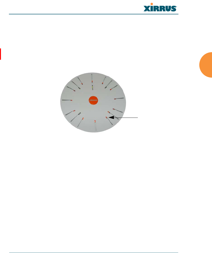
Wi-Fi Array
Installing the Wi-Fi Array 111
11. IAP Settings:
Enable/Configure All IAPs: Click on the Execute button to enable and
auto configure all IAPs (a message displays the countdown time — in
seconds — to complete the auto-configuration task). When an IAP is
enabled, its LED is switched on. (Figure 40, see also “Array LED
Operating Sequences” on page 101.)
Figure 40. LEDs are Switched On
12. Click on the Apply button to apply the new settings to this session
13. Click on the Save button to save your changes (otherwise your new
settings will not take effect).
This ends the Express Setup procedure.
See Also
Establishing Communication with the Array
Installation Prerequisites
Installation Workflow
Logging In
Multiple SSIDs
Security
LED on

Wi-Fi Array
112 Installing the Wi-Fi Array

Wi-Fi Array
The Web Management Interface 113
The Web Management Interface
This topic provides an overview of the Xirrus Wi-Fi Array’s embedded Web
Management Interface (WMI), used for establishing your network’s configuration
settings and wireless operating parameters. It also includes login instructions.
The following topics are discussed:
An Overview
Structure of the WMI
User Interface
Logging In
Applying Configuration Changes
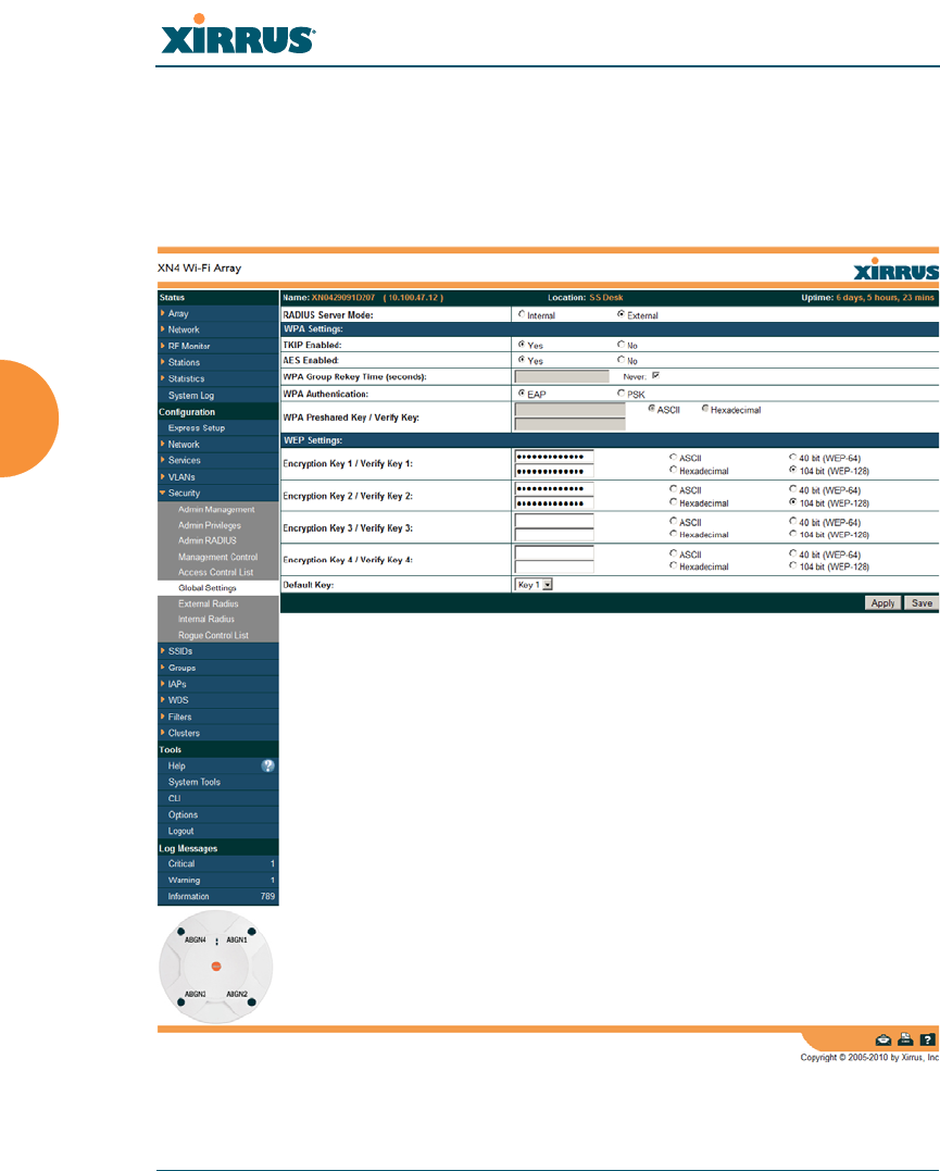
Wi-Fi Array
114 The Web Management Interface
An Overview
The WMI is an easy-to-use graphical interface to your Wi-Fi Array. It allows you
to configure the product to suit your individual requirements and ensure that the
unit functions efficiently and effectively.
Figure 41. Web Management Interface

Wi-Fi Array
The Web Management Interface 115
Structure of the WMI
The content of the WMI is organized by function and hierarchy, shown in the
following table. Click on any item below to jump to the referenced destination.
Status Windows
Array Status Windows
Array Summary
Array Information
Array Configuration
Admin History
Network Status Windows
Network Map
Spanning Tree Status
Routing Table
ARP Table
DHCP Leases
Connection Tracking/NAT
CDP Neighbors
Network Assurance
RF Monitor Windows
IAPs
Spectrum Analyzer
Intrusion Detection
Station Status Windows
Stations
Location Map
RSSI
Signal-to-Noise Ratio (SNR)
Noise Floor
Max by IAP
Statistics Windows
IAP Statistics Summary
Per-IAP Statistics
Network Statistics
VLAN Statistics
WDS Statistics
Filter Statistics
Station Statistics
Per-Station Statistics
System Log Window

Wi-Fi Array
116 The Web Management Interface
Configuration Windows
Express Setup
Network
Network Interfaces
DNS Settings
CDP Settings
Services
Time Settings (NTP)
NetFlow
Wi-Fi Tag
System Log
SNMP
DHCP Server
VLANs
VLAN Management
Security
Admin Management
Admin Privileges
Admin RADIUS
Management Control
Access Control List
Global Settings
External Radius
Internal Radius
Rogue Control List
SSIDs
SSID Management
Active IAPs
Groups
Group Management
Configuration Windows (cont’d)
IAPs
IAP Settings
Global Settings (IAP)
Global Settings .11a
Global Settings .11bg
Global Settings .11n
Advanced RF Settings
LED Settings
WDS
WDS Client Links
Filters
Filter Lists
Filter Management
Clusters
Cluster Definition
Cluster Management
Cluster Operation
Tool Windows
System Tools
CLI
Options
Logout
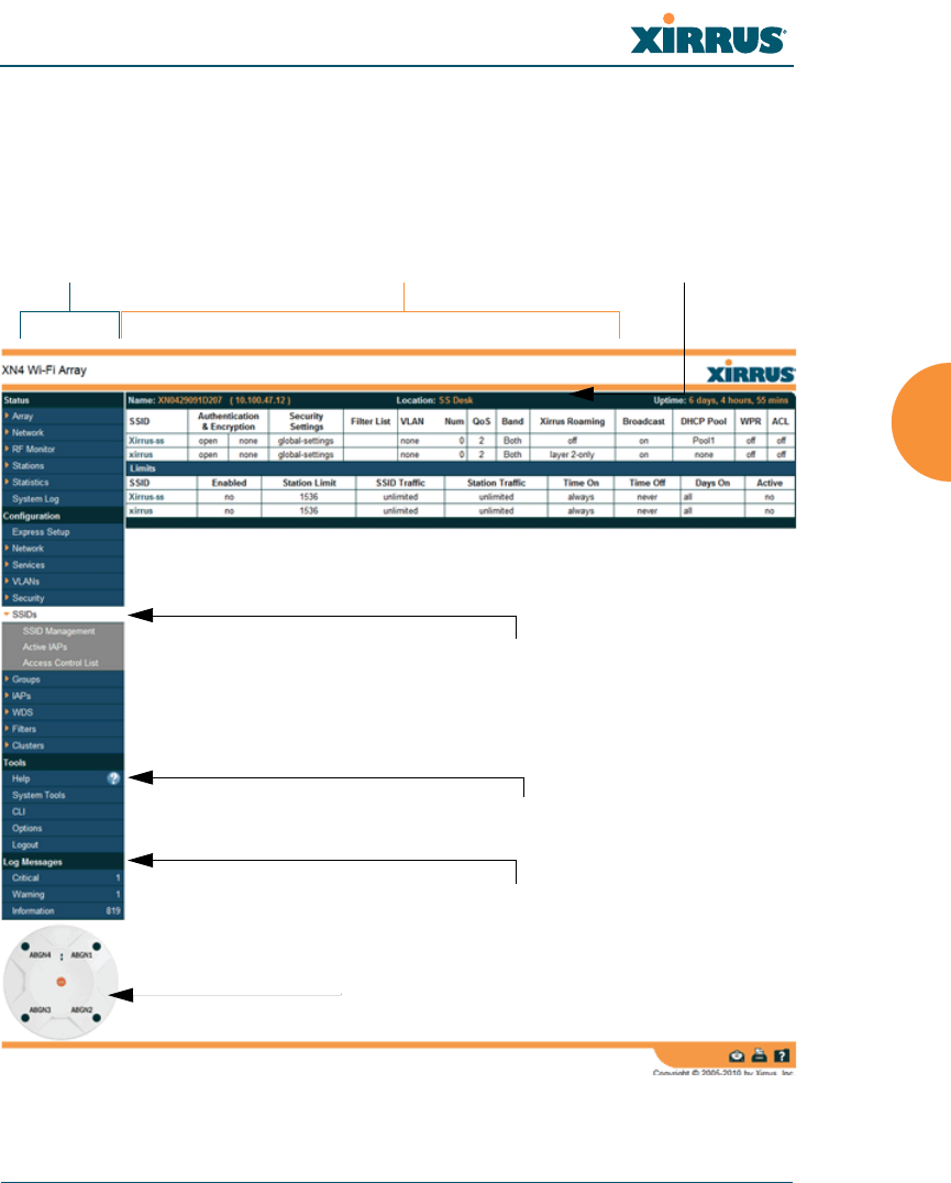
Wi-Fi Array
The Web Management Interface 117
User Interface
The WMI has been designed with simplicity in mind, making navigation quick
and easy. In the following example, you’ll see that windows are divided into left
and right frames.
Figure 42. WMI: Frames
Left frame Right frame Array info
Click to configure/view statistics
Log Message counters
Pull-down menu
Help

Wi-Fi Array
118 The Web Management Interface
The left frame contains three main elements:
Configuration menu organized by function (for example, radio interfaces,
security, etc.). Click the heading to display a summary of its current
configuration, as well as an associated pull-down menu.
Three Log Messages counters are located at the bottom of the menu. They
provide a running total of messages generated by the ArrayOS Syslog
subsystem during your session — organized into Critical, Warning, and
General messages. Click on a counter to display the associated Syslog
messages. Messages at the selected level or higher will be shown. For
more information, please see “System Log Window” on page 168.
The Array representation contains shortcut links. Click a radio to view
statistics for it. Click the center of the Array to display the IAP Settings
window, which allows you to configure the Array’s radios.
The right frame displays the status information or configuration parameters for
the Wi-Fi Array. This is where you review the Array’s current status and activity
or input data (if you want to make changes). The green Array information bar at
the top of the frame describes the Array — the Name and IP address allow you to
quickly confirm that WMI is connected to the correct Array. The current Uptime
since the last reboot is also shown.
Note that WMI provides options which allow you to change its appearance and
behavior. You may change:
Style — changes the colors and appearance of WMI (i.e., its “skin”).
Refresh Interval — the refresh time when automatic refresh is selected.
Close menu section when deselected — changes the behavior of the
menu in the left frame.
Clear screen when loading new page.
See “Options” on page 337 for more information.
Some settings are only available if the Array’s license includes appropriate
Xirrus Advanced Feature Sets. If a setting is unavailable (grayed out),
then your license does not support the feature. See “About Licensing and
Upgrades” on page 325.
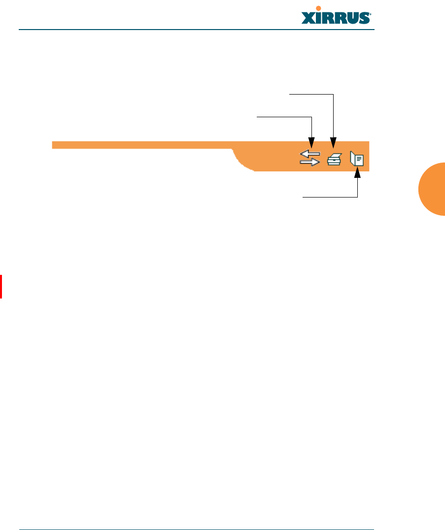
Wi-Fi Array
The Web Management Interface 119
Utility Buttons
At the bottom of each window you will find a set of useful buttons — a Feedback
button, a Print button and a Help button.
Figure 43. WMI: Utility Buttons
Click on the Feedback button to generate a Web page that allows you to
submit your comments to Xirrus, Inc. You can also access the feedback
page at http://www.xirrus.com/public/feedback/. Refer to Figure 44 on
page 120 to see a sample of the feedback form.
Click on the Print button to send a print file of the active window to your
local printer.
Click on the Help button to access the Array’s online help system.
Submitting Your Comments
When submitting comments via the Feedback button (Figure 44 , ensure that you
provide as much detail as possible, including your contact information, the
product model number that the comment relates to, and the ArrayOS software
version (if known). When finished, click on the Submit button to submit your
comment.
Print button
Help button
Feedback button
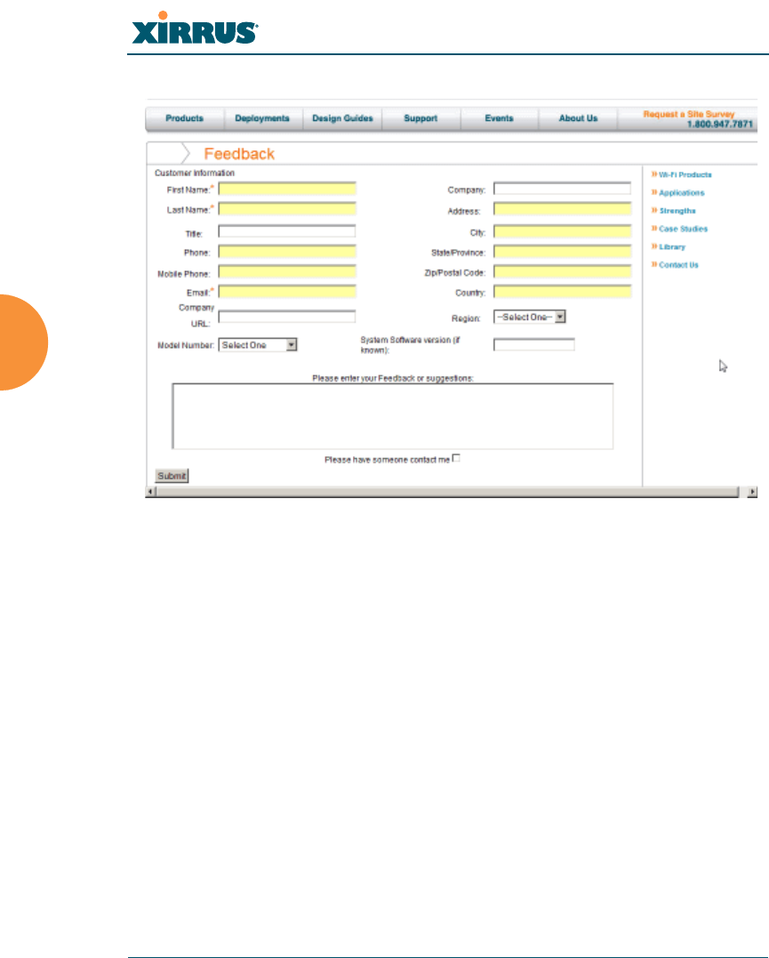
Wi-Fi Array
120 The Web Management Interface
Figure 44. Feedback Form
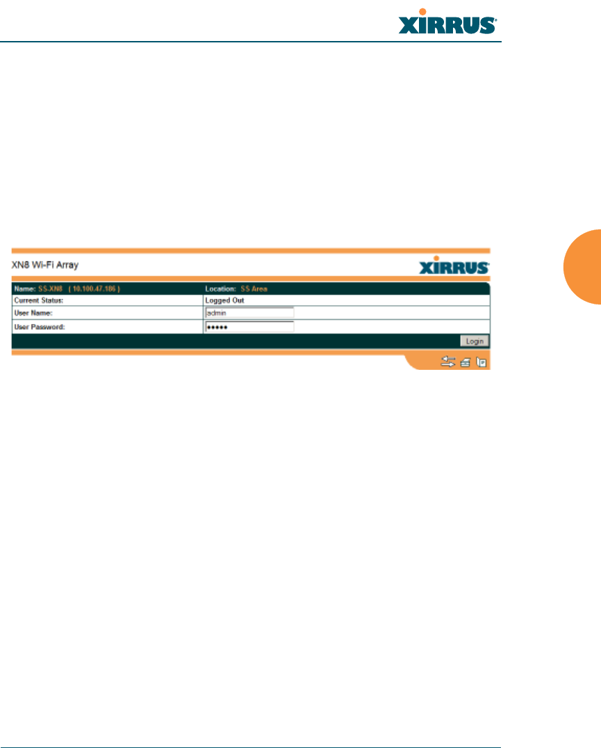
Wi-Fi Array
The Web Management Interface 121
Logging In
Use this procedure to log in to the WMI via your Web browser.
1. Establish a network connection and open your Web browser.
2. Connect to the Wi-Fi Array via its default IP address (10.0.2.1 for both
Gigabit 1 and Gigabit 2 Ethernet ports) or via a DHCP assigned IP
address.
3. To log in to the Array’s Web Management Interface, enter admin when
prompted for a user name and password.
Figure 45. Logging In to the Wi-Fi Array
Applying Configuration Changes
When you have defined all your settings in any WMI configuration window, you
must click on the Apply button for the changes to take effect in the current
session, or click on the Save button to apply changes to this session and write
your changes, so they will be preserved after a reboot.
Character Restrictions
When inputting strings in the WMI (for example, assigning SSIDs, host name,
password, etc.), use common alphanumeric characters. Some of the fields in the
WMI will not accept special characters, so use of the following characters should
typically be avoided:
&<>' “/ \

Wi-Fi Array
122 The Web Management Interface

Wi-Fi Array
Viewing Status on the Wi-Fi Array 123
Viewing Status on the Wi-Fi
Array
These windows provide status information and statistics for your Array using the
product’s embedded Web Management Interface (WMI). You cannot make
configuration changes to your Array from these windows. The following topics
have been organized into functional areas that reflect the flow and content of the
Status section of the navigation tree in the left frame of the WMI.
“Array Status Windows” on page 123
“Network Status Windows” on page 129
“RF Monitor Windows” on page 139
“Station Status Windows” on page 147
“Statistics Windows” on page 160
“System Log Window” on page 168
Configuration and Tools windows are not discussed here. For information on
these windows, please see:
“Configuring the Wi-Fi Array” on page 171
“Using Tools on the Wi-Fi Array” on page 323
Array Status Windows
The following Array Status windows are available:
Array Summary — displays information on the configuration of all Array
interfaces, including IAPs.
Array Information — provides version/serial number information for all
Array components.
Array Configuration — shows all configuration information for the Array
in text format.
Admin History — shows all current and past logins since the last reboot.
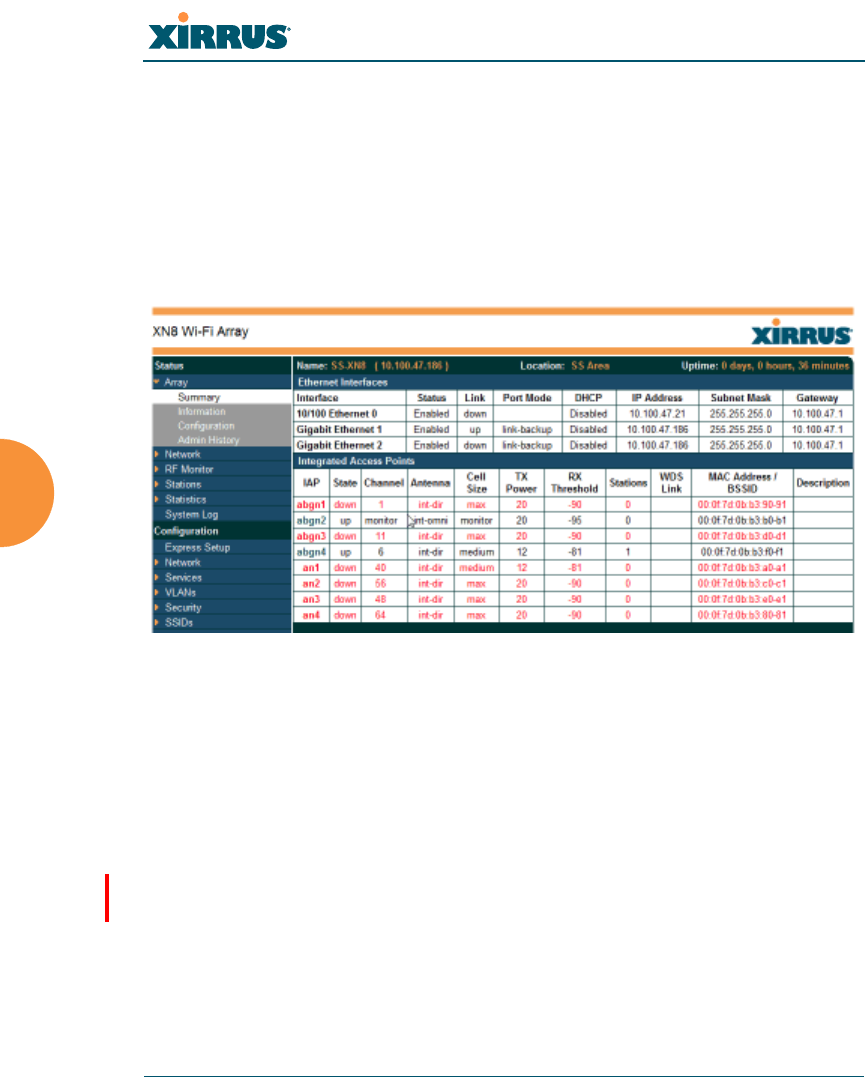
Wi-Fi Array
124 Viewing Status on the Wi-Fi Array
Array Summary
This is a status only window that provides a snapshot of the global configuration
settings for all Wi-Fi Array network interfaces and IAPs. You must go to the
appropriate configuration window to make changes to any of the settings
displayed here — configuration changes cannot be made from this window.
Clicking on an interface or IAP will take you to the proper window for making
configuration changes.
Figure 46. Array Summary
Content of the Array Summary Window
The Array Summary window is sub-divided into the Ethernet Interfaces section
and the Integrated Access Points (radio) section, providing you with the
following information:
Ethernet Interfaces Section
This section provides information about network interface devices. To
make configuration changes to these devices, go to “Network Interfaces”
on page 180.
•Interface: Lists the network interfaces that are available on the Array
(10/100 Ethernet 0, Gigabit Ethernet 1 and Gigabit Ethernet 2).
•Status: Shows the current state of each interface, either enabled or
disabled.
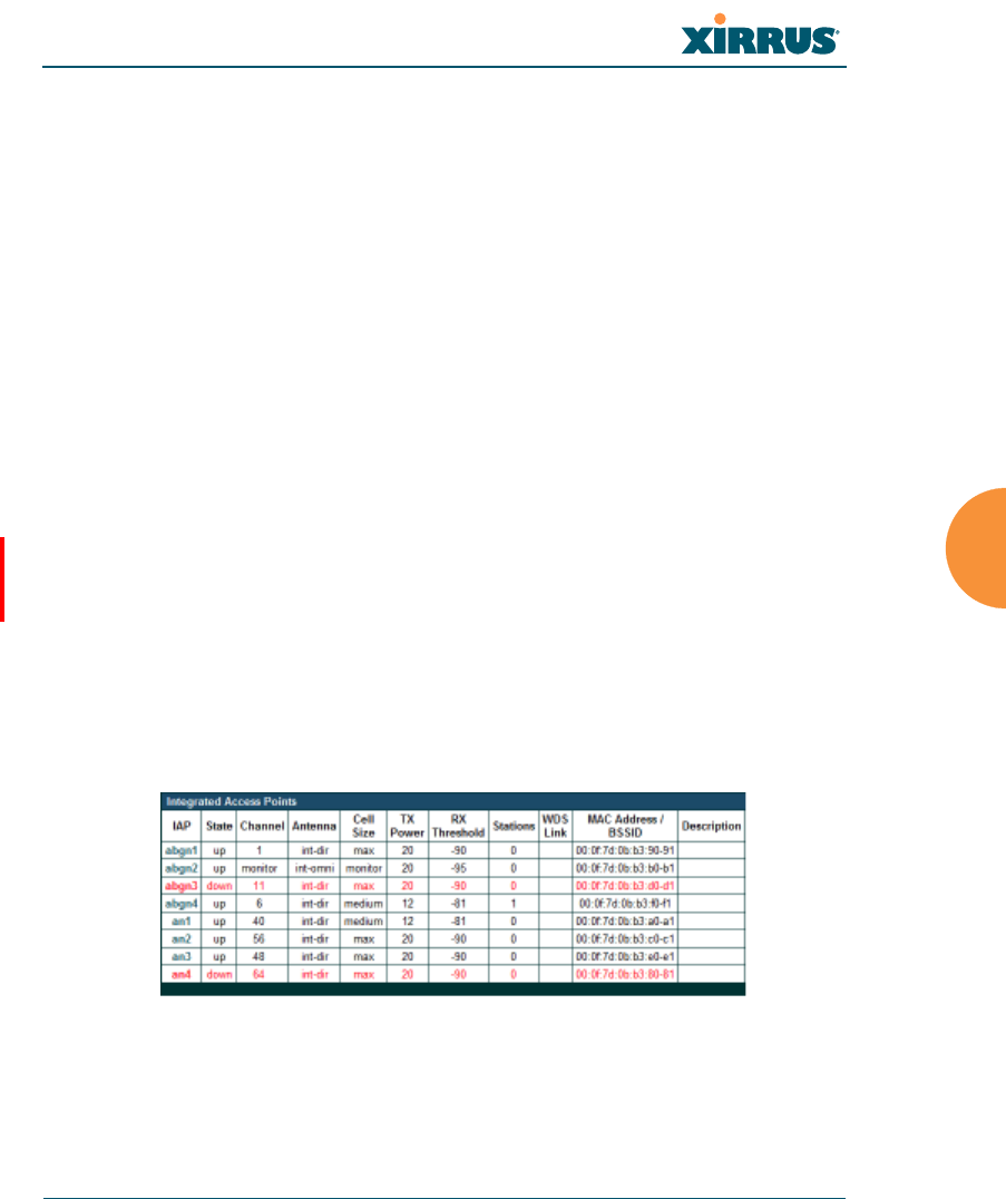
Wi-Fi Array
Viewing Status on the Wi-Fi Array 125
•Link: Shows whether the link on this interface is up or down.
•DHCP: Shows whether DHCP on this port is enabled or disabled.
•IP Address: Shows the current IP address assigned to each network
interface device.
•Subnet Mask: Shows the subnet mask, which defines the number of
IP addresses that are available on the routed subnet where the Array
is located.
•Gateway: Shows the IP address of the router that the Array uses to
transmit data to other networks.
Integrated Access Points Section
This section provides information about the Integrated Access Points
(IAPs) that are contained within the Array. How many IAPs are listed
depends on which product model you are using (16 IAPs for the XN16 or
XS16; 12 IAPs for the XN12; 8 IAPs for the XR 48xx or XN8 or XS8; and 4
IAPs for the XR 44xx or XN4 or XS4). To make configuration changes to
these IAPs, go to “IAP Settings” on page 271.
•IAP: Lists the IAPs that are available on the Array.
•State: Shows the current state of each IAP, either up or down. IAPs
that are down are shown in RED. Figure 47 shows an example where
IAP a3 is down.
Figure 47. Disabled IAP (Partial View)
•Channel: Shows which channel each IAP is using, and the channel
setting. To avoid co-channel interference, adjacent radios should not

Wi-Fi Array
126 Viewing Status on the Wi-Fi Array
be using adjacent channels. To make channel selections for a specific
IAP, go to “IAP Settings” on page 271.
•Antenna: Shows which antenna is being used by each IAP.
•Cell Size: Indicates which cell size setting is currently active for each
IAP — small, medium, large, max, automatic, or manually defined by
you. The cell size of an IAP is a function of its transmit power and
determines the IAP’s overall coverage. To define cell sizes, go to “IAP
Settings” on page 271. For additional information about cell sizes and
the importance of planning for and defining the optimum cell sizes
for your Array, go to “Coverage and Capacity Planning” on page 62.
Figure 48. IAP Cells
•Tx Power: Shows the transmit power for each IAP.
•Rx Threshold: Shows the receive threshold for each IAP.
•Stations: Informs you how many client stations are currently
associated with each IAP. XR and XN Arrays can handle up to 96
concurrent users per individual IAP, thus 16-port XN models can
handle 1536 users per Array.
•WDS Link: The WDS Link on this radio (if any). See “WDS” on
page 305.
•MAC Address/BSSID: Shows the MAC address for each IAP.
•Description: The description (if any) that you set for this IAP.
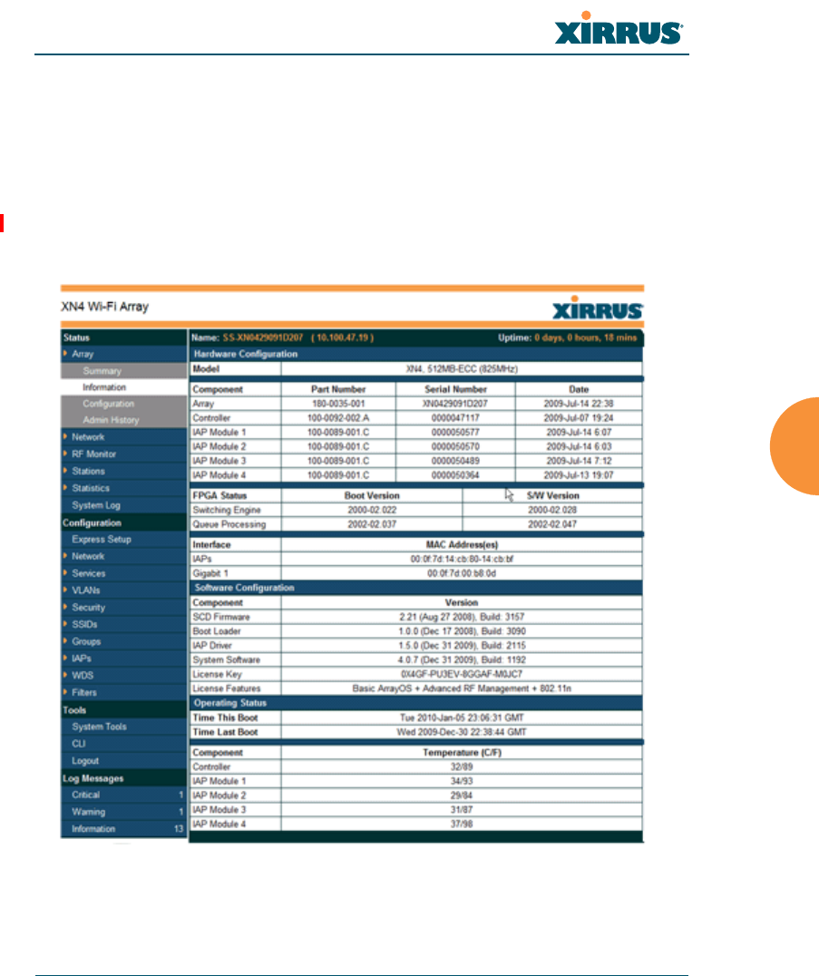
Wi-Fi Array
Viewing Status on the Wi-Fi Array 127
Array Information
This is a status only window that shows you the current firmware versions
utilized by the Array, serial numbers assigned to each module, MAC addresses,
licensing information, recent boot timestamps, and current internal temperatures.
Note that the License Features row lists the features that are supported by your
Array’s license. See “About Licensing and Upgrades” on page 325 and
“Advanced Feature Sets” on page 20 for more information.
Figure 49. Array Information
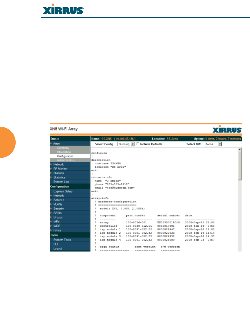
Wi-Fi Array
128 Viewing Status on the Wi-Fi Array
You cannot make configuration changes in this window, but if you are
experiencing issues with network services, you may want to print the content of
this window for your records.
Array Configuration
This is a status only window that allows you to display the configuration settings
assigned to the Array, based on the following filter options:
Running — displays the current configuration (the one running now).
Saved — displays the saved configuration from this session.
Lastboot — displays the configuration as it was after the last reboot.
Factory — displays the configuration established at the factory.
Figure 50. Show Configuration
If you want to see just the differences between the Running, Saved, Lastboot, and
Factory configurations, you can do this by choosing a configuration option from
the Select Config pull-down menu then selecting an alternative configuration
option from the Select Diff pull-down menu.
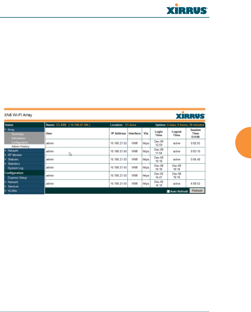
Wi-Fi Array
Viewing Status on the Wi-Fi Array 129
To also include the default configuration settings in the output, choose your
configuration then click in the Include Defaults check box. If Include Defaults is
disabled, then only the changes from the default configuration are shown.
Admin History
It is useful to know who else is currently logged in to an array while you're
configuring it. It's also nice to see who has logged in since the array booted. This
status-only window shows you all administrator logins to the Array that have
occurred since the last reboot. To determine who is currently logged in, check
which entries say active in the Logout Time column.
Figure 51. Admin Login History
Network Status Windows
The following Network Status windows are available:
Network — displays a summary of network interface settings.
Network Map — displays information about this Array and neighboring
Arrays that have been detected.
Spanning Tree Status — displays the spanning tree status of network
links on this Array.
Routing Table — displays information about routing on this Array.
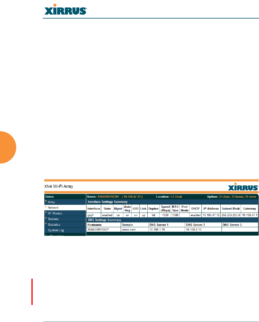
Wi-Fi Array
130 Viewing Status on the Wi-Fi Array
ARP Table — displays information about Address Resolution Protocol on
this Array.
DHCP Leases — displays information about IP addresses (leases) that the
Array has allocated to client stations.
Connection Tracking/NAT — lists connections that have been established
for client stations.
CDP Neighbors — lists neighboring network devices using Cisco
Discovery Protocol.
Network Assurance — shows results of connectivity tests for network
servers.
Network
This window provides a snapshot of the configuration settings currently
established for Array’s wired interfaces. Depending on the model, this may
include the 10/100 Ethernet 0 interface and the Gigabit 1 and Gigabit 2 interfaces.
DNS Settings are summarized as well. You can click on any item in the Interface
column to go to the associated configuration window.
Figure 52. Network Settings
WMI windows that allow you to change or view configuration settings associated
with the network interfaces include:
“Network Interfaces” on page 180
“DNS Settings” on page 187
“CDP Settings” on page 189
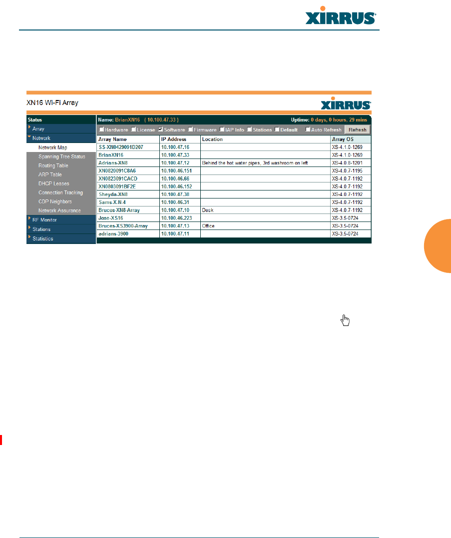
Wi-Fi Array
Viewing Status on the Wi-Fi Array 131
Network Map
This window offers detailed information about this Array and all neighboring
Arrays, including how the Arrays have been set up within your network.
Figure 53. Network Map
The Network Map has a number of options at the top of the page that allow you
to customize your output by selecting from a variety of information that may be
displayed. You may sort the rows based on any column that has an active column
header, indicated when the mouse pointer changes to the hand icon . Click
Refresh to update the information at any time. Click Auto Refresh to instruct the
Array to refresh this window automatically.
Content of the Network Map Window
By default, the network map shows the following status information for each
Array:
Array Name: The host name assigned to the Array. To establish the host
name, go to “Express Setup” on page 173. You may click the host name to
access WMI for this Array.
IP Address: The Array’s IP address. You may click the address to access
WMI for this Array. If DHCP is enabled, the Array’s IP address is
assigned by the DHCP server. If DHCP is disabled, you must assign a

Wi-Fi Array
132 Viewing Status on the Wi-Fi Array
static IP address. To enable DHCP or to assign a static IP address for the
Array, go to “Express Setup” on page 173.
Location: The location assigned to the Array. To establish the location
information, go to “Express Setup” on page 173.
Array OS: The software version running on the Array.
IAP: The number of IAPs on the Array.
(IAP) Up: Informs you how many IAPs are currently up and running. To
enable or disable all IAPs, go to “Express Setup” on page 173. To enable
or disable individual IAPs, go to “IAP Settings” on page 271.
SSID: Informs you how many SSIDs have been assigned for the Array. To
assign an SSID, go to “SSID Management” on page 248.
(SSID) On: Informs you how many SSIDs are enabled. To enable or
disable SSIDs, go to “SSID Management” on page 248.
In Range: Informs you whether the Array is within wireless range of
another Wi-Fi Array.
Fast Roam: Informs you whether or not the Xirrus fast roaming feature is
enabled. This feature utilizes the Xirrus Roaming Protocol (XRP) ensuring
fast and seamless roaming capabilities between IAPs or Arrays at both
Layer 2 and Layer 3. To enable or disable fast roaming, go to “Global
Settings (IAP)” on page 277.
Uptime (D:H:M): Informs you how long the Array has been up and
running (in Days, Hours and Minutes).
To see additional information, select from the following checkboxes at the bottom
of the page. This will show the columns described below.
Hardware
Model: The model number of each Array (XN16, XS4, etc.), plus the
amount of RAM memory and the speed of the processor.
Serial: Displays the serial number of each Array.
License
License Key: The license key of each Array.

Wi-Fi Array
Viewing Status on the Wi-Fi Array 133
Licensed Features: Lists the optional features enabled by the key, if any.
Software (enabled by default)
Enable/disable display of the Array OS column.
Firmware
Boot Loader: The software version number of the boot loader on each
Array.
SCD Firmware: The software version number of the SCD firmware on
each Array.
IAP Info (enabled by default)
Enable/disable display of the IAP/Up columns.
Stations
Stations: Tells you how many stations are currently associated to each
Array. To deauthenticate a station, go to “Stations” on page 148.
The columns to the right (H, D, W, and M) show the highest number of
stations that have been associated over various periods of time: the
previous hour, day, week, and month.
Default
Sets the columns displayed to the default settings. By default, only
Software and IAP Info are selected.
Spanning Tree Status
Multiple active paths between stations can cause loops in the network. If a loop
exists in the network topology, the potential exists for the duplication of
messages. The spanning tree protocol is a link management protocol that
provides path redundancy while preventing undesirable loops. For a wireless
network to function properly, only one active path can exist between two stations.
To facilitate path redundancy, the spanning tree protocol defines a tree that spans
all stations in the network and forces certain redundant data paths into a standby
(blocked) state. If one segment in the spanning tree becomes unreachable, the
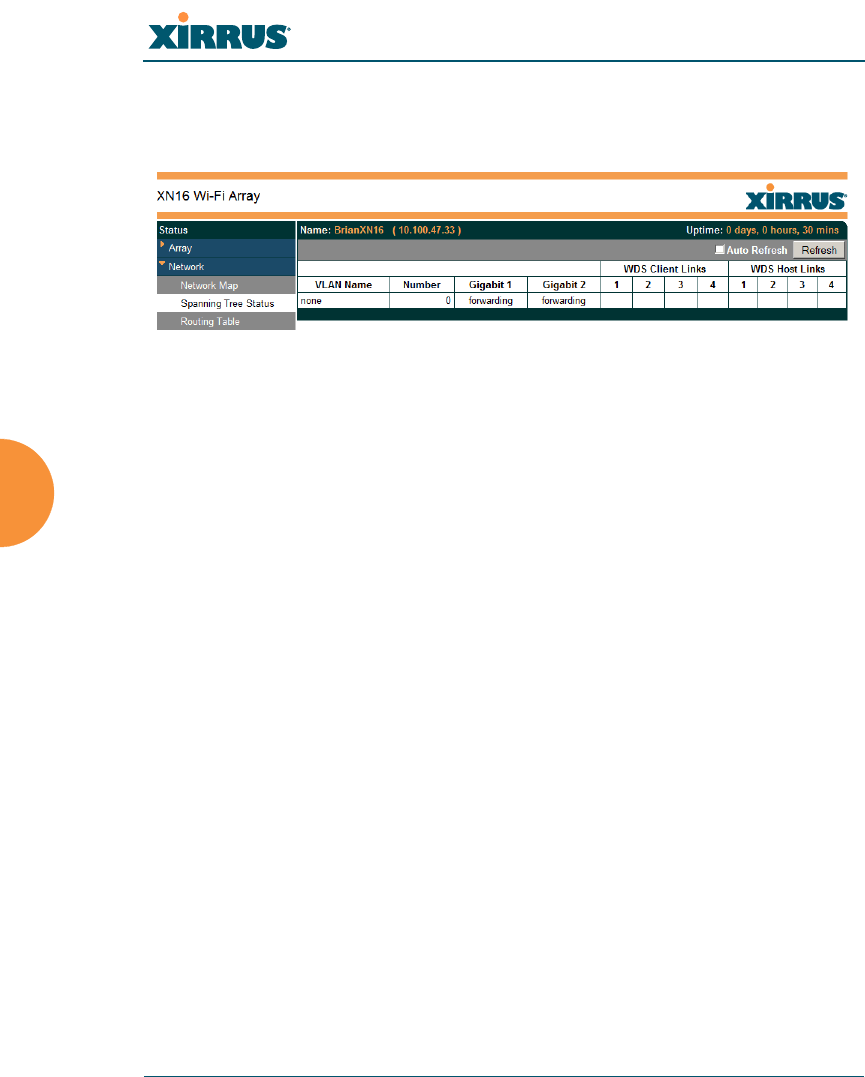
Wi-Fi Array
134 Viewing Status on the Wi-Fi Array
spanning tree algorithm reconfigures the network topology and reestablishes the
link by activating the standby path. The spanning tree function is transparent to
client stations.
Figure 54. Spanning Tree Status
This window shows the spanning tree status (forwarding or blocked) for path
segments that terminate on the gigabit ports and WDS links of this Array. You
may sort the rows based on the VLAN Name or Number columns by clicking the
column header. Click Refresh to update the information at any time. Click Auto
Refresh to instruct the Array to refresh this window automatically.
See Also
Network
Network Interfaces
Network Status Windows
VLANs
WDS
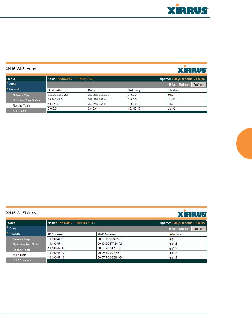
Wi-Fi Array
Viewing Status on the Wi-Fi Array 135
Routing Table
This status-only window lists the entries in the Array’s routing table. The table
provides the Array with instructions for sending each packet to its next hop on its
route across the network.
Figure 55. Routing Table
See Also
VLANs
Configuring VLANs on an Open SSID
ARP Table
This status-only window lists the entries in the Array’s ARP table. For a device
with a given IP address, this table lists the device’s MAC address. It also shows
the Array interface through which this device may be reached. The table typically
includes devices that are on the same local area network segment as the Array.
Figure 56. ARP Table
See Also
Routing Table
ARP Filtering
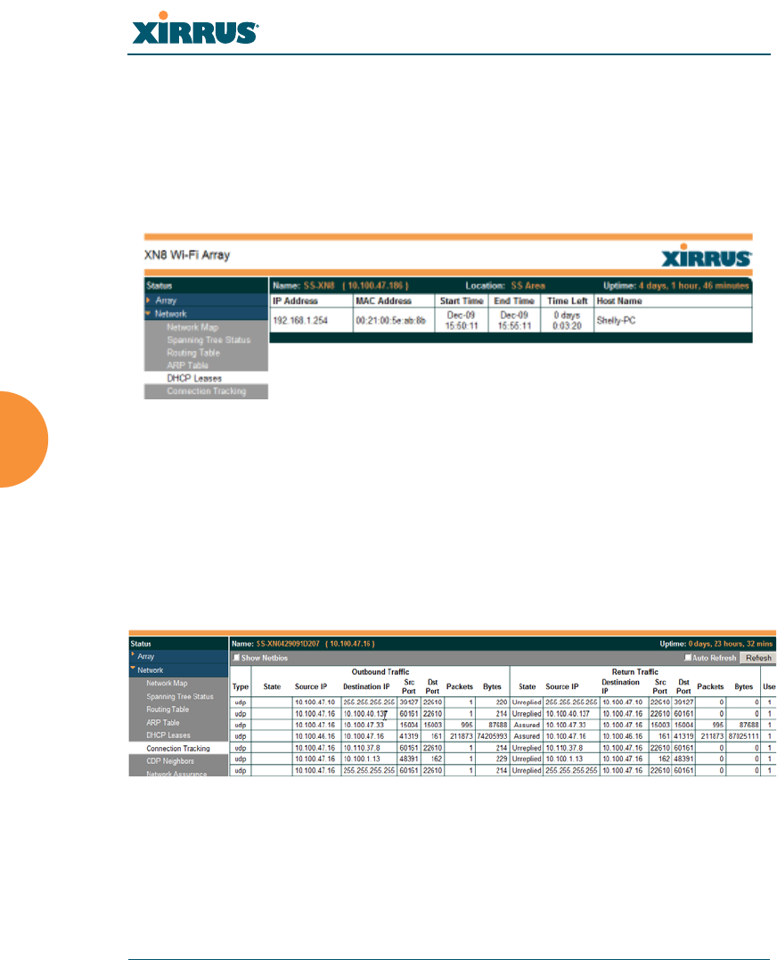
Wi-Fi Array
136 Viewing Status on the Wi-Fi Array
DHCP Leases
This status-only window lists the IP addresses (leases) that the Array has
allocated to client stations. For each, it shows the IP address assigned from one of
the defined DHCP pools, and the MAC address and host name of the client
station. The start and end time of the lease show how long the allocation is valid.
The same IP address is normally renewed at the expiration of the current lease.
Figure 57. DHCP Leases
See Also
DHCP Server
Connection Tracking/NAT
This status-only window lists the session connections that have been created on
behalf of clients. This table may also be used to view information about current
NAT sessions.
Figure 58. Connection Tracking
Click the Show Netbios checkbox at the bottom of the page to display NetBIOS
name information for the source and destination location of the connection. The
Netbios columns will replace traffic statistics columns.
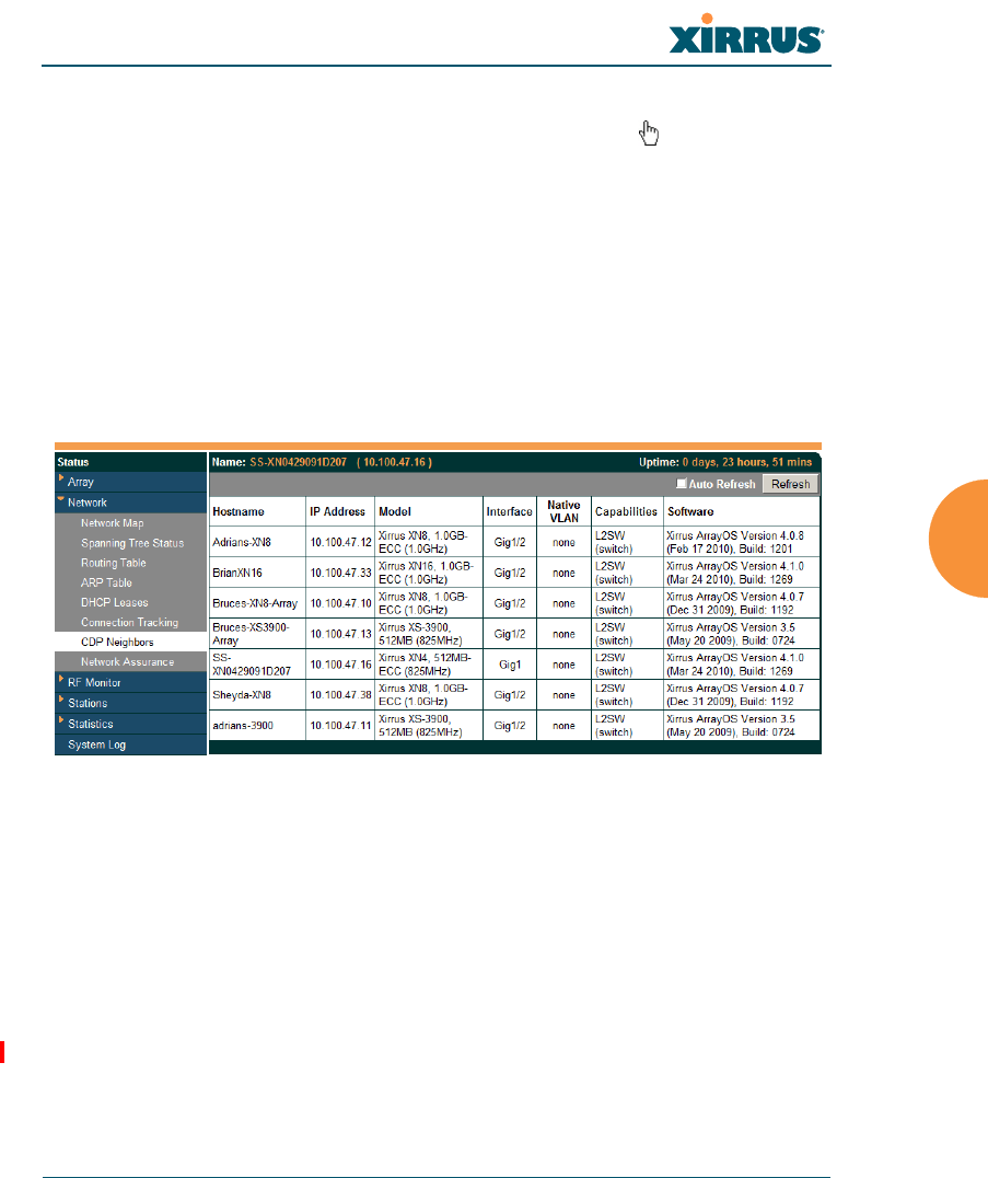
Wi-Fi Array
Viewing Status on the Wi-Fi Array 137
You may sort the rows based on any column that has an active column header,
indicated when the mouse pointer changes to the hand icon . Click Refresh to
update the information at any time. Click Auto Refresh to instruct the Array to
refresh this window automatically.
See Also
Filters
CDP Neighbors
This status-only window lists devices on the Array’s network that support the
Cisco Discovery Protocol (CDP).
Figure 59. CDP Neighbors
The Array performs discovery on the network on an ongoing basis. This list
shows the devices that have been discovered — Cisco devices and other devices
on the network that have CDP running. For each, it shows the device’s host name,
IP address, manufacturer and model name, the device interface that is connected
to the network (i.e., the port that was discovered), and the network capabilities of
the device (switch, router, supported protocols, etc.).
CDP must be enabled on the Array in order to gather and display this
information. See “CDP Settings” on page 189.
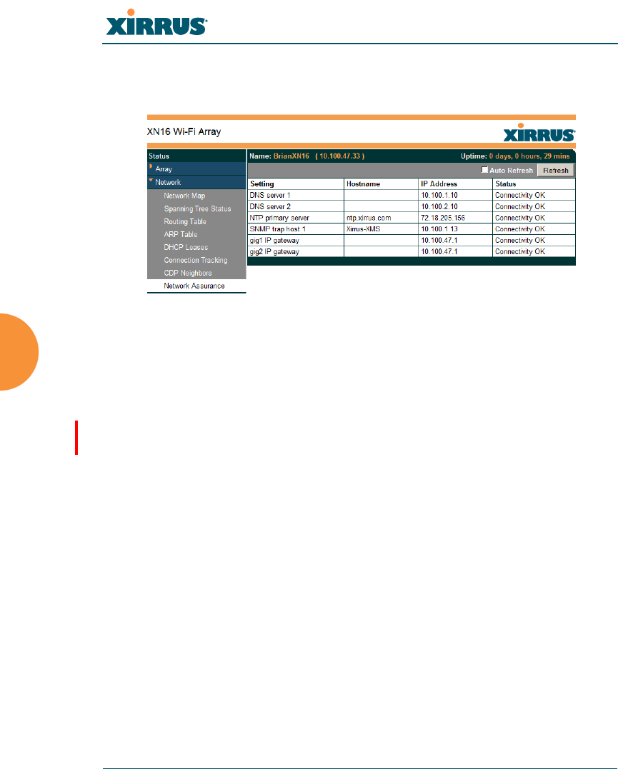
Wi-Fi Array
138 Viewing Status on the Wi-Fi Array
Network Assurance
This status-only window shows the results of ongoing network assurance testing.
Figure 60. Network Assurance
The Array checks connectivity to network servers that you have configured (for
example, DNS and NTP servers) on an ongoing basis. For each server, this list
shows the server’s host name (if any), IP address, and status.
Network assurance must be enabled on the Array in order to perform these
connectivity tests and display this information. See “Management Control” on
page 222.
See Also
Management Control

Wi-Fi Array
Viewing Status on the Wi-Fi Array 139
RF Monitor Windows
Every Wi-Fi Array includes an integrated RF spectrum analyzer as a standard
feature. The spectrum analyzer allows you to characterize the RF environment by
monitoring throughput, signal, noise, errors, and interference levels continually
per channel. This capability uses the built-in threat-sensor radio abg(n)2. The
associated software is part of the ArrayOS.
The following RF Status windows are available:
IAPs — displays current statistics and RF measurements for each of the
Array’s IAPs.
Spectrum Analyzer — displays current statistics and RF measurements
for each of the Array’s channels.
Intrusion Detection — displays rogue APs that have been detected by the
Array.
Some status information is only available if the Array’s license includes
Advanced Feature Sets. For example, the Spectrum Analyzer requires the
Xirrus Advanced RF Analysis Manager (RAM). If a feature is
unavailable, then your license does not support the feature and you will get
an error message if you try to set the feature. See “About Licensing and
Upgrades” on page 325.
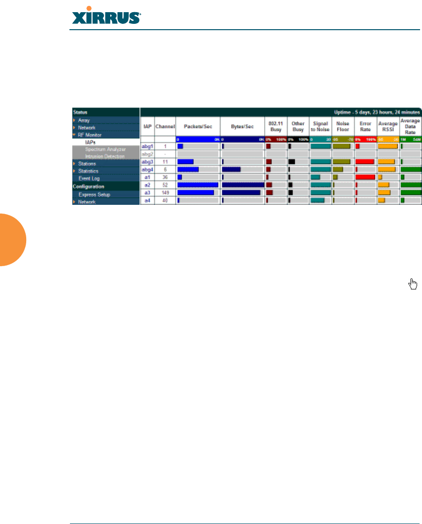
Wi-Fi Array
140 Viewing Status on the Wi-Fi Array
IAPs
The RF Monitor — IAPs window displays traffic statistics and RF readings
observed by each Array IAP (radio). Note that the data is an instantaneous
snapshot for the IAP — it is not an average or a cumulative total.
Figure 61. RF Monitor — IAPs
Figure 61 presents the data as a graphical display, enabled by selecting the Graph
checkbox on the lower left. If this option is not selected, data is presented as a
numerical table. You may sort the rows based on any column that has an active
column header, indicated when the mouse pointer changes to the hand icon .
Click Refresh to update the information at any time. Click Auto Refresh to
instruct the Array to refresh this window automatically.

Wi-Fi Array
Viewing Status on the Wi-Fi Array 141
Spectrum Analyzer
Spectrum analysis on Wi-Fi Arrays is a distributed capability that automatically
covers the entire Wi-Fi network, since a sensor is present in every unit. Arrays
monitor the network 24/7 and analyze interference anywhere in the network
from your desk. There’s no need to walk around with a device as with traditional
spectrum analyzers, thus you don’t have to be in the right place to find outside
sources that may cause network problems or pose a security threat. The Array
monitors all 802.11 radio bands (a/b/g/n), not just those currently used for data
transmission.
The RF Spectrum Analyzer window displays instantaneous traffic statistics and
RF readings for all channels, as measured by the Array’s abg(n)2 radio. This
differs from the RF Monitor-IAPs window, which displays values measured by
each IAP radio for its current assigned channel. For the spectrum analyzer, the
abg(n)2 radio is in a listen-only mode, scanning across all Wi-Fi channels. Each
channel is scanned in sequence, for a 250 millisecond interval per channel. The
spectrum analyzer window presents the data as a graphical display of vertical bar
graphs for each statistic as shown in Figure 62 (the default presentation), or
horizontally as bar graphs or numerical RF measurements. The measurements
displayed are explained in “Spectrum Analyzer Measurements” on page 143.
As an aid to viewing data for a particular channel, click the channel number. The
channel will be highlighted down the page (or across the page for a rotated view,
in both text and graph modes). Click additional channels to highlight them for
easy comparison. To remove the highlighting from a channel, click the channel
number again. Click Refresh to update the information at any time. Click Auto
Refresh to instruct the Array to refresh this window automatically.
The RF measurements for this feature are obtained by IAP abg(n)2, which
must be set to monitor mode for any data to be available. See “IAP
Settings” on page 271.
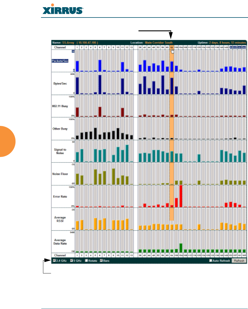
Wi-Fi Array
142 Viewing Status on the Wi-Fi Array
Figure 62. RF Spectrum Analyzer
The Spectrum Analyzer offers several display options:
Click Channel number to highlight
Select Display Options

Wi-Fi Array
Viewing Status on the Wi-Fi Array 143
To display horizontal bar graphs, click the Rotate checkbox at the bottom
of the data window.
In the rotated view, if you wish to view data as a numerical table, click the
Text checkbox. Click again to return to a graphical display. The text
option is only available in the rotated view.
When viewing a graphical display, click Bars to have the bar graphs
displayed against a gray background — you may find this easier on the
eyes. This operation is not available when Text is selected.
You may sort the rows based on any column that has an active column
header, indicated when the mouse pointer changes to the hand icon .
Sorting is only available in the rotated view.
At the bottom left of the frame, you may select whether to display only
2.4 GHz channels, 5 GHz channels, or both (the default is both). Note that
the data is an instantaneous snapshot — it is not an average or a
cumulative total.
Spectrum Analyzer Measurements
The spectrum analyzer displays the following information:
Packets/Sec: Total number of Wi-Fi packets per second on the channel,
both valid and errored packets.
Bytes/Sec: Total number of Wi-Fi bytes per second on the channel, valid
packets only.
802.11 Busy: Percentage of time that 802.11 activity is seen on the channel.
Other Busy: Percentage of time that the channel is unavailable due to
non-802.11 activity.
The total busy time (802.11 Busy plus Other Busy) will never total more
than 100%. The remaining time (100% minus total busy time) is quiet
time — the time that no activity was seen on the channel.
Signal to Noise: Average SNR (signal to noise ratio) seen on the channel,
calculated from the signal seen on valid 802.11 packets less the noise floor
level. A dash value “-“means no SNR data was available for the interval.

Wi-Fi Array
144 Viewing Status on the Wi-Fi Array
Noise Floor: Average noise floor reading seen on the channel (ambient
noise). A dash value “-“means no noise data was available for the
interval.
Error Rate: Percentage of the total number of Wi-Fi packets seen on the
channel that have CRC errors. The Error rate percentage may be high on
some channels since the monitor radio is set to receive at a very sensitive
level, enabling it to hear packets from devices at far distances.
Average RSSI: Average RSSI level seen on 802.11 packets received on the
channel. A dash value “-“means no RSSI data was available for the
interval.
Average Data Rate: Average data rate over time (per byte, not per packet)
seen on 802.11 packets received on the channel. A dash value “-“means
no data rate information was available for the interval. A higher date rate
(above 6 Mbps) typically indicates user data traffic on the channel.
Otherwise, the data rate reflects control packets at the lower basic rates.
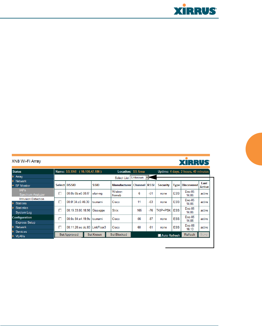
Wi-Fi Array
Viewing Status on the Wi-Fi Array 145
Intrusion Detection
This window displays all detected access points, according to the category you
select from the drop-down list at the top — either Unknown, Known or Approved.
This includes ad hoc access points (station-to-station connections). You can sort
the results based on the following parameters by clicking the desired column
header:
Figure 63. Intrusion Detection/Rogue AP List
The Intrusion Detection window provides the easiest method for designating
rogue APs as Known. Approved, or Unknown. Choose one or more APs using the
checkbox in the Select column, then set whether they are Approved, Known, or
Unknown using the buttons on the lower left.
SSID Security
BSSID Type
Manufacturer Discovered
Channel Last Active
RSSI
Select the type of AP to display

Wi-Fi Array
146 Viewing Status on the Wi-Fi Array
You can refresh the list at any time by clicking on the Refresh button, or click in
the Auto Refresh check box to instruct the Array to refresh the list automatically.
See Also
Network Map
Rogue Control List
SSIDs
SSID Management

Wi-Fi Array
Viewing Status on the Wi-Fi Array 147
Station Status Windows
The following Station Status windows are available:
Stations — this list describes all stations associated to the Array.
Location Map — displays a map showing the approximate locations of all
stations associated to the array.
RSSI — for each associated station, this displays the Received Signal
Strength Indicator at each of the Array’s IAPs.
Signal-to-Noise Ratio (SNR) — for each associated station, this displays
the SNR at each of the Array’s IAPs.
Noise Floor — for each associated station, this displays the ambient noise
(silence) value at each of the Array’s IAPs.
Max by IAP — for each IAP, this shows the historical maximum number
of stations that have been associated to it over various periods of time.
Some status information is only available if the Array’s license includes the
Xirrus Advanced RF Analysis Manager (RAM). If a feature is
unavailable, then your license does not support the feature and you will get
an error message if you try to set the feature. See “About Licensing and
Upgrades” on page 325.
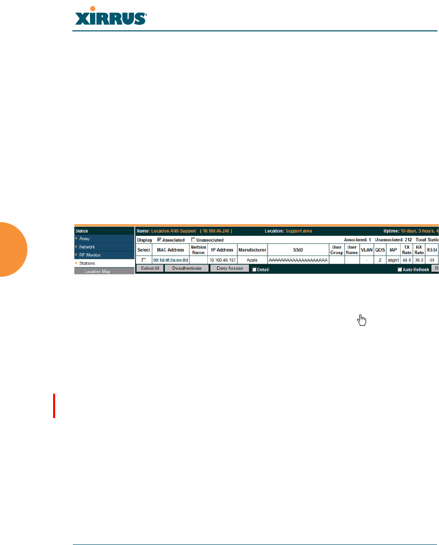
Wi-Fi Array
148 Viewing Status on the Wi-Fi Array
Stations
This status-only window shows client stations currently visible to the Array. You
may choose to view only stations that have associated to the Array, or only
stations that are not associated, or both, by selecting the appropriate checkboxes
above the list. The list shows the MAC address of each station, its NetBIOS name,
its IP address, its manufacturer, the SSID used for the association, the Group (if
any) that this station belongs to, the user name, its VLAN, its QoS, the IAP used
for the association, transmit and receive rates, the RSSI for each station, and how
long each association has been active (up time).
You may click the Detail checkbox at the bottom of the window to show a number
of additional columns, including security settings used by the connection, the
channel and band used, and additional RF measurements.
Figure 64. Stations
You may sort the rows based on any column that has an active column header,
indicated when the mouse pointer changes to the hand icon . Click again to
reverse the sort order. You may select a specific station and perform one of the
following actions by clicking the associated button:
Deny Access: Sends a de-authentication frame to the selected station and
explicitly denies it access by adding its MAC address to the Deny List in
the Access Control List window. To permit access again, go to “Access
Control List” on page 229 and delete the station from the Deny list.
Deauthenticate: Sends a de-authentication frame to the selected station.
The station may re-authenticate.
Click on the Refresh button to refresh the station list, or click in the Auto Refresh
check box to instruct the Array to refresh this window automatically.
See Also
Access Control List
Station Status Windows
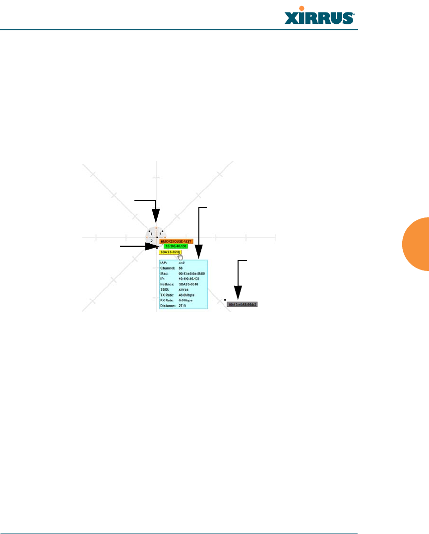
Wi-Fi Array
Viewing Status on the Wi-Fi Array 149
Location Map
The Location Map shows the approximate locations of stations relative to this
Array. The location of each station is computed based on the RSSI of its signal as
received by the Array. The distance is adjusted based on the environment setting
that you selected. You may display just the stations associated to this Array,
unassociated stations (shown in gray), or both. The station count is shown on the
right, above the map. You may also choose to display only 5 GHz stations (shown
in orange) or 2.4 GHz stations (shown in green), or both.
Figure 65. Location Map
The map and Array are shown as if you were looking down on the Array from
above, say from a skylight on the roof. Thus the positions of the radios abg(n)1 to
abg(n)4 are a mirror image of the way they are typically drawn when looking at
the face of the Array. Radios abg(n)1 to abg(n)4 are marked (1 to 4) on the map to
show the orientation of the Array.
A station is identified by the type of Preferred Label that you select: Netbios
Name, IP Address, MAC Address, or Manufacturer. If multiple stations are near
each other, they will be displayed slightly offset so that one station does not
completely obscure another. You may minimize a station that is not of interest by
clicking it. There is also a Minimize All button.
Associated Stations
orange - 5 GHz
green - 2.4GHz Unassociated Station
Hover mouse to
show details
Array
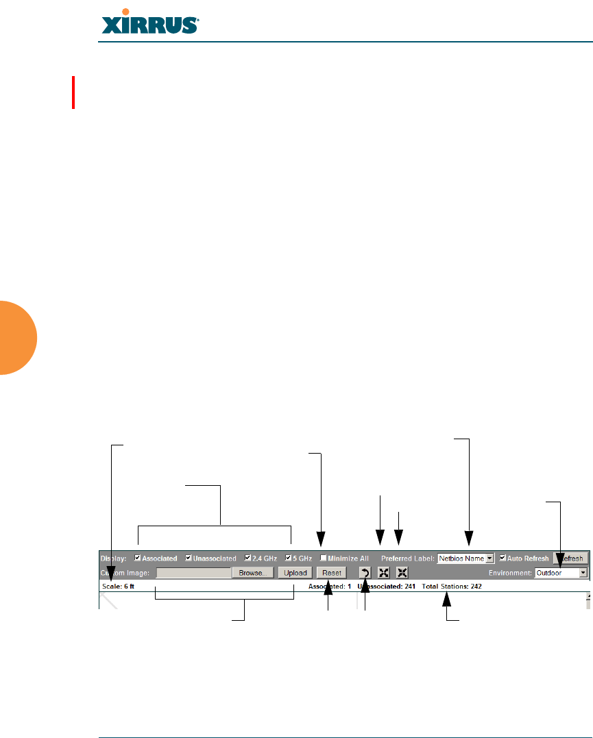
Wi-Fi Array
150 Viewing Status on the Wi-Fi Array
You may replace the range-finder background image above with your own
custom image of the floorplan of the area served by the Array — see “Working
with the Custom Image” on page 153
Hover the mouse over a station to show detailed information. (Figure 65) For a
station that is associated to this Array, the details include:
The IAP, Channel, and SSID to which the station is associated.
The MAC and IP address and Netbios name of the station.
The TX Rate and RX Rate of this connection.
The approximate Distance of this station from the Array. The distance is
estimated using the received signal strength and your environment
setting. The environment determines the typical signal attenuation due to
walls and other construction that affect signal reception.
Controls and items displayed on the Location Map window
Figure 66. Controls for Location Map
Display Associated/Unassociated: Select whether to display stations that
are associated to the Array, stations that are not associated, or both.
The Location Map has its own scroll bars in addition to the browser’s scroll
bars. If you narrow the browser window, the map’s scroll bar may be hidden.
Use the browser’s bottom scroll bar if you need to move it into view.
Stations
to display Environment
Setting
Replace background
Minimize stations
Reset display Rotate map
Zoom in
Zoom out
Scale Preferred
Label
Station counts
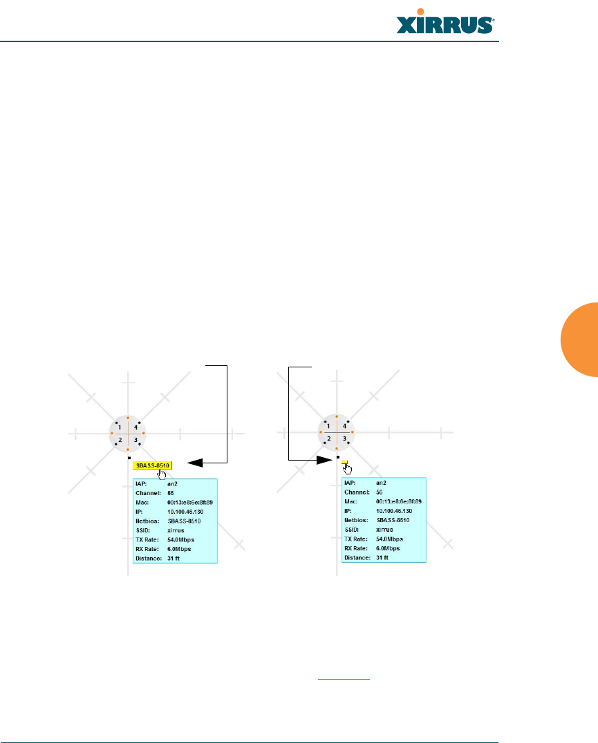
Wi-Fi Array
Viewing Status on the Wi-Fi Array 151
Display 2.4 GHz/5 GHz: Select whether to display 802.11bg(n) stations,
or 802.11a(n) stations, or both.
Minimize All: All stations are shown by default with their NetBIOS
name or IP or MAC address. If the map is too cluttered, you can reduce
the display for each station to a small rectangle. (Figure 67) You may still
display detailed information for the station by hovering over it. To
enlarge all rectangles, clear the Minimize All checkbox.
Preferred Label: This field is located on the top of the window towards
the right. It selects the type of label to be displayed for stations: Netbios
Name, IP Address, MAC Address, or Manufacturer. If you select
NetBIOS (this is the default), then that name, if known, will be used to
label each Array. Else, its IP or MAC address will be used, in that order.
Auto Refresh: Instructs the Array to refresh this window automatically.
Refresh: Updates the stations displayed.
Figure 67. Minimizing stations
Custom Image: Use this feature to replace the default background image
with your own image of the floor plan of your location. Click the Browse
button and browse to the desired file on your computer. This may be a
.gif, .jpg, .jpeg., .png, .htm, or .html file. ??OK?? The scale of the file
should be 100 feet per inch. Then click Upload (see below). For more
Normal station display Minimized station display
Wi-Fi Array
152 Viewing Status on the Wi-Fi Array
information on using the custom, image, see “Working with the Custom
Image” on page 153.
Upload: After browsing to the desired custom image, click the Upload
button to install it. The map is redisplayed with your new background.
No hash marks (for the map scale) are added to the image display.
Reset: Click this button to restore the map display to the factory settings.
All attributes are restored — including the stations selected for display, the
scale, the rotation, and the background map.
Rotate: Click this button to rotate the orientation of the entire map. It
rotates the map 45o counter-clockwise.
Enlarge: Click this button to enlarge (zoom in on) the map. The displayed
Scale is updated with the new scale for the map.
Reduce: Click this button to reduce (zoom out on) the map.
The displayed Scale is updated with the new scale for the map.
Environment: This field is located on the top right of the window. Select
the type of environment for this Array’s deployment: Outdoor, Indoor
open (few walls or obstructions), Indoor walled (typical wall or cubicle
construction), or Indoor dense (many walls or obstructions, or unusually
dense walls).
Scale: This view-only value shows the approximate distance represented
by each hashmark on the default map background.
Associated, Unassociated, Total Stations: These view-only values show
the station counts observed by the Array.
See Also
Station Status Windows
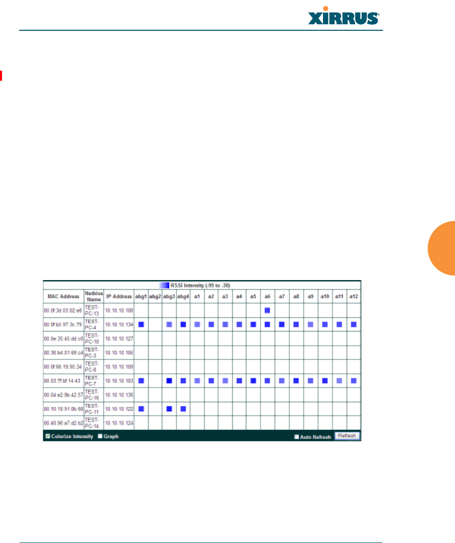
Wi-Fi Array
Viewing Status on the Wi-Fi Array 153
Working with the Custom Image
After you have uploaded a custom image (see Custom Image and Upload in
“Controls and items displayed on the Location Map window” on page 150), you
should move the display of the Array on your map to correspond with its actual
location at your site.
To move the Array on the map, simply click it, then drag and drop it to the
desired location. The Array will continue to follow the mouse pointer to allow
you to make further changes to its location. When you are satisfied with its
location, click the Array again to return to normal operation.
RSSI
For each station that is associated to the Array, the RSSI (Received Signal Strength
Indicator) window shows the station’s RSSI value as measured by each IAP. In
other words, the window shows the strength of the station’s signal at each radio.
You may choose to display Unassociated Stations as well with a checkbox at the
bottom of the window.
Figure 68. Station RSSI Values
By default, the RSSI is displayed numerically. You may display the relative
strength using color if you select Colorize Intensity, with the strongest signals
indicated by the most intense color. (Figure 68) If you select Graph, then the RSSI
is shown on a representation of the Array, either colorized or numerically based
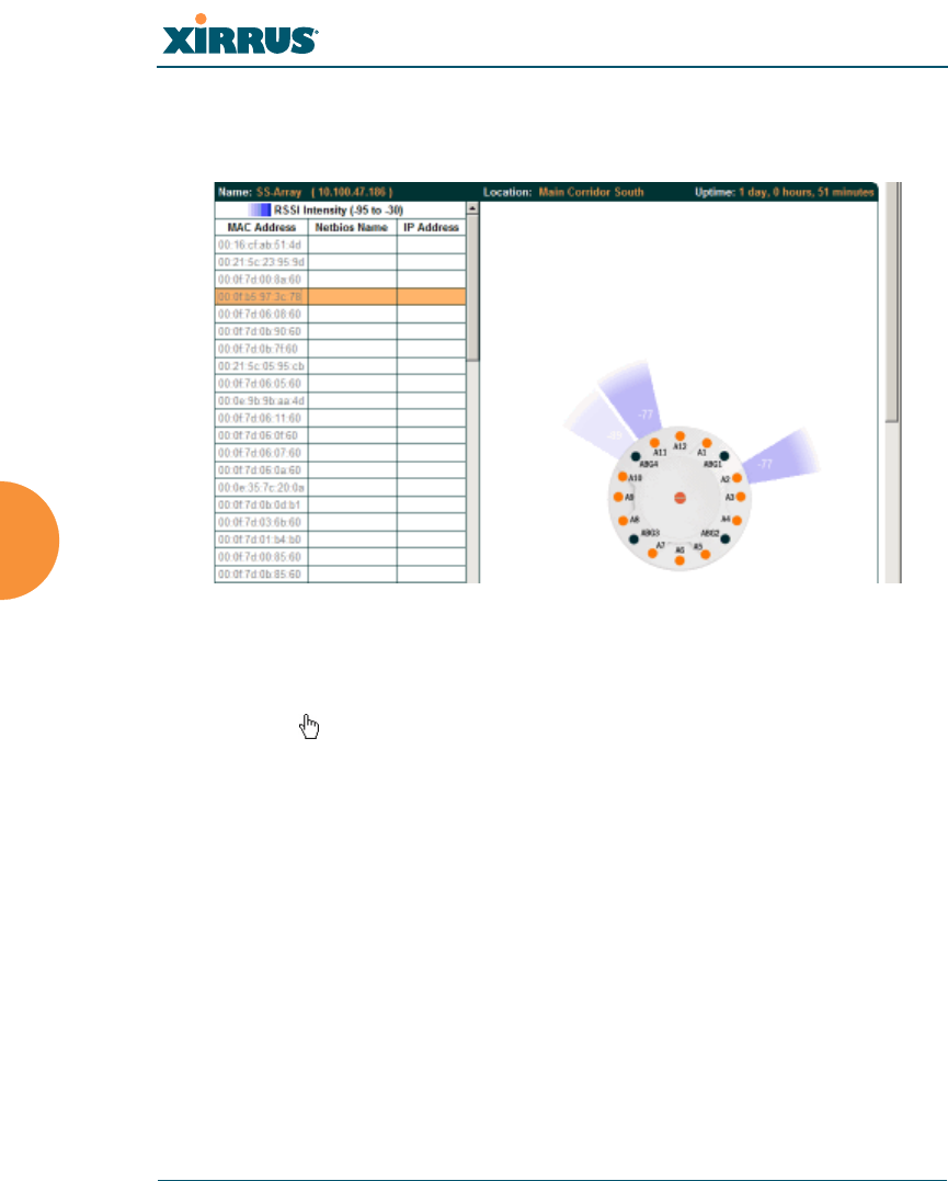
Wi-Fi Array
154 Viewing Status on the Wi-Fi Array
on your selection. (Figure 69) The stations are listed to the left of the Array — click
on a station to show its RSSI values on the Array.
Figure 69. Station RSSI Values — Colorized Graphical View
In either graphical or tabular view, you may sort the rows based on any column
that has an active column header, indicated when the mouse pointer changes to
the hand icon . Click on the Refresh button to refresh the station list, or click in
the Auto Refresh check box to instruct the Array to refresh this window
automatically.
See Also
Station Status Windows
RF Monitor Windows
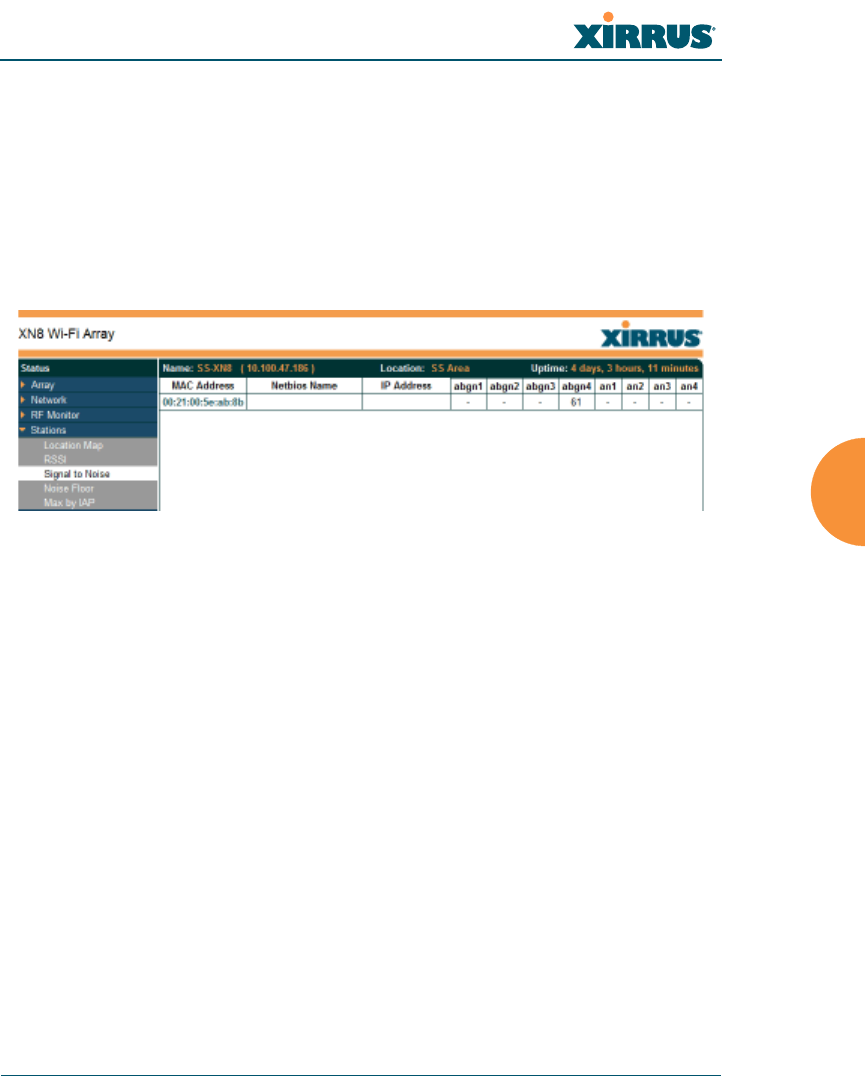
Wi-Fi Array
Viewing Status on the Wi-Fi Array 155
Signal-to-Noise Ratio (SNR)
For each station that is associated to the Array, the Signal-to-Noise Ratio (SNR)
window shows the station’s SNR value as measured by each IAP. In other words,
the window shows the SNR of the station’s signal at each IAP radio. The signal-
to-noise ratio can be very useful for determining the cause of poor performance at
a station. A low value means that action may need to be taken to reduce sources of
noise in the environment and/or improve the signal from the station.
Figure 70. Station Signal-to-Noise Ratio Values
You may choose to display Unassociated Stations as well with a checkbox at the
bottom of the window.
By default, the SNR is displayed numerically. (Figure 70) You may display
the relative value using color if you select Colorize Intensity, with the highest
SNR indicated by the most intense color. (Figure 71) If you select Graph, then
the SNR is shown on a representation of the Array, either colorized or numerically
based on your selection. The stations are listed to the left of the Array — click on a
station to show its SNR values on the Array.
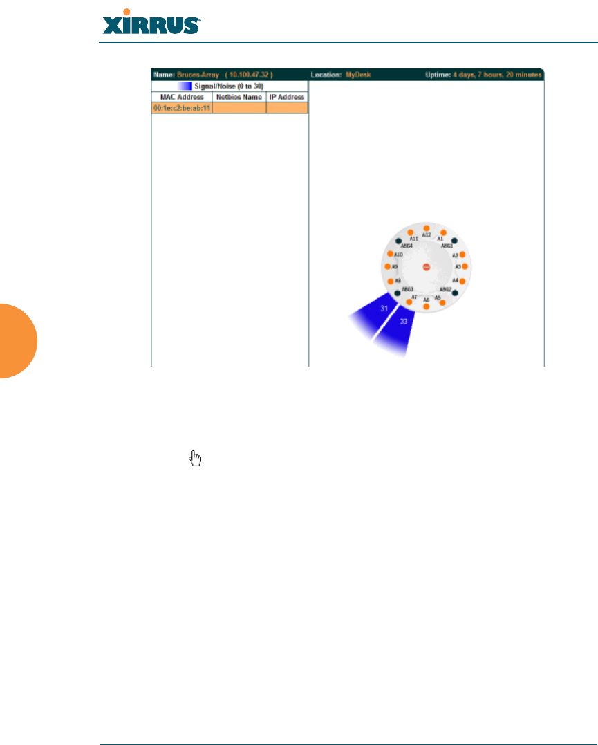
Wi-Fi Array
156 Viewing Status on the Wi-Fi Array
Figure 71. Station SNR Values — Colorized Graphical View
In either graphical or tabular view, you may sort the rows based on any column
that has an active column header, indicated when the mouse pointer changes to
the hand icon . Click on the Refresh button to refresh the station list, or click in
the Auto Refresh check box to instruct the Array to refresh this window
automatically.
See Also
Station Status Windows
RF Monitor Windows
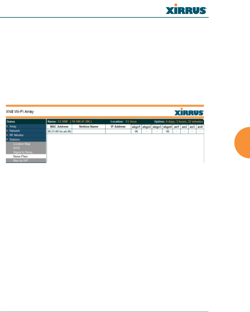
Wi-Fi Array
Viewing Status on the Wi-Fi Array 157
Noise Floor
For each station that is associated to the Array, the Noise Floor window shows
the ambient noise affecting a station’s signal as measured by each IAP. The noise
floor is the RSSI value when the station is not transmitting, sometimes called a
Silence value. In other words, the window shows the noise floor of the station’s
signal at each IAP radio. The noise floor value can be very useful for
characterizing the environment of a station to determine the cause of poor
performance. A relatively high value means that action may need to be taken to
reduce sources of noise in the environment.
Figure 72. Station Noise Floor Values
You may choose to display Unassociated Stations as well with a checkbox at the
bottom of the window.
By default, the noise floor is displayed numerically. (Figure 72) You may display
the relative value using color if you select Colorize Intensity, with the highest
noise indicated by the most intense color. If you select Graph, then the ambient
noise is shown on a representation of the Array, either colorized or numerically
based on your selection.(Figure 73) The stations are listed to the left of the
Array — click on a station to show its values on the Array.
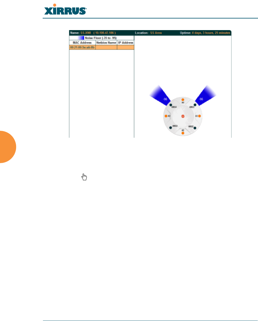
Wi-Fi Array
158 Viewing Status on the Wi-Fi Array
Figure 73. Station Noise Floor Values — Colorized Graphical View
In either graphical or tabular view, you may sort the rows based on any column
that has an active column header, indicated when the mouse pointer changes to
the hand icon . Click on the Refresh button to refresh the station list, or click in
the Auto Refresh check box to instruct the Array to refresh this window
automatically.
See Also
Station Status Windows
RF Monitor Windows
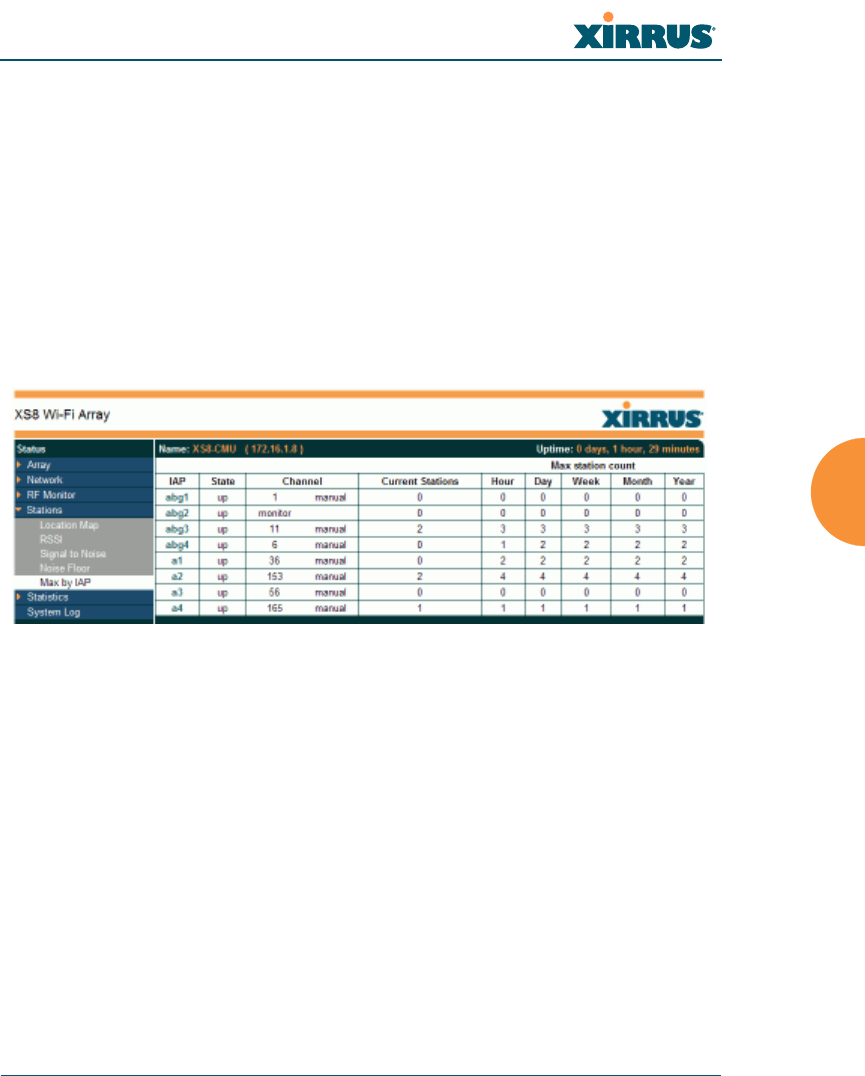
Wi-Fi Array
Viewing Status on the Wi-Fi Array 159
Max by IAP
This status-only window shows the maximum number of client stations that have
historically been associated to the Array. For each IAP, the list shows the IAP’s
state and channel number, the current number of stations associated, and the
highest number of stations that have been associated over various periods of time:
hour, day, week, month, and year. In other words, the Max Station Count shows
the “high water mark” over the selected period of time — the maximum count of
stations for the selected period, rather than a cumulative count of all stations that
have associated. This information aids in network administration and in planning
for additional capacity.
Figure 74. Max by IAP
You may click an IAP to go to the IAP Settings window. Click on the Refresh
button to refresh the station list, or click Auto Refresh to instruct the Array to
refresh this window automatically.
See Also
IAPs
Station Status Windows

Wi-Fi Array
160 Viewing Status on the Wi-Fi Array
Statistics Windows
The following Array Statistics windows are available:
IAP Statistics Summary — provides an overview of the statistical data
associated with all IAPs. Expands to show links for displaying detailed
statistics for individual IAPs.
Per-IAP Statistics — provides detailed statistics for an individual IAP.
Network Statistics — displays statistical data associated with each
network (Ethernet) interface.
VLAN Statistics — provides statistical data associated with your assigned
VLANs.
WDS Statistics — provides statistical data for all WDS client and host
links.
Filter Statistics — provides statistical data for all configured filters.
Station Statistics — provides statistical data associated with each station.
IAP Statistics Summary
This is a status only window that provides an overview of the statistical data
associated with all IAPs. It also shows the channel used by each IAP. For detailed
statistics for a specific IAP, see “Per-IAP Statistics” on page 161. Click the Unicast
Stats Only checkbox on the lower left to filter the results, or clear the checkbox to
show statistics for all wireless traffic.
You can Refresh the data (update the window with the latest information) or
Clear the data (reset all content to zero and begin counting again) at any time by
clicking on the appropriate button. You can also click in the Auto Refresh check
box to instruct the Array to refresh this window automatically.
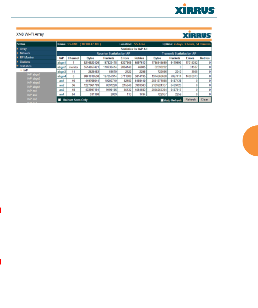
Wi-Fi Array
Viewing Status on the Wi-Fi Array 161
Figure 75. IAP Statistics Summary Page
See Also
System Log Window
Global Settings (IAP)
Global Settings .11a
Global Settings .11bg
IAPs
Per-IAP Statistics
This is a status only window that provides detailed statistics for the selected IAP.
If you click the link for IAP All in the left frame, each detailed statistic field will
show the sum of that statistic for all IAPs. For a summary of statistics for all IAPs,
see “IAP Statistics Summary” on page 160. Use the Display Percentages
checkbox at the lower left to select the output format — check this option to
express each statistic as a percentage of the total at the top of the column, or leave
it blank to display raw numbers.
A quick way to display the statistics for a particular IAP is by clicking the Array
graphic at the bottom left of the WMI window. Click the desired IAP, and the
selected statistics will be displayed. See “User Interface” on page 117.
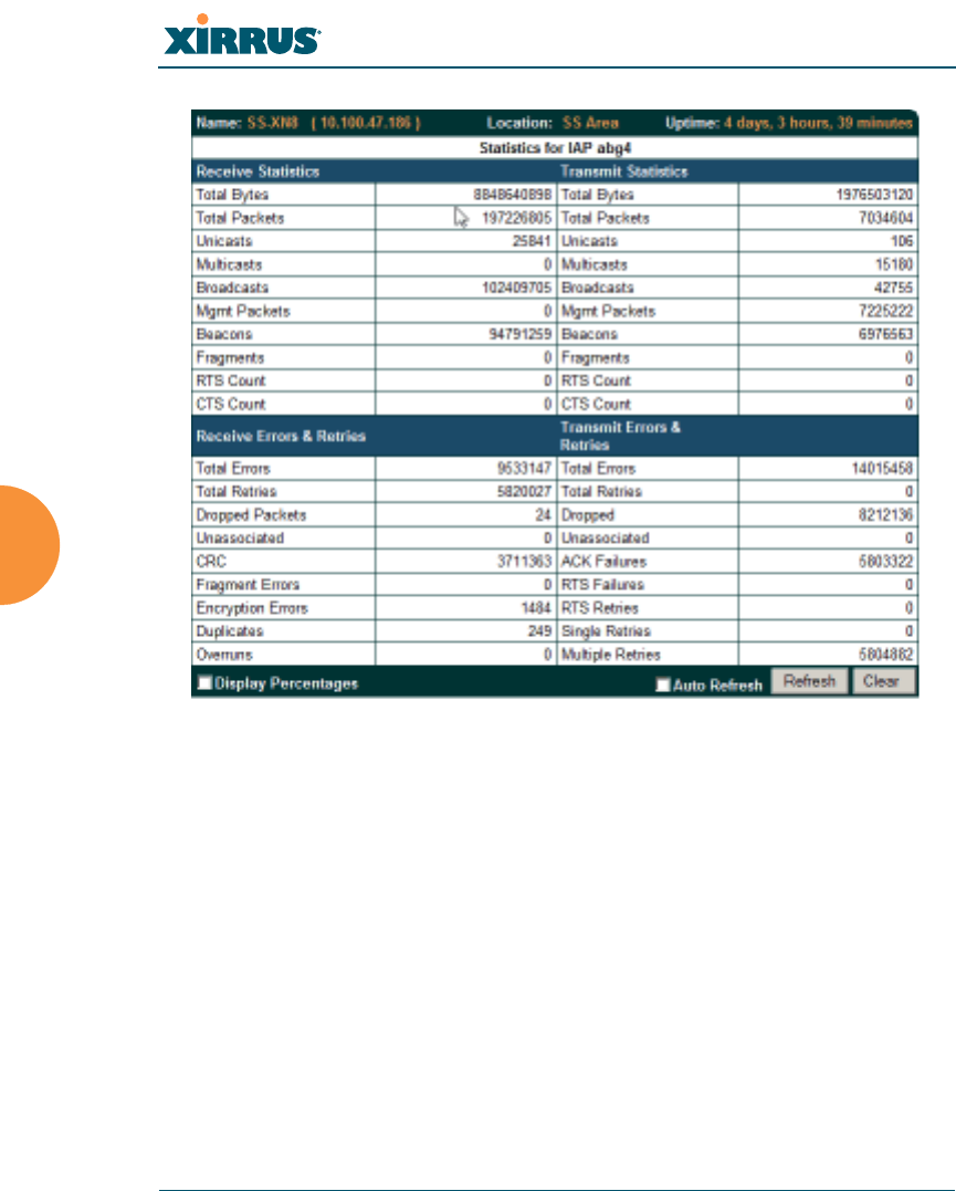
Wi-Fi Array
162 Viewing Status on the Wi-Fi Array
Figure 76. Individual IAP Statistics Page (for IAP abg(n)1)
You can Refresh the data (update the window with the latest information) or
Clear the data (reset all content to zero and begin counting again) at any time by
clicking on the appropriate button. You can also click in the Auto Refresh check
box to instruct the Array to refresh this window automatically.
See Also
System Log Window
Global Settings (IAP)
Global Settings .11a
Global Settings .11bg
IAPs
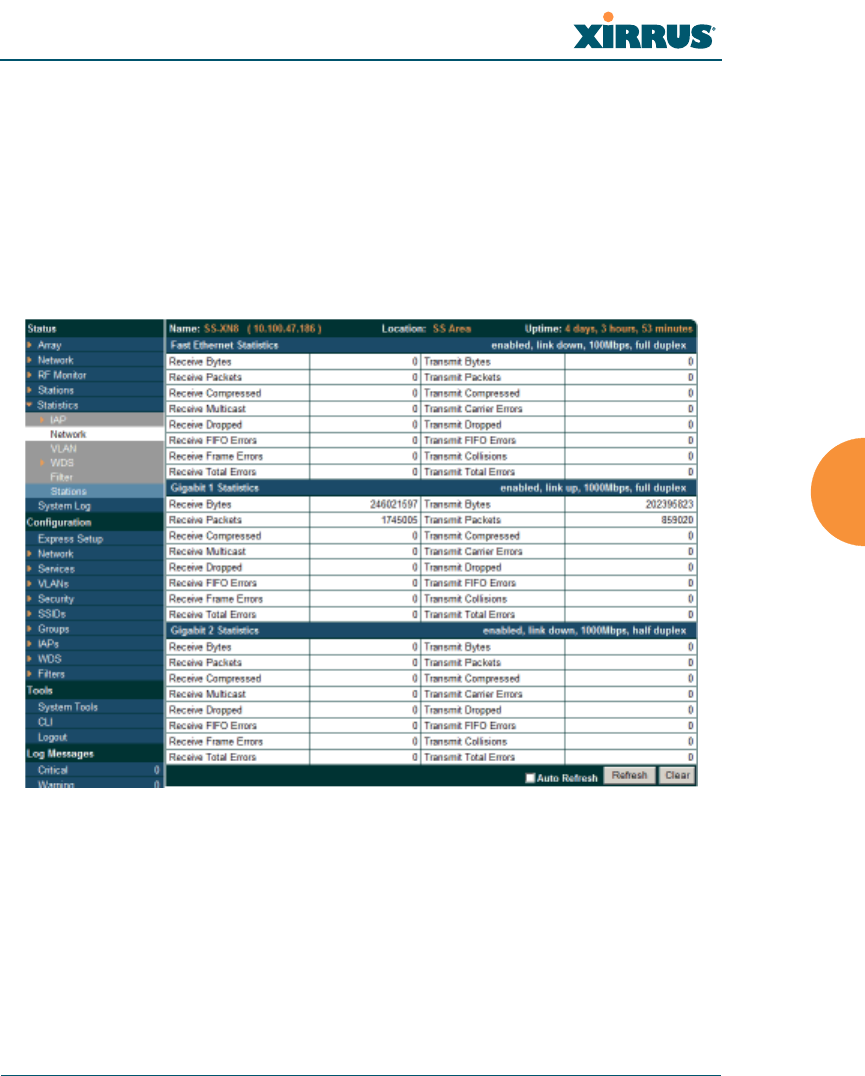
Wi-Fi Array
Viewing Status on the Wi-Fi Array 163
Network Statistics
This is a status only window that allows you to review statistical data associated
with each network (Ethernet) interface and its activity. You can Refresh the data
(update the window with the latest information) or Clear the data (reset all
content to zero and begin counting again) at any time by clicking on the
appropriate button. You can also click in the Auto Refresh check box to instruct
the Array to refresh this window automatically. If you are experiencing problems
on the Array, you may also want to print this window for your records.
Figure 77. Network Statistics
See Also
DHCP Server
DNS Settings
Network
Network Interfaces
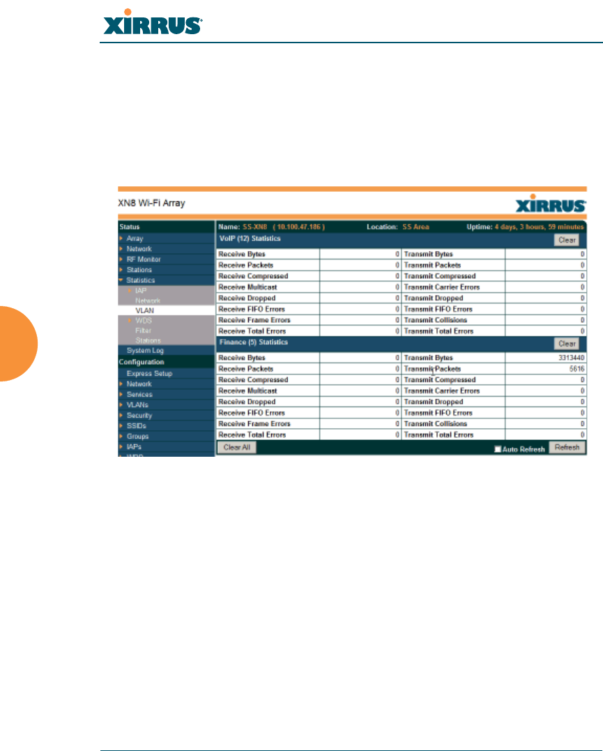
Wi-Fi Array
164 Viewing Status on the Wi-Fi Array
VLAN Statistics
This is a status only window that allows you to review statistical data associated
with your assigned VLANs. You can refresh the information that is displayed on
this page at any time by clicking on the Refresh button, or select the Auto Refresh
option for this window to refresh automatically. The Clear All button at the lower
left allows you to clear (zero out) all VLAN statistics.
Figure 78. VLAN Statistics
See Also
VLAN Management
VLANs
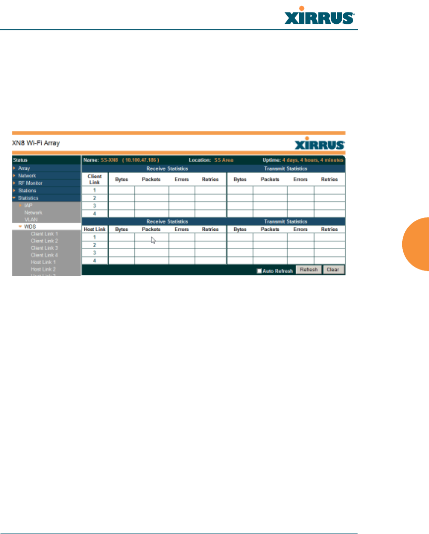
Wi-Fi Array
Viewing Status on the Wi-Fi Array 165
WDS Statistics
The main WDS Statistics window provides statistical data for all WDS client and
host links. To access data about a specific WDS client or host link, simply click on
the desired link in the left frame to access the appropriate window. You may also
choose to view a sum of the statistics for all client links, all host links, or all links
(both client and host links).
Figure 79. WDS Statistics
See Also
SSID Management
WDS
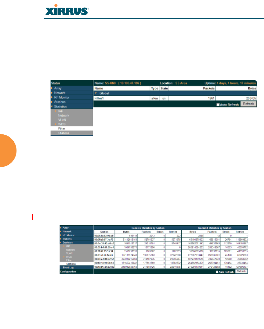
Wi-Fi Array
166 Viewing Status on the Wi-Fi Array
Filter Statistics
The Filter Statistics window provides statistical data for all configured filters. The
name, state (enabled — on or off), and type (allow or deny) of each filter is shown.
For enabled filters, this window shows the number of packets and bytes that met
the filter criteria. Click on a column header to sort the rows based on that column.
Click on a filter name to edit the filter settings.
Figure 80. Filter Statistics
See Also
Filters
Station Statistics
This status-only window provides an overview of statistical data for all stations.
Stations are listed by MAC address, and Receive and Transmit statistics are
summarized for each. For detailed statistics for a specific station, click the desired
MAC address in the Station column and see “Per-Station Statistics” on page 167.
Figure 81. Station Statistics
Note that you can clear the data for an individual station (see Per-Station
Statistics), but you cannot clear the data for all stations using this window.
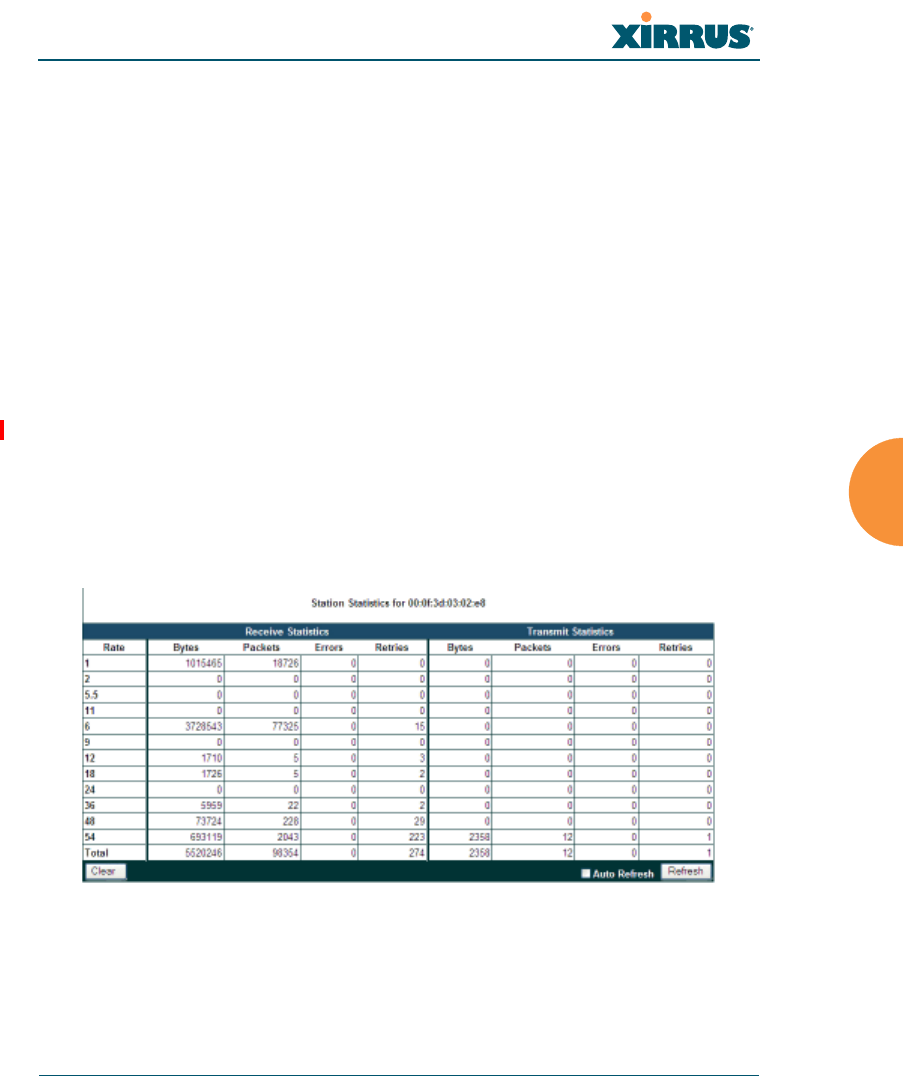
Wi-Fi Array
Viewing Status on the Wi-Fi Array 167
You can Refresh the data (update the window with the latest information) at any
time by clicking on the appropriate button. You can also click in the Auto Refresh
check box to instruct the Array to refresh this window automatically.
See Also
Per-Station Statistics
Per-Station Statistics
This window provides detailed statistics for the selected station. This window is
accessed from the Station Statistics window — click the MAC address of the
desired entry in the Station column to display its Per-Station Statistics window.
Receive and Transmit statistics are listed by Rate — this is the data rate in Mbps.
For a summary of statistics for all stations, see “Station Statistics” on page 166.
You can Refresh the data (update the window with the latest information) or
Clear the data (reset all content to zero and begin counting again) at any time by
clicking on the appropriate button. You can also click in the Auto Refresh check
box to instruct the Array to refresh this window automatically.
Figure 82. Individual Station Statistics Page
See Also
Station Statistics
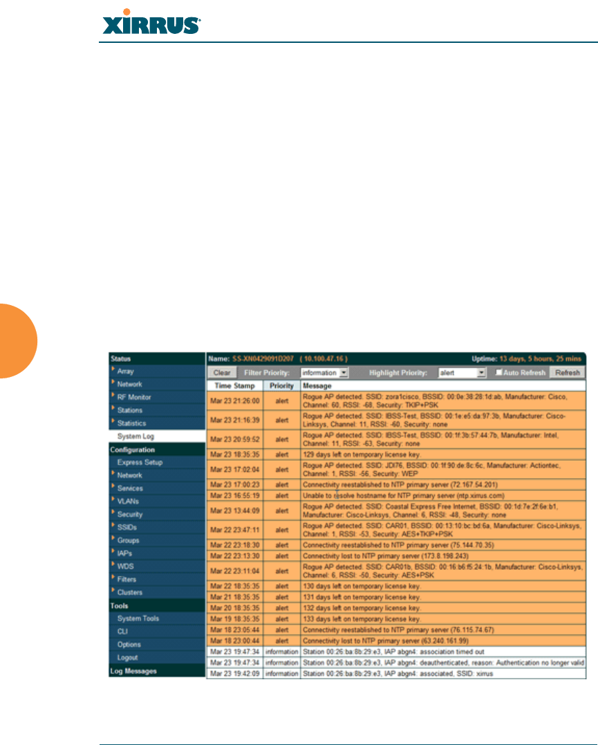
Wi-Fi Array
168 Viewing Status on the Wi-Fi Array
System Log Window
This is a status only window that allows you to review the system log, where
system alerts and messages are displayed. Although there are no configuration
options available in this window, you do have the usual choice of deciding how
the event messages are sorted by clicking in the column header for the desired
field (Time Stamp, Priority, or Message).
Time Stamp — sorts the list based on the time the event occurred.
Priority — sorts the list based on the priority assigned to the message.
Message — sorts the list based on the message category
The displayed messages may be filtered by using the Filter Priority option, which
allows control of the minimum priority level displayed. For example, you may
choose (under Services >System Log) to log messages at or above Debug level
but use Filter Priority to display only those at Information level and above.
Figure 83. System Log

Wi-Fi Array
Viewing Status on the Wi-Fi Array 169
Use the Highlight Priority field if you wish to highlight messages at the selected
priority level. Click on the Refresh button to refresh the message list, or click on
the Clear button at the upper left to delete all messages. You can also click in the
Auto Refresh check box to instruct the Array to refresh this window
automatically.
Note that there is a shortcut way to view system log messages. If you click Log
Messages near the bottom of the left hand frame, WMI displays counts of log
messages at different severity levels. Click a count to display just those messages
in the System Log window. SeeFigure 42 on page 117 for more information.

Wi-Fi Array
170 Viewing Status on the Wi-Fi Array