Cambium Networks XN4 Wireless LAN Array User Manual xirrus PDF

Xirrus, Inc. Wireless LAN Array xirrus PDF

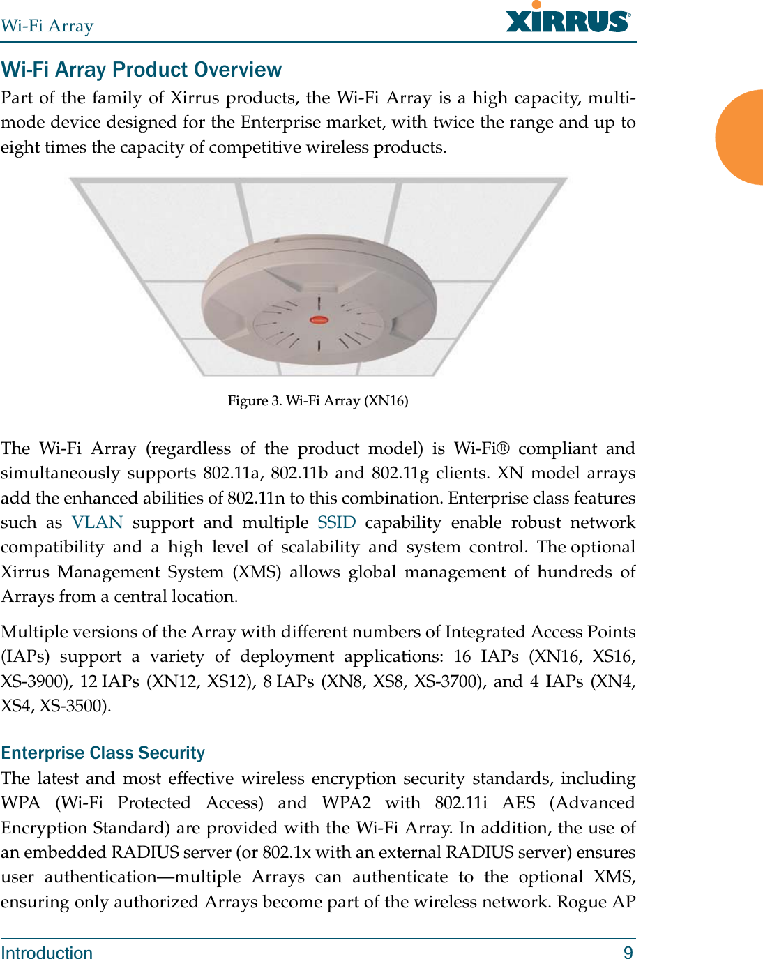
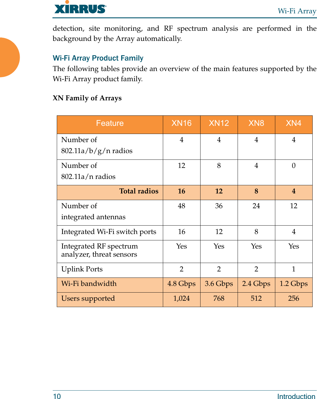
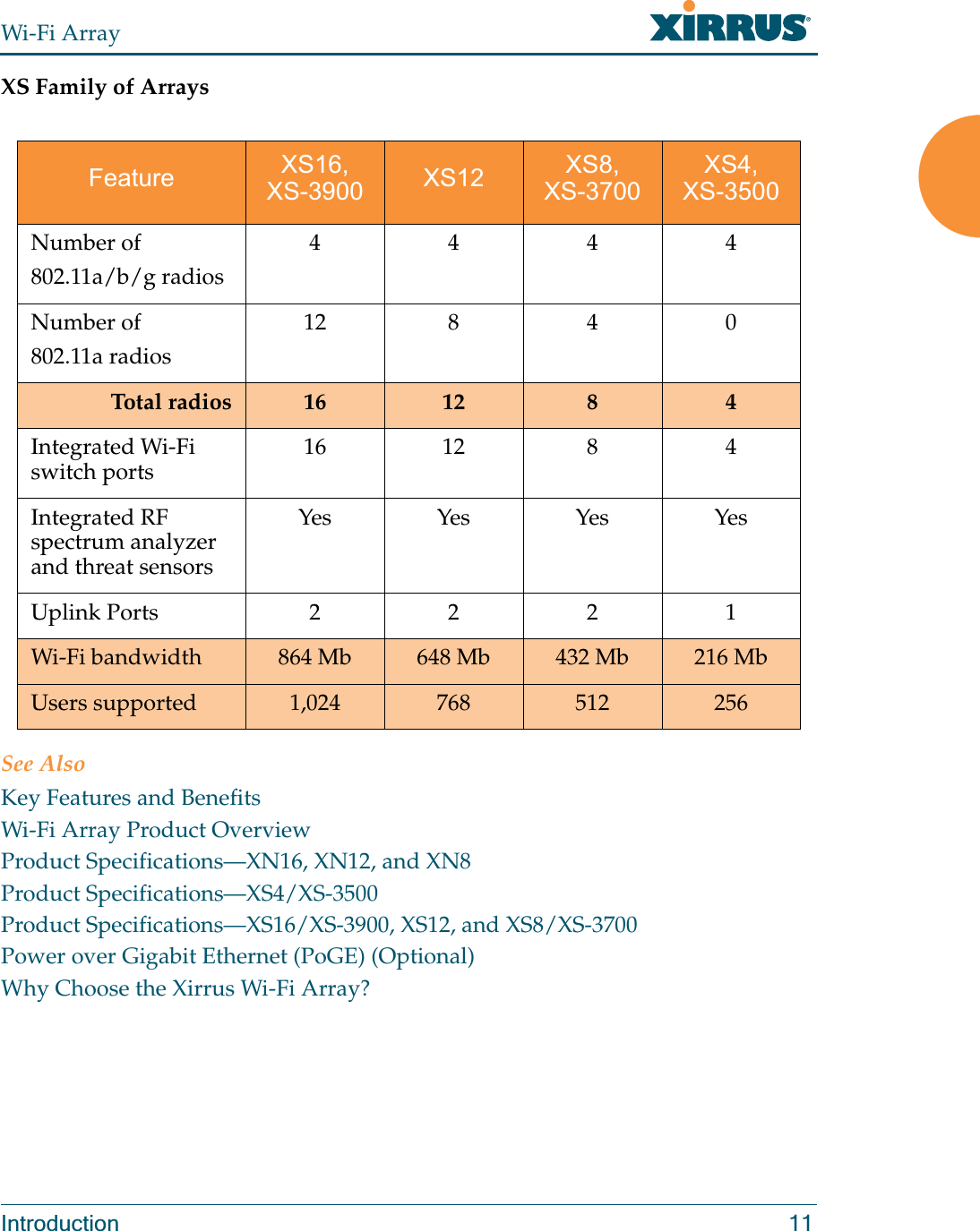
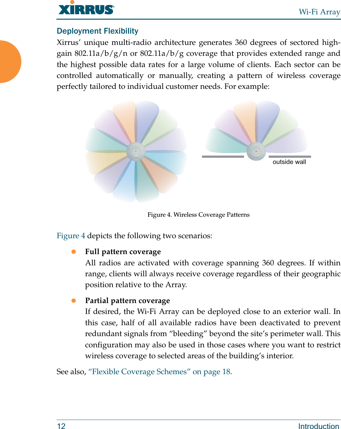
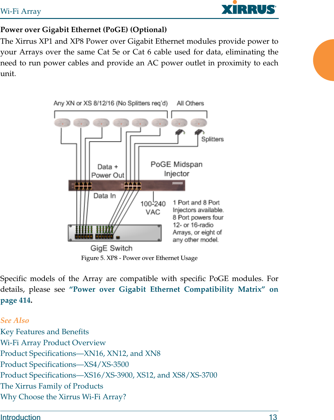
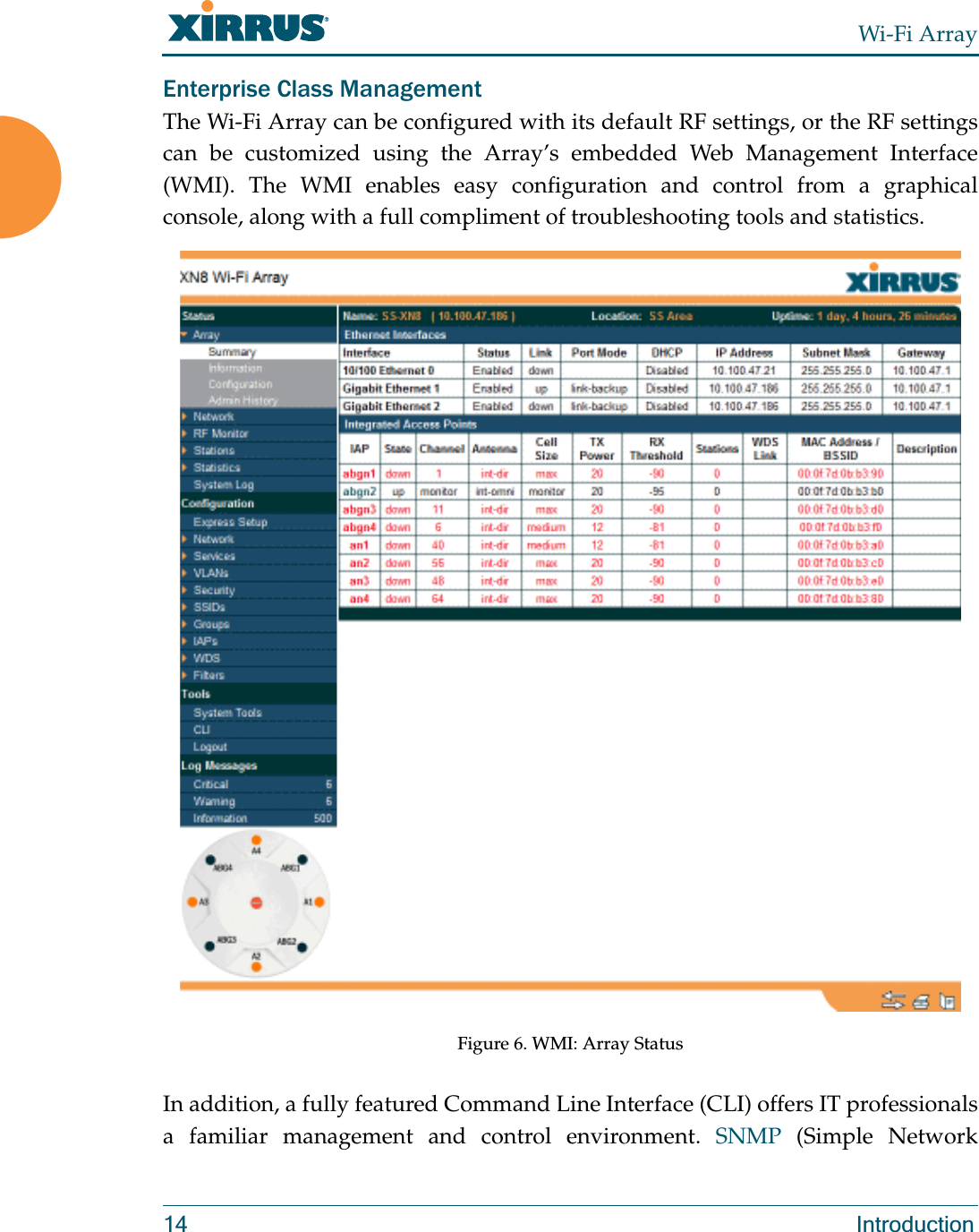
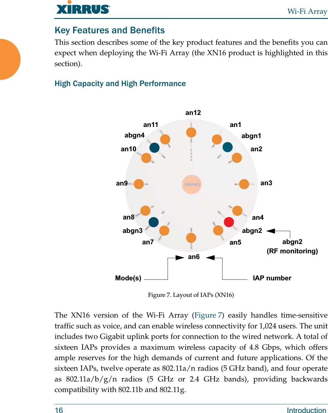
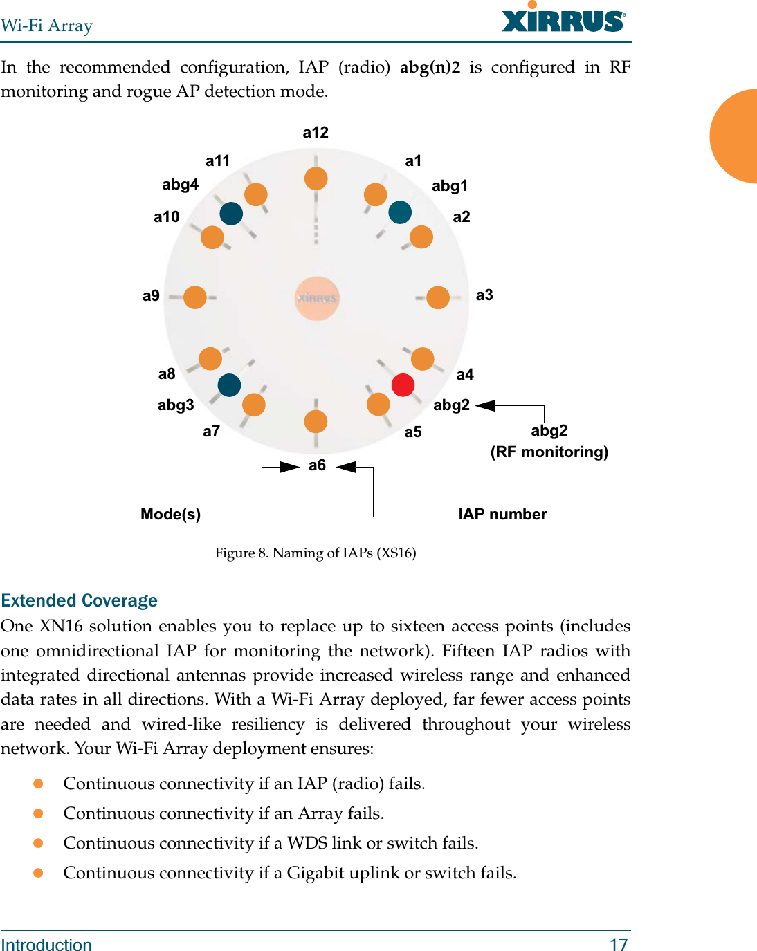
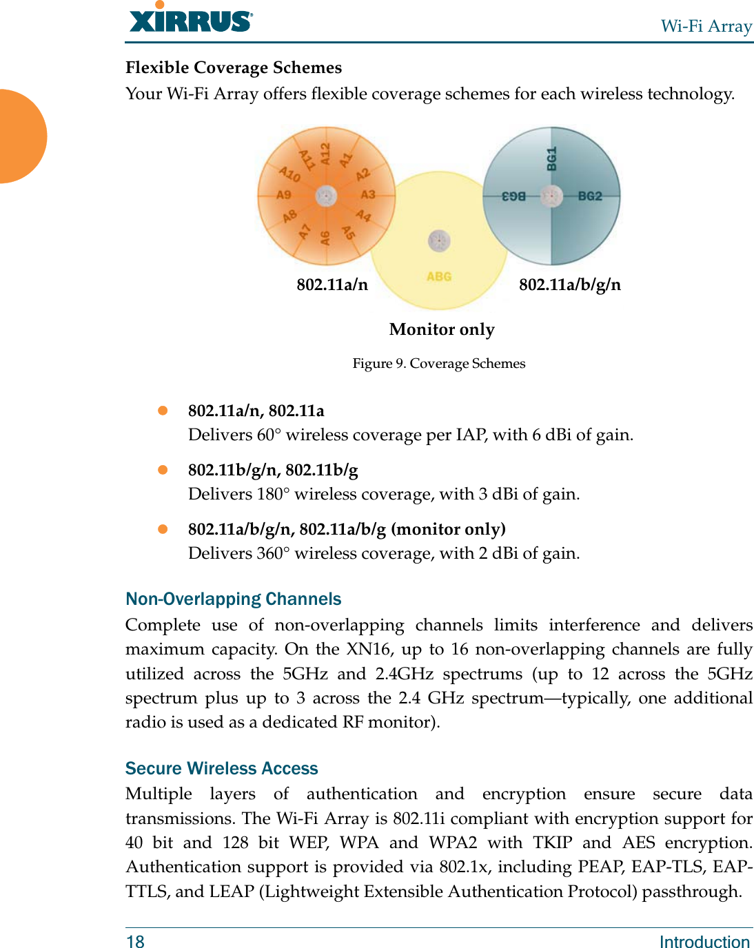
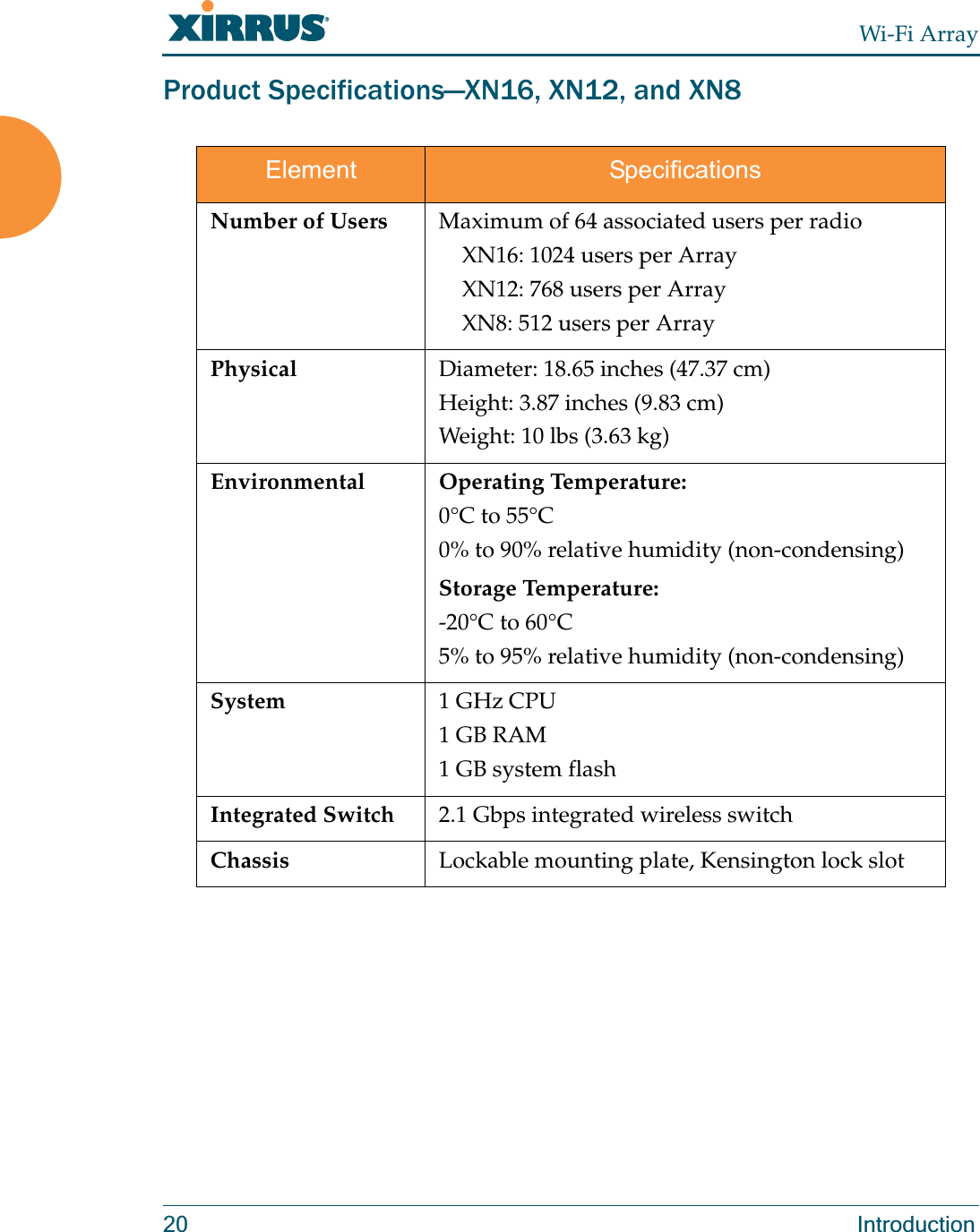
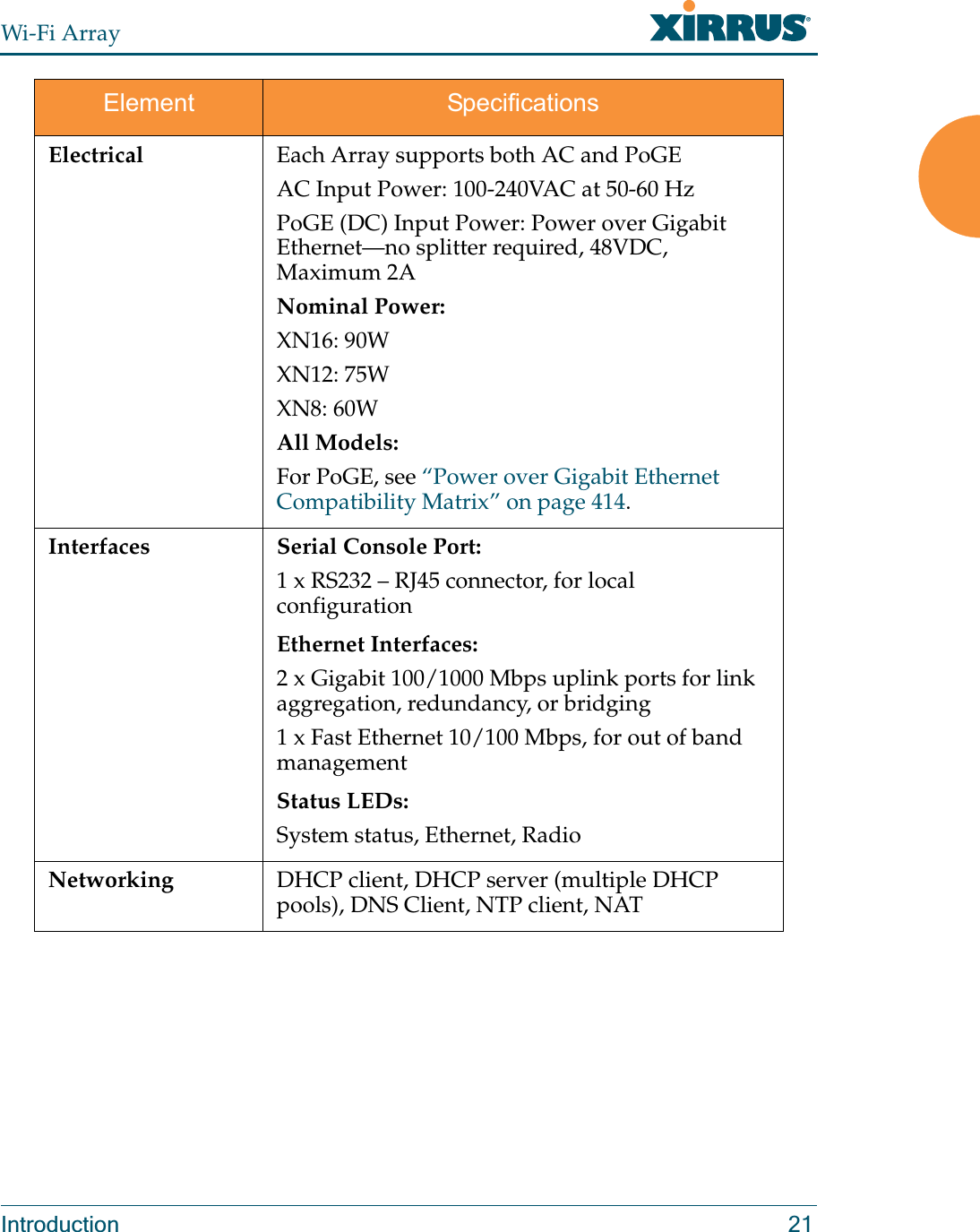
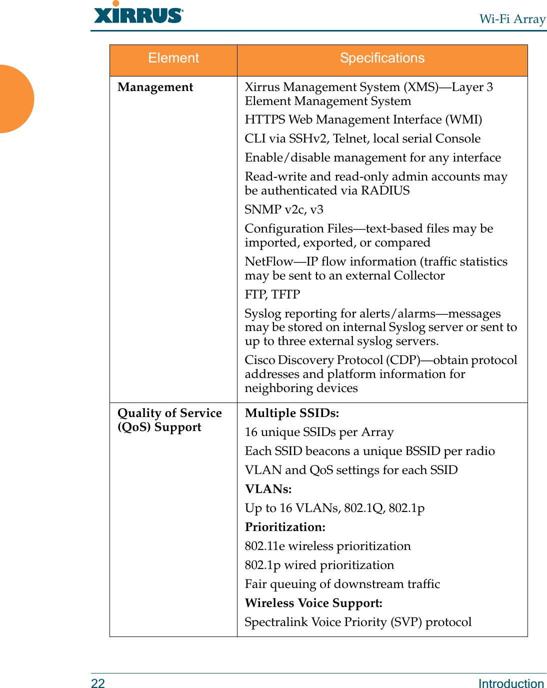
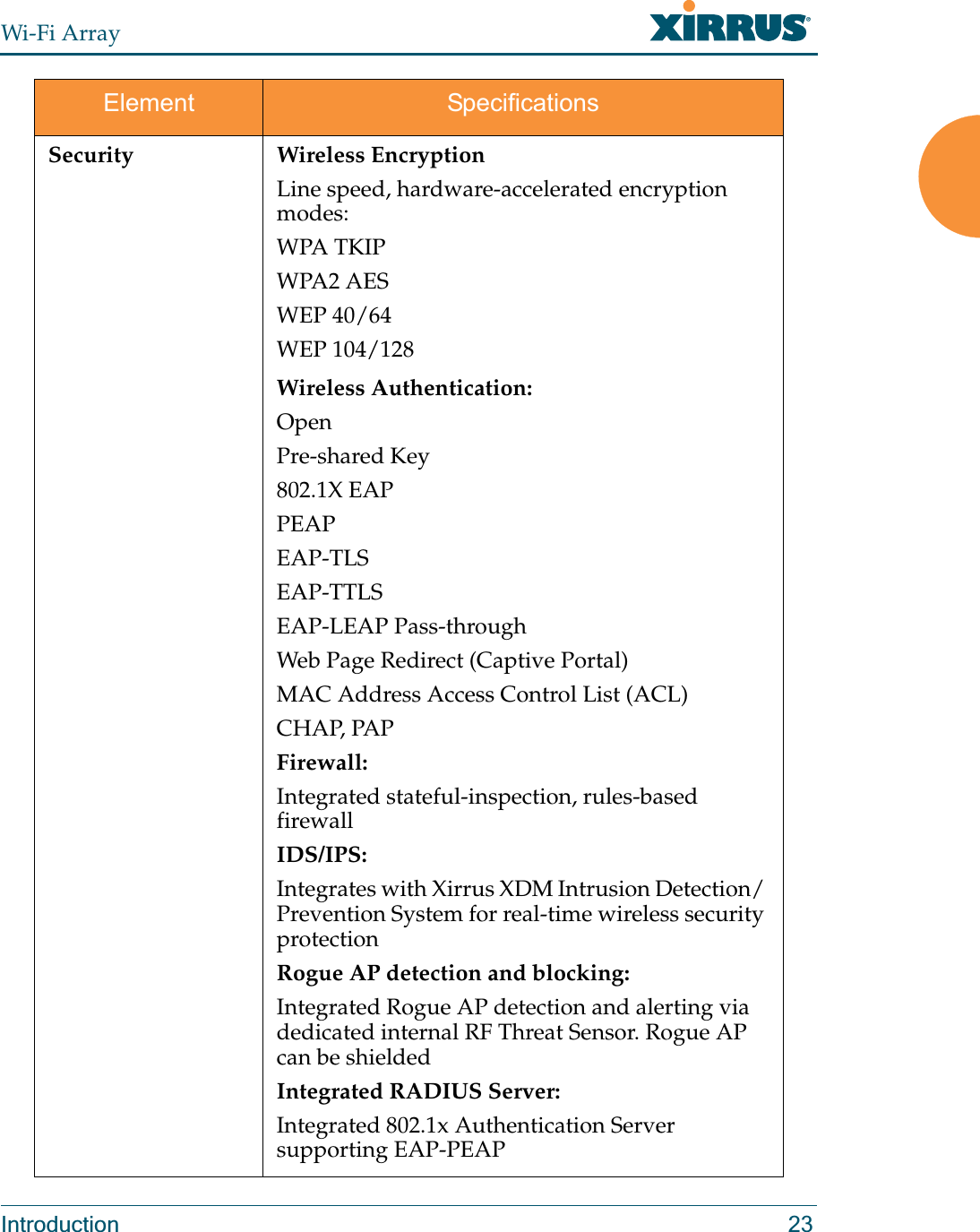
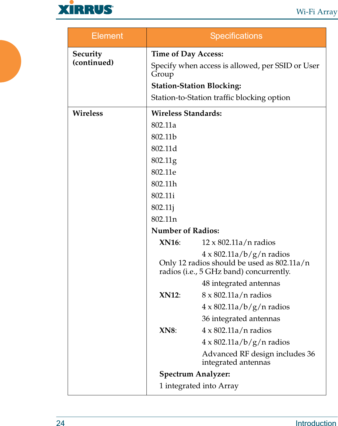
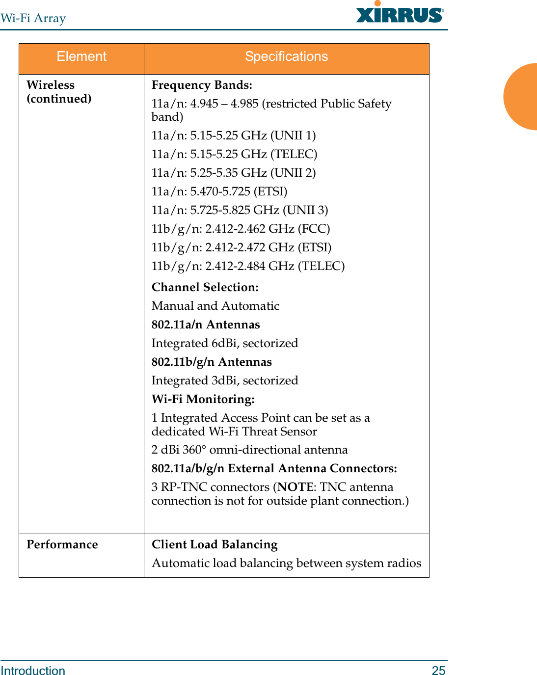
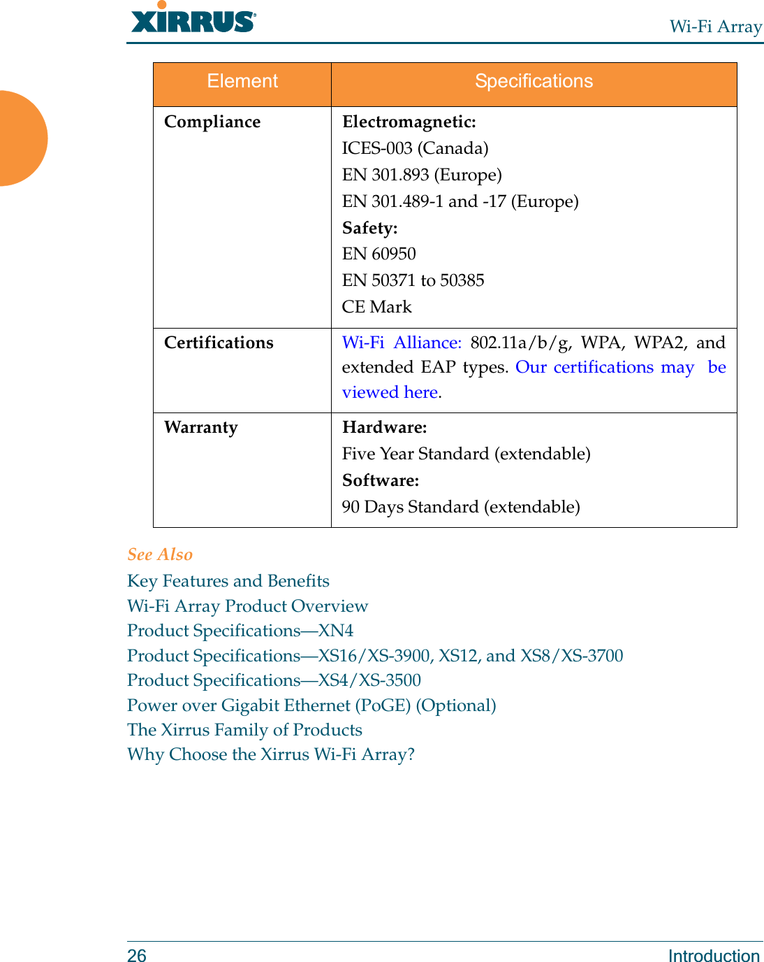
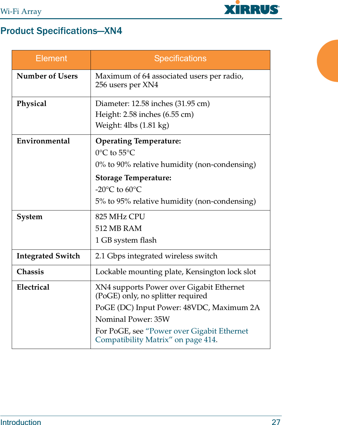
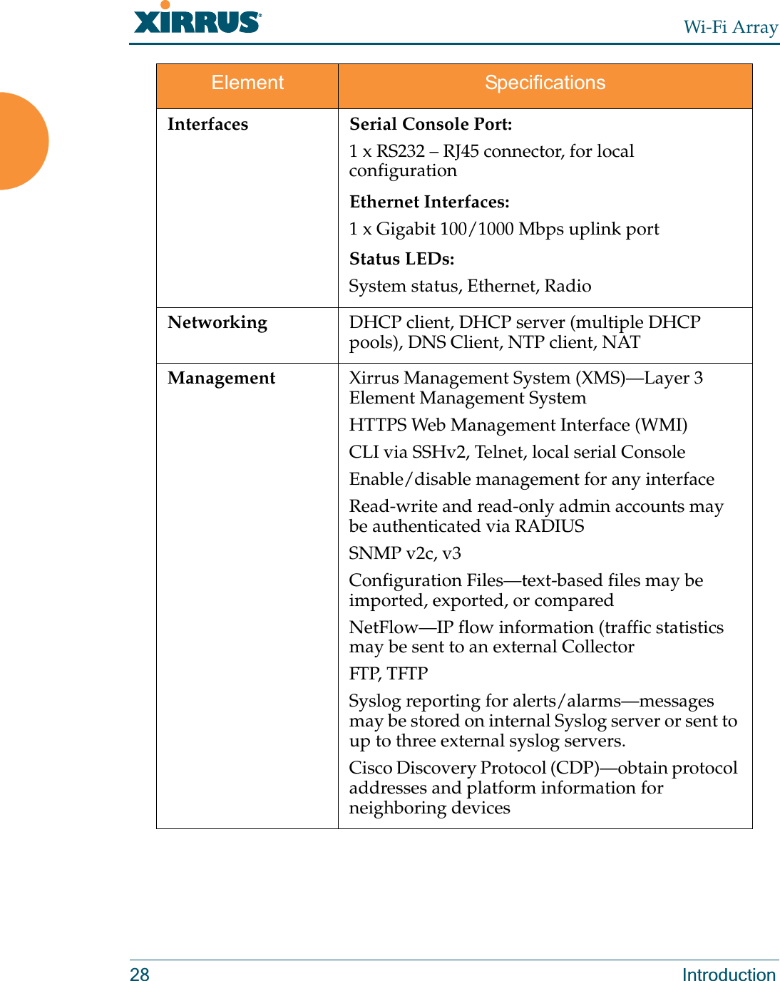
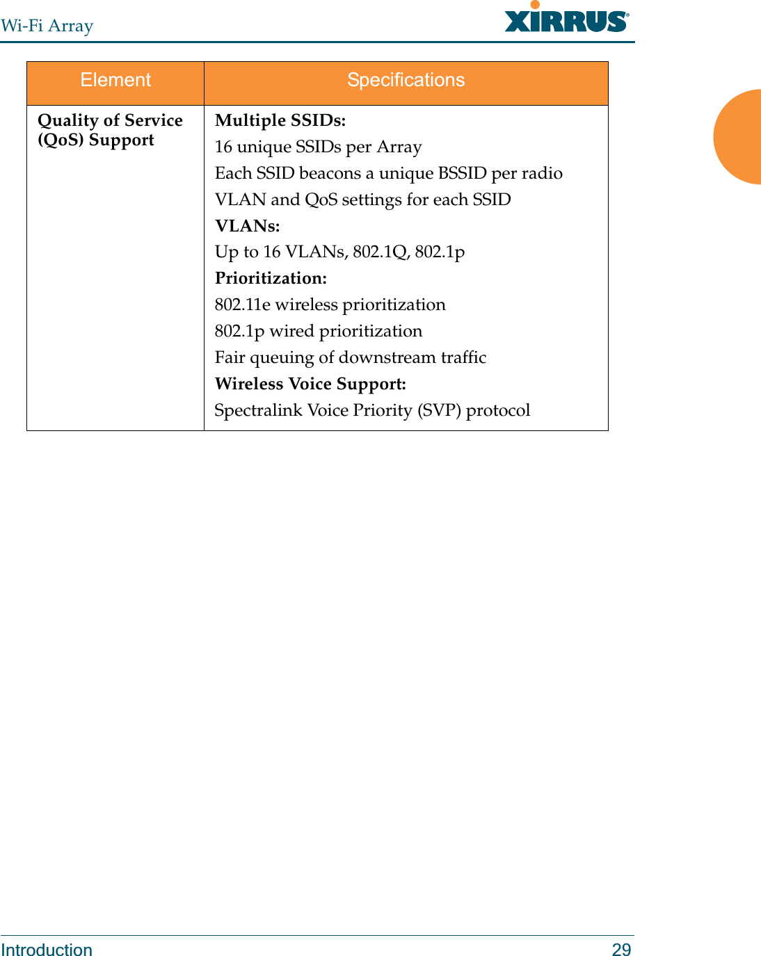
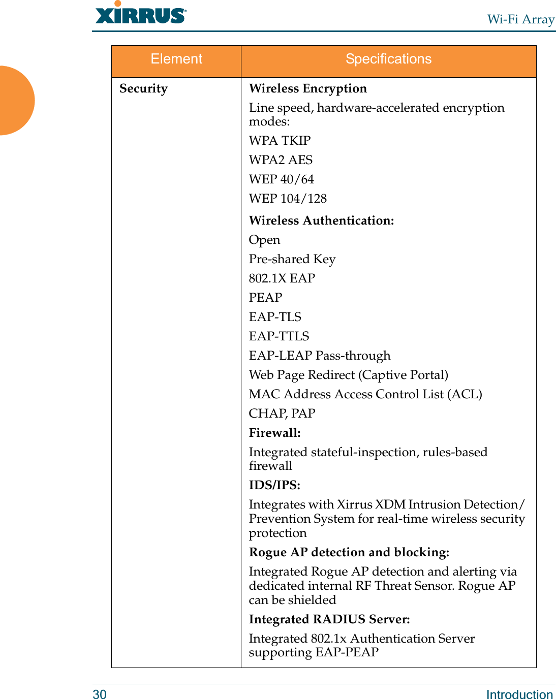
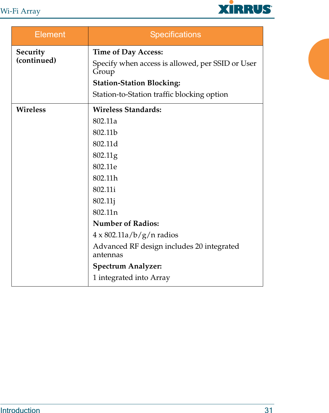
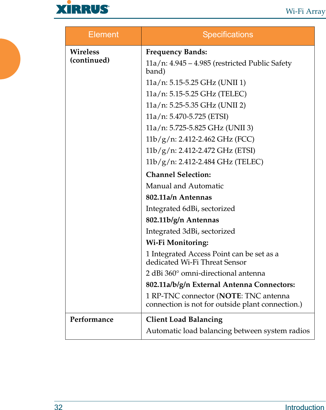
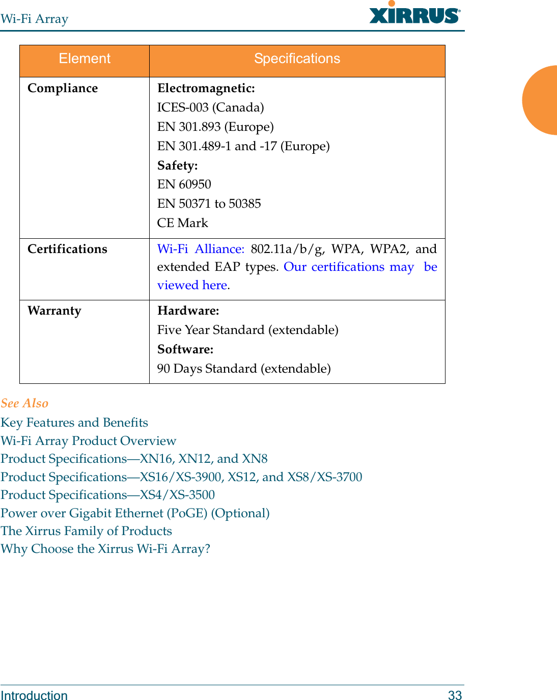
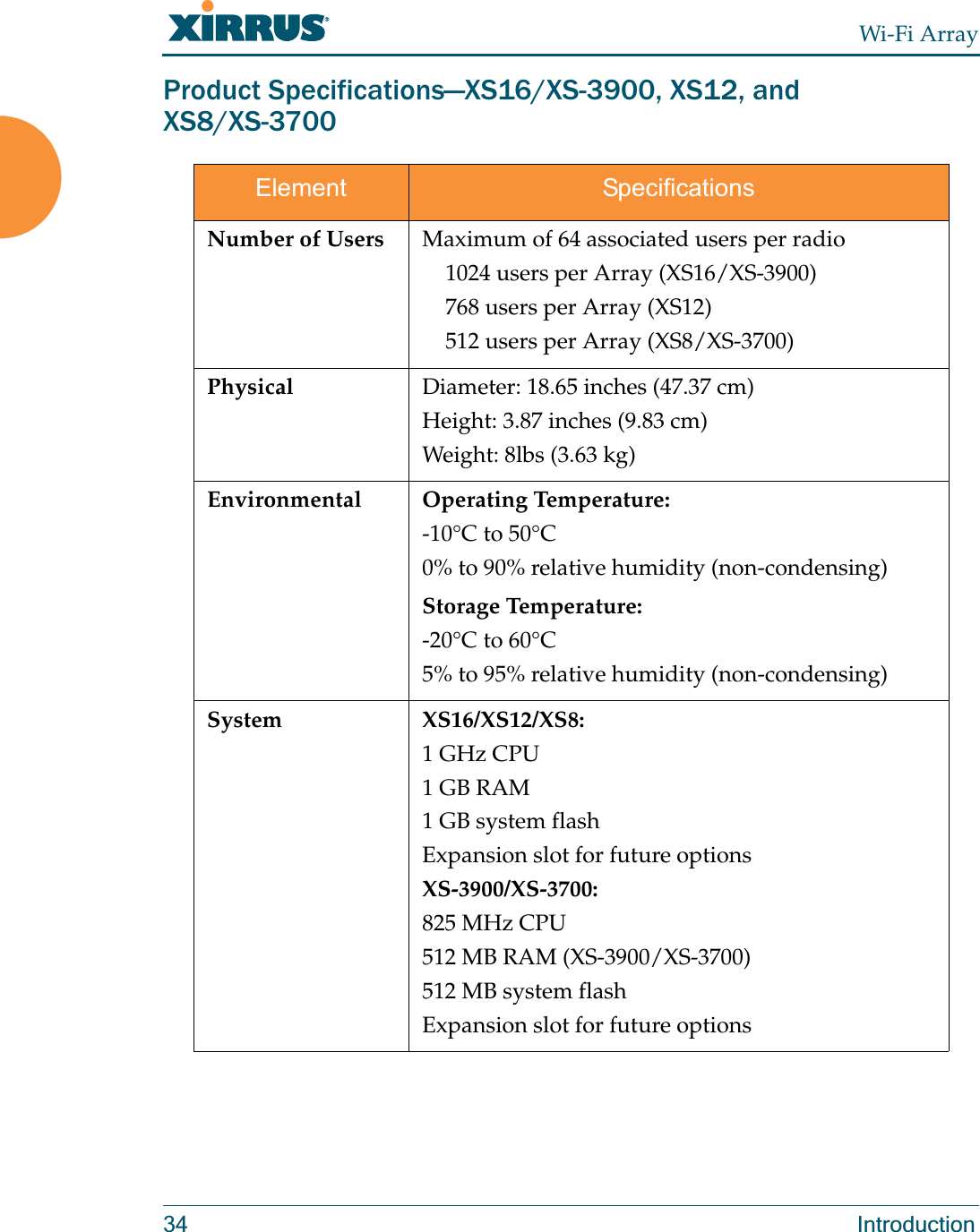
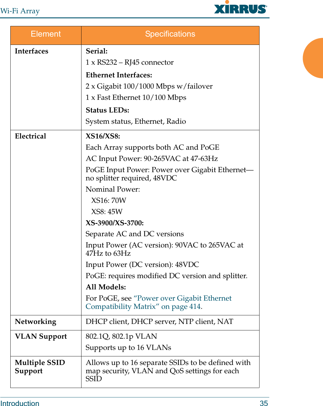
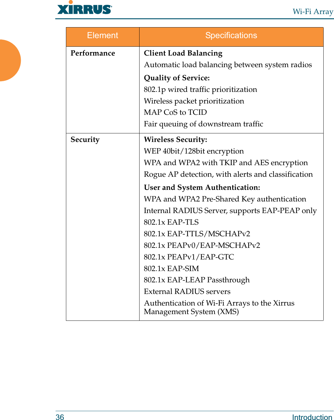
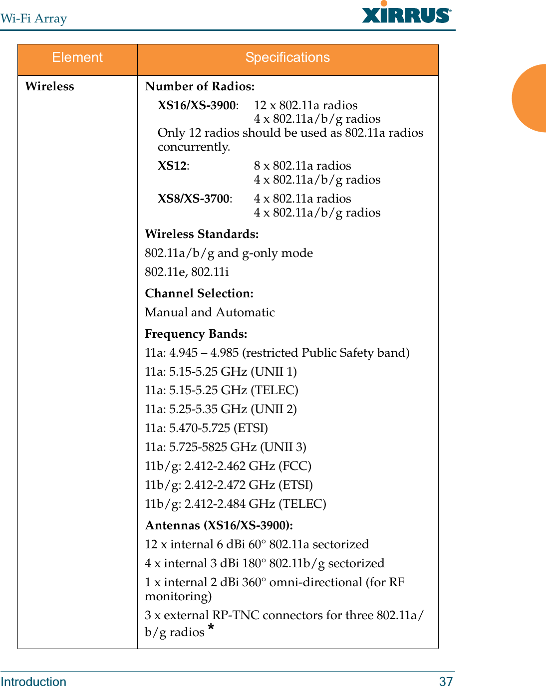
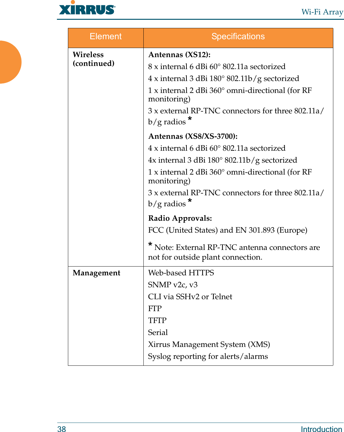
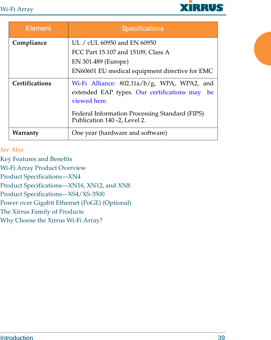
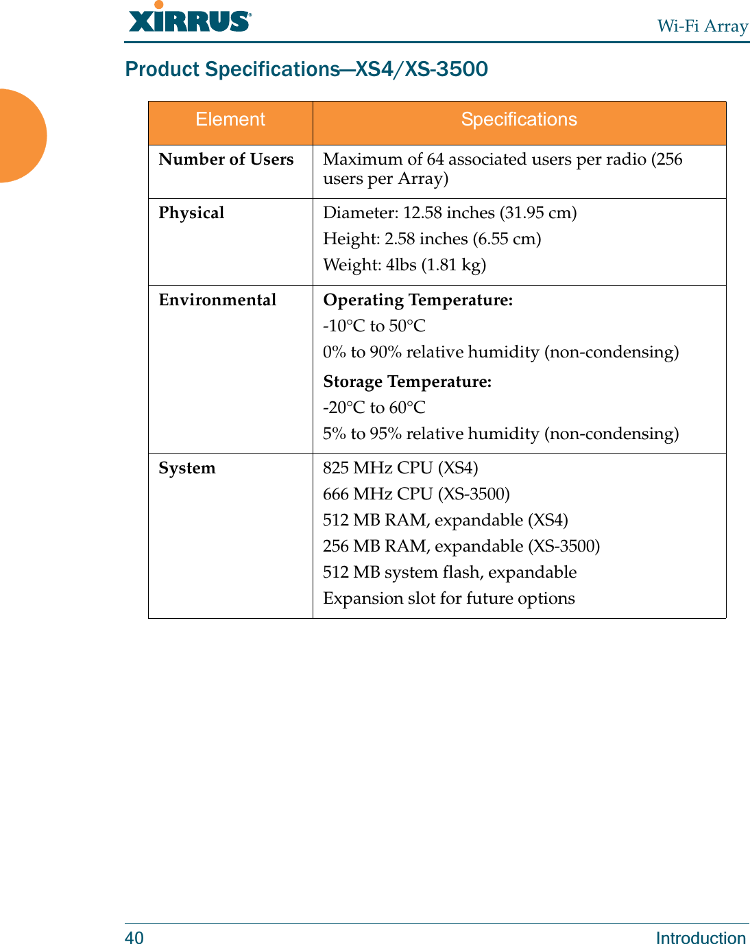
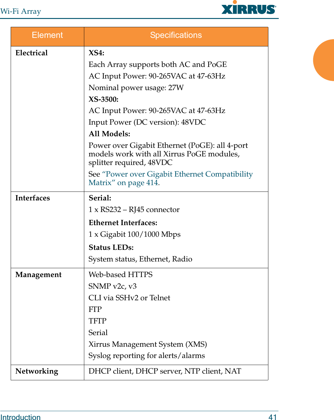
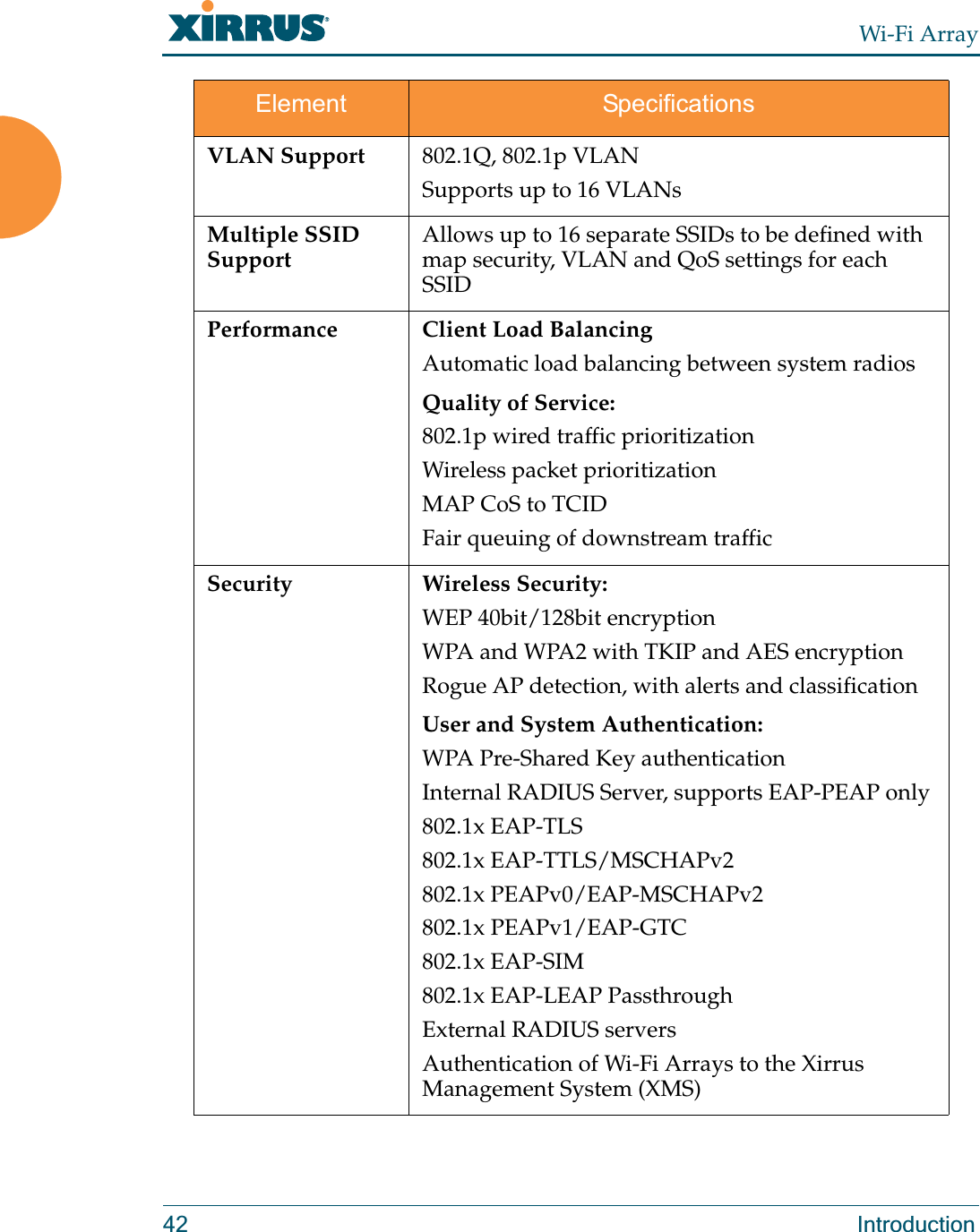
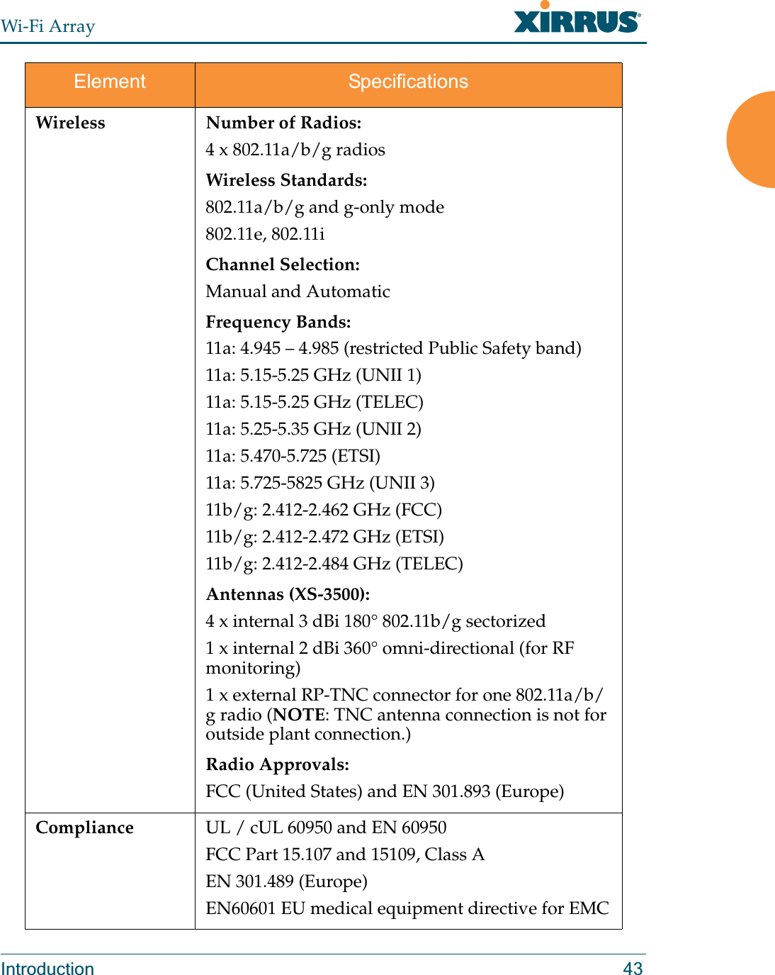
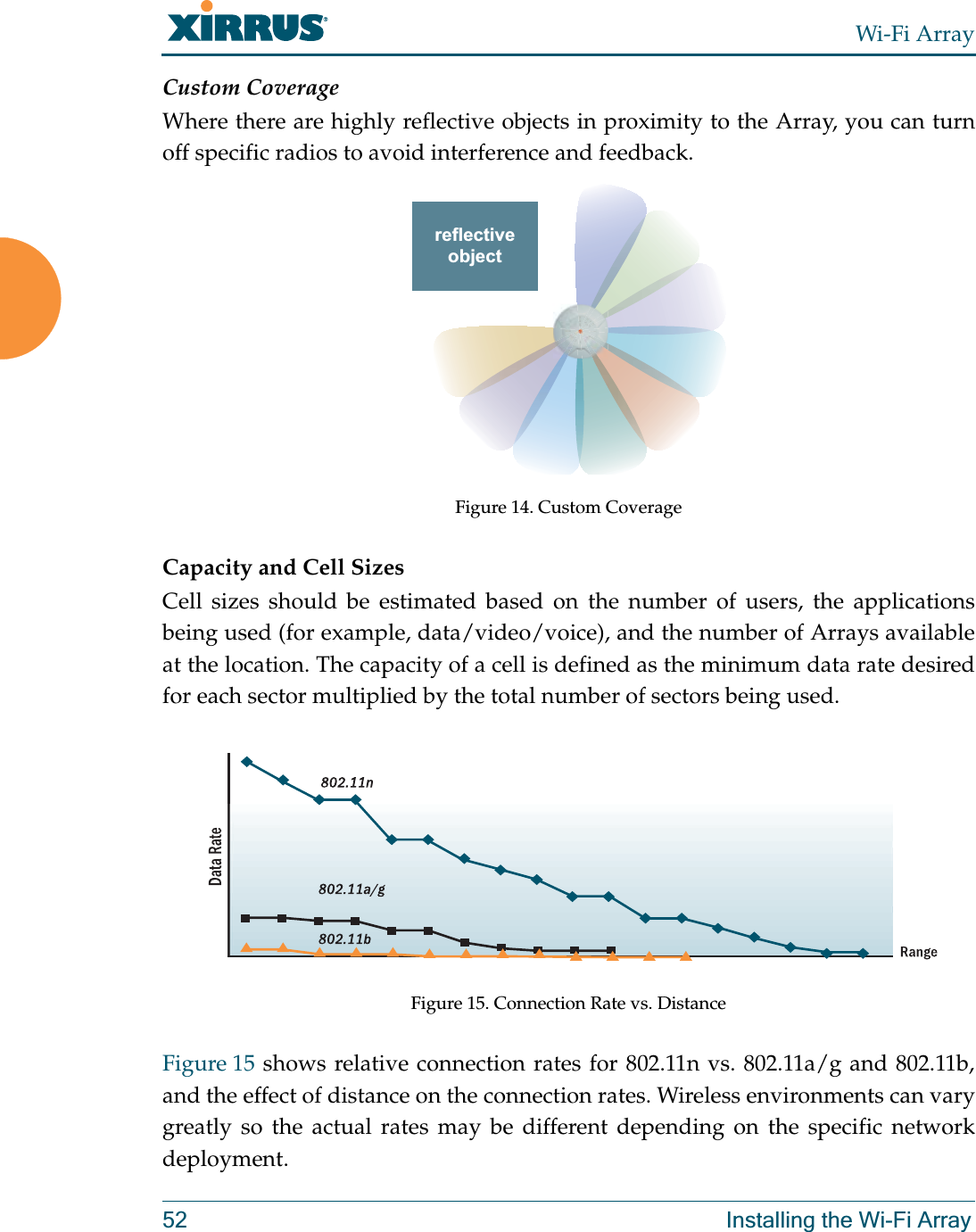
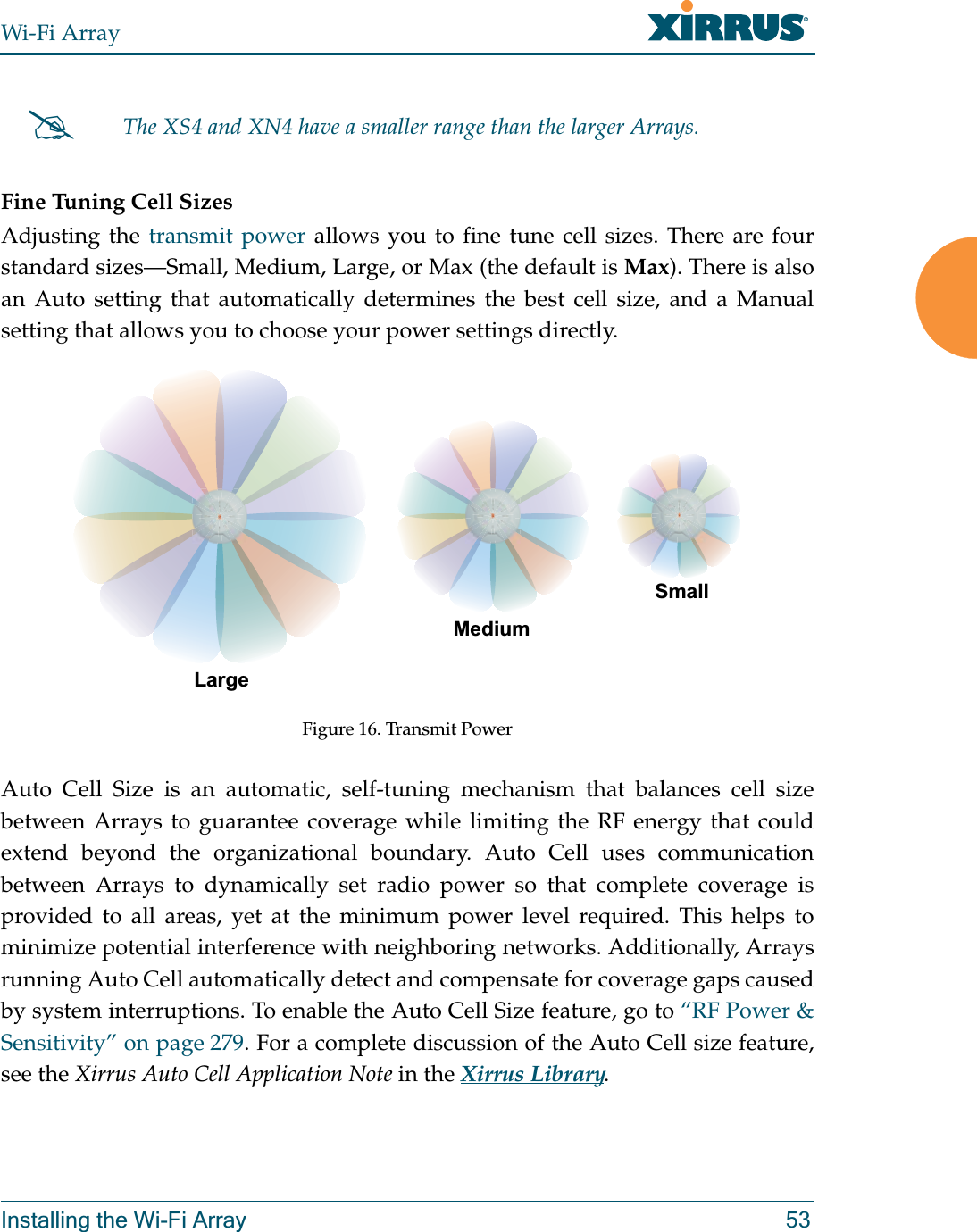
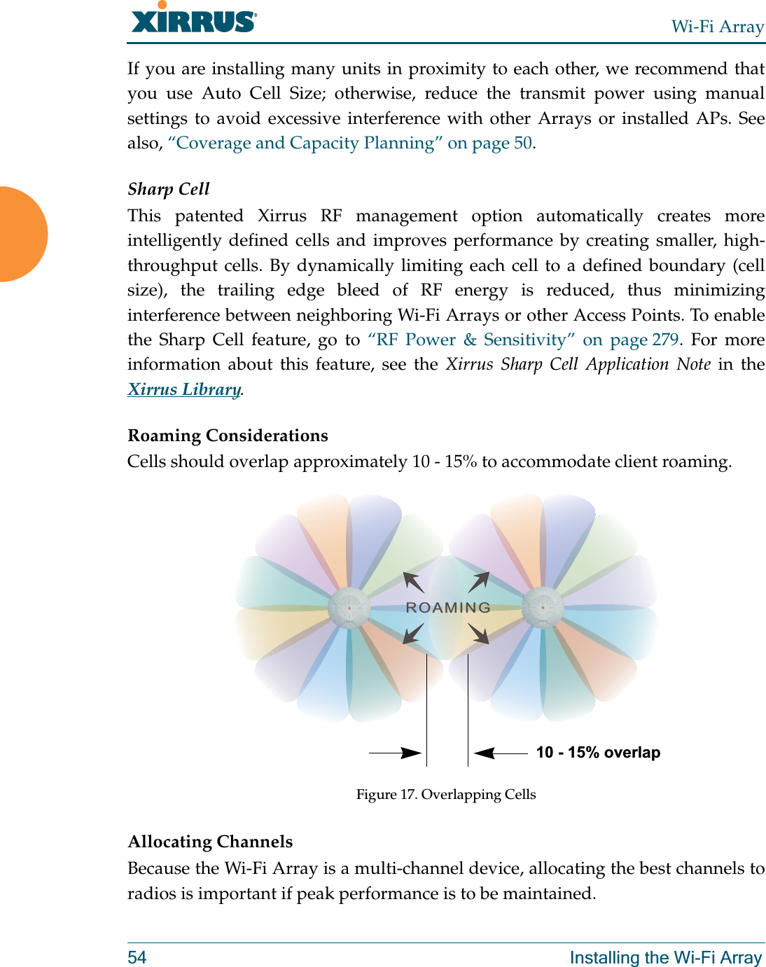
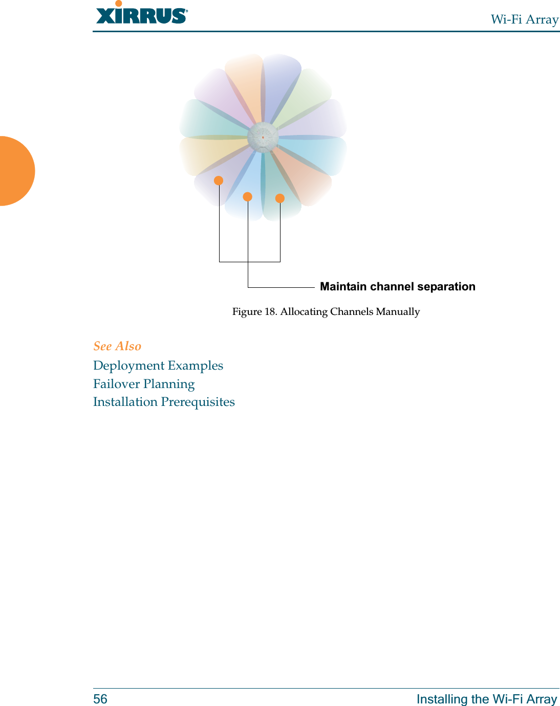
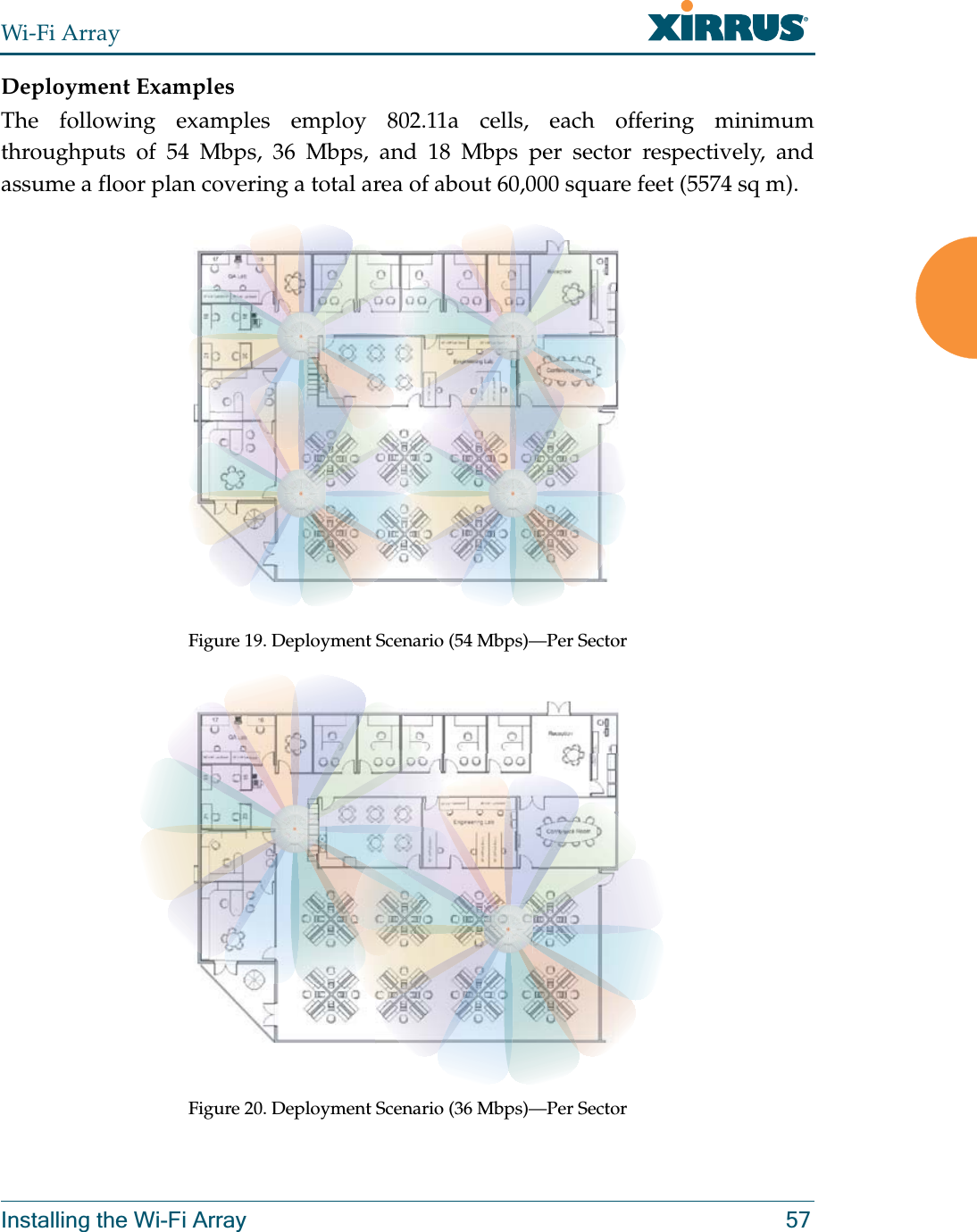
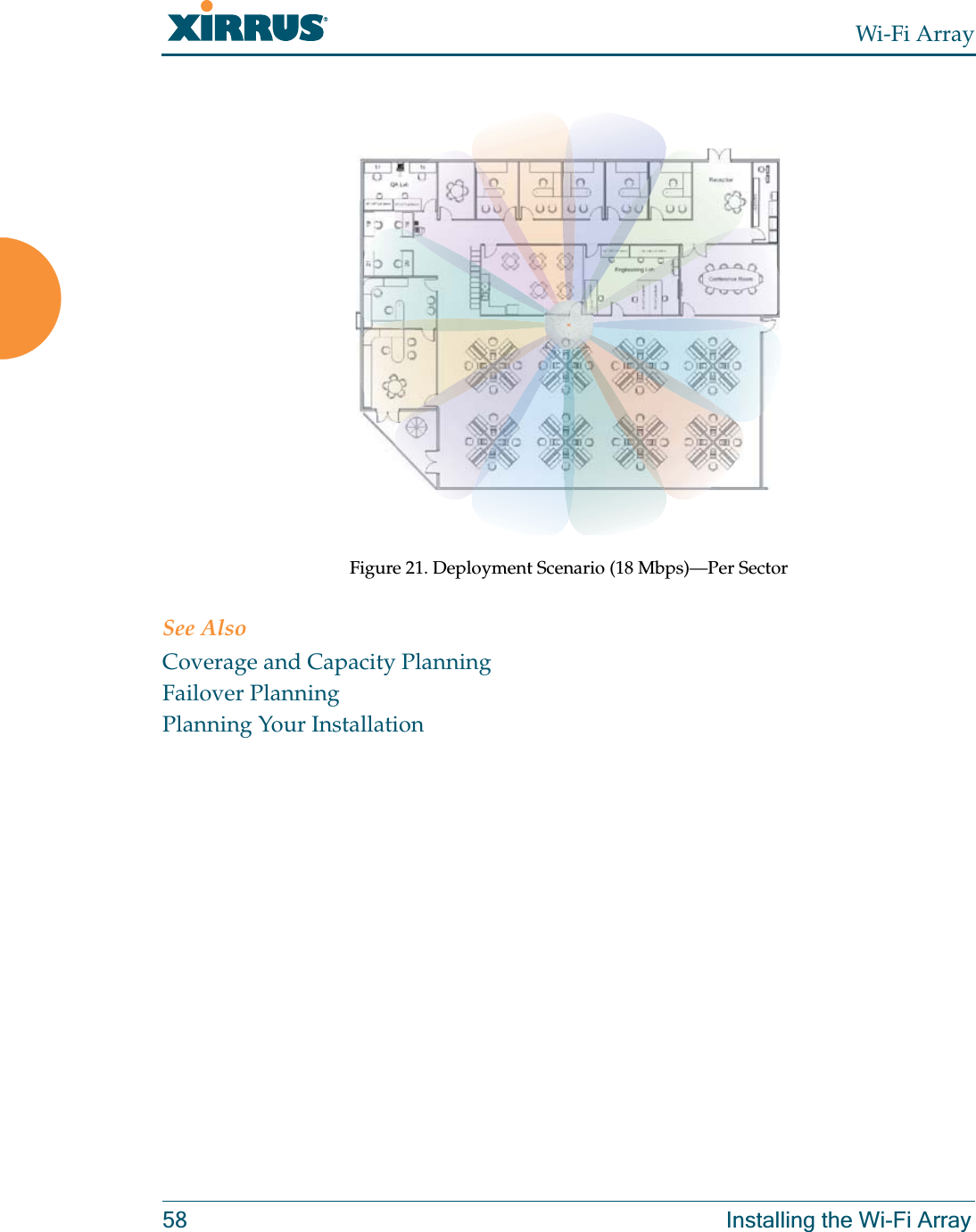
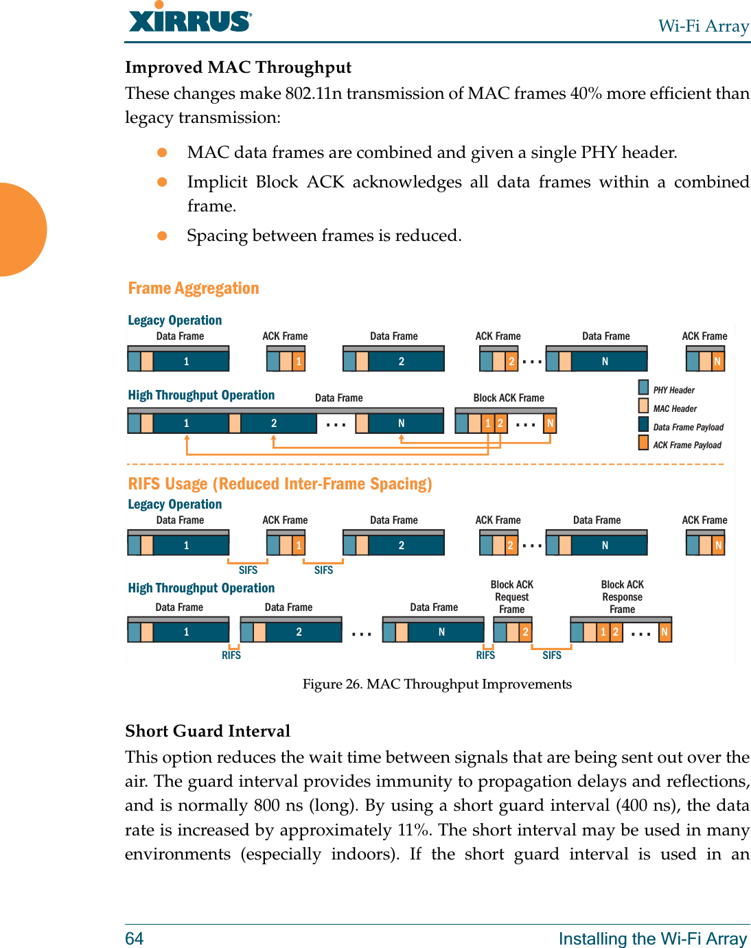
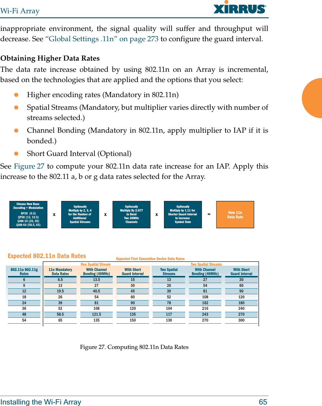
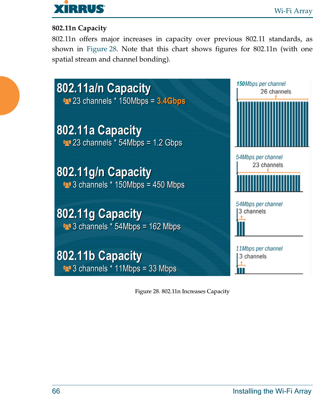
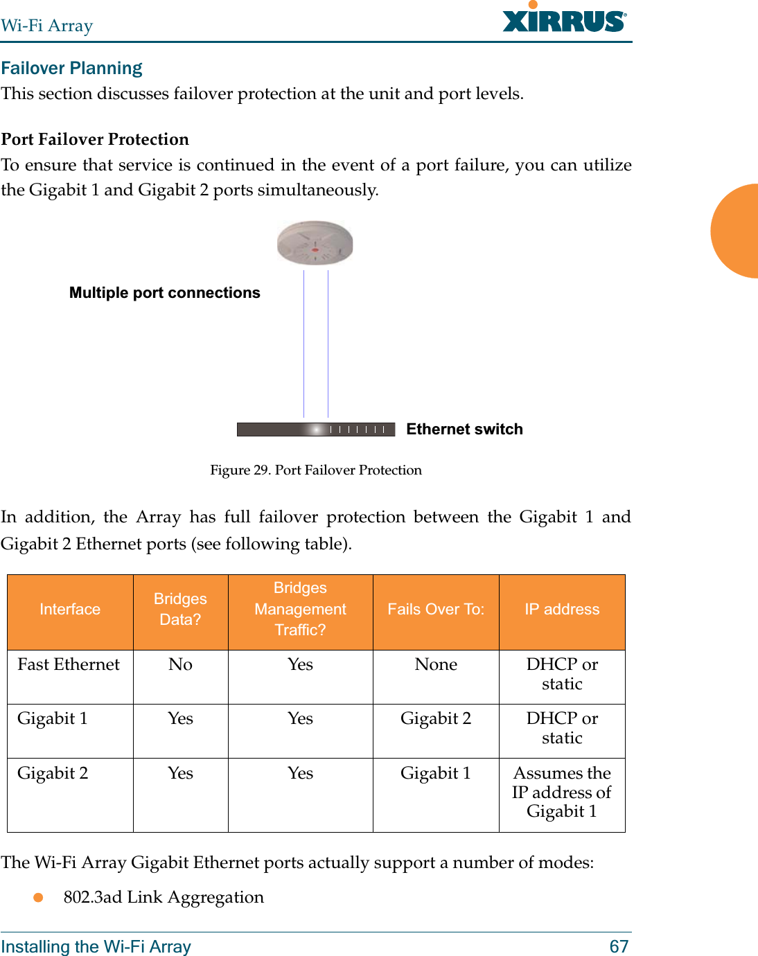
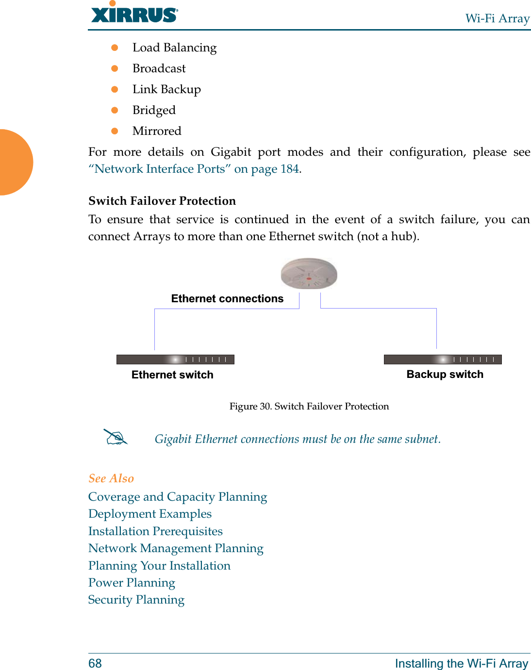
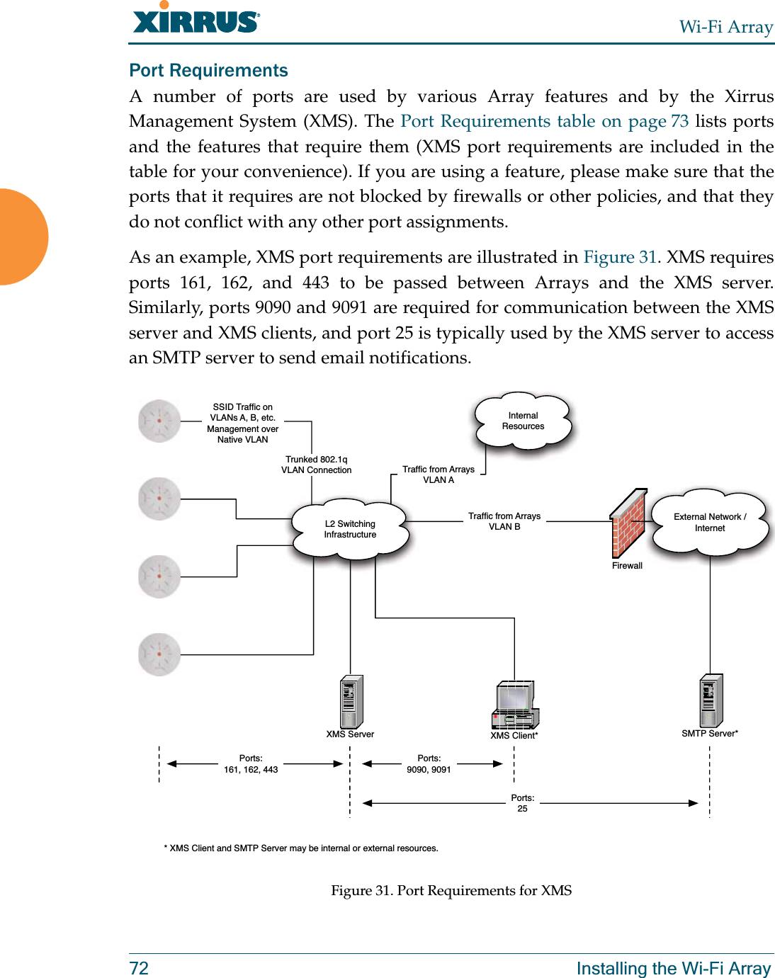
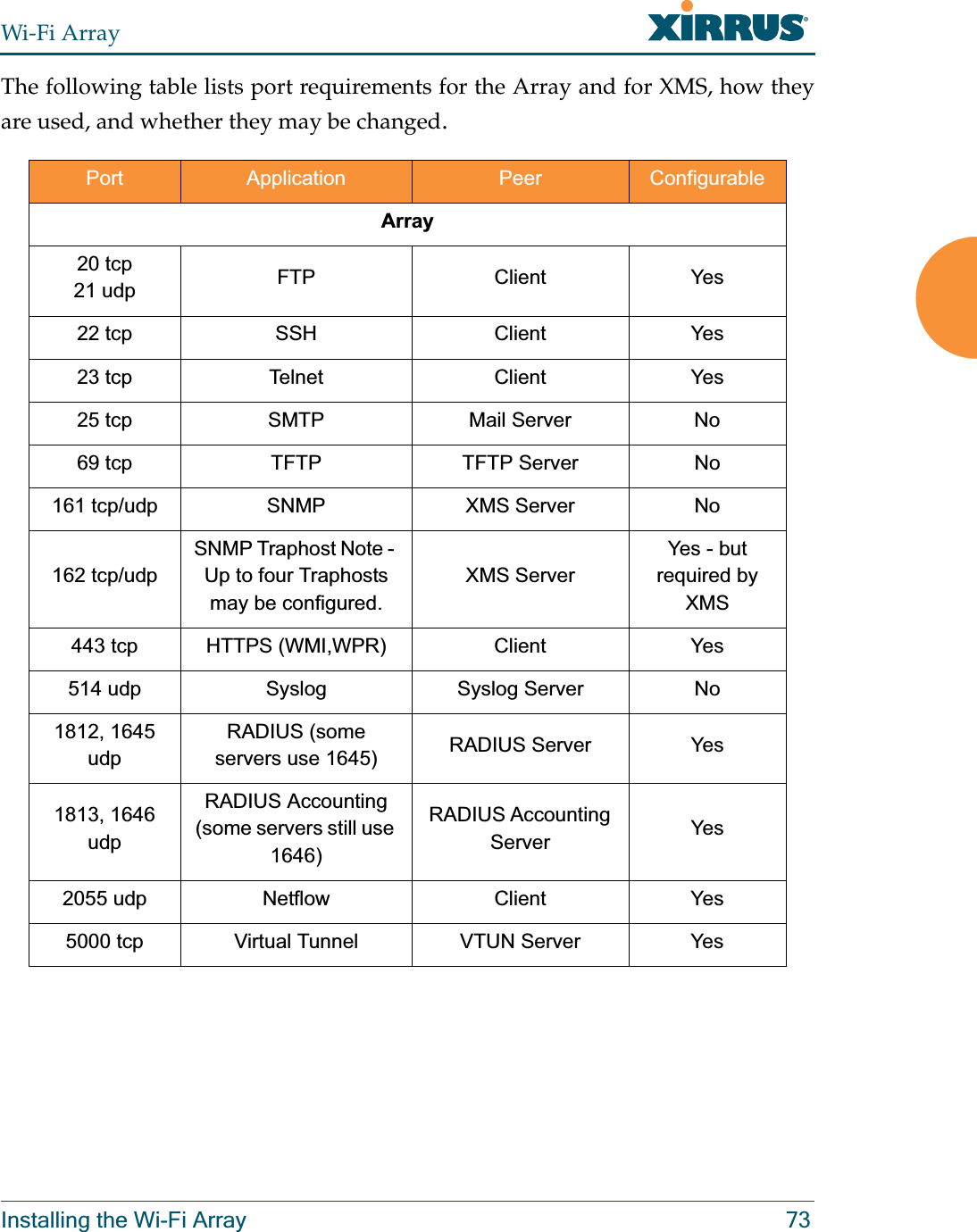
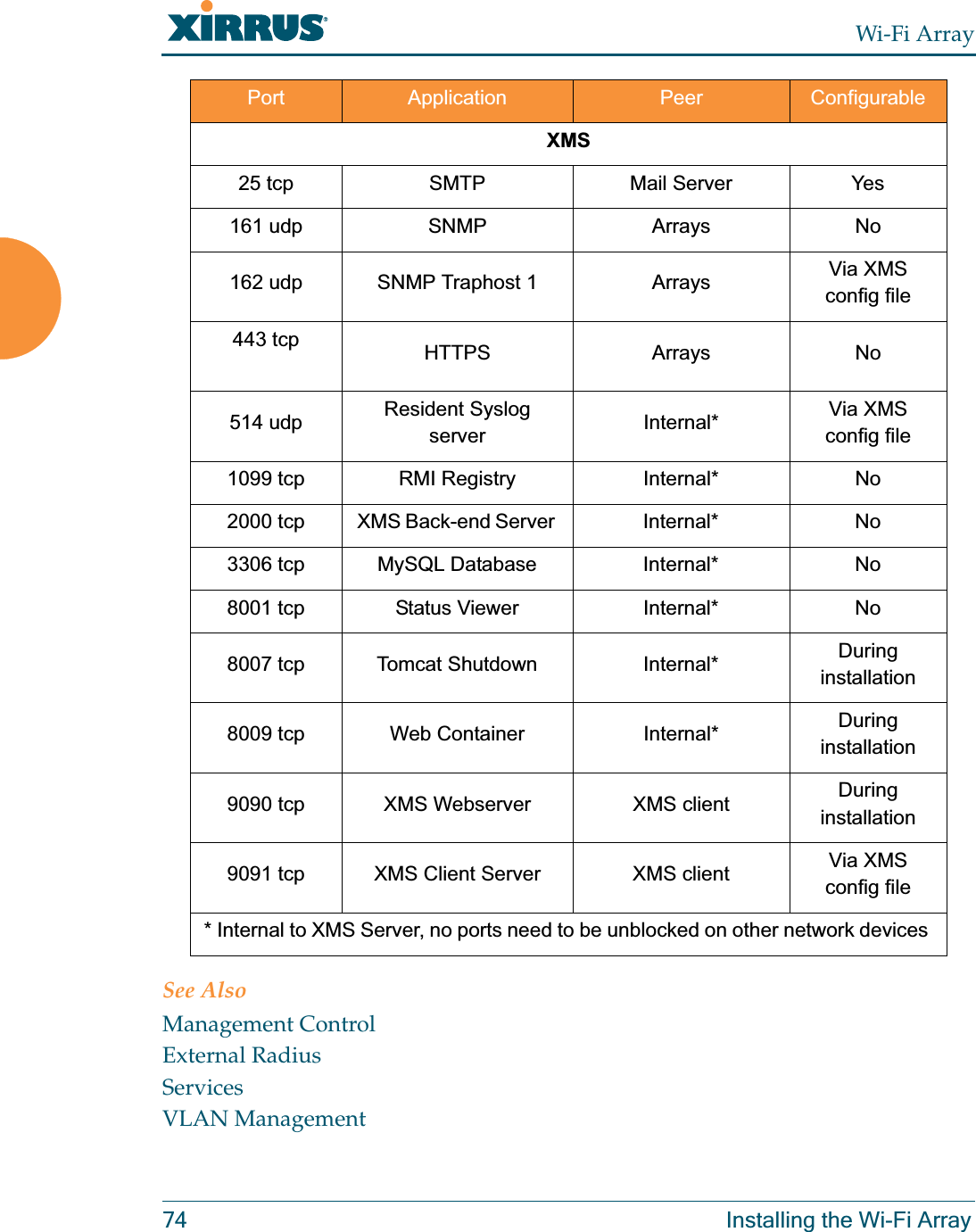
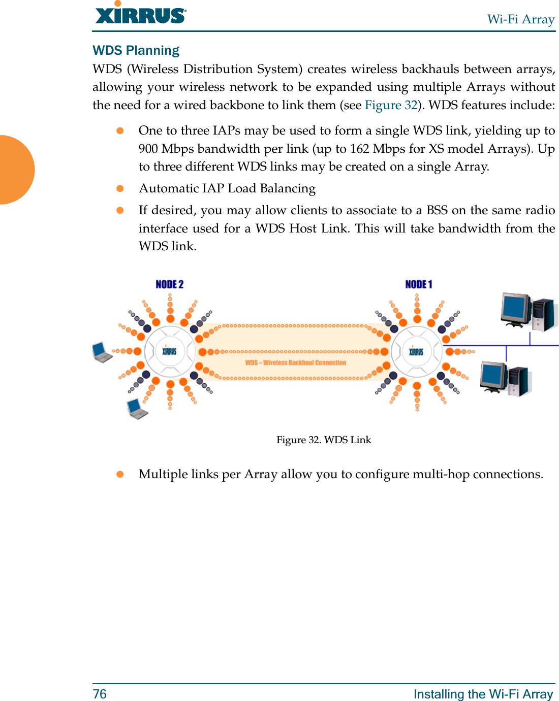
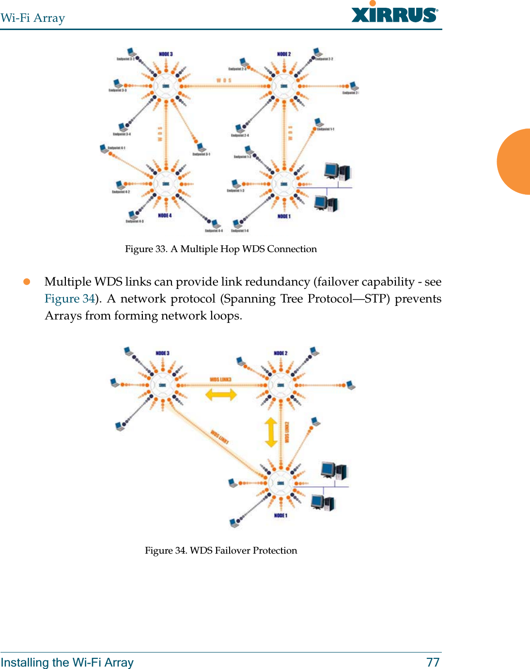
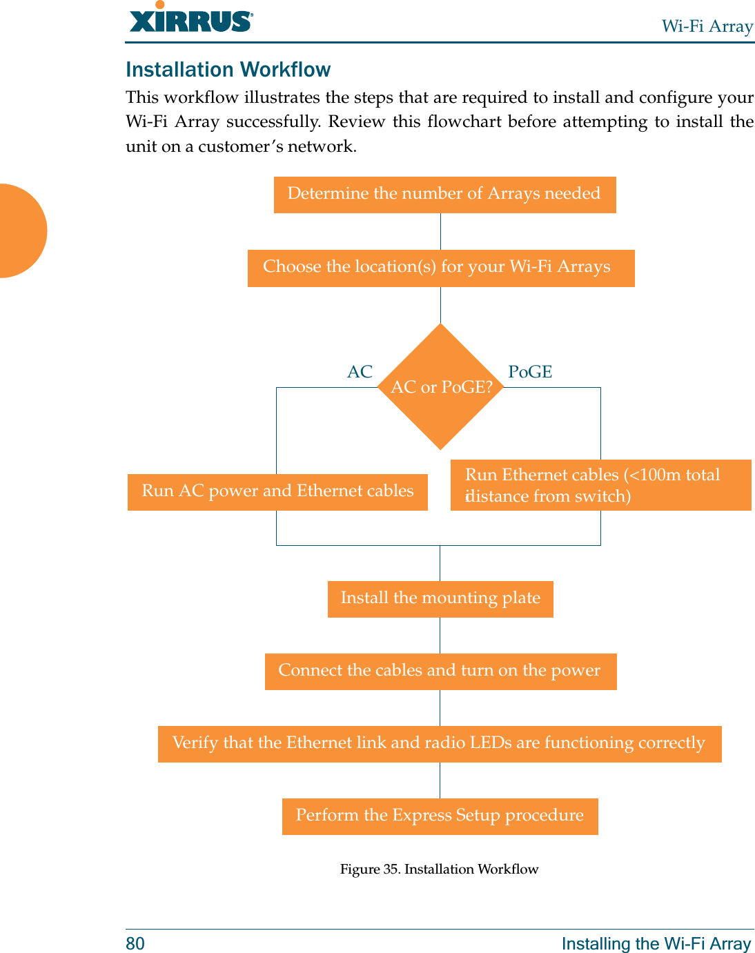
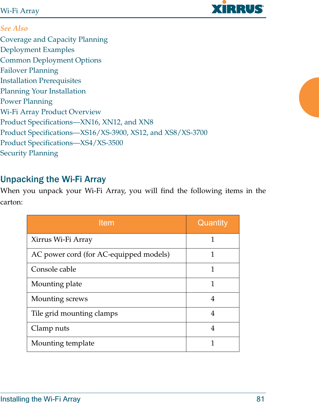
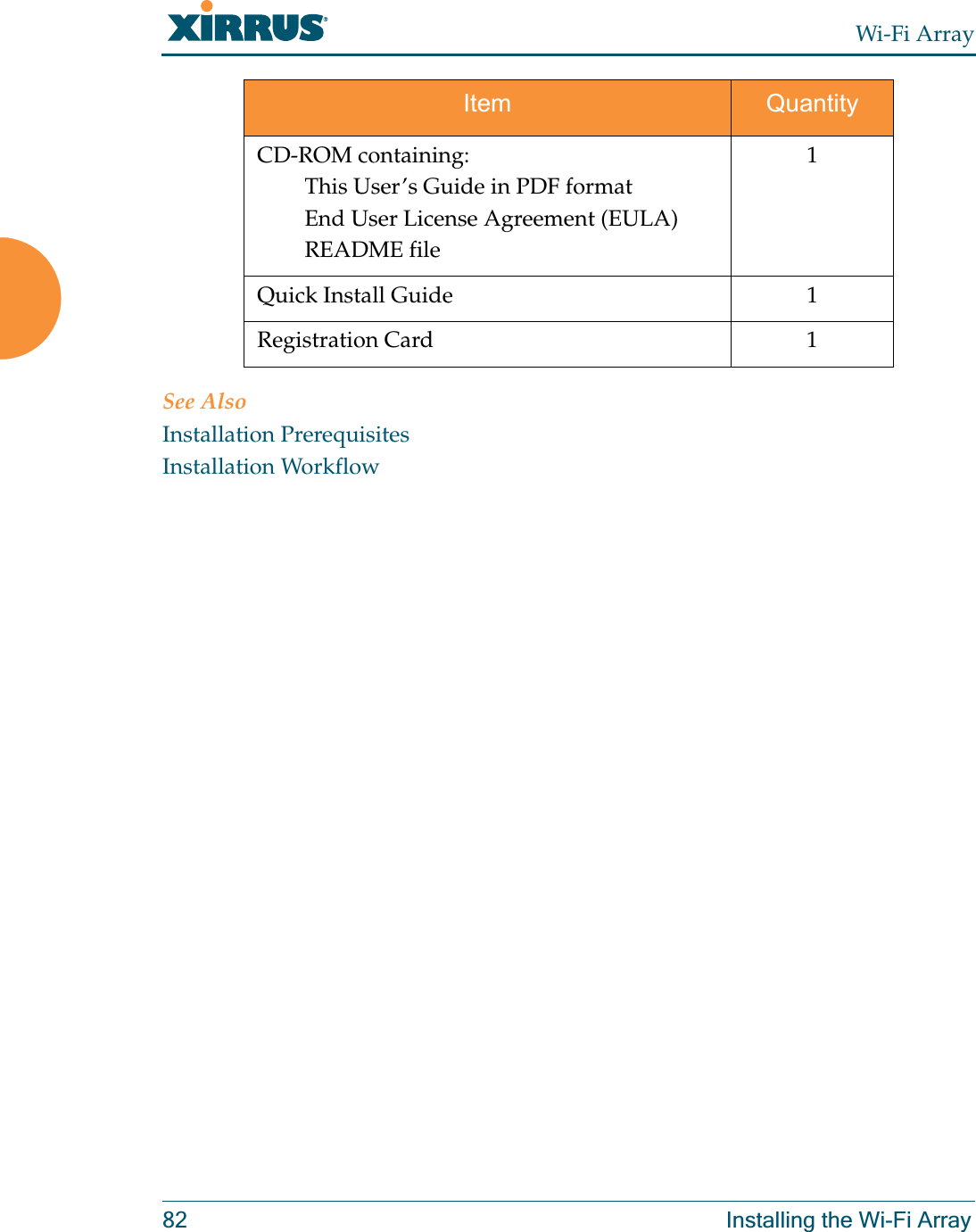
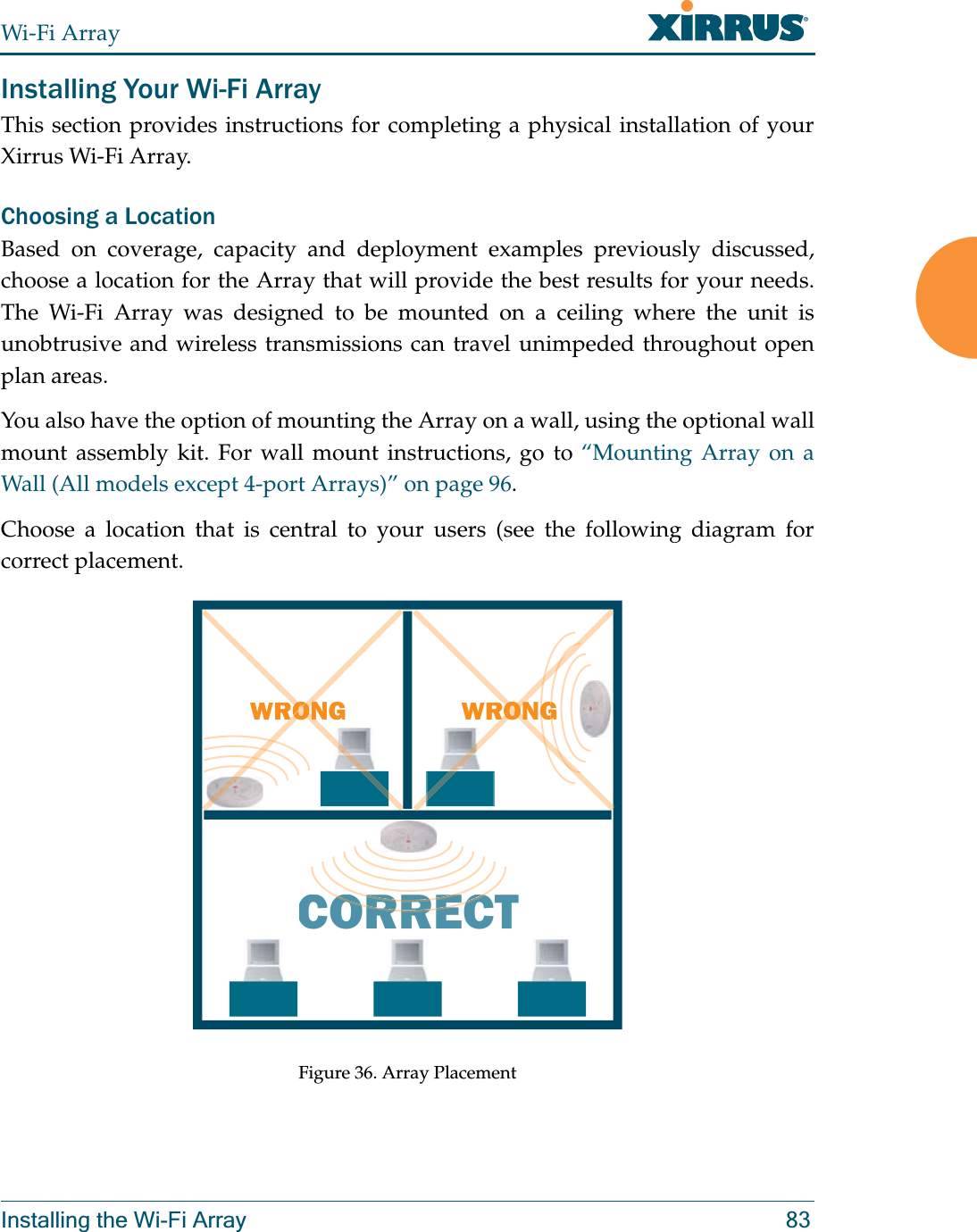
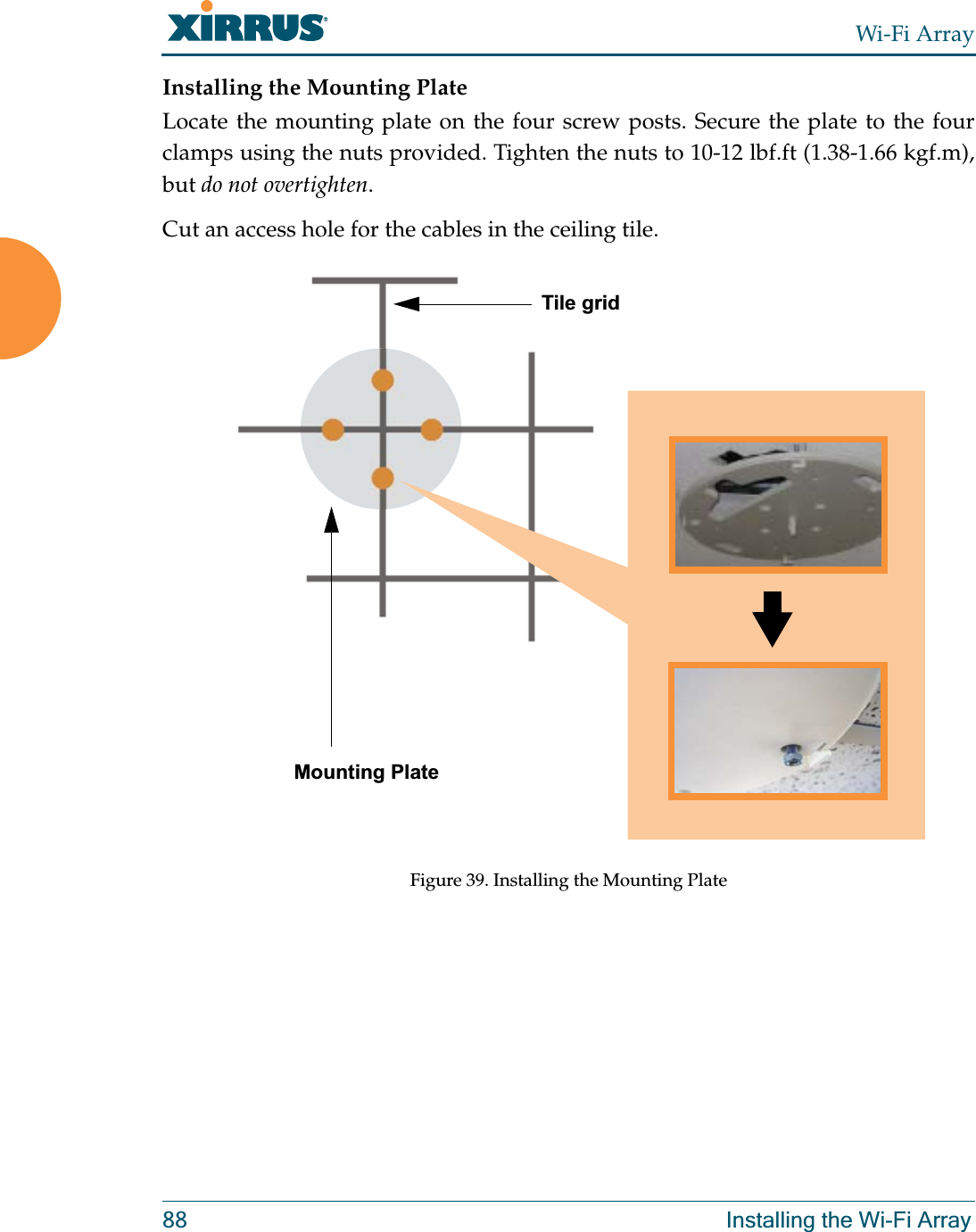
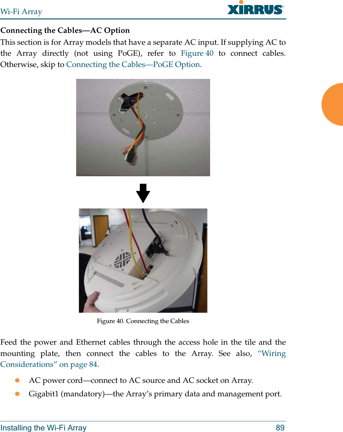
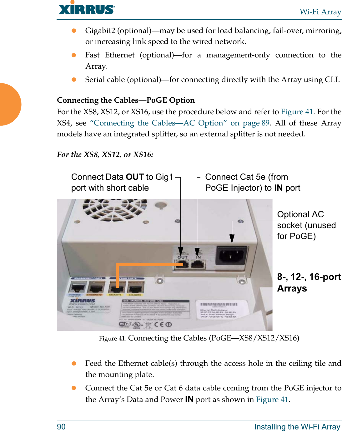
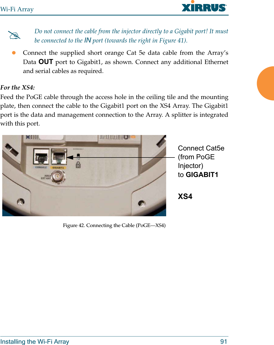
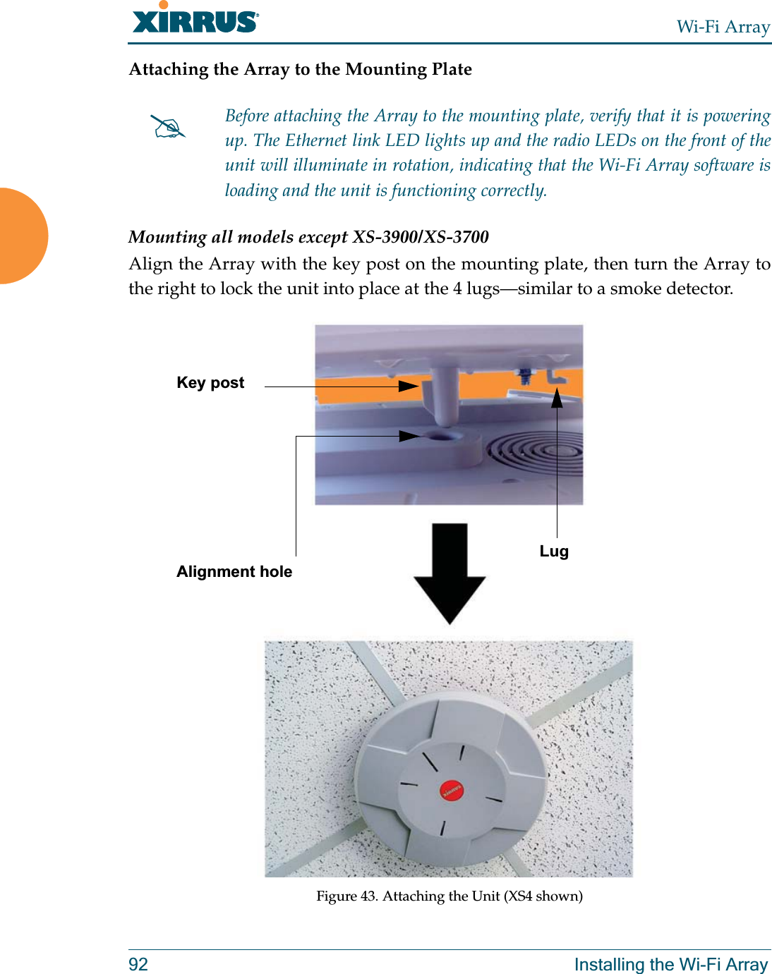
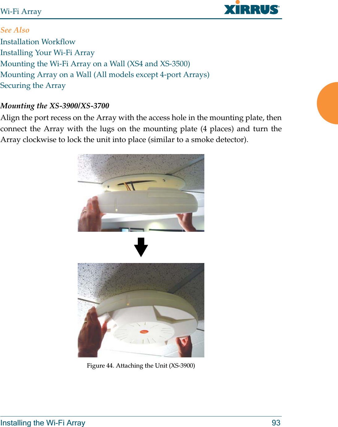
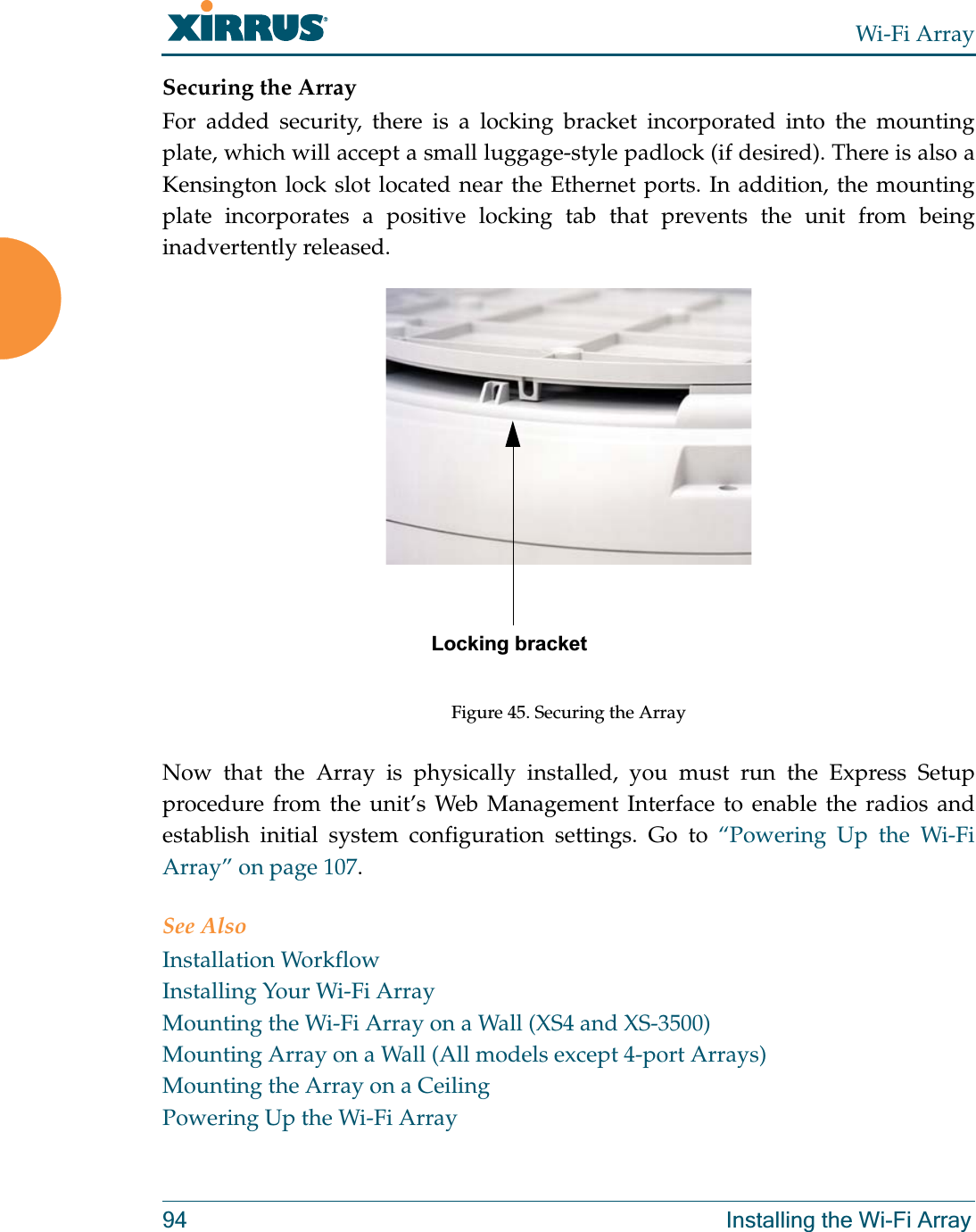
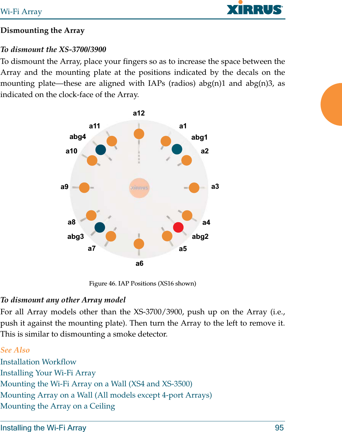
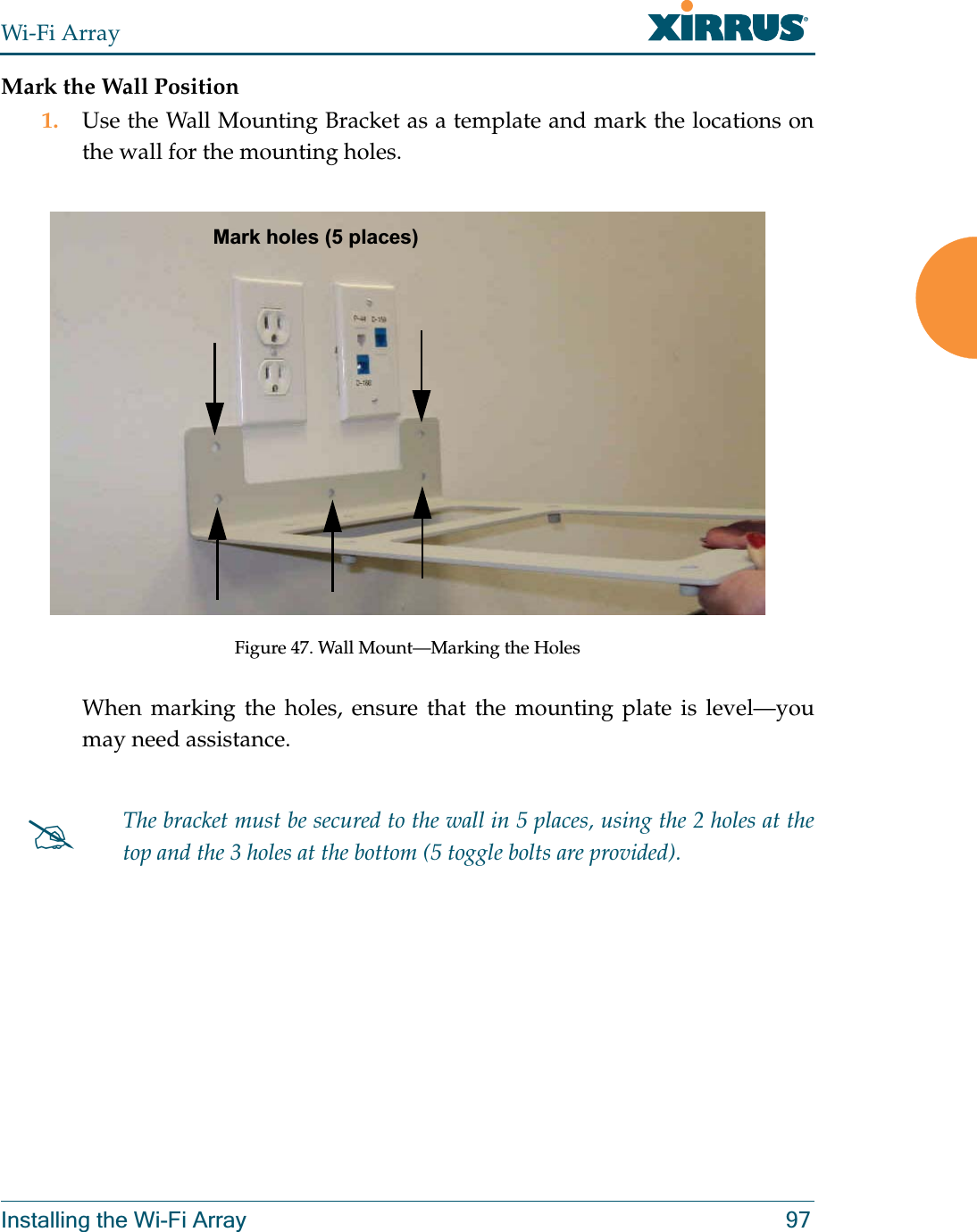
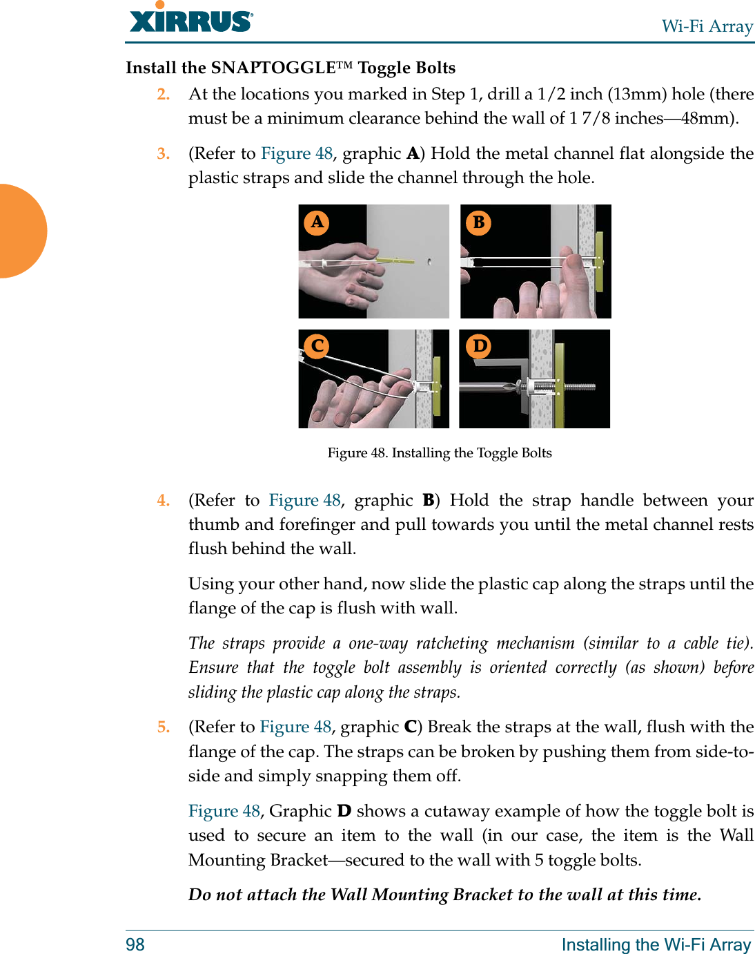
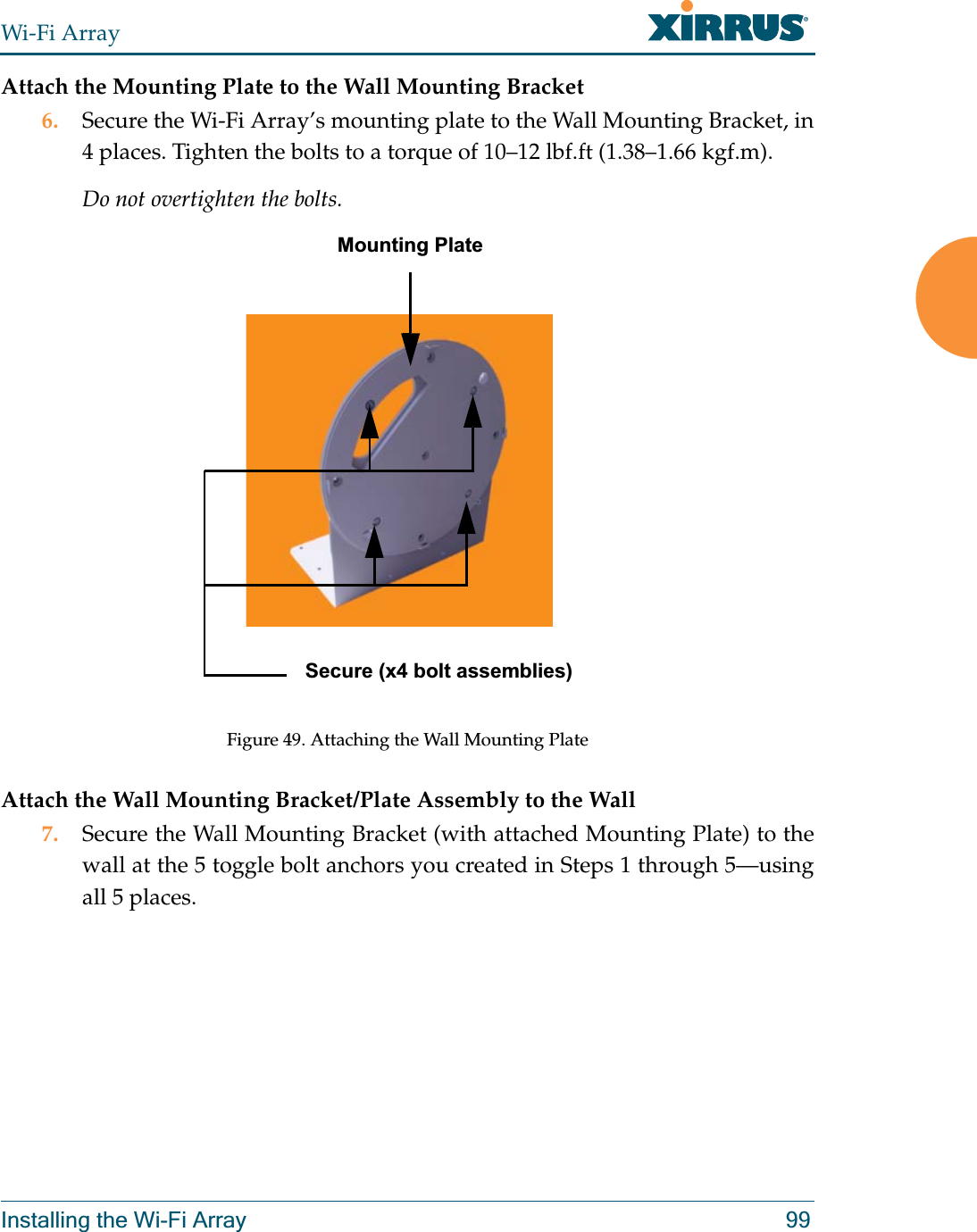
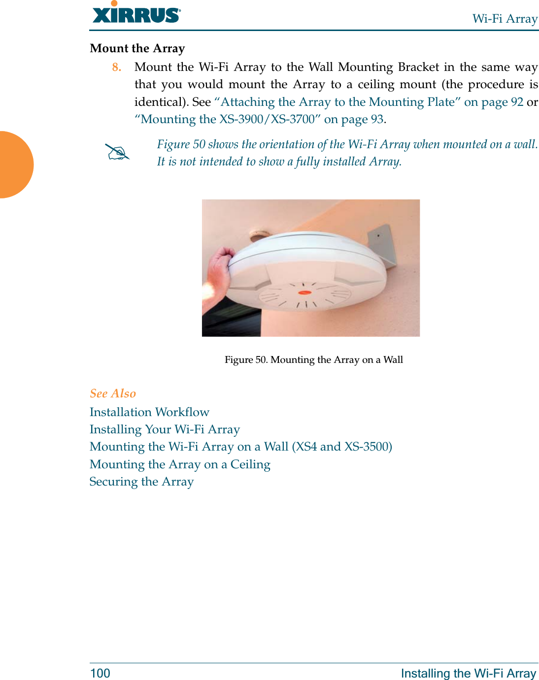
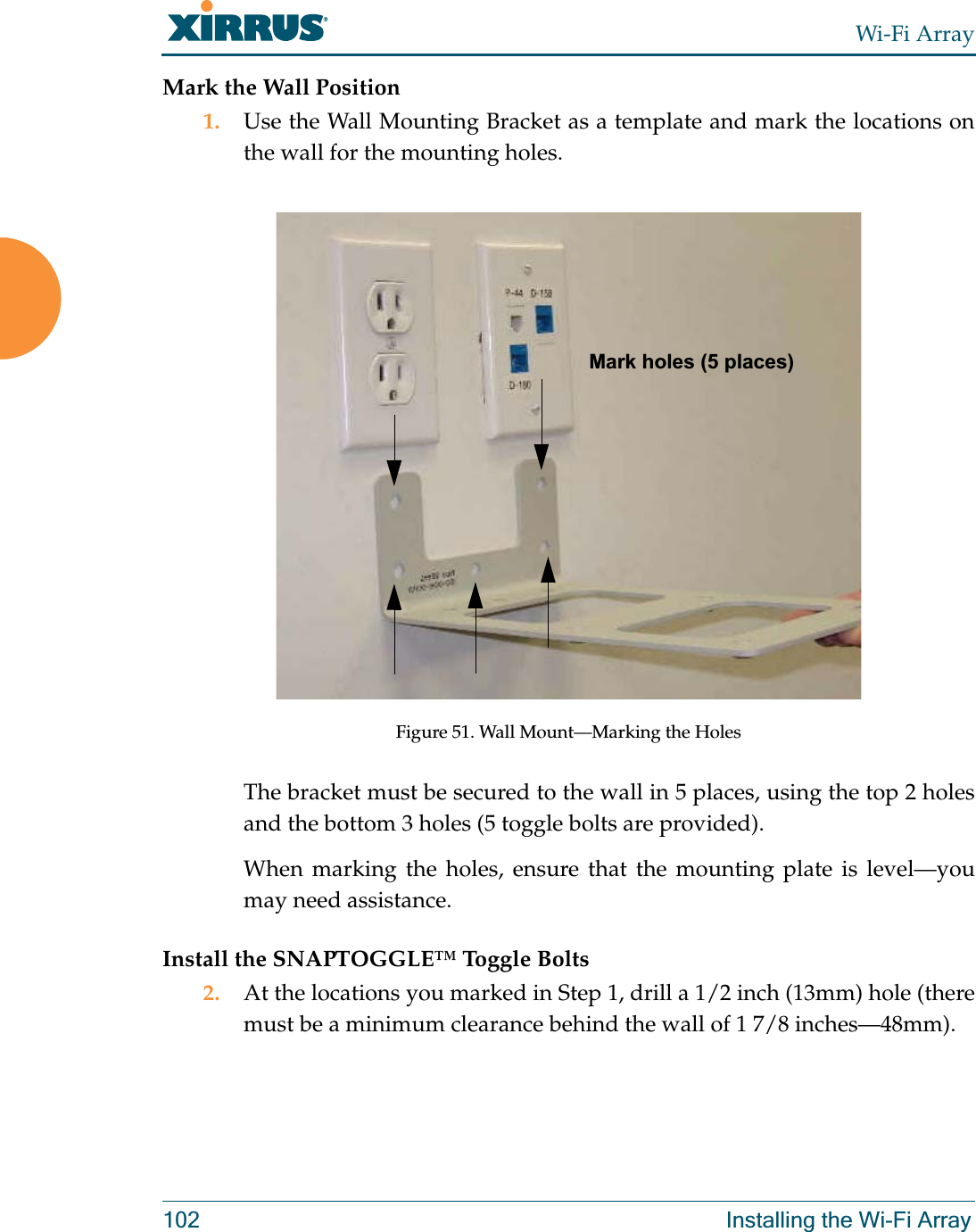
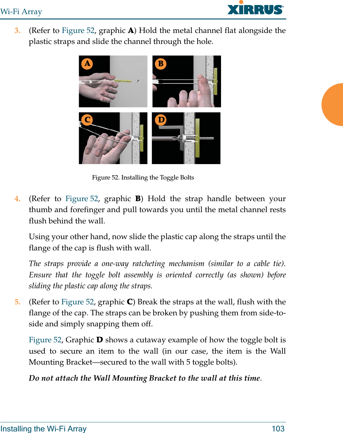
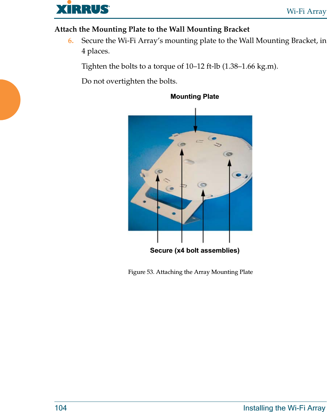
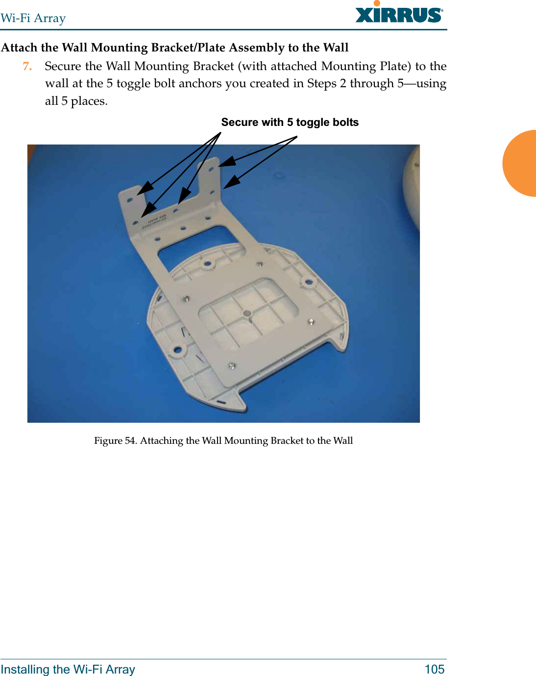
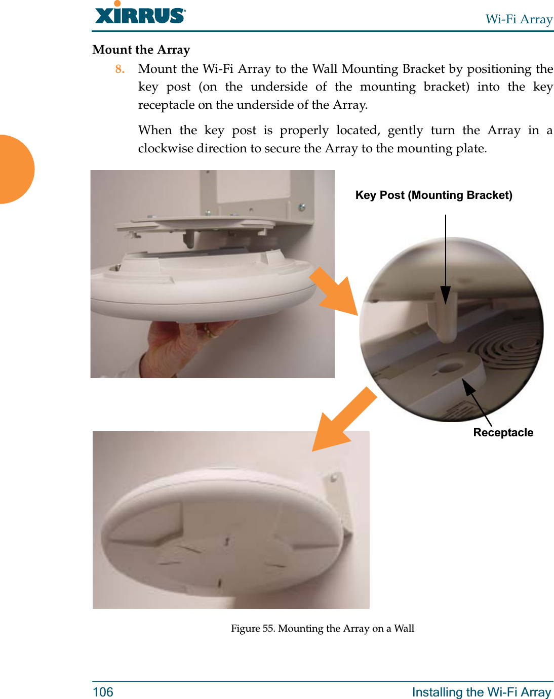
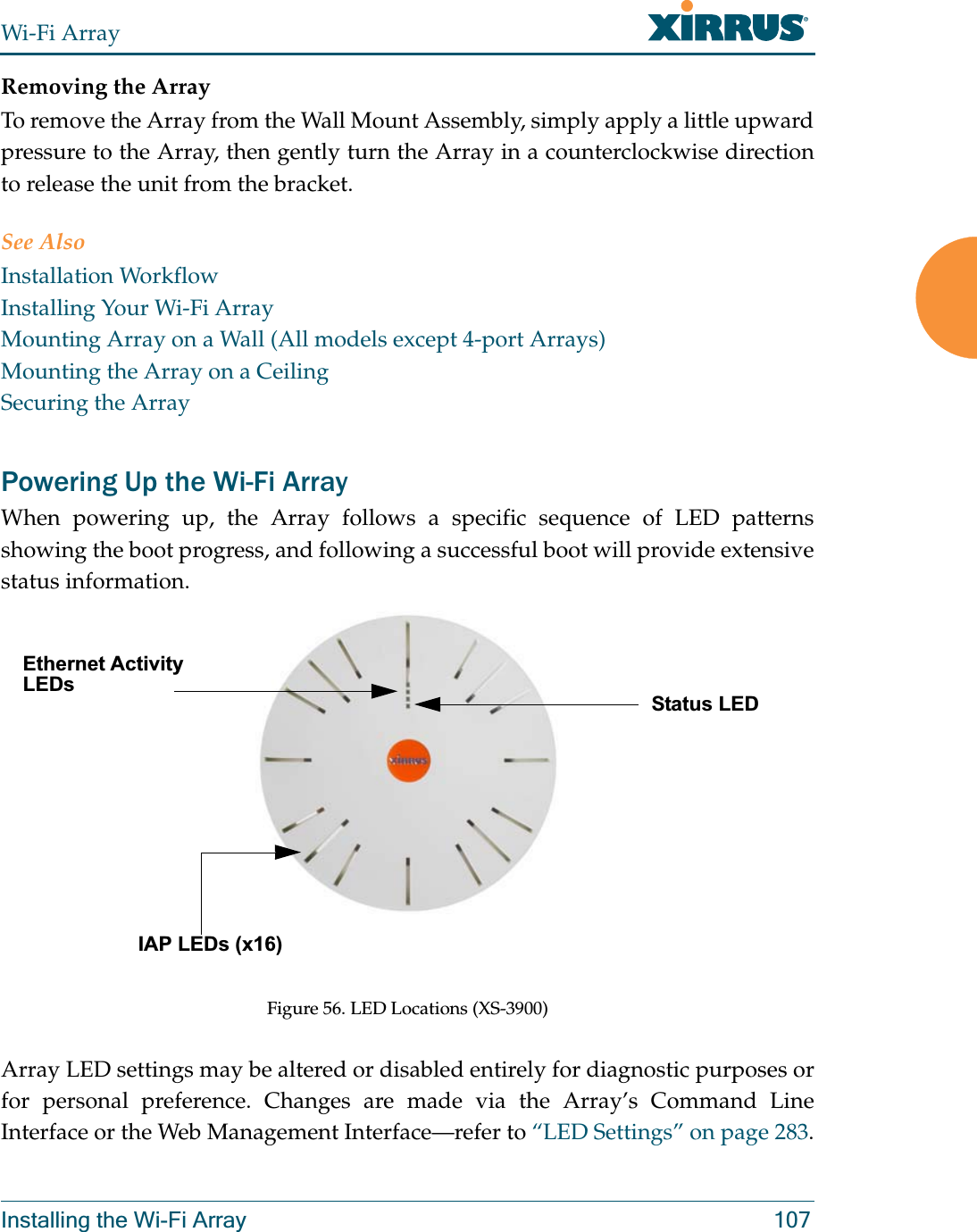
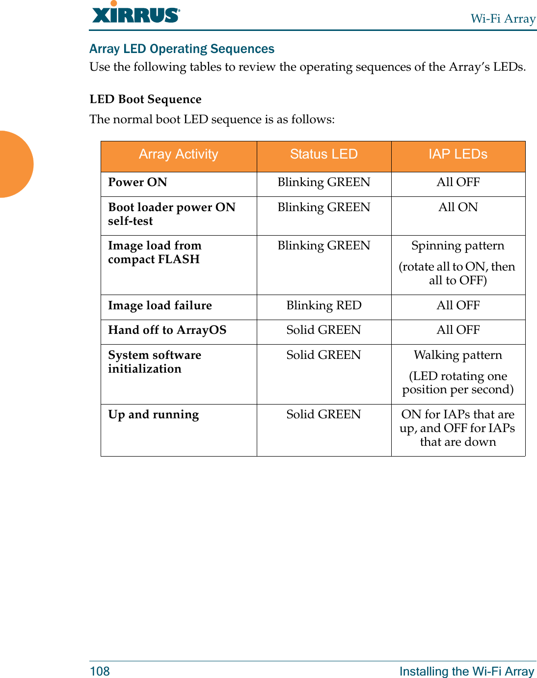
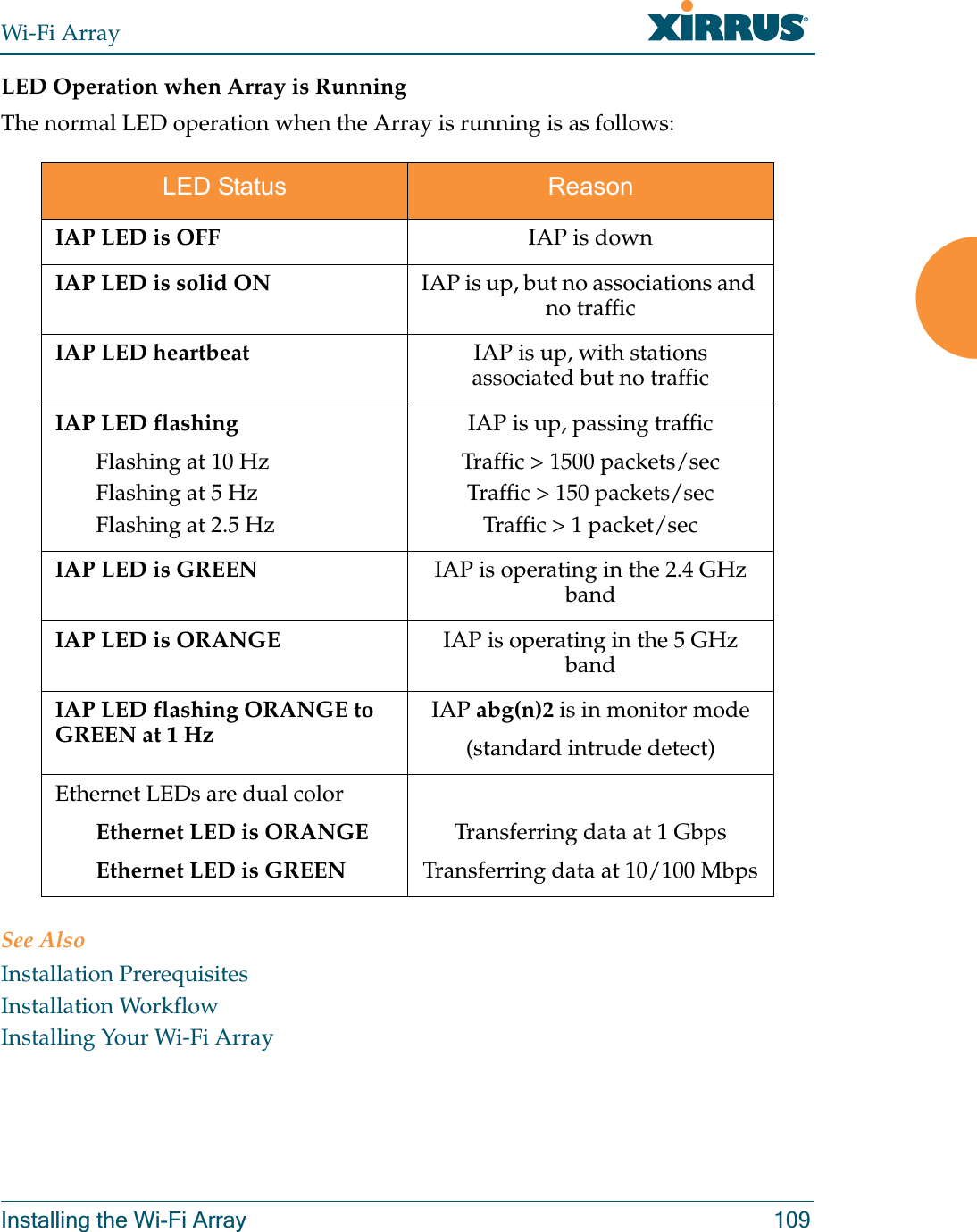
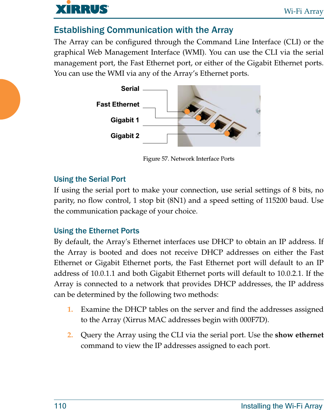
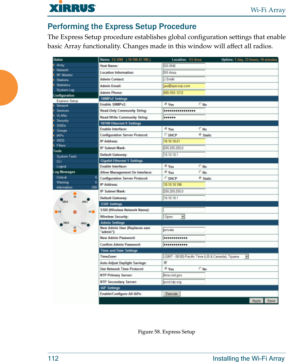
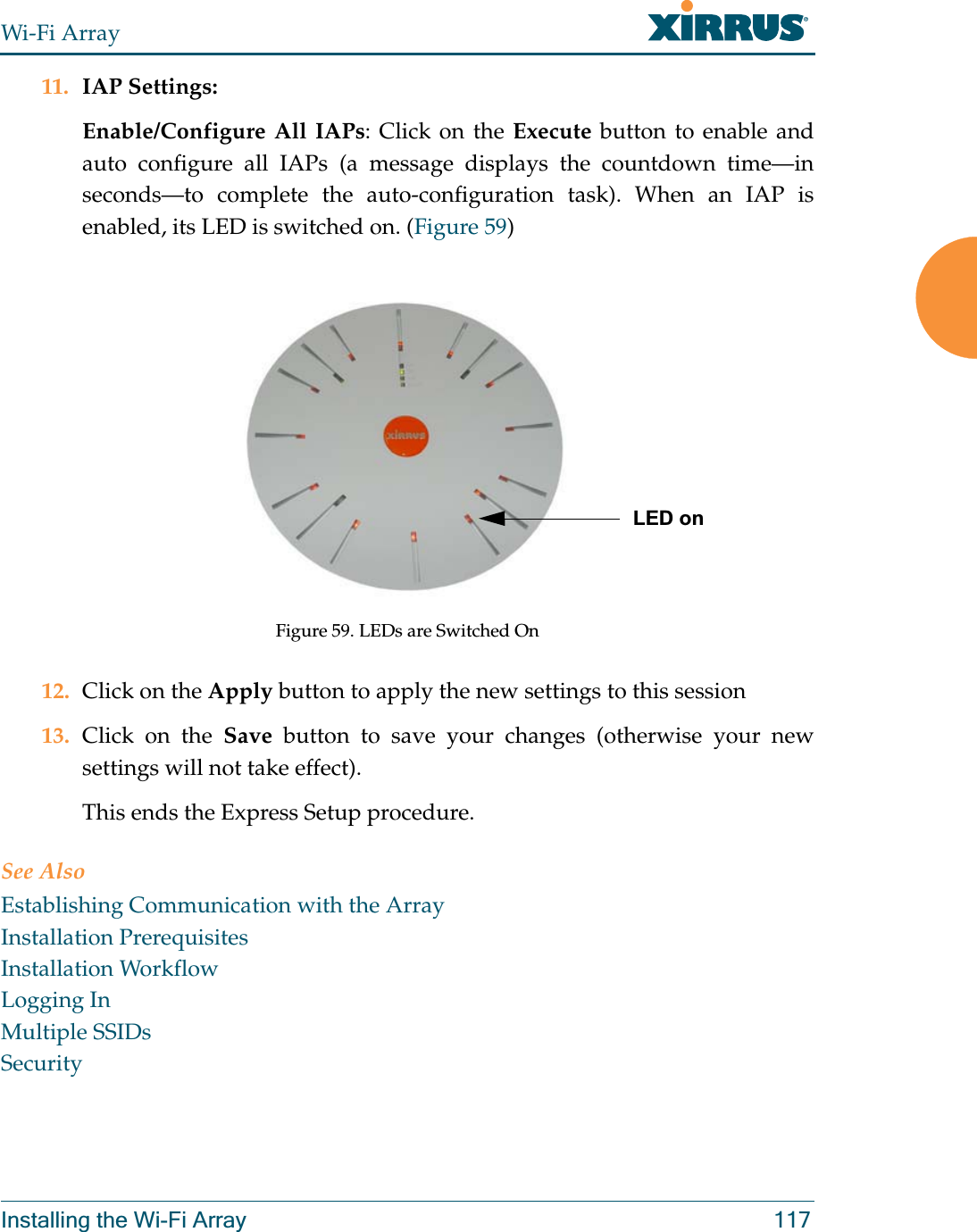
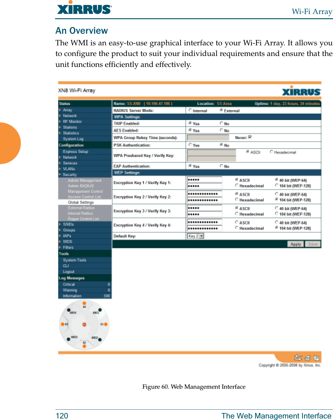
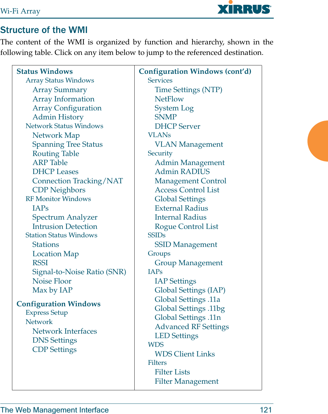
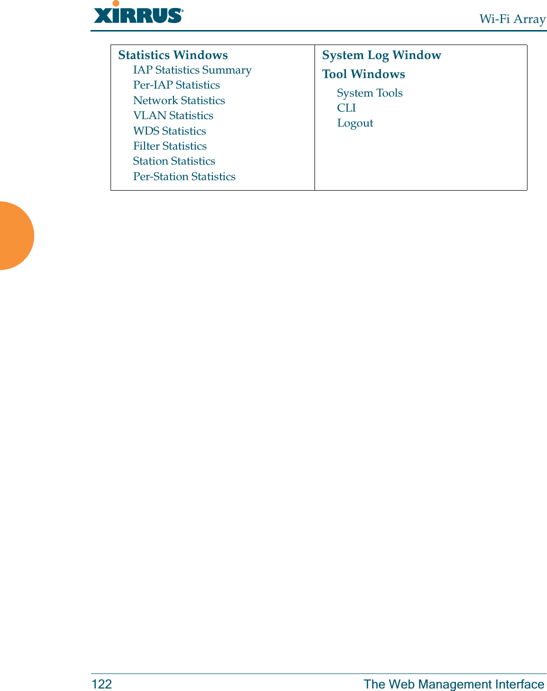
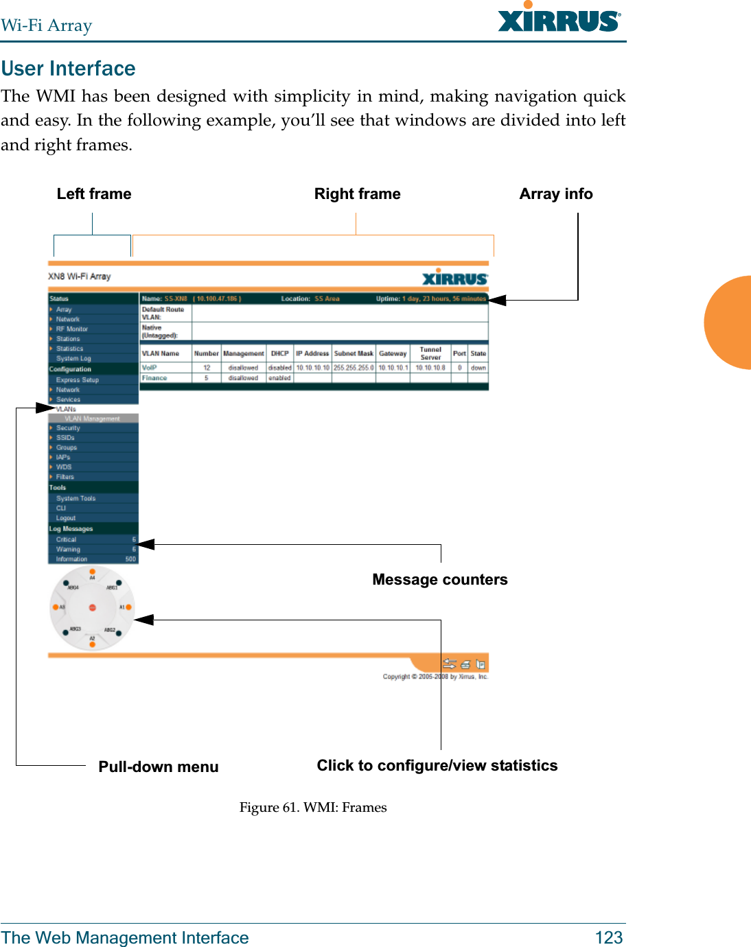
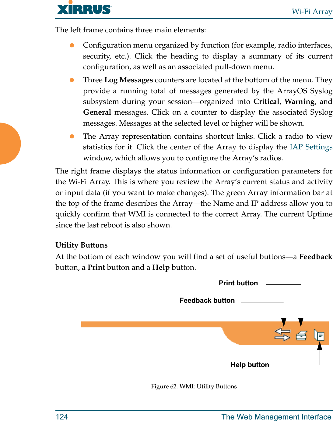
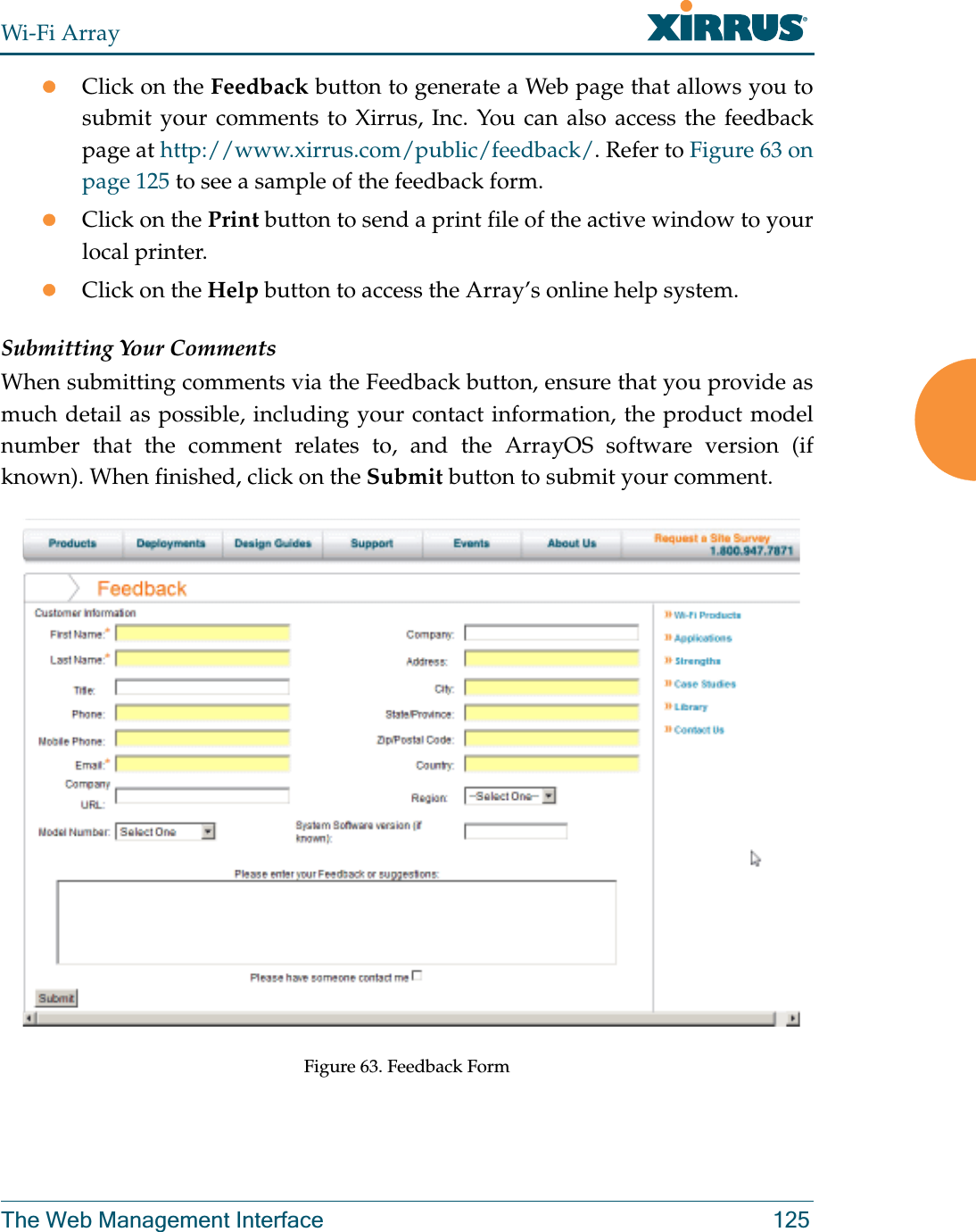
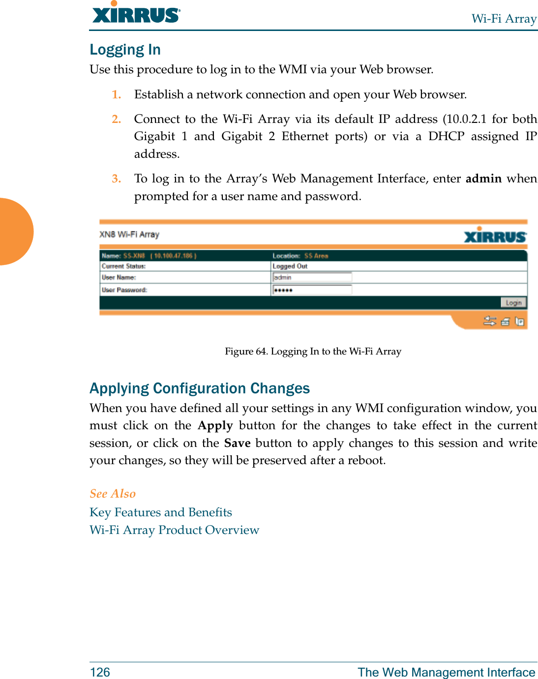
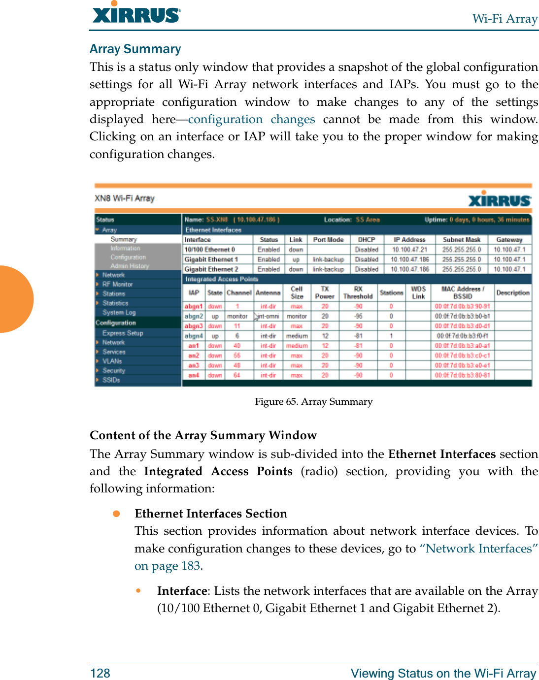
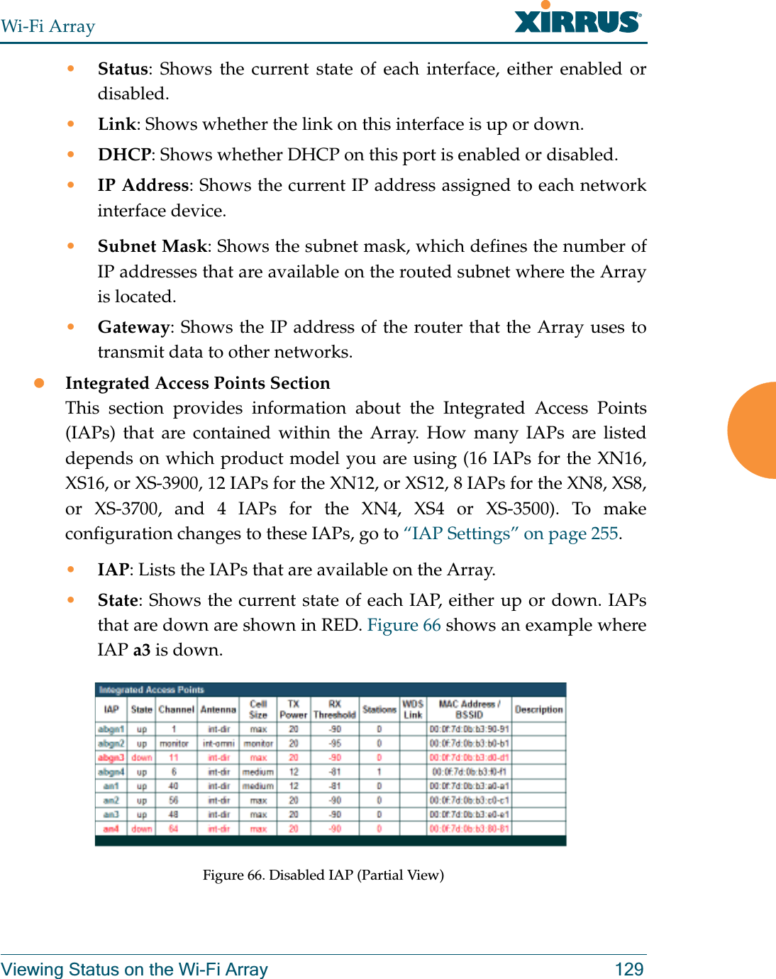
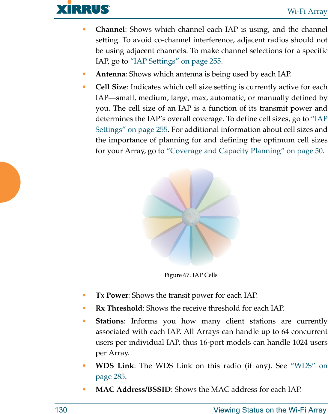
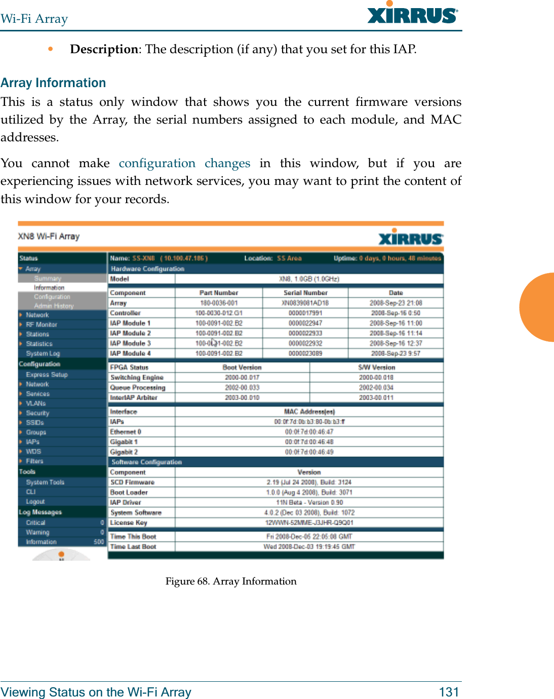
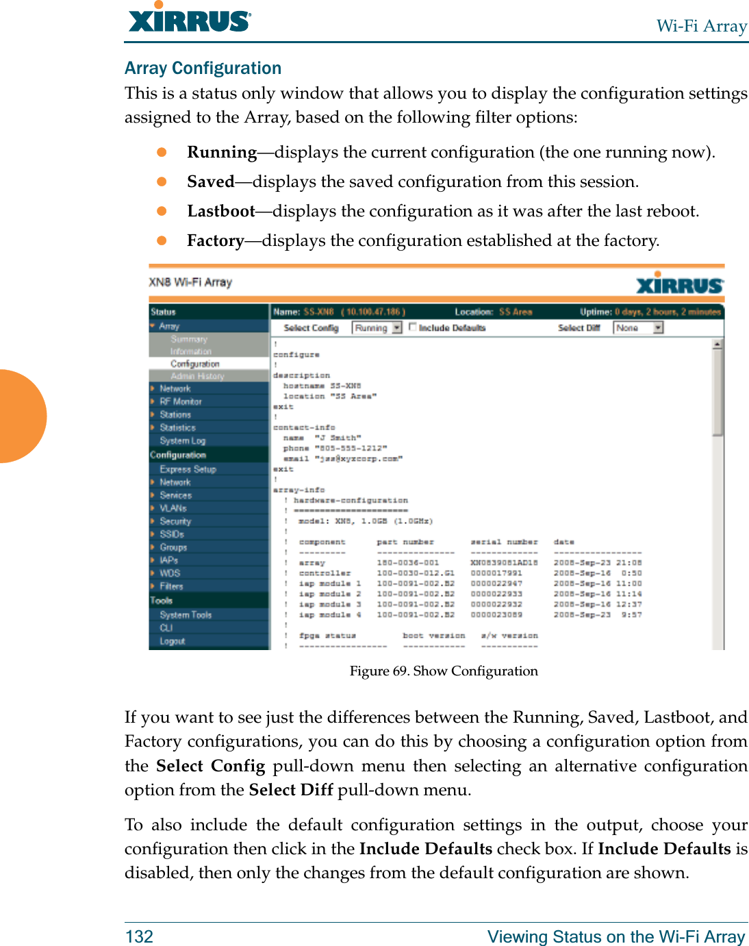
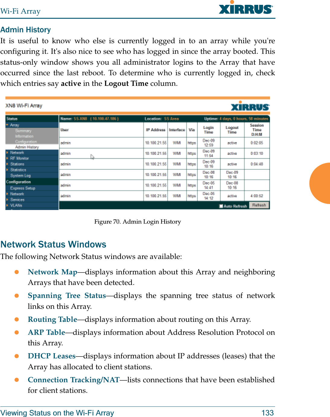
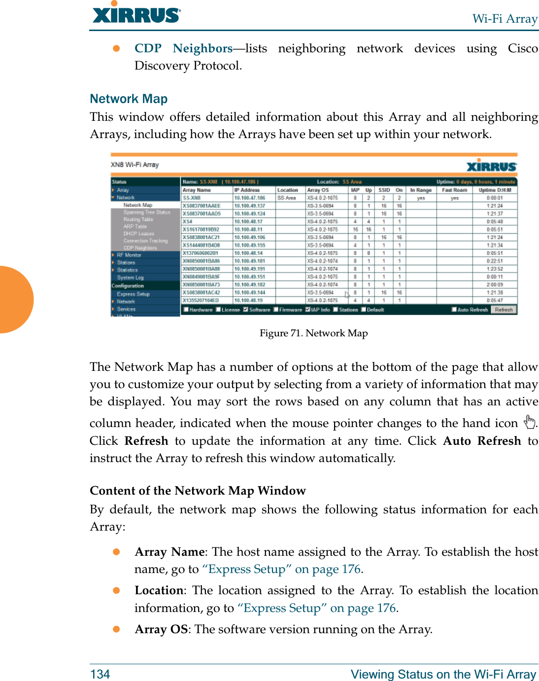
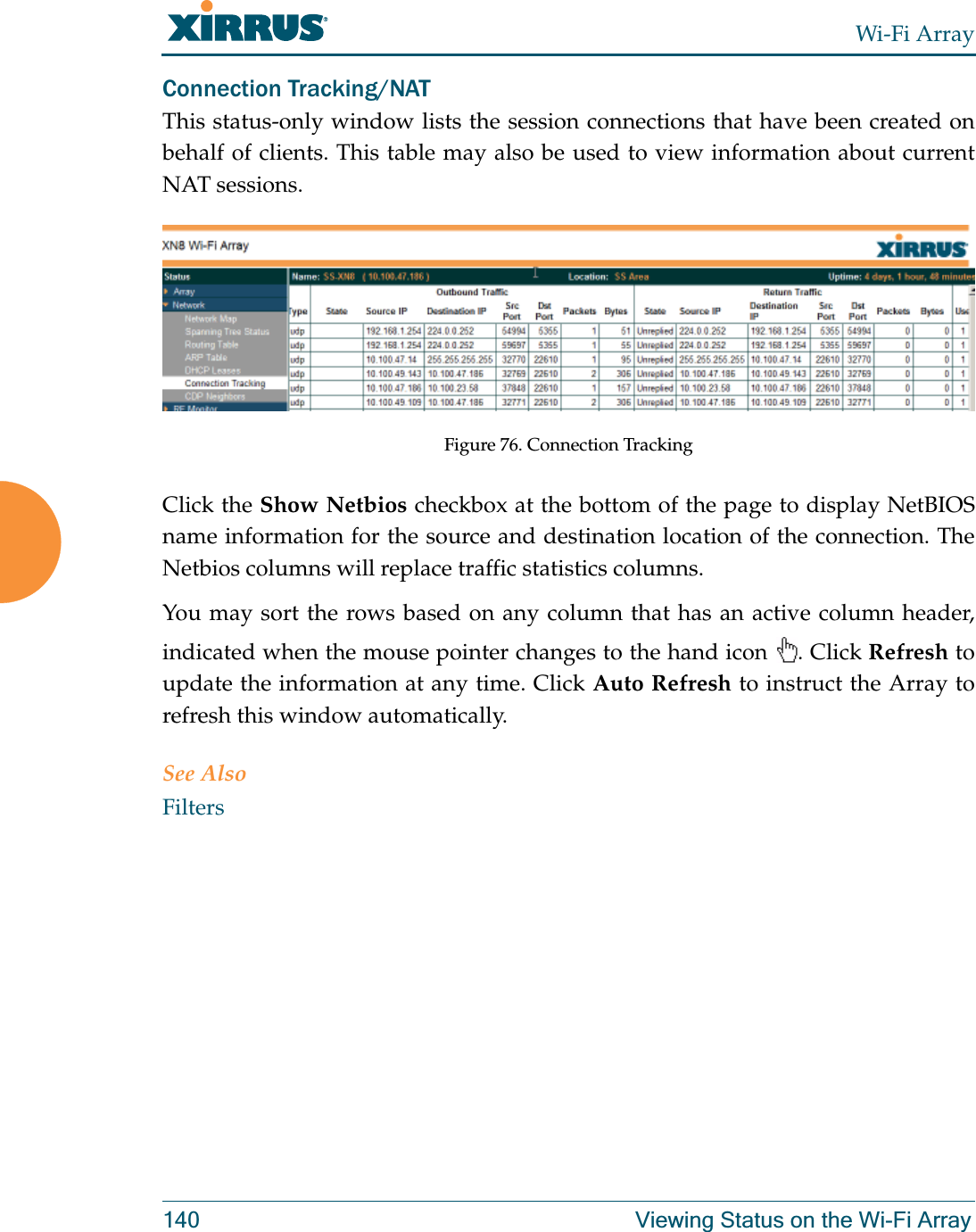
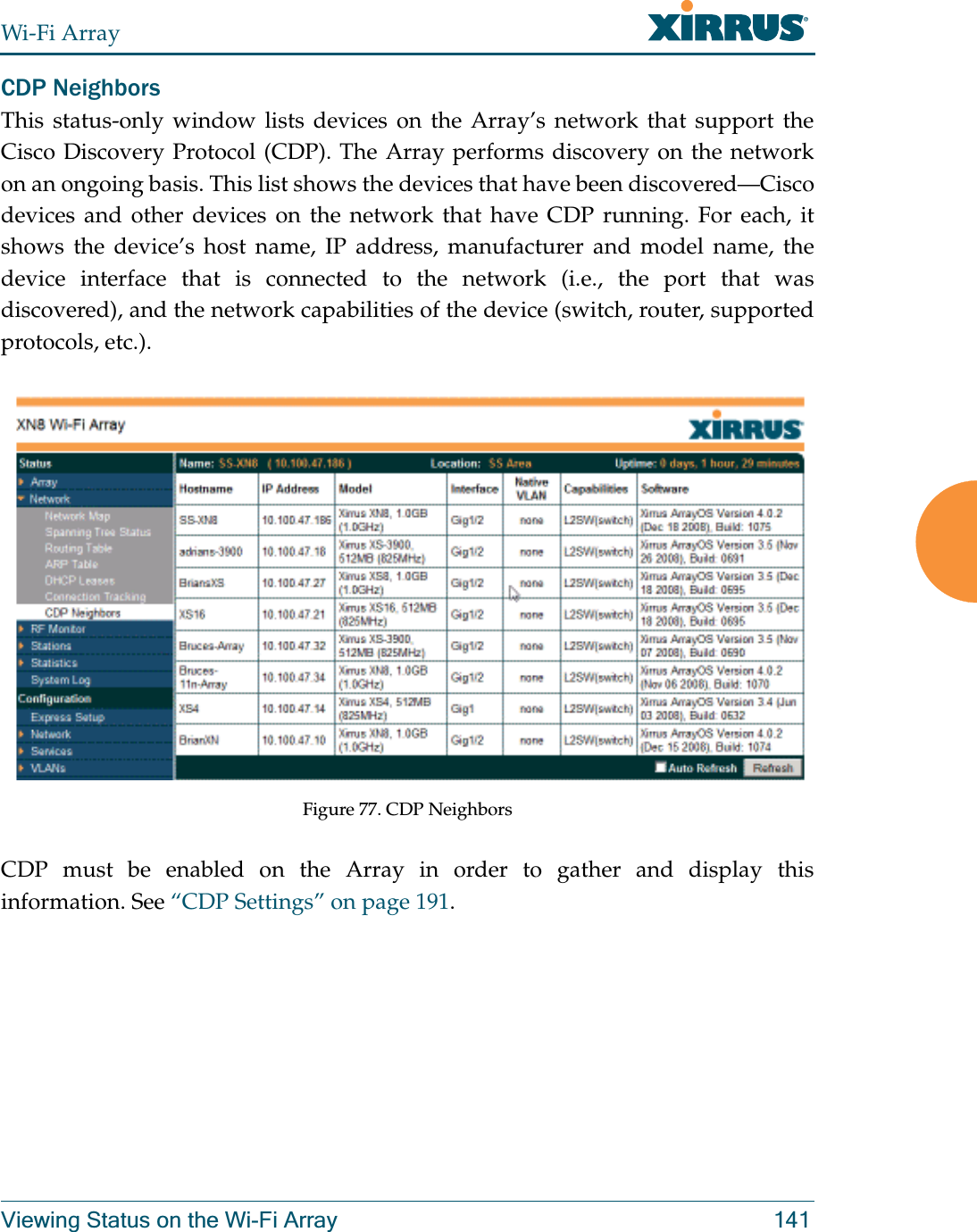
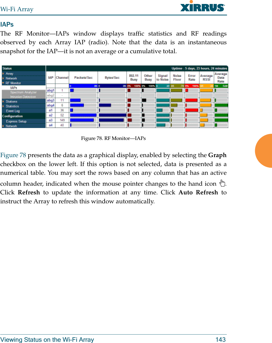
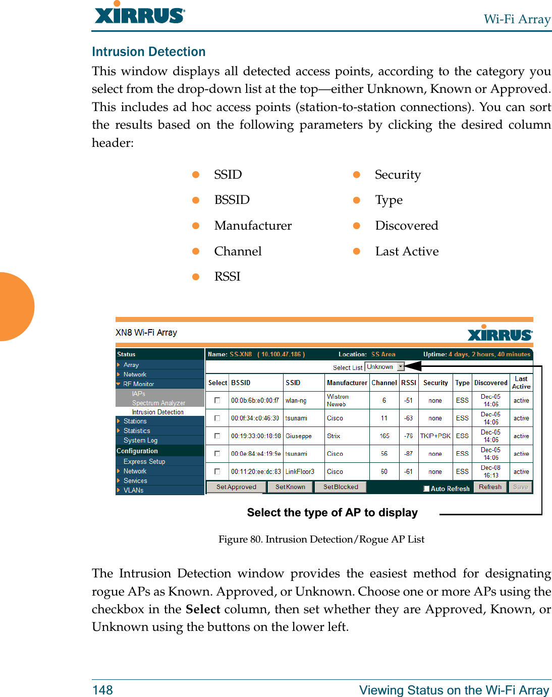
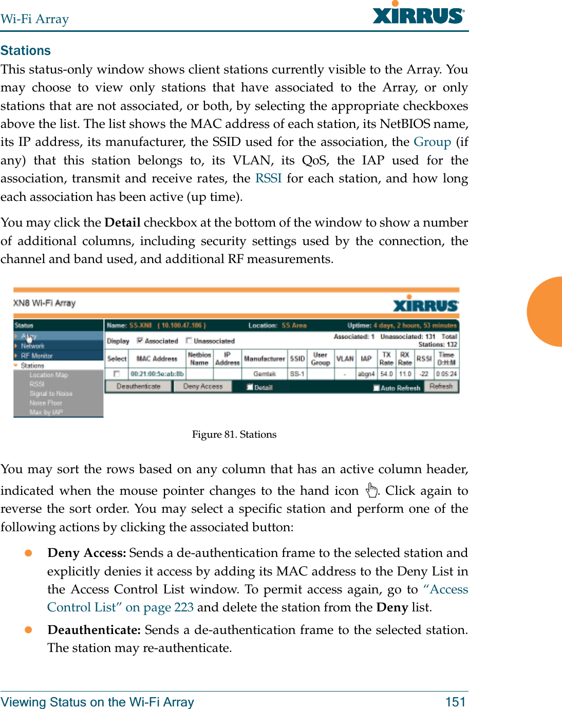
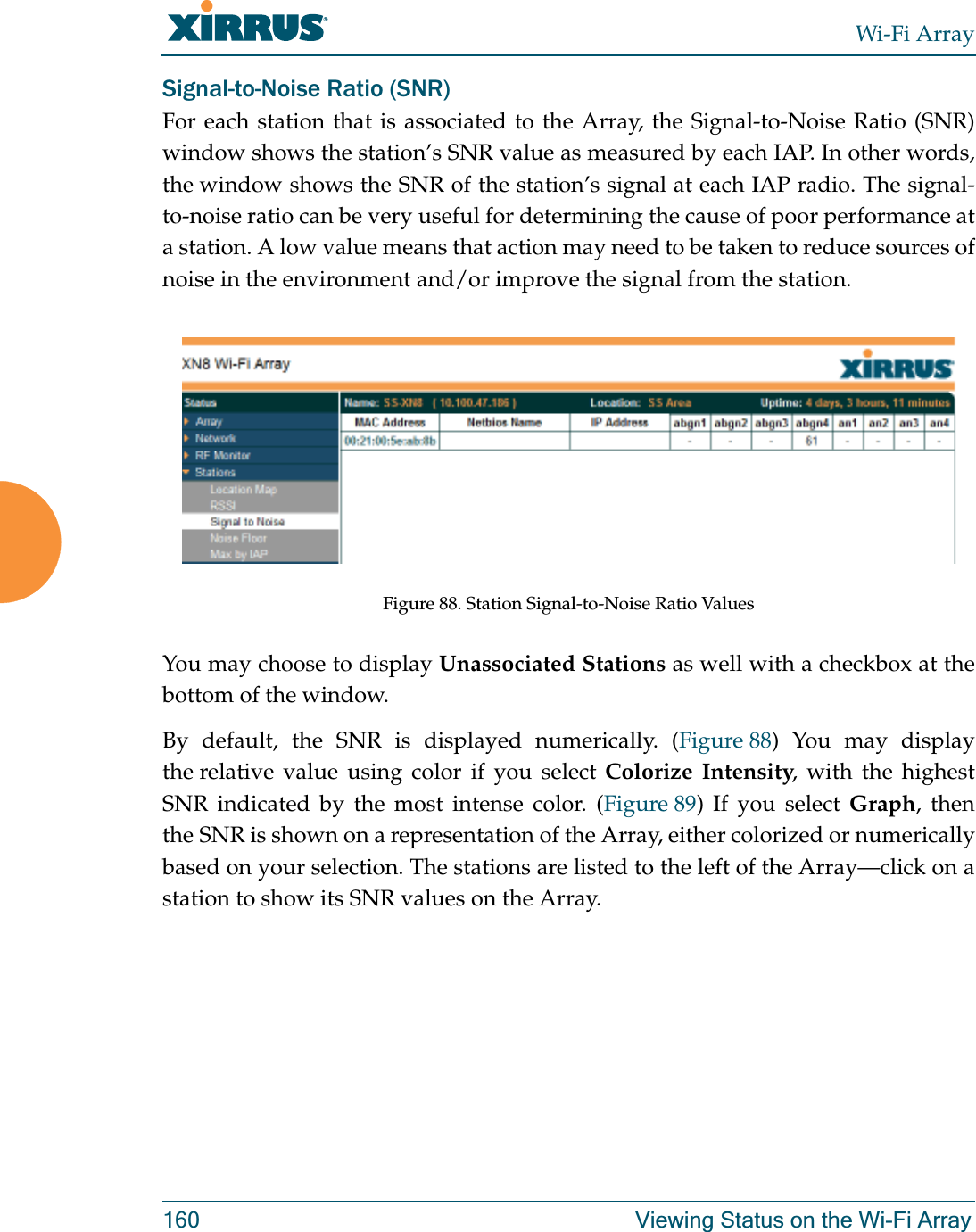
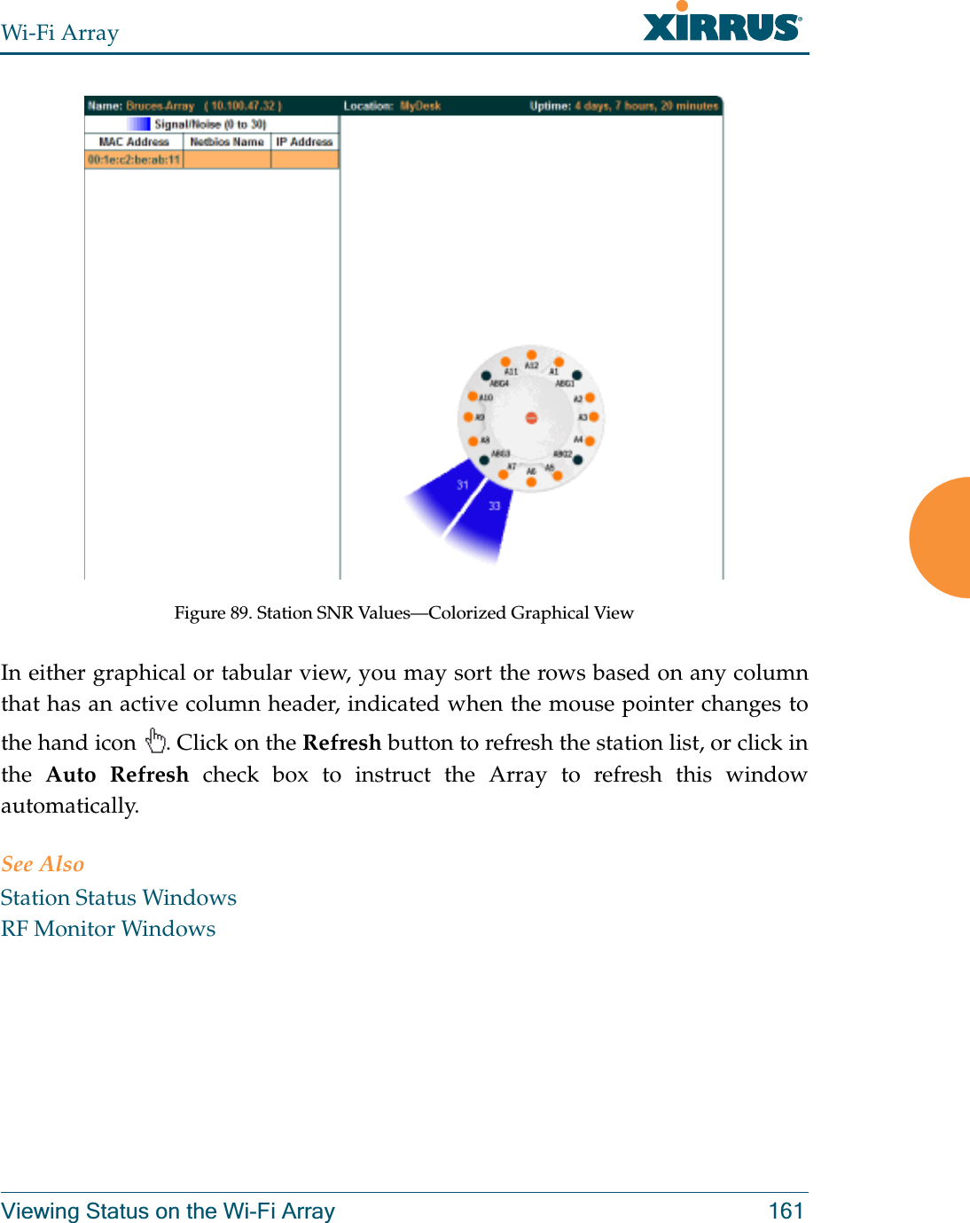
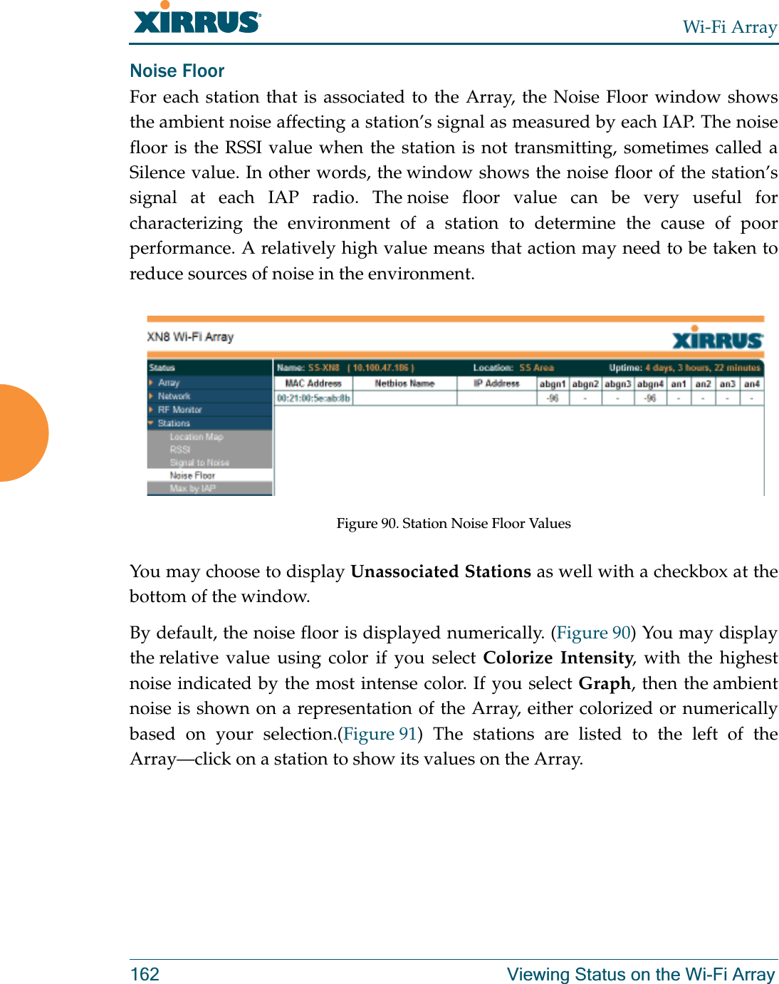
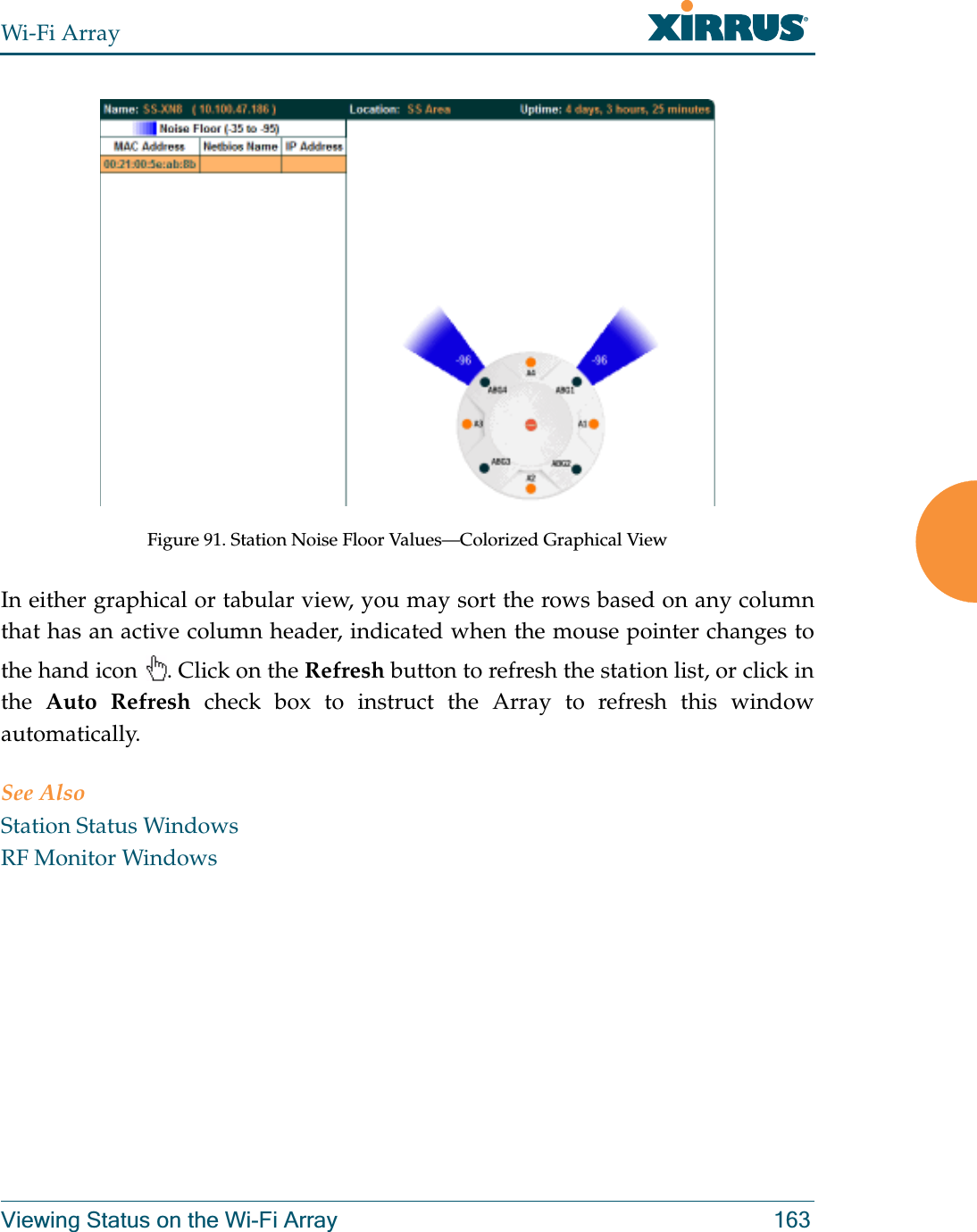
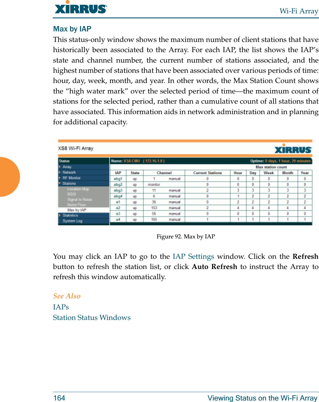
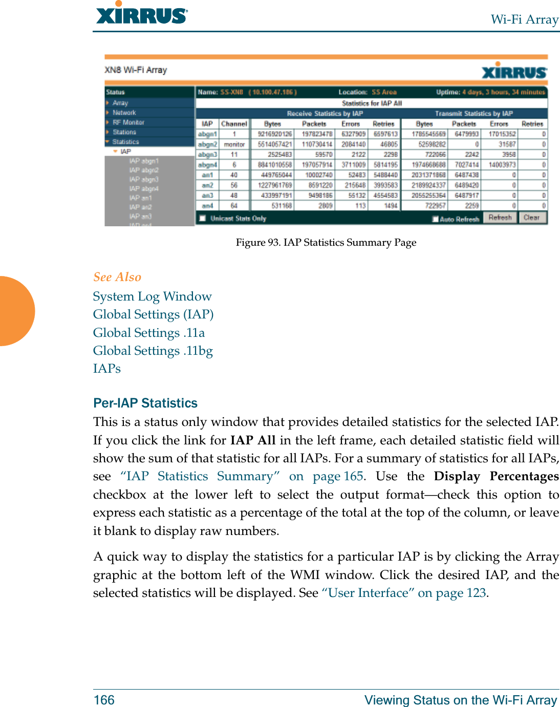
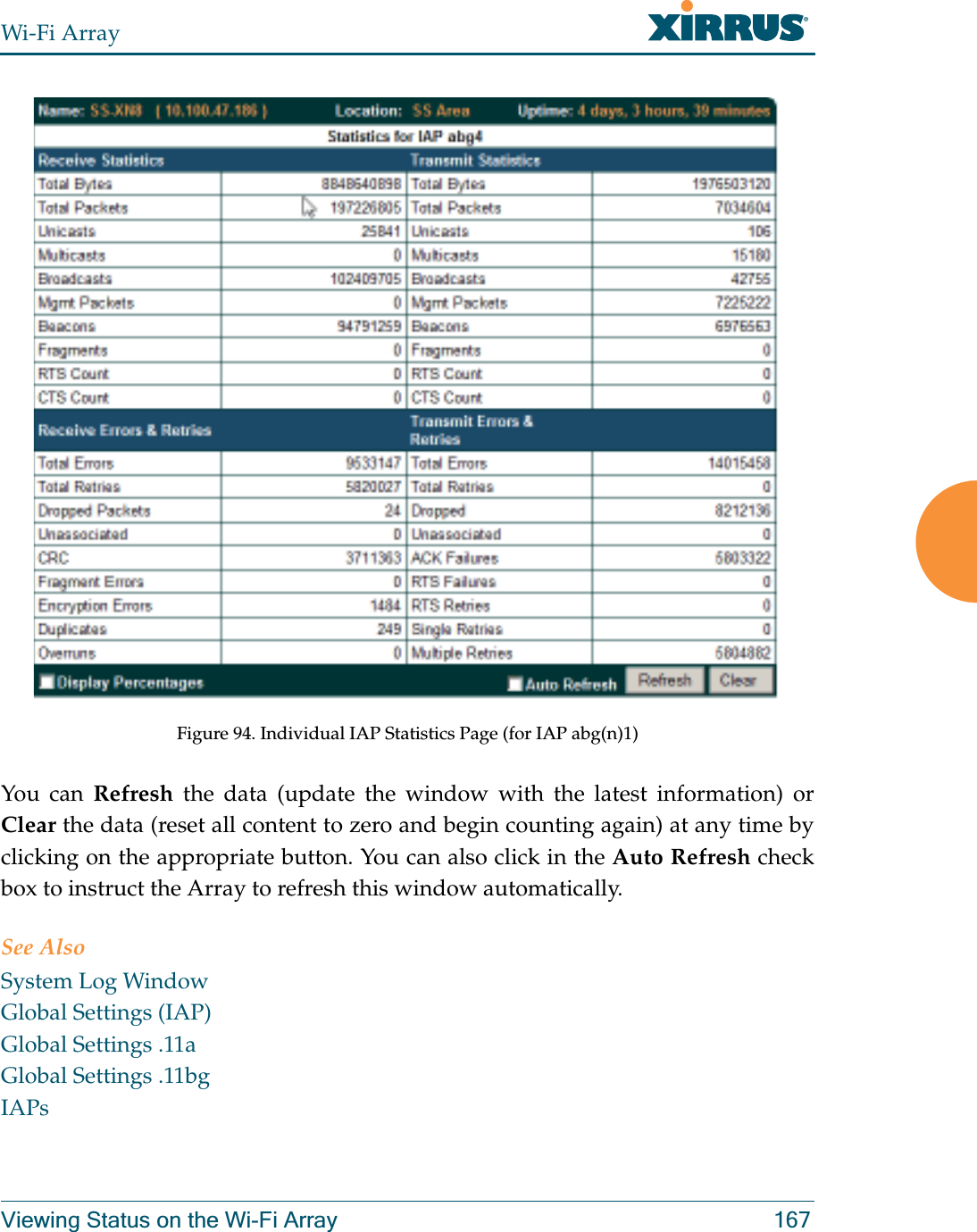
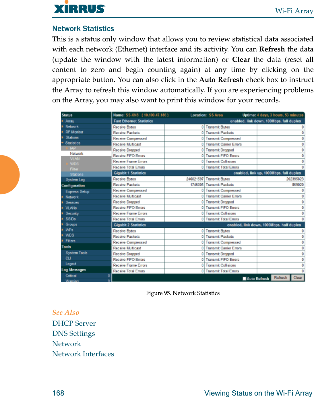
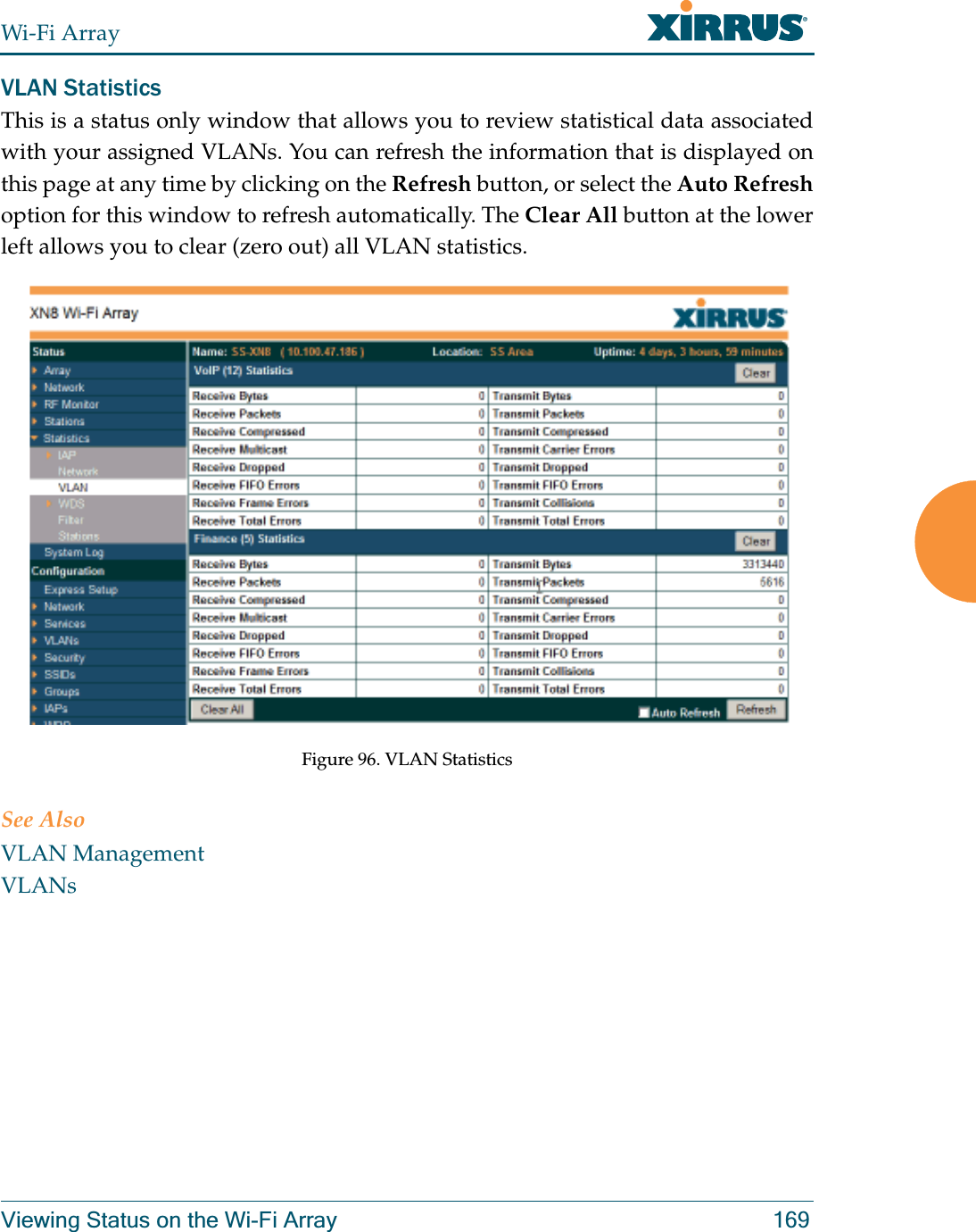
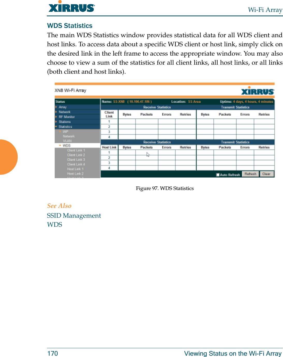
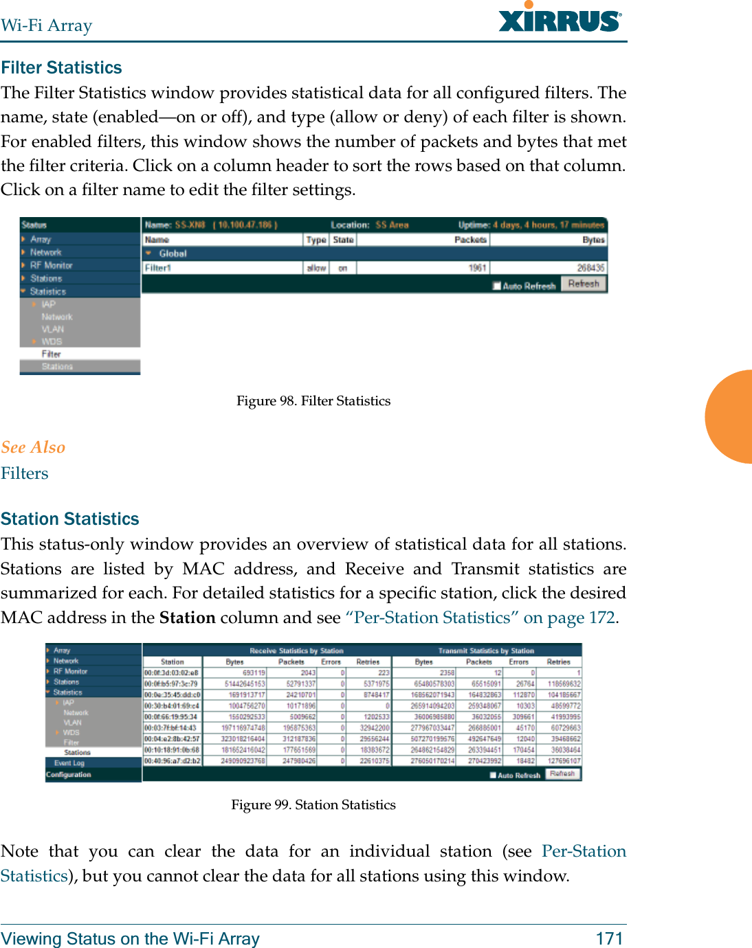
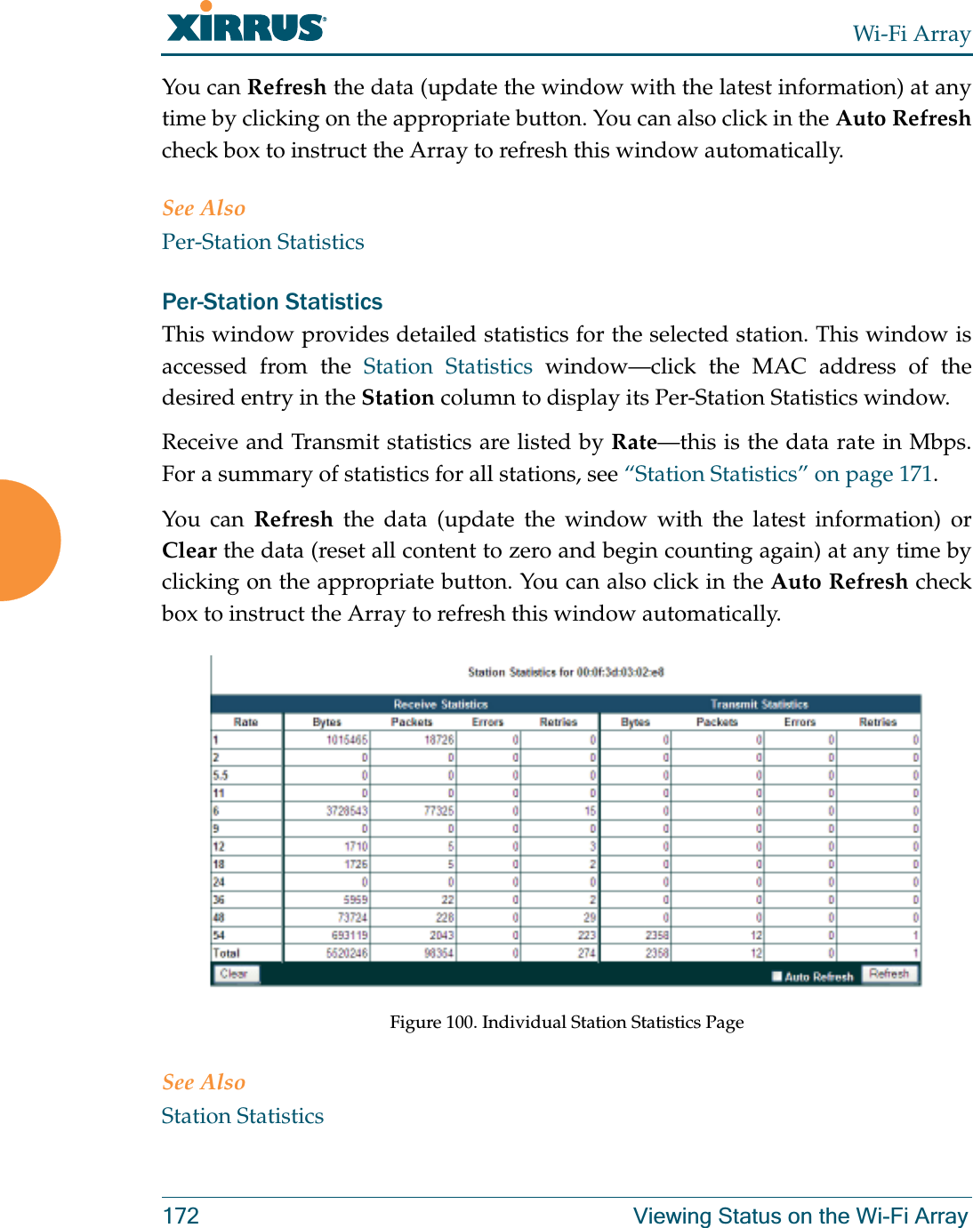
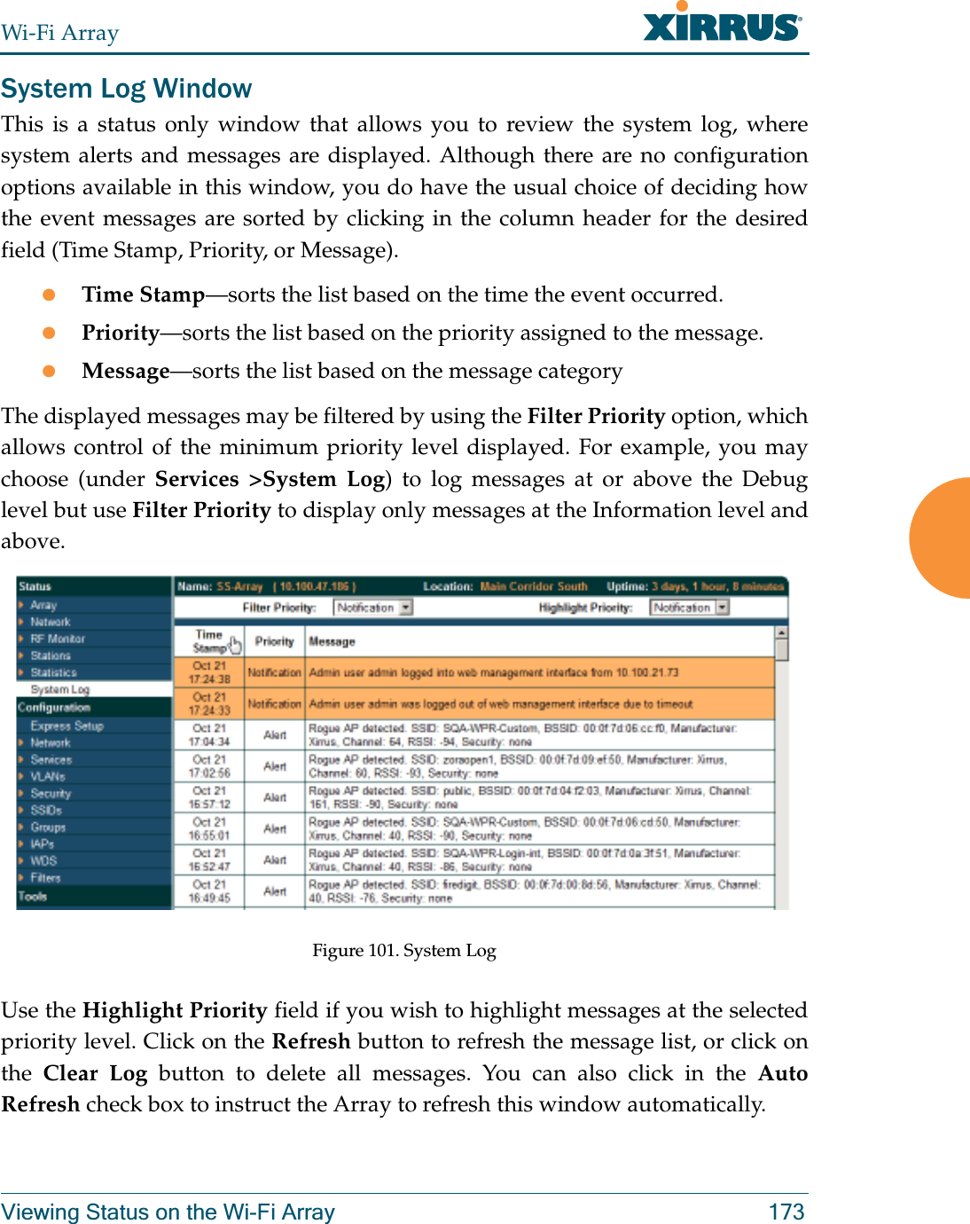
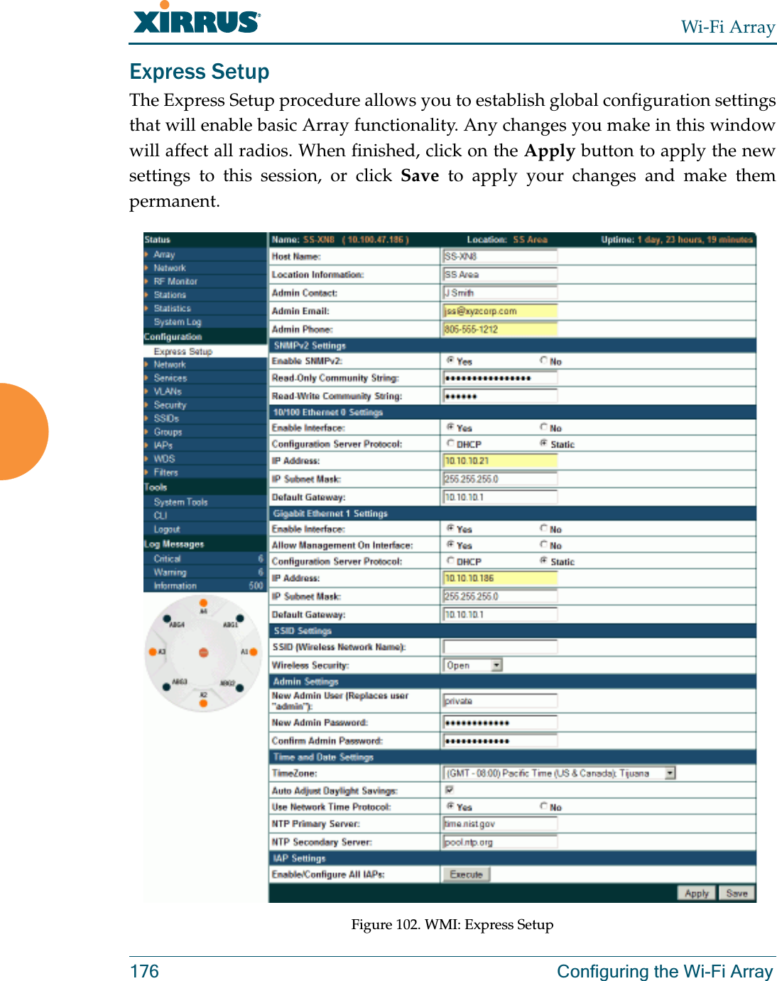
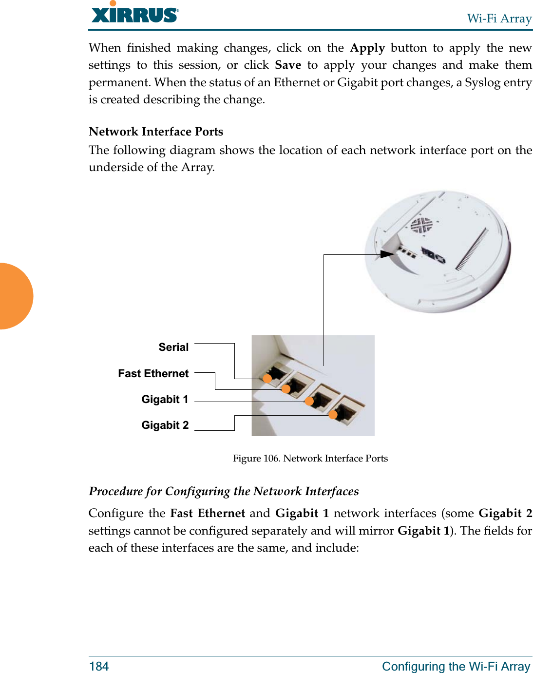
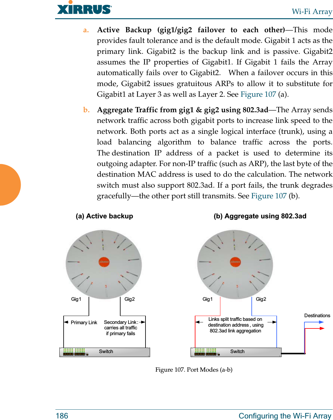
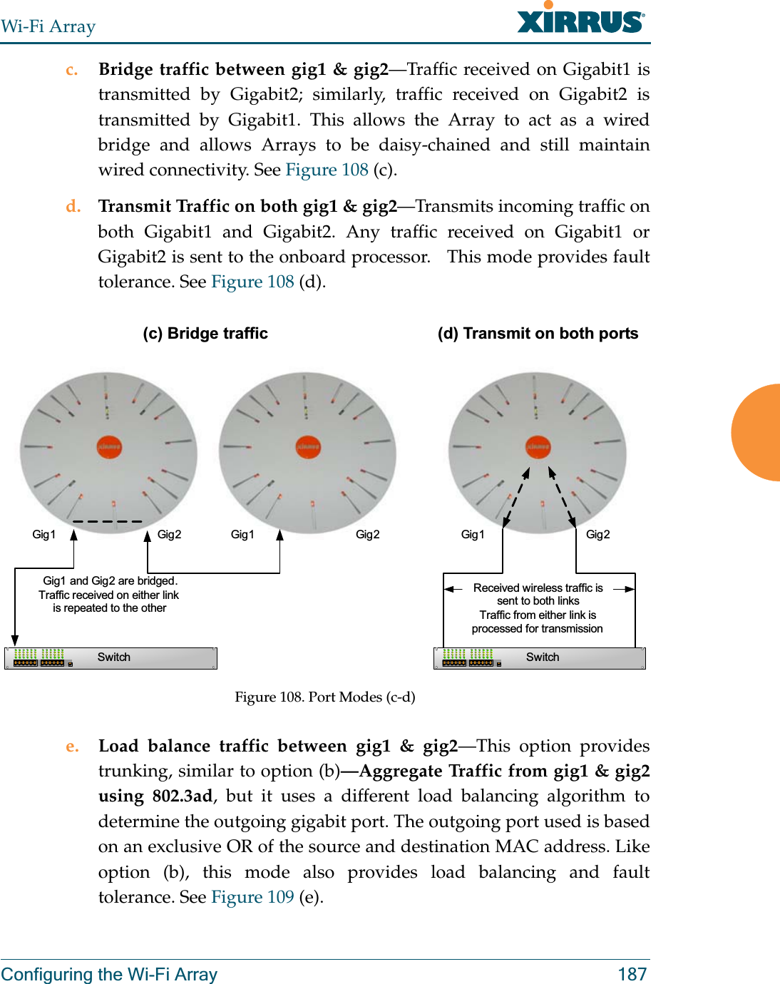
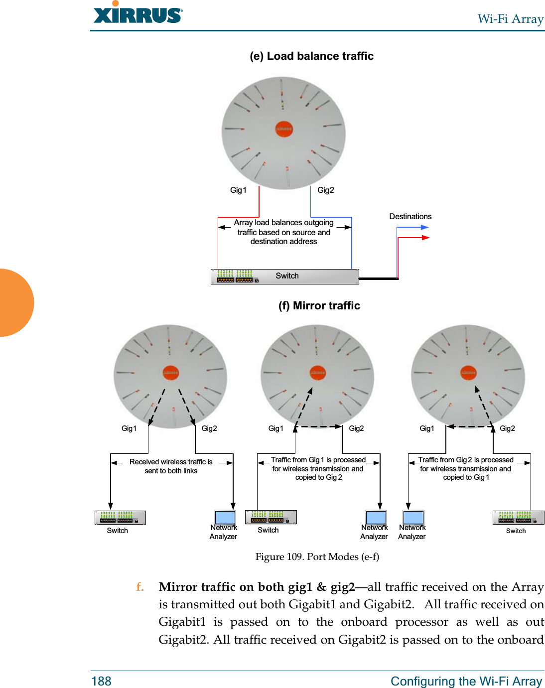
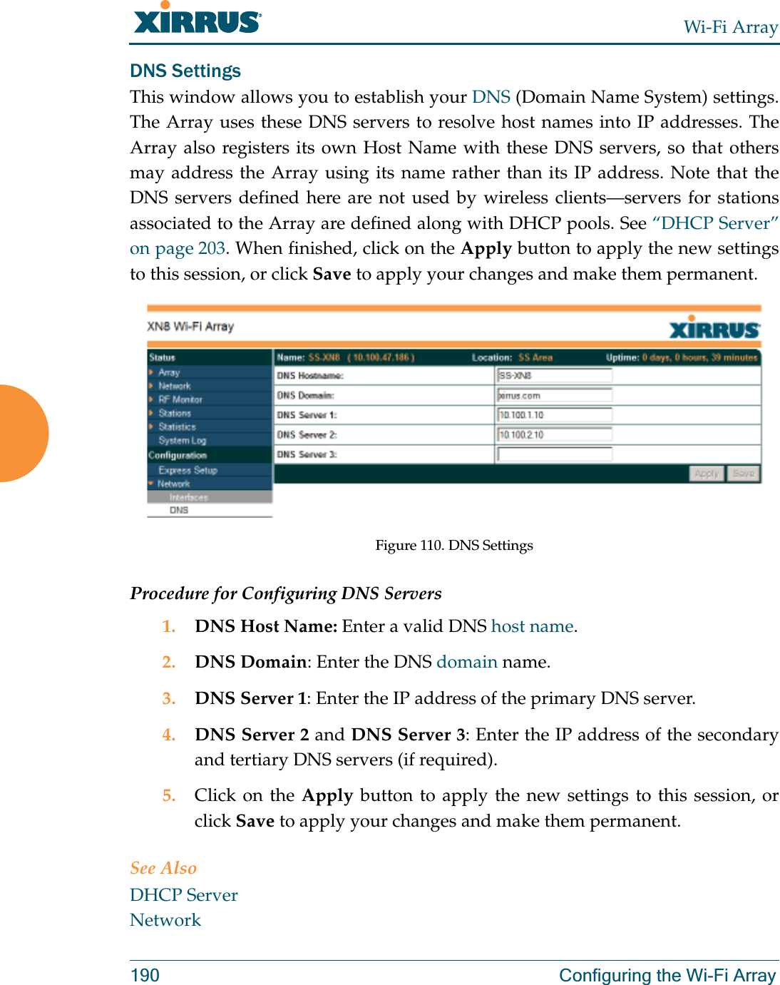
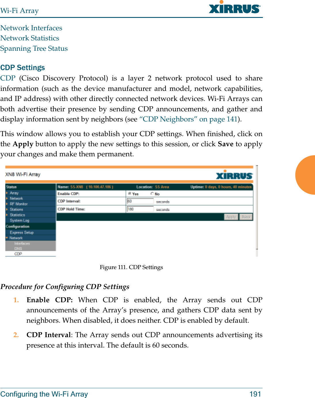
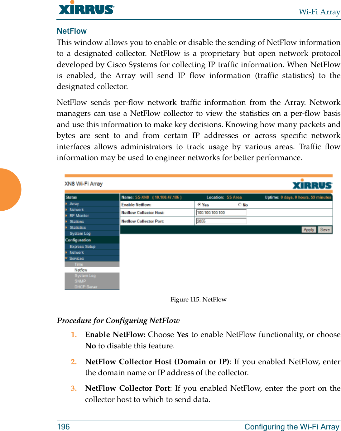
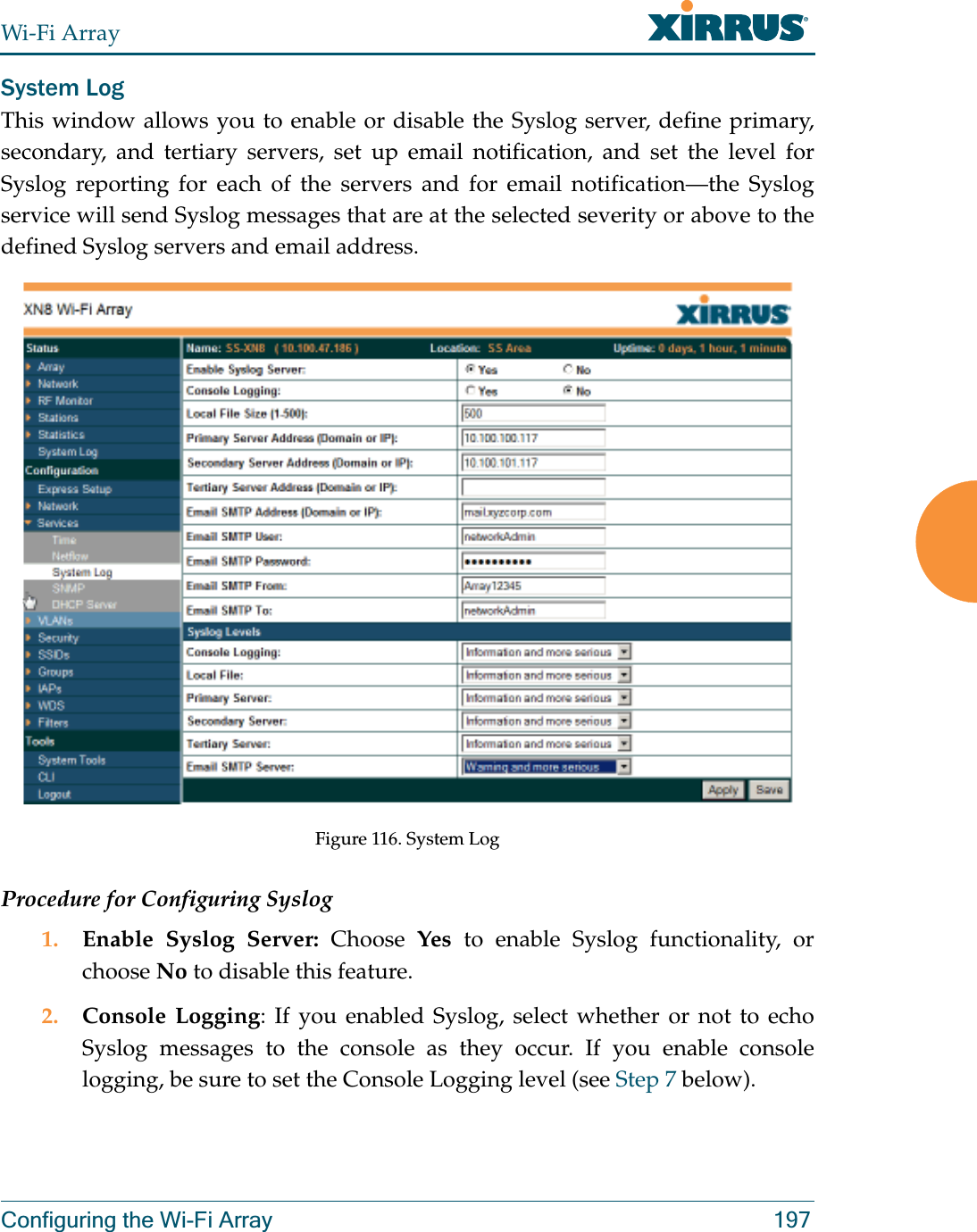
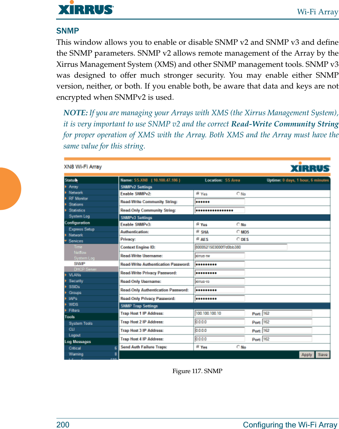
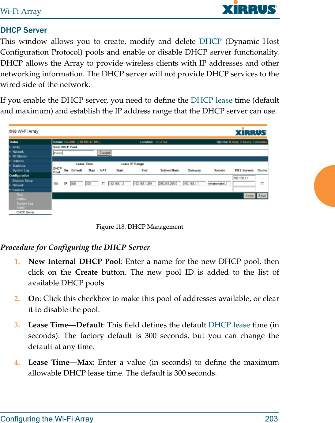
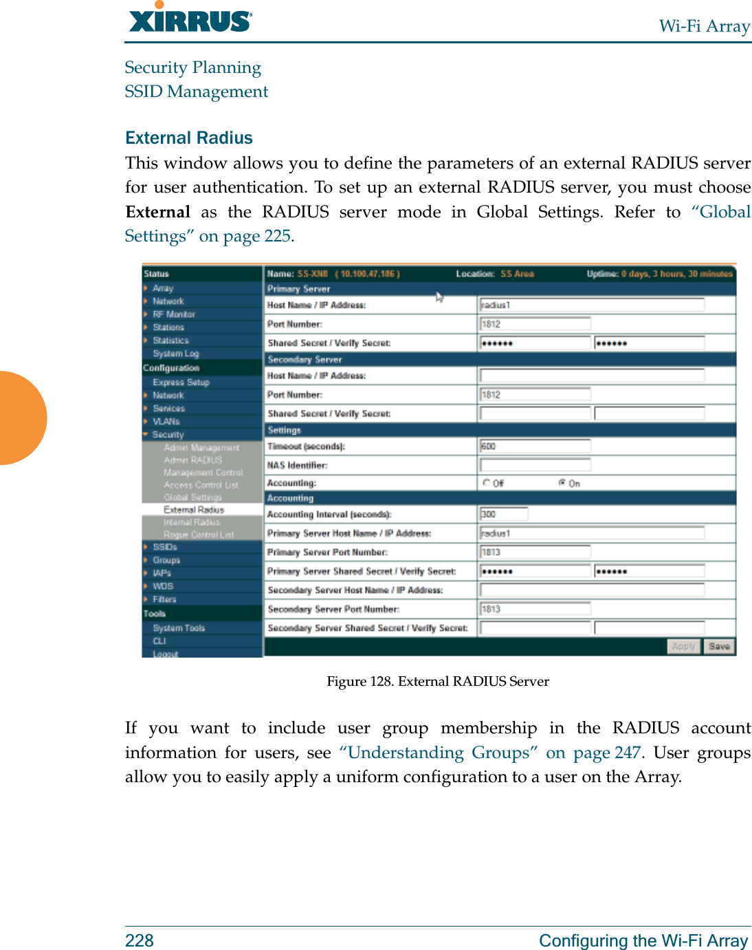
ArrayGuide_Rel4.0_RevW-part 1 of 2

October 28, 2009
All rights reserved. This document may not be reproduced or disclosed in whole or in part by any means without the written consent of Xirrus, Inc.Part Number: 800-0006-001(Revision W) Wi-Fi ArrayXN16, XN12, XN8, XN4XS16, XS12, XS8, XS4XS-3900, XS-3700, XS-3500™
Trademarksis a registered trademark of Xirrus, Inc. All other trademarks and brand names are marks of their respective holders.Please see Legal Notices, Warnings, Compliance Statements, and Warranty and License Agreements in “Appendix F: Notices” on page 433.Xirrus, Inc.2101 Corporate Center DriveThousand Oaks, CA 91320USATel: 1.805.262.16001.800.947.7871 Toll Free in the USFax: 1.866.462.3980www.xirrus.com
Wi-Fi ArrayTable of Contents iTable of ContentsList of Figures.................................................................................... xiiiIntroduction .........................................................................................  1The Xirrus Family of Products ............................................................................... 2Nomenclature .................................................................................................... 4About this User’s Guide .......................................................................................... 4Organization ...................................................................................................... 4Notes and Cautions .......................................................................................... 6Screen Images .................................................................................................... 6Your User’s Guide as a PDF Document  ........................................................ 6Hyperlinks ......................................................................................................... 7Window or Page? .............................................................................................. 7Why Choose the Xirrus Wi-Fi Array? ................................................................... 7Wi-Fi Array Product Overview  ............................................................................. 9Enterprise Class Security ................................................................................. 9Wi-Fi Array Product Family  ......................................................................... 10XN Family of Arrays  ............................................................................... 10XS Family of Arrays  ................................................................................ 11Deployment Flexibility  .................................................................................. 12Power over Gigabit Ethernet (PoGE) (Optional)  ................................ 13Enterprise Class Management  ...................................................................... 14Key Features and Benefits ..................................................................................... 16High Capacity and High Performance ........................................................ 16Extended Coverage ......................................................................................... 17Flexible Coverage Schemes .................................................................... 18Non-Overlapping Channels .......................................................................... 18Secure Wireless Access  .................................................................................. 18Applications Enablement  .............................................................................. 19SDMA Optimization  ...................................................................................... 19Fast Roaming ................................................................................................... 19Easy Deployment ............................................................................................ 19Product Specifications—XN16, XN12, and XN8  ............................................... 20Product Specifications—XN4 ............................................................................... 27
Wi-Fi Arrayii Table of ContentsProduct Specifications—XS16/XS-3900, XS12, and XS8/XS-3700 ........................................................................................................... 34Product Specifications—XS4/XS-3500  ............................................................... 40Installing the Wi-Fi Array ................................................................. 45Installation Prerequisites  ...................................................................................... 45Optional Network Components ................................................................... 47Client Requirements ....................................................................................... 47Planning Your Installation .................................................................................... 48General Deployment Considerations  .......................................................... 48Coverage and Capacity Planning ................................................................. 50Placement .................................................................................................. 50RF Patterns ................................................................................................ 51Capacity and Cell Sizes ........................................................................... 52Fine Tuning Cell Sizes ............................................................................. 53Roaming Considerations  ........................................................................ 54Allocating Channels ................................................................................ 54Deployment Examples ............................................................................ 57IEEE 802.11n Deployment Considerations  ................................................. 59MIMO (Multiple-In Multiple-Out) ........................................................ 60Multiple Data Streams—Spatial Multiplexing .................................... 62Channel Bonding ..................................................................................... 63Improved MAC Throughput ................................................................. 64Short Guard Interval  ............................................................................... 64Obtaining Higher Data Rates ................................................................. 65802.11n Capacity ...................................................................................... 66Failover Planning ............................................................................................ 67Port Failover Protection .......................................................................... 67Switch Failover Protection  ..................................................................... 68Power Planning ............................................................................................... 69AC Power .................................................................................................. 69Power over Gigabit Ethernet  ................................................................. 69Security Planning ............................................................................................ 70Wireless Encryption  ................................................................................ 70Authentication ......................................................................................... 70Meeting PCI DSS Standards ................................................................... 71Meeting FIPS Standards  ......................................................................... 71
Wi-Fi ArrayTable of Contents iiiPort Requirements  .......................................................................................... 72Network Management Planning  .................................................................. 75WDS Planning  ................................................................................................. 76Common Deployment Options  .................................................................... 79Installation Workflow  ........................................................................................... 80Unpacking the Wi-Fi Array .................................................................................. 81Installing Your Wi-Fi Array .................................................................................. 83Choosing a Location ....................................................................................... 83Wiring Considerations ............................................................................ 84Mounting the Array on a Ceiling  ................................................................. 86Attaching the T-Bar Clips to the Template  .......................................... 86Secure the T-Bar Clips to the Ceiling Support Grid  ........................... 87Installing the Mounting Plate  ................................................................ 88Connecting the Cables—AC Option ..................................................... 89Connecting the Cables—PoGE Option  ................................................ 90Attaching the Array to the Mounting Plate ......................................... 92Securing the Array ................................................................................... 94Dismounting the Array ........................................................................... 95Mounting Array on a Wall (All models except 4-port Arrays) ................ 96Kit Contents (Wall Mount Assembly)  .................................................. 96Tools Required ......................................................................................... 96Mark the Wall Position  ........................................................................... 97Install the SNAPTOGGLE™ Toggle Bolts ........................................... 98Attach the Mounting Plate to the Wall Mounting Bracket ................ 99Attach the Wall Mounting Bracket/Plate Assembly to the Wall  ..... 99Mount the Array .................................................................................... 100Mounting the Wi-Fi Array on a Wall (XS4 and XS-3500)  ....................... 101Kit Contents (Wall Mount Assembly)  ................................................ 101Tools Required ....................................................................................... 101Mark the Wall Position  ......................................................................... 102Install the SNAPTOGGLE™ Toggle Bolts ......................................... 102Attach the Mounting Plate to the Wall Mounting Bracket .............. 104Attach the Wall Mounting Bracket/Plate Assembly to the Wall  ... 105Mount the Array .................................................................................... 106Removing the Array .............................................................................. 107Powering Up the Wi-Fi Array ............................................................................ 107Array LED Operating Sequences  ............................................................... 108
Wi-Fi Arrayiv Table of ContentsLED Boot Sequence  ............................................................................... 108LED Operation when Array is Running  ............................................ 109Establishing Communication with the Array .................................................. 110Using the Serial Port ..................................................................................... 110Using the Ethernet Ports .............................................................................. 110Logging In ...................................................................................................... 111Performing the Express Setup Procedure ......................................................... 112Procedure for Performing an Express Setup  ............................................ 113The Web Management Interface ................................................  119An Overview  ........................................................................................................ 120Structure of the WMI ........................................................................................... 121User Interface  ....................................................................................................... 123Utility Buttons ........................................................................................ 124Logging In ............................................................................................................. 126Applying Configuration Changes ..................................................................... 126Viewing Status on the Wi-Fi Array...............................................  127Array Status Windows ........................................................................................ 127Array Summary  ............................................................................................ 128Content of the Array Summary Window  .......................................... 128Array Information  ........................................................................................ 131Array Configuration ..................................................................................... 132Admin History  .............................................................................................. 133Network Status Windows ................................................................................... 133Network Map  ................................................................................................ 134Content of the Network Map Window  .............................................. 134Spanning Tree Status .................................................................................... 136Routing Table  ................................................................................................ 138ARP Table  ...................................................................................................... 138DHCP Leases ................................................................................................. 139Connection Tracking/NAT ......................................................................... 140CDP Neighbors  ............................................................................................. 141RF Monitor Windows .......................................................................................... 142IAPs ................................................................................................................. 143Spectrum Analyzer  ...................................................................................... 144Intrusion Detection  ...................................................................................... 148
Wi-Fi ArrayTable of Contents vStation Status Windows  ...................................................................................... 150Stations ........................................................................................................... 151Location Map ................................................................................................. 152RSSI ................................................................................................................. 158Signal-to-Noise Ratio (SNR) ........................................................................ 160Noise Floor ..................................................................................................... 162Max by IAP  .................................................................................................... 164Statistics Windows ............................................................................................... 165IAP Statistics Summary ................................................................................ 165Per-IAP Statistics ........................................................................................... 166Network Statistics ......................................................................................... 168VLAN Statistics ............................................................................................. 169WDS Statistics ................................................................................................ 170Filter Statistics  ............................................................................................... 171Station Statistics  ............................................................................................ 171Per-Station Statistics  ..................................................................................... 172System Log Window  ........................................................................................... 173Configuring the Wi-Fi Array ..........................................................  175Express Setup ........................................................................................................ 176Network ................................................................................................................. 182Network Interfaces   ...................................................................................... 183Network Interface Ports ........................................................................ 184DNS Settings .................................................................................................. 190CDP Settings .................................................................................................. 191Services .................................................................................................................. 193Time Settings (NTP)  ..................................................................................... 194NetFlow .......................................................................................................... 196System Log ..................................................................................................... 197SNMP .............................................................................................................. 200DHCP Server  ................................................................................................. 203VLANs ................................................................................................................... 205Understanding Virtual Tunnels  .......................................................... 205VLAN Management  ..................................................................................... 207Security .................................................................................................................. 209Understanding Security ........................................................................ 210Certificates and Connecting Securely to the WMI ............................ 213
Wi-Fi Arrayvi Table of ContentsUsing the Array’s Default Certificate  ................................................. 213Using an External Certificate Authority ............................................. 214Admin Management  .................................................................................... 215Admin RADIUS  ............................................................................................ 216About Creating Admin Accounts on the RADIUS Server  .............. 217Management Control  ................................................................................... 219Access Control List ....................................................................................... 223Global Settings  .............................................................................................. 225External Radius ............................................................................................. 228Internal Radius .............................................................................................. 231Rogue Control List ........................................................................................ 233SSIDs ...................................................................................................................... 235Understanding SSIDs ............................................................................ 236Understanding QoS Priority on the Wi-Fi Array .............................. 237SSID Management  ........................................................................................ 240SSID List (top of page)  .......................................................................... 240SSID Limits  ............................................................................................. 243Web Page Redirect Configuration Settings ........................................ 244Groups ................................................................................................................... 247Understanding Groups ......................................................................... 247Using Groups  ......................................................................................... 248Group Management  ..................................................................................... 249Group Limits  .......................................................................................... 251IAPs ........................................................................................................................ 253Understanding Fast Roaming .............................................................. 254IAP Settings  ................................................................................................... 255Global Settings (IAP)  ................................................................................... 260Beacon Configuration  ........................................................................... 262Station Management  ............................................................................. 262Advanced Traffic Optimization  .......................................................... 263Global Settings .11a  ...................................................................................... 267Global Settings .11bg .................................................................................... 269Global Settings .11n  ...................................................................................... 273Advanced RF Settings .................................................................................. 275About Standby Mode ............................................................................ 275About Blocking Rogue APs .................................................................. 276RF Intrusion Detection .......................................................................... 277
Wi-Fi ArrayTable of Contents viiRF Resilience  .......................................................................................... 278RF Power & Sensitivity ......................................................................... 279RF Spectrum Management ................................................................... 280LED Settings  .................................................................................................. 283WDS ....................................................................................................................... 285About Configuring WDS Links ........................................................... 285WDS Client Links .......................................................................................... 287Filters ..................................................................................................................... 289Filter Lists  ...................................................................................................... 290Filter Management  ....................................................................................... 291Using Tools on the Wi-Fi Array.....................................................  295System Tools ......................................................................................................... 296System ..................................................................................................... 297Configuration ......................................................................................... 298Diagnostics ............................................................................................. 299Web Page Redirect ................................................................................. 300Tools ........................................................................................................ 301Progress and Status Frames  ................................................................. 303CLI  ......................................................................................................................... 303Logout .................................................................................................................... 305The Command Line Interface......................................................  307Establishing a Secure Shell (SSH) Connection ................................................. 307Getting Started with the CLI  .............................................................................. 309Inputting Commands ................................................................................... 309Getting Help  .................................................................................................. 309Top Level Commands  ......................................................................................... 311Root Command Prompt ............................................................................... 311configure Commands ................................................................................... 312show Commands  .......................................................................................... 315statistics Commands ..................................................................................... 318Configuration Commands .................................................................................. 320acl .................................................................................................................... 320admin .............................................................................................................. 321cdp ................................................................................................................... 322clear ................................................................................................................. 323
Wi-Fi Arrayviii Table of Contentscontact-info .................................................................................................... 324date-time ........................................................................................................ 325dhcp-server .................................................................................................... 326dns ................................................................................................................... 327file .................................................................................................................... 328filter ................................................................................................................. 331fips ................................................................................................................... 333group .............................................................................................................. 334hostname ........................................................................................................ 334https ................................................................................................................ 335interface .......................................................................................................... 336license ............................................................................................................. 337load ................................................................................................................. 337location ........................................................................................................... 338management .................................................................................................. 338more ................................................................................................................ 338netflow ............................................................................................................ 339no ..................................................................................................................... 340pci-audit ......................................................................................................... 342quit .................................................................................................................. 343radius-server .................................................................................................. 343reboot .............................................................................................................. 344reset ................................................................................................................. 344run-tests .......................................................................................................... 345security ........................................................................................................... 347snmp ............................................................................................................... 348ssh .................................................................................................................... 348ssid .................................................................................................................. 350standby ........................................................................................................... 350syslog .............................................................................................................. 351telnet ............................................................................................................... 353uptime ............................................................................................................. 353vlan .................................................................................................................. 354Sample Configuration Tasks  .............................................................................. 355Configuring a Simple Open Global SSID .................................................. 356Configuring a Global SSID using WPA-PEAP ......................................... 357Configuring an SSID-Specific SSID using WPA-PEAP ........................... 358
Wi-Fi ArrayTable of Contents ixEnabling Global IAPs ................................................................................... 359Disabling Global IAPs .................................................................................. 360Enabling a Specific IAP ................................................................................ 361Disabling a Specific IAP ............................................................................... 362Setting Cell Size Auto-Configuration for All IAPs  .................................. 363Setting the Cell Size for All IAPs ................................................................ 364Setting the Cell Size for a Specific IAP ....................................................... 365Configuring VLANs on an Open SSID ...................................................... 366Configuring Radio Assurance Mode (Loopback Tests) .......................... 367Appendices.....................................................................................  369Appendix A: Servicing the Wi-Fi Array  ............................................................. 371Removing the Access Panel ................................................................................ 373Reinstalling the Access Panel ............................................................................. 376Replacing the FLASH Memory Module ........................................................... 378Replacing the Main System Memory ................................................................ 380Replacing the Integrated Access Point Radio Module  ................................... 382Replacing the Power Supply Module  ............................................................... 385Appendix B: Quick Reference Guide  ............................................................... 387Factory Default Settings ...................................................................................... 387Host Name ..................................................................................................... 387Network Interfaces  ....................................................................................... 387Serial ........................................................................................................ 387Gigabit 1 and Gigabit 2 ......................................................................... 388Fast Ethernet ........................................................................................... 388Integrated Access Points (IAPs) .................................................................. 389Server Settings ............................................................................................... 390NTP .......................................................................................................... 390Syslog ...................................................................................................... 390SNMP ...................................................................................................... 390DHCP .............................................................................................................. 391Default SSID  .................................................................................................. 391Security  .......................................................................................................... 392Global Settings - Encryption   ............................................................... 392External RADIUS (Global)   .................................................................. 392Internal RADIUS .................................................................................... 393
Wi-Fi Arrayx Table of ContentsAdministrator Account and Password ...................................................... 394Management .................................................................................................. 394Keyboard Shortcuts  ............................................................................................. 394Appendix C: Technical Support  ........................................................................ 397General Hints and Tips  ....................................................................................... 397Frequently Asked Questions .............................................................................. 398Multiple SSIDs ............................................................................................... 398Security ........................................................................................................... 400VLAN Support .............................................................................................. 403Array Monitor and Radio Assurance Capabilities .......................................... 406Enabling Monitoring on the Array  ..................................................... 406How Monitoring Works ............................................................................... 406Radio Assurance  ........................................................................................... 407Radio Assurance Options ..................................................................... 408Upgrading the Array via CLI ............................................................................. 409Sample Output for the Upgrade Procedure: ............................................. 410Power over Gigabit Ethernet Compatibility Matrix  ....................................... 414Determining If an XS-3700 or XS-3900 is Modified for PoGE ......... 416Contact Information  ............................................................................................ 417Appendix D: Implementing PCI DSS  ............................................................... 419Payment Card Industry Data Security Standard Overview .......................... 419PCI DSS and Wireless .......................................................................................... 420The Xirrus Array PCI Compliance Configuration  .......................................... 421The pci-audit Command ..................................................................................... 422Additional Resources  .......................................................................................... 423Appendix E: Implementing FIPS Security  ....................................................... 425Appendix F: Notices  ........................................................................................... 433Notices ................................................................................................................... 433EU Directive 1999/5/EC Compliance Information ........................................ 436Safety Warnings  ................................................................................................... 443Translated Safety Warnings  ............................................................................... 444Software Warranty and License Agreement .................................................... 445Hardware Warranty Agreement  ....................................................................... 452
Wi-Fi ArrayTable of Contents xiGlossary of Terms..........................................................................  455Index................................................................................................  467
Wi-Fi Arrayxii Table of Contents
Wi-Fi ArrayList of Figures xiiiList of FiguresFigure 1. Xirrus Arrays............................................................................................... 2Figure 2. The Xirrus Management System .............................................................. 3Figure 3. Wi-Fi Array (XN16).................................................................................... 9Figure 4. Wireless Coverage Patterns .................................................................... 12Figure 5. XP8 - Power over Ethernet Usage .......................................................... 13Figure 6. WMI: Array Status.................................................................................... 14Figure 7. Layout of IAPs (XN16)............................................................................. 16Figure 8. Naming of IAPs (XS16)............................................................................ 17Figure 9. Coverage Schemes ................................................................................... 18Figure 10. Wall Thickness Considerations .............................................................. 49Figure 11. Unit Placement.......................................................................................... 50Figure 12. Full (Normal) Coverage........................................................................... 51Figure 13. Adjusting RF Patterns.............................................................................. 51Figure 14. Custom Coverage ..................................................................................... 52Figure 15. Connection Rate vs. Distance.................................................................. 52Figure 16. Transmit Power......................................................................................... 53Figure 17. Overlapping Cells..................................................................................... 54Figure 18. Allocating Channels Manually............................................................... 56Figure 19. Deployment Scenario (54 Mbps)—Per Sector ...................................... 57Figure 20. Deployment Scenario (36 Mbps)—Per Sector ...................................... 57Figure 21. Deployment Scenario (18 Mbps)—Per Sector ...................................... 58Figure 22. Classic 802.11 Signal Transmission........................................................ 60Figure 23. MIMO Signal Processing......................................................................... 61Figure 24. Spatial Multiplexing................................................................................. 62Figure 25. Channel Bonding...................................................................................... 63Figure 26. MAC Throughput Improvements.......................................................... 64Figure 27. Computing 802.11n Data Rates .............................................................. 65Figure 28. 802.11n Increases Capacity...................................................................... 66Figure 29. Port Failover Protection........................................................................... 67Figure 30. Switch Failover Protection ...................................................................... 68Figure 31. Port Requirements for XMS .................................................................... 72Figure 32. WDS Link................................................................................................... 76Figure 33. A Multiple Hop WDS Connection ......................................................... 77Figure 34. WDS Failover Protection ......................................................................... 77
Wi-Fi Arrayxiv List of FiguresFigure 35. Installation Workflow .............................................................................. 80Figure 36. Array Placement ....................................................................................... 83Figure 37. Attaching the T-Bar Clips to the Template ........................................... 86Figure 38. Attaching the T-Bar Clips to the Ceiling Grid...................................... 87Figure 39. Installing the Mounting Plate ................................................................. 88Figure 40. Connecting the Cables ............................................................................. 89Figure 41. Connecting the Cables (PoGE—XS8/XS12/XS16) .............................. 90Figure 42. Connecting the Cable (PoGE—XS4) ...................................................... 91Figure 43. Attaching the Unit (XS4 shown)............................................................. 92Figure 44. Attaching the Unit (XS-3900) .................................................................. 93Figure 45. Securing the Array.................................................................................... 94Figure 46. IAP Positions (XS16 shown).................................................................... 95Figure 47. Wall Mount—Marking the Holes........................................................... 97Figure 48. Installing the Toggle Bolts....................................................................... 98Figure 49. Attaching the Wall Mounting Plate ....................................................... 99Figure 50. Mounting the Array on a Wall ............................................................. 100Figure 51. Wall Mount—Marking the Holes......................................................... 102Figure 52. Installing the Toggle Bolts..................................................................... 103Figure 53. Attaching the Array Mounting Plate................................................... 104Figure 54. Attaching the Wall Mounting Bracket to the Wall ............................ 105Figure 55. Mounting the Array on a Wall ............................................................. 106Figure 56. LED Locations (XS-3900) ....................................................................... 107Figure 57. Network Interface Ports......................................................................... 110Figure 58. Express Setup.......................................................................................... 112Figure 59. LEDs are Switched On........................................................................... 117Figure 60. Web Management Interface.................................................................. 120Figure 61. WMI: Frames........................................................................................... 123Figure 62. WMI: Utility Buttons.............................................................................. 124Figure 63. Feedback Form........................................................................................ 125Figure 64. Logging In to the Wi-Fi Array .............................................................. 126Figure 65. Array Summary ...................................................................................... 128Figure 66. Disabled IAP (Partial View).................................................................. 129Figure 67. IAP Cells .................................................................................................. 130Figure 68. Array Information .................................................................................. 131Figure 69. Show Configuration ............................................................................... 132Figure 70. Admin Login History............................................................................. 133Figure 71. Network Map.......................................................................................... 134
Wi-Fi ArrayList of Figures xvFigure 72. Spanning Tree Status.............................................................................. 137Figure 73. Routing Table.......................................................................................... 138Figure 74. ARP Table ................................................................................................ 138Figure 75. DHCP Leases........................................................................................... 139Figure 76. Connection Tracking.............................................................................. 140Figure 77. CDP Neighbors....................................................................................... 141Figure 78. RF Monitor—IAPs.................................................................................. 143Figure 79. RF Spectrum Analyzer........................................................................... 145Figure 80. Intrusion Detection/Rogue AP List..................................................... 148Figure 81. Stations..................................................................................................... 151Figure 82. Location Map........................................................................................... 153Figure 83. Controls for Location Map.................................................................... 154Figure 84. Minimizing stations................................................................................ 155Figure 85. Setting Array location on a Custom Image......................................... 157Figure 86. Station RSSI Values ................................................................................ 158Figure 87. Station RSSI Values—Colorized Graphical View .............................. 159Figure 88. Station Signal-to-Noise Ratio Values................................................... 160Figure 89. Station SNR Values—Colorized Graphical View .............................. 161Figure 90. Station Noise Floor Values.................................................................... 162Figure 91. Station Noise Floor Values—Colorized Graphical View.................. 163Figure 92. Max by IAP.............................................................................................. 164Figure 93. IAP Statistics Summary Page................................................................ 166Figure 94. Individual IAP Statistics Page (for IAP abg(n)1) ............................... 167Figure 95. Network Statistics................................................................................... 168Figure 96. VLAN Statistics....................................................................................... 169Figure 97. WDS Statistics ......................................................................................... 170Figure 98. Filter Statistics ......................................................................................... 171Figure 99. Station Statistics ...................................................................................... 171Figure 100. Individual Station Statistics Page......................................................... 172Figure 101. System Log  ............................................................................................. 173Figure 102. WMI: Express Setup............................................................................... 176Figure 103. LEDs are Switched On........................................................................... 181Figure 104. Network Interfaces................................................................................. 182Figure 105. Network Settings .................................................................................... 183Figure 106. Network Interface Ports......................................................................... 184Figure 107. Port Modes (a-b) ..................................................................................... 186Figure 108. Port Modes (c-d) ..................................................................................... 187
Wi-Fi Arrayxvi List of FiguresFigure 109. Port Modes (e-f) ...................................................................................... 188Figure 110. DNS Settings............................................................................................ 190Figure 111. CDP Settings............................................................................................ 191Figure 112. Services..................................................................................................... 193Figure 113. Time Settings (Manual Time)................................................................ 194Figure 114. Time Settings (NTP Time Enabled)...................................................... 195Figure 115. NetFlow.................................................................................................... 196Figure 116. System Log .............................................................................................. 197Figure 117. SNMP ....................................................................................................... 200Figure 118. DHCP Management............................................................................... 203Figure 119. VLANs...................................................................................................... 205Figure 120. VLAN Management............................................................................... 207Figure 121. Security..................................................................................................... 209Figure 122. Import Xirrus Certificate Authority..................................................... 214Figure 123. Admin Management .............................................................................. 215Figure 124. Admin RADIUS...................................................................................... 217Figure 125. Management Control ............................................................................. 219Figure 126. Access Control List................................................................................. 223Figure 127. Global Settings (Security) ...................................................................... 225Figure 128. External RADIUS Server ....................................................................... 228Figure 129. Internal RADIUS Server ........................................................................ 231Figure 130. Rogue Control List ................................................................................. 233Figure 131. SSIDs......................................................................................................... 235Figure 132. Four Traffic Classes................................................................................ 237Figure 133. SSID Management.................................................................................. 240Figure 134. WPR Internal Splash Page Fields (SSID Management)..................... 245Figure 135. Groups...................................................................................................... 247Figure 136. Group Management ............................................................................... 249Figure 137. IAPs........................................................................................................... 253Figure 138. IAP Settings ............................................................................................. 255Figure 139. Global Settings (IAPs)............................................................................ 260Figure 140. Global Settings .11a ................................................................................ 267Figure 141. Global Settings .11bg.............................................................................. 269Figure 142. Global Settings .11n................................................................................ 273Figure 143. Advanced RF Settings............................................................................ 275Figure 144. LED Settings............................................................................................ 283Figure 145. WDS.......................................................................................................... 285
Wi-Fi ArrayList of Figures xviiFigure 146. .Configuring a WDS Link...................................................................... 286Figure 147. WDS Client Links ................................................................................... 287Figure 148. Filters........................................................................................................ 289Figure 149. Filter Lists ................................................................................................ 290Figure 150. Filter Management ................................................................................. 291Figure 151. System Tools............................................................................................ 296Figure 152. Saving the Diagnostic Log..................................................................... 299Figure 153. Managing WPR Splash/Login page files............................................ 300Figure 154. System Command (Ping)....................................................................... 301Figure 155. Radius Ping Output................................................................................ 302Figure 156. CLI Window............................................................................................ 304Figure 157. Login Window ........................................................................................ 305Figure 158. Logging In................................................................................................ 308Figure 159. Help Window.......................................................................................... 309Figure 160. Full Help .................................................................................................. 310Figure 161. Partial Help.............................................................................................. 310Figure 162. Configuring a Simple Open Global SSID............................................ 356Figure 163. Configuring a Global SSID using WPA-PEAP................................... 357Figure 164. Configuring an SSID-Specific SSID using WPA-PEAP..................... 358Figure 165. Enabling Global IAPs............................................................................. 359Figure 166. Disabling Global IAPs............................................................................ 360Figure 167. Enabling a Specific IAP.......................................................................... 361Figure 168. Disabling a Specific IAP......................................................................... 362Figure 169. Setting the Cell Size for All IAPs.......................................................... 363Figure 170. Setting the Cell Size for All IAPs.......................................................... 364Figure 171. Setting the Cell Size for a Specific IAP ................................................ 365Figure 172. Configuring VLANs on an Open SSID................................................ 366Figure 173. Configuring Radio Assurance Mode (Loopback Testing)................ 368Figure 174. Disconnecting Power from the Array.................................................. 371Figure 175. Removing the Access Panel Screws..................................................... 373Figure 176. Removing the Access Panel .................................................................. 374Figure 177. Disconnecting the Power Supply and Fan.......................................... 374Figure 178. Reconnecting the Fan and Power Supply ........................................... 376Figure 179. Reinstalling the Access Panel................................................................ 376Figure 180. Removing the FLASH Memory Module............................................. 378Figure 181. Removing the DIMM Memory Module .............................................. 380Figure 182. Removing the Chassis Cover Screws................................................... 382
Wi-Fi Arrayxviii List of FiguresFigure 183. Removing the Chassis Cover................................................................ 382Figure 184. Lifting the Integrated Access Point Module....................................... 383Figure 185. Disconnect the Integrated Access Point Module ............................... 383Figure 186. Installing a New Access Panel (with Power Supply)........................ 385Figure 187. XN8/XN12/XN16/XS8/XS12/XS16: Integrated Splitter ................ 416Figure 188. Determining if XS-37000/3900 is modified ........................................ 416Figure 189. Sample output of pci-audit command................................................. 423Figure 190. Applying Three Seals to XS16/XS12/XS8 or XS-3900/XS-3700...... 426Figure 191. Applying Two Tamper-evident seals to the XS4 or XS-3500 ........... 427Figure 192.  SSID Management Window................................................................. 428Figure 193. Security/Global Settings Window....................................................... 429Figure 194. Security/Management Control Window............................................ 430Figure 195. Services/SNMP Window ...................................................................... 430Figure 196. IAPs/Global Settings Screen................................................................. 431
Wi-Fi ArrayIntroduction 1IntroductionThese topics introduce the Xirrus Wi-Fi Array, including an overview of its key features and benefits, and a detailed listing of the product’s physical, environmental, technology and regulatory specifications. z“The Xirrus Family of Products” on page 2.z“About this User’s Guide” on page 4.z“Why Choose the Xirrus Wi-Fi Array?” on page 7.z“Wi-Fi Array Product Overview” on page 9.z“Key Features and Benefits” on page 16.z“Product Specifications—XN16, XN12, and XN8” on page 20. z“Product Specifications—XN4” on page 27. z“Product Specifications—XS16/XS-3900, XS12, and XS8/XS-3700” on page 34. z“Product Specifications—XS4/XS-3500” on page 40.
Wi-Fi Array2 IntroductionThe Xirrus Family of ProductsFigure 1. Xirrus ArraysThe Xirrus family of products includes the following:zThe XS Series of Xirrus Wi-Fi Arrays (XS16 / XS12 / XS8 / XS4)XS Arrays integrate multiple Integrated Access Points—radios with high-gain directional antennas for increased range and coverage. The Array also incorporates an onboard multi-gigabit switch, Wi-Fi controller, and firewall into a single device, along with a dedicated Wi-Fi threat sensor and an embedded spectrum analyzer. The Wi-Fi Array provides more than enough bandwidth, security, and control to replace switched Ethernet to the desktop as the primary network connection. The XS16 has 16 IAPs, the XS12 has 12 IAPs, the XS8 has 8 IAPs, and the XS4 has 4 IAPs.zThe XN Series of Xirrus Wi-Fi Arrays (XN16 / XN12 / XN8 / XN4)The newest Xirrus Wi-Fi Arrays add the speed and reach of IEEE 802.11n technology to the XS series of Arrays. The XN Series of Arrays feature the capacity and performance needed to replace switched Ethernet to the desktop. The XN16 has 16 IAPs, the XN12 has 12 IAPs, the XN8 has 8 IAPs, and the XN4 has 4 IAPs.
Wi-Fi ArrayIntroduction 3zXirrus Management System (XMS)XMS is used for managing large Array deployments from a centralized Web-based interface. The XMS server is available pre-installed on the Xirrus XM-33xx-CC Management Platform Series, or as a software package (XA-3300-CC) to be installed on your own server hardware.Figure 2 illustrates the elements of the Xirrus Management System. Users start the XMS client simply by entering the URL of the XMS server on a web browser. The XMS server manages a number of Wi-Fi Arrays via SNMP. Figure 2. The Xirrus Management SystemIf you need detailed information about this product, refer to the XMS User’s Guide, part number 800-0007-001.zXirrus Power over Gigabit Ethernet (PoGE)The PoGE modules eliminate the need for running separate power cabling. Additionally, an eight port module provides distributed power to multiple Arrays, facilitating backup power when connected via a UPS.
Wi-Fi Array4 IntroductionNomenclatureThroughout this User’s Guide, the Xirrus Wi-Fi Array is also referred to as simply the Array. In some instances, the terms product and unit are also used. When discussing specific products from the Xirrus family, the product name is used (for example, XN16, XS12, or XS-3500). The Wi-Fi Array’s operating system is referred to as the ArrayOS. The Web Management Interface for browser-based management of the Array is referred to as WMI. The XS series of Arrays have two types of radios—the 5 GHz 802.11a radios are named a1 to a12 (for 16-port models). The 802.11a/b/g radios are named abg1 to abg4, and they support both 2.4GHz and 5 GHz. The XN series of Arrays also have two types of radios—the 5 GHz 802.11a/n radios are named an1 through an12 (for 16-port models). The 802.11a/b/g/n radios are named abgn1 to abgn4, and they also support both 2.4GHz and 5 GHz. When referring to a port that may be on either an XN or XS model, the nomenclature abg(n) and a(n) will be used, e.g., abg(n)2 or a(n)6. The Xirrus Management System is referred to as XMS. The Power over Gigabit Ethernet system may be referred to as PoGE.About this User’s GuideThis User’s Guide provides detailed information and procedures that will enable wireless network administrators to install, configure and manage the Wi-Fi Array so that end users can take full advantage of the product’s features and functionality without technical assistance.OrganizationTopics and procedures are organized by function under the following chapter headings: zIntroductionProvides a brief introduction to wireless technology, an overview of the product, including its key features and benefits, and presents the product specifications.
Wi-Fi ArrayIntroduction 5zInstalling the Wi-Fi ArrayDefines prerequisites for deploying and installing the Array and provides instructions to help you plan and complete a successful installation.zThe Web Management InterfaceOffers an overview of the product’s embedded Web Management Interface, including its content and structure. It emphasizes what you need to do to ensure that any configuration changes you make are applied, and provides a list of restricted characters. It also includes instructions for logging in to the Array with your Web browser.zViewing Status on the Wi-Fi ArrayDescribes the status and statistics displays available on the Array using its embedded Web Management Interface. zConfiguring the Wi-Fi ArrayContains procedures for configuring the Array using its embedded Web Management Interface. zUsing Tools on the Wi-Fi ArrayContains procedures for using utility tools provided in the Web Management Interface. It includes procedures for upgrading the system firmware, uploading and downloading configurations and other files, using diagnostic tools, and resetting the Array to its factory defaults.zThe Command Line InterfaceIncludes the commands and the command structure used by the Wi-Fi Array’s Command Line Interface (CLI), and provides a procedure for establishing a Telnet connection to the Array. This chapter also includes some sample key configuration tasks using the CLI.zAppendix A: Servicing the Wi-Fi ArrayContains procedures for servicing the Array, including the removal and reinstallation of major hardware components.zAppendix B: Quick Reference GuideContains the product’s factory default settings.
Wi-Fi Array6 IntroductionzAppendix C: Technical SupportOffers guidance to resolve technical issues, including general hints and tips to enhance your product experience, and a procedure for isolating problems within an Array-enabled wireless network. Also includes Frequently Asked Questions (FAQs) and Xirrus contact information.zAppendix D: Implementing PCI DSSDiscusses meeting security standards with the Array, including FIPS and PCI DSS.zAppendix F: NoticesContains the legal notices, licensing, and compliance statements for the Array. Please read this section carefully.zGlossary of TermsProvides an explanation of terms directly related to Xirrus product technology, organized alphabetically.zIndexThe index is a valuable information search tool. Use the index to locate specific topics discussed in this User’s Guide. Simply click on any page number in the index to jump to the referenced topic.Notes and CautionsThe following symbols are used throughout this User’s Guide: Screen ImagesSome screen images of the Web Management Interface have been modified for clarity. For example, an image may have been cropped to highlight a specific area of the screen, and/or sample data may be included in some fields.Your User’s Guide as a PDF Document#This symbol is used for general notes that provide useful supplemental information.!This symbol is used for cautions. Cautions provide critical information that may adversely affect the performance of the product.
Wi-Fi ArrayIntroduction 7This User’s Guide is also made available as a secure PDF (Portable Document Format) file and can be viewed using the Adobe® Acrobat Reader® product. It cannot be edited or modified. If you don’t have Acrobat Reader, you can downloaded it free-of-charge from: http://www.adobe.com.HyperlinksIf you click on body text that appears in the color TEAL (with the exception of headings or notes) the embedded hyperlink within the text will immediately take you to the referenced destination. All internal and external cross-references, including page numbers within the List of Figures and the Index, have associated hyperlinks. After “jumping” to a referenced topic, if you want to return to the previous page (reference source), simply click on Acrobat’s previous page button.Window or Page?Is a window a page, or is a page a window? There seems to be some dispute as to what the correct term should be. For the sake of consistency, this document uses the term Window when referring to how the Wi-Fi Array’s Web Management Interface is displayed on your monitor.Why Choose the Xirrus Wi-Fi Array?The deployment of wireless LANs is becoming increasingly common as businesses strive for greater flexibility in the workplace and the need for employee mobility rises. The only requirements for an effective wireless deployment are a power source, a couple of screws, and a little imagination.Wireless LAN is also fully compatible with standard Ethernet protocols, so connectivity with existing wired infrastructures is transparent to users—they can still access and use the same applications and network services that they use when plugged into the company’s wired LAN infrastructure (it’s only the plug that no longer exists).Wireless LAN has come a long way in the past few years and now offers the performance, reliability and security that Enterprise customers have come to expect from their networks. The technology is being driven by four major IEEE standards:
Wi-Fi Array8 Introductionz802.11aOperates in the 5 GHz range with a maximum speed of 54 Mbps.z802.11bOperates in the 2.4 GHz range with a maximum speed of 11 Mbps. z802.11gSupports a higher transmission speed of 54 Mbps in the 2.4 GHz range and is backwards compatible with 802.11b.z802.11nUses multiple antennas per radio to boost transmission speed as high as 300 Mbps, increasing throughput, range, and maximum number of users. 802.11n is backwards compatible with 802.11a/b/g.Whether you have just a handful of users or thousands of users, wireless has the scalability and flexibility to serve your needs.See AlsoKey Features and BenefitsWi-Fi Array Product OverviewProduct Specifications—XN16, XN12, and XN8Product Specifications—XS4/XS-3500Product Specifications—XS16/XS-3900, XS12, and XS8/XS-3700The Xirrus Family of Products
Wi-Fi ArrayIntroduction 9Wi-Fi Array Product OverviewPart of the family of Xirrus products, the Wi-Fi Array is a high capacity, multi-mode device designed for the Enterprise market, with twice the range and up to eight times the capacity of competitive wireless products.Figure 3. Wi-Fi Array (XN16)The Wi-Fi Array (regardless of the product model) is Wi-Fi® compliant and simultaneously supports 802.11a, 802.11b and 802.11g clients. XN model arrays add the enhanced abilities of 802.11n to this combination. Enterprise class features such as VLAN support and multiple SSID capability enable robust network compatibility and a high level of scalability and system control. The optional Xirrus Management System (XMS) allows global management of hundreds of Arrays from a central location.Multiple versions of the Array with different numbers of Integrated Access Points (IAPs) support a variety of deployment applications: 16 IAPs (XN16, XS16, XS-3900), 12 IAPs (XN12, XS12), 8 IAPs (XN8, XS8, XS-3700), and 4 IAPs (XN4, XS4, XS-3500). Enterprise Class SecurityThe latest and most effective wireless encryption security standards, including WPA (Wi-Fi Protected Access) and WPA2 with 802.11i AES (Advanced Encryption Standard) are provided with the Wi-Fi Array. In addition, the use of an embedded RADIUS server (or 802.1x with an external RADIUS server) ensures user authentication—multiple Arrays can authenticate to the optional XMS, ensuring only authorized Arrays become part of the wireless network. Rogue AP
Wi-Fi Array10 Introductiondetection, site monitoring, and RF spectrum analysis are performed in the background by the Array automatically.Wi-Fi Array Product FamilyThe following tables provide an overview of the main features supported by the Wi-Fi Array product family.XN Family of Arrays Feature XN16 XN12 XN8 XN4Number of802.11a/b/g/n radios4444Number of802.11a/n radios12840Tota l radi os 16 12 8 4Number ofintegrated antennas48 36 24 12Integrated Wi-Fi switch ports 16 12 8 4Integrated RF spectrum analyzer, threat sensors Yes Yes Yes YesUplink Ports 2221Wi-Fi bandwidth 4.8 Gbps 3.6 Gbps 2.4 Gbps 1.2 GbpsUsers supported  1,024 768 512 256
Wi-Fi ArrayIntroduction 11XS Family of Arrays See AlsoKey Features and BenefitsWi-Fi Array Product OverviewProduct Specifications—XN16, XN12, and XN8Product Specifications—XS4/XS-3500Product Specifications—XS16/XS-3900, XS12, and XS8/XS-3700Power over Gigabit Ethernet (PoGE) (Optional)Why Choose the Xirrus Wi-Fi Array?Feature XS16, XS-3900 XS12 XS8, XS-3700XS4, XS-3500Number of802.11a/b/g radios4444Number of802.11a radios12840Tota l rad ios 16 12 8 4Integrated Wi-Fi switch ports 16 12 8 4Integrated RF spectrum analyzer and threat sensorsYes Yes Yes YesUplink Ports 2221Wi-Fi bandwidth 864 Mb 648 Mb 432 Mb 216 MbUsers supported 1,024 768 512 256
Wi-Fi Array12 IntroductionDeployment FlexibilityXirrus’ unique multi-radio architecture generates 360 degrees of sectored high-gain 802.11a/b/g/n or 802.11a/b/g coverage that provides extended range and the highest possible data rates for a large volume of clients. Each sector can be controlled automatically or manually, creating a pattern of wireless coverage perfectly tailored to individual customer needs. For example:Figure 4. Wireless Coverage PatternsFigure 4 depicts the following two scenarios:zFull pattern coverageAll radios are activated with coverage spanning 360 degrees. If within range, clients will always receive coverage regardless of their geographic position relative to the Array.zPartial pattern coverageIf desired, the Wi-Fi Array can be deployed close to an exterior wall. In this case, half of all available radios have been deactivated to prevent redundant signals from “bleeding” beyond the site’s perimeter wall. This configuration may also be used in those cases where you want to restrict wireless coverage to selected areas of the building’s interior.See also, “Flexible Coverage Schemes” on page 18.outside wall
Wi-Fi ArrayIntroduction 13Power over Gigabit Ethernet (PoGE) (Optional)The Xirrus XP1 and XP8 Power over Gigabit Ethernet modules provide power to your Arrays over the same Cat 5e or Cat 6 cable used for data, eliminating the need to run power cables and provide an AC power outlet in proximity to each unit.Figure 5. XP8 - Power over Ethernet UsageSpecific models of the Array are compatible with specific PoGE modules. For details, please see “Power over Gigabit Ethernet Compatibility Matrix” on page 414. See AlsoKey Features and BenefitsWi-Fi Array Product OverviewProduct Specifications—XN16, XN12, and XN8Product Specifications—XS4/XS-3500Product Specifications—XS16/XS-3900, XS12, and XS8/XS-3700The Xirrus Family of ProductsWhy Choose the Xirrus Wi-Fi Array?
Wi-Fi Array14 IntroductionEnterprise Class Management The Wi-Fi Array can be configured with its default RF settings, or the RF settings can be customized using the Array’s embedded Web Management Interface (WMI). The WMI enables easy configuration and control from a graphical console, along with a full compliment of troubleshooting tools and statistics.Figure 6. WMI: Array StatusIn addition, a fully featured Command Line Interface (CLI) offers IT professionals a familiar management and control environment. SNMP (Simple Network
Wi-Fi ArrayIntroduction 15Management Protocol) is also supported to allow management from an SNMP compliant management tool, such as the optional Xirrus Management System.See AlsoKey Features and BenefitsProduct Specifications—XN16, XN12, and XN8Product Specifications—XN4Product Specifications—XS4/XS-3500Product Specifications—XS16/XS-3900, XS12, and XS8/XS-3700Power over Gigabit Ethernet (PoGE) (Optional)The Xirrus Family of ProductsWhy Choose the Xirrus Wi-Fi Array?#For deployments of more than five Arrays, we recommend that you use the Xirrus Management System (XMS). The XMS offers a rich set of features for fine control over large deployments.
Wi-Fi Array16 IntroductionKey Features and BenefitsThis section describes some of the key product features and the benefits you can expect when deploying the Wi-Fi Array (the XN16 product is highlighted in this section). High Capacity and High Performance Figure 7. Layout of IAPs (XN16)The XN16 version of the Wi-Fi Array (Figure 7) easily handles time-sensitive traffic such as voice, and can enable wireless connectivity for 1,024 users. The unit includes two Gigabit uplink ports for connection to the wired network. A total of sixteen IAPs provides a maximum wireless capacity of 4.8 Gbps, which offers ample reserves for the high demands of current and future applications. Of the sixteen IAPs, twelve operate as 802.11a/n radios (5 GHz band), and four operate as 802.11a/b/g/n radios (5 GHz or 2.4 GHz bands), providing backwards compatibility with 802.11b and 802.11g.an1abgn1an2an3an4abgn2 an5an6an7abgn3an8an9an10abgn4an11an12Mode(s) IAP numberabgn2 (RF monitoring)
Wi-Fi ArrayIntroduction 17In the recommended configuration, IAP (radio) abg(n)2 is configured in RF monitoring and rogue AP detection mode.Figure 8. Naming of IAPs (XS16)Extended CoverageOne XN16 solution enables you to replace up to sixteen access points (includes one omnidirectional IAP for monitoring the network). Fifteen IAP radios with integrated directional antennas provide increased wireless range and enhanced data rates in all directions. With a Wi-Fi Array deployed, far fewer access points are needed and wired-like resiliency is delivered throughout your wireless network. Your Wi-Fi Array deployment ensures:zContinuous connectivity if an IAP (radio) fails.zContinuous connectivity if an Array fails.zContinuous connectivity if a WDS link or switch fails.zContinuous connectivity if a Gigabit uplink or switch fails.a1abg1a2a3a4abg2 a5a6a7abg3a8a9a10abg4a11a12Mode(s) IAP numberabg2 (RF monitoring)
Wi-Fi Array18 IntroductionFlexible Coverage SchemesYour Wi-Fi Array offers flexible coverage schemes for each wireless technology.Figure 9. Coverage Schemes z802.11a/n, 802.11aDelivers 60° wireless coverage per IAP, with 6 dBi of gain.z802.11b/g/n, 802.11b/gDelivers 180° wireless coverage, with 3 dBi of gain.z802.11a/b/g/n, 802.11a/b/g (monitor only)Delivers 360° wireless coverage, with 2 dBi of gain.Non-Overlapping ChannelsComplete use of non-overlapping channels limits interference and delivers maximum capacity. On the XN16, up to 16 non-overlapping channels are fully utilized across the 5GHz and 2.4GHz spectrums (up to 12 across the 5GHz spectrum plus up to 3 across the 2.4 GHz spectrum—typically, one additional radio is used as a dedicated RF monitor).Secure Wireless AccessMultiple layers of authentication and encryption ensure secure data transmissions. The Wi-Fi Array is 802.11i compliant with encryption support for 40 bit and 128 bit WEP, WPA and WPA2 with TKIP and AES encryption. Authentication support is provided via 802.1x, including PEAP, EAP-TLS, EAP-TTLS, and LEAP (Lightweight Extensible Authentication Protocol) passthrough.802.11a/nMonitor only802.11a/b/g/n
Wi-Fi ArrayIntroduction 19Applications EnablementQoS (Quality of Service) functionality combined with true switch capabilities enable high density video and Voice over Wireless LAN deployments. Compliant with 802.1p and 802.1Q standards. SDMA OptimizationSDMA (Spatial Division Multiple Access) technology provides full 360° coverage while allowing independent channel and power output customization. Also supports fast inter-zone handoffs for time-sensitive applications and roaming support.Fast RoamingUtilizes the Xirrus Roaming Protocol (XRP) ensuring fast and seamless roaming capabilities between IAPs or Arrays at both Layer 2 and Layer 3.Easy DeploymentThe Xirrus Management System (XMS) offers real time monitoring and management capabilities of the wireless network—ideal for the Enterprise market. It also allows you to import floor plans to help you plan your deployment. The Xirrus Wi-Fi Array chassis has a plenum rated, lockable and tamper resistant case.See AlsoWi-Fi Array Product OverviewProduct Specifications—XN16, XN12, and XN8Product Specifications—XS4/XS-3500)Product Specifications—XS16/XS-3900, XS12, and XS8/XS-3700Power over Gigabit Ethernet (PoGE) (Optional)The Xirrus Family of ProductsWhy Choose the Xirrus Wi-Fi Array?
Wi-Fi Array20 IntroductionProduct Specifications—XN16, XN12, and XN8Element SpecificationsNumber of Users Maximum of 64 associated users per radio XN16: 1024 users per Array XN12: 768 users per Array XN8: 512 users per Array Physical Diameter: 18.65 inches (47.37 cm)Height: 3.87 inches (9.83 cm)Weight: 10 lbs (3.63 kg) Environmental Operating Temperature:0°C to 55°C0% to 90% relative humidity (non-condensing)Storage Temperature:-20°C to 60°C5% to 95% relative humidity (non-condensing)System 1 GHz CPU 1 GB RAM 1 GB system flash Integrated Switch 2.1 Gbps integrated wireless switch Chassis Lockable mounting plate, Kensington lock slot
Wi-Fi ArrayIntroduction 21Electrical Each Array supports both AC and PoGE AC Input Power: 100-240VAC at 50-60 Hz PoGE (DC) Input Power: Power over Gigabit Ethernet—no splitter required, 48VDC, Maximum 2ANominal Power:XN16: 90W XN12: 75W XN8: 60W All Models:For PoGE, see “Power over Gigabit Ethernet Compatibility Matrix” on page 414.Interfaces Serial Console Port:1 x RS232 – RJ45 connector, for local configurationEthernet Interfaces:2 x Gigabit 100/1000 Mbps uplink ports for link aggregation, redundancy, or bridging 1 x Fast Ethernet 10/100 Mbps, for out of band managementStatus LEDs:System status, Ethernet, RadioNetworking DHCP client, DHCP server (multiple DHCP pools), DNS Client, NTP client, NAT Element Specifications
Wi-Fi Array22 IntroductionManagement Xirrus Management System (XMS)—Layer 3 Element Management SystemHTTPS Web Management Interface (WMI)CLI via SSHv2, Telnet, local serial ConsoleEnable/disable management for any interfaceRead-write and read-only admin accounts may be authenticated via RADIUSSNMP v2c, v3Configuration Files—text-based files may be imported, exported, or comparedNetFlow—IP flow information (traffic statistics may be sent to an external CollectorFTP, TFTPSyslog reporting for alerts/alarms—messages may be stored on internal Syslog server or sent to up to three external syslog servers. Cisco Discovery Protocol (CDP)—obtain protocol addresses and platform information for neighboring devicesQuality of Service (QoS) SupportMultiple SSIDs:16 unique SSIDs per ArrayEach SSID beacons a unique BSSID per radio VLAN and QoS settings for each SSIDVLANs:Up to 16 VLANs, 802.1Q, 802.1pPrioritization:802.11e wireless prioritization802.1p wired prioritizationFair queuing of downstream trafficWireless Voice Support:Spectralink Voice Priority (SVP) protocol Element Specifications
Wi-Fi ArrayIntroduction 23Security Wireless EncryptionLine speed, hardware-accelerated encryption modes:WPA TKIPWPA2 AESWEP 40/64WEP 104/128Wireless Authentication:OpenPre-shared Key802.1X EAPPEAPEAP-TLSEAP-TTLSEAP-LEAP Pass-throughWeb Page Redirect (Captive Portal)MAC Address Access Control List (ACL)CHAP, PAPFirewall:Integrated stateful-inspection, rules-based firewallIDS/IPS:Integrates with Xirrus XDM Intrusion Detection/ Prevention System for real-time wireless security protectionRogue AP detection and blocking:Integrated Rogue AP detection and alerting via dedicated internal RF Threat Sensor. Rogue AP can be shieldedIntegrated RADIUS Server:Integrated 802.1x Authentication Server supporting EAP-PEAPElement Specifications
Wi-Fi Array24 IntroductionSecurity (continued)Time of Day Access:Specify when access is allowed, per SSID or User GroupStation-Station Blocking:Station-to-Station traffic blocking optionWireless Wireless Standards:802.11a802.11b802.11d802.11g802.11e802.11h802.11i802.11j802.11nNumber of Radios:XN16: 12 x 802.11a/n radios4 x 802.11a/b/g/n radiosOnly 12 radios should be used as 802.11a/n radios (i.e., 5 GHz band) concurrently.48 integrated antennasXN12: 8 x 802.11a/n radios4 x 802.11a/b/g/n radios36 integrated antennasXN8: 4 x 802.11a/n radios4 x 802.11a/b/g/n radiosAdvanced RF design includes 36 integrated antennasSpectrum Analyzer:1 integrated into ArrayElement Specifications
Wi-Fi ArrayIntroduction 25Wireless (continued)Frequency Bands: 11a/n: 4.945 – 4.985 (restricted Public Safety band)11a/n: 5.15-5.25 GHz (UNII 1)11a/n: 5.15-5.25 GHz (TELEC)11a/n: 5.25-5.35 GHz (UNII 2)11a/n: 5.470-5.725 (ETSI)11a/n: 5.725-5.825 GHz (UNII 3)11b/g/n: 2.412-2.462 GHz (FCC)11b/g/n: 2.412-2.472 GHz (ETSI)11b/g/n: 2.412-2.484 GHz (TELEC)Channel Selection:Manual and Automatic802.11a/n AntennasIntegrated 6dBi, sectorized802.11b/g/n AntennasIntegrated 3dBi, sectorizedWi-Fi Monitoring:1 Integrated Access Point can be set as a dedicated Wi-Fi Threat Sensor2 dBi 360° omni-directional antenna802.11a/b/g/n External Antenna Connectors:3 RP-TNC connectors (NOTE: TNC antenna connection is not for outside plant connection.)Performance Client Load BalancingAutomatic load balancing between system radiosElement Specifications
Wi-Fi Array26 IntroductionSee AlsoKey Features and BenefitsWi-Fi Array Product OverviewProduct Specifications—XN4Product Specifications—XS16/XS-3900, XS12, and XS8/XS-3700Product Specifications—XS4/XS-3500Power over Gigabit Ethernet (PoGE) (Optional)The Xirrus Family of ProductsWhy Choose the Xirrus Wi-Fi Array?Compliance Electromagnetic:ICES-003 (Canada)EN 301.893 (Europe)EN 301.489-1 and -17 (Europe)Safety:EN 60950EN 50371 to 50385CE MarkCertifications Wi-Fi Alliance: 802.11a/b/g, WPA, WPA2, and extended EAP types. Our certifications may  be viewed here. Warranty Hardware:Five Year Standard (extendable)Software:90 Days Standard (extendable)Element Specifications
Wi-Fi ArrayIntroduction 27Product Specifications—XN4 Element SpecificationsNumber of Users Maximum of 64 associated users per radio,256 users per XN4 Physical Diameter: 12.58 inches (31.95 cm)Height: 2.58 inches (6.55 cm)Weight: 4lbs (1.81 kg) Environmental Operating Temperature:0°C to 55°C0% to 90% relative humidity (non-condensing)Storage Temperature:-20°C to 60°C5% to 95% relative humidity (non-condensing)System 825 MHz CPU 512 MB RAM 1 GB system flash Integrated Switch 2.1 Gbps integrated wireless switch Chassis Lockable mounting plate, Kensington lock slot Electrical XN4 supports Power over Gigabit Ethernet (PoGE) only, no splitter requiredPoGE (DC) Input Power: 48VDC, Maximum 2ANominal Power: 35WFor PoGE, see “Power over Gigabit Ethernet Compatibility Matrix” on page 414.
Wi-Fi Array28 IntroductionInterfaces Serial Console Port:1 x RS232 – RJ45 connector, for local configurationEthernet Interfaces:1 x Gigabit 100/1000 Mbps uplink port Status LEDs:System status, Ethernet, RadioNetworking DHCP client, DHCP server (multiple DHCP pools), DNS Client, NTP client, NAT Management Xirrus Management System (XMS)—Layer 3 Element Management SystemHTTPS Web Management Interface (WMI)CLI via SSHv2, Telnet, local serial ConsoleEnable/disable management for any interfaceRead-write and read-only admin accounts may be authenticated via RADIUSSNMP v2c, v3Configuration Files—text-based files may be imported, exported, or comparedNetFlow—IP flow information (traffic statistics may be sent to an external CollectorFTP, TFTPSyslog reporting for alerts/alarms—messages may be stored on internal Syslog server or sent to up to three external syslog servers. Cisco Discovery Protocol (CDP)—obtain protocol addresses and platform information for neighboring devicesElement Specifications
Wi-Fi ArrayIntroduction 29Quality of Service (QoS) SupportMultiple SSIDs:16 unique SSIDs per ArrayEach SSID beacons a unique BSSID per radio VLAN and QoS settings for each SSIDVLANs:Up to 16 VLANs, 802.1Q, 802.1pPrioritization:802.11e wireless prioritization802.1p wired prioritizationFair queuing of downstream trafficWireless Voice Support:Spectralink Voice Priority (SVP) protocol Element Specifications
Wi-Fi Array30 IntroductionSecurity Wireless EncryptionLine speed, hardware-accelerated encryption modes:WPA TKIPWPA2 AESWEP 40/64WEP 104/128Wireless Authentication:OpenPre-shared Key802.1X EAPPEAPEAP-TLSEAP-TTLSEAP-LEAP Pass-throughWeb Page Redirect (Captive Portal)MAC Address Access Control List (ACL)CHAP, PAPFirewall:Integrated stateful-inspection, rules-based firewallIDS/IPS:Integrates with Xirrus XDM Intrusion Detection/ Prevention System for real-time wireless security protectionRogue AP detection and blocking:Integrated Rogue AP detection and alerting via dedicated internal RF Threat Sensor. Rogue AP can be shieldedIntegrated RADIUS Server:Integrated 802.1x Authentication Server supporting EAP-PEAPElement Specifications
Wi-Fi ArrayIntroduction 31Security (continued)Time of Day Access:Specify when access is allowed, per SSID or User GroupStation-Station Blocking:Station-to-Station traffic blocking optionWireless Wireless Standards:802.11a802.11b802.11d802.11g802.11e802.11h802.11i802.11j802.11nNumber of Radios:4 x 802.11a/b/g/n radiosAdvanced RF design includes 20 integrated antennasSpectrum Analyzer:1 integrated into ArrayElement Specifications
Wi-Fi Array32 IntroductionWireless (continued)Frequency Bands: 11a/n: 4.945 – 4.985 (restricted Public Safety band)11a/n: 5.15-5.25 GHz (UNII 1)11a/n: 5.15-5.25 GHz (TELEC)11a/n: 5.25-5.35 GHz (UNII 2)11a/n: 5.470-5.725 (ETSI)11a/n: 5.725-5.825 GHz (UNII 3)11b/g/n: 2.412-2.462 GHz (FCC)11b/g/n: 2.412-2.472 GHz (ETSI)11b/g/n: 2.412-2.484 GHz (TELEC)Channel Selection:Manual and Automatic802.11a/n AntennasIntegrated 6dBi, sectorized802.11b/g/n AntennasIntegrated 3dBi, sectorizedWi-Fi Monitoring:1 Integrated Access Point can be set as a dedicated Wi-Fi Threat Sensor2 dBi 360° omni-directional antenna802.11a/b/g/n External Antenna Connectors:1 RP-TNC connector (NOTE: TNC antenna connection is not for outside plant connection.) Performance Client Load BalancingAutomatic load balancing between system radiosElement Specifications
Wi-Fi ArrayIntroduction 33See AlsoKey Features and BenefitsWi-Fi Array Product OverviewProduct Specifications—XN16, XN12, and XN8Product Specifications—XS16/XS-3900, XS12, and XS8/XS-3700Product Specifications—XS4/XS-3500Power over Gigabit Ethernet (PoGE) (Optional)The Xirrus Family of ProductsWhy Choose the Xirrus Wi-Fi Array?Compliance Electromagnetic:ICES-003 (Canada)EN 301.893 (Europe)EN 301.489-1 and -17 (Europe)Safety:EN 60950EN 50371 to 50385CE MarkCertifications Wi-Fi Alliance: 802.11a/b/g, WPA, WPA2, and extended EAP types. Our certifications may  be viewed here. Warranty Hardware:Five Year Standard (extendable)Software:90 Days Standard (extendable)Element Specifications
Wi-Fi Array34 IntroductionProduct Specifications—XS16/XS-3900, XS12, and XS8/XS-3700Element SpecificationsNumber of Users Maximum of 64 associated users per radio1024 users per Array (XS16/XS-3900)768 users per Array (XS12)512 users per Array (XS8/XS-3700)Physical Diameter: 18.65 inches (47.37 cm)Height: 3.87 inches (9.83 cm)Weight: 8lbs (3.63 kg) Environmental Operating Temperature:-10°C to 50°C0% to 90% relative humidity (non-condensing)Storage Temperature:-20°C to 60°C5% to 95% relative humidity (non-condensing)System XS16/XS12/XS8:1 GHz CPU 1 GB RAM 1 GB system flash Expansion slot for future optionsXS-3900/XS-3700:825 MHz CPU 512 MB RAM (XS-3900/XS-3700)512 MB system flash Expansion slot for future options
Wi-Fi ArrayIntroduction 35Interfaces Serial:1 x RS232 – RJ45 connectorEthernet Interfaces:2 x Gigabit 100/1000 Mbps w/failover1 x Fast Ethernet 10/100 MbpsStatus LEDs:System status, Ethernet, RadioElectrical XS16/XS8:Each Array supports both AC and PoGEAC Input Power: 90-265VAC at 47-63Hz PoGE Input Power: Power over Gigabit Ethernet—no splitter required, 48VDC Nominal Power:   XS16: 70W    XS8: 45W XS-3900/XS-3700:Separate AC and DC versionsInput Power (AC version): 90VAC to 265VAC at 47Hz to 63Hz Input Power (DC version): 48VDCPoGE: requires modified DC version and splitter.All Models:For PoGE, see “Power over Gigabit Ethernet Compatibility Matrix” on page 414.Networking DHCP client, DHCP server, NTP client, NAT VLAN Support 802.1Q, 802.1p VLANSupports up to 16 VLANsMultiple SSID SupportAllows up to 16 separate SSIDs to be defined with map security, VLAN and QoS settings for each SSIDElement Specifications
Wi-Fi Array36 IntroductionPerformance Client Load BalancingAutomatic load balancing between system radiosQuality of Service:802.1p wired traffic prioritizationWireless packet prioritizationMAP CoS to TCIDFair queuing of downstream trafficSecurity Wireless Security:WEP 40bit/128bit encryptionWPA and WPA2 with TKIP and AES encryptionRogue AP detection, with alerts and classificationUser and System Authentication:WPA and WPA2 Pre-Shared Key authenticationInternal RADIUS Server, supports EAP-PEAP only802.1x EAP-TLS802.1x EAP-TTLS/MSCHAPv2802.1x PEAPv0/EAP-MSCHAPv2802.1x PEAPv1/EAP-GTC802.1x EAP-SIM802.1x EAP-LEAP Passthrough External RADIUS serversAuthentication of Wi-Fi Arrays to the Xirrus Management System (XMS)Element Specifications
Wi-Fi ArrayIntroduction 37Wireless Number of Radios:XS16/XS-3900: 12 x 802.11a radios4 x 802.11a/b/g radiosOnly 12 radios should be used as 802.11a radios concurrently. XS12: 8 x 802.11a radios4 x 802.11a/b/g radiosXS8/XS-3700: 4 x 802.11a radios4 x 802.11a/b/g radiosWireless Standards:802.11a/b/g and g-only mode802.11e, 802.11iChannel Selection:Manual and AutomaticFrequency Bands: 11a: 4.945 – 4.985 (restricted Public Safety band)11a: 5.15-5.25 GHz (UNII 1)11a: 5.15-5.25 GHz (TELEC)11a: 5.25-5.35 GHz (UNII 2)11a: 5.470-5.725 (ETSI)11a: 5.725-5825 GHz (UNII 3)11b/g: 2.412-2.462 GHz (FCC)11b/g: 2.412-2.472 GHz (ETSI)11b/g: 2.412-2.484 GHz (TELEC)Antennas (XS16/XS-3900):12 x internal 6 dBi 60° 802.11a sectorized4 x internal 3 dBi 180° 802.11b/g sectorized1 x internal 2 dBi 360° omni-directional (for RF monitoring)3 x external RP-TNC connectors for three 802.11a/b/g radios *Element Specifications
Wi-Fi Array38 IntroductionWireless (continued)Antennas (XS12):8 x internal 6 dBi 60° 802.11a sectorized4 x internal 3 dBi 180° 802.11b/g sectorized1 x internal 2 dBi 360° omni-directional (for RF monitoring)3 x external RP-TNC connectors for three 802.11a/b/g radios *Antennas (XS8/XS-3700):4 x internal 6 dBi 60° 802.11a sectorized4x internal 3 dBi 180° 802.11b/g sectorized1 x internal 2 dBi 360° omni-directional (for RF monitoring)3 x external RP-TNC connectors for three 802.11a/b/g radios *Radio Approvals:FCC (United States) and EN 301.893 (Europe)* Note: External RP-TNC antenna connectors are not for outside plant connection.Management Web-based HTTPSSNMP v2c, v3CLI via SSHv2 or TelnetFTPTFTPSerialXirrus Management System (XMS)Syslog reporting for alerts/alarmsElement Specifications
Wi-Fi ArrayIntroduction 39See AlsoKey Features and BenefitsWi-Fi Array Product OverviewProduct Specifications—XN4Product Specifications—XN16, XN12, and XN8Product Specifications—XS4/XS-3500Power over Gigabit Ethernet (PoGE) (Optional)The Xirrus Family of ProductsWhy Choose the Xirrus Wi-Fi Array?Compliance UL / cUL 60950 and EN 60950FCC Part 15.107 and 15109, Class AEN 301.489 (Europe)EN60601 EU medical equipment directive for EMCCertifications Wi-Fi Alliance: 802.11a/b/g, WPA, WPA2, and extended EAP types. Our certifications may  be viewed here. Federal Information Processing Standard (FIPS) Publication 140 -2, Level 2. Warranty One year (hardware and software) Element Specifications
Wi-Fi Array40 IntroductionProduct Specifications—XS4/XS-3500 Element SpecificationsNumber of Users Maximum of 64 associated users per radio (256 users per Array)Physical Diameter: 12.58 inches (31.95 cm)Height: 2.58 inches (6.55 cm)Weight: 4lbs (1.81 kg) Environmental Operating Temperature:-10°C to 50°C0% to 90% relative humidity (non-condensing)Storage Temperature:-20°C to 60°C5% to 95% relative humidity (non-condensing)System 825 MHz CPU (XS4)666 MHz CPU (XS-3500)512 MB RAM, expandable (XS4)256 MB RAM, expandable (XS-3500)512 MB system flash, expandableExpansion slot for future options
Wi-Fi ArrayIntroduction 41Electrical XS4: Each Array supports both AC and PoGEAC Input Power: 90-265VAC at 47-63Hz Nominal power usage: 27W XS-3500: AC Input Power: 90-265VAC at 47-63Hz Input Power (DC version): 48VDCAll Models:Power over Gigabit Ethernet (PoGE): all 4-port models work with all Xirrus PoGE modules, splitter required, 48VDC See “Power over Gigabit Ethernet Compatibility Matrix” on page 414. Interfaces Serial:1 x RS232 – RJ45 connectorEthernet Interfaces:1 x Gigabit 100/1000 MbpsStatus LEDs:System status, Ethernet, RadioManagement Web-based HTTPSSNMP v2c, v3CLI via SSHv2 or TelnetFTPTFTPSerialXirrus Management System (XMS)Syslog reporting for alerts/alarmsNetworking DHCP client, DHCP server, NTP client, NATElement Specifications
Wi-Fi Array42 IntroductionVLAN Support 802.1Q, 802.1p VLANSupports up to 16 VLANsMultiple SSID SupportAllows up to 16 separate SSIDs to be defined with map security, VLAN and QoS settings for each SSIDPerformance Client Load BalancingAutomatic load balancing between system radiosQuality of Service:802.1p wired traffic prioritizationWireless packet prioritizationMAP CoS to TCIDFair queuing of downstream trafficSecurity Wireless Security:WEP 40bit/128bit encryptionWPA and WPA2 with TKIP and AES encryptionRogue AP detection, with alerts and classificationUser and System Authentication:WPA Pre-Shared Key authenticationInternal RADIUS Server, supports EAP-PEAP only802.1x EAP-TLS802.1x EAP-TTLS/MSCHAPv2802.1x PEAPv0/EAP-MSCHAPv2802.1x PEAPv1/EAP-GTC802.1x EAP-SIM802.1x EAP-LEAP Passthrough External RADIUS serversAuthentication of Wi-Fi Arrays to the Xirrus Management System (XMS)Element Specifications
Wi-Fi ArrayIntroduction 43Wireless Number of Radios:4 x 802.11a/b/g radiosWireless Standards:802.11a/b/g and g-only mode802.11e, 802.11iChannel Selection:Manual and AutomaticFrequency Bands: 11a: 4.945 – 4.985 (restricted Public Safety band)11a: 5.15-5.25 GHz (UNII 1)11a: 5.15-5.25 GHz (TELEC)11a: 5.25-5.35 GHz (UNII 2)11a: 5.470-5.725 (ETSI)11a: 5.725-5825 GHz (UNII 3)11b/g: 2.412-2.462 GHz (FCC)11b/g: 2.412-2.472 GHz (ETSI)11b/g: 2.412-2.484 GHz (TELEC)Antennas (XS-3500):4 x internal 3 dBi 180° 802.11b/g sectorized1 x internal 2 dBi 360° omni-directional (for RF monitoring)1 x external RP-TNC connector for one 802.11a/b/g radio (NOTE: TNC antenna connection is not for outside plant connection.)Radio Approvals:FCC (United States) and EN 301.893 (Europe)Compliance UL / cUL 60950 and EN 60950FCC Part 15.107 and 15109, Class AEN 301.489 (Europe)EN60601 EU medical equipment directive for EMCElement Specifications
Wi-Fi Array44 IntroductionSee AlsoKey Features and BenefitsWi-Fi Array Product OverviewProduct Specifications—XN16, XN12, and XN8Product Specifications—XN4Product Specifications—XS16/XS-3900, XS12, and XS8/XS-3700Power over Gigabit Ethernet (PoGE) (Optional)The Xirrus Family of ProductsWhy Choose the Xirrus Wi-Fi Array?Certifications Wi-Fi Alliance: 802.11a/b/g, WPA, WPA2, and extended EAP types. Our certifications may  be viewed here. Federal Information Processing Standard (FIPS) Publication 140 -2, Level 2. Warranty One year (hardware and software)Element Specifications
Wi-Fi ArrayInstalling the Wi-Fi Array 45Installing the Wi-Fi ArrayThe instructions for completing a successful installation include the following topics:z“Installation Prerequisites” on page 45.z“Planning Your Installation” on page 48.z“Installation Workflow” on page 80.z“Unpacking the Wi-Fi Array” on page 81.z“Installing Your Wi-Fi Array” on page 83.z“Powering Up the Wi-Fi Array” on page 107.z“Establishing Communication with the Array” on page 110.z“Performing the Express Setup Procedure” on page 112.Installation PrerequisitesYour Wi-Fi Array deployment requires the presence of hardware and services in the host wired/wireless network, including:zPower Source Most Arrays are powered via Xirrus Power over Gigabit Ethernet. PoGEsupplies power over the same Cat 5e or Cat 6 cable used for data, thus reducing cabling and installation effort. PoGE power injector modules are available in 1 port and 8 port configurations and are typically placed near your Gigabit Ethernet switch. An AC outlet is required for each injector module. Current Array models have integrated splitters, so no separate splitter is required. Specific models of the Array are compatible with specific PoGE modules. For details, please see “Power over Gigabit Ethernet Compatibility Matrix” on page 414.If your Arrays are equipped to accept AC power (and you are not using PoGE), you need a dedicated power outlet to supply AC power to each unit deployed at the site.
Wi-Fi Array46 Installing the Wi-Fi ArrayzEthernet port You need at least one 100/1000 BaseT port to establish wired Gigabit Ethernet connectivity (via the product’s Gigabit 1 or Gigabit 2 port) and one 10/100 BaseT port (if desired) for product management. zSecure Shell (SSH) utilityTo establish secure remote command line access to the Array, you need a Secure Shell (SSH) utility, such as PuTTY. The utility must be configured to use SSH-2, since the Array will only allow SSH-2 connections. zSecure Web browserEither Internet Explorer (version 6.0 or higher), Netscape Navigator (version 7.0 or higher), or Mozilla Firefox (version 1.01 or higher). A secure Web browser is required for Web-based management of the Array. The browser must be on the same subnet as the Array, or you must set a static route for management as described in the warning above. zSerial connection capabilityTo connect directly to the console port on the Array, your computer must be equipped with a male 9-pin serial port and terminal emulation software (for example, HyperTerminal). The Xirrus Array only supports serial cable lengths up to 25’ per the RS-232 specification. !The Array’s Ethernet ports should be connected to an Ethernet switch, not an Ethernet hub—if a hub is used, we recommend that you connect only one Ethernet port.!The Gigabit1 Ethernet interface is the primary port for both data and management traffic. If a single Ethernet connection is used, it must be connected to the Gigabit1 Ethernet interface. See also, “Port Failover Protection” on page 67.The 10/100 Ethernet Port may be used for managing the Array out of band from the Gigabit Ethernet ports. The 10/100 port will route only management traffic, using a static route that may be configured for this interface. See “interface” on page 336.
Wi-Fi ArrayInstalling the Wi-Fi Array 47Use the following settings when establishing a serial connection:Optional Network ComponentsThe following network components are optional.zXirrus Management System (XMS)The optional XMS offers powerful management features for small or large Wi-Fi Array deployments.zExternal RADIUS serverAlthough your Array comes with an embedded RADIUS server, for 802.1x authentication in large deployments you may want to add an external RADIUS server.Client RequirementsThe Wi-Fi Array should only be used with Wi-Fi certified client devices.See AlsoCoverage and Capacity PlanningDeployment ExamplesFailover PlanningPlanning Your InstallationBits per second 115,200Data bits 8Parity NoneStop bits 1Flow control None
Wi-Fi Array48 Installing the Wi-Fi ArrayPlanning Your InstallationThis section provides guidelines and examples to help you plan your Xirrus Wi-Fi Array deployment to achieve the best overall coverage and performance. We recommend you conduct a site survey to determine the best location and settings for each Array you install.The following topics are discussed:z“General Deployment Considerations” on page 48z“Coverage and Capacity Planning” on page 50z“IEEE 802.11n Deployment Considerations” on page 59z“Failover Planning” on page 67z“Power Planning” on page 69z“Security Planning” on page 70z“Port Requirements” on page 72z“Network Management Planning” on page 75z“WDS Planning” on page 76z“Common Deployment Options” on page 79General Deployment ConsiderationsThe Wi-Fi Array’s unique multi-radio architecture generates 360 degrees of sectored high-gain 802.11a/b/g/n or 802.11a/b/g coverage that provides extended range. However, the number, thickness and location of walls, ceilings or other objects that the wireless signals must pass through may affect the range. Typical ranges vary depending on the types of materials and background RF (radio frequency) noise at your location. To maximize wireless range, follow these basic guidelines:1. Keep the number of walls and ceilings between the Array and your receiving devices to a minimum—each wall or ceiling can reduce the #For a complete discussion of implementing Voice over Wi-Fi on the Array, see the Xirrus Voice over Wi-Fi Application Note in the Xirrus Library.
Wi-Fi ArrayInstalling the Wi-Fi Array 49wireless range from between 3 and 90 feet (1 to 30 meters). Position your devices so that the number of walls or ceilings is minimized.2. Be aware of the direct line between each device. For example, a wall that is 1.5 feet thick (half a meter) at 90° is actually almost 3 feet thick (or 1 meter) when viewed at a 45° angle. At an acute 2° degree angle the same wall is over 42 feet (or 14 meters) thick! For best reception, try to ensure that your wireless devices are positioned so that signals will travel straight through a wall or ceiling.Figure 10. Wall Thickness Considerations3. Try to position wireless client devices so that the signal passes through drywall (between studs) or open doorways and not other materials that can adversely affect the wireless signal.See AlsoCoverage and Capacity PlanningDeployment ExamplesCommon Deployment OptionsInstallation Prerequisites90° 45°1.5 feet/.5 m~ 3 feet/1 m> 42 feet\14 m2°
Wi-Fi Array50 Installing the Wi-Fi ArrayCoverage and Capacity PlanningThis section considers coverage and capacity for your deployment(s), including placement options, RF patterns and cell sizes, area calculations, roaming considerations, and channel allocations.PlacementUse the following guidelines when considering placement options:1. The best placement option for the Array is ceiling-mounted within an open plan environment (cubicles rather than fixed walls).2. Keep the Array away from electrical devices or appliances that generate RF noise. Because the Array is generally mounted on ceilings, be aware of its position relative to lighting (especially fluorescent lighting)—we recommend maintaining a distance of at least 3 to 6 feet (1 to 2 meters).3. If using multiple Arrays in the same area, maintain a distance of at least 100 ft/30m between Arrays if there is direct line-of-sight between the units, or at least 50 ft/15m if a wall or other barrier exists between the units.Figure 11. Unit Placement100 ft/ 30m100 ft/ 30 m100 ft/30 m
Wi-Fi ArrayInstalling the Wi-Fi Array 51RF PatternsThe Wi-Fi Array allows you to control—automatically or manually—the pattern of wireless coverage that best suits your deployment needs. You can choose to operate with full coverage, half coverage, or custom coverage (by enabling or disabling individual sectors).Full (Normal) CoverageIn normal operation, the Array provides a full 360 degrees of coverage.Figure 12. Full (Normal) CoverageHalf CoverageIf installing a unit close to an exterior wall, you can deactivate half of the radios to prevent redundant signals from “bleeding” beyond the wall and extending service into public areas. The same principle applies if you want to restrict service to an adjacent room within the site.Figure 13. Adjusting RF Patternsoutside wall
Wi-Fi Array52 Installing the Wi-Fi ArrayCustom CoverageWhere there are highly reflective objects in proximity to the Array, you can turn off specific radios to avoid interference and feedback.Figure 14. Custom CoverageCapacity and Cell SizesCell sizes should be estimated based on the number of users, the applications being used (for example, data/video/voice), and the number of Arrays available at the location. The capacity of a cell is defined as the minimum data rate desired for each sector multiplied by the total number of sectors being used.Figure 15. Connection Rate vs. Distance Figure 15 shows relative connection rates for 802.11n vs. 802.11a/g and 802.11b, and the effect of distance on the connection rates. Wireless environments can vary greatly so the actual rates may be different depending on the specific network deployment. objectreflective
Wi-Fi ArrayInstalling the Wi-Fi Array 53Fine Tuning Cell SizesAdjusting the transmit power allows you to fine tune cell sizes. There are four standard sizes—Small, Medium, Large, or Max (the default is Max). There is also an Auto setting that automatically determines the best cell size, and a Manual setting that allows you to choose your power settings directly. Figure 16. Transmit PowerAuto Cell Size is an automatic, self-tuning mechanism that balances cell size between Arrays to guarantee coverage while limiting the RF energy that could extend beyond the organizational boundary. Auto Cell uses communication between Arrays to dynamically set radio power so that complete coverage is provided to all areas, yet at the minimum power level required. This helps to minimize potential interference with neighboring networks. Additionally, Arrays running Auto Cell automatically detect and compensate for coverage gaps caused by system interruptions. To enable the Auto Cell Size feature, go to “RF Power & Sensitivity” on page 279. For a complete discussion of the Auto Cell size feature, see the Xirrus Auto Cell Application Note in the Xirrus Library. #The XS4 and XN4 have a smaller range than the larger Arrays.LargeMediumSmall
Wi-Fi Array54 Installing the Wi-Fi ArrayIf you are installing many units in proximity to each other, we recommend that you use Auto Cell Size; otherwise, reduce the transmit power using manual settings to avoid excessive interference with other Arrays or installed APs. See also, “Coverage and Capacity Planning” on page 50.Sharp CellThis patented Xirrus RF management option automatically creates more intelligently defined cells and improves performance by creating smaller, high-throughput cells. By dynamically limiting each cell to a defined boundary (cell size), the trailing edge bleed of RF energy is reduced, thus minimizing interference between neighboring Wi-Fi Arrays or other Access Points. To enable the Sharp Cell feature, go to “RF Power & Sensitivity” on page 279. For more information about this feature, see the Xirrus Sharp Cell Application Note in the Xirrus Library. Roaming ConsiderationsCells should overlap approximately 10 - 15% to accommodate client roaming.Figure 17. Overlapping CellsAllocating ChannelsBecause the Wi-Fi Array is a multi-channel device, allocating the best channels to radios is important if peak performance is to be maintained.ROAMING10 - 15% overlap
Wi-Fi ArrayInstalling the Wi-Fi Array 55Automatic Channel SelectionWe recommend that you allow the Array to make intelligent channel allocation decisions automatically. In the automatic mode, channels are allocated dynamically, driven by changes in the environment. Auto Channel assignment is performed by scanning the surrounding area for RF activity on all channels, then automatically selecting and setting channels on the Array to the best channels available. This function is typically executed when initially installing Arrays in a new location and may optionally be configured to execute periodically to account for changes in the RF environment over time. Auto Channel selection has significant advantages, including: zAllows the Array to come up for the first time and not interfere with existing equipment that may be already running, thereby limiting co-channel interference.zMore accurately tunes the RF characteristics of a Wi-Fi installation than manual configuration since the radios themselves are scanning the environment from their physical location. zMay be configured to run periodically. To set up the automatic channel selection feature, go to “Advanced RF Settings” on page 275. For more information about this feature, see the Xirrus Auto Channel Application Note in the Xirrus Library. Manual Channel SelectionYou can manually assign channels on a per radio basis, though manual selection is not recommended (and not necessary).#To avoid co-channel interference, do not select adjacent channels for radios that are physically next to each other.
Wi-Fi Array56 Installing the Wi-Fi ArrayFigure 18. Allocating Channels ManuallySee AlsoDeployment ExamplesFailover PlanningInstallation PrerequisitesMaintain channel separation
Wi-Fi ArrayInstalling the Wi-Fi Array 57Deployment ExamplesThe following examples employ 802.11a cells, each offering minimum throughputs of 54 Mbps, 36 Mbps, and 18 Mbps per sector respectively, and assume a floor plan covering a total area of about 60,000 square feet (5574 sq m).Figure 19. Deployment Scenario (54 Mbps)—Per SectorFigure 20. Deployment Scenario (36 Mbps)—Per Sector
Wi-Fi Array58 Installing the Wi-Fi ArrayFigure 21. Deployment Scenario (18 Mbps)—Per SectorSee AlsoCoverage and Capacity PlanningFailover PlanningPlanning Your Installation
Wi-Fi ArrayInstalling the Wi-Fi Array 59IEEE 802.11n Deployment ConsiderationsThe Xirrus XN Arrays support IEEE 802.11n on all IAPs, in both 2.4 GHz and 5 GHz bands. Use of 802.11n offers significant benefits: zHigher data rateszHigher throughput zSupports more userszMore robust connectionszIncreased coverage areazMore secure connections—supports WPA2 (Wi-Fi Protected Access 2)These benefits result in better support for a wide range of applications such as voice and video, intensive usage such as CAD/CAM and backups, dense user environments, and for manufacturing and warehousing environments. The techniques that 802.11n uses to realize these performance improvements, and the results that can be expected are discussed in:z“MIMO (Multiple-In Multiple-Out)” on page 60z“Multiple Data Streams—Spatial Multiplexing” on page 62z“Channel Bonding” on page 63z“Improved MAC Throughput” on page 64z“Short Guard Interval” on page 64z“Obtaining Higher Data Rates” on page 65z“802.11n Capacity” on page 66Two very important techniques to consider are Channel Bonding and Multiple Data Streams—Spatial Multiplexing because they contribute a large portion of #IEEE 802.11n features are supported only on XN Array models, and this section applies only to those Arrays. #While 802.11n increases coverage area by almost doubling the reach, you must consider the legacy wireless devices in your network. Wireless stations connecting using 802.11a/b/g will still be subject to a reach of up to 100 feet, depending on the environment.
Wi-Fi Array60 Installing the Wi-Fi Array802.11n’s speed improvements and because they are optional and configurable, as opposed to the parts of 802.11n that are fixed. While the settings for 802.11n IAPs come pre-configured on the Array for robust performance in typical usage, you should review the settings for your deployment, especially channel bonding. A global setting is provided to enable or disable 802.11n mode. See “Global Settings .11n” on page 273 to configure 802.11n operation. MIMO (Multiple-In Multiple-Out) MIMO (Multiple-In Multiple-Out) signal processing is one of the core technologies of 802.11n. It mitigates interference and maintains broadband performance even with weak signals.Prior to 802.11n, a data stream was transmitted via one antenna. At the receiving end, the antenna with the best signal was selected to receive data. (Figure 22)Figure 22. Classic 802.11 Signal Transmission
Wi-Fi ArrayInstalling the Wi-Fi Array 61Figure 23. MIMO Signal ProcessingMIMO signal processing uses multiple antennas to send and receive data. It takes advantage of multipath reflections to improve signal coherence and greatly increase receiver sensitivity (Figure 23). Multipath signals were considered to be interference by 802.11a/b/g radios, and degraded performance. In 802.11n, these signals are used to enhance performance. This extra sensitivity can be used for greater range or higher data rates. The enhanced signal is the processed sum of individual antennas. Signal processing eliminates nulls and fading that any one antenna would see. MIMO signal processing is sophisticated enough to discern multiple spatial streams (see Multiple Data Streams—Spatial Multiplexing). There are no settings to configure for MIMO. Frequency Across SubcarriersAttenuationAntenna 1 SignalMIMO Processed SignalAntenna 2 SignalAntenna 3 SignalReceiver
Wi-Fi Array62 Installing the Wi-Fi ArrayMultiple Data Streams—Spatial MultiplexingSpatial Multiplexing transmits completely separate data streams on different antennas (in the same channel) that are recombined to produce new 802.11n data rates. Higher data rates are achieved by splitting the original data stream into separate data streams. Each separate stream is transmitted on a different antenna (using its own RF chain). MIMO signal processing at the receiver can detect and recover each stream. Streams are then recombined, yielding higher data rates. Figure 24. Spatial MultiplexingSpatial multiplexing can double, triple, or quadruple the date rate, depending on the number of transmit antennas used. The Array uses three chains for transmitting and receiving. %Rx 1Rx 2RxM%TransmitterData Stream Data StreamReceiverTx 1Tx 2TxN
Wi-Fi ArrayInstalling the Wi-Fi Array 63Channel BondingChannel bonding increases data rates by combining two adjacent 20 MHz channels into one 40 MHz channel. This increases the data rate to slightly more than double. A bonded 40 MHz channel is specified in terms of the Primary channel and the adjacent channel to Bond. The Bond channel is represented by +1 to use the channel above the Primary channel, or -1 to use the channel below. In the example shown, Channel 40 is the Primary channel and it is bonded to Channel 36, the channel below it, by specifying -1. Be aware that Channel Bonding can make channel planning more difficult, since you are using two channels for an IAP. We recommend the use of the 5 GHz band, since it has many more channels than the 2.4 GHz band, and thus more channels are available for bonding. The Array provides an Automatic Channel Bonding setting that will automatically select the best channel for bonding on each IAP. If you enable this option, you may select whether bonding will be dynamic (the bonded channel changes in response to environmental conditions) or static (the bonded channel will not be changed. See “Global Settings .11n” on page 273. To configure channel bonding manually, on a per-IAP basis, see “IAP Settings” on page 255. Figure 25. Channel BondingCh# Ch#4020 MHz 20 MHz3640 MHz(40, -1)Standard 802.11 channels are effectively 20MHz wide. Channel bonding combines two adjacent 20MHz channels into a single 40MHz channel providing increased throughput.
Wi-Fi Array64 Installing the Wi-Fi ArrayImproved MAC ThroughputThese changes make 802.11n transmission of MAC frames 40% more efficient than legacy transmission:zMAC data frames are combined and given a single PHY header.zImplicit Block ACK acknowledges all data frames within a combined frame. zSpacing between frames is reduced. Figure 26. MAC Throughput ImprovementsShort Guard IntervalThis option reduces the wait time between signals that are being sent out over the air. The guard interval provides immunity to propagation delays and reflections, and is normally 800 ns (long). By using a short guard interval (400 ns), the data rate is increased by approximately 11%. The short interval may be used in many environments (especially indoors). If the short guard interval is used in an NACK FrameNData Frame2Data FramePHY HeaderMAC HeaderData Frame PayloadACK Frame PayloadLegacy OperationHigh Throughput OperationData Framessssss sss1Data Frame Block ACK Frame1122NNACK Frame1 2ACK FrameNNData FrameSIFSSIFSSIFSRIFS RIFSLegacy OperationHigh Throughput OperationData Frame ACK Framesssssssss11 2Data Frame Data Frame Data FrameBlock ACKRequestFrameBlock ACKResponseFrame12 N1 2 22Data Frame ACK FrameNACK FrameRIFS Usage (Reduced Inter-Frame Spacing)Frame Aggregation
Wi-Fi ArrayInstalling the Wi-Fi Array 65inappropriate environment, the signal quality will suffer and throughput will decrease. See “Global Settings .11n” on page 273 to configure the guard interval. Obtaining Higher Data Rates The data rate increase obtained by using 802.11n on an Array is incremental, based on the technologies that are applied and the options that you select:zHigher encoding rates (Mandatory in 802.11n)zSpatial Streams (Mandatory, but multiplier varies directly with number of streams selected.)zChannel Bonding (Mandatory in 802.11n, apply multiplier to IAP if it is bonded.)zShort Guard Interval (Optional)See Figure 27 to compute your 802.11n data rate increase for an IAP. Apply this increase to the 802.11 a, b or g data rates selected for the Array.Figure 27. Computing 802.11n Data RatesOptionallyMultiply By 2.077to BondTwo 20MHzChannelsOptionallyMultiply by 1.11 for Shorter Guard Interval to Increase Symbol RateOptionallyMultiply by 2, 3, 4for the Number of AdditionalSpatial StreamsChoose New Base Encoding + ModulationBPSK  (6.5)QPSK (13, 19.5)QAM-16 (26, 39)QAM-64 (58.5, 65)New 11nData Ratexxx =Expected First Generation Device Data RatesExpected 802.11n Data Rates802.11a 802.11gRates6912182436485411n Mandatory Data Rates6.51319.526395258.565With ChannelBonding (40MHz)13.52740.55481108121.5135With ShortGuard Interval1530456090120135150Two SpatialStreams1326395278104117130With ChannelBonding (40MHz)275481108162216243270With ShortGuard Interval306090120180240270300One Spatial Stream Two Spatial Streams
Wi-Fi Array66 Installing the Wi-Fi Array802.11n Capacity802.11n offers major increases in capacity over previous 802.11 standards, as shown in Figure 28. Note that this chart shows figures for 802.11n (with one spatial stream and channel bonding). Figure 28. 802.11n Increases Capacity802.11a/n Capacity23 channels * 150Mbps = 3.4Gbps802.11a Capacity23 channels * 54Mbps = 1.2 Gbps802.11g/n Capacity3 channels * 150Mbps = 450 Mbps802.11g Capacity3 channels * 54Mbps = 162 Mbps802.11b Capacity3 channels * 11Mbps = 33 Mbps802.11a/n Capacity23 channels * 150Mbps = 3.4Gbps802.11a Capacity23 channels * 54Mbps = 1.2 Gbps802.11g/n Capacity3 channels * 150Mbps = 450 Mbps802.11g Capacity3 channels * 54Mbps = 162 Mbps802.11b Capacity3 channels * 11Mbps = 33 Mbps150
Wi-Fi ArrayInstalling the Wi-Fi Array 67Failover PlanningThis section discusses failover protection at the unit and port levels.Port Failover ProtectionTo ensure that service is continued in the event of a port failure, you can utilize the Gigabit 1 and Gigabit 2 ports simultaneously.Figure 29. Port Failover ProtectionIn addition, the Array has full failover protection between the Gigabit 1 and Gigabit 2 Ethernet ports (see following table).The Wi-Fi Array Gigabit Ethernet ports actually support a number of modes:z802.3ad Link AggregationInterface Bridges Data?Bridges Management Traffic?Fails Over To: IP addressFast Ethernet No Yes None DHCP or staticGigabit 1 Yes Yes Gigabit 2 DHCP or staticGigabit 2 Yes Yes Gigabit 1 Assumes the IP address of Gigabit 1Ethernet switchMultiple port connections
Wi-Fi Array68 Installing the Wi-Fi ArrayzLoad BalancingzBroadcastzLink BackupzBridgedzMirroredFor more details on Gigabit port modes and their configuration, please see “Network Interface Ports” on page 184. Switch Failover ProtectionTo ensure that service is continued in the event of a switch failure, you can connect Arrays to more than one Ethernet switch (not a hub).Figure 30. Switch Failover ProtectionSee AlsoCoverage and Capacity PlanningDeployment ExamplesInstallation PrerequisitesNetwork Management PlanningPlanning Your InstallationPower PlanningSecurity Planning#Gigabit Ethernet connections must be on the same subnet.Ethernet switch Backup switchEthernet connections
Wi-Fi ArrayInstalling the Wi-Fi Array 69Power Planning All XN Series Array models and XS16/12/8/4 Arrays support Power over Gigabit Ethernet (PoGE) with an integrated splitter. AC power is also supported on all XN Arrays and some versions of the XS8, XS12, and XS16. This section discusses the AC and PoGE power options.AC PowerThe AC power option requires a direct connection between the Array and a dedicated AC power outlet. The power cord is provided with the unit.Power over Gigabit EthernetTo deliver power to the Array, you may use the optional XP1 or XP8 Power over Gigabit Ethernet (PoGE) modules. They provide power over Cat 5e or Cat 6 cables to the Array without running power cables—see Figure 5 on page 13. Specific models of the Array are compatible with specific PoGE modules. For details, please see “Power over Gigabit Ethernet Compatibility Matrix” on page 414.  See AlsoCoverage and Capacity PlanningDeployment ExamplesFailover PlanningNetwork Management PlanningSecurity Planning#When using Cat 5e or Cat 6 cable, power can be provided up to a distance of 100m.
Wi-Fi Array70 Installing the Wi-Fi ArraySecurity PlanningThis section offers some useful guidelines for defining your preferred encryption and authentication method. For additional information, see “Understanding Security” on page 210 and the Security section of “Frequently Asked Questions” on page 398.Wireless EncryptionEncryption ensures that no user can decipher another user’s data transmitted over the airwaves. There are three encryption options available to you, including:zWEP-40bit or WEP-128bitBecause WEP is vulnerable to cracks, we recommend that you only use this for legacy devices that cannot support a stronger encryption type.zWi-Fi Protected Access (WPA)This is much more secure than WEP and uses TKIP for encryption.zWi-Fi Protected Access (WPA2) with AES This is government-grade encryption—available on most new client adapters—and uses the AES–CCM encryption mode (Advanced Encryption Standard–Counter Mode).AuthenticationAuthentication ensures users are who they say they are, and occurs when users attempt to join the wireless network and periodically thereafter. The following authentication methods are available with the Wi-Fi Array:zRADIUS 802.1x 802.1x uses a remote RADIUS server to authenticate large numbers of clients, and can handle different authentication methods (EAP-TLS, EAP-TTLS, EAP-PEAP, and EAP-LEAP Passthrough). Administrators may also be authenticated via RADIUS when preferred, or to meet particular security standards. zXirrus Internal RADIUS serverRecommended for smaller numbers of users (about 100 or less). Supports EAP-PEAP only
Wi-Fi ArrayInstalling the Wi-Fi Array 71zPre-Shared KeyUses a pass-phrase or key that is manually distributed to all authorized users. The same passphrase is given to client devices and entered into each Array.zMAC Access Control Lists (ACLs)MAC access control lists provide a list of client adapter MAC addresses that are allowed or denied access to the wireless network, and can be used in addition to any of the above authentication methods. ACLs are good for embedded devices, like printers and bar-code scanners (though MAC addresses can be spoofed). The Wi-Fi Array supports 1,000 ACL entries.Meeting PCI DSS StandardsThe Payment Card Industry (PCI) Data Security Standard (DSS) was developed by major credit card companies. It lays out a set of requirements that must be met in order to provide adequate security for sensitive data. The the Wi-Fi Array may be configured to satisfy PCI DSS standards. For details, please see Appendix D: Implementing PCI DSS. Meeting FIPS StandardsThe Federal Information Processing Standard (FIPS) Publication 140-2 establishes a computer security standard used to accredit cryptographic modules. The standard is a joint effort by the U.S. and Canadian governments. To implement Level 2 security requirements of FIPS Level 2 on the Wi-Fi Array, see Appendix E: Implementing FIPS Security.See AlsoFailover PlanningNetwork Management PlanningPower Planning
Wi-Fi Array72 Installing the Wi-Fi ArrayPort Requirements A number of ports are used by various Array features and by the Xirrus Management System (XMS). The Port Requirements table on page 73 lists ports and the features that require them (XMS port requirements are included in the table for your convenience). If you are using a feature, please make sure that the ports that it requires are not blocked by firewalls or other policies, and that they do not conflict with any other port assignments.As an example, XMS port requirements are illustrated in Figure 31. XMS requires ports 161, 162, and 443 to be passed between Arrays and the XMS server. Similarly, ports 9090 and 9091 are required for communication between the XMS server and XMS clients, and port 25 is typically used by the XMS server to access an SMTP server to send email notifications. Figure 31. Port Requirements for XMSFirewallXMS Server XMS Client*L2 Switching InfrastructureSMTP Server*InternalResourcesExternal Network /InternetPorts:9090, 9091Ports:161, 162, 443SSID Traf7c onVLANs A, B, etc.Management overNative VLANTraf7c from ArraysVLAN BTraf7c from ArraysVLAN ATrunked 802.1qVLAN ConnectionPorts:25* XMS Client and SMTP Server may be internal or external resources.
Wi-Fi ArrayInstalling the Wi-Fi Array 73The following table lists port requirements for the Array and for XMS, how they are used, and whether they may be changed.Port  Application  Peer ConfigurableArray20 tcp21 udp FTP Client Yes22 tcp SSH Client Yes23 tcp Telnet Client Yes25 tcp  SMTP  Mail Server No69 tcp TFTP  TFTP Server No161 tcp/udp SNMP XMS Server No162 tcp/udp SNMP Traphost Note - Up to four Traphosts may be configured.XMS ServerYes - but required by XMS443 tcp HTTPS (WMI,WPR) Client Yes514 udp Syslog Syslog Server No1812, 1645 udpRADIUS (some servers use 1645) RADIUS Server Yes1813, 1646 udpRADIUS Accounting(some servers still use 1646)RADIUS Accounting Server Yes2055 udp Netflow Client Yes5000 tcp Virtual Tunnel VTUN Server Yes
Wi-Fi Array74 Installing the Wi-Fi ArraySee AlsoManagement ControlExternal RadiusServicesVLAN ManagementXMS25 tcp  SMTP Mail Server Yes161 udp SNMP Arrays No162 udp SNMP Traphost 1 Arrays Via XMS config file443 tcp HTTPS Arrays No514 udp Resident Syslog server Internal* Via XMS config file1099 tcp RMI Registry  Internal* No2000 tcp XMS Back-end Server  Internal* No3306 tcp MySQL Database  Internal* No8001 tcp Status Viewer  Internal* No8007 tcp Tomcat Shutdown  Internal* During installation8009 tcp Web Container Internal* During installation9090 tcp XMS Webserver XMS client During installation9091 tcp XMS Client Server XMS client Via XMS config file* Internal to XMS Server, no ports need to be unblocked on other network devices Port  Application  Peer Configurable
Wi-Fi ArrayInstalling the Wi-Fi Array 75Network Management PlanningNetwork management can be performed using any of the following methods:zCommand Line Interface, using an SSH (Secure Shell) utility, like PuTTY. The utility must be set up to use SSH-2, since the Array will only allow SSH-2 connections. zWeb-based management, using the Array’s embedded Web Management Interface (WMI). This method provides configuration and basic monitoring tools, and is good for small deployments (one or two units).zCentralized Web-based management, using the optional Xirrus Management System (XMS), which can be run on a dedicated Xirrus appliance (XM-3300) or your own server. The XMS is used for managing large Wi-Fi Array deployments from a centralized Web-based interface and offers the following features: Globally manage large numbers of Arrays (up to 500) Seamless view of the entire wireless network Easily configure large numbers of Arrays  Rogue AP monitoring Easily manage system-wide firmware updates  Monitor performance and trendsAggregation of alerts and alarmsSee AlsoFailover PlanningPower PlanningSecurity Planning
Wi-Fi Array76 Installing the Wi-Fi ArrayWDS PlanningWDS (Wireless Distribution System) creates wireless backhauls between arrays, allowing your wireless network to be expanded using multiple Arrays without the need for a wired backbone to link them (see Figure 32). WDS features include:zOne to three IAPs may be used to form a single WDS link, yielding up to 900 Mbps bandwidth per link (up to 162 Mbps for XS model Arrays). Up to three different WDS links may be created on a single Array. zAutomatic IAP Load Balancing zIf desired, you may allow clients to associate to a BSS on the same radio interface used for a WDS Host Link. This will take bandwidth from the WDS link. Figure 32. WDS LinkzMultiple links per Array allow you to configure multi-hop connections.
Wi-Fi ArrayInstalling the Wi-Fi Array 77Figure 33. A Multiple Hop WDS ConnectionzMultiple WDS links can provide link redundancy (failover capability - see Figure 34). A network protocol (Spanning Tree Protocol—STP) prevents Arrays from forming network loops. Figure 34. WDS Failover Protection
Wi-Fi Array78 Installing the Wi-Fi ArrayWDS links have a Host/Client relationship similar to the usual IAP/station pattern for Arrays:zA WDS Client Link associates/authenticates to a host (target) Array in the same way that a station associates to an IAP. The client side of the link must be configured with the root MAC address of the target (host) Array.zA WDS Host Link acts like an IAP by allowing one WDS Client Link to associate to it. An Array may have both client and host links.WDS configuration is performed only on the client-side Array. See “WDS” on page 285. Note that both Arrays must be configured with the same SSID name.
Wi-Fi ArrayInstalling the Wi-Fi Array 79Common Deployment OptionsThe following table lists some typical and recommended deployment options for a number of the features that have been discussed in this chapter. See AlsoCoverage and Capacity PlanningDeployment ExamplesNetwork Management PlanningPlanning Your InstallationPower PlanningSecurity PlanningFunctionNumber of Wi-Fi ArraysOne or Two Three or MorePower AC (some Array models)Power over Gigabit EthernetAC (some Array models)Power over Gigabit EthernetUPS backup(recommended)Failover Recommended Highly recommendedVLANs Optional Optional use,Can be used to put all APs on one VLAN or map to existing VLAN schemeEncryption WPA2 with AES (recommended)PSK or 802.1x WPA2 with AES (recommended)802.1x keyingAuthentication Internal RADIUS serverEAP-PEAPPre-Shared KeyExternal RADIUS serverManagement Internal WMIInternal CLI (via SSHv2)XMS (SNMP)
Wi-Fi Array80 Installing the Wi-Fi ArrayInstallation WorkflowThis workflow illustrates the steps that are required to install and configure your Wi-Fi Array successfully. Review this flowchart before attempting to install the unit on a customer’s network.Figure 35. Installation WorkflowDetermine the number of Arrays neededChoose the location(s) for your Wi-Fi ArraysAC PoGEInstall the mounting plateConnect the cables and turn on the powerVerify that the Ethernet link and radio LEDs are functioning correctlyPerform the Express Setup procedureRun AC power and Ethernet cables Run Ethernet cables (<100m total AC or PoGE?idistance from switch)
Wi-Fi ArrayInstalling the Wi-Fi Array 81See AlsoCoverage and Capacity PlanningDeployment ExamplesCommon Deployment OptionsFailover PlanningInstallation PrerequisitesPlanning Your InstallationPower PlanningWi-Fi Array Product OverviewProduct Specifications—XN16, XN12, and XN8Product Specifications—XS16/XS-3900, XS12, and XS8/XS-3700Product Specifications—XS4/XS-3500Security PlanningUnpacking the Wi-Fi ArrayWhen you unpack your Wi-Fi Array, you will find the following items in the carton: Item QuantityXirrus Wi-Fi Array 1AC power cord (for AC-equipped models) 1Console cable 1Mounting plate 1Mounting screws 4Tile grid mounting clamps 4Clamp nuts 4Mounting template 1
Wi-Fi Array82 Installing the Wi-Fi ArraySee AlsoInstallation PrerequisitesInstallation WorkflowCD-ROM containing:This User’s Guide in PDF formatEnd User License Agreement (EULA)README file1Quick Install Guide 1Registration Card 1Item Quantity
Wi-Fi ArrayInstalling the Wi-Fi Array 83Installing Your Wi-Fi ArrayThis section provides instructions for completing a physical installation of your Xirrus Wi-Fi Array.Choosing a LocationBased on coverage, capacity and deployment examples previously discussed, choose a location for the Array that will provide the best results for your needs. The Wi-Fi Array was designed to be mounted on a ceiling where the unit is unobtrusive and wireless transmissions can travel unimpeded throughout open plan areas.You also have the option of mounting the Array on a wall, using the optional wall mount assembly kit. For wall mount instructions, go to “Mounting Array on a Wall (All models except 4-port Arrays)” on page 96.Choose a location that is central to your users (see the following diagram for correct placement.Figure 36. Array PlacementWRONGCORRECTRORRERORRECWRONGGGOONRORONONRORON
Wi-Fi Array84 Installing the Wi-Fi ArrayWiring ConsiderationsIf you are using the Xirrus Power over Gigabit Ethernet modules (PoGE) to distribute power, see “Power over Gigabit Ethernet (PoGE) (Optional)” on page 13. If you prefer to use AC power and you have an Array that supports AC,an AC power outlet must be available to the Array. Once you have determined the best location for your Wi-Fi Array, you must run cables to the location for the following services:PowerOne of the following options:zNo power cable is required if using PoGE modules. zDedicated AC power if PoGE is not in use. A UL-approved cord is shipped with all AC-equipped Arrays. You must use a UL-approved cord if using AC power. NetworkzGigabit 1—If using PoGE modules, the total of all Cat 5e or Cat 6 cable segments from the Gigabit Ethernet switch to the Array must be less than 100m long. The Array must be connected to PoGE networks without routing cabling to the outside plant, to ensure that cabling is not exposed to lightning strikes or possible high voltage crossover.zGigabit 2 (optional, not available on the four-port Arrays)zFast Ethernet (optional, not available on the four-port Arrays)zSerial cable (optional) — cable lengths up to 25’ per the RS-232 specification.
Wi-Fi ArrayInstalling the Wi-Fi Array 85Important Notes About Network ConnectionsRead the following notes before making any network connections.See AlsoFailover PlanningInstallation PrerequisitesInstallation WorkflowMounting the Wi-Fi Array on a Wall (XS4 and XS-3500)Mounting Array on a Wall (All models except 4-port Arrays)Mounting the Array on a CeilingPower over Gigabit Ethernet (PoGE) (Optional)Unpacking the Wi-Fi Array#When the unit’s IP address is unknown or a network connection has not been established, the serial cable is used for connecting directly with the Command Line Interface (CLI) via HyperTerminal. When a network connection is established, the Array can be managed from any of the available network connections, either Fast Ethernet, Gigabit 1 or Gigabit 2.!The Array’s Ethernet ports should be plugged into an Ethernet switch, not an Ethernet hub—if a hub is used, we recommend that you connect only one Ethernet port.!The Gigabit1 Ethernet interface is the primary port for both data and management traffic. If a single Ethernet connection is used, it must be connected to the Gigabit1 Ethernet interface. See also, “Port Failover Protection” on page 67.The 10/100 Ethernet Port may be used for managing the Array out of band from the Gigabit Ethernet ports. The 10/100 port will route only management traffic, using a static route that may be configured for this interface. See “interface” on page 336.
Wi-Fi Array86 Installing the Wi-Fi ArrayMounting the Array on a CeilingMost offices have drop-down acoustical ceiling tiles set into a standard grid. The Wi-Fi Array has been designed to enable mounting to a tiled ceiling via a mounting plate and clamps that attach to the grid. Once the mounting plate is attached, the Array simply rotates onto the plate (similar to a smoke detector). Once the unit is mounted it can be removed and re-attached easily, without the need for tools or modifications to the original installation.This section assumes that you are mounting the Array to a tiled ceiling. If your ceiling is not tiled, the mounting plate can be attached directly to the ceiling with the screws and anchors provided (without using the tile grid mounting clamps).Attaching the T-Bar Clips to the Template.Figure 37. Attaching the T-Bar Clips to the Template The T-bar clips create four mounting points on the ceiling tile grid for the Array mounting plate. Use the mounting template (provided) to find the correct location for all four clamps by pre-loading the 4 T-bar clips through the holes in the mounting template. Twist the clips until they are correctly aligned with the markings on the template.
Wi-Fi ArrayInstalling the Wi-Fi Array 87Secure the T-Bar Clips to the Ceiling Support GridThe mounting template should be oriented so that the Array’s abg(n)2 omni-directional monitoring IAP (radio) is pointing in the direction of the least required wireless signal coverage—for example, a nearby exterior wall or entrance.Figure 38. Attaching the T-Bar Clips to the Ceiling GridUse the mounting template to find the correct location for all four T-bar clips, then twist the clips onto the metal ceiling support grid (Figure 38). Tighten the screw posts to 10-12 lbf.ft (1.38-1.66 kgf.m). Do not overtighten the screw posts. Disengage the template from the four screw posts and remove the template from the ceiling.Ceiling tile gridT-bar clips (4 places)Tighten the screw postTemplate
Wi-Fi Array88 Installing the Wi-Fi ArrayInstalling the Mounting PlateLocate the mounting plate on the four screw posts. Secure the plate to the four clamps using the nuts provided. Tighten the nuts to 10-12 lbf.ft (1.38-1.66 kgf.m), but do not overtighten. Cut an access hole for the cables in the ceiling tile. Figure 39. Installing the Mounting Plate Tile gridMounting Plate
Wi-Fi ArrayInstalling the Wi-Fi Array 89Connecting the Cables—AC OptionThis section is for Array models that have a separate AC input. If supplying AC to the Array directly (not using PoGE), refer to Figure 40 to connect cables. Otherwise, skip to Connecting the Cables—PoGE Option.   Figure 40. Connecting the CablesFeed the power and Ethernet cables through the access hole in the tile and the mounting plate, then connect the cables to the Array. See also, “Wiring Considerations” on page 84.zAC power cord—connect to AC source and AC socket on Array.zGigabit1 (mandatory)—the Array’s primary data and management port.
Wi-Fi Array90 Installing the Wi-Fi ArrayzGigabit2 (optional)—may be used for load balancing, fail-over, mirroring, or increasing link speed to the wired network.zFast Ethernet (optional)—for a management-only connection to the Array.zSerial cable (optional)—for connecting directly with the Array using CLI.Connecting the Cables—PoGE Option  For the XS8, XS12, or XS16, use the procedure below and refer to Figure 41. For the XS4, see “Connecting the Cables—AC Option” on page 89. All of these Array models have an integrated splitter, so an external splitter is not needed. For the XS8, XS12, or XS16:Figure 41. Connecting the Cables (PoGE—XS8/XS12/XS16) zFeed the Ethernet cable(s) through the access hole in the ceiling tile and the mounting plate.zConnect the Cat 5e or Cat 6 data cable coming from the PoGE injector to the Array’s Data and Power IN port as shown in Figure 41. Connect Data OUT to Gig1 port with short cableConnect Cat 5e (from PoGE Injector) to IN portOptional AC socket (unused for PoGE)8-, 12-, 16-port Arrays
Wi-Fi ArrayInstalling the Wi-Fi Array 91zConnect the supplied short orange Cat 5e data cable from the Array’s Data OUT port to Gigabit1, as shown. Connect any additional Ethernet and serial cables as required.For the XS4:Feed the PoGE cable through the access hole in the ceiling tile and the mounting plate, then connect the cable to the Gigabit1 port on the XS4 Array. The Gigabit1 port is the data and management connection to the Array. A splitter is integrated with this port. Figure 42. Connecting the Cable (PoGE—XS4) #Do not connect the cable from the injector directly to a Gigabit port! It must be connected to the IN port (towards the right in Figure 41). Connect Cat5e (from PoGE Injector) to GIGABIT1 XS4
Wi-Fi Array92 Installing the Wi-Fi ArrayAttaching the Array to the Mounting PlateMounting all models except XS-3900/XS-3700Align the Array with the key post on the mounting plate, then turn the Array to the right to lock the unit into place at the 4 lugs—similar to a smoke detector.Figure 43. Attaching the Unit (XS4 shown)#Before attaching the Array to the mounting plate, verify that it is powering up. The Ethernet link LED lights up and the radio LEDs on the front of the unit will illuminate in rotation, indicating that the Wi-Fi Array software is loading and the unit is functioning correctly.Key postLugAlignment hole
Wi-Fi ArrayInstalling the Wi-Fi Array 93See AlsoInstallation WorkflowInstalling Your Wi-Fi ArrayMounting the Wi-Fi Array on a Wall (XS4 and XS-3500)Mounting Array on a Wall (All models except 4-port Arrays)Securing the ArrayMounting the XS-3900/XS-3700Align the port recess on the Array with the access hole in the mounting plate, then connect the Array with the lugs on the mounting plate (4 places) and turn the Array clockwise to lock the unit into place (similar to a smoke detector).Figure 44. Attaching the Unit (XS-3900)
Wi-Fi Array94 Installing the Wi-Fi ArraySecuring the ArrayFor added security, there is a locking bracket incorporated into the mounting plate, which will accept a small luggage-style padlock (if desired). There is also a Kensington lock slot located near the Ethernet ports. In addition, the mounting plate incorporates a positive locking tab that prevents the unit from being inadvertently released. Figure 45. Securing the ArrayNow that the Array is physically installed, you must run the Express Setup procedure from the unit’s Web Management Interface to enable the radios and establish initial system configuration settings. Go to “Powering Up the Wi-Fi Array” on page 107.See AlsoInstallation WorkflowInstalling Your Wi-Fi ArrayMounting the Wi-Fi Array on a Wall (XS4 and XS-3500)Mounting Array on a Wall (All models except 4-port Arrays)Mounting the Array on a CeilingPowering Up the Wi-Fi ArrayLocking bracket
Wi-Fi ArrayInstalling the Wi-Fi Array 95Dismounting the ArrayTo dismount the XS-3700/3900To dismount the Array, place your fingers so as to increase the space between the Array and the mounting plate at the positions indicated by the decals on the mounting plate—these are aligned with IAPs (radios) abg(n)1 and abg(n)3, as indicated on the clock-face of the Array.Figure 46. IAP Positions (XS16 shown)To dismount any other Array modelFor all Array models other than the XS-3700/3900, push up on the Array (i.e., push it against the mounting plate). Then turn the Array to the left to remove it. This is similar to dismounting a smoke detector. See AlsoInstallation WorkflowInstalling Your Wi-Fi ArrayMounting the Wi-Fi Array on a Wall (XS4 and XS-3500)Mounting Array on a Wall (All models except 4-port Arrays)Mounting the Array on a Ceilinga1abg1a2a3a4abg2a5a6a7abg3a8a9a10abg4a11a12
Wi-Fi Array96 Installing the Wi-Fi ArraySecuring the ArrayMounting Array on a Wall (All models except 4-port Arrays)This procedure is applicable to the Wi-Fi Array’s 16-radio models, 12-radio models, and 8-radio models. If you are mounting a 4-radio model, go to “Mounting the Wi-Fi Array on a Wall (XS4 and XS-3500)” on page 101.The wall mounting assembly kit is used to mount the Wi-Fi Array (except for 4-port models) on a wall, instead of the traditional ceiling mount—if mounting the Array on the ceiling is impractical at your location.Kit Contents (Wall Mount Assembly)The wall mount assembly kit includes the following items:z5 x SNAPTOGGLE™ toggle bolts (for attaching the wall bracket to the wall)z4 x 1/4 inch bolt assemblies (for attaching the mounting plate to the wall bracket)zWall Mounting BracketTools RequiredzPower drillz1/2 inch (13mm) drill bitzCross head screwdriverz1/4 inch nut wrenchzPencilzLevel
Wi-Fi ArrayInstalling the Wi-Fi Array 97Mark the Wall Position1. Use the Wall Mounting Bracket as a template and mark the locations on the wall for the mounting holes. Figure 47. Wall Mount—Marking the HolesWhen marking the holes, ensure that the mounting plate is level—you may need assistance.#The bracket must be secured to the wall in 5 places, using the 2 holes at the top and the 3 holes at the bottom (5 toggle bolts are provided).Mark holes (5 places)
Wi-Fi Array98 Installing the Wi-Fi ArrayInstall the SNAPTOGGLE™ Toggle Bolts2. At the locations you marked in Step 1, drill a 1/2 inch (13mm) hole (there must be a minimum clearance behind the wall of 1 7/8 inches—48mm).3. (Refer to Figure 48, graphic A) Hold the metal channel flat alongside the plastic straps and slide the channel through the hole.Figure 48. Installing the Toggle Bolts4. (Refer to Figure 48, graphic B) Hold the strap handle between your thumb and forefinger and pull towards you until the metal channel rests flush behind the wall.Using your other hand, now slide the plastic cap along the straps until the flange of the cap is flush with wall.The straps provide a one-way ratcheting mechanism (similar to a cable tie). Ensure that the toggle bolt assembly is oriented correctly (as shown) before sliding the plastic cap along the straps.5. (Refer to Figure 48, graphic C) Break the straps at the wall, flush with the flange of the cap. The straps can be broken by pushing them from side-to-side and simply snapping them off.Figure 48, Graphic D shows a cutaway example of how the toggle bolt is used to secure an item to the wall (in our case, the item is the Wall Mounting Bracket—secured to the wall with 5 toggle bolts.Do not attach the Wall Mounting Bracket to the wall at this time.ABC D
Wi-Fi ArrayInstalling the Wi-Fi Array 99Attach the Mounting Plate to the Wall Mounting Bracket6. Secure the Wi-Fi Array’s mounting plate to the Wall Mounting Bracket, in 4 places. Tighten the bolts to a torque of 10–12 lbf.ft (1.38–1.66 kgf.m). Do not overtighten the bolts. Figure 49. Attaching the Wall Mounting PlateAttach the Wall Mounting Bracket/Plate Assembly to the Wall7. Secure the Wall Mounting Bracket (with attached Mounting Plate) to the wall at the 5 toggle bolt anchors you created in Steps 1 through 5—using all 5 places.Mounting PlateSecure (x4 bolt assemblies)
Wi-Fi Array100 Installing the Wi-Fi ArrayMount the Array8. Mount the Wi-Fi Array to the Wall Mounting Bracket in the same way that you would mount the Array to a ceiling mount (the procedure is identical). See “Attaching the Array to the Mounting Plate” on page 92 or “Mounting the XS-3900/XS-3700” on page 93.  Figure 50. Mounting the Array on a WallSee AlsoInstallation WorkflowInstalling Your Wi-Fi ArrayMounting the Wi-Fi Array on a Wall (XS4 and XS-3500)Mounting the Array on a CeilingSecuring the Array#Figure 50 shows the orientation of the Wi-Fi Array when mounted on a wall. It is not intended to show a fully installed Array.
Wi-Fi ArrayInstalling the Wi-Fi Array 101Mounting the Wi-Fi Array on a Wall (XS4 and XS-3500)This procedure is applicable to the 4 radio models of the Wi-Fi Array (XS4 and XS-3500). If you are mounting a 16-, 12-, or 8-radio model, go to “Mounting Array on a Wall (All models except 4-port Arrays)” on page 96. The wall mounting assembly kit is used to mount a 4-port Wi-Fi Array on a wall, instead of the traditional ceiling mount—where mounting the Array on the ceiling may be impractical at your location.Kit Contents (Wall Mount Assembly)The wall mount assembly kit includes the following items:z5 x SNAPTOGGLE™ toggle bolts (for attaching the wall bracket to the wall)z4 x 1/4 inch bolt assemblies (for attaching the mounting plate to the wall bracket)zWall Mounting BracketTools RequiredzPower drillz1/2 inch (13mm) drill bitzCross head screwdriverz1/4 inch nut wrenchzPencilzLevel
Wi-Fi Array102 Installing the Wi-Fi ArrayMark the Wall Position1. Use the Wall Mounting Bracket as a template and mark the locations on the wall for the mounting holes. Figure 51. Wall Mount—Marking the HolesThe bracket must be secured to the wall in 5 places, using the top 2 holes and the bottom 3 holes (5 toggle bolts are provided).When marking the holes, ensure that the mounting plate is level—you may need assistance.Install the SNAPTOGGLE™ Toggle Bolts2. At the locations you marked in Step 1, drill a 1/2 inch (13mm) hole (there must be a minimum clearance behind the wall of 1 7/8 inches—48mm).Mark holes (5 places)
Wi-Fi ArrayInstalling the Wi-Fi Array 1033. (Refer to Figure 52, graphic A) Hold the metal channel flat alongside the plastic straps and slide the channel through the hole.Figure 52. Installing the Toggle Bolts4. (Refer to Figure 52, graphic B) Hold the strap handle between your thumb and forefinger and pull towards you until the metal channel rests flush behind the wall.Using your other hand, now slide the plastic cap along the straps until the flange of the cap is flush with wall.The straps provide a one-way ratcheting mechanism (similar to a cable tie). Ensure that the toggle bolt assembly is oriented correctly (as shown) before sliding the plastic cap along the straps.5. (Refer to Figure 52, graphic C) Break the straps at the wall, flush with the flange of the cap. The straps can be broken by pushing them from side-to-side and simply snapping them off.Figure 52, Graphic D shows a cutaway example of how the toggle bolt is used to secure an item to the wall (in our case, the item is the Wall Mounting Bracket—secured to the wall with 5 toggle bolts).Do not attach the Wall Mounting Bracket to the wall at this time.ABC D
Wi-Fi Array104 Installing the Wi-Fi ArrayAttach the Mounting Plate to the Wall Mounting Bracket6. Secure the Wi-Fi Array’s mounting plate to the Wall Mounting Bracket, in 4 places.Tighten the bolts to a torque of 10–12 ft-lb (1.38–1.66 kg.m).Do not overtighten the bolts. Figure 53. Attaching the Array Mounting PlateSecure (x4 bolt assemblies)Mounting Plate
Wi-Fi ArrayInstalling the Wi-Fi Array 105Attach the Wall Mounting Bracket/Plate Assembly to the Wall7. Secure the Wall Mounting Bracket (with attached Mounting Plate) to the wall at the 5 toggle bolt anchors you created in Steps 2 through 5—using all 5 places. Figure 54. Attaching the Wall Mounting Bracket to the WallSecure with 5 toggle bolts
Wi-Fi Array106 Installing the Wi-Fi ArrayMount the Array8. Mount the Wi-Fi Array to the Wall Mounting Bracket by positioning the key post (on the underside of the mounting bracket) into the key receptacle on the underside of the Array. When the key post is properly located, gently turn the Array in a clockwise direction to secure the Array to the mounting plate. Figure 55. Mounting the Array on a WallKey Post (Mounting Bracket)Receptacle
Wi-Fi ArrayInstalling the Wi-Fi Array 107Removing the ArrayTo remove the Array from the Wall Mount Assembly, simply apply a little upward pressure to the Array, then gently turn the Array in a counterclockwise direction to release the unit from the bracket.See AlsoInstallation WorkflowInstalling Your Wi-Fi ArrayMounting Array on a Wall (All models except 4-port Arrays)Mounting the Array on a CeilingSecuring the ArrayPowering Up the Wi-Fi ArrayWhen powering up, the Array follows a specific sequence of LED patterns showing the boot progress, and following a successful boot will provide extensive status information.Figure 56. LED Locations (XS-3900)Array LED settings may be altered or disabled entirely for diagnostic purposes or for personal preference. Changes are made via the Array’s Command Line Interface or the Web Management Interface—refer to “LED Settings” on page 283.Status LEDEthernet Activity LEDsIAP LEDs (x16)
Wi-Fi Array108 Installing the Wi-Fi ArrayArray LED Operating SequencesUse the following tables to review the operating sequences of the Array’s LEDs.LED Boot SequenceThe normal boot LED sequence is as follows:Array Activity Status LED IAP LEDsPower ON Blinking GREEN All OFFBoot loader power ON self-testBlinking GREEN All ONImage load from compact FLASHBlinking GREEN Spinning pattern(rotate all to ON, then all to OFF)Image load failure Blinking RED All OFFHand off to ArrayOS Solid GREEN All OFFSystem software initializationSolid GREEN Walking pattern(LED rotating one position per second)Up and running Solid GREEN ON for IAPs that are up, and OFF for IAPs that are down
Wi-Fi ArrayInstalling the Wi-Fi Array 109LED Operation when Array is RunningThe normal LED operation when the Array is running is as follows:See AlsoInstallation PrerequisitesInstallation WorkflowInstalling Your Wi-Fi ArrayLED Status ReasonIAP LED is OFF IAP is downIAP LED is solid ON IAP is up, but no associations and no trafficIAP LED heartbeat IAP is up, with stations associated but no trafficIAP LED flashingFlashing at 10 HzFlashing at 5 HzFlashing at 2.5 HzIAP is up, passing trafficTraffic > 1500 packets/secTraffic > 150 packets/secTraffic > 1 packet/sec IAP LED is GREEN IAP is operating in the 2.4 GHz bandIAP LED is ORANGE IAP is operating in the 5 GHz bandIAP LED flashing ORANGE to GREEN at 1 HzIAP abg(n)2 is in monitor mode(standard intrude detect)Ethernet LEDs are dual colorEthernet LED is ORANGEEthernet LED is GREENTransferring data at 1 GbpsTransferring data at 10/100 Mbps
Wi-Fi Array110 Installing the Wi-Fi ArrayEstablishing Communication with the ArrayThe Array can be configured through the Command Line Interface (CLI) or the graphical Web Management Interface (WMI). You can use the CLI via the serial management port, the Fast Ethernet port, or either of the Gigabit Ethernet ports. You can use the WMI via any of the Array’s Ethernet ports.Figure 57. Network Interface PortsUsing the Serial PortIf using the serial port to make your connection, use serial settings of 8 bits, no parity, no flow control, 1 stop bit (8N1) and a speed setting of 115200 baud. Use the communication package of your choice.Using the Ethernet PortsBy default, the Array's Ethernet interfaces use DHCP to obtain an IP address. If the Array is booted and does not receive DHCP addresses on either the Fast Ethernet or Gigabit Ethernet ports, the Fast Ethernet port will default to an IP address of 10.0.1.1 and both Gigabit Ethernet ports will default to 10.0.2.1. If the Array is connected to a network that provides DHCP addresses, the IP address can be determined by the following two methods:1. Examine the DHCP tables on the server and find the addresses assigned to the Array (Xirrus MAC addresses begin with 000F7D).2. Query the Array using the CLI via the serial port. Use the show ethernetcommand to view the IP addresses assigned to each port.SerialFast EthernetGigabit 1Gigabit 2
Wi-Fi ArrayInstalling the Wi-Fi Array 111Logging InWhen logging in to the Array, use the default user name and password—the default user name is admin, and the default password is admin.See AlsoInstallation WorkflowPerforming the Express Setup ProcedurePowering Up the Wi-Fi Array
Wi-Fi Array112 Installing the Wi-Fi ArrayPerforming the Express Setup ProcedureThe Express Setup procedure establishes global configuration settings that enable basic Array functionality. Changes made in this window will affect all radios. Figure 58. Express Setup
Wi-Fi ArrayInstalling the Wi-Fi Array 113Procedure for Performing an Express Setup1. Host Name: Specify a unique host name for this Array. The host name is used to identify the Array on the network. Use a name that will be meaningful within your network environment, up to 64 alphanumeric characters. The default is Xirrus-WiFi-Array.2. Location Information: Enter a brief but meaningful description that accurately defines the physical location of the Array. In an environment where multiple units are installed, clear definitions for their locations are important if you want to identify a specific unit.3. Admin Contact: Enter the name and contact information of the person who is responsible for administering the Array at the designated location.4. Admin Email: Enter the email address of the admin contact you entered in Step 3.5. Admin Phone: Enter the telephone number of the admin contact you entered in Step 3.6. Configure SNMPv2: Select whether to Enable SNMPv2 on the Array, and change the SNMP Community Strings if desired. If you are using the Xirrus Management System (XMS), these strings must match the values used by XMS. The default values for the Array match the defaults in XMS. For more details, including SNMPv3, see “SNMP” on page 200.7. Configure the Fast Ethernet (10/100 Megabit), Gigabit 1 and Gigabit 2network interfaces. The fields for each of these interfaces are the same, and include:a. Enable Interface: Choose Yes to enable this network interface, or choose No to disable the interface.b. Allow Management on Interface: Choose Yes to allow management of the Array via this network interface, or choose No to deny all management privileges for this interface.c. Configuration Server Protocol: Choose DHCP to instruct the Array to use DHCP to assign IP addresses to the Array’s Ethernet interfaces,
Wi-Fi Array114 Installing the Wi-Fi Arrayor choose Static if you intend to enter IP addresses manually. If you choose the Static IP option, you must enter the following information:zIP Address: Enter a valid IP address for this Array. To use any of the remote connections (Web, SNMP, or SSH), a valid IP address must be used.zIP Subnet Mask: Enter a valid IP address for the subnet mask(the default is 255.255.255.0). The subnet mask defines the number of IP addresses that are available on the routed subnet where the Array is located.zDefault Gateway: Enter a valid IP address for the default gateway. This is the IP address of the router that the Array uses to forward data to other networks.8. SSID Settings: This section specifies the wireless network name and security settings.a. SSID (Wireless Network Name): The SSID (Service Set Identifier) is a unique name that identifies a wireless network. All devices attempting to connect to a specific WLAN must use the same SSID. The default for this field is “xirrus.”For additional information about SSIDs, go to the Multiple SSIDssection of “Frequently Asked Questions” on page 398.b. Wireless Security: Select the desired wireless security scheme (Open, WEP,  WPA,  WPA2, or WPA-Both). WPA2 is recommended for the best Wi-Fi security.•Open—This option offers no data encryption and is not recommended, though you might choose this option if clients are required to use a VPN connection through a secure SSH utility, like PuTTy.•WEP (Wired Equivalent Privacy)—An optional IEEE 802.11 function that offers frame transmission privacy similar to a wired network. WEP generates secret shared encryption keys that both source and destination stations can use to alter frame bits to avoid disclosure to eavesdroppers.
Wi-Fi ArrayInstalling the Wi-Fi Array 115•WPA (Wi-Fi Protected Access)—A Wi-Fi Alliance standard that contains a subset of the IEEE 802.11i standard, using TKIP or AES as an encryption method and 802.1x for authentication. •WPA2  (Wi-Fi Protected Access 2)—WPA2 is the follow-on security method to WPA for wireless networks and provides stronger data protection and network access control. It offers Enterprise and consumer Wi-Fi users with a high level of assurance that only authorized users can access their wireless networks. Like WPA, WPA2 is designed to secure all versions of 802.11 devices, including 802.11a, 802.11b, 802.11g, and 802.11n, multi-band and multi-mode.•WPA-Both (WPA and WPA2)—This option makes use of both WPA and WPA2.For more information about security, including a full review of all security options and settings, go to “Understanding Security” on page 210. c. Wireless Key/Passphrase: Depending on the wireless security scheme you selected, enter a unique WEP key or WPA passphrase.d. Confirm Key/Passphrase: If you entered a WEP key or WPA passphrase, confirm it here.9. Admin Settings: This section allows you to change the default password for the Array. Note that the Array also offers the option of authenticating administrators using a RADIUS server (see “Admin Management” on page 215). a. New Admin Password: If desired, enter a new administration password for managing this Array. Choose a password that is not obvious, and one that you can remember. If you forget your password, you must reset the Array to its factory defaults so that the password is reset to admin (its default setting).b. Confirm Admin Password: If you entered a new administration password, confirm the new password here.
Wi-Fi Array116 Installing the Wi-Fi Array10. Time and Date Settings: This section specifies an optional time (NTP - Network Time Protocol) server or modifies the system time if you’re not using a server.a. Time Zone: Select your time zone from the choices available in the pull-down list.b. Use Network Time Protocol: Check this box if you want to use an NTP server to synchronize the Array’s clock. This ensures that Syslog time-stamping is maintained across all units. Without an NTP server assigned (no universal clock), each Array will use its own internal clock and stamp times accordingly, which may result in discrepancies. If you check Yes, the NTP server fields are displayed. If you don’t want to use an NTP server, leave this box unchecked (default) and set the system time on the Array manually. c. NTP Primary Server: If you are using NTP, enter the IP address or domain name of the NTP server.d. NTP Secondary Server: Enter the IP address or domain name of an optional secondary NTP server to be used in case the Array is unable to contact the primary server.e. Set Time (hrs:min:sec): If you are not using NTP, check this box if you want to adjust the current system time. When the box is checked, the time fields become active. Enter the revised time (hours, minutes, seconds, am/pm) in the corresponding fields. If you don’t want to adjust the current time, this box should be left unchecked (default).f. Set Date (month/day/year): If you are not using NTP, check this box if you want to adjust the current system date. When the box is checked, the date fields become active. Enter the revised date (month, day and year) in the corresponding fields. If you don’t want to adjust the current date, this box should be left unchecked (default).g. Auto Adjust Daylight Savings: If you are not using NTP, check this box if you want the system to adjust for daylight savings automatically, otherwise leave this box unchecked (default).
Wi-Fi ArrayInstalling the Wi-Fi Array 11711. IAP Settings:Enable/Configure All IAPs: Click on the Execute button to enable and auto configure all IAPs (a message displays the countdown time—in seconds—to complete the auto-configuration task). When an IAP is enabled, its LED is switched on. (Figure 59)Figure 59. LEDs are Switched On12. Click on the Apply button to apply the new settings to this session13. Click on the Save button to save your changes (otherwise your new settings will not take effect).This ends the Express Setup procedure.See AlsoEstablishing Communication with the ArrayInstallation PrerequisitesInstallation WorkflowLogging InMultiple SSIDsSecurityLED on
Wi-Fi Array118 Installing the Wi-Fi Array
Wi-Fi ArrayThe Web Management Interface 119The Web Management InterfaceThis topic provides an overview of the Xirrus Wi-Fi Array’s embedded Web Management Interface (WMI), used for establishing your network’s configuration settings and wireless operating parameters. It also includes login instructions. The following topics are discussed:zAn Overview zStructure of the WMI zUser InterfacezLogging InzApplying Configuration Changes
Wi-Fi Array120 The Web Management InterfaceAn OverviewThe WMI is an easy-to-use graphical interface to your Wi-Fi Array. It allows you to configure the product to suit your individual requirements and ensure that the unit functions efficiently and effectively.Figure 60. Web Management Interface
Wi-Fi ArrayThe Web Management Interface 121Structure of the WMI The content of the WMI is organized by function and hierarchy, shown in the following table. Click on any item below to jump to the referenced destination. Status WindowsArray Status WindowsArray SummaryArray InformationArray ConfigurationAdmin HistoryNetwork Status WindowsNetwork MapSpanning Tree StatusRouting TableARP TableDHCP LeasesConnection Tracking/NATCDP NeighborsRF Monitor WindowsIAPsSpectrum AnalyzerIntrusion DetectionStation Status WindowsStationsLocation MapRSSISignal-to-Noise Ratio (SNR)Noise FloorMax by IAPConfiguration WindowsExpress SetupNetworkNetwork InterfacesDNS SettingsCDP SettingsConfiguration Windows (cont’d)ServicesTime Settings (NTP)NetFlowSystem LogSNMPDHCP ServerVLANsVLAN ManagementSecurityAdmin ManagementAdmin RADIUSManagement ControlAccess Control ListGlobal SettingsExternal RadiusInternal RadiusRogue Control ListSSIDsSSID ManagementGroupsGroup ManagementIAPsIAP SettingsGlobal Settings (IAP)Global Settings .11aGlobal Settings .11bgGlobal Settings .11nAdvanced RF SettingsLED SettingsWDSWDS Client LinksFiltersFilter ListsFilter Management
Wi-Fi Array122 The Web Management InterfaceStatistics WindowsIAP Statistics SummaryPer-IAP StatisticsNetwork StatisticsVLAN StatisticsWDS StatisticsFilter StatisticsStation StatisticsPer-Station StatisticsSystem Log WindowTool WindowsSystem ToolsCLILogout
Wi-Fi ArrayThe Web Management Interface 123User Interface The WMI has been designed with simplicity in mind, making navigation quick and easy. In the following example, you’ll see that windows are divided into left and right frames. Figure 61. WMI: Frames Left frame Right frame Array infoPull-down menu Click to configure/view statisticsMessage counters
Wi-Fi Array124 The Web Management InterfaceThe left frame contains three main elements:zConfiguration menu organized by function (for example, radio interfaces, security, etc.). Click the heading to display a summary of its current configuration, as well as an associated pull-down menu. zThree Log Messages counters are located at the bottom of the menu. They provide a running total of messages generated by the ArrayOS Syslog subsystem during your session—organized into Critical, Warning, and General messages. Click on a counter to display the associated Syslog messages. Messages at the selected level or higher will be shown. zThe Array representation contains shortcut links. Click a radio to view statistics for it. Click the center of the Array to display the IAP Settingswindow, which allows you to configure the Array’s radios. The right frame displays the status information or configuration parameters for the Wi-Fi Array. This is where you review the Array’s current status and activity or input data (if you want to make changes). The green Array information bar at the top of the frame describes the Array—the Name and IP address allow you to quickly confirm that WMI is connected to the correct Array. The current Uptime since the last reboot is also shown.Utility ButtonsAt the bottom of each window you will find a set of useful buttons—a Feedbackbutton, a Print button and a Help button. Figure 62. WMI: Utility ButtonsPrint buttonHelp buttonFeedback button
Wi-Fi ArrayThe Web Management Interface 125zClick on the Feedback button to generate a Web page that allows you to submit your comments to Xirrus, Inc. You can also access the feedback page at http://www.xirrus.com/public/feedback/. Refer to Figure 63 on page 125 to see a sample of the feedback form.zClick on the Print button to send a print file of the active window to your local printer.zClick on the Help button to access the Array’s online help system.Submitting Your CommentsWhen submitting comments via the Feedback button, ensure that you provide as much detail as possible, including your contact information, the product model number that the comment relates to, and the ArrayOS software version (if known). When finished, click on the Submit button to submit your comment.Figure 63. Feedback Form
Wi-Fi Array126 The Web Management InterfaceLogging InUse this procedure to log in to the WMI via your Web browser. 1. Establish a network connection and open your Web browser.2. Connect to the Wi-Fi Array via its default IP address (10.0.2.1 for both Gigabit 1 and Gigabit 2 Ethernet ports) or via a DHCP assigned IP address.3. To log in to the Array’s Web Management Interface, enter admin when prompted for a user name and password.Figure 64. Logging In to the Wi-Fi ArrayApplying Configuration ChangesWhen you have defined all your settings in any WMI configuration window, you must click on the Apply button for the changes to take effect in the current session, or click on the Save button to apply changes to this session and write your changes, so they will be preserved after a reboot. See AlsoKey Features and BenefitsWi-Fi Array Product Overview
Wi-Fi ArrayViewing Status on the Wi-Fi Array 127Viewing Status on the Wi-Fi ArrayThese windows provide status information and statistics for your Array using the product’s embedded Web Management Interface (WMI). You cannot make configuration changes to your Array from these windows. The following topics have been organized into functional areas that reflect the flow and content of the Status section of the navigation tree in the left frame of the WMI. z“Array Status Windows” on page 127z“Network Status Windows” on page 133z“RF Monitor Windows” on page 142z“Station Status Windows” on page 150z“Statistics Windows” on page 165z“System Log Window” on page 173Configuration and Tools windows are not discussed here. For information on these windows, please see:z“Configuring the Wi-Fi Array” on page 175z“Using Tools on the Wi-Fi Array” on page 295Array Status WindowsThe following Array Status windows are available:zArray Summary—displays information on the configuration of all Array interfaces, including IAPs. zArray Information—provides version/serial number information for all Array components. zArray Configuration—shows all configuration information for the Array in text format. zAdmin History—shows all current and past logins since the last reboot.
Wi-Fi Array128 Viewing Status on the Wi-Fi ArrayArray SummaryThis is a status only window that provides a snapshot of the global configuration settings for all Wi-Fi Array network interfaces and IAPs. You must go to the appropriate configuration window to make changes to any of the settings displayed here—configuration changes cannot be made from this window. Clicking on an interface or IAP will take you to the proper window for making configuration changes.  Figure 65. Array SummaryContent of the Array Summary WindowThe Array Summary window is sub-divided into the Ethernet Interfaces section and the Integrated Access Points (radio) section, providing you with the following information:zEthernet Interfaces SectionThis section provides information about network interface devices. To make configuration changes to these devices, go to “Network Interfaces” on page 183.•Interface: Lists the network interfaces that are available on the Array (10/100 Ethernet 0, Gigabit Ethernet 1 and Gigabit Ethernet 2).
Wi-Fi ArrayViewing Status on the Wi-Fi Array 129•Status: Shows the current state of each interface, either enabled or disabled.•Link: Shows whether the link on this interface is up or down. •DHCP: Shows whether DHCP on this port is enabled or disabled.•IP Address: Shows the current IP address assigned to each network interface device.•Subnet Mask: Shows the subnet mask, which defines the number of IP addresses that are available on the routed subnet where the Array is located.•Gateway: Shows the IP address of the router that the Array uses to transmit data to other networks.zIntegrated Access Points SectionThis section provides information about the Integrated Access Points (IAPs) that are contained within the Array. How many IAPs are listed depends on which product model you are using (16 IAPs for the XN16, XS16, or XS-3900, 12 IAPs for the XN12, or XS12, 8 IAPs for the XN8, XS8,or XS-3700, and 4 IAPs for the XN4, XS4 or XS-3500). To make configuration changes to these IAPs, go to “IAP Settings” on page 255.•IAP: Lists the IAPs that are available on the Array.•State: Shows the current state of each IAP, either up or down. IAPs that are down are shown in RED. Figure 66 shows an example where IAP a3 is down. Figure 66. Disabled IAP (Partial View)
Wi-Fi Array130 Viewing Status on the Wi-Fi Array•Channel: Shows which channel each IAP is using, and the channel setting. To avoid co-channel interference, adjacent radios should not be using adjacent channels. To make channel selections for a specific IAP, go to “IAP Settings” on page 255.•Antenna: Shows which antenna is being used by each IAP.•Cell Size: Indicates which cell size setting is currently active for each IAP—small, medium, large, max, automatic, or manually defined by you. The cell size of an IAP is a function of its transmit power and determines the IAP’s overall coverage. To define cell sizes, go to “IAP Settings” on page 255. For additional information about cell sizes and the importance of planning for and defining the optimum cell sizes for your Array, go to “Coverage and Capacity Planning” on page 50.Figure 67. IAP Cells•Tx Power: Shows the transit power for each IAP. •Rx Threshold: Shows the receive threshold for each IAP. •Stations: Informs you how many client stations are currently associated with each IAP. All Arrays can handle up to 64 concurrent users per individual IAP, thus 16-port models can handle 1024 users per Array. •WDS Link: The WDS Link on this radio (if any). See “WDS” on page 285. •MAC Address/BSSID: Shows the MAC address for each IAP.
Wi-Fi ArrayViewing Status on the Wi-Fi Array 131•Description: The description (if any) that you set for this IAP. Array InformationThis is a status only window that shows you the current firmware versions utilized by the Array, the serial numbers assigned to each module, and MAC addresses.You cannot make configuration changes in this window, but if you are experiencing issues with network services, you may want to print the content of this window for your records.Figure 68. Array Information
Wi-Fi Array132 Viewing Status on the Wi-Fi ArrayArray ConfigurationThis is a status only window that allows you to display the configuration settings assigned to the Array, based on the following filter options: zRunning—displays the current configuration (the one running now).zSaved—displays the saved configuration from this session.zLastboot—displays the configuration as it was after the last reboot.zFactory—displays the configuration established at the factory.Figure 69. Show ConfigurationIf you want to see just the differences between the Running, Saved, Lastboot, and Factory configurations, you can do this by choosing a configuration option from the  Select Config pull-down menu then selecting an alternative configuration option from the Select Diff pull-down menu.To also include the default configuration settings in the output, choose your configuration then click in the Include Defaults check box. If Include Defaults is disabled, then only the changes from the default configuration are shown.
Wi-Fi ArrayViewing Status on the Wi-Fi Array 133Admin HistoryIt is useful to know who else is currently logged in to an array while you're configuring it. It's also nice to see who has logged in since the array booted. This status-only window shows you all administrator logins to the Array that have occurred since the last reboot. To determine who is currently logged in, check which entries say active in the Logout Time column. Figure 70. Admin Login HistoryNetwork Status WindowsThe following Network Status windows are available:zNetwork Map—displays information about this Array and neighboring Arrays that have been detected. zSpanning Tree Status—displays the spanning tree status of network links on this Array. zRouting Table—displays information about routing on this Array. zARP Table—displays information about Address Resolution Protocol on this Array. zDHCP Leases—displays information about IP addresses (leases) that the Array has allocated to client stations. zConnection Tracking/NAT—lists connections that have been established for client stations.
Wi-Fi Array134 Viewing Status on the Wi-Fi ArrayzCDP Neighbors—lists neighboring network devices using Cisco Discovery Protocol. Network MapThis window offers detailed information about this Array and all neighboring Arrays, including how the Arrays have been set up within your network. Figure 71. Network MapThe Network Map has a number of options at the bottom of the page that allow you to customize your output by selecting from a variety of information that may be displayed. You may sort the rows based on any column that has an active column header, indicated when the mouse pointer changes to the hand icon  . Click  Refresh to update the information at any time. Click Auto Refresh to instruct the Array to refresh this window automatically.Content of the Network Map WindowBy default, the network map shows the following status information for each Array:zArray Name: The host name assigned to the Array. To establish the host name, go to “Express Setup” on page 176.zLocation: The location assigned to the Array. To establish the location information, go to “Express Setup” on page 176.zArray OS: The software version running on the Array.
Wi-Fi ArrayViewing Status on the Wi-Fi Array 135zIP Address: The Array’s IP address. If DHCP is enabled, the Array’s IP address is assigned by the DHCP server. If DHCP is disabled, you must assign a static IP address. To enable DHCP or to assign a static IP address for the Array, go to “Express Setup” on page 176.zIAP: The number of IAPs on the Array.zIAPs Up: Informs you how many IAPs are currently up and running. To enable or disable all IAPs, go to “Express Setup” on page 176. To enable or disable individual IAPs, go to “IAP Settings” on page 255.zSSIDs: Informs you how many SSIDs have been assigned for the Array. To assign an SSID, go to “SSID Management” on page 240.zSSID On: Informs you how many SSIDs are enabled. To enable or disable SSIDs, go to “SSID Management” on page 240.zIn Range: Informs you whether the Array is within wireless range of another Wi-Fi Array.zFast Roam: Informs you whether or not the Xirrus fast roaming feature is enabled. This feature utilizes the Xirrus Roaming Protocol (XRP) ensuring fast and seamless roaming capabilities between IAPs or Arrays at both Layer 2 and Layer 3. To enable or disable fast roaming, go to “Global Settings (IAP)” on page 260.zUptime (D:H:M): Informs you how long the Array has been up and running (in Days, Hours and Minutes).To see additional information, select from the following checkboxes at the bottom of the page. This will show the columns described below.HardwarezModel: The model number of each Array (XN16, XS-4, etc.), plus the amount of RAM memory and the speed of the processor.zSerial: Displays the serial number of each Array.LicensezLicense Key: The license key of each Array.zLicensed Features: Lists the optional features enabled by the key, if any.
Wi-Fi Array136 Viewing Status on the Wi-Fi ArraySoftware (enabled by default)zEnable/disable display of the Array OS column.FirmwarezBoot Loader: The software version number of the boot loader on each Array.zSCD Firmware: The software version number of the SCD firmware on each Array.IAP Info (enabled by default)zEnable/disable display of the IAP/Up columns.StationszStations: Tells you how many stations are currently associated to each Array. To deauthenticate a station, go to “Stations” on page 151.The columns to the right (H, D, W, and M) show the highest number of stations that have been associated over various periods of time: the previous hour, day, week, and month.DefaultzSets the columns displayed to the default settings. By default, only Software and IAP Info are selected. Spanning Tree StatusMultiple active paths between stations can cause loops in the network. If a loop exists in the network topology, the potential exists for the duplication of messages. The spanning tree protocol is a link management protocol that provides path redundancy while preventing undesirable loops. For a wireless network to function properly, only one active path can exist between two stations. To facilitate path redundancy, the spanning tree protocol defines a tree that spans all stations in the network and forces certain redundant data paths into a standby (blocked) state. If one segment in the spanning tree becomes unreachable, the spanning tree algorithm reconfigures the network topology and reestablishes the
Wi-Fi ArrayViewing Status on the Wi-Fi Array 137link by activating the standby path. The spanning tree function is transparent to client stations.Figure 72. Spanning Tree StatusThis window shows the spanning tree status (forwarding or blocked) for path segments that terminate on the gigabit ports and WDS links of this Array. You may sort the rows based on the VLAN Name or Number columns by clicking the column header. Click Refresh to update the information at any time. Click Auto Refresh to instruct the Array to refresh this window automatically.See AlsoNetworkNetwork InterfacesNetwork Status WindowsVLANsWDS
Wi-Fi Array138 Viewing Status on the Wi-Fi ArrayRouting Table This status-only window lists the entries in the Array’s routing table. The table provides the Array with instructions for sending each packet to its next hop on its route across the network.  Figure 73. Routing Table See AlsoVLANsConfiguring VLANs on an Open SSIDARP Table This status-only window lists the entries in the Array’s ARP table. For a device with a given IP address, this table lists the device’s MAC address. It also shows the Array interface through which this device may be reached. The table typically includes devices that are on the same local area network segment as the Array.  Figure 74. ARP Table
Wi-Fi ArrayViewing Status on the Wi-Fi Array 139See AlsoRouting TableARP FilteringDHCP LeasesThis status-only window lists the IP addresses (leases) that the Array has allocated to client stations. For each, it shows the IP address assigned from one of the defined DHCP pools, and the MAC address and host name of the client station. The start and end time of the lease show how long the allocation is valid. The same IP address is normally renewed at the expiration of the current lease. Figure 75. DHCP Leases See AlsoDHCP Server
Wi-Fi Array140 Viewing Status on the Wi-Fi ArrayConnection Tracking/NATThis status-only window lists the session connections that have been created on behalf of clients. This table may also be used to view information about current NAT sessions. Figure 76. Connection TrackingClick the Show Netbios checkbox at the bottom of the page to display NetBIOS name information for the source and destination location of the connection. The Netbios columns will replace traffic statistics columns.You may sort the rows based on any column that has an active column header, indicated when the mouse pointer changes to the hand icon  . Click Refresh to update the information at any time. Click Auto Refresh to instruct the Array to refresh this window automatically.See AlsoFilters
Wi-Fi ArrayViewing Status on the Wi-Fi Array 141CDP NeighborsThis status-only window lists devices on the Array’s network that support the Cisco Discovery Protocol (CDP). The Array performs discovery on the network on an ongoing basis. This list shows the devices that have been discovered—Cisco devices and other devices on the network that have CDP running. For each, it shows the device’s host name, IP address, manufacturer and model name, the device interface that is connected to the network (i.e., the port that was discovered), and the network capabilities of the device (switch, router, supported protocols, etc.). Figure 77. CDP NeighborsCDP must be enabled on the Array in order to gather and display this information. See “CDP Settings” on page 191.
Wi-Fi Array142 Viewing Status on the Wi-Fi ArrayRF Monitor WindowsEvery Wi-Fi Array includes an integrated RF spectrum analyzer as a standard feature. The spectrum analyzer allows you to characterize the RF environment by monitoring throughput, signal, noise, errors, and interference levels continually per channel. This capability uses the built-in threat-sensor radio abg(n)2. The associated software is part of the ArrayOS. The following RF Status windows are available:zIAPs—displays current statistics and RF measurements for each of the Array’s IAPs. zSpectrum Analyzer—displays current statistics and RF measurements for each of the Array’s channels. zIntrusion Detection—displays rogue APs that have been detected by the Array.
Wi-Fi ArrayViewing Status on the Wi-Fi Array 143IAPsThe RF Monitor—IAPs window displays traffic statistics and RF readings observed by each Array IAP (radio). Note that the data is an instantaneous snapshot for the IAP—it is not an average or a cumulative total. Figure 78. RF Monitor—IAPs Figure 78 presents the data as a graphical display, enabled by selecting the Graphcheckbox on the lower left. If this option is not selected, data is presented as a numerical table. You may sort the rows based on any column that has an active column header, indicated when the mouse pointer changes to the hand icon  . Click  Refresh to update the information at any time. Click Auto Refresh to instruct the Array to refresh this window automatically.
Wi-Fi Array144 Viewing Status on the Wi-Fi ArraySpectrum Analyzer Spectrum analysis on Wi-Fi Arrays is a distributed capability that automatically covers the entire Wi-Fi network, since a sensor is present in every unit. Arrays monitor the network 24/7 and analyze interference anywhere in the network from your desk. There’s no need to walk around with a device as with traditional spectrum analyzers, thus you don’t have to be in the right place to find outside sources that may cause network problems or pose a security threat. The Array monitors all 802.11 radio bands (a/b/g/n), not just those currently used for data transmission. The RF Spectrum Analyzer window displays instantaneous traffic statistics and RF readings for all channels, as measured by the Array’s abg(n)2 radio. This differs from the RF Monitor-IAPs window, which displays values measured by each IAP radio for its current assigned channel. For the spectrum analyzer, the abg(n)2 radio is in a listen-only mode, scanning across all Wi-Fi channels. Each channel is scanned in sequence, for a 250 millisecond interval per channel. The spectrum analyzer window presents the data as a graphical display of vertical bar graphs for each statistic as shown in Figure 79 (the default presentation), or horizontally as bar graphs or numerical RF measurements. The measurements displayed are explained in “Spectrum Analyzer Measurements” on page 146. As an aid to viewing data for a particular channel, click the channel number. The channel will be highlighted down the page (or across the page for a rotated view, in both text and graph modes). Click additional channels to highlight them for easy comparison. To remove the highlighting from a channel, click the channel number again. Click Refresh to update the information at any time. Click Auto Refresh to instruct the Array to refresh this window automatically.#The RF measurements for this feature are obtained by IAP abg(n)2, which must be set to monitor mode for any data to be available. See “IAP Settings” on page 255.
Wi-Fi ArrayViewing Status on the Wi-Fi Array 145Figure 79. RF Spectrum Analyzer Click Channel number to highlightSelect Display Options
Wi-Fi Array146 Viewing Status on the Wi-Fi ArrayThe Spectrum Analyzer offers several display options:zTo display horizontal bar graphs, click the Rotate checkbox at the bottom of the data window. zIn the rotated view, if you wish to view data as a numerical table, click the Text checkbox. Click again to return to a graphical display. The text option is only available in the rotated view. zWhen viewing a graphical display, click Bars to have the bar graphs displayed against a gray background—you may find this easier on the eyes. This operation is not available when Text is selected.zYou may sort the rows based on any column that has an active column header, indicated when the mouse pointer changes to the hand icon  . Sorting is only available in the rotated view. zAt the bottom left of the frame, you may select whether to display only 2.4 GHz channels, 5 GHz channels, or both (both is the default). Note that the data is an instantaneous snapshot—it is not an average or a cumulative total. Spectrum Analyzer MeasurementsThe spectrum analyzer displays the following information:zPackets/Sec: Total number of Wi-Fi packets per second on the channel, both valid and errored packets. zBytes/Sec: Total number of Wi-Fi bytes per second on the channel, valid packets only.z802.11 Busy: Percentage of time that 802.11 activity is seen on the channel. zOther Busy: Percentage of time that the channel is unavailable due to non-802.11 activity. The total busy time (802.11 Busy plus Other Busy) will never total more than 100%. The remaining time (100% minus total busy time) is quiet time—the time that no activity was seen on the channel.
Wi-Fi ArrayViewing Status on the Wi-Fi Array 147zSignal to Noise: Average SNR (signal to noise ratio) seen on the channel, calculated from the signal seen on valid 802.11 packets less the noise floor level. A dash value “-“means no SNR data was available for the interval.zNoise Floor: Average noise floor reading seen on the channel (ambient noise). A dash value “-“means no noise data was available for the interval.zError Rate: Percentage of the total number of Wi-Fi packets seen on the channel that have CRC errors. The Error rate percentage may be high on some channels since the monitor radio is set to receive at a very sensitive level, enabling it to hear packets from devices at far distances.zAverage RSSI: Average RSSI level seen on 802.11 packets received on the channel. A dash value “-“means no RSSI data was available for the interval.zAverage Data Rate: Average data rate over time (per byte, not per packet) seen on 802.11 packets received on the channel. A dash value “-“means no data rate information was available for the interval. A higher date rate (above 6 Mbps) typically indicates user data traffic on the channel. Otherwise, the data rate reflects control packets at the lower basic rates.
Wi-Fi Array148 Viewing Status on the Wi-Fi ArrayIntrusion Detection This window displays all detected access points, according to the category you select from the drop-down list at the top—either Unknown, Known or Approved. This includes ad hoc access points (station-to-station connections). You can sort the results based on the following parameters by clicking the desired column header: Figure 80. Intrusion Detection/Rogue AP ListThe Intrusion Detection window provides the easiest method for designating rogue APs as Known. Approved, or Unknown. Choose one or more APs using the checkbox in the Select column, then set whether they are Approved, Known, or Unknown using the buttons on the lower left. zSSIDzSecurityzBSSIDzTypezManufacturerzDiscoveredzChannelzLast ActivezRSSISelect the type of AP to display
Wi-Fi ArrayViewing Status on the Wi-Fi Array 149You can refresh the list at any time by clicking on the Refresh button, or click in the Auto Refresh check box to instruct the Array to refresh the list automatically. See AlsoNetwork MapRogue Control List SSIDsSSID Management
Wi-Fi Array150 Viewing Status on the Wi-Fi ArrayStation Status WindowsThe following Station Status windows are available: zStations—this list describes all stations associated to the Array. zLocation Map—displays a map showing the approximate locations of all stations associated to the array. zRSSI—for each associated station, this displays the Received Signal Strength Indicator at each of the Array’s IAPs. zSignal-to-Noise Ratio (SNR)—for each associated station, this displays the SNR at each of the Array’s IAPs. zNoise Floor—for each associated station, this displays the ambient noise (silence) value at each of the Array’s IAPs. zMax by IAP—for each IAP, this shows the historical maximum number of stations that have been associated to it over various periods of time.
Wi-Fi ArrayViewing Status on the Wi-Fi Array 151StationsThis status-only window shows client stations currently visible to the Array. You may choose to view only stations that have associated to the Array, or only stations that are not associated, or both, by selecting the appropriate checkboxesabove the list. The list shows the MAC address of each station, its NetBIOS name, its IP address, its manufacturer, the SSID used for the association, the Group (if any) that this station belongs to, its VLAN, its QoS, the IAP used for the association, transmit and receive rates, the RSSI for each station, and how long each association has been active (up time).You may click the Detail checkbox at the bottom of the window to show a number of additional columns, including security settings used by the connection, the channel and band used, and additional RF measurements.Figure 81. Stations You may sort the rows based on any column that has an active column header, indicated when the mouse pointer changes to the hand icon  . Click again to reverse the sort order. You may select a specific station and perform one of the following actions by clicking the associated button:zDeny Access: Sends a de-authentication frame to the selected station and explicitly denies it access by adding its MAC address to the Deny List in the Access Control List window. To permit access again, go to “Access Control List” on page 223 and delete the station from the Deny list.zDeauthenticate: Sends a de-authentication frame to the selected station. The station may re-authenticate.
Wi-Fi Array152 Viewing Status on the Wi-Fi ArrayClick on the Refresh button to refresh the station list, or click in the Auto Refreshcheck box to instruct the Array to refresh this window automatically. See AlsoAccess Control ListStation Status WindowsLocation Map The Location Map shows the approximate locations of stations relative to this Array. You may display stations associated to this Array, unassociated stations (shown in gray), or both. The station count is shown on the left, above the map. You may also choose to display 5 GHz stations (shown in orange) or 2.4 GHz stations (shown in green), or both. The map and Array are shown as if you were looking down on the Array from above, say from a skylight on the roof. Thus the positions of the radios abg(n)1 to abg(n)4 are a mirror image of the way they are typically drawn when looking at the face of the Array. Radios abg(n)1 to abg(n)4 are marked (1 to 4) on the map to show the orientation of the Array.
Wi-Fi ArrayViewing Status on the Wi-Fi Array 153Figure 82. Location MapA station is identified by its NetBIOS name if known, or else by its IP or MAC address. Hover the mouse over a station to show detailed information. If multiple stations are near each other, they will be displayed slightly offset so that one station does not completely obscure another. You may minimize a station that is not of interest by clicking it. Click it again for normal display. There is also a Minimize All button. You may replace the range-finder background image above with your own custom image of the floorplan of the area served by the Array. Array Associated StationUnassociated StationHover mouse to show details
Wi-Fi Array154 Viewing Status on the Wi-Fi ArrayControls and items displayed on the Location Map window Figure 83. Controls for Location MapzDisplay Associated/Unassociated: Select whether to display stations that are associated to the Array, stations that are not associated, or both. zDisplay 2.4 GHz/5 GHz: Select whether to display 802.11bg(n) stations, or 802.11a(n) stations, or both.zMinimize All: All stations are shown by default with their NetBIOS name or IP or MAC address. If the map is too cluttered, you can reduce the display for each station to a small rectangle. You may still display #The controls for the Location Map are all at the bottom of the window and take up a fair amount of width. If some of the controls shown in Figure 83 are not visible, resize your browser window to be wider until all of the controls appear. Also, the Location Map has its own scroll bars in addition to the browser’s scroll bars. If you narrow the browser window, the map’s scroll bar may be hidden. Use the browser’s bottom scroll bar if you need to move it into view. Stations to display ScaleReplace backgroundMinimize stationsReset display Rotate mapZoom in      Zoom out
Wi-Fi ArrayViewing Status on the Wi-Fi Array 155detailed information for the station by hovering over it. To enlarge all rectangles, clear the Minimize All checkbox. Figure 84. Minimizing stationszScale: This view-only value shows the approximate distance represented by each hashmark on the default map background. Scale is the rightmost of the items displayed in the control area - you may need to scroll to the right edge to see it. zCustom Image: Use this feature to replace the default background image with your own image of the floor plan of your location. Click the Browsebutton and browse to the desired file on your computer. This may be a .gif, .jpg, .jpeg., .png, .htm, or .html file. The scale of the file should be 100 feet per inch. Then click Upload (see below). For more information on using the custom, image, see “Working with the Custom Image” on page 156. zUpload: After browsing to the desired custom image, click the Uploadbutton to install it. The map will be redisplayed with your new background. No hash marks are added to the image display. zReset: Click this button to restore the map display to the factory settings. All attributes are restored—including the stations selected for display, the scale, the rotation, and the background map. Normal station display Minimized station display
Wi-Fi Array156 Viewing Status on the Wi-Fi ArrayzRotate: Click this button to rotate the orientation of the entire map. It rotates the map 45o counter-clockwise. zEnlarge: Click this button to enlarge (zoom in on) the map. The displayed Scale on the bottom right is updated with the new scale for the map. zReduce: Click this button to reduce (zoom out on) the map. The displayed Scale on the bottom right is updated with the new scale for the map zAuto Refresh: Instructs the Array to refresh this window automatically. zRefresh: Updates the stations displayed. See AlsoAccess Control ListStation Status WindowsWorking with the Custom ImageAfter you have uploaded a custom image (see Custom Image and Upload in “Controls and items displayed on the Location Map window” on page 154), you should move the display of the Array on your map to correspond with its actual location at your site. The Location Map window provides a special set of controls for moving the location of the Array. These controls are displayed on the upper right corner of the map (Figure 85). The location controls only appear when youare using a custom image for your background. You will not see them if you are using the default map background. To move the Array on the map in a particular direction, click an arrow for the desired direction on the location controls. The inner arrows move the Array by small steps; the outer arrows move it by larger steps. The arrows only work when you position the mouse directly over them—make sure you see the hand icon  . If you need to return the Array to the center of the map, click the center of the location controls. When you are done, click the Apply button to save the new Array location, as well as the enlarge/reduce/rotate settings. These location settings will persist for the duration of the current WMI session, but not after a reboot (but the custom image will still be used after rebooting—whether or not you click Apply).
Wi-Fi ArrayViewing Status on the Wi-Fi Array 157Figure 85. Setting Array location on a Custom ImageClick an arrow to move the ArrayArray Location Controls are at upper left of MapClick here to moveArray to center of mapApply Button
Wi-Fi Array158 Viewing Status on the Wi-Fi ArrayRSSI For each station that is associated to the Array, the RSSI (Received Signal Strength Indicator) window shows the station’s RSSI value as measured by each IAP. In other words, the window shows the strength of the station’s signal at each radio.You may choose to display Unassociated Stations as well with a checkbox at the bottom of the window. Figure 86. Station RSSI Values By default, the RSSI is displayed numerically. You may display the  relative strength using color if you select Colorize Intensity, with the strongest signals indicated by the most intense color. (Figure 86) If you select Graph, then the RSSI is shown on a representation of the Array, either colorized or numerically based on your selection. (Figure 87) The stations are listed to the left of the Array—click on a station to show its RSSI values on the Array.
Wi-Fi ArrayViewing Status on the Wi-Fi Array 159Figure 87. Station RSSI Values—Colorized Graphical View In either graphical or tabular view, you may sort the rows based on any column that has an active column header, indicated when the mouse pointer changes to the hand icon  . Click on the Refresh button to refresh the station list, or click in the  Auto Refresh check box to instruct the Array to refresh this window automatically. See AlsoStation Status WindowsRF Monitor Windows
Wi-Fi Array160 Viewing Status on the Wi-Fi ArraySignal-to-Noise Ratio (SNR)For each station that is associated to the Array, the Signal-to-Noise Ratio (SNR) window shows the station’s SNR value as measured by each IAP. In other words, the window shows the SNR of the station’s signal at each IAP radio. The signal-to-noise ratio can be very useful for determining the cause of poor performance at a station. A low value means that action may need to be taken to reduce sources of noise in the environment and/or improve the signal from the station. Figure 88. Station Signal-to-Noise Ratio Values You may choose to display Unassociated Stations as well with a checkbox at the bottom of the window.By default, the SNR is displayed numerically. (Figure 88) You may display the relative value using color if you select Colorize Intensity, with the highest SNR indicated by the most intense color. (Figure 89) If you select Graph, then the SNR is shown on a representation of the Array, either colorized or numerically based on your selection. The stations are listed to the left of the Array—click on a station to show its SNR values on the Array.
Wi-Fi ArrayViewing Status on the Wi-Fi Array 161Figure 89. Station SNR Values—Colorized Graphical View In either graphical or tabular view, you may sort the rows based on any column that has an active column header, indicated when the mouse pointer changes to the hand icon  . Click on the Refresh button to refresh the station list, or click in the  Auto Refresh check box to instruct the Array to refresh this window automatically. See AlsoStation Status WindowsRF Monitor Windows
Wi-Fi Array162 Viewing Status on the Wi-Fi ArrayNoise Floor For each station that is associated to the Array, the Noise Floor window shows the ambient noise affecting a station’s signal as measured by each IAP. The noise floor is the RSSI value when the station is not transmitting, sometimes called a Silence value. In other words, the window shows the noise floor of the station’s signal at each IAP radio. The noise floor value can be very useful for characterizing the environment of a station to determine the cause of poor performance. A relatively high value means that action may need to be taken to reduce sources of noise in the environment. Figure 90. Station Noise Floor Values You may choose to display Unassociated Stations as well with a checkbox at the bottom of the window.By default, the noise floor is displayed numerically. (Figure 90) You may display the relative value using color if you select Colorize Intensity, with the highest noise indicated by the most intense color. If you select Graph, then the ambient noise is shown on a representation of the Array, either colorized or numerically based on your selection.(Figure 91) The stations are listed to the left of the Array—click on a station to show its values on the Array.
Wi-Fi ArrayViewing Status on the Wi-Fi Array 163Figure 91. Station Noise Floor Values—Colorized Graphical View In either graphical or tabular view, you may sort the rows based on any column that has an active column header, indicated when the mouse pointer changes to the hand icon  . Click on the Refresh button to refresh the station list, or click in the  Auto Refresh check box to instruct the Array to refresh this window automatically. See AlsoStation Status WindowsRF Monitor Windows
Wi-Fi Array164 Viewing Status on the Wi-Fi ArrayMax by IAPThis status-only window shows the maximum number of client stations that have historically been associated to the Array. For each IAP, the list shows the IAP’s state and channel number, the current number of stations associated, and the highest number of stations that have been associated over various periods of time: hour, day, week, month, and year. In other words, the Max Station Count shows the “high water mark” over the selected period of time—the maximum count of stations for the selected period, rather than a cumulative count of all stations that have associated. This information aids in network administration and in planning for additional capacity.Figure 92. Max by IAPYou may click an IAP to go to the IAP Settings window. Click on the Refreshbutton to refresh the station list, or click Auto Refresh to instruct the Array to refresh this window automatically. See AlsoIAPsStation Status Windows
Wi-Fi ArrayViewing Status on the Wi-Fi Array 165Statistics WindowsThe following Array Statistics windows are available: zIAP Statistics Summary—provides an overview of the statistical data associated with all IAPs. Expands to show links for displaying detailed statistics for individual IAPs. zPer-IAP Statistics—provides detailed statistics for an individual IAP. zNetwork Statistics—displays statistical data associated with each network (Ethernet) interface.zVLAN Statistics—provides statistical data associated with your assigned VLANs.zWDS Statistics—provides statistical data for all WDS client and host links. zFilter Statistics—provides statistical data for all configured filters. zStation Statistics—provides statistical data associated with each station. IAP Statistics SummaryThis is a status only window that provides an overview of the statistical data associated with all IAPs. It also shows the channel used by each IAP. For detailed statistics for a specific IAP, see “Per-IAP Statistics” on page 166. Click the Unicast Stats Only checkbox on the lower left to filter the results, or clear the checkbox to show statistics for all wireless traffic. You can Refresh the data (update the window with the latest information) or Clear the data (reset all content to zero and begin counting again) at any time by clicking on the appropriate button. You can also click in the Auto Refresh check box to instruct the Array to refresh this window automatically.
Wi-Fi Array166 Viewing Status on the Wi-Fi ArrayFigure 93. IAP Statistics Summary PageSee AlsoSystem Log WindowGlobal Settings (IAP)Global Settings .11aGlobal Settings .11bgIAPsPer-IAP Statistics This is a status only window that provides detailed statistics for the selected IAP. If you click the link for IAP All in the left frame, each detailed statistic field will show the sum of that statistic for all IAPs. For a summary of statistics for all IAPs, see  “IAP Statistics Summary” on page 165. Use the Display Percentages checkbox at the lower left to select the output format—check this option to express each statistic as a percentage of the total at the top of the column, or leave it blank to display raw numbers. A quick way to display the statistics for a particular IAP is by clicking the Array graphic at the bottom left of the WMI window. Click the desired IAP, and the selected statistics will be displayed. See “User Interface” on page 123.
Wi-Fi ArrayViewing Status on the Wi-Fi Array 167Figure 94. Individual IAP Statistics Page (for IAP abg(n)1)You can Refresh the data (update the window with the latest information) or Clear the data (reset all content to zero and begin counting again) at any time by clicking on the appropriate button. You can also click in the Auto Refresh check box to instruct the Array to refresh this window automatically.See AlsoSystem Log WindowGlobal Settings (IAP)Global Settings .11aGlobal Settings .11bgIAPs
Wi-Fi Array168 Viewing Status on the Wi-Fi ArrayNetwork Statistics This is a status only window that allows you to review statistical data associated with each network (Ethernet) interface and its activity. You can Refresh the data (update the window with the latest information) or Clear the data (reset all content to zero and begin counting again) at any time by clicking on the appropriate button. You can also click in the Auto Refresh check box to instruct the Array to refresh this window automatically. If you are experiencing problems on the Array, you may also want to print this window for your records.Figure 95. Network StatisticsSee AlsoDHCP ServerDNS SettingsNetworkNetwork Interfaces
Wi-Fi ArrayViewing Status on the Wi-Fi Array 169VLAN StatisticsThis is a status only window that allows you to review statistical data associated with your assigned VLANs. You can refresh the information that is displayed on this page at any time by clicking on the Refresh button, or select the Auto Refreshoption for this window to refresh automatically. The Clear All button at the lower left allows you to clear (zero out) all VLAN statistics. Figure 96. VLAN Statistics See AlsoVLAN ManagementVLANs
Wi-Fi Array170 Viewing Status on the Wi-Fi ArrayWDS StatisticsThe main WDS Statistics window provides statistical data for all WDS client and host links. To access data about a specific WDS client or host link, simply click on the desired link in the left frame to access the appropriate window. You may also choose to view a sum of the statistics for all client links, all host links, or all links (both client and host links). Figure 97. WDS StatisticsSee AlsoSSID ManagementWDS
Wi-Fi ArrayViewing Status on the Wi-Fi Array 171Filter Statistics The Filter Statistics window provides statistical data for all configured filters. The name, state (enabled—on or off), and type (allow or deny) of each filter is shown. For enabled filters, this window shows the number of packets and bytes that met the filter criteria. Click on a column header to sort the rows based on that column. Click on a filter name to edit the filter settings. Figure 98. Filter Statistics See AlsoFiltersStation Statistics This status-only window provides an overview of statistical data for all stations. Stations are listed by MAC address, and Receive and Transmit statistics are summarized for each. For detailed statistics for a specific station, click the desired MAC address in the Station column and see “Per-Station Statistics” on page 172. Figure 99. Station StatisticsNote that you can clear the data for an individual station (see Per-Station Statistics), but you cannot clear the data for all stations using this window.
Wi-Fi Array172 Viewing Status on the Wi-Fi ArrayYou can Refresh the data (update the window with the latest information) at any time by clicking on the appropriate button. You can also click in the Auto Refreshcheck box to instruct the Array to refresh this window automatically. See AlsoPer-Station StatisticsPer-Station Statistics This window provides detailed statistics for the selected station. This window is accessed from the Station Statistics window—click the MAC address of the desired entry in the Station column to display its Per-Station Statistics window. Receive and Transmit statistics are listed by Rate—this is the data rate in Mbps.For a summary of statistics for all stations, see “Station Statistics” on page 171. You can Refresh the data (update the window with the latest information) or Clear the data (reset all content to zero and begin counting again) at any time by clicking on the appropriate button. You can also click in the Auto Refresh check box to instruct the Array to refresh this window automatically. Figure 100. Individual Station Statistics PageSee AlsoStation Statistics
Wi-Fi ArrayViewing Status on the Wi-Fi Array 173System Log WindowThis is a status only window that allows you to review the system log, where system alerts and messages are displayed. Although there are no configuration options available in this window, you do have the usual choice of deciding how the event messages are sorted by clicking in the column header for the desired field (Time Stamp, Priority, or Message).zTime Stamp—sorts the list based on the time the event occurred.zPriority—sorts the list based on the priority assigned to the message.zMessage—sorts the list based on the message categoryThe displayed messages may be filtered by using the Filter Priority option, which allows control of the minimum priority level displayed. For example, you may choose (under Services >System Log) to log messages at or above the Debug level but use Filter Priority to display only messages at the Information level and above.Figure 101. System Log Use the Highlight Priority field if you wish to highlight messages at the selected priority level. Click on the Refresh button to refresh the message list, or click on the  Clear Log button to delete all messages. You can also click in the Auto Refresh check box to instruct the Array to refresh this window automatically.
Wi-Fi Array174 Viewing Status on the Wi-Fi Array
Wi-Fi ArrayConfiguring the Wi-Fi Array 175Configuring the Wi-Fi ArrayThe following topics include procedures for configuring the Array using the product’s embedded Web Management Interface (WMI). Procedures have been organized into functional areas that reflect the flow and content of the WMI. The following WMI windows allow you to establish configuration parameters for your Array, and include: z“Express Setup” on page 176z“Network” on page 182z“Services” on page 193z“VLANs” on page 205z“Security” on page 209z“SSIDs” on page 235z“Groups” on page 247z“IAPs” on page 253z“WDS” on page 285z“Filters” on page 289After making changes to the configuration settings of an Array you must click on the Save button at the bottom of the configuration window, otherwise the changes you make will not be applied the next time the Array is rebooted. Click the Applybutton if you want the changes applied to the current configuration, without making them permanent.This chapter only discusses using the configuration windows on the Array. To view status or use system tools on the Array, please see: z“Viewing Status on the Wi-Fi Array” on page 127z“Using Tools on the Wi-Fi Array” on page 295
Wi-Fi Array176 Configuring the Wi-Fi ArrayExpress SetupThe Express Setup procedure allows you to establish global configuration settings that will enable basic Array functionality. Any changes you make in this window will affect all radios. When finished, click on the Apply button to apply the new settings to this session, or click Save to apply your changes and make them permanent.Figure 102. WMI: Express Setup
Wi-Fi ArrayConfiguring the Wi-Fi Array 177Procedure for Performing an Express Setup1. Host Name: Specify a unique host name for this Array. The host name is used to identify the Array on the network. Use a name that will be meaningful within your network environment, up to 64 alphanumeric characters. The default is Xirrus-WiFi-Array.2. Location Information: Enter a brief but meaningful description that accurately defines the physical location of the Array. In an environment where multiple units are installed, clear definitions for their locations are important if you want to identify a specific unit.3. Admin Contact: Enter the name and contact information of the person who is responsible for administering the Array at the designated location.4. Admin Email: Enter the email address of the admin contact you entered in Step 3.5. Admin Phone: Enter the telephone number of the admin contact you entered in Step 3.6. Configure SNMP: Select whether to Enable SNMP on the Array, and set the SNMP community strings. The factory default value for the SNMP Read-Only Community String is xirrus_read_only. The factory default value for the SNMP Read-Write Community String is xirrus. If you are using the Xirrus Management System (XMS), the read-write string must match the string used by XMS. XMS also uses the default value xirrus. 7. Configure the 10/100 Ethernet 0 (10/100 Mb) and Gigabit Ethernet 1network interface settings. Note that the and Gigabit Ethernet 2 port is not configured on this page. If you need to make changes to Gigabit 2,please see “Network Interfaces” on page 183. The fields for each of these interfaces are similar, and include:a. Enable Interface: Choose Yes to enable this network interface, or choose No to disable the interface.b. Allow Management on Interface: This option is available only on the Gigabit 1 and Gigabit 2 interfaces—the 10/100 Ethernet port is also known as the Management Port, and management is always enabled
Wi-Fi Array178 Configuring the Wi-Fi Arrayon this port. Choose Yes to allow management of the Array via this Gigabit interface, or choose No to deny all management privileges for this interface.c. Configuration Server Protocol: Choose DHCP to instruct the Array to use DHCP to assign IP addresses to the Array’s Ethernet interfaces, or choose Static if you intend to enter IP addresses manually. If you choose the Static IP option, you must enter the following information:•IP Address: Enter a valid IP address for this Array. To use aremote connection (Web, SNMP, or SSH), a valid IP address must be used.•IP Subnet Mask: Enter a valid IP address for the subnet mask(the default is 255.255.255.0). The subnet mask defines the number of IP addresses that are available on the routed subnet where the Array is located.•Default Gateway: Enter a valid IP address for the default gateway. This is the IP address of the router that the Array uses to forward data to other networks.8. SSID Settings: This section specifies the wireless network name and security settings.a. The SSID (Wireless Network Name) is a unique name that identifies a wireless network (SSID stands for Service Set Identifier). All devices attempting to connect to a specific WLAN must use the same SSID. The default SSID is xirrus. Entering a value in this field will replace the default SSID with the new name.For additional information about SSIDs, go to the Multiple SSIDssection of “Frequently Asked Questions” on page 398.b. Wireless Security: Select the desired wireless security scheme (Open, WEP or WPA). Make your selection from the choices available in the pull-down list.•Open—This option offers no data encryption and is not recommended, though you might choose this option if clients are
Wi-Fi ArrayConfiguring the Wi-Fi Array 179required to use a VPN connection through a secure SSH utility, like PuTTy.•WEP (Wired Equivalent Privacy)—An optional IEEE 802.11 function that offers frame transmission privacy similar to a wired network. WEP generates secret shared encryption keys that both source and destination stations can use to alter frame bits to avoid disclosure to eavesdroppers.•WPA (Wi-Fi Protected Access)—A Wi-Fi Alliance standard that contains a subset of the IEEE 802.11i standard, using TKIP or AES as an encryption method and 802.1x for authentication. WPA is the stronger of the two wireless security schemes.•WPA2  (Wi-Fi Protected Access 2)—WPA2 is the follow-on security method to WPA for wireless networks and provides stronger data protection and network access control. It offers Enterprise and consumer Wi-Fi users with a high level of assurance that only authorized users can access their wireless networks. Like WPA, WPA2 is designed to secure all versions of 802.11 devices, including 802.11a, 802.11b, 802.11g, and 802.11n, multi-band and multi-mode.•WPA-Both (WPA and WPA2)—This option makes use of both WPA and WPA2.For more information about security, including a full review of all security options and settings, go to “Understanding Security” on page 210. c. Wireless Key/Passphrase: Depending on the wireless security scheme you selected, enter a unique WEP key or WPA passphrase.d. Confirm Key/Passphrase: If you entered a WEP key or WPA passphrase, confirm it here.9. Admin Settings: This section allows you to change the default admin username and password for the Array. a. New Admin User (Replace Default): Enter the name of a new administrator user account. The new administrator will have read/
Wi-Fi Array180 Configuring the Wi-Fi Arraywrite privileges on the Array (i.e., the new user will be able to change the configuration of the Array). The default admin user is deleted. Note that the Array also offers the option of authenticating administrators using a RADIUS server (see “Admin Management” on page 215)).b. New Admin Password: If desired, enter a new administration password for managing this Array. Choose a password that is not obvious, and one that you can remember. If you forget your password, you must reset the Array to its factory defaults so that the password is reset to admin (its default setting).c. Confirm Admin Password: If you entered a new administration password, confirm the new password here.10. Time and Date Settings: This section specifies an optional time (NTP - Network Time Protocol) server or modifies the system time if you’re not using a server.a. Time Zone: Select your time zone from the choices available in the pull-down list.b. Auto Adjust Daylight Savings: If you are not using NTP, check this box if you want the system to adjust for daylight savings automatically, otherwise leave this box unchecked (default).c. Use Network Time Protocol: Check this box if you want to use an NTP server to synchronize the Array’s clock. This ensures that Syslog time-stamping is maintained across all units. Without an NTP server assigned (no universal clock), each Array will use its own internal clock and stamp times accordingly, which may result in discrepancies. If you check Yes, the NTP server fields are displayed. If you don’t want to use an NTP server, leave this box unchecked (default) and set the system time on the Array manually. d. NTP Primary Server: If you are using NTP, enter the IP address or domain name of the NTP server.
Wi-Fi ArrayConfiguring the Wi-Fi Array 181e. NTP Secondary Server: Enter the IP address or domain name of an optional secondary NTP server to be used in case the Array is unable to contact the primary server.f. Set Time (hrs:min:sec): If you are not using NTP, check this box if you want to adjust the current system time. When the box is checked, the time fields become active. Enter the revised time (hours, minutes, seconds, am/pm) in the corresponding fields. If you don’t want to adjust the current time, this box should be left unchecked (default).g. Set Date (month/day/year): If you are not using NTP, check this box if you want to adjust the current system date. When the box is checked, the date fields become active. Enter the revised date (month, day and year) in the corresponding fields. If you don’t want to adjust the current date, this box should be left unchecked (default).11. IAP Settings:Enable/Configure All IAPs: Click on the Execute button to enable and auto configure all IAPs (a message displays the countdown time—in seconds—to complete the auto-configuration task). When an IAP is enabled, its LED is switched on.Figure 103. LEDs are Switched On12. Click on the Apply button to apply the new settings to this session, or click Save to apply your changes and make them permanent.LED on
Wi-Fi Array182 Configuring the Wi-Fi ArrayNetworkThis is a status-only window that provides a snapshot of the configuration settings currently established for the 10/100 Ethernet 0 interface and the Gigabit 1and  Gigabit 2 interfaces. DNS Settings and CDP Settings (Cisco Discovery Protocol) are summarized as well. You must go to the appropriate configuration window to make changes to any of the settings displayed here (configuration changes cannot be made from this window). You can click on any item in the Interface column to “jump” to the associated configuration window.Figure 104. Network InterfacesWMI windows that allow you to change or view configuration settings associated with the network interfaces include:z“Network Interfaces” on page 183z“DNS Settings” on page 190z“CDP Settings” on page 191See AlsoDNS SettingsNetwork InterfacesNetwork Status WindowsSpanning Tree StatusNetwork Statistics
Wi-Fi ArrayConfiguring the Wi-Fi Array 183Network Interfaces This window allows you to establish configuration settings for the 10/100 Fast Ethernet interface and the Gigabit 1 and Gigabit 2 interfaces.Figure 105. Network Settings #Gigabit 2 settings will “mirror” Gigabit 1 settings (except for MAC addresses) and cannot be configured separately.
Wi-Fi Array184 Configuring the Wi-Fi ArrayWhen finished making changes, click on the Apply button to apply the new settings to this session, or click Save to apply your changes and make them permanent. When the status of an Ethernet or Gigabit port changes, a Syslog entry is created describing the change. Network Interface PortsThe following diagram shows the location of each network interface port on the underside of the Array.Figure 106. Network Interface PortsProcedure for Configuring the Network InterfacesConfigure the Fast Ethernet and Gigabit 1 network interfaces (some Gigabit 2settings cannot be configured separately and will mirror Gigabit 1). The fields for each of these interfaces are the same, and include:SerialFast EthernetGigabit 1Gigabit 2
Wi-Fi ArrayConfiguring the Wi-Fi Array 1851. Enable Interface: Choose Yes to enable this network interface (Fast Ethernet, Gigabit 1 or Gigabit 2), or choose No to disable the interface.2. LED Indicator: Choose Enabled to allow the LED for this interface to blink with traffic on the port, or choose Disabled to turn the LED off. The LED will still light during the boot sequence, then turn off. This option is only available for the Gigabit interfaces. 3. Allow Management on Interface: Choose Yes to allow management of this Array via the selected network interface, or choose No to deny all management privileges for this interface. This option is only available for the Gigabit interfaces—management is always enabled on the 10/100 interface (sometimes called the Management Port). 4. Auto Negotiate: This feature allows the Array to negotiate the best transmission rates automatically. Choose Yes to enable this feature, or choose No to disable this feature—the default is enabled. If you disable the Auto Negotiate feature, you must define the Duplex and Speed options manually (otherwise these options are not available).a. Duplex: Full-duplex mode transmits data in two directions simultaneously (for example, a telephone is a full-duplex device because both parties can talk and be heard at the same time). Half-duplex allows data transmission in one direction at a time only (for example, a walkie-talkie is a half-duplex device). If the Auto-Negotiate feature is disabled, you can manually choose Half or Fullduplex for your data transmission preference.b. Speed: If the Auto-Negotiate feature is disabled, you must manually choose the desired data transmission speed from the pull-down list. If configuring the Fast Ethernet interface the options are 10 Megabit or 100 Megabit. If configuring the Gigabit 1 or Gigabit 2 interfaces the options are 100 Megabit or Gigabit.5. Port mode: Select the desired behavior for the gigabit Ethernet ports from the following options. For a more detailed discussion of the use of the Gigabit ports and the options below, please see the Xirrus Gigabit Ethernet Port Modes Application Note in the Xirrus Library.
Wi-Fi Array186 Configuring the Wi-Fi Arraya. Active Backup (gig1/gig2 failover to each other)—This mode provides fault tolerance and is the default mode. Gigabit 1 acts as the primary link. Gigabit2 is the backup link and is passive. Gigabit2 assumes the IP properties of Gigabit1. If Gigabit 1 fails the Array automatically fails over to Gigabit2.   When a failover occurs in this mode, Gigabit2 issues gratuitous ARPs to allow it to substitute for Gigabit1 at Layer 3 as well as Layer 2. See Figure 107 (a).b. Aggregate Traffic from gig1 & gig2 using 802.3ad—The Array sends network traffic across both gigabit ports to increase link speed to the network. Both ports act as a single logical interface (trunk), using a load balancing algorithm to balance traffic across the ports. The destination IP address of a packet is used to determine its outgoing adapter. For non-IP traffic (such as ARP), the last byte of the destination MAC address is used to do the calculation. The network switch must also support 802.3ad. If a port fails, the trunk degrades gracefully—the other port still transmits. See Figure 107 (b).Figure 107. Port Modes (a-b)Gig1 Gig2Primary Link Secondary Link :carries all traffic if primary failsSwitchGig1 Gig2SwitchLinks split traffic based on destination address , using 802.3ad link aggregationDestinations(a) Active backup (b) Aggregate using 802.3ad
Wi-Fi ArrayConfiguring the Wi-Fi Array 187c. Bridge traffic between gig1 & gig2—Traffic received on Gigabit1 is transmitted by Gigabit2; similarly, traffic received on Gigabit2 is transmitted by Gigabit1. This allows the Array to act as a wired bridge and allows Arrays to be daisy-chained and still maintain wired connectivity. See Figure 108 (c).d. Transmit Traffic on both gig1 & gig2—Transmits incoming traffic on both Gigabit1 and Gigabit2. Any traffic received on Gigabit1 or Gigabit2 is sent to the onboard processor.   This mode provides fault tolerance. See Figure 108 (d).Figure 108. Port Modes (c-d)e. Load balance traffic between gig1 & gig2—This option provides trunking, similar to option (b)—Aggregate Traffic from gig1 & gig2 using 802.3ad, but it uses a different load balancing algorithm to determine the outgoing gigabit port. The outgoing port used is based on an exclusive OR of the source and destination MAC address. Like option (b), this mode also provides load balancing and fault tolerance. See Figure 109 (e).Gig1 Gig2SwitchGig1 and Gig2 are bridged. Traffic received on either link is repeated to the otherGig1 Gig2Gig1 Gig2SwitchReceived wireless traffic is sent to both linksTraffic from either link is processed for transmission(c) Bridge traffic (d) Transmit on both ports
Wi-Fi Array188 Configuring the Wi-Fi ArrayFigure 109. Port Modes (e-f)f. Mirror traffic on both gig1 & gig2—all traffic received on the Array is transmitted out both Gigabit1 and Gigabit2.   All traffic received on Gigabit1 is passed on to the onboard processor as well as out Gigabit2. All traffic received on Gigabit2 is passed on to the onboard Gig1 Gig2SwitchArray load balances outgoing traffic based on source and destination addressDestinationsGig1 Gig2Received wireless traffic is sent to both linksGig 1 Gig2Traffic from Gig 1 is processed for wireless transmission and copied to Gig 2Gig1 Gig2Traffic from Gig2 is processed for wireless transmission and copied to Gig1Switch SwitchSwitchNetworkAnalyzerNetworkAnalyzerNetworkAnalyzer(e) Load balance traffic(f) Mirror traffic
Wi-Fi ArrayConfiguring the Wi-Fi Array 189processor as well as out Gigabit1. This allows a network analyzer to be plugged into one port to capture traffic for troubleshooting, while the other port provides network connectivity for data traffic. See Figure 109 (f).6. Configuration Server Protocol: Choose DHCP to instruct the Array to use DHCP when assigning IP addresses to the Array, or choose Static IPif you intend to enter IP addresses manually. If you select the Static IP option you must specify the IP address, IP subnet mask and default gateway.a. IP Address: If you selected the Static IP option, enter a valid IP address for the Array. To use any of the remote connections (Web, SNMP, or SSH), a valid IP address must be established.b. IP Subnet Mask: If you selected the Static IP option, enter a valid IP address for the subnet mask (the default for Class C is 255.255.255.0). The subnet mask defines the number of IP addresses that are available on the routed subnet where the Array is located.c. Default Gateway: If you selected the Static IP option, enter a valid IP address for the default gateway. This is the IP address of the router that the Array uses to transmit data to other networks.7. Static Route (IP Address/Mask): (Fast Ethernet port only) The 10e100 Ethernet Port may be used for managing the Array out of band from the Gigabit Ethernet ports. The 10e100 port will route only management traffic, using a static route that may be configured using this field. 8. When done configuring all interfaces as desired, click on the Applybutton to apply the new settings to this session, or click Save to apply your changes and make them permanent.See AlsoDNS SettingsNetworkNetwork StatisticsSpanning Tree Status
Wi-Fi Array190 Configuring the Wi-Fi ArrayDNS SettingsThis window allows you to establish your DNS (Domain Name System) settings. The Array uses these DNS servers to resolve host names into IP addresses. The Array also registers its own Host Name with these DNS servers, so that others may address the Array using its name rather than its IP address. Note that the DNS servers defined here are not used by wireless clients—servers for stations associated to the Array are defined along with DHCP pools. See “DHCP Server” on page 203. When finished, click on the Apply button to apply the new settings to this session, or click Save to apply your changes and make them permanent.Figure 110. DNS SettingsProcedure for Configuring DNS Servers1. DNS Host Name: Enter a valid DNS host name. 2. DNS Domain: Enter the DNS domain name.3. DNS Server 1: Enter the IP address of the primary DNS server.4. DNS Server 2 and DNS Server 3: Enter the IP address of the secondary and tertiary DNS servers (if required).5. Click on the Apply button to apply the new settings to this session, or click Save to apply your changes and make them permanent.See AlsoDHCP ServerNetwork
Wi-Fi ArrayConfiguring the Wi-Fi Array 191Network InterfacesNetwork StatisticsSpanning Tree StatusCDP Settings CDP  (Cisco Discovery Protocol) is a layer 2 network protocol used to share information (such as the device manufacturer and model, network capabilities, and IP address) with other directly connected network devices. Wi-Fi Arrays can both advertise their presence by sending CDP announcements, and gather and display information sent by neighbors (see “CDP Neighbors” on page 141).This window allows you to establish your CDP settings. When finished, click on the Apply button to apply the new settings to this session, or click Save to apply your changes and make them permanent.Figure 111. CDP SettingsProcedure for Configuring CDP Settings 1. Enable CDP: When CDP is enabled, the Array sends out CDP announcements of the Array’s presence, and gathers CDP data sent by neighbors. When disabled, it does neither. CDP is enabled by default. 2. CDP Interval: The Array sends out CDP announcements advertising its presence at this interval. The default is 60 seconds.
Wi-Fi Array192 Configuring the Wi-Fi Array3. CDP Hold Time: CDP information received from neighbors is retained for this period of time before aging out of the Array’s neighbor list. Thus, if a neighbor stops sending announcements, it will no longer appear on the CDP Neighbors window after CDP Hold Time seconds from its last announcement. The default is 180 seconds. See Also CDP NeighborsNetworkNetwork InterfacesNetwork Statistics
Wi-Fi ArrayConfiguring the Wi-Fi Array 193ServicesThis is a status-only window that allows you to review the current settings and status for services on the Array, including DHCP, SNMP, Syslog, and Network Time Protocol (NTP) services. For example, for the DHCP server, it shows each DHCP pool name, whether the pool is enabled, the IP address range, the gateway address, lease times, and the DNS domain being used. There are no configuration options available in this window, but if you are experiencing issues with network services, you may want to print this window for your records. Figure 112. Services The following sections discuss configuring services on the Array:z“Time Settings (NTP)” on page 194z“NetFlow” on page 196z“System Log” on page 197z“SNMP” on page 200z“DHCP Server” on page 203
Wi-Fi Array194 Configuring the Wi-Fi ArrayTime Settings (NTP)This window allows you to manage the Array’s time settings, including synchronizing the Array’s clock with a universal clock from an NTP (Network Time Protocol) server. Synchronizing the Array’s clock with an NTP server ensures that Syslog time-stamping is maintained across all units.Figure 113. Time Settings (Manual Time) Procedure for Managing the Time Settings1. Time Zone: Select the time zone you want to use (normally your local time zone) from the pull-down list.2. Auto Adjust Daylight Savings: Check this box if you want the system to adjust for daylight savings automatically, otherwise leave this box unchecked (default).3. Use Network Time Protocol: select whether to set time manually or use NTP to manage system time.4. Setting Time Manuallya. Adjust Time (hrs:min:sec): If you are not using NTP, check this box if you want to adjust the current system time. When the box is checked, the time fields become active. Enter the revised time (hours, minutes, seconds, am/pm) in the corresponding fields. If you don’t want to adjust the current time, this box should be left unchecked (default).
Wi-Fi ArrayConfiguring the Wi-Fi Array 195b. Adjust Date (month/day/year): If you are not using NTP, check this box if you want to adjust the current system date. When the box is checked, the date fields become active. Enter the revised date (month, day and year) in the corresponding fields. If you don’t want to adjust the current date, this box should be left unchecked (default).5. Using an NTP Server a. NTP Primary Server: If you are using NTP, enter the IP address or domain name of the NTP server.Figure 114. Time Settings (NTP Time Enabled)b. NTP Secondary Server: Enter the IP address or domain name of an optional secondary NTP server to be used in case the Array is unable to contact the primary server.6. Click on the Apply button to apply the new settings to this session, or click Save to apply your changes and make them permanent.See AlsoServicesSNMPSystem Log
Wi-Fi Array196 Configuring the Wi-Fi ArrayNetFlowThis window allows you to enable or disable the sending of NetFlow information to a designated collector. NetFlow is a proprietary but open network protocol developed by Cisco Systems for collecting IP traffic information. When NetFlow is enabled, the Array will send IP flow information (traffic statistics) to the designated collector. NetFlow sends per-flow network traffic information from the Array. Network managers can use a NetFlow collector to view the statistics on a per-flow basis and use this information to make key decisions. Knowing how many packets and bytes are sent to and from certain IP addresses or across specific network interfaces allows administrators to track usage by various areas. Traffic flow information may be used to engineer networks for better performance. Figure 115. NetFlow Procedure for Configuring NetFlow1. Enable NetFlow: Choose Yes to enable NetFlow functionality, or choose No to disable this feature.2. NetFlow Collector Host (Domain or IP): If you enabled NetFlow, enter the domain name or IP address of the collector.3. NetFlow Collector Port: If you enabled NetFlow, enter the port on the collector host to which to send data.
Wi-Fi ArrayConfiguring the Wi-Fi Array 197System LogThis window allows you to enable or disable the Syslog server, define primary, secondary, and tertiary servers, set up email notification, and set the level for Syslog reporting for each of the servers and for email notification—the Syslog service will send Syslog messages that are at the selected severity or above to the defined Syslog servers and email address.Figure 116. System Log Procedure for Configuring Syslog1. Enable Syslog Server: Choose  Yes to enable Syslog functionality, or choose No to disable this feature.2. Console Logging: If you enabled Syslog, select whether or not to echo Syslog messages to the console as they occur. If you enable console logging, be sure to set the Console Logging level (see Step 7 below).
Wi-Fi Array198 Configuring the Wi-Fi Array3. Local File Size (1-500): Enter a value in this field to define how many Syslog records are retained locally on the Array’s internal Syslog file. The default is 500.4. Primary Server Address (Domain or IP): If you enabled Syslog, enter the domain name or IP address of the primary Syslog server.5. Secondary/Tertiary Server Address (Domain or IP): If you enabled Syslog, you may enter the domain name or IP address of one or two additional Syslog servers to which messages will also be sent. (Optional) 6. Email Notification: The following parameters allow you to send an email to a designated address each time a Syslog message is generated. The email will include the text of the Syslog message. a. Email SMTP Address (Domain or IP): The domain name or the IP address of the SMTP server to be used for sending the email. Note that this specifies the mail server, not the email recipient. b. Email SMTP User/Email SMTP Password: Specify a user name and password for logging in to an account on the mail server designated in Step a. c. Email SMTP From: Specify the “From” email address to be displayed in the email.d. Email SMTP To: Specify the entire email address of the recipient of the email notification.7. Syslog Levels: For each of the Syslog destinations, choose your preferred level of Syslog reporting from the pull-down list. Messages with criticality at the selected level and above will be shown. The default level varies depending on the destination. a. Console Logging: For messages to be echoed to the console, the default level is Critical and more serious. This prevents large numbers of non-critical messages from being displayed on the console. If you set this level too low, the volume of messages may make it very difficult to work with the CLI or view other output on the console.
Wi-Fi ArrayConfiguring the Wi-Fi Array 199b. Local File: For records to be stored on the Array’s internal Syslog file, choose your preferred level of Syslog reporting from the pull-down list. The default level is Debugging and more serious.c. Primary Server: Choose the preferred level of Syslog reporting for the primary server. The default level is Debugging and more serious.d. Secondary/Tertiary Server: Choose the preferred level of reporting for the secondary/tertiary server. The default level is Information and more serious. (Optional)e. Email SMTP Server: Choose the preferred level of Syslog reporting for the email notifications. The default level is Warning and more serious. This prevents your mailbox from being filled up with a large number of less severe messages such as informational messages. 8. Click on the Apply button to apply the new settings to this session, or click Save to apply your changes and make them permanent. See AlsoSystem Log WindowServicesSNMPTime Settings (NTP)
Wi-Fi Array200 Configuring the Wi-Fi ArraySNMPThis window allows you to enable or disable SNMP v2 and SNMP v3 and define the SNMP parameters. SNMP v2 allows remote management of the Array by the Xirrus Management System (XMS) and other SNMP management tools. SNMP v3 was designed to offer much stronger security. You may enable either SNMP version, neither, or both. If you enable both, be aware that data and keys are not encrypted when SNMPv2 is used. NOTE: If you are managing your Arrays with XMS (the Xirrus Management System), it is very important to use SNMP v2 and the correct Read-Write Community Stringfor proper operation of XMS with the Array. Both XMS and the Array must have the same value for this string. Figure 117. SNMP
Wi-Fi ArrayConfiguring the Wi-Fi Array 201Procedure for Configuring SNMP1. Enable SNMPv2: Choose Yes to enable SNMP v2 functionality, or choose No to disable this feature. When used in conjunction with the Xirrus Management System, SNMP v2 (not SNMP v3) must be enabled on each Array to be managed with XMS. The default for this feature is Yes (enabled).2. SNMP Read-Write Community String: Enter the read-write community string. The default is xirrus.3. SNMP Read-Only Community String: Enter the read-only community string. The default is xirrus_read_only.4. Enable SNMPv3: Choose Yes to enable SNMP v3 functionality, or choose No to disable this feature. The default for this feature is Yes (enabled). 5. Authentication: Select the desired method for authenticating SNMPv3 packets:  SHA (Secure Hash Algorithm) or MD5 (Message Digest Algorithm 5).6. Privacy: Select the desired method for encrypting data: DES (Data Encryption Standard) or the stronger AES (Advanced Encryption Standard).7. Context Engine ID: The unique identifier for this SNMP server. We recommend that you do not change this value. The Context Engine ID must be set if data collection is to be done via a proxy agent. This ID helps the proxy agent to identify the target agent from which data is to be collected. 8. SNMP Read-Write Username: Enter the read-write user name. This username and password allow configuration changes to be made on the Array. The default is xirrus-rw.9. SNMP Read-Write Authentication Password: Enter the read-write password for authentication (i.e., logging in). The default is xirrus-rw. 10. SNMP Read-Write Privacy Password: Enter the read-write password for privacy (i.e., a key for encryption). The default is xirrus-rw.
Wi-Fi Array202 Configuring the Wi-Fi Array11. SNMP Read-Only Username: Enter the read-only user name. This username and password do not allow configuration changes to be made on the Array. The default is xirrus-ro.12. SNMP Read-Only Authentication Password: Enter the read-only password for authentication (i.e., logging in). The default is xirrus-ro. 13. SNMP Read-Only Privacy Password: Enter the read-only password for privacy (i.e., a key for encryption). The default is xirrus-ro. 14. SNMP Trap Host IP Address: Enter the IP Address or domain name, as well as the Port number, of an SNMP management station that is to receive SNMP traps. You may specify up to four hosts that are to receive traps. 15. Send Auth Failure Traps: Choose Yes to log authentication failure traps or No to disable this feature.16. Click on the Apply button to apply the new settings to this session, or click Save to apply your changes and make them permanent.See AlsoServicesSystem LogTime Settings (NTP)
Wi-Fi ArrayConfiguring the Wi-Fi Array 203DHCP ServerThis window allows you to create, modify and delete DHCP (Dynamic Host Configuration Protocol) pools and enable or disable DHCP server functionality. DHCP allows the Array to provide wireless clients with IP addresses and other networking information. The DHCP server will not provide DHCP services to the wired side of the network.If you enable the DHCP server, you need to define the DHCP lease time (default and maximum) and establish the IP address range that the DHCP server can use. Figure 118. DHCP ManagementProcedure for Configuring the DHCP Server1. New Internal DHCP Pool: Enter a name for the new DHCP pool, then click on the Create button. The new pool ID is added to the list of available DHCP pools.2. On: Click this checkbox to make this pool of addresses available, or clear it to disable the pool.3. Lease Time—Default: This field defines the default DHCP lease time (in seconds). The factory default is 300 seconds, but you can change the default at any time.4. Lease Time—Max: Enter a value (in seconds) to define the maximum allowable DHCP lease time. The default is 300 seconds.
Wi-Fi Array204 Configuring the Wi-Fi Array5. Network Address Translation (NAT): Check this box to enable the Network Address Translation feature.6. Lease IP Range—Start: Enter an IP address to define the start of the IP range that will be used by the DHCP server. The default is 192.168.1.100.7. Lease IP Range—End: Enter an IP address to define the end of the IP range that will be used by the DHCP server. The DHCP server will only use IP addresses that fall between the start and end range that you define on this page. The default is 192.168.1.200.8. Subnet Mask: Enter the subnet mask for this IP range for the DHCP server. The default is 255.255.255.0.9. Gateway: If necessary, enter the IP address of the gateway.10. Domain: Enter the DNS domain name. See also, “DNS Settings” on page 190.11. DNS Servers (1 to 3): Enter the IP address of the primary DNS server, secondary DNS server and tertiary DNS server. These DNS server addresses will be passed to stations when they associate, along with the assigned IP address. Note that if you leave these blank, no DNS information is sent to the stations. DHCP will not default to sending the DNS servers that are configured in DNS Settings. See also, “DNS Settings” on page 190.12. Click  Apply to apply the new settings to this session, or click Save to apply your changes and make them permanent.See AlsoDHCP LeasesDNS SettingsNetwork Map
Wi-Fi ArrayConfiguring the Wi-Fi Array 205VLANsThis is a status-only window that allows you to review the current status of assigned VLANs. A VLAN (Virtual LAN) is comprised of a group of devices that communicate as a single network, even though they are physically located on different LAN segments. Because VLANs are based on logical rather than physical connections, they are extremely flexible. A device that is moved to another location can remain on the same VLAN without any hardware reconfiguration.In addition to listing all VLANs, this window shows your settings for the Default Route VLAN and the Native (Untagged) VLAN (Step 1 page 207). Figure 119. VLANsUnderstanding Virtual Tunnels Xirrus Arrays support Layer 2 tunneling with Virtual Tunnels. This allows an Array to use tunnels to transport traffic for one or more SSID-VLAN pairs onto a single destination network through the Layer 3 core network. The Array has low overhead and latency for virtual tunnel connections, with high resilience. The Array performs all encryption and decryption in hardware, maintaining wire-rate encryption performance on the tunnel. #For a complete discussion of implementing Voice over Wi-Fi on the Array, see the Xirrus Voice over Wi-Fi Application Note in the Xirrus Library.
Wi-Fi Array206 Configuring the Wi-Fi ArrayVirtual Tunnel Server (VTS)Tunneling capability is provided by a Virtual Tunnel Server. You supply the server and deploy it in your network using open-source VTun software, available from vtun.sourceforge.net. To enable the Array to use tunneling for a VLAN, simply enter the IP address, port and secret for the tunnel server as described in Step 10on page 208. VTun may be configured for a number of different tunnel types, protocols, and encryption types. For use with Arrays, we recommend the following configuration choices:zTunnel Type: Ether (Ethernet tunnel) zProtocol: UDPzEncryption Type: select one of the encryption types supported by VTun (AES and Blowfish options are available) zKeepalive: yesClient-Server InteractionThe Array is a client of the Virtual Tunnel Server. When you specify a VTS for a an active VLAN-SSID pair, the Array contacts the VTS. The server then creates a tunnel session to the Array. VTun encapsulated packets will cross the Layer 3 network from the Array to the VTS. When packets arrive at the VTS, they will be de-encapsulated and the resultant packets will be passed to your switch with 802.1q VLAN tags for final Layer 2 processing. The process occurs in reverse for packets traveling in the other direction. We recommend that you enable the VTun keep-alive option. This will send a keep-alive packet once per second to ensure that the tunnel remains active. Tunnels can be configured to come up on demand but this is a poor choice for Wi-Fi, since tunnel setup can take roughly 5-20 seconds and present a problem for authentication.
Wi-Fi ArrayConfiguring the Wi-Fi Array 207VLAN ManagementThis window allows you to assign and configure VLANs. After creating a new VLAN (added to the list of VLANs), you can modify the configuration parameters of an existing VLAN or delete a selected VLAN.Figure 120. VLAN ManagementProcedure for Managing VLANs1. Default route: This option allows you to choose a default VLAN route from the pull-down list. When you click Apply the VLAN you choose will appear in the corresponding VLAN Number field. The IP Gateway must be established for this function to work.2. Native VLAN: This option allows you to choose the Native VLAN from the pull-down list. When you click Apply the VLAN you choose will appear in the corresponding VLAN Number field.#The Wi-Fi Array supports dynamic VLAN assignments specified by RADIUS policy settings. When RADIUS sends these assignments, the Array dynamically assigns wireless stations to VLANs as requested. VLAN tags on traffic are passed through the Array (i.e., VLAN tags are not stripped). Once a station has been dynamically moved to a new VLAN, it will be shown in the Stations window as a member of the new VLAN. (Figure 81 on page 151)It is critical to configure all VLANs to be used on the Array, even those that will be dynamically assigned.
Wi-Fi Array208 Configuring the Wi-Fi Array3. New VLAN Name/Number: Enter a name and number for the new VLAN in this field, then click on the Create button. The new VLAN is added to the list.4. VLAN Number: Enter a number for this VLAN (1-4094).5. Management: Check this box to allow management over this VLAN.6. DHCP: Check this box if you want the DHCP server to assign the IP address, subnet mask and gateway address to the VLAN automatically, otherwise you must go to the next step and assign these parameters manually.7. IP Address: If the DHCP option is disabled, enter a valid IP address for this VLAN association.8. Subnet Mask: If the DHCP option is disabled, enter the subnet mask IP address for this VLAN association.9. Gateway: If the DHCP option is disabled, enter the IP gateway address for this VLAN association.10. Tunnel Server: If this VLAN is to be tunneled, enter the IP address or host name of the tunnel server that will perform the tunneling. For more information on virtual tunnels, please see “Understanding Virtual Tunnels” on page 205. 11. Port: If this VLAN is to be tunneled, enter the port number of the tunnel server. 12. New Secret: Enter the password expected by the tunnel server.13. Delete: To delete the selected VLAN, simply click the Delete button to remove the VLAN from the list.14. Click  Apply to apply the new settings to this session, or click Save to apply your changes and make them permanent.See AlsoVLAN StatisticsVLANs
Wi-Fi ArrayConfiguring the Wi-Fi Array 209SecurityThis status- only window allows you to review the Array’s security parameters. It includes the assigned network administration accounts, Access Control List (ACL) values, management settings, encryption and authentication protocol settings, and RADIUS configuration settings. There are no configuration options available in this window, but if you are experiencing issues with security, you may want to print this window for your records.Figure 121. Security For additional information about wireless network security, refer to:z“Security Planning” on page 70z“Understanding Security” on page 210zThe Security section of “Frequently Asked Questions” on page 398.For information about secure use of the WMI, refer to:z“Certificates and Connecting Securely to the WMI” on page 213Security settings are configured with the following windows:z“Admin Management” on page 215
Wi-Fi Array210 Configuring the Wi-Fi Arrayz“Admin RADIUS” on page 216z“Management Control” on page 219z“Access Control List” on page 223z“Global Settings” on page 225z“External Radius” on page 228z“Internal Radius” on page 231z“Rogue Control List” on page 233 Understanding SecurityThe Xirrus Wi-Fi Array incorporates many configurable security features. After initially installing an Array, always change the default administrator password (the default is admin), and choose a strong replacement password (containing letters, numbers and special characters). See also, “See Also” on page 126. When appropriate, issue read only administrator accounts.Other security considerations include:zSSH versus Telnet: Be aware that Telnet is not secure over network connections and should be used only with a direct serial port connection. When connecting to the unit’s Command Line Interface over a network connection, you must use a Secure SHell version 2 (SSH-2) utility. SSH-2 provides stronger security than SSH-1. The most commonly used freeware providing SSH tools is PuTTY.zConfiguration auditing: The optional Xirrus Management System (XMS) offers powerful management features for small or large Xirrus Wi-Fi deployments, and can audit your configuration settings automatically. In addition, using the XMS eliminates the need for an FTP server.zChoosing an encryption method: Wireless data encryption prevents eavesdropping on data being transmitted or received over the airwaves. The Array allows you to establish the following data encryption configuration options:•Open—this option offers no data encryption and is not recommended, though you might choose this option if clients are
Wi-Fi ArrayConfiguring the Wi-Fi Array 211required to use a VPN connection through a secure SSH utility, like PuTTy.•WEP (Wired Equivalent Privacy)—this option provides minimal protection (though much better than using an open network). An early standard for wireless data encryption and supported by all Wi-Fi certified equipment, WEP is vulnerable to hacking and is therefore not recommended for use by Enterprise networks.•WPA (Wi-Fi Protected Access) and WPA2—these are much stronger encryption modes than WEP, using TKIP (Temporal Key Integrity Protocol) or AES (Advanced Encryption Standard) to encrypt data.WPA solves security issues with WEP. It also allows you to establish encryption keys on a per-user-basis, with key rotation for added security. In addition, TKIP provides Message Integrity Check (MIC) functionality and prevents active attacks on the wireless network.AES is the strongest encryption standard and is used by government agencies; however, old legacy hardware may not be capable of supporting the AES mode (it probably won’t work on older wireless clients). Because AES is the strongest encryption standard currently available, WPA2 with AES is highly recommended for Enterprise networks. Any of the above encryption methods can be used and an Array can support multiple encryption methods simultaneously, but only one method may be selected per SSID (except that selecting WPA-Both allows WPA and WPA2 to be used at the same time on the same SSID).Otherwise, if multiple security methods are needed, you must define multiple SSIDs.The encryption mode (WEP, WPA, etc.) is selected in the SSIDs >SSID Management window (see “SSID Management” on page 240). The encryption standard used with WPA or WPA2 (AES or TKIP) is selected in the Security>Global Settings window under WPA Settings(see “Global Settings” on page 225).
Wi-Fi Array212 Configuring the Wi-Fi ArrayzChoosing an authentication method: User authentication ensures that users are who they say they are. For this purpose, the Array allows you to choose between the following user authentication methods:•Pre-Shared Key—users must manually enter a key (passphrase) on the client side of the wireless network that matches the key stored by the administrator in the Array.This method should be used only for smaller networks when a RADIUS server is unavailable. If PSK must be used, choose a strong passphrase containing between 8 and 63 characters (20 is preferred). Always use a combination of letters, numbers and special characters. Never use English words separated by spaces.•RADIUS 802.1x with EAP—802.1x uses a RADIUS server to authenticate large numbers of clients, and can handle different EAP (Extensible Authentication Protocol) authentication methods, including EAP-TLS, EAP-TTLS, EAP-PEAP, and LEAP-Passthrough. The RADIUS server can be internal (provided by the Wi-Fi Array) or external. An external RADIUS server offers more functionality and security, and is recommended for large deployments. When using this method, user names and passwords must be entered into the RADIUS server for user authentication.•MAC Address ACLs (Access Control Lists)—MAC address ACLs provide a list of client adapter MAC addresses that are allowed or denied access to the wireless network. Access Control Lists work well when there are a limited number of users—in this case, enter the MAC address of each user in the Allow list. In the event of a lost or stolen MAC adapter, enter the affected MAC address in the Deny list.The Wi-Fi Array will accept up to 1,000 ACL entries.zPCI DSS or FIPS 140-2 Security—to implement the requirements of these security standards on the Wi-Fi Array, please see Appendix D: Implementing PCI DSS or Appendix E: Implementing FIPS Security.
Wi-Fi ArrayConfiguring the Wi-Fi Array 213Certificates and Connecting Securely to the WMIWhen you point your browser to the Array to connect to the WMI, the Array presents an X.509 security certificate to the browser to establish a secure channel. One significant piece of information in the certificate is the Array’s host name. This ties the certificate to a particular Array and ensures the client that it is connecting to that host.Certificate Authorities (CAs) are entities that digitally sign certificates, using their own certificates (for example, VeriSign is a well-known CA). When the Array presents its certificate to the client’s browser, the browser looks up the CA that signed the certificate to decide whether to trust it. Browsers ship with a small set of trusted CAs already installed. If the browser trusts the certificate’s CA, it checks to ensure the host name (and IP address) match those on the certificate. If any of these checks fail, you get a security warning when connecting to the WMI. The Array ships with a default certificate that is signed by the Xirrus CA. You may choose to use this certificate, or to use a certificate issued by the CA of your choice, as described in the following sections:zUsing the Array’s Default CertificatezUsing an External Certificate AuthorityUsing the Array’s Default CertificateThe Array’s certificate is signed by a Xirrus CA that is customized for your Array and its current host name. By default, browsers will not trust the Array’s certificate. You may import the Xirrus certificate to instruct the browser to trust the Xirrus CA on all future connections to Arrays. The certificate for the Xirrus CA is available on the Array, so that you can import it into your browser’s cache of trusted CAs (right alongside VeriSign, for example). On the Management Control window of the WMI you will see the xirrus-ca.crt file. (Figure 122)
Wi-Fi Array214 Configuring the Wi-Fi ArrayFigure 122. Import Xirrus Certificate AuthorityBy clicking and opening this file, you can follow your browser’s instructions and import the Xirrus CA into your CA cache (see page 221 for more information).This instructs your browser to trust any of the certificates signed by the Xirrus CA, so that when you connect to any of our Arrays you should no longer see the warning about an untrusted site. Note however, that this only works if you use the host name when connecting to the Array. If you use the IP address to connect, you get a lesser warning saying that the certificate was only meant for ‘hostname’.Since an Array’s certificate is based on the Array’s host name, any time you change the host name the Array’s CA will regenerate and sign a new certificate. This happens automatically the next time you reboot after changing the host name. If you have already installed the Xirrus CA on a browser, this new Array certificate should automatically be trusted. When you install the Xirrus CA in your browser, it will trust a certificate signed by any Xirrus Array, as long as you connect using the Array’s host name. Using an External Certificate AuthorityIf you prefer, you may install a certificate on your Array signed by an outside CA. Why use a certificate from an external CA? The Array’s certificate is used for security when stations attempt to associate to an SSID that has Web Page Redirect enabled. In this case, it is preferable for the Array to present a certificate from an external CA that is likely to be trusted by most browsers. When a WPR login page is presented, the user will not see a security error if the Array’s certificate was obtained from an external CA that is already trusted by the user’s browser.
Wi-Fi ArrayConfiguring the Wi-Fi Array 215WMI provides options for creating a Certificate Signing Request that you can send to an external CA, and for uploading the signed certificate to the Array after you obtain it from the CA. This certificate will be tied to the Array’s host name and private key. See “External Certification Authority” on page 222 for more details. Admin ManagementThis window allows you to manage network administrator accounts (create, modify and delete). It also allows you to limit account access to a read only status. When finished, click on the Save button to save your changes.Figure 123. Admin Management Procedure for Creating or Modifying Network Administrator Accounts1. Admin ID: Enter the login name for a new network administrator ID. The length of the ID must be between 5 and 50 characters, inclusive. For special characters that may be used, see “See Also” on page 126. 2. Read/Write: Choose Read/Write if you want to give this administrator ID full read/write privileges, or choose Read to restrict this user to read only status. In the read only mode, administrators cannot save changes to configurations.3. User Password: Enter a password for this ID. The length of the password must be between 5 and 50 characters, inclusive. For special characters that may be used, see “See Also” on page 126.
Wi-Fi Array216 Configuring the Wi-Fi Array4. Verify Password: Re-enter the password in this field to verify that you typed the password correctly. If you do not re-enter the correct password, an error message is displayed).5. Click on the Create button to add this administrator ID to the list.6. Click Apply to apply modified settings to this session, or click Save to apply your changes and make them permanent.See AlsoExternal RadiusGlobal Settings (IAP)Internal RadiusManagement ControlSecurityAdmin RADIUSThis window allows you to set up authentication of network administrators via RADIUS. Using RADIUS to control administrator accounts for logging in to Arrays has these benefits: zCentralized control of administrator accounts. zLess effort—you don't have to set up user names and passwords on each Array; just enter them once on the RADIUS server and then all of the Arrays can pull from the RADIUS server. zEnforced policies—you may set password rules (e.g., passwords must contain at least one number and be at least 12 characters in length), and you may set expiration times for passwords. Admin RADIUS settings override any local administrator accounts configured on the  Admin Management window. If you have Admin RADIUS enabled, all administrator authentication is done via the configured RADIUS servers. The only exception to this is when you are connected via the Console port (using CLI). If you are using the Console port, the Array will authenticate administrators using accounts configured on the Admin Management window first, and then use the RADIUS servers. This provides a safety net to be ensure that you are not completely locked out of an Array if the RADIUS server is down.
Wi-Fi ArrayConfiguring the Wi-Fi Array 217About Creating Admin Accounts on the RADIUS ServerPermissions for RADIUS administrator accounts are controlled by the RADIUS Service-Type attribute (Attribute 6). To grant read-write permission, configure the RADIUS server to send back the Service-Type attribute with a value of Administrative. To grant read-only permission, the RADIUS server should send the Service-Type attribute with a value of NAS Prompt. When configuring administrator accounts on the RADIUS server, you must observe the same restrictions for length and legal characters as when creating these accounts on the Array using the Admin Management window: the user name and password must be between 5 and 50 characters, inclusive. For special characters that may be used, see “See Also” on page 126. Figure 124. Admin RADIUS Procedure for Configuring Admin RADIUS Use this window to enable/disable administrator authentication via RADIUS, and to set up primary and secondary servers to use for authentication of administrators attempting to log in to the Array. When finished, click on the Savebutton to save your changes.
Wi-Fi Array218 Configuring the Wi-Fi Array1. Admin RADIUS Settings: a. Enable Admin RADIUS: Click Yes to enable the use of RADIUS to authenticate administrators logging in to the Array. You will need to specify the RADIUS server(s) to be used. b. Timeout (seconds): Define the maximum idle time (in seconds) before the RADIUS server’s session times out. The default is 600 seconds.2. Admin RADIUS Primary Server: This is the RADIUS server that you intend to use as your primary server.a. Host Name / IP Address: Enter the IP address or domain name of this external RADIUS server.b. Port Number: Enter the port number of this RADIUS server. The default is 1812.c. Shared Secret / Verify Secret: Enter the shared secret that this RADIUS server will be using, then re-enter the shared secret to verify that you typed it correctly.3. Admin RADIUS Secondary Server (optional): If desired, enter an alternative external RADIUS server. If the primary RADIUS server becomes unreachable, the Array will “failover” to the secondary RADIUS server (defined here).a. Host Name / IP Address: Enter the IP address or domain name of this RADIUS server.b. Port Number: Enter the port number of this RADIUS server. The default is 1812.c. Shared Secret / Verify Secret: Enter the shared secret that this RADIUS server will be using, then re-enter the shared secret to verify that you typed it correctly.#The shared secret that you define must match the secret used by the RADIUS server.
Wi-Fi ArrayConfiguring the Wi-Fi Array 219Management ControlThis window allows the Array management interfaces to be enabled and disabled and their inactivity time-outs set. The supported range is 300 (default) to 100,000 seconds.Figure 125. Management Control Procedure for Configuring Management Control1. SSH:a. Enable Management: Choose Yes to enable management of the Array over a Secure Shell (SSH-2) connection, or No to disable this feature. Be aware that only SSH-2 connections are supported by the
Wi-Fi Array220 Configuring the Wi-Fi ArrayArray. SSH clients used for connecting to the Array must be configured to use SSH-2. b. Connection Timeout 30-100000 (Seconds): Enter a value in this field to define the timeout (in seconds) before your SSH connection is disconnected. The value you enter here must be between 30 seconds and 100,000 seconds.c. Port: Enter a value in this field to define the port used by SSH. The default port is 22.2. Telnet:a. Enable Management: Choose Yes to enable Array management over a Telnet connection, or No to disable this feature. SSH offers a more secure connection than Telnet, and is recommended over Telnet. b. Connection Timeout 30-100000 (Seconds): Enter a value in this field to define the timeout (in seconds) before your Telnet connection is disconnected. The value you enter here must be between 30 seconds and 100,000 seconds.c. Port: Enter a value in this field to define the port used by Telnet. The default port is 23.3. Seriala. Enable Management: Choose Yes to enable management of the Array via a serial connection, or choose No to disable this feature.b. Connection Timeout 30-100000 (Seconds): Enter a value in this field to define the timeout (in seconds) before your serial connection is disconnected. The value you enter here must be between 30 seconds and 100,000 seconds.
Wi-Fi ArrayConfiguring the Wi-Fi Array 2214. HTTPSa. Connection Timeout 30-100000 (Seconds): Enter a value in this field to define the timeout (in seconds) before your HTTPS connection is disconnected. The value you enter here must be between 30 seconds and 100,000 seconds. Management via HTTPS (i.e., the Web Management Interface) cannot be disabled on this window. To disable management over HTTPS, you must use the Command Line Interface. b. Port: Enter a value in this field to define the port used by SSH. The default port is 443.c. Import Xirrus Authority into Browser: This feature imports the Xirrus Certificate Authority (CA) into your browser (for a discussion, please see “Certificates and Connecting Securely to the WMI” on page 213). Click the link (xirrus-ca.crt), and then click Open to view or install the current Xirrus CA certificate. Click Install Certificate to start your browser’s Certificate Install Wizard. We recommend that you use this process to install Xirrus as a root authority in your browser. When you assign a Host Name to your Array using the Express Setup window, then the next time you reboot the Array it automatically creates a security certificate for that host name. That certificate uses Xirrus as the signing authority. Thus, in order to avoid having certificate errors on your browser when using WMI:•You must have assigned a host name to the Array and rebooted at some time after that.•Use Import Xirrus Authority into Browser•Access WMI by using the host name of the Array rather than its IP address. d. HTTPS (X.509) Certificate Signed By: This read-only field shows the signing authority for the current certificate.
Wi-Fi Array222 Configuring the Wi-Fi Array5. External Certification AuthorityThis Step and Step 6 allow you to obtain a certificate from an external authority and install it on an Array. “Using an External Certificate Authority” on page 214 discusses reasons for using an external CA. For example, to obtain and install a certificate from VeriSign on the Array, follow these steps:•If you don’t already have the certificate from the external (non-Xirrus) Certificate Authority, see Step 6 to create a request for a certificate. •Use  Step 5a to review the request and copy its text to send to Ver iSign. •When you receive the new certificate from VeriSign, upload it to the Array using Step 5b. External Certification Authority has the following fields:a. Download Certificate Signing Request: After creating a certificate signing request (.csr file—Step 6), click the View button to review it. If it is satisfactory, click the name of the .csr file to display the text of the request. You can then copy this text and use it as required by the CA. You may also click on the filename of the .csr file to download it to your local computer. b. Upload Signed Certificate: To use a custom certificate signed by an authority other than Xirrus, use the Browse button to locate the certificate file, then click Upload to copy it to the Array. The Array’s web server will be restarted and will pick up the new certificate. This will terminate any current web sessions, and you will need to reconnect and re-login to the Array. 6. To create a Certificate Signing Request a. Fill in the fields in this section: Common Name, Organization Name, Organizational Unit Name, Locality (City), State or Province, Country Name, and Email Address. Spaces may be used in any of the fields, except for Common Name, Country Name, or Email
Wi-Fi ArrayConfiguring the Wi-Fi Array 223Address. Click the Create button to create the certificate signing request. See Step 5 above to use this request. 7. Click on the Apply button to apply the new settings to this session, or click Save to apply your changes and make them permanent.See AlsoNetwork Interfaces - to enable/disable management over an Ethernet interfaceGlobal Settings (IAP) - to enable/disable management over IAPs Admin ManagementExternal RadiusGlobal Settings (IAP)Internal RadiusAccess Control ListSecurityAccess Control ListThis window allows you to create new station access lists, delete existing lists, and add/remove MAC addresses. When finished, click on the Save button to save your changes.Figure 126. Access Control List
Wi-Fi Array224 Configuring the Wi-Fi ArrayProcedure for Configuring Access Control Lists1. Access Control List Type: Select Disabled to disable the Access Control List, or select the Access Control List type—either Allow List or Deny List. Then click Apply to apply your changes.•Allow List: Only allows these MAC addresses to associate to the Array.•Deny List: Allows all MAC addresses except the addresses defined in this list.2. MAC Address: If you want to add a MAC address to the ACL, enter the new MAC address here, then click on the Create button. The MAC address is added to the ACL.3. Delete: You can delete selected MAC addresses from this list by checking their Delete buttons, then clicking Apply or Save.4. Click on the Apply button to apply the new settings to this session, or click Save to apply your changes and make them permanent.See AlsoExternal RadiusGlobal Settings (IAP)Internal RadiusManagement ControlSecurityStation Status Windows (list of stations that have been detected by the Array) #In addition to these lists, other authentication methods (for example, RADIUS) are still enforced for users.
Wi-Fi ArrayConfiguring the Wi-Fi Array 225Global SettingsThis window allows you to establish the security parameters for your wireless network, including WEP, WPA, WPA2 and RADIUS authentication. When finished, click on the Apply button to apply the new settings to this session, or click Save to apply your changes and make them permanent.For additional information about wireless network security, refer to “Security Planning” on page 70 and “Understanding Security” on page 210.Figure 127. Global Settings (Security)
Wi-Fi Array226 Configuring the Wi-Fi ArrayProcedure for Configuring Network Security1. RADIUS Server Mode: Choose the RADIUS server mode you want to use, either Internal or External. Parameters for these modes are configured in “External Radius” on page 228 and “Internal Radius” on page 231. WPA Settings These settings are used if the WPA or WPA2 encryption type is selected on the SSIDs >SSID Management window or the Express Setup window (on this window, encryption type is set in the SSID Settings: Wireless Security field). 2. TKIP Enabled: Choose Yes to enable TKIP (Temporal Key Integrity Protocol), or choose No to disable TKIP.3. AES Enabled: Choose Yes to enable AES (Advanced Encryption Standard), or choose No to disable AES. If both AES and TKIP are enabled, the station determines which will be used. 4. WPA Group Rekey Time (seconds): Enter a value to specify the group rekey time (in seconds). The default is Never.5. PSK Authentication: Choose Yes to enable PSK (Pre-Shared Key) authentication, or choose No to disable PSK.6. WPA Preshared Key / Verify Key: If you enabled PSK, enter a passphrase here, then re-enter the passphrase to verify that you typed it correctly.7. EAP Authentication: Choose Yes to enable EAP (Extensible Authentication Protocol) or choose No to disable EAP.
Wi-Fi ArrayConfiguring the Wi-Fi Array 227WEP SettingsThese settings are used if the WEP encryption type is selected on the SSIDs > SSID Management window or the Express Setup window (on this window, encryption type is set in the SSID Settings: Wireless Security field). 8. Key Mode / Length: If you enabled WEP, choose the mode (either ASCII or Hex) and the desired key length (either 40 or 104) from the pull-down lists. Encryption Key 1 / Verify Key 1: Enter an encryption key of the length and type selected (to the right of the key fields):•10 hex/5 ASCII characters for 40 bits (WEP-64)•26 hex/13 ASCII characters for 104 bits (WEP-128)Re-enter the key to verify that you typed it correctly. Hexadecimal characters are defined as ABCDEF and 0-9. For ASCII mode, you may include special characters, except for the double quote symbol (“). 9. Encryption Key 2 to 4/ Verify Key 2 to 4/ Key Mode/Length (optional): If desired, enter up to four encryption keys, in the same way that you entered the first key.10. Default Key: Choose which key you want to assign as the default key. Make your selection from the pull-down list.11. Click on the Apply button to apply the new settings to this session, or click Save to apply your changes and make them permanent.See AlsoAdmin ManagementExternal RadiusInternal RadiusAccess Control ListManagement ControlSecurity#After configuring network security, the configuration must be applied to an SSID for the new functionality to take effect.
Wi-Fi Array228 Configuring the Wi-Fi ArraySecurity PlanningSSID ManagementExternal Radius This window allows you to define the parameters of an external RADIUS server for user authentication. To set up an external RADIUS server, you must choose External as the RADIUS server mode in Global Settings. Refer to “Global Settings” on page 225.Figure 128. External RADIUS ServerIf you want to include user group membership in the RADIUS account information for users, see “Understanding Groups” on page 247. User groups allow you to easily apply a uniform configuration to a user on the Array.
Wi-Fi ArrayConfiguring the Wi-Fi Array 229Procedure for Configuring an External RADIUS Server1. Primary Server: This is the external RADIUS server that you intend to use as your primary server.a. Address: Enter the IP address or domain name of this external RADIUS server.b. Port Number: Enter the port number of this external RADIUS server. The default is 1812.c. Shared Secret / Verify Secret: Enter the shared secret that this external RADIUS server will be using, then re-enter the shared secret to verify that you typed it correctly.2. Secondary Server (optional): If desired, enter an alternative external RADIUS server. If the primary RADIUS server becomes unreachable, the Array will “failover” to the secondary RADIUS server (defined here).a. Address: Enter the IP address or domain name of this external RADIUS server.b. Port Number: Enter the port number of this external RADIUS server. The default is 1812.c. Shared Secret / Verify Secret: Enter the shared secret that this external RADIUS server will be using, then re-enter the shared secret to verify that you typed it correctly.3. Settings: Define the session timeout, the NAS Identifier, and whether accounting will be used. a. Timeout (seconds): Define the maximum idle time (in seconds) before the external RADIUS server’s session times out. The default is 600 seconds.b. NAS Identifier: From the point of view of a RADIUS server, the Array is a client, also called a network access server (NAS). Enter the #The shared secret that you define must match the secret used by the external RADIUS server.

Navigation menu