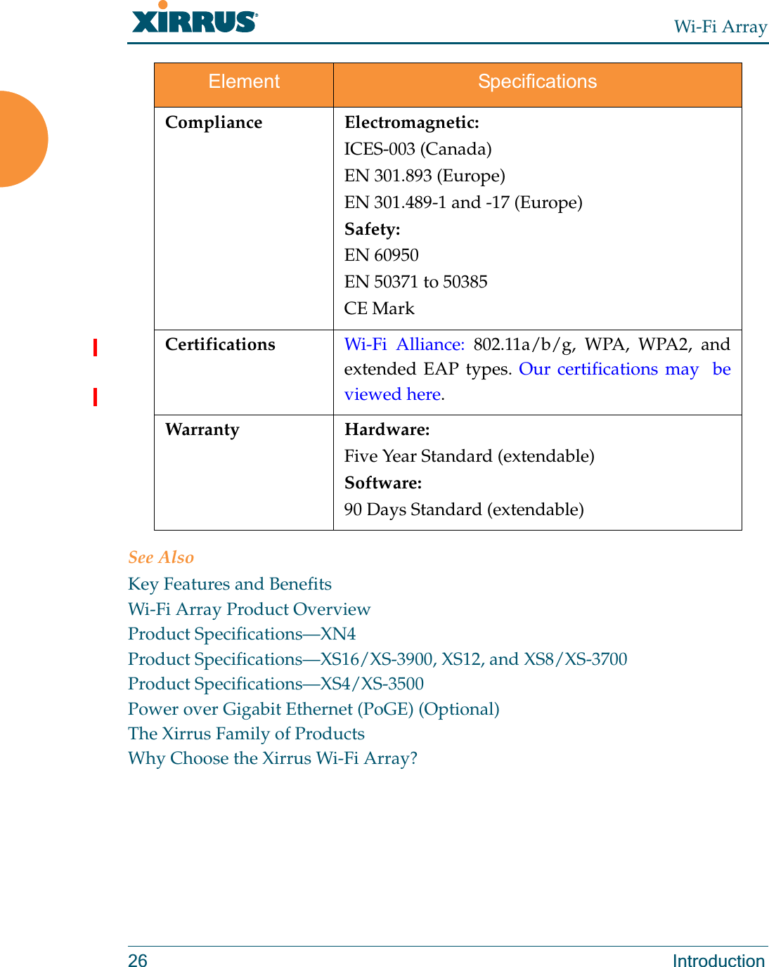
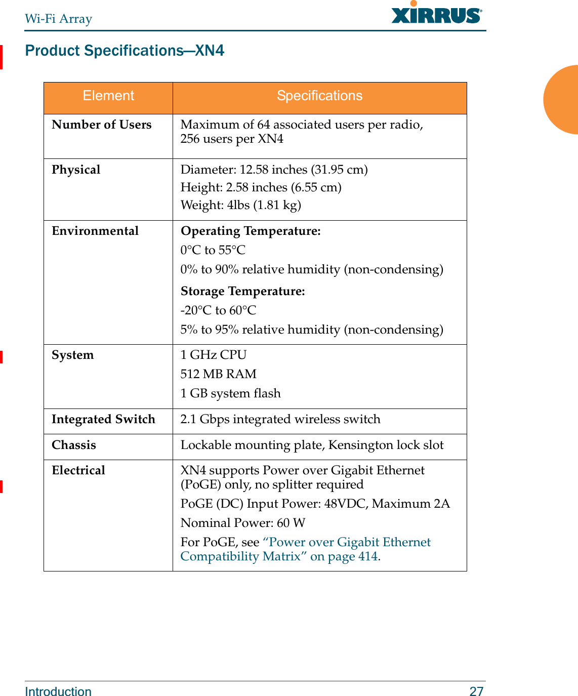
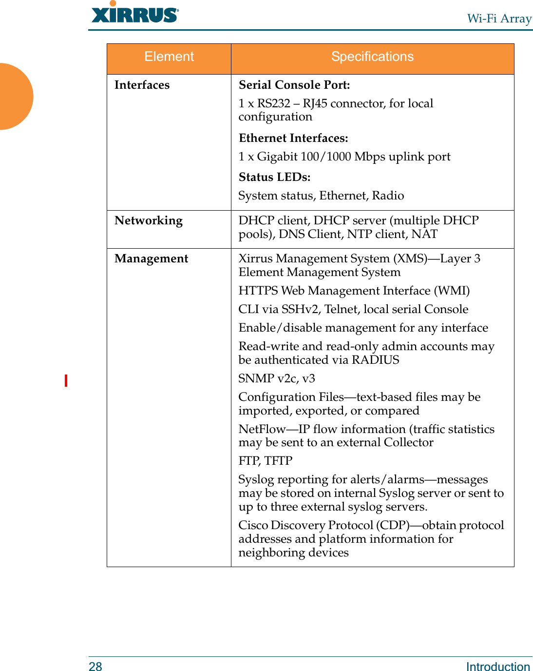
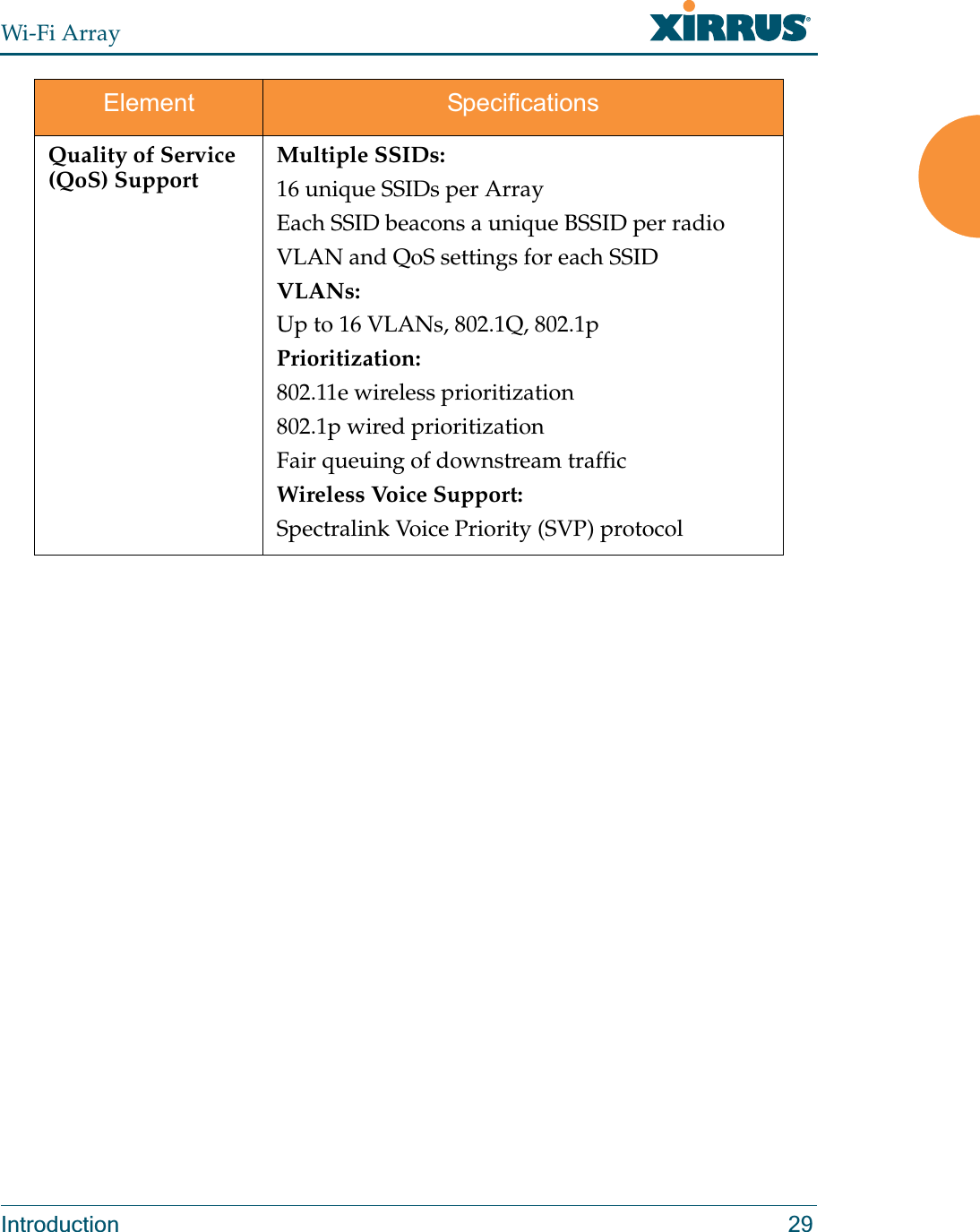
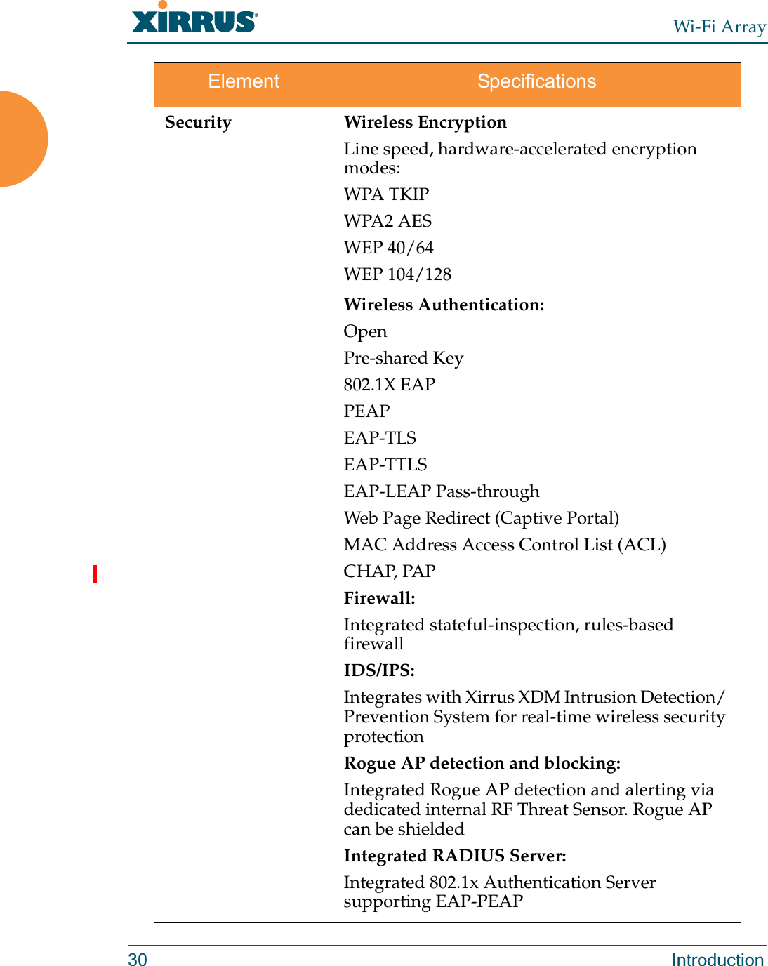
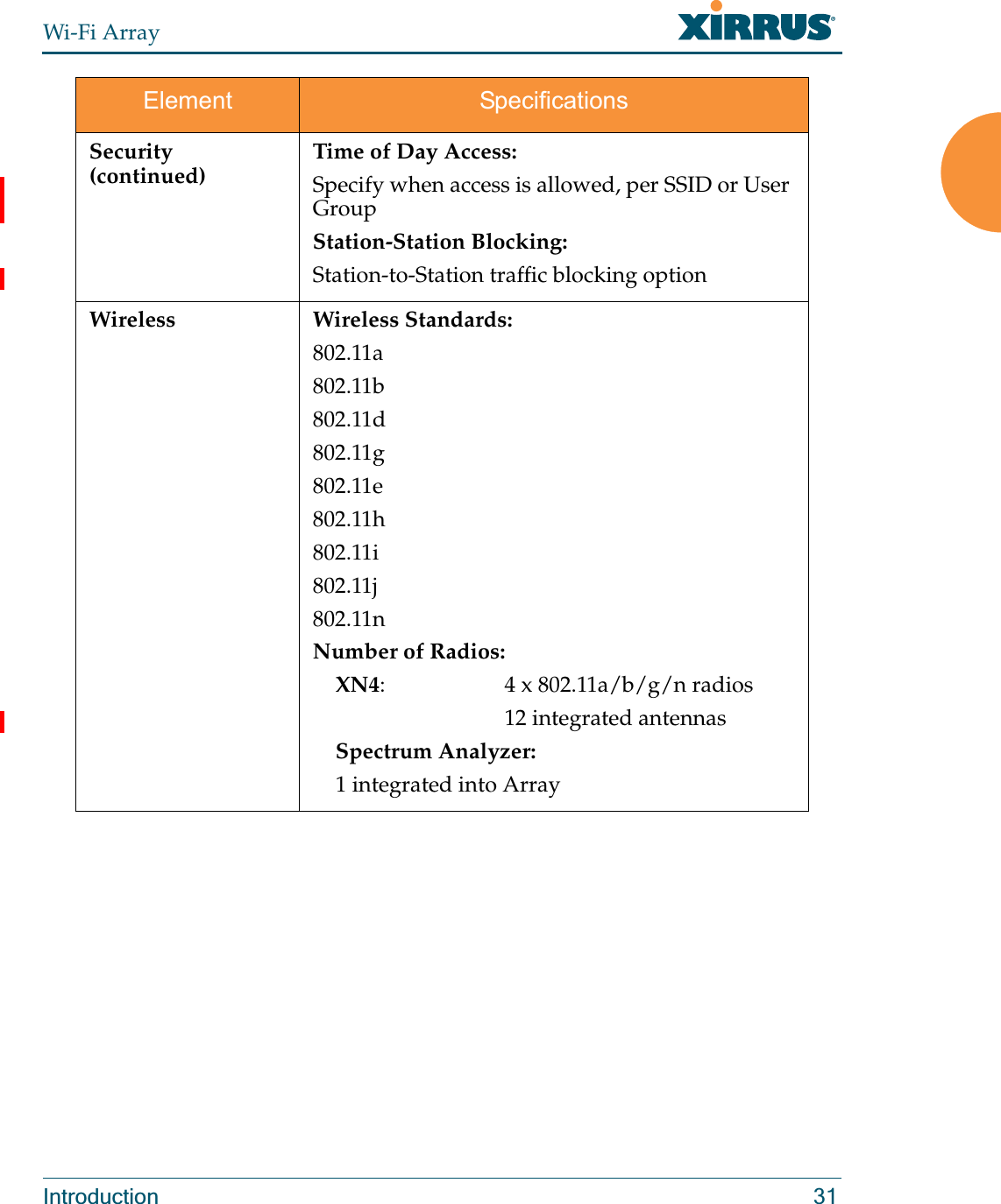
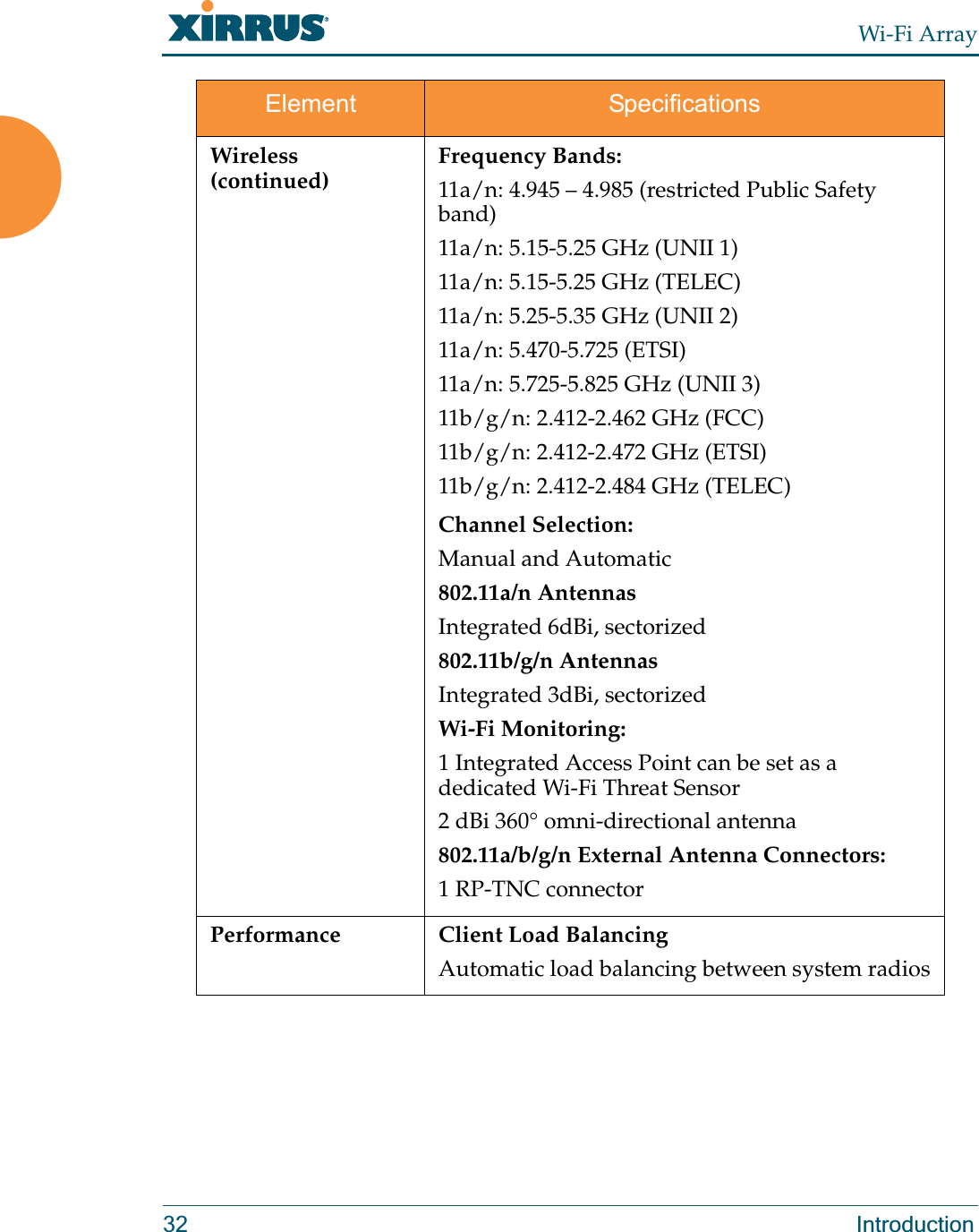
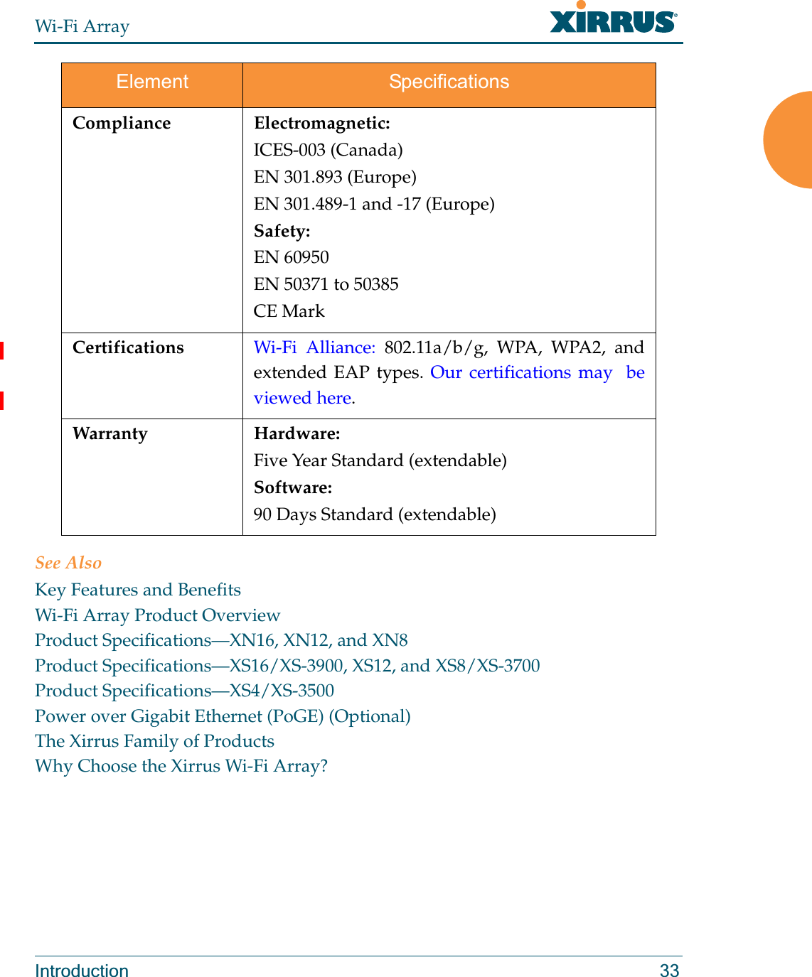
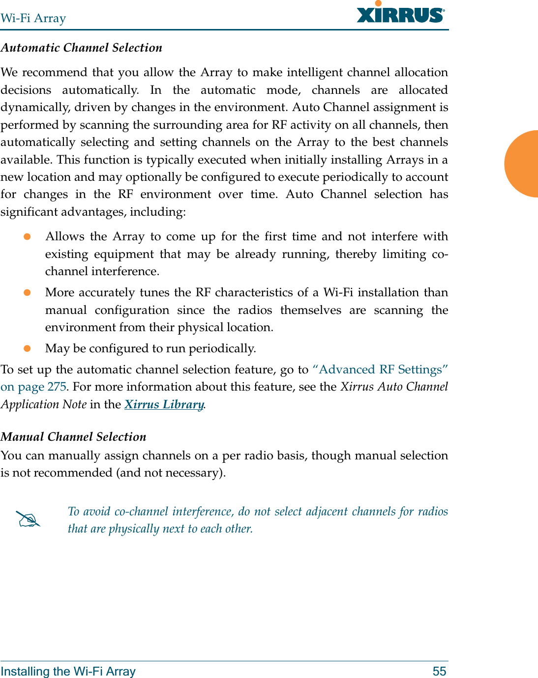
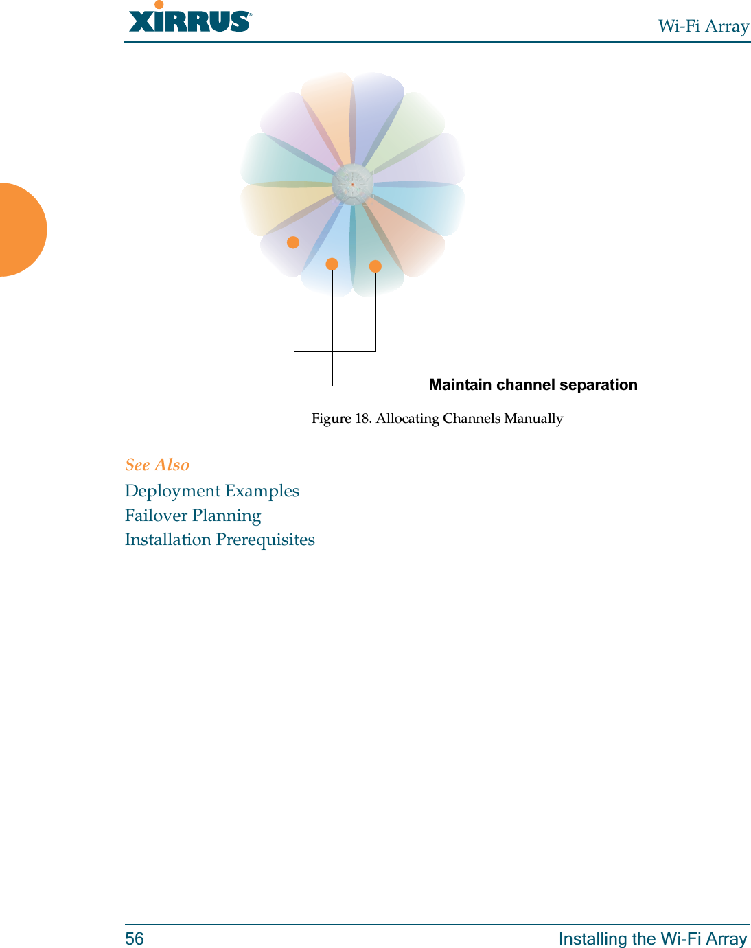
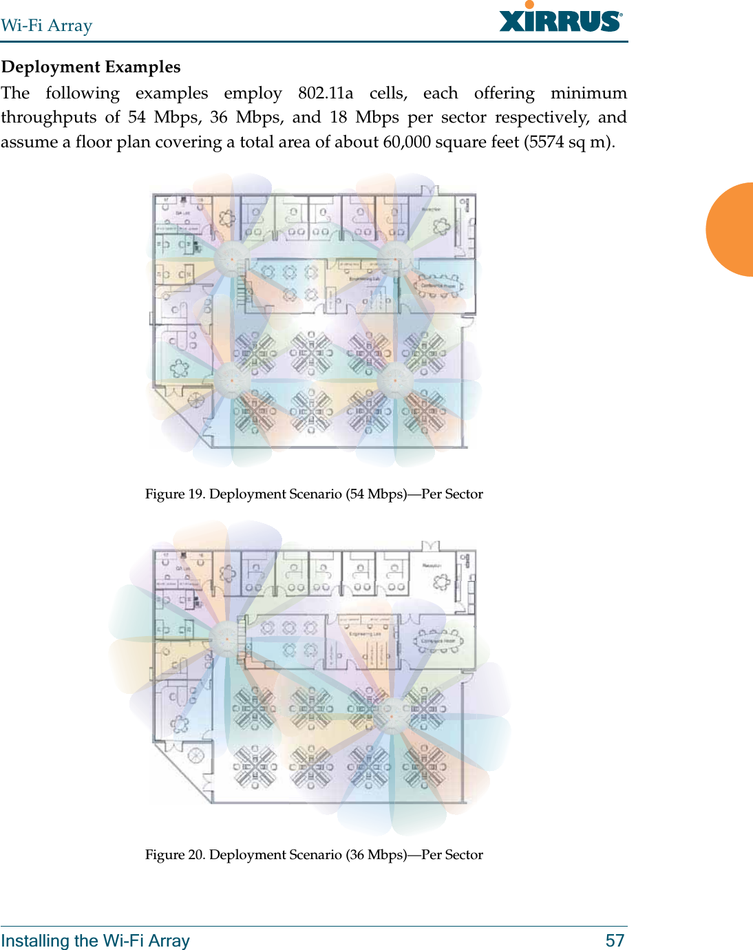
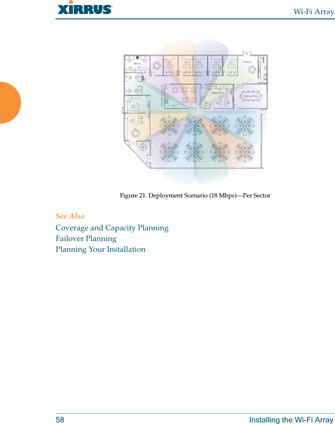
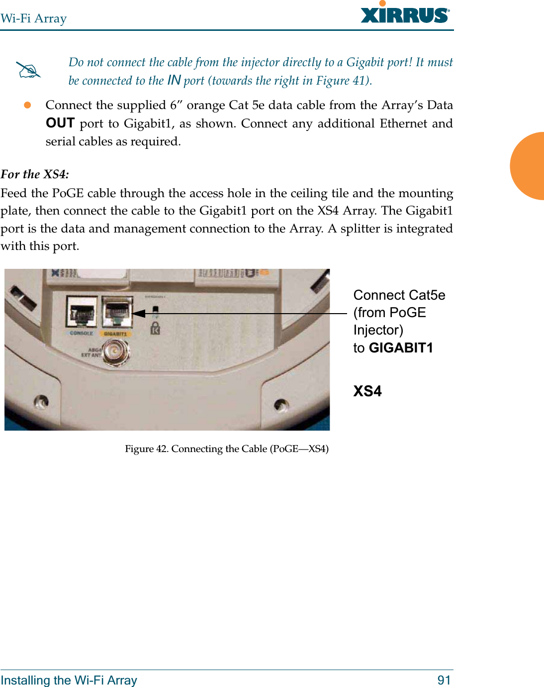
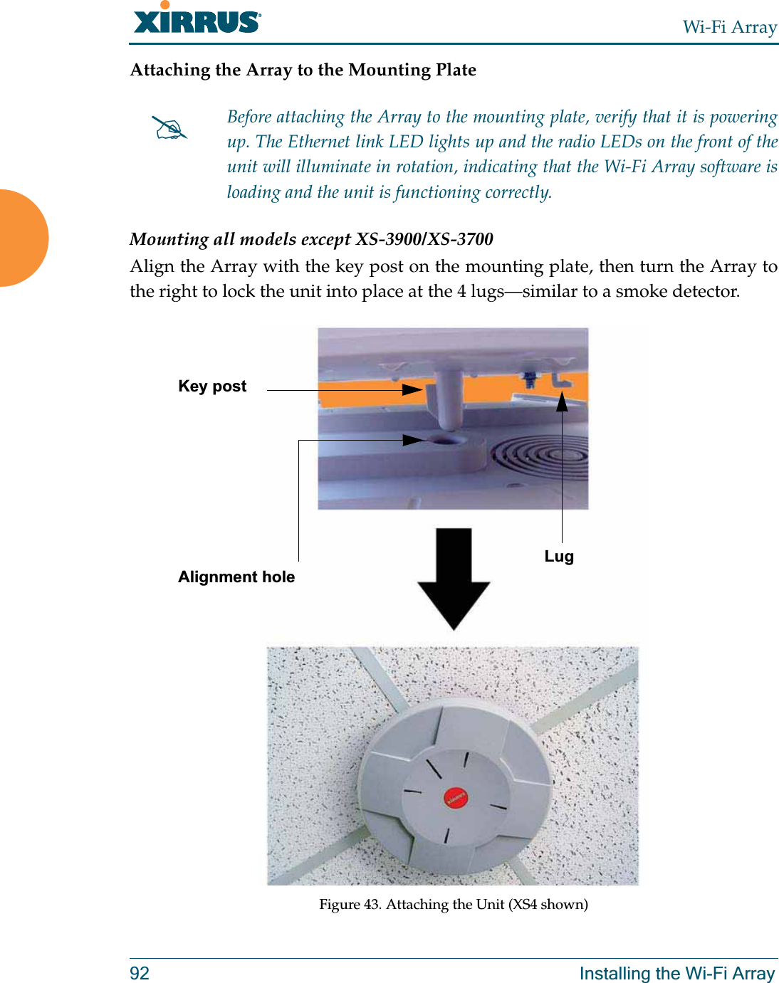
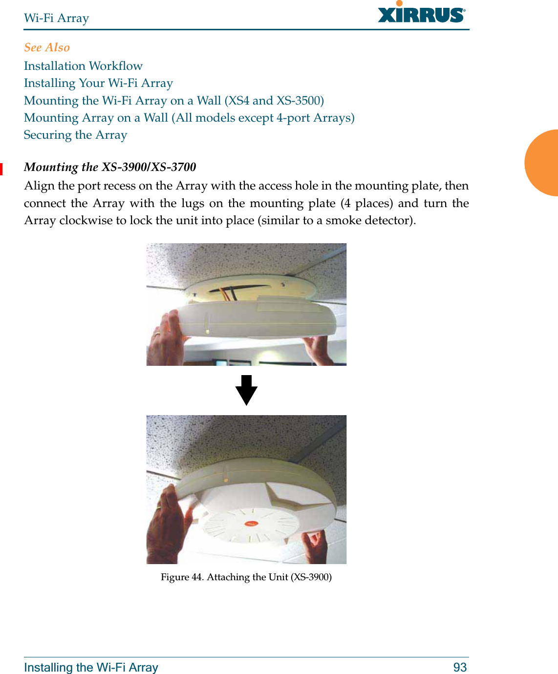
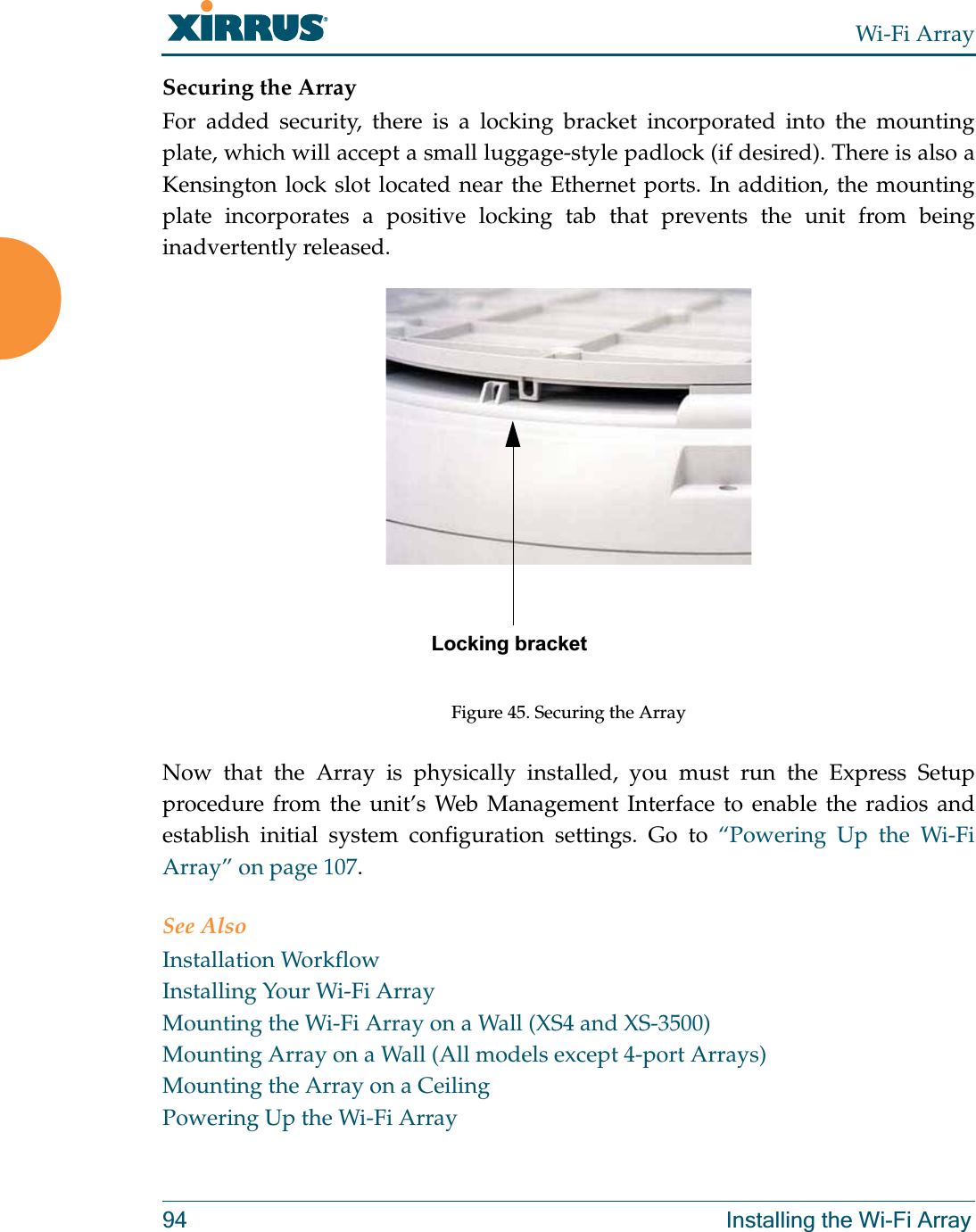
Cambium Networks XN4 Wireless LAN Array User Manual xirrus PDF
Xirrus, Inc. Wireless LAN Array xirrus PDF
UserManual.wiki
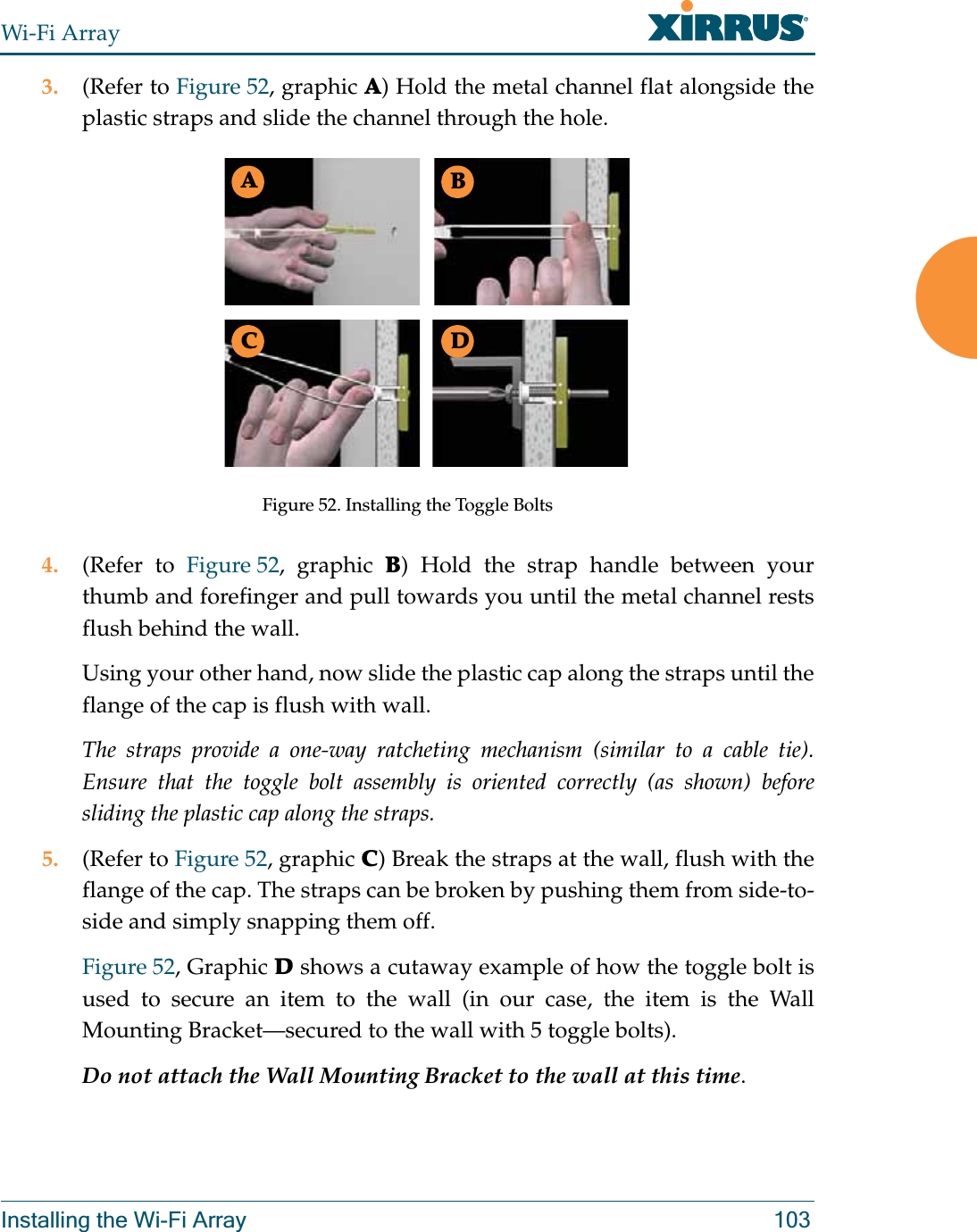
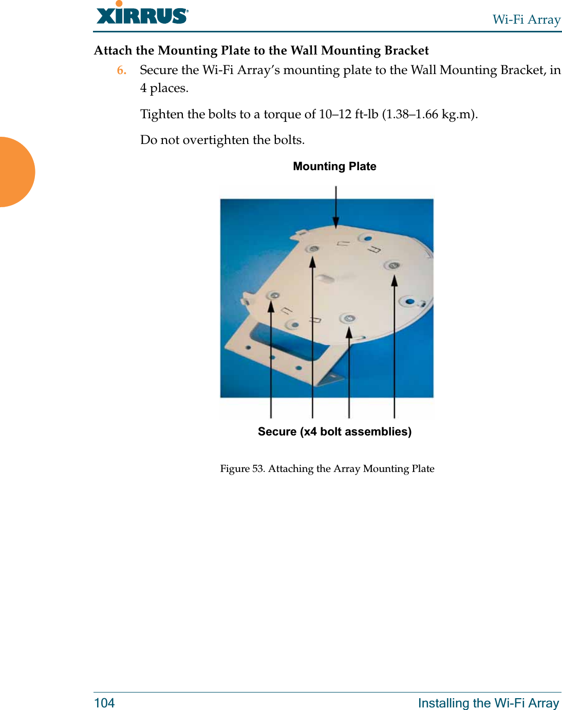
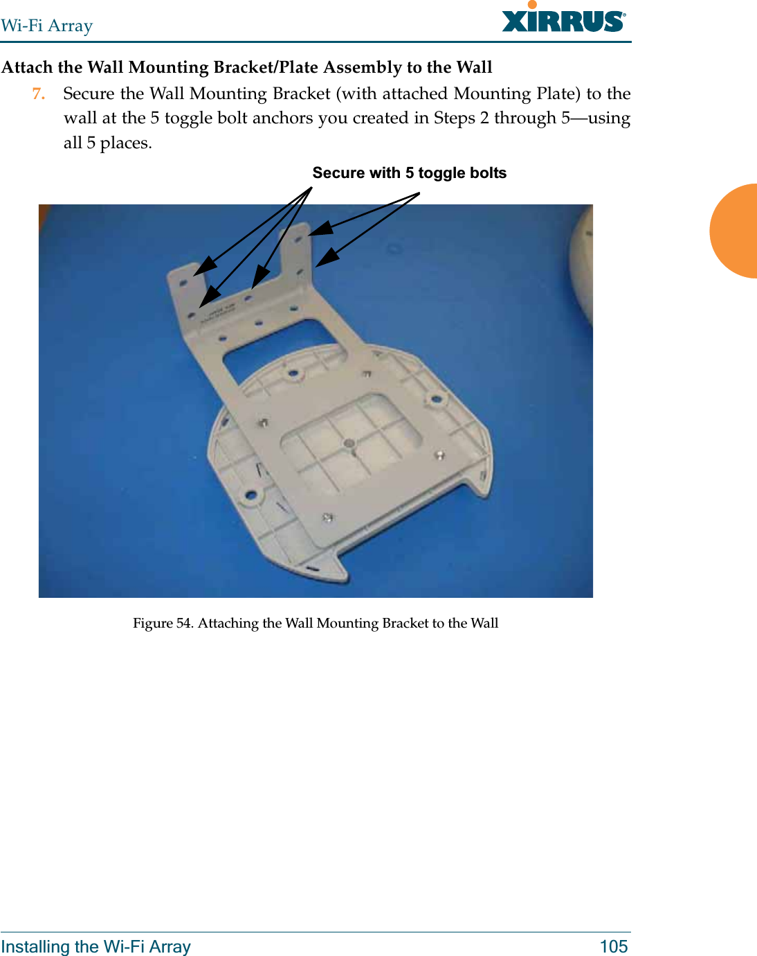
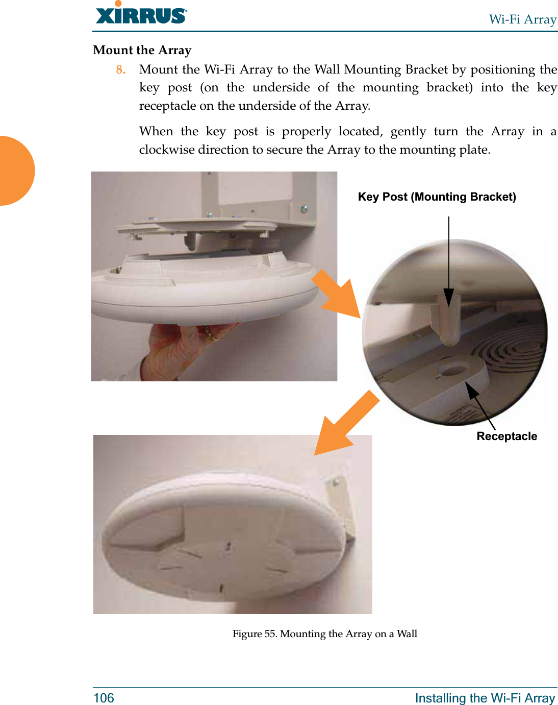
>
Cambium Networks
>
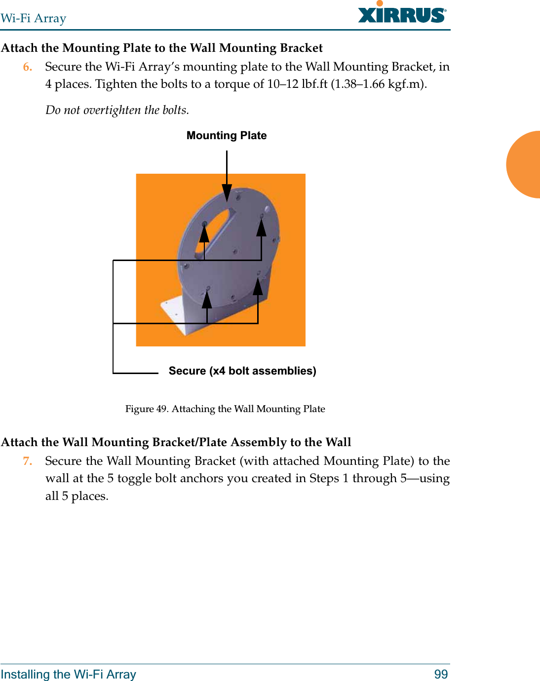
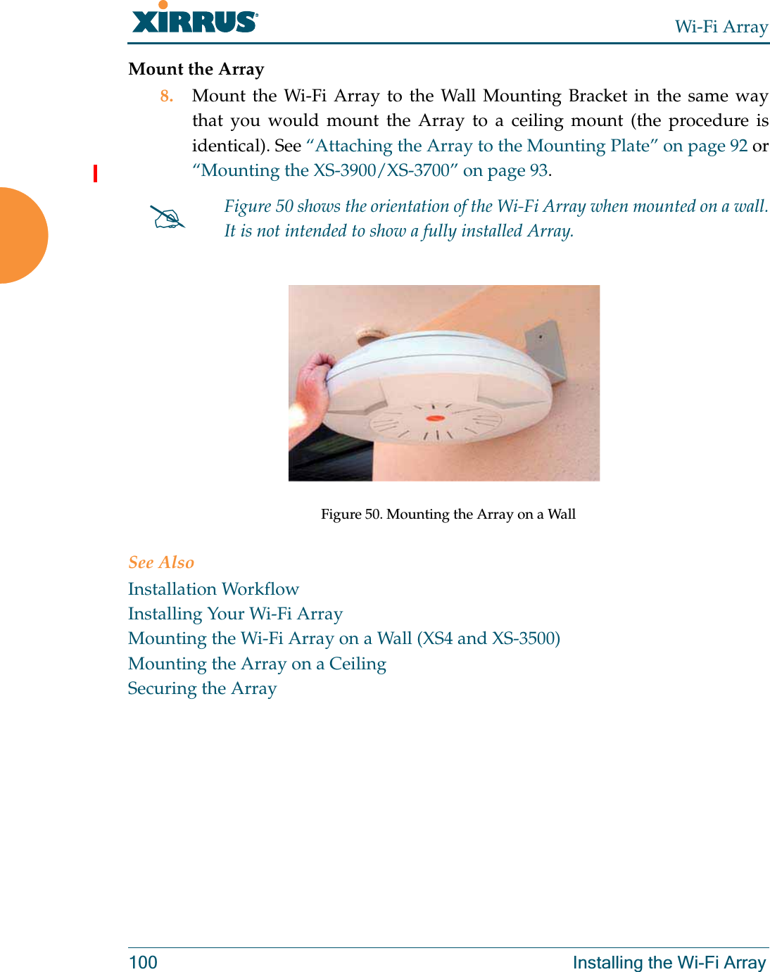
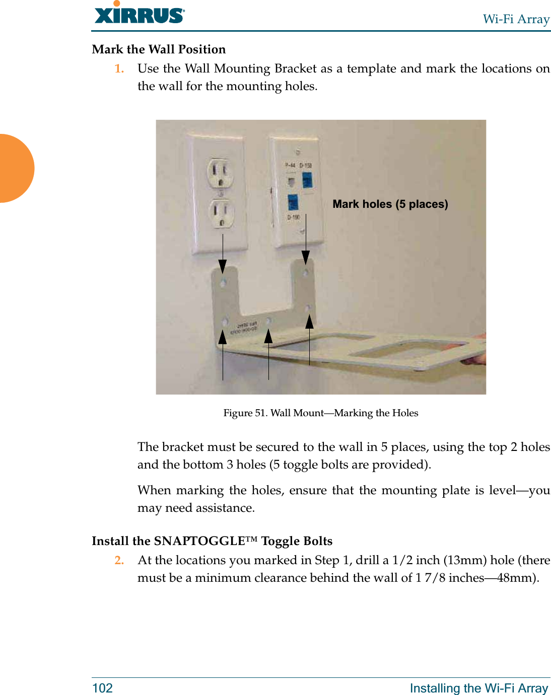
XN4 User Manual
>
User Manual 1
Contents
1.
User Manual 1
2.
User Manual 2
3.
User Manual 3
4.
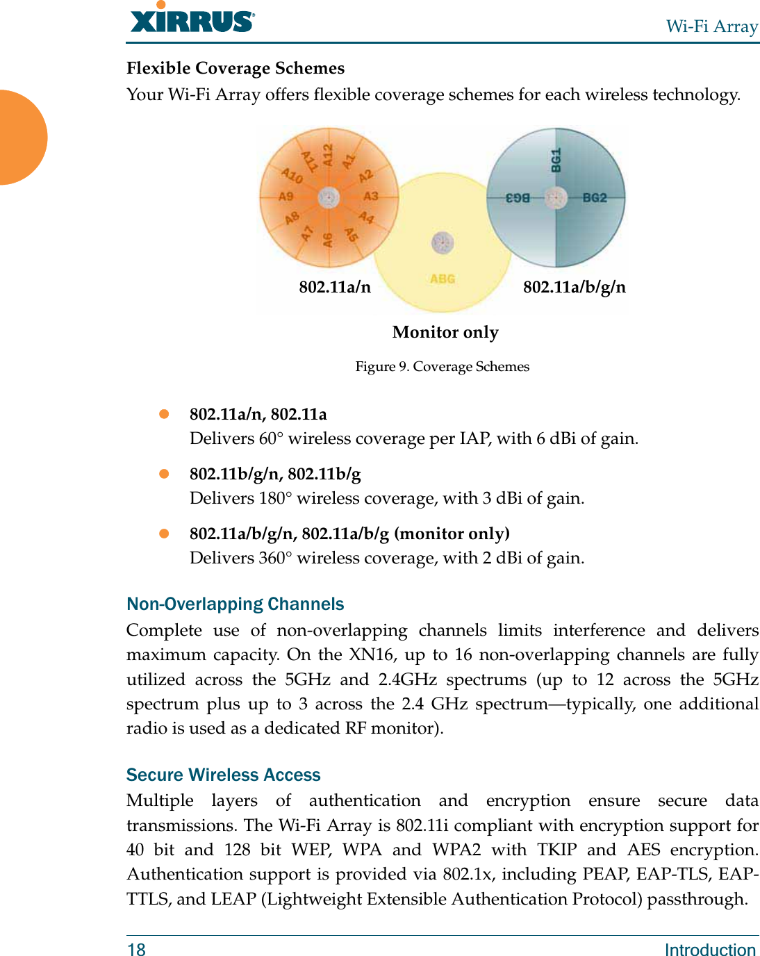
ArrayGuide_Rel4.0_RevW-part 1 of 2
5.
ArrayGuide_Rel4.0_RevW-part 2 of 2
User Manual 1
Navigation menu
Upload a User Manual
Namespaces
Wiki Guide
HTML
PDF
Info
Views
User Manual
Discussion / Help
Navigation