Cambium Networks XN4 Wireless LAN Array User Manual xirrus PDF
Xirrus, Inc. Wireless LAN Array xirrus PDF
Contents
User Manual 1
December 19, 2008
DRAFT3

All rights reserved. This document may not be reproduced or
disclosed in whole or in part by any means without the written
consent of Xirrus, Inc.
Part Number: 800-0006-001
(Revision T)
Wi-Fi Array
XN16, XN12, XN8, XN4
XS16, XS12, XS8, XS4
XS-3900, XS-3700, XS-3500
™

Trademarks
is a registered trademark of Xirrus, Inc. All other trademarks and brand
names are marks of their respective holders.
Please see Legal Notices, Warnings, Compliance Statements, and Warranty and
License Agreements in “Appendix F: Notices” on page 433.
Xirrus, Inc.
2101 Corporate Center Drive
Thousand Oaks, CA 91320
USA
Tel: 1.805.262.1600
1.800.947.7871 Toll Free in the US
Fax: 1.866.462.3980
www.xirrus.com

Wi-Fi Array
Table of Contents i
Table of Contents
List of Figures...................................................................................... xi
Introduction ......................................................................................... 1
The Xirrus Family of Products ............................................................................... 2
Nomenclature .................................................................................................... 4
About this User’s Guide .......................................................................................... 4
Organization ...................................................................................................... 4
Notes and Cautions .......................................................................................... 6
Screen Images .................................................................................................... 6
Your User’s Guide as a PDF Document ........................................................ 6
Hyperlinks ......................................................................................................... 7
Window or Page? .............................................................................................. 7
Why Choose the Xirrus Wi-Fi Array? ................................................................... 7
Wi-Fi Array Product Overview ............................................................................. 9
Enterprise Class Security ................................................................................. 9
Wi-Fi Array Product Family ......................................................................... 10
XN Family of Arrays ............................................................................... 10
XS Family of Arrays ................................................................................ 11
Deployment Flexibility .................................................................................. 12
Power over Gigabit Ethernet (PoGE) (Optional) ................................ 13
Enterprise Class Management ...................................................................... 14
Key Features and Benefits ..................................................................................... 16
High Capacity and High Performance ........................................................ 16
Extended Coverage ......................................................................................... 17
Flexible Coverage Schemes .................................................................... 18
Non-Overlapping Channels .......................................................................... 18
Secure Wireless Access .................................................................................. 18
Applications Enablement .............................................................................. 19
SDMA Optimization ...................................................................................... 19
Fast Roaming ................................................................................................... 19
Easy Deployment ............................................................................................ 19
Product Specifications—XN16, XN12, and XN8 ............................................... 20
Product Specifications—XN4 ............................................................................... 27

Wi-Fi Array
ii Table of Contents
Product Specifications—XS16/XS-3900, XS12, and
XS8/XS-3700 ........................................................................................................... 34
Product Specifications—XS4/XS-3500 ............................................................... 39
Installing the Wi-Fi Array ................................................................. 45
Installation Prerequisites ...................................................................................... 45
Optional Network Components ................................................................... 47
Client Requirements ....................................................................................... 47
Planning Your Installation .................................................................................... 48
General Deployment Considerations .......................................................... 48
Coverage and Capacity Planning ................................................................. 50
Placement .................................................................................................. 50
RF Patterns ................................................................................................ 51
Capacity and Cell Sizes ........................................................................... 52
Fine Tuning Cell Sizes ............................................................................. 53
Roaming Considerations ........................................................................ 54
Allocating Channels ................................................................................ 54
Deployment Examples ............................................................................ 57
IEEE 802.11n Deployment Considerations ................................................. 59
MIMO (Multiple-In Multiple-Out) ........................................................ 60
Multiple Data Streams—Spatial Multiplexing .................................... 62
Channel Bonding ..................................................................................... 63
Improved MAC Throughput ................................................................. 64
Short Guard Interval ............................................................................... 64
Obtaining Higher Data Rates ................................................................. 65
802.11n Capacity ...................................................................................... 66
Failover Planning ............................................................................................ 67
Port Failover Protection .......................................................................... 67
Switch Failover Protection ..................................................................... 68
Power Planning ............................................................................................... 69
AC Power .................................................................................................. 69
Power over Gigabit Ethernet ................................................................. 69
Security Planning ............................................................................................ 70
Wireless Encryption ................................................................................ 70
Authentication ......................................................................................... 70
Meeting PCI DSS Standards ................................................................... 71
Meeting FIPS Standards ......................................................................... 71

Wi-Fi Array
Table of Contents iii
Port Requirements .......................................................................................... 72
Network Management Planning .................................................................. 75
WDS Planning ................................................................................................. 76
Common Deployment Options .................................................................... 79
Installation Workflow ........................................................................................... 80
Unpacking the Wi-Fi Array .................................................................................. 81
Installing Your Wi-Fi Array .................................................................................. 83
Choosing a Location ....................................................................................... 83
Wiring Considerations ............................................................................ 84
Mounting the Array on a Ceiling ................................................................. 86
Attaching the T-Bar Clips to the Template .......................................... 86
Secure the T-Bar Clips to the Ceiling Support Grid ........................... 87
Installing the Mounting Plate ................................................................ 88
Connecting the Cables—AC Option ..................................................... 89
Connecting the Cables—PoGE Option ................................................. 90
Attaching the Array to the Mounting Plate ......................................... 92
Securing the Array ................................................................................... 94
Dismounting the Array ........................................................................... 95
Mounting Array on a Wall (All models except 4-port Arrays) ................ 96
Kit Contents (Wall Mount Assembly) .................................................. 96
Tools Required ......................................................................................... 96
Mark the Wall Position ........................................................................... 97
Install the SNAPTOGGLE™ Toggle Bolts ........................................... 98
Attach the Mounting Plate to the Wall Mounting Bracket ................ 99
Attach the Wall Mounting Bracket/Plate Assembly to the Wall ..... 99
Mount the Array .................................................................................... 100
Mounting the Wi-Fi Array on a Wall (XS4 and XS-3500) ....................... 101
Kit Contents (Wall Mount Assembly) ................................................ 101
Tools Required ....................................................................................... 101
Mark the Wall Position ......................................................................... 102
Install the SNAPTOGGLE™ Toggle Bolts ......................................... 102
Attach the Mounting Plate to the Wall Mounting Bracket .............. 104
Attach the Wall Mounting Bracket/Plate Assembly to the Wall ... 105
Mount the Array .................................................................................... 106
Removing the Array .............................................................................. 107
Powering Up the Wi-Fi Array ............................................................................ 107
Array LED Operating Sequences ............................................................... 108

Wi-Fi Array
iv Table of Contents
LED Boot Sequence ............................................................................... 108
LED Operation when Array is Running ............................................ 109
Establishing Communication with the Array .................................................. 110
Using the Serial Port ..................................................................................... 110
Using the Ethernet Ports .............................................................................. 110
Logging In ...................................................................................................... 111
Performing the Express Setup Procedure ......................................................... 112
Procedure for Performing an Express Setup ............................................ 113
The Web Management Interface ................................................ 119
An Overview ........................................................................................................ 120
Structure of the WMI ........................................................................................... 121
User Interface ....................................................................................................... 123
Utility Buttons ........................................................................................ 124
Logging In ............................................................................................................. 126
Applying Configuration Changes ..................................................................... 126
Viewing Status on the Wi-Fi Array............................................... 127
Array Status Windows ........................................................................................ 127
Array Summary ............................................................................................ 128
Content of the Array Summary Window .......................................... 128
Array Information ........................................................................................ 131
Array Configuration ..................................................................................... 132
Admin History .............................................................................................. 133
Network Status Windows ................................................................................... 133
Network Map ................................................................................................ 134
Content of the Network Map Window .............................................. 134
Spanning Tree Status .................................................................................... 136
Routing Table ................................................................................................ 138
ARP Table ...................................................................................................... 138
DHCP Leases ................................................................................................. 139
Connection Tracking/NAT ......................................................................... 140
CDP Neighbors ............................................................................................. 141
RF Monitor Windows .......................................................................................... 142
IAPs ................................................................................................................. 143
Spectrum Analyzer ...................................................................................... 144
Intrusion Detection ...................................................................................... 148

Wi-Fi Array
Table of Contents v
Station Status Windows ...................................................................................... 150
Stations ........................................................................................................... 151
Location Map ................................................................................................. 152
RSSI ................................................................................................................. 158
Signal-to-Noise Ratio (SNR) ........................................................................ 160
Noise Floor ..................................................................................................... 162
Max by IAP .................................................................................................... 164
Statistics Windows ............................................................................................... 165
IAP Statistics Summary ................................................................................ 165
Per-IAP Statistics ........................................................................................... 166
Network Statistics ......................................................................................... 168
VLAN Statistics ............................................................................................. 169
WDS Statistics ................................................................................................ 170
Filter Statistics ............................................................................................... 171
Station Statistics ............................................................................................ 171
Per-Station Statistics ..................................................................................... 172
System Log Window ........................................................................................... 173
Configuring the Wi-Fi Array .......................................................... 175
Express Setup ........................................................................................................ 176
Network ................................................................................................................. 182
Network Interfaces ...................................................................................... 183
Network Interface Ports ........................................................................ 184
DNS Settings .................................................................................................. 190
CDP Settings .................................................................................................. 191
Services .................................................................................................................. 193
Time Settings (NTP) ..................................................................................... 194
NetFlow .......................................................................................................... 196
System Log ..................................................................................................... 197
SNMP .............................................................................................................. 200
DHCP Server ................................................................................................. 203
VLANs ................................................................................................................... 205
Understanding Virtual Tunnels .......................................................... 205
VLAN Management ..................................................................................... 207
Security .................................................................................................................. 209
Understanding Security ........................................................................ 210
Certificates and Connecting Securely to the WMI ............................ 213

Wi-Fi Array
vi Table of Contents
Using the Array’s Default Certificate ................................................. 213
Using an External Certificate Authority ............................................. 214
Admin Management .................................................................................... 215
Admin RADIUS ............................................................................................ 216
Management Control ................................................................................... 219
Access Control List ....................................................................................... 223
Global Settings .............................................................................................. 225
External Radius ............................................................................................. 228
Internal Radius .............................................................................................. 231
Rogue Control List ........................................................................................ 233
SSIDs ...................................................................................................................... 235
Understanding SSIDs ............................................................................ 236
Understanding QoS Priority on the Wi-Fi Array .............................. 237
SSID Management ........................................................................................ 240
SSID List (top of page) .......................................................................... 240
SSID Limits ............................................................................................. 243
Web Page Redirect Configuration Settings ........................................ 244
Groups ................................................................................................................... 247
Understanding Groups ......................................................................... 247
Using Groups ......................................................................................... 248
Group Management ..................................................................................... 249
Group Limits .......................................................................................... 251
IAPs ........................................................................................................................ 253
Understanding Fast Roaming .............................................................. 254
IAP Settings ................................................................................................... 255
Global Settings (IAP) ................................................................................... 260
Beacon Configuration ........................................................................... 262
Station Management ............................................................................. 262
Advanced Traffic Optimization .......................................................... 263
Global Settings .11a ...................................................................................... 267
Global Settings .11bg .................................................................................... 269
Global Settings .11n ...................................................................................... 273
Advanced RF Settings .................................................................................. 275
About Standby Mode ............................................................................ 275
About Blocking Rogue APs .................................................................. 276
RF Intrusion Detection .......................................................................... 277
RF Resilience .......................................................................................... 278

Wi-Fi Array
Table of Contents vii
RF Power & Sensitivity ......................................................................... 279
RF Spectrum Management ................................................................... 280
LED Settings .................................................................................................. 283
WDS ....................................................................................................................... 285
About Configuring WDS Links ........................................................... 285
WDS Client Links .......................................................................................... 287
Filters ..................................................................................................................... 289
Filter Lists ...................................................................................................... 290
Filter Management ....................................................................................... 291
Using Tools on the Wi-Fi Array..................................................... 295
System Tools ......................................................................................................... 296
System ..................................................................................................... 297
Configuration ......................................................................................... 298
Diagnostics ............................................................................................. 299
Web Page Redirect ................................................................................. 300
Tools ........................................................................................................ 301
Progress and Status Frames ................................................................. 303
CLI ......................................................................................................................... 303
Logout .................................................................................................................... 305
The Command Line Interface...................................................... 307
Establishing a Secure Shell (SSH) Connection ................................................. 308
Getting Started with the CLI .............................................................................. 309
Inputting Commands ................................................................................... 309
Getting Help .................................................................................................. 309
Top Level Commands ......................................................................................... 311
Root Command Prompt ............................................................................... 311
configure Commands ................................................................................... 312
show Commands .......................................................................................... 315
statistics Commands ..................................................................................... 318
Configuration Commands .................................................................................. 320
acl .................................................................................................................... 320
admin .............................................................................................................. 321
cdp ................................................................................................................... 322
clear ................................................................................................................. 323
contact-info .................................................................................................... 324

Wi-Fi Array
viii Table of Contents
date-time ........................................................................................................ 325
dhcp-server .................................................................................................... 326
dns ................................................................................................................... 327
file .................................................................................................................... 328
filter ................................................................................................................. 331
fips ................................................................................................................... 333
group .............................................................................................................. 334
hostname ........................................................................................................ 334
https ................................................................................................................ 335
interface .......................................................................................................... 336
license ............................................................................................................. 337
load ................................................................................................................. 337
location ........................................................................................................... 338
management .................................................................................................. 338
more ................................................................................................................ 338
netflow ............................................................................................................ 339
no ..................................................................................................................... 340
pci-audit ......................................................................................................... 342
quit .................................................................................................................. 343
radius-server .................................................................................................. 343
reboot .............................................................................................................. 344
reset ................................................................................................................. 344
run-tests .......................................................................................................... 345
security ........................................................................................................... 347
snmp ............................................................................................................... 348
ssh .................................................................................................................... 348
ssid .................................................................................................................. 350
standby ........................................................................................................... 350
syslog .............................................................................................................. 351
telnet ............................................................................................................... 353
uptime ............................................................................................................. 353
vlan .................................................................................................................. 354
Sample Configuration Tasks .............................................................................. 355
Configuring a Simple Open Global SSID .................................................. 356
Configuring a Global SSID using WPA-PEAP ......................................... 357
Configuring an SSID-Specific SSID using WPA-PEAP ........................... 358
Enabling Global IAPs ................................................................................... 359

Wi-Fi Array
Table of Contents ix
Disabling Global IAPs .................................................................................. 360
Enabling a Specific IAP ................................................................................ 361
Disabling a Specific IAP ............................................................................... 362
Setting Cell Size Auto-Configuration for All IAPs .................................. 363
Setting the Cell Size for All IAPs ................................................................ 364
Setting the Cell Size for a Specific IAP ....................................................... 365
Configuring VLANs on an Open SSID ...................................................... 366
Configuring Radio Assurance Mode (Loopback Tests) .......................... 367
Appendices..................................................................................... 369
Appendix A: Servicing the Wi-Fi Array ............................................................. 371
Removing the Access Panel ................................................................................ 373
Reinstalling the Access Panel ............................................................................. 376
Replacing the FLASH Memory Module ........................................................... 378
Replacing the Main System Memory ................................................................ 380
Replacing the Integrated Access Point Radio Module ................................... 382
Replacing the Power Supply Module ............................................................... 385
Appendix B: Quick Reference Guide ............................................................... 387
Factory Default Settings ...................................................................................... 387
Host Name ..................................................................................................... 387
Network Interfaces ....................................................................................... 387
Serial ........................................................................................................ 387
Gigabit 1 and Gigabit 2 ......................................................................... 388
Fast Ethernet ........................................................................................... 388
Integrated Access Points (IAPs) .................................................................. 389
Server Settings ............................................................................................... 390
NTP .......................................................................................................... 390
Syslog ...................................................................................................... 390
SNMP ...................................................................................................... 390
DHCP .............................................................................................................. 391
Default SSID .................................................................................................. 391
Security .......................................................................................................... 392
Global Settings - Encryption ............................................................... 392
External RADIUS (Global) .................................................................. 392
Internal RADIUS .................................................................................... 393
Administrator Account and Password ...................................................... 394

Wi-Fi Array
x Table of Contents
Management .................................................................................................. 394
Keyboard Shortcuts ............................................................................................. 394
Appendix C: Technical Support ........................................................................ 397
General Hints and Tips ....................................................................................... 397
Frequently Asked Questions .............................................................................. 398
Multiple SSIDs ............................................................................................... 398
Security ........................................................................................................... 400
VLAN Support .............................................................................................. 403
Array Monitor and Radio Assurance Capabilities .......................................... 406
Enabling Monitoring on the Array ..................................................... 406
How Monitoring Works ............................................................................... 406
Radio Assurance ........................................................................................... 407
Radio Assurance Options ..................................................................... 408
Upgrading the Array via CLI ............................................................................. 409
Sample Output for the Upgrade Procedure: ............................................. 410
Power over Gigabit Ethernet Compatibility Matrix ....................................... 414
Determining If an XS-3700 or XS-3900 is Modified for PoGE ......... 416
Contact Information ............................................................................................ 417
Appendix D: Implementing PCI DSS ............................................................... 419
Payment Card Industry Data Security Standard Overview .......................... 419
PCI DSS and Wireless .......................................................................................... 420
The Xirrus Array PCI Compliance Configuration .......................................... 421
The pci-audit Command ..................................................................................... 422
Additional Resources .......................................................................................... 423
Appendix E: Implementing FIPS Security ....................................................... 425
Appendix F: Notices ........................................................................................... 433
Notices ................................................................................................................... 433
EU Directive 1999/5/EC Compliance Information ........................................ 436
Safety Warnings ................................................................................................... 443
Translated Safety Warnings ............................................................................... 444
Software Warranty and License Agreement .................................................... 445
Hardware Warranty Agreement ....................................................................... 452
Glossary of Terms.......................................................................... 455
Index................................................................................................ 467

Wi-Fi Array
List of Figures xi
List of Figures
Figure 1. Xirrus Arrays............................................................................................... 2
Figure 2. The Xirrus Management System .............................................................. 3
Figure 3. Wi-Fi Array (XN16).................................................................................... 9
Figure 4. Wireless Coverage Patterns .................................................................... 12
Figure 5. XP8 - Power over Ethernet Usage .......................................................... 13
Figure 6. WMI: Array Status.................................................................................... 14
Figure 7. Layout of IAPs (XN16)............................................................................. 16
Figure 8. Naming of IAPs (XS16)............................................................................ 17
Figure 9. Coverage Schemes.................................................................................... 18
Figure 10. Wall Thickness Considerations .............................................................. 49
Figure 11. Unit Placement.......................................................................................... 50
Figure 12. Full (Normal) Coverage........................................................................... 51
Figure 13. Adjusting RF Patterns.............................................................................. 51
Figure 14. Custom Coverage ..................................................................................... 52
Figure 15. Connection Rate vs. Distance.................................................................. 52
Figure 16. Transmit Power......................................................................................... 53
Figure 17. Overlapping Cells..................................................................................... 54
Figure 18. Allocating Channels Manually............................................................... 56
Figure 19. Deployment Scenario (54 Mbps)—Per Sector ...................................... 57
Figure 20. Deployment Scenario (36 Mbps)—Per Sector ...................................... 57
Figure 21. Deployment Scenario (18 Mbps)—Per Sector ...................................... 58
Figure 22. Classic 802.11 Signal Transmission........................................................ 60
Figure 23. MIMO Signal Processing......................................................................... 61
Figure 24. Spatial Multiplexing................................................................................. 62
Figure 25. Channel Bonding...................................................................................... 63
Figure 26. MAC Throughput Improvements.......................................................... 64
Figure 27. Computing 802.11n Data Rates .............................................................. 65
Figure 28. 802.11n Increases Capacity...................................................................... 66
Figure 29. Port Failover Protection........................................................................... 67
Figure 30. Switch Failover Protection ...................................................................... 68
Figure 31. Port Requirements for XMS .................................................................... 72
Figure 32. WDS Link................................................................................................... 76
Figure 33. A Multiple Hop WDS Connection ......................................................... 77
Figure 34. WDS Failover Protection ......................................................................... 77

Wi-Fi Array
xii List of Figures
Figure 35. Installation Workflow .............................................................................. 80
Figure 36. Array Placement ....................................................................................... 83
Figure 37. Attaching the T-Bar Clips to the Template ........................................... 86
Figure 38. Attaching the T-Bar Clips to the Ceiling Grid...................................... 87
Figure 39. Installing the Mounting Plate ................................................................. 88
Figure 40. Connecting the Cables ............................................................................. 89
Figure 41. Connecting the Cables (PoGE—XS8/XS12/XS16) .............................. 90
Figure 42. Connecting the Cable (PoGE—XS4) ...................................................... 91
Figure 43. Attaching the Unit (XS4 shown)............................................................. 92
Figure 44. Attaching the Unit (XS-3900) .................................................................. 93
Figure 45. Securing the Array.................................................................................... 94
Figure 46. IAP Positions (XS16 shown).................................................................... 95
Figure 47. Wall Mount—Marking the Holes........................................................... 97
Figure 48. Installing the Toggle Bolts....................................................................... 98
Figure 49. Attaching the Wall Mounting Plate ....................................................... 99
Figure 50. Mounting the Array on a Wall ............................................................. 100
Figure 51. Wall Mount—Marking the Holes......................................................... 102
Figure 52. Installing the Toggle Bolts..................................................................... 103
Figure 53. Attaching the Array Mounting Plate................................................... 104
Figure 54. Attaching the Wall Mounting Bracket to the Wall ............................ 105
Figure 55. Mounting the Array on a Wall ............................................................. 106
Figure 56. LED Locations (XS-3900) ....................................................................... 107
Figure 57. Network Interface Ports......................................................................... 110
Figure 58. Express Setup.......................................................................................... 112
Figure 59. LEDs are Switched On........................................................................... 117
Figure 60. Web Management Interface.................................................................. 120
Figure 61. WMI: Frames........................................................................................... 123
Figure 62. WMI: Utility Buttons.............................................................................. 124
Figure 63. Feedback Form........................................................................................ 125
Figure 64. Logging In to the Wi-Fi Array .............................................................. 126
Figure 65. Array Summary ...................................................................................... 128
Figure 66. Disabled IAP (Partial View).................................................................. 129
Figure 67. IAP Cells .................................................................................................. 130
Figure 68. Array Information .................................................................................. 131
Figure 69. Show Configuration ............................................................................... 132
Figure 70. Admin Login History............................................................................. 133
Figure 71. Network Map.......................................................................................... 134

Wi-Fi Array
List of Figures xiii
Figure 72. Spanning Tree Status.............................................................................. 137
Figure 73. Routing Table.......................................................................................... 138
Figure 74. ARP Table ................................................................................................ 138
Figure 75. DHCP Leases........................................................................................... 139
Figure 76. Connection Tracking.............................................................................. 140
Figure 77. CDP Neighbors....................................................................................... 141
Figure 78. RF Monitor—IAPs.................................................................................. 143
Figure 79. RF Spectrum Analyzer........................................................................... 145
Figure 80. Intrusion Detection/Rogue AP List..................................................... 148
Figure 81. Stations..................................................................................................... 151
Figure 82. Location Map........................................................................................... 153
Figure 83. Controls for Location Map.................................................................... 154
Figure 84. Minimizing stations................................................................................ 155
Figure 85. Setting Array location on a Custom Image......................................... 157
Figure 86. Station RSSI Values ................................................................................ 158
Figure 87. Station RSSI Values—Colorized Graphical View .............................. 159
Figure 88. Station Signal-to-Noise Ratio Values................................................... 160
Figure 89. Station SNR Values—Colorized Graphical View .............................. 161
Figure 90. Station Noise Floor Values.................................................................... 162
Figure 91. Station Noise Floor Values—Colorized Graphical View.................. 163
Figure 92. Max by IAP.............................................................................................. 164
Figure 93. IAP Statistics Summary Page................................................................ 166
Figure 94. Individual IAP Statistics Page (for IAP abg(n)1) ............................... 167
Figure 95. Network Statistics................................................................................... 168
Figure 96. VLAN Statistics....................................................................................... 169
Figure 97. WDS Statistics ......................................................................................... 170
Figure 98. Filter Statistics ......................................................................................... 171
Figure 99. Station Statistics ...................................................................................... 171
Figure 100. Individual Station Statistics Page......................................................... 172
Figure 101. System Log ............................................................................................. 173
Figure 102. WMI: Express Setup............................................................................... 176
Figure 103. LEDs are Switched On........................................................................... 181
Figure 104. Network Interfaces................................................................................. 182
Figure 105. Network Settings .................................................................................... 183
Figure 106. Network Interface Ports......................................................................... 184
Figure 107. Port Modes (a-b) ..................................................................................... 186
Figure 108. Port Modes (c-d) ..................................................................................... 187

Wi-Fi Array
xiv List of Figures
Figure 109. Port Modes (e-f) ...................................................................................... 188
Figure 110. DNS Settings............................................................................................ 190
Figure 111. CDP Settings............................................................................................ 191
Figure 112. Services..................................................................................................... 193
Figure 113. Time Settings (Manual Time)................................................................ 194
Figure 114. Time Settings (NTP Time Enabled)...................................................... 195
Figure 115. NetFlow.................................................................................................... 196
Figure 116. System Log .............................................................................................. 197
Figure 117. SNMP ....................................................................................................... 200
Figure 118. DHCP Management............................................................................... 203
Figure 119. VLANs...................................................................................................... 205
Figure 120. VLAN Management............................................................................... 207
Figure 121. Security..................................................................................................... 209
Figure 122. Import Xirrus Certificate Authority..................................................... 214
Figure 123. Admin Management .............................................................................. 215
Figure 124. Admin RADIUS...................................................................................... 217
Figure 125. Management Control ............................................................................. 219
Figure 126. Access Control List................................................................................. 223
Figure 127. Global Settings (Security) ...................................................................... 225
Figure 128. External RADIUS Server ....................................................................... 228
Figure 129. Internal RADIUS Server ........................................................................ 231
Figure 130. Rogue Control List ................................................................................. 233
Figure 131. SSIDs......................................................................................................... 235
Figure 132. Four Traffic Classes................................................................................ 237
Figure 133. SSID Management.................................................................................. 240
Figure 134. WPR Internal Splash Page Fields (SSID Management)..................... 245
Figure 135. Groups...................................................................................................... 247
Figure 136. Group Management ............................................................................... 249
Figure 137. IAPs........................................................................................................... 253
Figure 138. IAP Settings ............................................................................................. 255
Figure 139. Global Settings (IAPs)............................................................................ 260
Figure 140. Global Settings .11a ................................................................................ 267
Figure 141. Global Settings .11bg.............................................................................. 269
Figure 142. Global Settings .11n................................................................................ 273
Figure 143. Advanced RF Settings............................................................................ 275
Figure 144. LED Settings............................................................................................ 283
Figure 145. WDS.......................................................................................................... 285

Wi-Fi Array
List of Figures xv
Figure 146. .Configuring a WDS Link...................................................................... 286
Figure 147. WDS Client Links ................................................................................... 287
Figure 148. Filters........................................................................................................ 289
Figure 149. Filter Lists ................................................................................................ 290
Figure 150. Filter Management ................................................................................. 291
Figure 151. System Tools............................................................................................ 296
Figure 152. Saving the Diagnostic Log..................................................................... 299
Figure 153. Managing WPR Splash/Login page files............................................ 300
Figure 154. System Command (Ping)....................................................................... 301
Figure 155. Radius Ping Output................................................................................ 302
Figure 156. CLI Window............................................................................................ 304
Figure 157. Login Window ........................................................................................ 305
Figure 158. Logging In................................................................................................ 308
Figure 159. Help Window.......................................................................................... 309
Figure 160. Full Help .................................................................................................. 310
Figure 161. Partial Help.............................................................................................. 310
Figure 162. Configuring a Simple Open Global SSID............................................ 356
Figure 163. Configuring a Global SSID using WPA-PEAP................................... 357
Figure 164. Configuring an SSID-Specific SSID using WPA-PEAP..................... 358
Figure 165. Enabling Global IAPs............................................................................. 359
Figure 166. Disabling Global IAPs............................................................................ 360
Figure 167. Enabling a Specific IAP.......................................................................... 361
Figure 168. Disabling a Specific IAP......................................................................... 362
Figure 169. Setting the Cell Size for All IAPs.......................................................... 363
Figure 170. Setting the Cell Size for All IAPs.......................................................... 364
Figure 171. Setting the Cell Size for a Specific IAP ................................................ 365
Figure 172. Configuring VLANs on an Open SSID................................................ 366
Figure 173. Configuring Radio Assurance Mode (Loopback Testing)................ 368
Figure 174. Disconnecting Power from the Array.................................................. 371
Figure 175. Removing the Access Panel Screws..................................................... 373
Figure 176. Removing the Access Panel .................................................................. 374
Figure 177. Disconnecting the Power Supply and Fan.......................................... 374
Figure 178. Reconnecting the Fan and Power Supply ........................................... 376
Figure 179. Reinstalling the Access Panel................................................................ 376
Figure 180. Removing the FLASH Memory Module............................................. 378
Figure 181. Removing the DIMM Memory Module .............................................. 380
Figure 182. Removing the Chassis Cover Screws................................................... 382

Wi-Fi Array
xvi List of Figures
Figure 183. Removing the Chassis Cover................................................................ 382
Figure 184. Lifting the Integrated Access Point Module....................................... 383
Figure 185. Disconnect the Integrated Access Point Module ............................... 383
Figure 186. Installing a New Access Panel (with Power Supply)........................ 385
Figure 187. XN8/XN12/XN16/XS8/XS12/XS16: Integrated Splitter ................ 416
Figure 188. Determining if XS-37000/3900 is modified ........................................ 416
Figure 189. Sample output of pci-audit command................................................. 423
Figure 190. Applying Three Seals to XS16/XS12/XS8 or XS-3900/XS-3700...... 426
Figure 191. Applying Two Tamper-evident seals to the XS4 or XS-3500 ........... 427
Figure 192. SSID Management Window................................................................. 428
Figure 193. Security/Global Settings Window....................................................... 429
Figure 194. Security/Management Control Window............................................ 430
Figure 195. Services/SNMP Window ...................................................................... 430
Figure 196. IAPs/Global Settings Screen................................................................. 431

Wi-Fi Array
Introduction 1
Introduction
These topics introduce the Xirrus Wi-Fi Array, including an overview of its key
features and benefits, and a detailed listing of the product’s physical,
environmental, technology and regulatory specifications.
z
“The Xirrus Family of Products” on page 2.
z
“About this User’s Guide” on page 4.
z
“Why Choose the Xirrus Wi-Fi Array?” on page 7.
z
“Wi-Fi Array Product Overview” on page 9.
z
“Key Features and Benefits” on page 16.
z
“Product Specifications—XN16, XN12, and XN8” on page 20.
z
“Product Specifications—XS16/XS-3900, XS12, and XS8/XS-3700” on
page 34.
z
“Product Specifications—XS4/XS-3500” on page 39.
Wi-Fi Array
2 Introduction
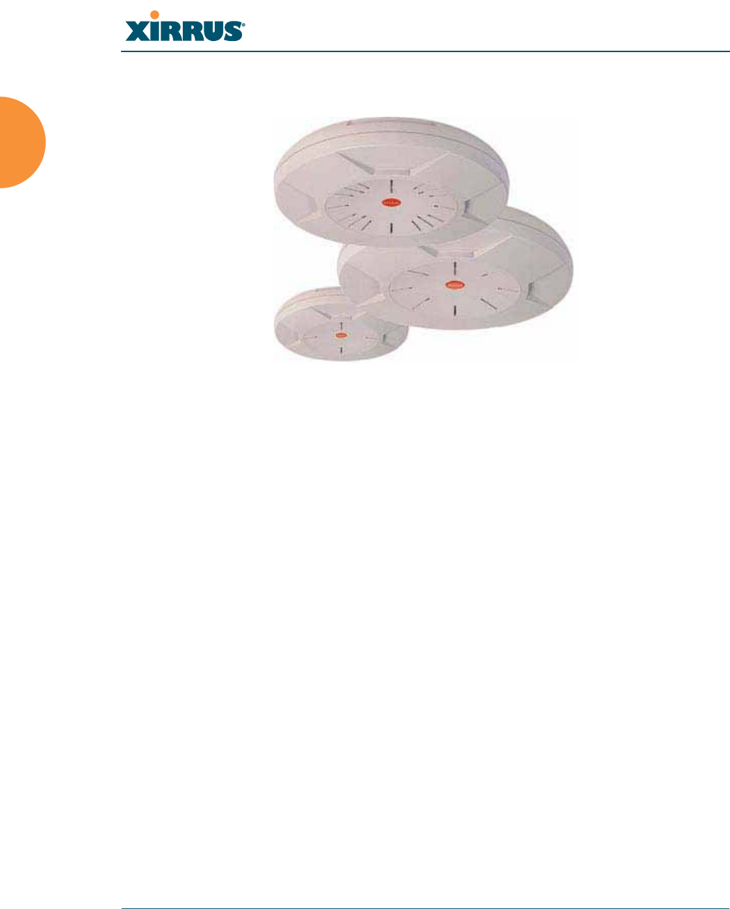
The Xirrus Family of Products
Figure 1. Xirrus Arrays
The Xirrus family of products includes the following:
z
The XS Series of Xirrus Wi-Fi Arrays (XS16 / XS12 / XS8 / XS4)
XS Arrays integrate multiple Integrated Access Points—radios with high-
gain directional antennas for increased range and coverage. The Array
also incorporates an onboard multi-gigabit switch, Wi-Fi controller, and
firewall into a single device, along with a dedicated Wi-Fi threat sensor
and an embedded spectrum analyzer. The Wi-Fi Array provides more
than enough bandwidth, security, and control to replace switched
Ethernet to the desktop as the primary network connection. The XS16 has
16 IAPs, the XS12 has 12 IAPs, the XS8 has 8 IAPs, and the XS4 has 4 IAPs.
z
The XN Series of Xirrus Wi-Fi Arrays (XN16 / XN12 / XN8 / XN4)
The newest Xirrus Wi-Fi Arrays add the speed and reach of IEEE 802.11n
technology to the XS series of Arrays. The XN Series of Arrays feature the
capacity and performance needed to replace switched Ethernet to the
desktop. The XN16 has 16 IAPs, the XN12 has 12 IAPs, the XN8 has 8
IAPs, and the XN4 has 4 IAPs.
Wi-Fi Array
Introduction 3
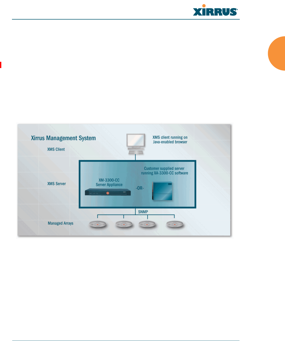
z
Xirrus Management System (XMS)
XMS is used for managing large Array deployments from a centralized
Web-based interface. The XMS server is available pre-installed on the
Xirrus XM-33xx-CC Management Platform Series, or as a software
package (XA-3300-CC) to be installed on your own server hardware.
Figure 2 illustrates the elements of the Xirrus Management System. Users
start the XMS client simply by entering the URL of the XMS server on a
web browser. The XMS server manages a number of Wi-Fi Arrays via
SNMP.
Figure 2. The Xirrus Management System
If you need detailed information about this product, refer to the XMS
User’s Guide, part number 800-0007-001.
z
Xirrus Power over Gigabit Ethernet (PoGE)
The PoGE modules eliminate the need for running separate power
cabling. Additionally, an eight port module provides distributed power
to multiple Arrays, facilitating backup power when connected via a UPS.

Wi-Fi Array
4 Introduction
Nomenclature
Throughout this User’s Guide, the Xirrus Wi-Fi Array is also referred to as simply
the Array. In some instances, the terms product and unit are also used. When
discussing specific products from the Xirrus family, the product name is used (for
example, XN16, XS12, or XS-3500). The Wi-Fi Array’s operating system is referred
to as the ArrayOS. The Web Management Interface for browser-based
management of the Array is referred to as WMI.
The XS series of Arrays have two types of radios—the 5 GHz 802.11a radios are
named a1 to a12 (for 16-port models). The 802.11a/b/g radios are named abg1 to
abg4, and they support both 2.4GHz and 5 GHz. The XN series of Arrays also
have two types of radios—the 5 GHz 802.11a/n radios are named an1 through
an12 (for 16-port models). The 802.11a/b/g/n radios are named abgn1 to abgn4,
and they also support both 2.4GHz and 5 GHz. When referring to a port that may
be on either an XN or XS model, the nomenclature abg(n) and a(n) will be used,
e.g., abg(n)2 or a(n)6.
The Xirrus Management System is referred to as XMS. The Power over Gigabit
Ethernet system may be referred to as PoGE.
About this User’s Guide
This User’s Guide provides detailed information and procedures that will enable
wireless network administrators to install, configure and manage the Wi-Fi Array
so that end users can take full advantage of the product’s features and
functionality without technical assistance.
Organization
Topics and procedures are organized by function under the following chapter
headings:
z
Introduction
Provides a brief introduction to wireless technology, an overview of the
product, including its key features and benefits, and presents the product
specifications.

Wi-Fi Array
Introduction 5
z
Installing the Wi-Fi Array
Defines prerequisites for deploying and installing the Array and provides
instructions to help you plan and complete a successful installation.
z
The Web Management Interface
Offers an overview of the product’s embedded Web Management
Interface, including its content and structure. It emphasizes what you
need to do to ensure that any configuration changes you make are
applied, and provides a list of restricted characters. It also includes
instructions for logging in to the Array with your Web browser.
z
Viewing Status on the Wi-Fi Array
Describes the status and statistics displays available on the Array using
its embedded Web Management Interface.
z
Configuring the Wi-Fi Array
Contains procedures for configuring the Array using its embedded Web
Management Interface.
z
Using Tools on the Wi-Fi Array
Contains procedures for using utility tools provided in the Web
Management Interface. It includes procedures for upgrading the system
firmware, uploading and downloading configurations and other files,
using diagnostic tools, and resetting the Array to its factory defaults.
z
The Command Line Interface
Includes the commands and the command structure used by the Wi-Fi
Array’s Command Line Interface (CLI), and provides a procedure for
establishing a Telnet connection to the Array. This chapter also includes
some sample key configuration tasks using the CLI.
z
Appendix A: Servicing the Wi-Fi Array
Contains procedures for servicing the Array, including the removal and
reinstallation of major hardware components.
z
Appendix B: Quick Reference Guide
Contains the product’s factory default settings.

Wi-Fi Array
6 Introduction
z
Appendix C: Technical Support
Offers guidance to resolve technical issues, including general hints and
tips to enhance your product experience, and a procedure for isolating
problems within an Array-enabled wireless network. Also includes
Frequently Asked Questions (FAQs) and Xirrus contact information.
z
Appendix D: Implementing PCI DSS
Discusses meeting security standards with the Array, including FIPS and
PCI DSS.
z
Appendix F: Notices
Contains the legal notices, licensing, and compliance statements for the
Array. Please read this section carefully.
z
Glossary of Terms
Provides an explanation of terms directly related to Xirrus product
technology, organized alphabetically.
z
Index
The index is a valuable information search tool. Use the index to locate
specific topics discussed in this User’s Guide. Simply click on any page
number in the index to jump to the referenced topic.
Notes and Cautions
The following symbols are used throughout this User’s Guide:
Screen Images
Some screen images of the Web Management Interface have been modified for
clarity. For example, an image may have been cropped to highlight a specific area
of the screen, and/or sample data may be included in some fields.
Your User’s Guide as a PDF Document
#This symbol is used for general notes that provide useful supplemental
information.
!This symbol is used for cautions. Cautions provide critical information that
may adversely affect the performance of the product.

Wi-Fi Array
Introduction 7
This User’s Guide is also made available as a secure PDF (Portable Document
Format) file and can be viewed using the Adobe® Acrobat Reader® product. It
cannot be edited or modified. If you don’t have Acrobat Reader, you can
downloaded it free-of-charge from: http://www.adobe.com.
Hyperlinks
If you click on body text that appears in the color TEAL (with the exception of
headings or notes) the embedded hyperlink within the text will immediately take
you to the referenced destination. All internal and external cross-references,
including page numbers within the List of Figures and the Index, have associated
hyperlinks. After “jumping” to a referenced topic, if you want to return to the
previous page (reference source), simply click on Acrobat’s previous page button.
Window or Page?
Is a window a page, or is a page a window? There seems to be some dispute as to
what the correct term should be. For the sake of consistency, this document uses
the term Window when referring to how the Wi-Fi Array’s Web Management
Interface is displayed on your monitor.
Why Choose the Xirrus Wi-Fi Array?
The deployment of wireless LANs is becoming increasingly common as
businesses strive for greater flexibility in the workplace and the need for
employee mobility rises. The only requirements for an effective wireless
deployment are a power source, a couple of screws, and a little imagination.
Wireless LAN is also fully compatible with standard Ethernet protocols, so
connectivity with existing wired infrastructures is transparent to users—they can
still access and use the same applications and network services that they use
when plugged into the company’s wired LAN infrastructure (it’s only the plug
that no longer exists).
Wireless LAN has come a long way in the past few years and now offers the
performance, reliability and security that Enterprise customers have come to
expect from their networks. The technology is being driven by four major IEEE
standards:

Wi-Fi Array
8 Introduction
z
802.11a
Operates in the 5 GHz range with a maximum speed of 54 Mbps.
z
802.11b
Operates in the 2.4 GHz range with a maximum speed of 11 Mbps.
z
802.11g
Supports a higher transmission speed of 54 Mbps in the 2.4 GHz range
and is backwards compatible with 802.11b.
z
802.11n
Uses multiple antennas per radio to boost transmission speed as high as
300 Mbps, increasing throughput, range, and maximum number of users.
802.11n is backwards compatible with 802.11a/b/g.
Whether you have just a handful of users or thousands of users, wireless has the
scalability and flexibility to serve your needs.
See Also
Key Features and Benefits
Wi-Fi Array Product Overview
Product Specifications—XN16, XN12, and XN8
Product Specifications—XS4/XS-3500
Product Specifications—XS16/XS-3900, XS12, and XS8/XS-3700
The Xirrus Family of Products
Wi-Fi Array
Introduction 9
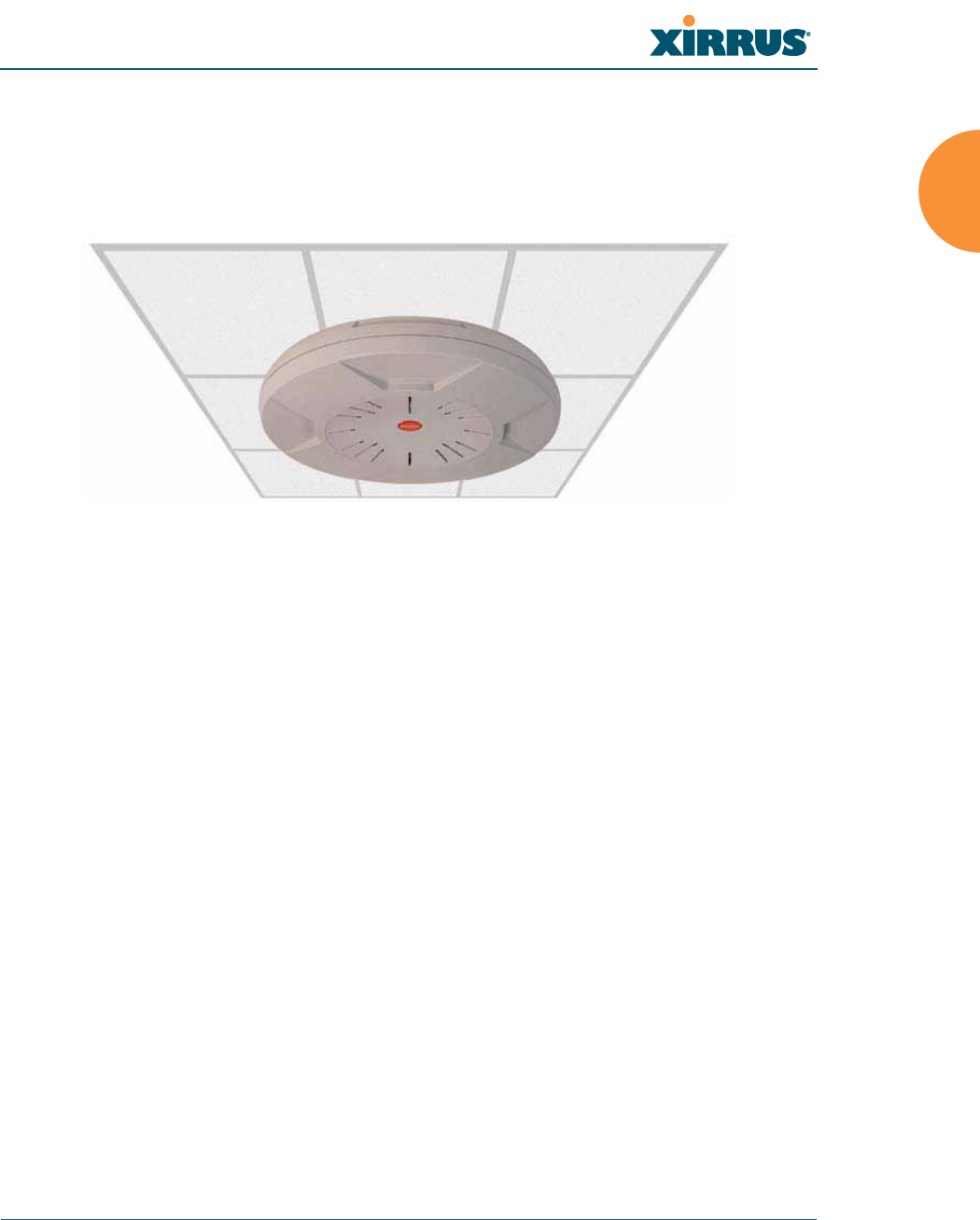
Wi-Fi Array Product Overview
Part of the family of Xirrus products, the Wi-Fi Array is a high capacity, multi-
mode device designed for the Enterprise market, with twice the range and up to
eight times the capacity of competitive wireless products.
Figure 3. Wi-Fi Array (XN16)
The Wi-Fi Array (regardless of the product model) is Wi-Fi® compliant and
simultaneously supports 802.11a, 802.11b and 802.11g clients. XN model arrays
add the enhanced abilities of 802.11n to this combination. Enterprise class features
such as VLAN support and multiple SSID capability enable robust network
compatibility and a high level of scalability and system control. The optional
Xirrus Management System (XMS) allows global management of hundreds of
Arrays from a central location.
Multiple versions of the Array with different numbers of Integrated Access Points
(IAPs) support a variety of deployment applications: 16 IAPs (XN16, XS16,
XS-3900), 12 IAPs (XN12, XS12), 8 IAPs (XN8, XS8, XS-3700), and 4 IAPs (XN4,
XS4, XS-3500).
Enterprise Class Security
The latest and most effective wireless encryption security standards, including
WPA (Wi-Fi Protected Access) and WPA2 with 802.11i AES (Advanced
Encryption Standard) are provided with the Wi-Fi Array. In addition, the use of
an embedded RADIUS server (or 802.1x with an external RADIUS server) ensures
user authentication—multiple Arrays can authenticate to the optional XMS,
ensuring only authorized Arrays become part of the wireless network. Rogue AP

Wi-Fi Array
10 Introduction
detection, site monitoring, and RF spectrum analysis are performed in the
background by the Array automatically.
Wi-Fi Array Product Family
The following tables provide an overview of the main features supported by the
Wi-Fi Array product family.
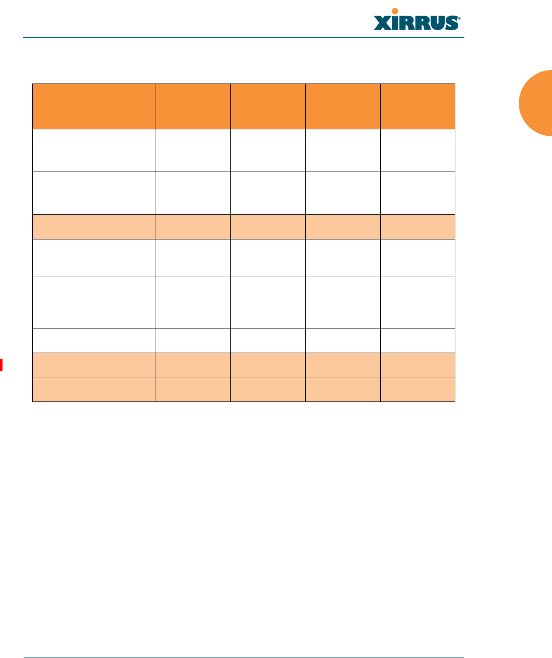
XN Family of Arrays
Feature XN16 XN12 XN8 XN4
Number of
802.11a/b/g/n radios
4444
Number of
802.11a/n radios
12840
Tota l radi os 16 12 8 4
Number of
integrated antennas
48 36 24 12
Integrated Wi-Fi switch ports 16 12 8 4
Integrated RF spectrum
analyzer, threat sensors Yes Yes Yes Yes
Uplink Ports 2221
Wi-Fi bandwidth 4.8 Gbps 3.6 Gbps 2.4 Gbps 1.2 Gbps
Users supported 1,024 768 512 256
Wi-Fi Array
Introduction 11
XS Family of Arrays
See Also
Key Features and Benefits
Wi-Fi Array Product Overview
Product Specifications—XN16, XN12, and XN8
Product Specifications—XS4/XS-3500
Product Specifications—XS16/XS-3900, XS12, and XS8/XS-3700
Power over Gigabit Ethernet (PoGE) (Optional)
Why Choose the Xirrus Wi-Fi Array?
Feature XS16,
XS-3900 XS12 XS8,
XS-3700
XS4,
XS-3500
Number of
802.11a/b/g radios
4444
Number of
802.11a radios
12840
Tota l rad ios 16 12 8 4
Integrated Wi-Fi
switch ports 16 12 8 4
Integrated RF
spectrum analyzer
and threat sensors
Yes Yes Yes Yes
Uplink Ports 2221
Wi-Fi bandwidth 864 648 432 216
Users supported 1,024 768 512 256
Wi-Fi Array
12 Introduction
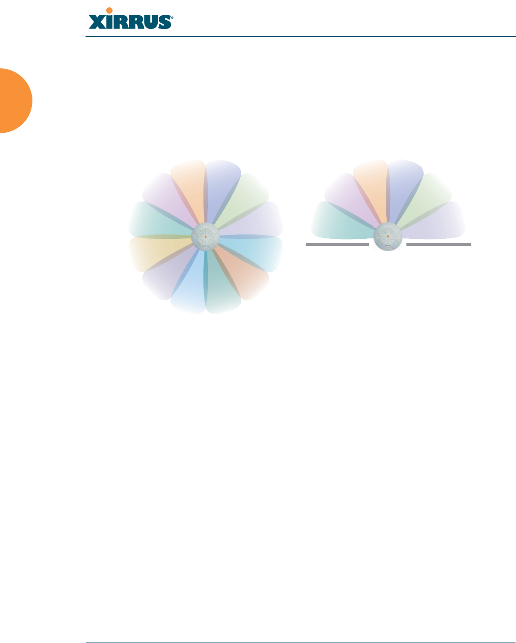
Deployment Flexibility
Xirrus’ unique multi-radio architecture generates 360 degrees of sectored high-
gain 802.11a/b/g/n or 802.11a/b/g coverage that provides extended range and
the highest possible data rates for a large volume of clients. Each sector can be
controlled automatically or manually, creating a pattern of wireless coverage
perfectly tailored to individual customer needs. For example:
Figure 4. Wireless Coverage Patterns
Figure 4 depicts the following two scenarios:
z
Full pattern coverage
All radios are activated with coverage spanning 360 degrees. If within
range, clients will always receive coverage regardless of their geographic
position relative to the Array.
z
Partial pattern coverage
If desired, the Wi-Fi Array can be deployed close to an exterior wall. In
this case, half of all available radios have been deactivated to prevent
redundant signals from “bleeding” beyond the site’s perimeter wall. This
configuration may also be used in those cases where you want to restrict
wireless coverage to selected areas of the building’s interior.
See also, “Flexible Coverage Schemes” on page 18.
outside wall
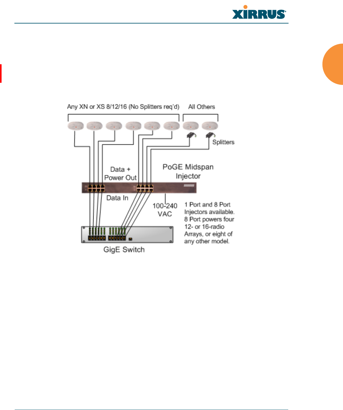
Wi-Fi Array
Introduction 13
Power over Gigabit Ethernet (PoGE) (Optional)
The Xirrus XP1 and XP8 Power over Gigabit Ethernet modules provide power to
your Arrays over the same Cat 5e or Cat 6 cable used for data, eliminating the
need to run power cables and provide an AC power outlet in proximity to each
unit.
Figure 5. XP8 - Power over Ethernet Usage
Specific models of the Array are compatible with specific PoGE modules. For
details, please see “Power over Gigabit Ethernet Compatibility Matrix” on
page 414.
See Also
Key Features and Benefits
Wi-Fi Array Product Overview
Product Specifications—XN16, XN12, and XN8
Product Specifications—XS4/XS-3500
Product Specifications—XS16/XS-3900, XS12, and XS8/XS-3700
The Xirrus Family of Products
Why Choose the Xirrus Wi-Fi Array?
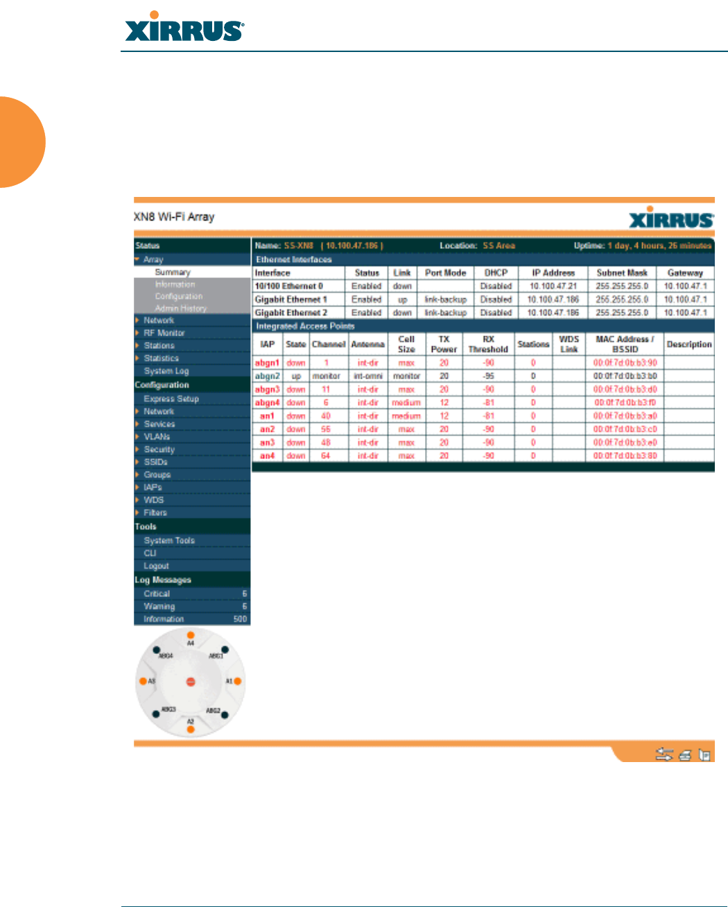
Wi-Fi Array
14 Introduction
Enterprise Class Management
The Wi-Fi Array can be configured with its default RF settings, or the RF settings
can be customized using the Array’s embedded Web Management Interface
(WMI). The WMI enables easy configuration and control from a graphical
console, along with a full compliment of troubleshooting tools and statistics.
Figure 6. WMI: Array Status
In addition, a fully featured Command Line Interface (CLI) offers IT professionals
a familiar management and control environment. SNMP (Simple Network

Wi-Fi Array
Introduction 15
Management Protocol) is also supported to allow management from an SNMP
compliant management tool, such as the optional Xirrus Management System.
See Also
Key Features and Benefits
Product Specifications—XN16, XN12, and XN8
Product Specifications—XN4
Product Specifications—XS4/XS-3500
Product Specifications—XS16/XS-3900, XS12, and XS8/XS-3700
Power over Gigabit Ethernet (PoGE) (Optional)
The Xirrus Family of Products
Why Choose the Xirrus Wi-Fi Array?
#For deployments of more than five Arrays, we recommend that you use the
Xirrus Management System (XMS). The XMS offers a rich set of features
for fine control over large deployments.
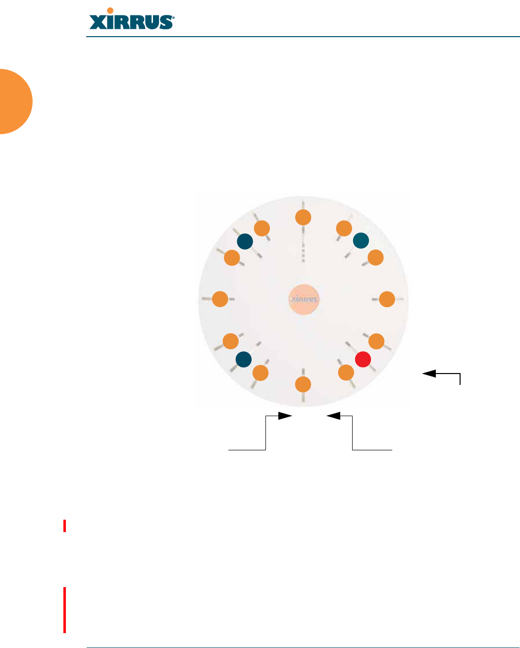
Wi-Fi Array
16 Introduction
Key Features and Benefits
This section describes some of the key product features and the benefits you can
expect when deploying the Wi-Fi Array (the XN16 product is highlighted in this
section).
High Capacity and High Performance
Figure 7. Layout of IAPs (XN16)
The XN16 version of the Wi-Fi Array (Figure 7) easily handles time-sensitive
traffic such as voice, and can enable wireless connectivity for 1,024 users. The unit
includes two Gigabit uplink ports for connection to the wired network. A total of
sixteen IAPs provides a maximum wireless capacity of 4.8 Gbps, which offers
ample reserves for the high demands of current and future applications. Of the
sixteen IAPs, twelve operate as 802.11a/n radios (5 GHz band), and four operate
as 802.11a/b/g/n radios (5 GHz or 2.4 GHz bands), providing backwards
compatibility with 802.11b and 802.11g.
an1
abgn1
an2
an3
an4
abgn2
an5
an6
an7
abgn3
an8
an9
an10
abgn4
an11
an12
Mode(s) IAP number
abgn2
(RF monitoring)
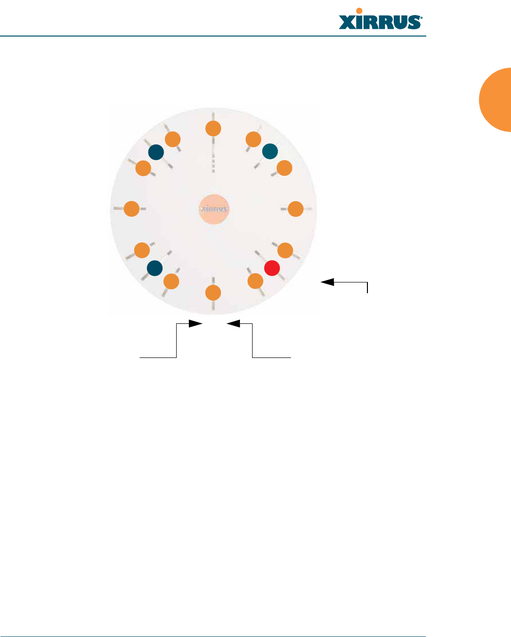
Wi-Fi Array
Introduction 17
In the recommended configuration, IAP (radio) abg(n)2 is configured in RF
monitoring and rogue AP detection mode.
Figure 8. Naming of IAPs (XS16)
Extended Coverage
One XN16 solution enables you to replace up to sixteen access points (includes
one omnidirectional IAP for monitoring the network). Fifteen IAP radios with
integrated directional antennas provide increased wireless range and enhanced
data rates in all directions. With a Wi-Fi Array deployed, far fewer access points
are needed and wired-like resiliency is delivered throughout your wireless
network. Your Wi-Fi Array deployment ensures:
z
Continuous connectivity if an IAP (radio) fails.
z
Continuous connectivity if an Array fails.
z
Continuous connectivity if a WDS link or switch fails.
z
Continuous connectivity if a Gigabit uplink or switch fails.
a1
abg1
a2
a3
a4
abg2
a5
a6
a7
abg3
a8
a9
a10
abg4
a11
a12
Mode(s) IAP number
abg2
(RF monitoring)
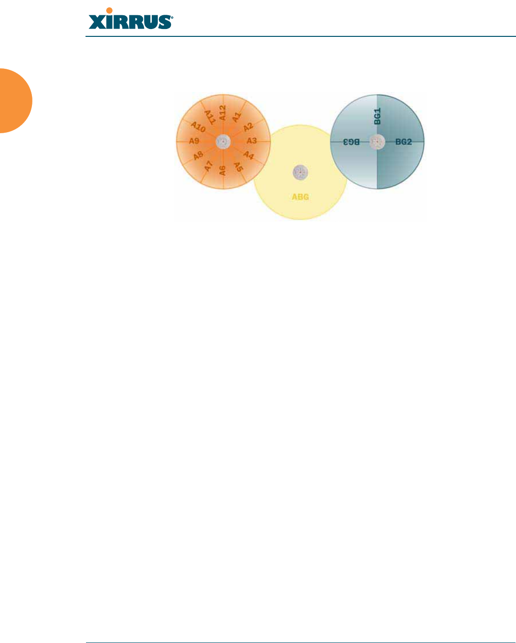
Wi-Fi Array
18 Introduction
Flexible Coverage Schemes
Your Wi-Fi Array offers flexible coverage schemes for each wireless technology.
Figure 9. Coverage Schemes
z
802.11a/n, 802.11a
Delivers 60° wireless coverage per IAP, with 6 dBi of gain.
z
802.11b/g/n, 802.11b/g
Delivers 180° wireless coverage, with 3 dBi of gain.
z
802.11a/b/g/n, 802.11a/b/g (monitor only)
Delivers 360° wireless coverage, with 2 dBi of gain.
Non-Overlapping Channels
Complete use of non-overlapping channels limits interference and delivers
maximum capacity. On the XN16, up to 16 non-overlapping channels are fully
utilized across the 5GHz and 2.4GHz spectrums (up to 12 across the 5GHz
spectrum plus up to 3 across the 2.4 GHz spectrum—typically, one additional
radio is used as a dedicated RF monitor).
Secure Wireless Access
Multiple layers of authentication and encryption ensure secure data
transmissions. The Wi-Fi Array is 802.11i compliant with encryption support for
40 bit and 128 bit WEP, WPA and WPA2 with TKIP and AES encryption.
Authentication support is provided via 802.1x, including PEAP, EAP-TLS, EAP-
TTLS, and LEAP (Lightweight Extensible Authentication Protocol) passthrough.
802.11a/n
Monitor only
802.11a/b/g/n

Wi-Fi Array
Introduction 19
Applications Enablement
QoS (Quality of Service) functionality combined with true switch capabilities
enable high density video and Voice over Wireless LAN deployments. Compliant
with 802.1p and 802.1Q standards.
SDMA Optimization
SDMA (Spatial Division Multiple Access) technology provides full 360° coverage
while allowing independent channel and power output customization. Also
supports fast inter-zone handoffs for time-sensitive applications and roaming
support.
Fast Roaming
Utilizes the Xirrus Roaming Protocol (XRP) ensuring fast and seamless roaming
capabilities between IAPs or Arrays at both Layer 2 and Layer 3.
Easy Deployment
The Xirrus Management System (XMS) offers real time monitoring and
management capabilities of the wireless network—ideal for the Enterprise
market. It also allows you to import floor plans to help you plan your
deployment. The Xirrus Wi-Fi Array chassis has a plenum rated, lockable and
tamper resistant case.
See Also
Wi-Fi Array Product Overview
Product Specifications—XN16, XN12, and XN8
Product Specifications—XS4/XS-3500)
Product Specifications—XS16/XS-3900, XS12, and XS8/XS-3700
Power over Gigabit Ethernet (PoGE) (Optional)
The Xirrus Family of Products
Why Choose the Xirrus Wi-Fi Array?
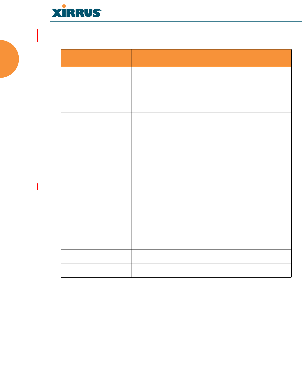
Wi-Fi Array
20 Introduction
Product Specifications—XN16, XN12, and XN8
Element Specifications
Number of Users Maximum of 64 associated users per radio
XN16: 1024 users per Array
XN12: 768 users per Array
XN8: 512 users per Array
Physical Diameter: 18.65 inches (47.37 cm)
Height: 3.87 inches (9.83 cm)
Weight: 10 lbs (3.63 kg)
Environmental Operating Temperature:
0°C to 55°C
0% to 90% relative humidity (non-condensing)
Storage Temperature:
-20°C to 60°C
5% to 95% relative humidity (non-condensing)
System 1 GHz CPU (XN16/XN12/XN8)
1 GB RAM (XN16/XN12/XN8)
1 GB system flash
Integrated Switch 2.1 Gbps integrated wireless switch
Chassis Lockable mounting plate, Kensington lock slot

Wi-Fi Array
Introduction 21
Electrical Each Array supports both AC and PoGE
AC Input Power: 100-240VAC at 50-60 Hz
PoGE (DC) Input Power: Power over Gigabit
Ethernet—no splitter required, 48VDC,
Maximum 2A
Nominal Power:
XN16: 100W
XN12: 90W
XN8: 75W
All Models:
For PoGE, see “Power over Gigabit Ethernet
Compatibility Matrix” on page 414.
Interfaces Serial Console Port:
1 x RS232 – RJ45 connector, for local
configuration
Ethernet Interfaces:
2 x Gigabit 100/1000 Mbps uplink ports for link
aggregation, redundancy, or bridging
1 x Fast Ethernet 10/100 Mbps, for out of band
management
Status LEDs:
System status, Ethernet, Radio
Networking DHCP client, DHCP server (multiple DHCP
pools), DNS Client, NTP client, NAT
Element Specifications

Wi-Fi Array
22 Introduction
Management Xirrus Management System (XMS)—Layer 3
Element Management System
HTTPS Web Management Interface (WMI)
CLI via SSHv2, Telnet, local serial Console
Enable/disable management for any interface
Read-write and read-only admin accounts may
be authenticated via RADIUS
SNMP v2c, v3
Configuration Files—text-based files may be
imported, exported, or compared
NetFlow—IP flow information (traffic statistics
may be sent to an external Collector
FTP, TFTP
Syslog reporting for alerts/alarms—messages
may be stored on internal Syslog server or sent to
up to three external syslog servers.
Cisco Discovery Protocol (CDP)—obtain protocol
addresses and platform information for
neighboring devices
Quality of Service
(QoS) Support
Multiple SSIDs:
16 unique SSIDs per Array
Each SSID beacons a unique BSSID per radio
VLAN and QoS settings for each SSID
VLANs:
Up to 16 VLANs, 802.1Q, 802.1p
Prioritization:
802.11e wireless prioritization
802.1p wired prioritization
Fair queuing of downstream traffic
Wireless Voice Support:
Spectralink Voice Priority (SVP) protocol
Element Specifications

Wi-Fi Array
Introduction 23
Security Wireless Encryption
Line speed, hardware-accelerated encryption
modes:
WPA TKIP
WPA2 AES
WEP 40/64
WEP 104/128
Wireless Authentication:
Open
Pre-shared Key
802.1X EAP
PEAP
EAP-TLS
EAP-TTLS
EAP-LEAP Pass-through
Web Page Redirect (Captive Portal)
MAC Address Access Control List (ACL)
CHAP, PAP
Firewall:
Integrated stateful-inspection, rules-based
firewall
IDS/IPS:
Integrates with Xirrus XDM Intrusion Detection/
Prevention System for real-time wireless security
protection
Rogue AP detection and blocking:
Integrated Rogue AP detection and alerting via
dedicated internal RF Threat Sensor. Rogue AP
can be shielded
Integrated RADIUS Server:
Integrated 802.1x Authentication Server
supporting EAP-PEAP
Element Specifications

Wi-Fi Array
24 Introduction
Security
(continued)
Time of Day Access:
Specify when access is allowed, per SSID or User
Group
Station-Station Blocking:
Station-to-Station traffic blocking option
Wireless Wireless Standards:
802.11a
802.11b
802.11d
802.11g
802.11e
802.11h
802.11i
802.11j
802.11n
Number of Radios:
XN16: 12 x 802.11a/n radios
4 x 802.11a/b/g/n radios
Only 12 radios should be used as 802.11a/n
radios (i.e., 5 GHz band) concurrently.
48 integrated antennas
XN12: 8 x 802.11a/n radios
4 x 802.11a/b/g/n radios
36 integrated antennas
XN8: 4 x 802.11a/n radios
4 x 802.11a/b/g/n radios
24 integrated antennas
Spectrum Analyzer:
1 integrated into Array
Element Specifications

Wi-Fi Array
Introduction 25
Wireless
(continued)
Frequency Bands:
11a/n: 4.945 – 4.985 (restricted Public Safety
band)
11a/n: 5.15-5.25 GHz (UNII 1)
11a/n: 5.15-5.25 GHz (TELEC)
11a/n: 5.25-5.35 GHz (UNII 2)
11a/n: 5.470-5.725 (ETSI)
11a/n: 5.725-5.825 GHz (UNII 3)
11b/g/n: 2.412-2.462 GHz (FCC)
11b/g/n: 2.412-2.472 GHz (ETSI)
11b/g/n: 2.412-2.484 GHz (TELEC)
Channel Selection:
Manual and Automatic
802.11a/n Antennas
Integrated 6dBi, sectorized
802.11b/g/n Antennas
Integrated 3dBi, sectorized
Wi-Fi Monitoring:
1 Integrated Access Point can be set as a
dedicated Wi-Fi Threat Sensor
2 dBi 360° omni-directional antenna
802.11a/b/g/n External Antenna Connectors:
3 RP-TNC connectors
Performance Client Load Balancing
Automatic load balancing between system radios
Element Specifications
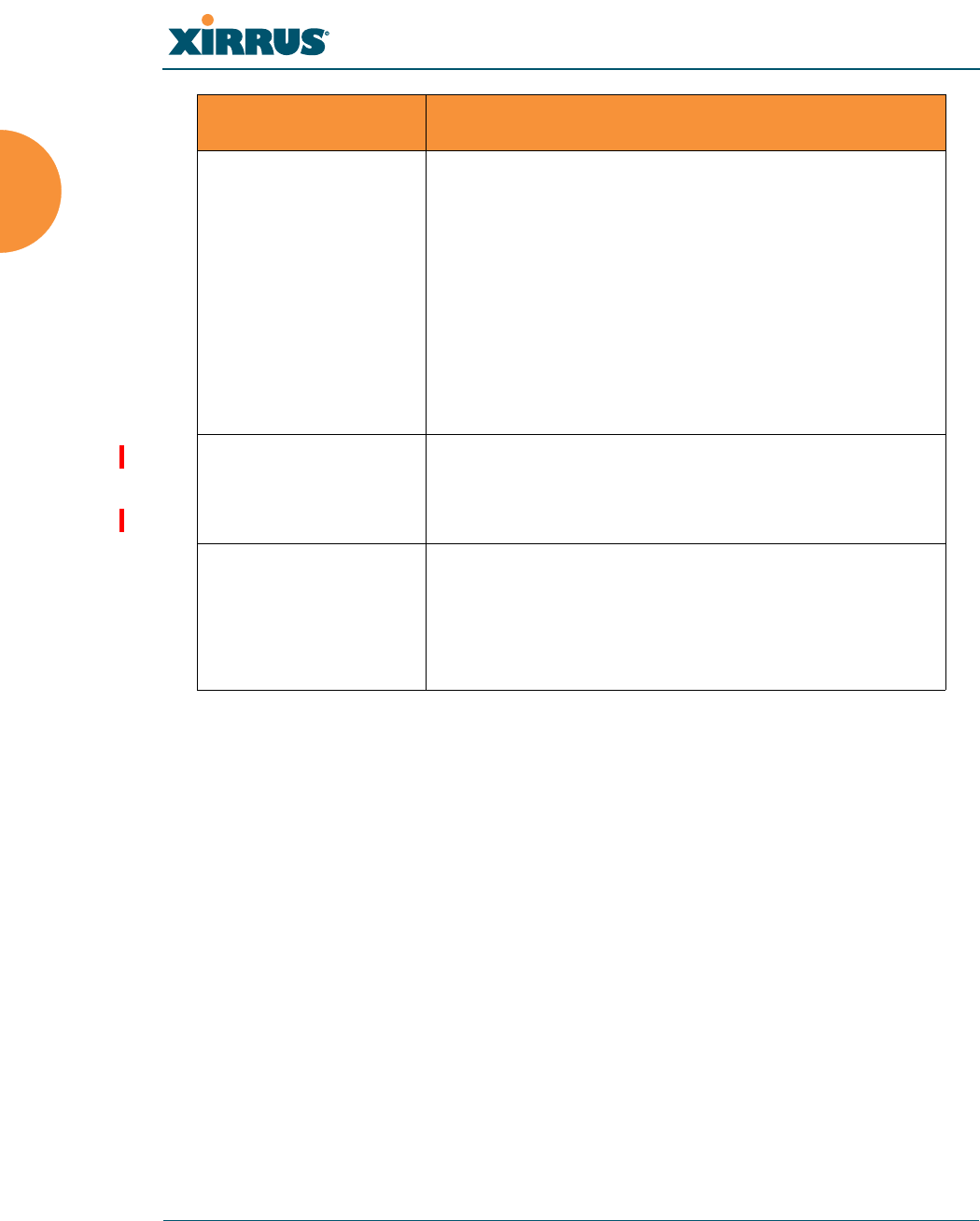
Wi-Fi Array
26 Introduction
See Also
Key Features and Benefits
Wi-Fi Array Product Overview
Product Specifications—XN4
Product Specifications—XS16/XS-3900, XS12, and XS8/XS-3700
Product Specifications—XS4/XS-3500
Power over Gigabit Ethernet (PoGE) (Optional)
The Xirrus Family of Products
Why Choose the Xirrus Wi-Fi Array?
Compliance Electromagnetic:
ICES-003 (Canada)
EN 301.893 (Europe)
EN 301.489-1 and -17 (Europe)
Safety:
EN 60950
EN 50371 to 50385
CE Mark
Certifications Wi-Fi Alliance: 802.11a/b/g, WPA, WPA2, and
extended EAP types. Our certifications may be
viewed here.
Warranty Hardware:
Five Year Standard (extendable)
Software:
90 Days Standard (extendable)
Element Specifications

Wi-Fi Array
Introduction 27
Product Specifications—XN4
Element Specifications
Number of Users Maximum of 64 associated users per radio,
256 users per XN4
Physical Diameter: 12.58 inches (31.95 cm)
Height: 2.58 inches (6.55 cm)
Weight: 4lbs (1.81 kg)
Environmental Operating Temperature:
0°C to 55°C
0% to 90% relative humidity (non-condensing)
Storage Temperature:
-20°C to 60°C
5% to 95% relative humidity (non-condensing)
System 1 GHz CPU
512 MB RAM
1 GB system flash
Integrated Switch 2.1 Gbps integrated wireless switch
Chassis Lockable mounting plate, Kensington lock slot
Electrical XN4 supports Power over Gigabit Ethernet
(PoGE) only, no splitter required
PoGE (DC) Input Power: 48VDC, Maximum 2A
Nominal Power: 60 W
For PoGE, see “Power over Gigabit Ethernet
Compatibility Matrix” on page 414.

Wi-Fi Array
28 Introduction
Interfaces Serial Console Port:
1 x RS232 – RJ45 connector, for local
configuration
Ethernet Interfaces:
1 x Gigabit 100/1000 Mbps uplink port
Status LEDs:
System status, Ethernet, Radio
Networking DHCP client, DHCP server (multiple DHCP
pools), DNS Client, NTP client, NAT
Management Xirrus Management System (XMS)—Layer 3
Element Management System
HTTPS Web Management Interface (WMI)
CLI via SSHv2, Telnet, local serial Console
Enable/disable management for any interface
Read-write and read-only admin accounts may
be authenticated via RADIUS
SNMP v2c, v3
Configuration Files—text-based files may be
imported, exported, or compared
NetFlow—IP flow information (traffic statistics
may be sent to an external Collector
FTP, TFTP
Syslog reporting for alerts/alarms—messages
may be stored on internal Syslog server or sent to
up to three external syslog servers.
Cisco Discovery Protocol (CDP)—obtain protocol
addresses and platform information for
neighboring devices
Element Specifications

Wi-Fi Array
Introduction 29
Quality of Service
(QoS) Support
Multiple SSIDs:
16 unique SSIDs per Array
Each SSID beacons a unique BSSID per radio
VLAN and QoS settings for each SSID
VLANs:
Up to 16 VLANs, 802.1Q, 802.1p
Prioritization:
802.11e wireless prioritization
802.1p wired prioritization
Fair queuing of downstream traffic
Wireless Voice Support:
Spectralink Voice Priority (SVP) protocol
Element Specifications

Wi-Fi Array
30 Introduction
Security Wireless Encryption
Line speed, hardware-accelerated encryption
modes:
WPA TKIP
WPA2 AES
WEP 40/64
WEP 104/128
Wireless Authentication:
Open
Pre-shared Key
802.1X EAP
PEAP
EAP-TLS
EAP-TTLS
EAP-LEAP Pass-through
Web Page Redirect (Captive Portal)
MAC Address Access Control List (ACL)
CHAP, PAP
Firewall:
Integrated stateful-inspection, rules-based
firewall
IDS/IPS:
Integrates with Xirrus XDM Intrusion Detection/
Prevention System for real-time wireless security
protection
Rogue AP detection and blocking:
Integrated Rogue AP detection and alerting via
dedicated internal RF Threat Sensor. Rogue AP
can be shielded
Integrated RADIUS Server:
Integrated 802.1x Authentication Server
supporting EAP-PEAP
Element Specifications

Wi-Fi Array
Introduction 31
Security
(continued)
Time of Day Access:
Specify when access is allowed, per SSID or User
Group
Station-Station Blocking:
Station-to-Station traffic blocking option
Wireless Wireless Standards:
802.11a
802.11b
802.11d
802.11g
802.11e
802.11h
802.11i
802.11j
802.11n
Number of Radios:
XN4: 4 x 802.11a/b/g/n radios
12 integrated antennas
Spectrum Analyzer:
1 integrated into Array
Element Specifications

Wi-Fi Array
32 Introduction
Wireless
(continued)
Frequency Bands:
11a/n: 4.945 – 4.985 (restricted Public Safety
band)
11a/n: 5.15-5.25 GHz (UNII 1)
11a/n: 5.15-5.25 GHz (TELEC)
11a/n: 5.25-5.35 GHz (UNII 2)
11a/n: 5.470-5.725 (ETSI)
11a/n: 5.725-5.825 GHz (UNII 3)
11b/g/n: 2.412-2.462 GHz (FCC)
11b/g/n: 2.412-2.472 GHz (ETSI)
11b/g/n: 2.412-2.484 GHz (TELEC)
Channel Selection:
Manual and Automatic
802.11a/n Antennas
Integrated 6dBi, sectorized
802.11b/g/n Antennas
Integrated 3dBi, sectorized
Wi-Fi Monitoring:
1 Integrated Access Point can be set as a
dedicated Wi-Fi Threat Sensor
2 dBi 360° omni-directional antenna
802.11a/b/g/n External Antenna Connectors:
1 RP-TNC connector
Performance Client Load Balancing
Automatic load balancing between system radios
Element Specifications

Wi-Fi Array
Introduction 33
See Also
Key Features and Benefits
Wi-Fi Array Product Overview
Product Specifications—XN16, XN12, and XN8
Product Specifications—XS16/XS-3900, XS12, and XS8/XS-3700
Product Specifications—XS4/XS-3500
Power over Gigabit Ethernet (PoGE) (Optional)
The Xirrus Family of Products
Why Choose the Xirrus Wi-Fi Array?
Compliance Electromagnetic:
ICES-003 (Canada)
EN 301.893 (Europe)
EN 301.489-1 and -17 (Europe)
Safety:
EN 60950
EN 50371 to 50385
CE Mark
Certifications Wi-Fi Alliance: 802.11a/b/g, WPA, WPA2, and
extended EAP types. Our certifications may be
viewed here.
Warranty Hardware:
Five Year Standard (extendable)
Software:
90 Days Standard (extendable)
Element Specifications

Wi-Fi Array
34 Introduction
Product Specifications—XS16/XS-3900, XS12, and
XS8/XS-3700
Element Specifications
Number of Users Maximum of 64 associated users per radio
1024 users per Array (XS16/XS-3900)
768 users per Array (XS12)
512 users per Array (XS8/XS-3700)
Physical Diameter: 18.65 inches (47.37 cm)
Height: 3.87 inches (9.83 cm)
Weight: 8lbs (3.63 kg)
Environmental Operating Temperature:
-10°C to 50°C
0% to 90% relative humidity (non-condensing)
Storage Temperature:
-20°C to 60°C
5% to 95% relative humidity (non-condensing)
System XS16/XS12/XS8:
1 GHz CPU
1 GB RAM
1 GB system flash
Expansion slot for future options
XS-3900/XS-3700:
825 MHz CPU
512 MB RAM (XS-3900/XS-3700)
512 MB system flash
Expansion slot for future options

Wi-Fi Array
Introduction 35
Interfaces Serial:
1 x RS232 – RJ45 connector
Ethernet Interfaces:
2 x Gigabit 100/1000 Mbps w/failover
1 x Fast Ethernet 10/100 Mbps
Status LEDs:
System status, Ethernet, Radio
Electrical XS16/XS12/XS8:
Each Array supports both AC and PoGE
AC Input Power: 90-265VAC at 47-63Hz
PoGE Input Power: Power over Gigabit
Ethernet—no splitter required, 48VDC
XS-3900/XS-3700:
Separate AC and DC versions
Input Power (AC version): 90VAC to 265VAC at
47Hz to 63Hz
Input Power (DC version): 48VDC
PoGE: requires modified DC version and
splitter.
All Models:
For PoGE, see “Power over Gigabit Ethernet
Compatibility Matrix” on page 414.
Networking DHCP client, DHCP server, NTP client, NAT
VLAN Support 802.1Q, 802.1p VLAN
Supports up to 16 VLANs
Multiple SSID
Support
Allows up to 16 separate SSIDs to be defined
with map security, VLAN and QoS settings for
each SSID
Element Specifications

Wi-Fi Array
36 Introduction
Performance Client Load Balancing
Automatic load balancing between system
radios
Quality of Service:
802.1p wired traffic prioritization
Wireless packet prioritization
MAP CoS to TCID
Fair queuing of downstream traffic
Security Wireless Security:
WEP 40bit/128bit encryption
WPA and WPA2 with TKIP and AES encryption
Rogue AP detection, with alerts and
classification
User and System Authentication:
WPA and WPA2 Pre-Shared Key authentication
Internal RADIUS Server, supports EAP-PEAP
only
802.1x EAP-TLS
802.1x EAP-TTLS/MSCHAPv2
802.1x PEAPv0/EAP-MSCHAPv2
802.1x PEAPv1/EAP-GTC
802.1x EAP-SIM
802.1x EAP-LEAP Passthrough
External RADIUS servers
Authentication of Wi-Fi Arrays to the Xirrus
Management System (XMS)
Element Specifications

Wi-Fi Array
Introduction 37
Wireless Number of Radios:
XS16/XS-3900: 12 x 802.11a radios
4 x 802.11a/b/g radios
Only 12 radios should be used as 802.11a
radios concurrently.
XS12: 8 x 802.11a radios
4 x 802.11a/b/g radios
XS8/XS-3700: 4 x 802.11a radios
4 x 802.11a/b/g radios
Wireless Standards:
802.11a/b/g and g-only mode
802.11e, 802.11i
Channel Selection:
Manual and Automatic
Frequency Bands:
11a: 4.945 – 4.985 (restricted Public Safety band)
11a: 5.15-5.25 GHz (UNII 1)
11a: 5.15-5.25 GHz (TELEC)
11a: 5.25-5.35 GHz (UNII 2)
11a: 5.470-5.725 (ETSI)
11a: 5.725-5825 GHz (UNII 3)
11b/g: 2.412-2.462 GHz (FCC)
11b/g: 2.412-2.472 GHz (ETSI)
11b/g: 2.412-2.484 GHz (TELEC)
Antennas (XS16/XS-3900):
12 x internal 6 dBi 60° 802.11a sectorized
4 x internal 3 dBi 180° 802.11b/g sectorized
1 x internal 2 dBi 360° omni-directional (for RF
monitoring)
3 x external RP-TNC connectors for three
802.11a/b/g radios
Element Specifications

Wi-Fi Array
38 Introduction
Wireless
(continued)
Antennas (XS12):
8 x internal 6 dBi 60° 802.11a sectorized
4 x internal 3 dBi 180° 802.11b/g sectorized
1 x internal 2 dBi 360° omni-directional (for RF
monitoring)
3 x external RP-TNC connectors for three
802.11a/b/g radios
Antennas (XS8/XS-3700):
4 x internal 6 dBi 60° 802.11a sectorized
4x internal 3 dBi 180° 802.11b/g sectorized
1 x internal 2 dBi 360° omni-directional (for RF
monitoring)
3 x external RP-TNC connectors for three
802.11a/b/g radios
Radio Approvals:
FCC (United States) and EN 301.893 (Europe)
Management Web-based HTTPS
SNMP v2c, v3
CLI via SSHv2 or Telnet
FTP
TFTP
Serial
Xirrus Management System (XMS)
Syslog reporting for alerts/alarms
Compliance UL / cUL 60950 and EN 60950
FCC Part 15.107 and 15109, Class A
EN 301.489 (Europe)
EN60601 EU medical equipment directive for
EMC
Element Specifications

Wi-Fi Array
Introduction 39
See Also
Key Features and Benefits
Wi-Fi Array Product Overview
Product Specifications—XN4
Product Specifications—XN16, XN12, and XN8
Product Specifications—XS4/XS-3500
Power over Gigabit Ethernet (PoGE) (Optional)
The Xirrus Family of Products
Why Choose the Xirrus Wi-Fi Array?
Product Specifications—XS4/XS-3500
Certifications Wi-Fi Alliance: 802.11a/b/g, WPA, WPA2, and
extended EAP types. Our certifications may be
viewed here.
Federal Information Processing Standard (FIPS)
Publication 140 -2, Level 2.
Warranty One year (hardware and software)
Element Specifications
Number of Users Maximum of 64 associated users per radio (256
users per Array)
Physical Diameter: 12.58 inches (31.95 cm)
Height: 2.58 inches (6.55 cm)
Weight: 4lbs (1.81 kg)
Element Specifications

Wi-Fi Array
40 Introduction
Environmental Operating Temperature:
-10°C to 50°C
0% to 90% relative humidity (non-condensing)
Storage Temperature:
-20°C to 60°C
5% to 95% relative humidity (non-condensing)
System 825 MHz CPU (XS4)
666 MHz CPU (XS-3500)
512 MB RAM, expandable (XS4)
256 MB RAM, expandable (XS-3500)
512 MB system flash, expandable
Expansion slot for future options
Electrical XS4:
Each Array supports both AC and PoGE
AC Input Power: 90-265VAC at 47-63Hz
XS-3500:
AC Input Power: 90-265VAC at 47-63Hz
Input Power (DC version): 48VDC
All Models:
Power over Gigabit Ethernet (PoGE): all 4-port
models work with all Xirrus PoGE modules,
splitter required, 48VDC
See “Power over Gigabit Ethernet
Compatibility Matrix” on page 414.
Element Specifications

Wi-Fi Array
Introduction 41
Interfaces Serial:
1 x RS232 – RJ45 connector
Ethernet Interfaces:
1 x Gigabit 100/1000 Mbps
Status LEDs:
System status, Ethernet, Radio
Management Web-based HTTPS
SNMP v2c, v3
CLI via SSHv2 or Telnet
FTP
TFTP
Serial
Xirrus Management System (XMS)
Syslog reporting for alerts/alarms
Networking DHCP client, DHCP server, NTP client, NAT
VLAN Support 802.1Q, 802.1p VLAN
Supports up to 16 VLANs
Multiple SSID
Support
Allows up to 16 separate SSIDs to be defined
with map security, VLAN and QoS settings for
each SSID
Performance Client Load Balancing
Automatic load balancing between system
radios
Quality of Service:
802.1p wired traffic prioritization
Wireless packet prioritization
MAP CoS to TCID
Fair queuing of downstream traffic
Element Specifications

Wi-Fi Array
42 Introduction
Security Wireless Security:
WEP 40bit/128bit encryption
WPA and WPA2 with TKIP and AES encryption
Rogue AP detection, with alerts and
classification
User and System Authentication:
WPA Pre-Shared Key authentication
Internal RADIUS Server, supports EAP-PEAP
only
802.1x EAP-TLS
802.1x EAP-TTLS/MSCHAPv2
802.1x PEAPv0/EAP-MSCHAPv2
802.1x PEAPv1/EAP-GTC
802.1x EAP-SIM
802.1x EAP-LEAP Passthrough
External RADIUS servers
Authentication of Wi-Fi Arrays to the Xirrus
Management System (XMS)
Element Specifications

Wi-Fi Array
Introduction 43
Wireless Number of Radios:
4 x 802.11a/b/g radios
Wireless Standards:
802.11a/b/g and g-only mode
802.11e, 802.11i
Channel Selection:
Manual and Automatic
Frequency Bands:
11a: 4.945 – 4.985 (restricted Public Safety band)
11a: 5.15-5.25 GHz (UNII 1)
11a: 5.15-5.25 GHz (TELEC)
11a: 5.25-5.35 GHz (UNII 2)
11a: 5.470-5.725 (ETSI)
11a: 5.725-5825 GHz (UNII 3)
11b/g: 2.412-2.462 GHz (FCC)
11b/g: 2.412-2.472 GHz (ETSI)
11b/g: 2.412-2.484 GHz (TELEC)
Antennas (XS-3500):
4 x internal 3 dBi 180° 802.11b/g sectorized
1 x internal 2 dBi 360° omni-directional (for RF
monitoring)
1 x external RP-TNC connector for one 802.11a/
b/g radio
Radio Approvals:
FCC (United States) and EN 301.893 (Europe)
Compliance UL / cUL 60950 and EN 60950
FCC Part 15.107 and 15109, Class A
EN 301.489 (Europe)
EN60601 EU medical equipment directive for
EMC
Element Specifications

Wi-Fi Array
44 Introduction
See Also
Key Features and Benefits
Wi-Fi Array Product Overview
Product Specifications—XN16, XN12, and XN8
Product Specifications—XN4
Product Specifications—XS16/XS-3900, XS12, and XS8/XS-3700
Power over Gigabit Ethernet (PoGE) (Optional)
The Xirrus Family of Products
Why Choose the Xirrus Wi-Fi Array?
Certifications Wi-Fi Alliance: 802.11a/b/g, WPA, WPA2, and
extended EAP types. Our certifications may be
viewed here.
Federal Information Processing Standard (FIPS)
Publication 140 -2, Level 2.
Warranty One year (hardware and software)
Element Specifications

Wi-Fi Array
Installing the Wi-Fi Array 45
Installing the Wi-Fi Array
The instructions for completing a successful installation include the following
topics:
z
“Installation Prerequisites” on page 45.
z
“Planning Your Installation” on page 48.
z
“Installation Workflow” on page 80.
z
“Unpacking the Wi-Fi Array” on page 81.
z
“Installing Your Wi-Fi Array” on page 83.
z
“Powering Up the Wi-Fi Array” on page 107.
z
“Establishing Communication with the Array” on page 110.
z
“Performing the Express Setup Procedure” on page 112.
Installation Prerequisites
Your Wi-Fi Array deployment requires the presence of hardware and services in
the host wired/wireless network, including:
z
Power Source
Most Arrays are powered via Xirrus Power over Gigabit Ethernet. PoGE
supplies power over the same Cat 5e or Cat 6 cable used for data, thus
reducing cabling and installation effort. PoGE power injector modules are
available in 1 port and 8 port configurations and are typically placed near
your Gigabit Ethernet switch. An AC outlet is required for each injector
module. Current Array models have integrated splitters, so no separate
splitter is required.
Specific models of the Array are compatible with specific PoGE modules.
For details, please see “Power over Gigabit Ethernet Compatibility
Matrix” on page 414.
If your Arrays are equipped to accept AC power (and you are not using
PoGE), you need a dedicated power outlet to supply AC power to each
unit deployed at the site.

Wi-Fi Array
46 Installing the Wi-Fi Array
z
Ethernet port
You need at least one 100/1000 BaseT port to establish wired Gigabit
Ethernet connectivity (via the product’s Gigabit 1 or Gigabit 2 port) and
one 10/100 BaseT port (if desired) for product management.
z
Secure Shell (SSH) utility
To establish secure remote command line access to the Array, you need a
Secure Shell (SSH) utility, such as PuTTY. The utility must be configured
to use SSH-2, since the Array will only allow SSH-2 connections.
z
Secure Web browser
Either Internet Explorer (version 6.0 or higher), Netscape Navigator
(version 7.0 or higher), or Mozilla Firefox (version 1.01 or higher).
A secure Web browser is required for Web-based management of the
Array. The browser must be on the same subnet as the Array, or you must
set a static route for management as described in the warning above.
z
Serial connection capability
To connect directly to the console port on the Array, your computer must
be equipped with a male 9-pin serial port and terminal emulation
software (for example, HyperTerminal). The Xirrus Array only supports
serial cable lengths up to 25’ per the RS-232 specification.
!The Array’s Ethernet ports should be connected to an Ethernet switch, not
an Ethernet hub—if a hub is used, we recommend that you connect only
one Ethernet port.
!The Gigabit1 Ethernet interface is the primary port for both data and
management traffic. If a single Ethernet connection is used, it must be
connected to the Gigabit1 Ethernet interface. See also, “Port Failover
Protection” on page 67.
The 10/100 Ethernet Port may be used for managing the Array out of
band from the Gigabit Ethernet ports. The 10/100 port will route only
management traffic, using a static route that may be configured for this
interface. See “interface” on page 336.
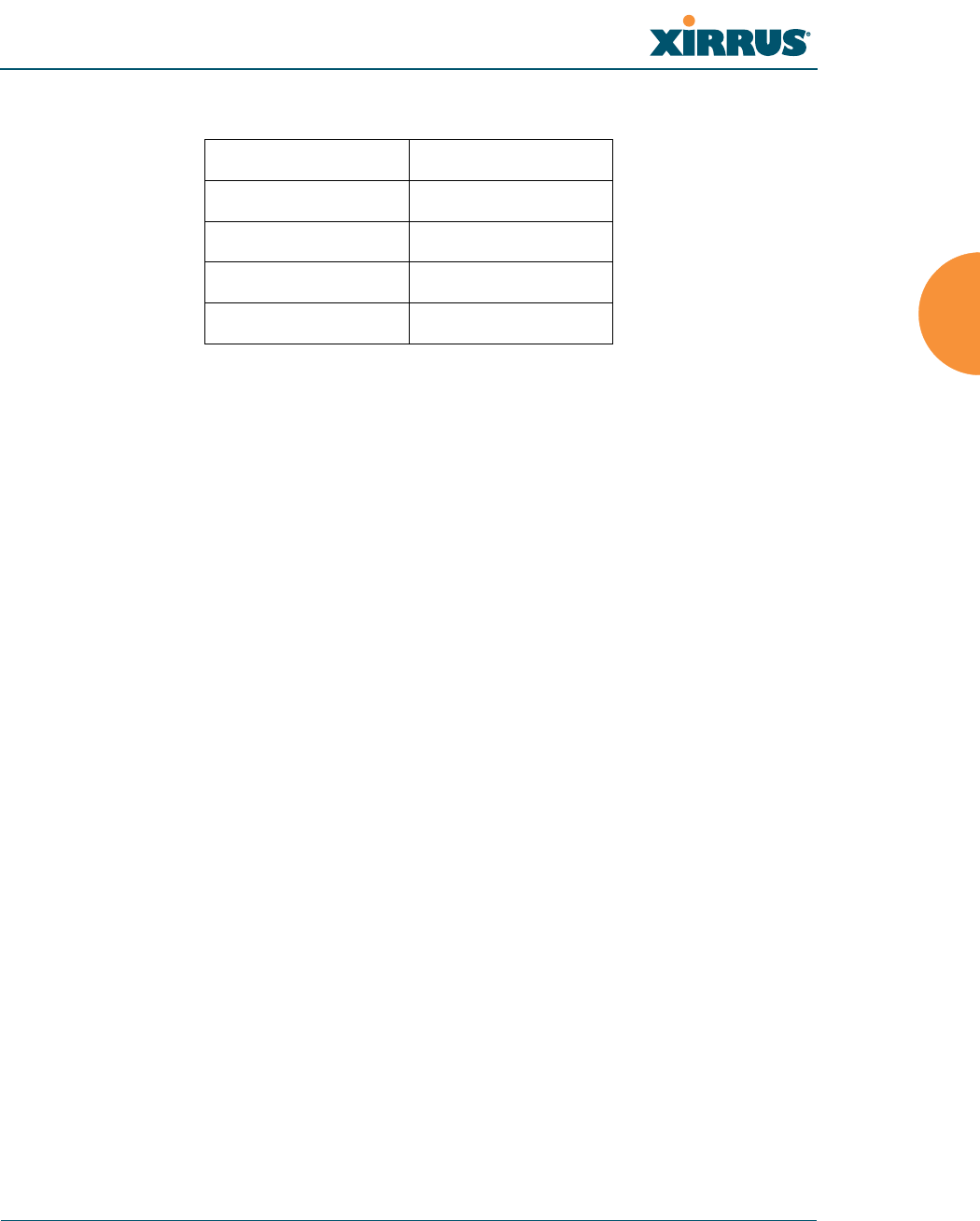
Wi-Fi Array
Installing the Wi-Fi Array 47
Use the following settings when establishing a serial connection:
Optional Network Components
The following network components are optional.
z
Xirrus Management System (XMS)
The optional XMS offers powerful management features for small or large
Wi-Fi Array deployments.
z
External RADIUS server
Although your Array comes with an embedded RADIUS server, for
802.1x authentication in large deployments you may want to add an
external RADIUS server.
Client Requirements
The Wi-Fi Array should only be used with Wi-Fi certified client devices.
See Also
Coverage and Capacity Planning
Deployment Examples
Failover Planning
Planning Your Installation
Bits per second 115,200
Data bits 8
Parity None
Stop bits 1
Flow control None

Wi-Fi Array
48 Installing the Wi-Fi Array
Planning Your Installation
This section provides guidelines and examples to help you plan your Xirrus Wi-Fi
Array deployment to achieve the best overall coverage and performance. We
recommend you conduct a site survey to determine the best location and settings
for each Array you install.
The following topics are discussed:
z
“General Deployment Considerations” on page 48
z
“Coverage and Capacity Planning” on page 50
z
“IEEE 802.11n Deployment Considerations” on page 59
z
“Failover Planning” on page 67
z
“Power Planning” on page 69
z
“Security Planning” on page 70
z
“Port Requirements” on page 72
z
“Network Management Planning” on page 75
z
“WDS Planning” on page 76
z
“Common Deployment Options” on page 79
General Deployment Considerations
The Wi-Fi Array’s unique multi-radio architecture generates 360 degrees of
sectored high-gain 802.11a/b/g/n or 802.11a/b/g coverage that provides
extended range. However, the number, thickness and location of walls, ceilings or
other objects that the wireless signals must pass through may affect the range.
Typical ranges vary depending on the types of materials and background RF
(radio frequency) noise at your location. To maximize wireless range, follow these
basic guidelines:
1. Keep the number of walls and ceilings between the Array and your
receiving devices to a minimum—each wall or ceiling can reduce the
#For a complete discussion of implementing Voice over Wi-Fi on the Array,
see the Xirrus Voice over Wi-Fi Application Note in the Xirrus Library.
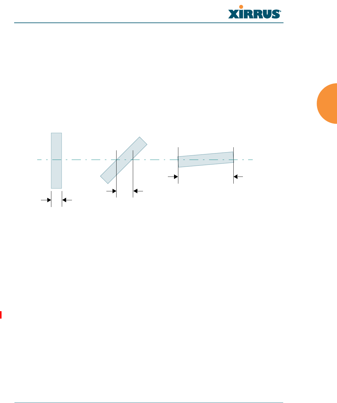
Wi-Fi Array
Installing the Wi-Fi Array 49
wireless range from between 3 and 90 feet (1 to 30 meters). Position your
devices so that the number of walls or ceilings is minimized.
2. Be aware of the direct line between each device. For example, a wall that
is 1.5 feet thick (half a meter) at 90° is actually almost 3 feet thick (or 1
meter) when viewed at a 45° angle. At an acute 2° degree angle the same
wall is over 42 feet (or 14 meters) thick! For best reception, try to ensure
that your wireless devices are positioned so that signals will travel
straight through a wall or ceiling.
Figure 10. Wall Thickness Considerations
3. Try to position wireless client devices so that the signal passes through
drywall (between studs) or open doorways and not other materials that
can adversely affect the wireless signal.
See Also
Coverage and Capacity Planning
Deployment Examples
Common Deployment Options
Installation Prerequisites
90° 45°
1.5 feet/
.5 m
~ 3 feet/
1 m
> 42 feet\
14 m
2°
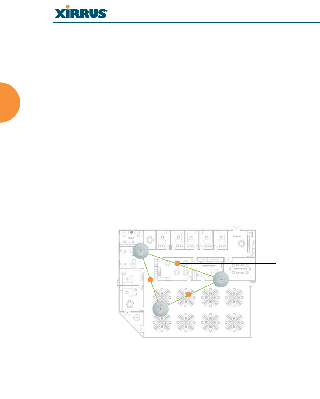
Wi-Fi Array
50 Installing the Wi-Fi Array
Coverage and Capacity Planning
This section considers coverage and capacity for your deployment(s), including
placement options, RF patterns and cell sizes, area calculations, roaming
considerations, and channel allocations.
Placement
Use the following guidelines when considering placement options:
1. The best placement option for the Array is ceiling-mounted within an
open plan environment (cubicles rather than fixed walls).
2. Keep the Array away from electrical devices or appliances that generate
RF noise. Because the Array is generally mounted on ceilings, be aware of
its position relative to lighting (especially fluorescent lighting)—we
recommend maintaining a distance of at least 3 to 6 feet (1 to 2 meters).
3. If using multiple Arrays in the same area, maintain a distance of at least
100 ft/30m between Arrays if there is direct line-of-sight between the
units, or at least 50 ft/15m if a wall or other barrier exists between the
units.
Figure 11. Unit Placement
100 ft/ 30m
100 ft/ 30 m
100 ft/
30 m

Wi-Fi Array
Installing the Wi-Fi Array 51
RF Patterns
The Wi-Fi Array allows you to control—automatically or manually—the pattern
of wireless coverage that best suits your deployment needs. You can choose to
operate with full coverage, half coverage, or custom coverage (by enabling or
disabling individual sectors).
Full (Normal) Coverage
In normal operation, the Array provides a full 360 degrees of coverage.
Figure 12. Full (Normal) Coverage
Half Coverage
If installing a unit close to an exterior wall, you can deactivate half of the radios to
prevent redundant signals from “bleeding” beyond the wall and extending
service into public areas. The same principle applies if you want to restrict service
to an adjacent room within the site.
Figure 13. Adjusting RF Patterns
outside wall
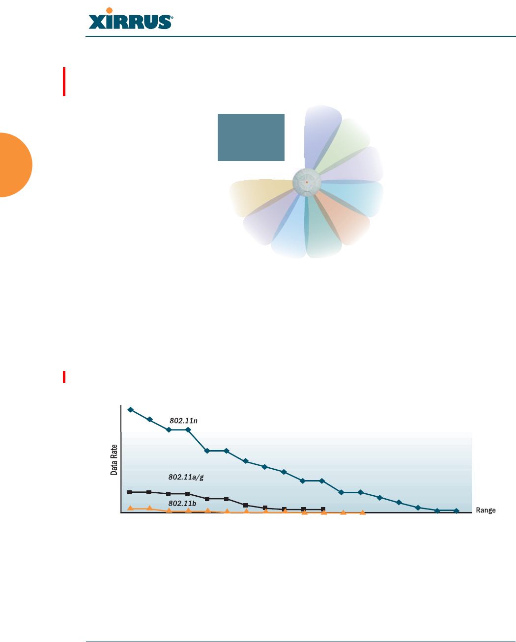
Wi-Fi Array
52 Installing the Wi-Fi Array
Custom Coverage
Where there are highly reflective objects in proximity to the Array, you can turn
off specific radios to avoid interference and feedback.
Figure 14. Custom Coverage
Capacity and Cell Sizes
Cell sizes should be estimated based on the number of users, the applications
being used (for example, data/video/voice), and the number of Arrays available
at the location. The capacity of a cell is defined as the minimum data rate desired
for each sector multiplied by the total number of sectors being used.
Figure 15. Connection Rate vs. Distance
Figure 15 shows relative connection rates for 802.11n vs. 802.11a/g and 802.11b,
and the effect of distance on the connection rates. Wireless environments can vary
greatly so the actual rates may be different depending on the specific network
deployment.
object
reflective

Wi-Fi Array
Installing the Wi-Fi Array 53
Fine Tuning Cell Sizes
Adjusting the transmit power allows you to fine tune cell sizes. There are four
standard sizes—Small, Medium, Large, or Max (the default is Max). There is also
an Auto setting that automatically determines the best cell size, and a Manual
setting that allows you to choose your power settings directly.
Figure 16. Transmit Power
Auto Cell Size is an automatic, self-tuning mechanism that balances cell size
between Arrays to guarantee coverage while limiting the RF energy that could
extend beyond the organizational boundary. Auto Cell uses communication
between Arrays to dynamically set radio power so that complete coverage is
provided to all areas, yet at the minimum power level required. This helps to
minimize potential interference with neighboring networks. Additionally, Arrays
running Auto Cell automatically detect and compensate for coverage gaps caused
by system interruptions. To enable the Auto Cell Size feature, go to “RF Power &
Sensitivity” on page 279. For a complete discussion of the Auto Cell size feature,
see the Xirrus Auto Cell Application Note in the Xirrus Library.
#The XS4 and XN4 have a smaller range than the larger Arrays.
Large
Medium
Small

Wi-Fi Array
54 Installing the Wi-Fi Array
If you are installing many units in proximity to each other, we recommend that
you use Auto Cell Size; otherwise, reduce the transmit power using manual
settings to avoid excessive interference with other Arrays or installed APs. See
also, “Coverage and Capacity Planning” on page 50.
Sharp Cell
This patented Xirrus RF management option automatically creates more
intelligently defined cells and improves performance by creating smaller, high-
throughput cells. By dynamically limiting each cell to a defined boundary (cell
size), the trailing edge bleed of RF energy is reduced, thus minimizing
interference between neighboring Wi-Fi Arrays or other Access Points. To enable
the Sharp Cell feature, go to “RF Power & Sensitivity” on page 279. For more
information about this feature, see the Xirrus Sharp Cell Application Note in the
Xirrus Library.
Roaming Considerations
Cells should overlap approximately 10 - 15% to accommodate client roaming.
Figure 17. Overlapping Cells
Allocating Channels
Because the Wi-Fi Array is a multi-channel device, allocating the best channels to
radios is important if peak performance is to be maintained.
ROAMING
10 - 15% overlap

Wi-Fi Array
Installing the Wi-Fi Array 55
Automatic Channel Selection
We recommend that you allow the Array to make intelligent channel allocation
decisions automatically. In the automatic mode, channels are allocated
dynamically, driven by changes in the environment. Auto Channel assignment is
performed by scanning the surrounding area for RF activity on all channels, then
automatically selecting and setting channels on the Array to the best channels
available. This function is typically executed when initially installing Arrays in a
new location and may optionally be configured to execute periodically to account
for changes in the RF environment over time. Auto Channel selection has
significant advantages, including:
z
Allows the Array to come up for the first time and not interfere with
existing equipment that may be already running, thereby limiting co-
channel interference.
z
More accurately tunes the RF characteristics of a Wi-Fi installation than
manual configuration since the radios themselves are scanning the
environment from their physical location.
z
May be configured to run periodically.
To set up the automatic channel selection feature, go to “Advanced RF Settings”
on page 275. For more information about this feature, see the Xirrus Auto Channel
Application Note in the Xirrus Library.
Manual Channel Selection
You can manually assign channels on a per radio basis, though manual selection
is not recommended (and not necessary).
#To avoid co-channel interference, do not select adjacent channels for radios
that are physically next to each other.

Wi-Fi Array
56 Installing the Wi-Fi Array
Figure 18. Allocating Channels Manually
See Also
Deployment Examples
Failover Planning
Installation Prerequisites
Maintain channel separation
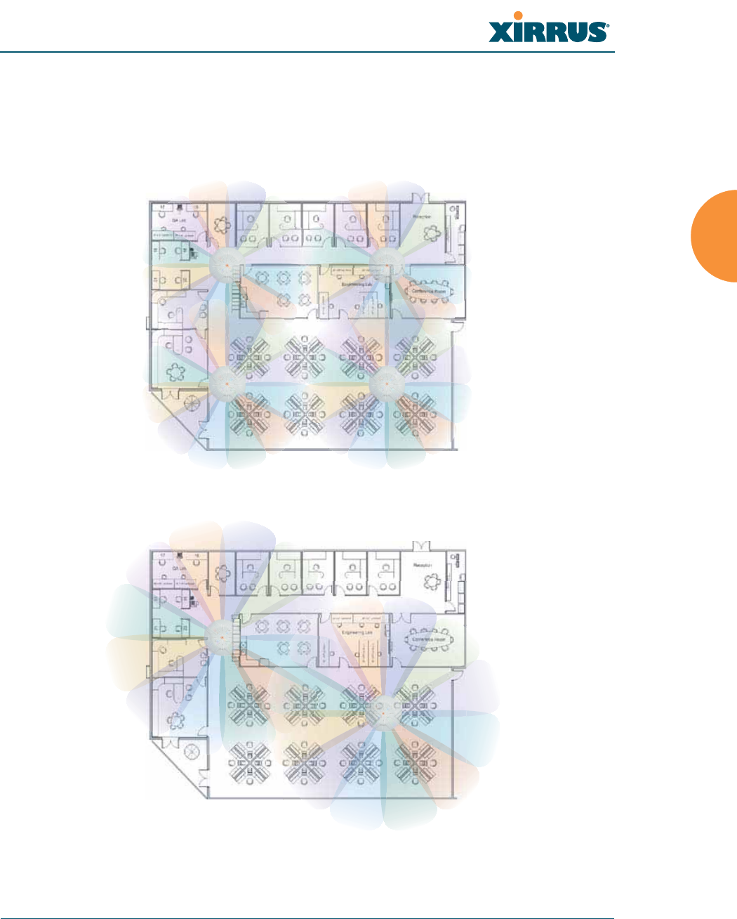
Wi-Fi Array
Installing the Wi-Fi Array 57
Deployment Examples
The following examples employ 802.11a cells, each offering minimum
throughputs of 54 Mbps, 36 Mbps, and 18 Mbps per sector respectively, and
assume a floor plan covering a total area of about 60,000 square feet (5574 sq m).
Figure 19. Deployment Scenario (54 Mbps)—Per Sector
Figure 20. Deployment Scenario (36 Mbps)—Per Sector
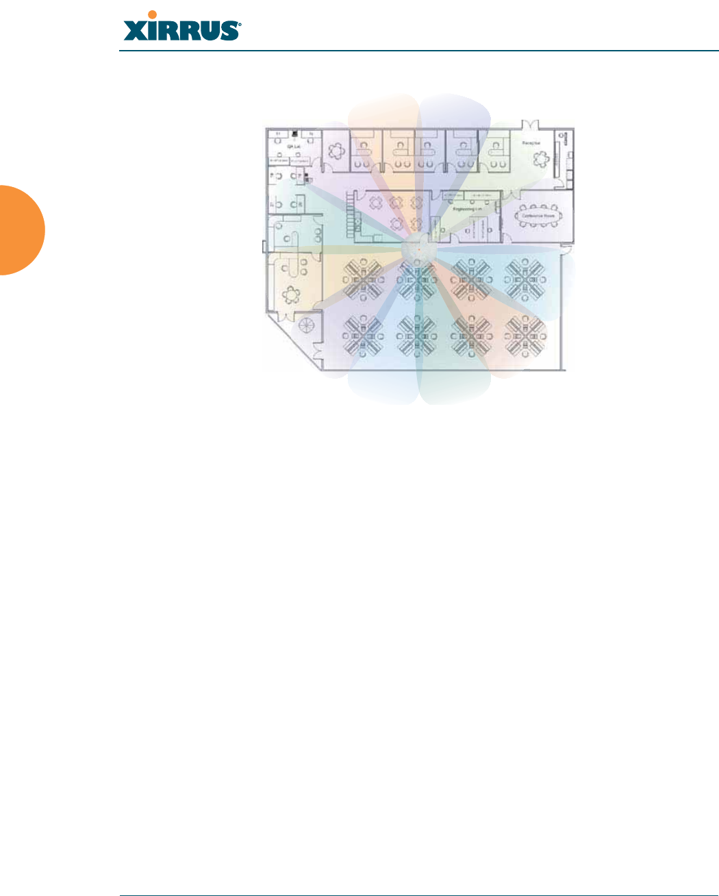
Wi-Fi Array
58 Installing the Wi-Fi Array
Figure 21. Deployment Scenario (18 Mbps)—Per Sector
See Also
Coverage and Capacity Planning
Failover Planning
Planning Your Installation

Wi-Fi Array
Installing the Wi-Fi Array 59
IEEE 802.11n Deployment Considerations
The Xirrus XN Arrays support IEEE 802.11n on all IAPs, in both 2.4 GHz and
5 GHz bands. Use of 802.11n offers significant benefits:
z
Higher data rates
z
Higher throughput
z
Supports more users
z
More robust connections
z
Increased coverage area
z
More secure connections—supports WPA2 (Wi-Fi Protected Access 2)
These benefits result in better support for a wide range of applications such as
voice and video, intensive usage such as CAD/CAM and backups, dense user
environments, and for manufacturing and warehousing environments.
The techniques that 802.11n uses to realize these performance improvements, and
the results that can be expected are discussed in:
z
“MIMO (Multiple-In Multiple-Out)” on page 60
z
“Multiple Data Streams—Spatial Multiplexing” on page 62
z
“Channel Bonding” on page 63
z
“Improved MAC Throughput” on page 64
z
“Short Guard Interval” on page 64
z
“Obtaining Higher Data Rates” on page 65
z
“802.11n Capacity” on page 66
Two very important techniques to consider are Channel Bonding and Multiple
Data Streams—Spatial Multiplexing because they contribute a large portion of
#IEEE 802.11n features are supported only on XN Array models, and this
section applies only to those Arrays.
#While 802.11n increases coverage area by almost doubling the reach, you
must consider the legacy wireless devices in your network. Wireless stations
connecting using 802.11a/b/g will still be subject to a reach of up to 100 feet,
depending on the environment.
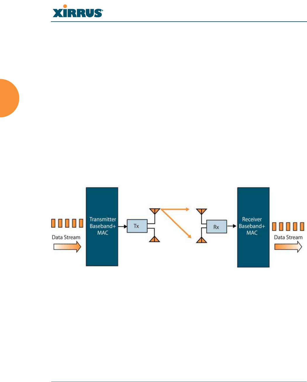
Wi-Fi Array
60 Installing the Wi-Fi Array
802.11n’s speed improvements and because they are optional and configurable, as
opposed to the parts of 802.11n that are fixed. While the settings for 802.11n IAPs
come pre-configured on the Array for robust performance in typical usage, you
should review the settings for your deployment, especially channel bonding. A
global setting is provided to enable or disable 802.11n mode. See “Global Settings
.11n” on page 273 to configure 802.11n operation.
MIMO (Multiple-In Multiple-Out)
MIMO (Multiple-In Multiple-Out) signal processing is one of the core
technologies of 802.11n. It mitigates interference and maintains broadband
performance even with weak signals.
Prior to 802.11n, a data stream was transmitted via one antenna. At the receiving
end, the antenna with the best signal was selected to receive data. (Figure 22)
Figure 22. Classic 802.11 Signal Transmission
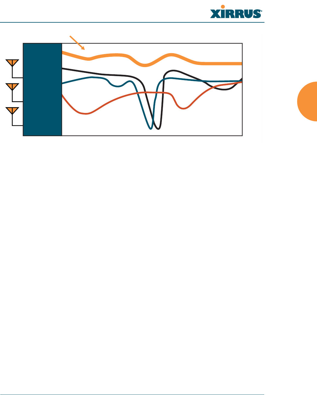
Wi-Fi Array
Installing the Wi-Fi Array 61
Figure 23. MIMO Signal Processing
MIMO signal processing uses multiple antennas to send and receive data. It takes
advantage of multipath reflections to improve signal coherence and greatly
increase receiver sensitivity (Figure 23). Multipath signals were considered to be
interference by 802.11a/b/g radios, and degraded performance. In 802.11n, these
signals are used to enhance performance. This extra sensitivity can be used for
greater range or higher data rates. The enhanced signal is the processed sum of
individual antennas. Signal processing eliminates nulls and fading that any one
antenna would see. MIMO signal processing is sophisticated enough to discern
multiple spatial streams (see Multiple Data Streams—Spatial Multiplexing). There
are no settings to configure for MIMO.
Frequency Across Subcarriers
Attenuation
Antenna 1 Signal
MIMO Processed Signal
Antenna 2 Signal
Antenna 3 Signal
Receiver
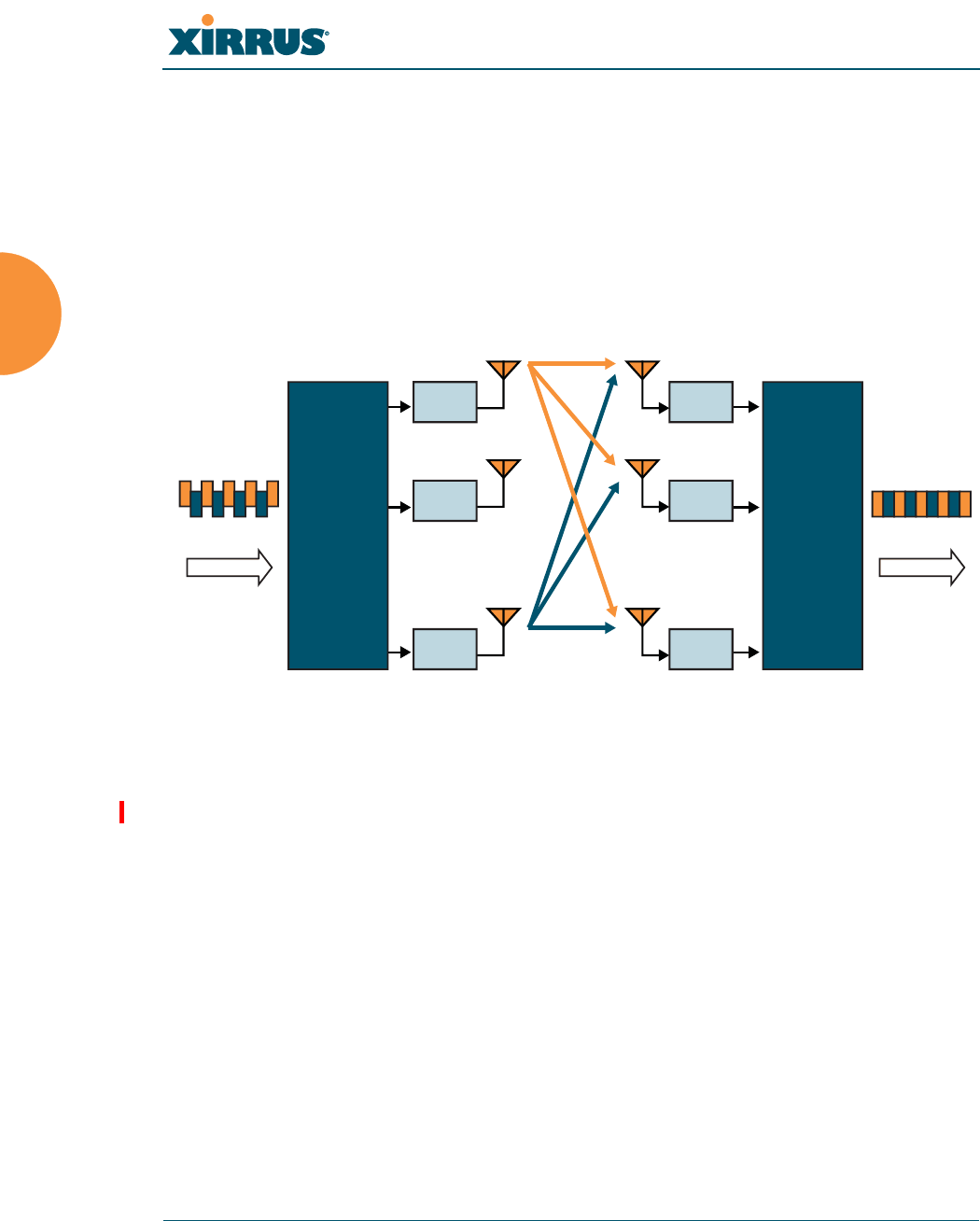
Wi-Fi Array
62 Installing the Wi-Fi Array
Multiple Data Streams—Spatial Multiplexing
Spatial Multiplexing transmits completely separate data streams on different
antennas (in the same channel) that are recombined to produce new 802.11n data
rates. Higher data rates are achieved by splitting the original data stream into
separate data streams. Each separate stream is transmitted on a different antenna
(using its own RF chain). MIMO signal processing at the receiver can detect and
recover each stream. Streams are then recombined, yielding higher data rates.
Figure 24. Spatial Multiplexing
Spatial multiplexing can double, triple, or quadruple the date rate, depending on
the number of transmit antennas used. The Array uses three chains for
transmitting and receiving.
%
Rx 1
Rx 2
Rx
M
%
Transmitter
Data Stream Data Stream
Receiver
Tx 1
Tx 2
Tx
N
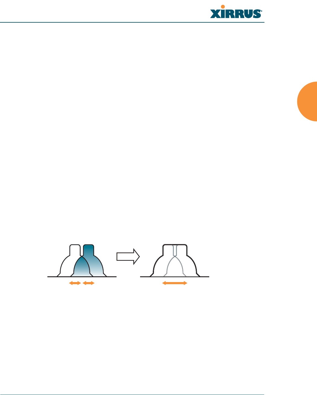
Wi-Fi Array
Installing the Wi-Fi Array 63
Channel Bonding
Channel bonding increases data rates by combining two adjacent 20 MHz
channels into one 40 MHz channel. This increases the data rate to slightly more
than double.
A bonded 40 MHz channel is specified in terms of the Primary channel and the
adjacent channel to Bond. The Bond channel is represented by +1 to use the
channel above the Primary channel, or -1 to use the channel below. In the example
shown, Channel 40 is the Primary channel and it is bonded to Channel 36, the
channel below it, by specifying -1. Be aware that Channel Bonding can make
channel planning more difficult, since you are using two channels for an IAP. We
recommend the use of the 5 GHz band, since it has many more channels than the
2.4 GHz band, and thus more channels are available for bonding.
The Array provides an Automatic Channel Bonding setting that will
automatically select the best channel for bonding on each IAP. If you enable this
option, you may select whether bonding will be dynamic (the bonded channel
changes in response to environmental conditions) or static (the bonded channel
will not be changed. See “Global Settings .11n” on page 273. To configure channel
bonding manually, on a per-IAP basis, see “IAP Settings” on page 255.
Figure 25. Channel Bonding
Ch# Ch#
40
20 MHz 20 MHz
36
40 MHz
(40, -1)
Standard 802.11 channels are
effectively 20MHz wide.
Channel bonding combines
two adjacent 20MHz channels
into a single 40MHz channel
providing increased throughput.
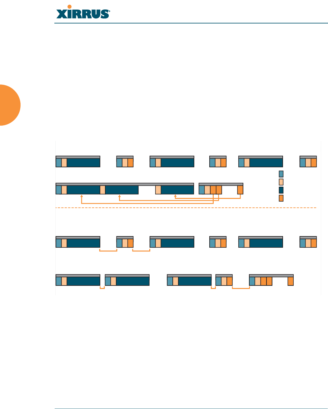
Wi-Fi Array
64 Installing the Wi-Fi Array
Improved MAC Throughput
These changes make 802.11n transmission of MAC frames 40% more efficient than
legacy transmission:
z
MAC data frames are combined and given a single PHY header.
z
Implicit Block ACK acknowledges all data frames within a combined
frame.
z
Spacing between frames is reduced.
Figure 26. MAC Throughput Improvements
Short Guard Interval
This option reduces the wait time between signals that are being sent out over the
air. The guard interval provides immunity to propagation delays and reflections,
and is normally 800 ns (long). By using a short guard interval (400 ns), the data
rate is increased by approximately 11%. The short interval may be used in many
environments (especially indoors). If the short guard interval is used in an
N
ACK Frame
N
Data Frame
2
Data Frame
PHY Header
MAC Header
Data Frame Payload
ACK Frame Payload
Legacy Operation
High Throughput Operation
Data Frame
sss
sss sss
1
Data Frame Block ACK Frame
1122NN
ACK Frame
1 2
ACK Frame
NN
Data Frame
SIFS
SIFS
SIFS
RIFS RIFS
Legacy Operation
High Throughput Operation
Data Frame ACK Frame
sss
ssssss
1
1 2
Data Frame Data Frame Data Frame
Block ACK
Request
Frame
Block ACK
Response
Frame
12 N
1 2 2
2
Data Frame ACK Frame
N
ACK Frame
RIFS Usage (Reduced Inter-Frame Spacing)
Frame Aggregation
Wi-Fi Array
Installing the Wi-Fi Array 65
inappropriate environment, the signal quality will suffer and throughput will
decrease. See “Global Settings .11n” on page 273 to configure the guard interval.
Obtaining Higher Data Rates
The data rate increase obtained by using 802.11n on an Array is incremental,
based on the technologies that are applied and the options that you select:
z
Higher encoding rates (Mandatory in 802.11n)
z
Spatial Streams (Mandatory, but multiplier varies directly with number of
streams selected.)
z
Channel Bonding (Mandatory in 802.11n, apply multiplier to IAP if it is
bonded.)
z
Short Guard Interval (Optional)
See Figure 27 to compute your 802.11n data rate increase for an IAP. Apply this
increase to the 802.11 a, b or g data rates selected for the Array.
Figure 27. Computing 802.11n Data Rates
Optionally
Multiply By 2.077
to Bond
Two 20MHz
Channels
Optionally
Multiply by 1.11 for
Shorter Guard Interval
to Increase
Symbol Rate
Optionally
Multiply by 2, 3, 4
for the Number of
Additional
Spatial Streams
Choose New Base
Encoding + Modulation
BPSK (6.5)
QPSK (13, 19.5)
QAM-16 (26, 39)
QAM-64 (58.5, 65)
New 11n
Data Rate
xxx =
Expected First Generation Device Data Rates
Expected 802.11n Data Rates
802.11a 802.11g
Rates
6
9
12
18
24
36
48
54
11n Mandatory
Data Rates
6.5
13
19.5
26
39
52
58.5
65
With Channel
Bonding (40MHz)
13.5
27
40.5
54
81
108
121.5
135
With Short
Guard Interval
15
30
45
60
90
120
135
150
Two Spatial
Streams
13
26
39
52
78
104
117
130
With Channel
Bonding (40MHz)
27
54
81
108
162
216
243
270
With Short
Guard Interval
30
60
90
120
180
240
270
300
One Spatial Stream Two Spatial Streams
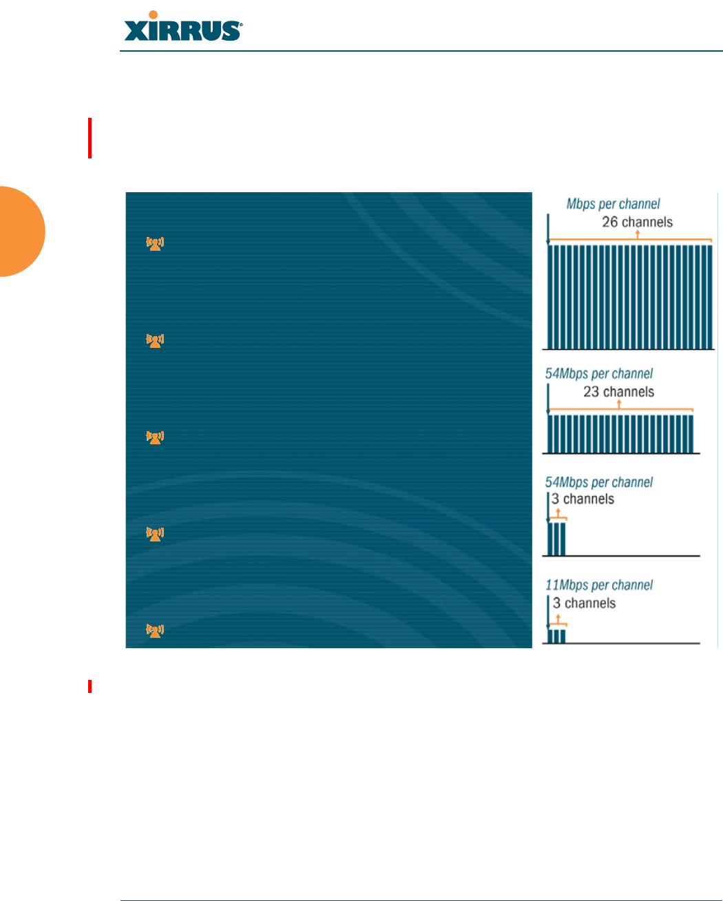
Wi-Fi Array
66 Installing the Wi-Fi Array
802.11n Capacity
802.11n offers major increases in capacity over previous 802.11 standards, as
shown in Figure 28. Note that this chart shows figures for 802.11n (with one
spatial stream and channel bonding).
Figure 28. 802.11n Increases Capacity
802.11a/n Capacity
23 channels * 150Mbps = 3.4Gbps
802.11a Capacity
23 channels * 54Mbps = 1.2 Gbps
802.11g/n Capacity
3 channels * 150Mbps = 450 Mbps
802.11g Capacity
3 channels * 54Mbps = 162 Mbps
802.11b Capacity
3 channels * 11Mbps = 33 Mbps
802.11a/n Capacity
23 channels * 150Mbps = 3.4Gbps
802.11a Capacity
23 channels * 54Mbps = 1.2 Gbps
802.11g/n Capacity
3 channels * 150Mbps = 450 Mbps
802.11g Capacity
3 channels * 54Mbps = 162 Mbps
802.11b Capacity
3 channels * 11Mbps = 33 Mbps
150
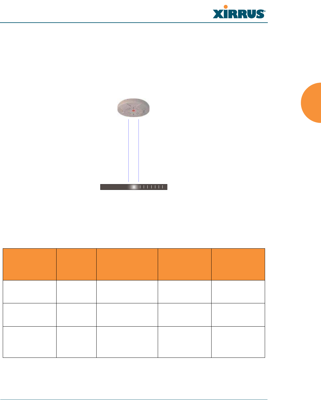
Wi-Fi Array
Installing the Wi-Fi Array 67
Failover Planning
This section discusses failover protection at the unit and port levels.
Port Failover Protection
To ensure that service is continued in the event of a port failure, you can utilize
the Gigabit 1 and Gigabit 2 ports simultaneously.
Figure 29. Port Failover Protection
In addition, the Array has full failover protection between the Gigabit 1 and
Gigabit 2 Ethernet ports (see following table).
The Wi-Fi Array Gigabit Ethernet ports actually support a number of modes:
z
802.3ad Link Aggregation
Interface Bridges
Data?
Bridges
Management
Traffic?
Fails Over To: IP address
Fast Ethernet No Yes None DHCP or
static
Gigabit 1 Yes Yes Gigabit 2 DHCP or
static
Gigabit 2 Yes Yes Gigabit 1 Assumes the
IP address of
Gigabit 1
Ethernet switch
Multiple port connections
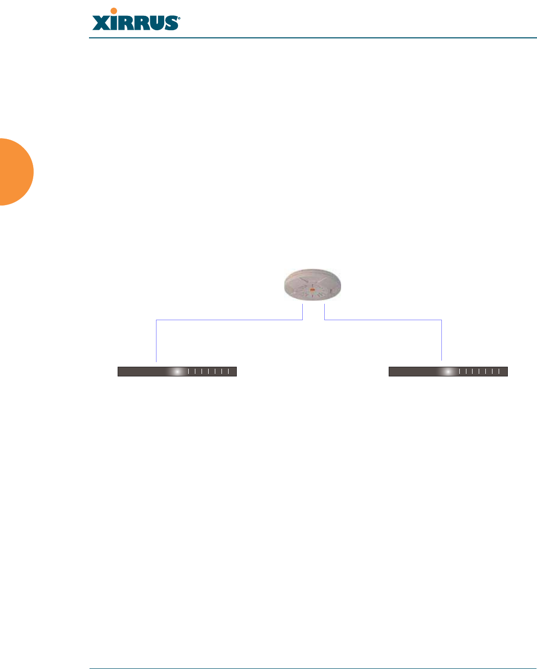
Wi-Fi Array
68 Installing the Wi-Fi Array
z
Load Balancing
z
Broadcast
z
Link Backup
z
Bridged
z
Mirrored
For more details on Gigabit port modes and their configuration, please see
“Network Interface Ports” on page 184.
Switch Failover Protection
To ensure that service is continued in the event of a switch failure, you can
connect Arrays to more than one Ethernet switch (not a hub).
Figure 30. Switch Failover Protection
See Also
Coverage and Capacity Planning
Deployment Examples
Installation Prerequisites
Network Management Planning
Planning Your Installation
Power Planning
Security Planning
#Gigabit Ethernet connections must be on the same subnet.
Ethernet switch Backup switch
Ethernet connections

Wi-Fi Array
Installing the Wi-Fi Array 69
Power Planning
All XN Series Array models and XS16/12/8/4 Arrays support Power over
Gigabit Ethernet (PoGE) with an integrated splitter. AC power is also supported
on all XN Arrays and some versions of the XS8, XS12, and XS16.
This section discusses the AC and PoGE power options.
AC Power
The AC power option requires a direct connection between the Array and a
dedicated AC power outlet. The power cord is provided with the unit.
Power over Gigabit Ethernet
To deliver power to the Array, you may use the optional XP1 or XP8 Power over
Gigabit Ethernet (PoGE) modules. They provide power over Cat 5e or Cat 6 cables
to the Array without running power cables—see Figure 5 on page 13.
Specific models of the Array are compatible with specific PoGE modules. For
details, please see “Power over Gigabit Ethernet Compatibility Matrix” on
page 414.
See Also
Coverage and Capacity Planning
Deployment Examples
Failover Planning
Network Management Planning
Security Planning
#When using Cat 5e or Cat 6 cable, power can be provided up to a distance of
100m.

Wi-Fi Array
70 Installing the Wi-Fi Array
Security Planning
This section offers some useful guidelines for defining your preferred encryption
and authentication method. For additional information, see “Understanding
Security” on page 210 and the Security section of “Frequently Asked Questions”
on page 398.
Wireless Encryption
Encryption ensures that no user can decipher another user’s data transmitted
over the airwaves. There are three encryption options available to you, including:
z
WEP-40bit or WEP-128bit
Because WEP is vulnerable to cracks, we recommend that you only use
this for legacy devices that cannot support a stronger encryption type.
z
Wi-Fi Protected Access (WPA)
This is much more secure than WEP and uses TKIP for encryption.
z
Wi-Fi Protected Access (WPA2) with AES
This is government-grade encryption—available on most new client
adapters—and uses the AES–CCM encryption mode (Advanced
Encryption Standard–Counter Mode).
Authentication
Authentication ensures users are who they say they are, and occurs when users
attempt to join the wireless network and periodically thereafter. The following
authentication methods are available with the Wi-Fi Array:
z
RADIUS 802.1x
802.1x uses a remote RADIUS server to authenticate large numbers of
clients, and can handle different authentication methods (EAP-TLS, EAP-
TTLS, EAP-PEAP, and EAP-LEAP Passthrough). Administrators may
also be authenticated via RADIUS when preferred, or to meet particular
security standards.
z
Xirrus Internal RADIUS server
Recommended for smaller numbers of users (about 100 or less). Supports
EAP-PEAP only

Wi-Fi Array
Installing the Wi-Fi Array 71
z
Pre-Shared Key
Uses a pass-phrase or key that is manually distributed to all authorized
users. The same passphrase is given to client devices and entered into
each Array.
z
MAC Access Control Lists (ACLs)
MAC access control lists provide a list of client adapter MAC addresses
that are allowed or denied access to the wireless network, and can be
used in addition to any of the above authentication methods. ACLs are
good for embedded devices, like printers and bar-code scanners (though
MAC addresses can be spoofed). The Wi-Fi Array supports 1,000 ACL
entries.
Meeting PCI DSS Standards
The Payment Card Industry (PCI) Data Security Standard (DSS) was developed
by major credit card companies. It lays out a set of requirements that must be met
in order to provide adequate security for sensitive data. The the Wi-Fi Array may
be configured to satisfy PCI DSS standards. For details, please see Appendix D:
Implementing PCI DSS.
Meeting FIPS Standards
The Federal Information Processing Standard (FIPS) Publication 140-2 establishes
a computer security standard used to accredit cryptographic modules. The
standard is a joint effort by the U.S. and Canadian governments. To implement
Level 2 security requirements of FIPS Level 2 on the Wi-Fi Array, see Appendix E:
Implementing FIPS Security.
See Also
Failover Planning
Network Management Planning
Power Planning
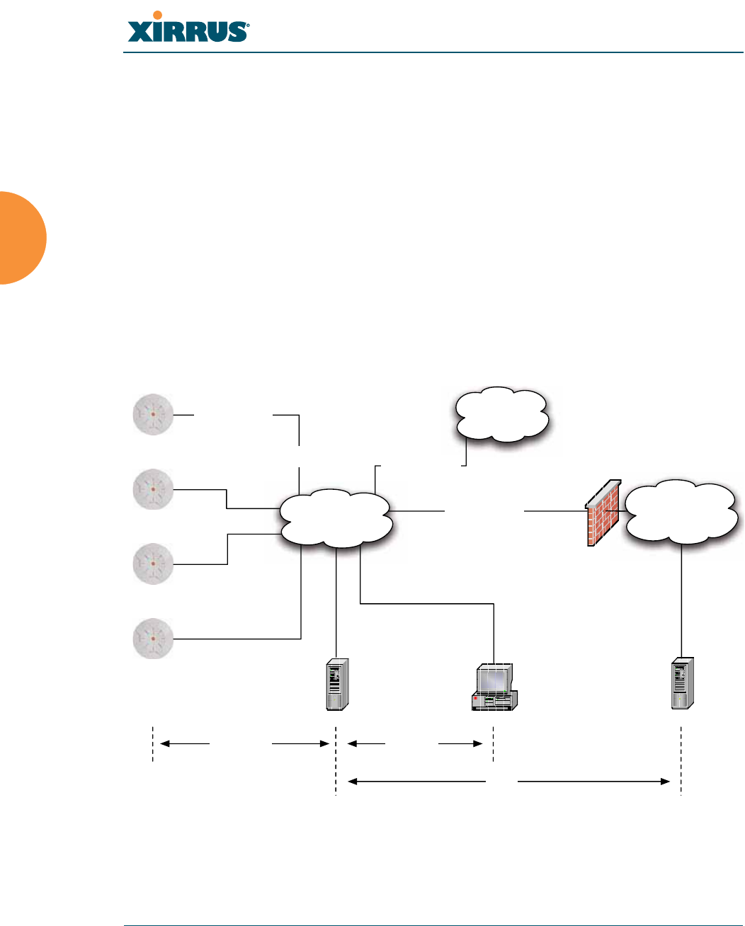
Wi-Fi Array
72 Installing the Wi-Fi Array
Port Requirements
A number of ports are used by various Array features and by the Xirrus
Management System (XMS). The Port Requirements table on page 73 lists ports
and the features that require them (XMS port requirements are included in the
table for your convenience). If you are using a feature, please make sure that the
ports that it requires are not blocked by firewalls or other policies, and that they
do not conflict with any other port assignments.
As an example, XMS port requirements are illustrated in Figure 31. XMS requires
ports 161, 162, and 443 to be passed between Arrays and the XMS server.
Similarly, ports 9090 and 9091 are required for communication between the XMS
server and XMS clients, and port 25 is typically used by the XMS server to access
an SMTP server to send email notifications.
Figure 31. Port Requirements for XMS
Firewall
XMS Server XMS Client*
L2 Switching
Infrastructure
SMTP Server*
Internal
Resources
External Network /
Internet
Ports:
9090, 9091
Ports:
161, 162, 443
SSID Trafc on
VLANs A, B, etc.
Management over
Native VLAN
Trafc from Arrays
VLAN B
Trafc from Arrays
VLAN A
Trunked 802.1q
VLAN Connection
Ports:
25
* XMS Client and SMTP Server may be internal or external resources.
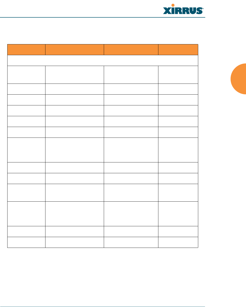
Wi-Fi Array
Installing the Wi-Fi Array 73
The following table lists port requirements for the Array and for XMS, how they
are used, and whether they may be changed.
Port Application Peer Configurable
Array
20 tcp
21 udp FTP Client Yes
22 tcp SSH Client Yes
23 tcp Telnet Client Yes
25 tcp SMTP Mail Server No
69 tcp TFTP TFTP Server No
161 tcp/udp SNMP XMS Server No
162 tcp/udp
SNMP Traphost Note -
Up to four Traphosts
may be configured.
XMS Server
Yes - but
required by
XMS
443 tcp HTTPS (WMI,WPR) Client Yes
514 udp Syslog Syslog Server No
1812, 1645
udp
RADIUS (some
servers use 1645) RADIUS Server Yes
1813, 1646
udp
RADIUS Accounting
(some servers still use
1646)
RADIUS Accounting
Server Yes
2055 udp Netflow Client Yes
5000 tcp Virtual Tunnel VTUN Server Yes
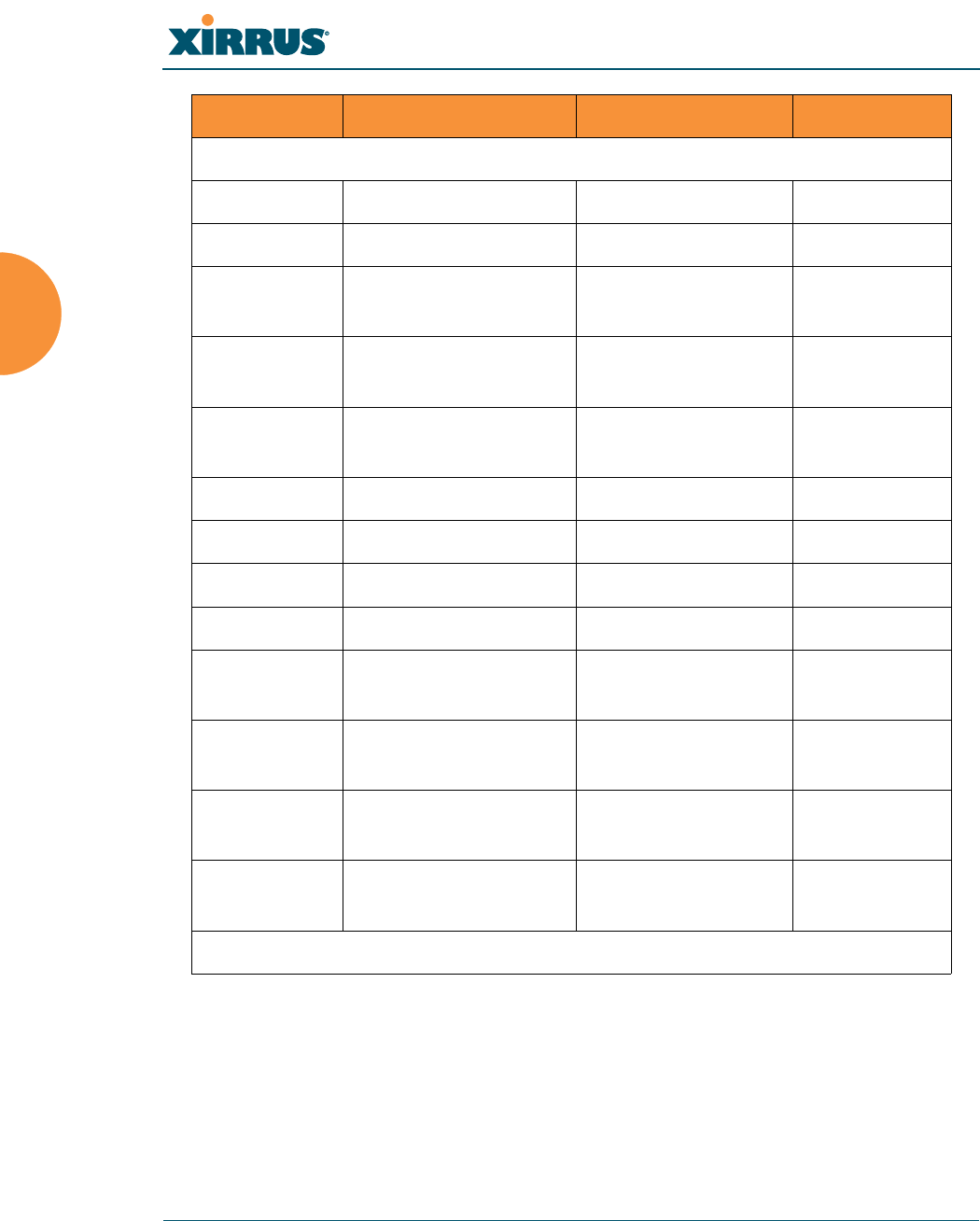
Wi-Fi Array
74 Installing the Wi-Fi Array
See Also
Management Control
External Radius
Services
VLAN Management
XMS
25 tcp SMTP Mail Server Yes
161 udp SNMP Arrays No
162 udp SNMP Traphost 1 Arrays Via XMS
config file
443 tcp HTTPS Arrays No
514 udp Resident Syslog
server Internal* Via XMS
config file
1099 tcp RMI Registry Internal* No
2000 tcp XMS Back-end Server Internal* No
3306 tcp MySQL Database Internal* No
8001 tcp Status Viewer Internal* No
8007 tcp Tomcat Shutdown Internal* During
installation
8009 tcp Web Container Internal* During
installation
9090 tcp XMS Webserver XMS client During
installation
9091 tcp XMS Client Server XMS client Via XMS
config file
* Internal to XMS Server, no ports need to be unblocked on other network devices
Port Application Peer Configurable

Wi-Fi Array
Installing the Wi-Fi Array 75
Network Management Planning
Network management can be performed using any of the following methods:
z
Command Line Interface, using an SSH (Secure Shell) utility, like PuTTY.
The utility must be set up to use SSH-2, since the Array will only allow
SSH-2 connections.
z
Web-based management, using the Array’s embedded Web Management
Interface (WMI). This method provides configuration and basic
monitoring tools, and is good for small deployments (one or two units).
z
Centralized Web-based management, using the optional Xirrus
Management System (XMS), which can be run on a dedicated Xirrus
appliance (XM-3300) or your own server. The XMS is used for managing
large Wi-Fi Array deployments from a centralized Web-based interface
and offers the following features:
Globally manage large numbers of Arrays (up to 500)
Seamless view of the entire wireless network
Easily configure large numbers of Arrays
Rogue AP monitoring
Easily manage system-wide firmware updates
Monitor performance and trends
Aggregation of alerts and alarms
See Also
Failover Planning
Power Planning
Security Planning
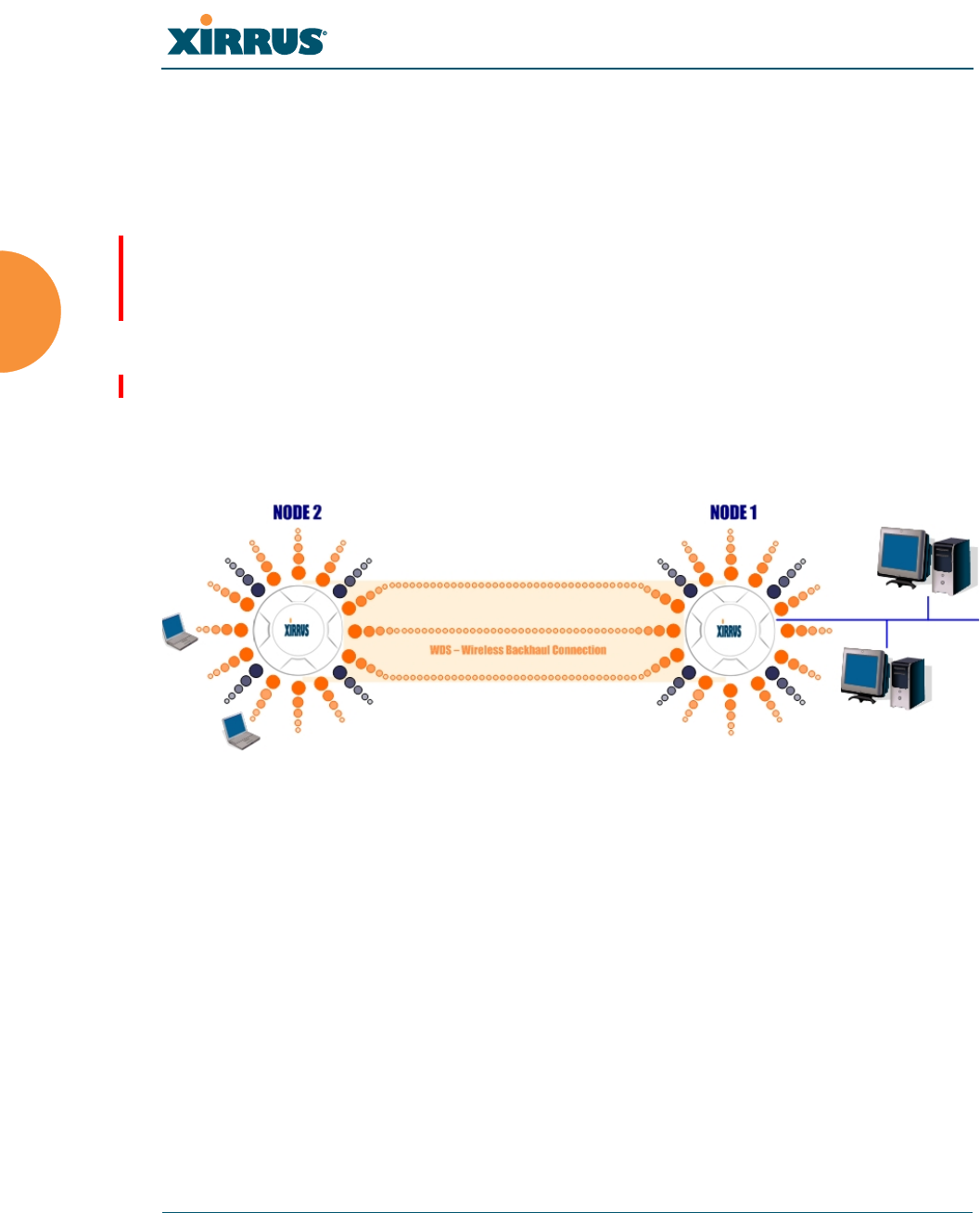
Wi-Fi Array
76 Installing the Wi-Fi Array
WDS Planning
WDS (Wireless Distribution System) creates wireless backhauls between arrays,
allowing your wireless network to be expanded using multiple Arrays without
the need for a wired backbone to link them (see Figure 32). WDS features include:
z
One to three IAPs may be used to form a single WDS link, yielding up to
900 Mbps bandwidth per link (up to 162 Mbps for XS model Arrays). Up
to three different WDS links may be created on a single Array.
z
Automatic IAP Load Balancing
z
If desired, you may allow clients to associate to a BSS on the same radio
interface used for a WDS Host Link. This will take bandwidth from the
WDS link.
Figure 32. WDS Link
z
Multiple links per Array allow you to configure multi-hop connections.
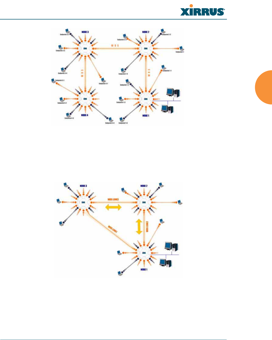
Wi-Fi Array
Installing the Wi-Fi Array 77
Figure 33. A Multiple Hop WDS Connection
z
Multiple WDS links can provide link redundancy (failover capability - see
Figure 34). A network protocol (Spanning Tree Protocol—STP) prevents
Arrays from forming network loops.
Figure 34. WDS Failover Protection

Wi-Fi Array
78 Installing the Wi-Fi Array
WDS links have a Host/Client relationship similar to the usual IAP/station
pattern for Arrays:
z
A WDS Client Link associates/authenticates to a host (target) Array in the
same way that a station associates to an IAP. The client side of the link
must be configured with the root MAC address of the target (host) Array.
z
A WDS Host Link acts like an IAP by allowing one WDS Client Link to
associate to it. An Array may have both client and host links.
WDS configuration is performed only on the client-side Array. See “WDS” on
page 285. Note that both Arrays must be configured with the same SSID name.

Wi-Fi Array
Installing the Wi-Fi Array 79
Common Deployment Options
The following table lists some typical and recommended deployment options for
a number of the features that have been discussed in this chapter.
See Also
Coverage and Capacity Planning
Deployment Examples
Network Management Planning
Planning Your Installation
Power Planning
Security Planning
Function
Number of Wi-Fi Arrays
One or Two Three or More
Power AC (some Array models)
Power over Gigabit
Ethernet
AC (some Array models)
Power over Gigabit Ethernet
UPS backup
(recommended)
Failover Recommended Highly recommended
VLANs Optional Optional use,
Can be used to put all APs
on one VLAN or map to
existing VLAN scheme
Encryption WPA2 with AES
(recommended)
PSK or 802.1x
WPA2 with AES
(recommended)
802.1x keying
Authentication Internal RADIUS server
EAP-PEAP
Pre-Shared Key
External RADIUS server
Management Internal WMI
Internal CLI (via SSHv2)
XMS (SNMP)
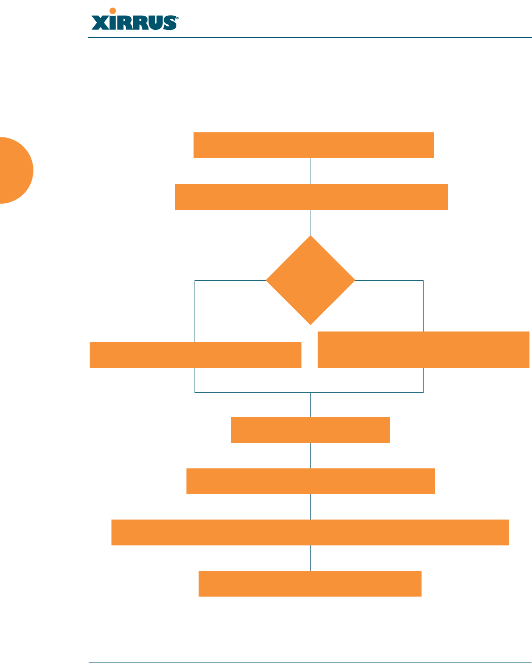
Wi-Fi Array
80 Installing the Wi-Fi Array
Installation Workflow
This workflow illustrates the steps that are required to install and configure your
Wi-Fi Array successfully. Review this flowchart before attempting to install the
unit on a customer’s network.
Figure 35. Installation Workflow
Determine the number of Arrays needed
Choose the location(s) for your Wi-Fi Arrays
AC PoGE
Install the mounting plate
Connect the cables and turn on the power
Verify that the Ethernet link and radio LEDs are functioning correctly
Perform the Express Setup procedure
Run AC power and Ethernet cables Run Ethernet cables (<100m total
AC or PoGE?
idistance from switch)

Wi-Fi Array
Installing the Wi-Fi Array 81
See Also
Coverage and Capacity Planning
Deployment Examples
Common Deployment Options
Failover Planning
Installation Prerequisites
Planning Your Installation
Power Planning
Wi-Fi Array Product Overview
Product Specifications—XN16, XN12, and XN8
Product Specifications—XS16/XS-3900, XS12, and XS8/XS-3700
Product Specifications—XS4/XS-3500
Security Planning
Unpacking the Wi-Fi Array
When you unpack your Wi-Fi Array, you will find the following items in the
carton:
Item Quantity
Xirrus Wi-Fi Array 1
AC power cord (for AC-equipped models) 1
Console cable 1
Mounting plate 1
Mounting screws 4
Tile grid mounting clamps 4
Clamp nuts 4
Mounting template 1
Wi-Fi Array
82 Installing the Wi-Fi Array
See Also
Installation Prerequisites
Installation Workflow
CD-ROM containing:
This User’s Guide in PDF format
End User License Agreement (EULA)
README file
1
Quick Install Guide 1
Registration Card 1
Item Quantity
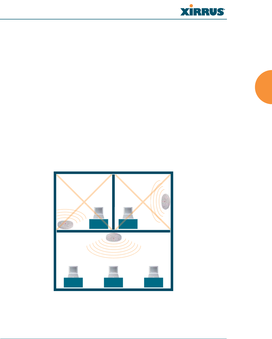
Wi-Fi Array
Installing the Wi-Fi Array 83
Installing Your Wi-Fi Array
This section provides instructions for completing a physical installation of your
Xirrus Wi-Fi Array.
Choosing a Location
Based on coverage, capacity and deployment examples previously discussed,
choose a location for the Array that will provide the best results for your needs.
The Wi-Fi Array was designed to be mounted on a ceiling where the unit is
unobtrusive and wireless transmissions can travel unimpeded throughout open
plan areas.
You also have the option of mounting the Array on a wall, using the optional wall
mount assembly kit. For wall mount instructions, go to “Mounting Array on a
Wall (All models except 4-port Arrays)” on page 96.
Choose a location that is central to your users (see the following diagram for
correct placement.
Figure 36. Array Placement
WR
ONG
CORRECT
R
ORRE
R
ORREC
WR
ONG
G
G
O
ON
R
O
R
ON
ON
R
O
R
ON

Wi-Fi Array
84 Installing the Wi-Fi Array
Wiring Considerations
If you are using the Xirrus Power over Gigabit Ethernet modules (PoGE) to
distribute power, see “Power over Gigabit Ethernet (PoGE) (Optional)” on
page 13. If you prefer to use AC power and you have an Array that supports AC,
an AC power outlet must be available to the Array.
Once you have determined the best location for your Wi-Fi Array, you must run
cables to the location for the following services:
Power
One of the following options:
z
No power cable is required if using PoGE modules.
z
Dedicated AC power if PoGE is not in use. A UL-approved cord
is shipped with all AC-equipped Arrays. You must use a UL-
approved cord if using AC power.
Network
z
Gigabit 1—If using PoGE modules, the total of all Cat 5e or Cat 6
cable segments from the Gigabit Ethernet switch to the Array
must be less than 100m long. The Array must be connected to
PoGE networks without routing cabling to the outside plant, to
ensure that cabling is not exposed to lightning strikes or possible
high voltage crossover.
z
Gigabit 2 (optional, not available on the four-port Arrays)
z
Fast Ethernet (optional, not available on the four-port Arrays)
z
Serial cable (optional) — cable lengths up to 25’ per the RS-232
specification.

Wi-Fi Array
Installing the Wi-Fi Array 85
Important Notes About Network Connections
Read the following notes before making any network connections.
See Also
Failover Planning
Installation Prerequisites
Installation Workflow
Mounting the Wi-Fi Array on a Wall (XS4 and XS-3500)
Mounting Array on a Wall (All models except 4-port Arrays)
Mounting the Array on a Ceiling
Power over Gigabit Ethernet (PoGE) (Optional)
Unpacking the Wi-Fi Array
#When the unit’s IP address is unknown or a network connection has not
been established, the serial cable is used for connecting directly with the
Command Line Interface (CLI) via HyperTerminal. When a network
connection is established, the Array can be managed from any of the
available network connections, either Fast Ethernet, Gigabit 1 or Gigabit 2.
!The Array’s Ethernet ports should be plugged into an Ethernet switch, not an
Ethernet hub—if a hub is used, we recommend that you connect only one
Ethernet port.
!The Gigabit1 Ethernet interface is the primary port for both data and
management traffic. If a single Ethernet connection is used, it must be
connected to the Gigabit1 Ethernet interface. See also, “Port Failover
Protection” on page 67.
The 10/100 Ethernet Port may be used for managing the Array out of band
from the Gigabit Ethernet ports. The 10/100 port will route only management
traffic, using a static route that may be configured for this interface. See
“interface” on page 336.
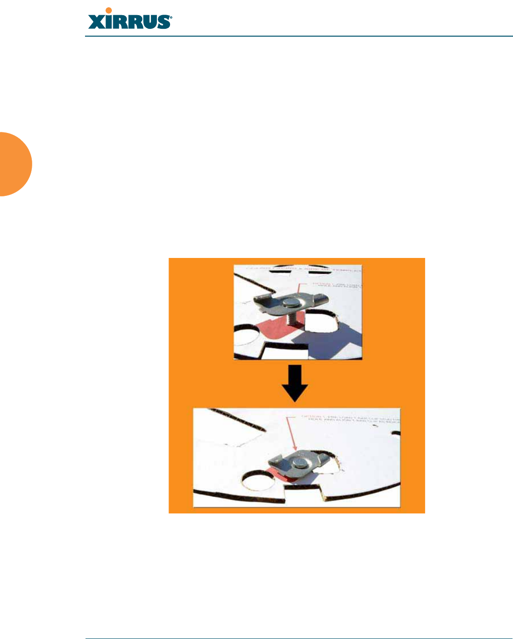
Wi-Fi Array
86 Installing the Wi-Fi Array
Mounting the Array on a Ceiling
Most offices have drop-down acoustical ceiling tiles set into a standard grid. The
Wi-Fi Array has been designed to enable mounting to a tiled ceiling via a
mounting plate and clamps that attach to the grid. Once the mounting plate is
attached, the Array simply rotates onto the plate (similar to a smoke detector).
Once the unit is mounted it can be removed and re-attached easily, without the
need for tools or modifications to the original installation.
This section assumes that you are mounting the Array to a tiled ceiling. If your
ceiling is not tiled, the mounting plate can be attached directly to the ceiling with
the screws and anchors provided (without using the tile grid mounting clamps).
Attaching the T-Bar Clips to the Template
.
Figure 37. Attaching the T-Bar Clips to the Template
The T-bar clips create four mounting points on the ceiling tile grid for the Array
mounting plate. Use the mounting template (provided) to find the correct location
for all four clamps by pre-loading the 4 T-bar clips through the holes in the
mounting template. Twist the clips until they are correctly aligned with the
markings on the template.
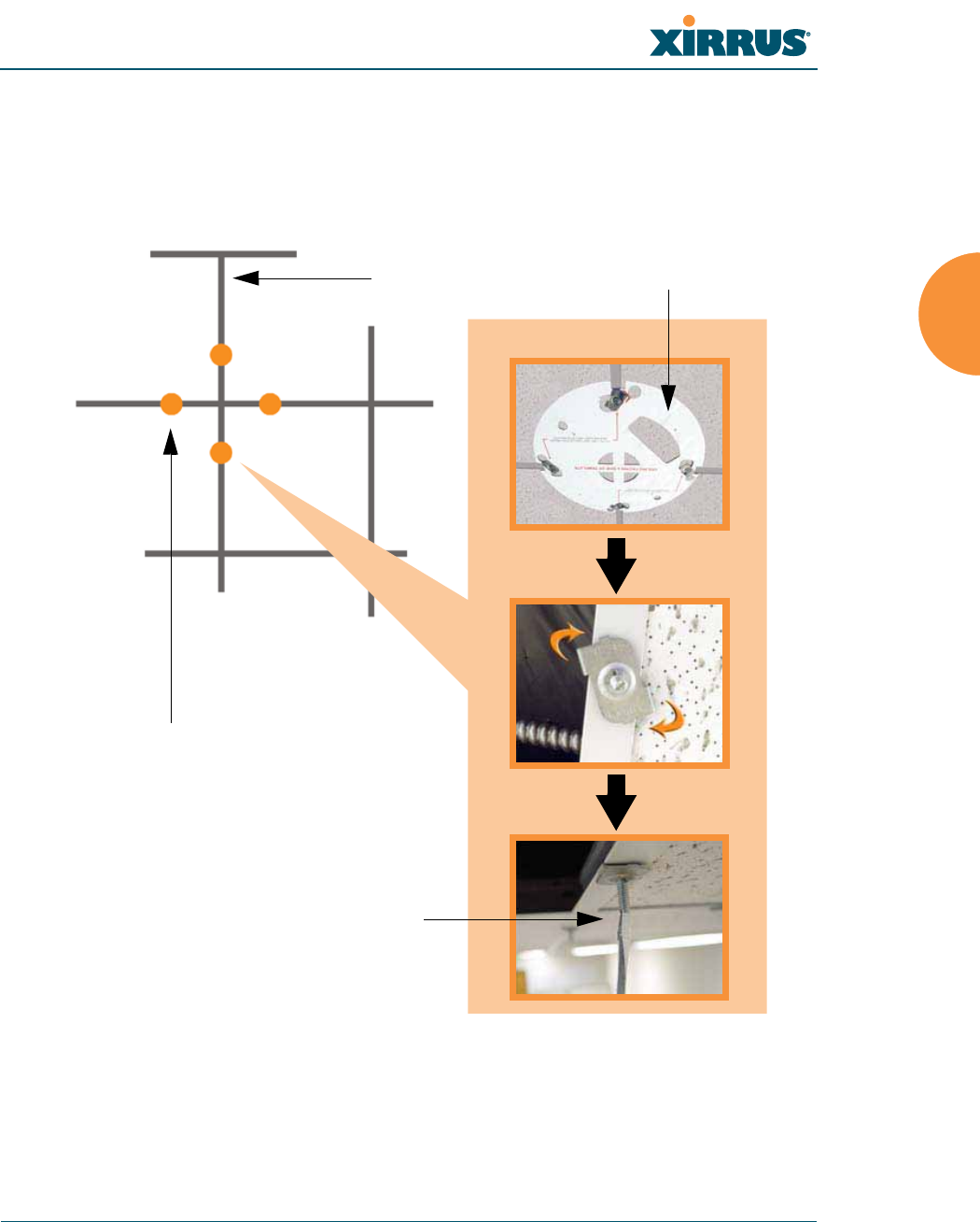
Wi-Fi Array
Installing the Wi-Fi Array 87
Secure the T-Bar Clips to the Ceiling Support Grid
The mounting template should be oriented so that the Array’s abg(n)2 omni-
directional monitoring IAP (radio) is pointing in the direction of the least required
wireless signal coverage—for example, a nearby exterior wall or entrance.
Figure 38. Attaching the T-Bar Clips to the Ceiling Grid
Use the mounting template to find the correct location for all four T-bar clips, then
twist the clips onto the metal ceiling support grid (Figure 38). Tighten the screw
posts to 10-12 lbf.ft (1.38-1.66 kgf.m). Do not overtighten the screw posts. Disengage
the template from the four screw posts and remove the template from the ceiling.
Ceiling tile grid
T-bar clips (4 places)
Tighten the screw post
Template
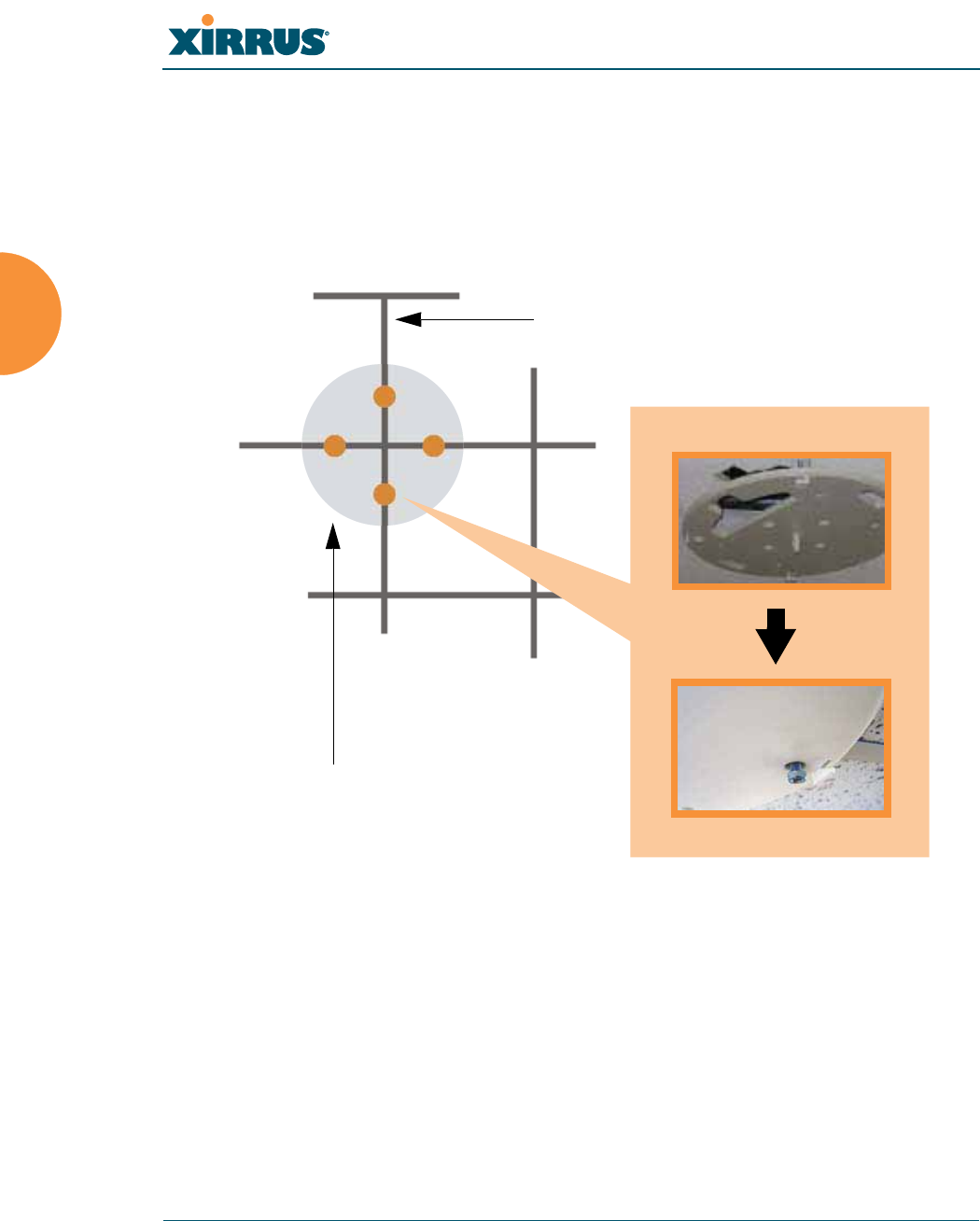
Wi-Fi Array
88 Installing the Wi-Fi Array
Installing the Mounting Plate
Locate the mounting plate on the four screw posts. Secure the plate to the four
clamps using the nuts provided. Tighten the nuts to 10-12 lbf.ft (1.38-1.66 kgf.m),
but do not overtighten.
Cut an access hole for the cables in the ceiling tile.
Figure 39. Installing the Mounting Plate
Tile grid
Mounting Plate
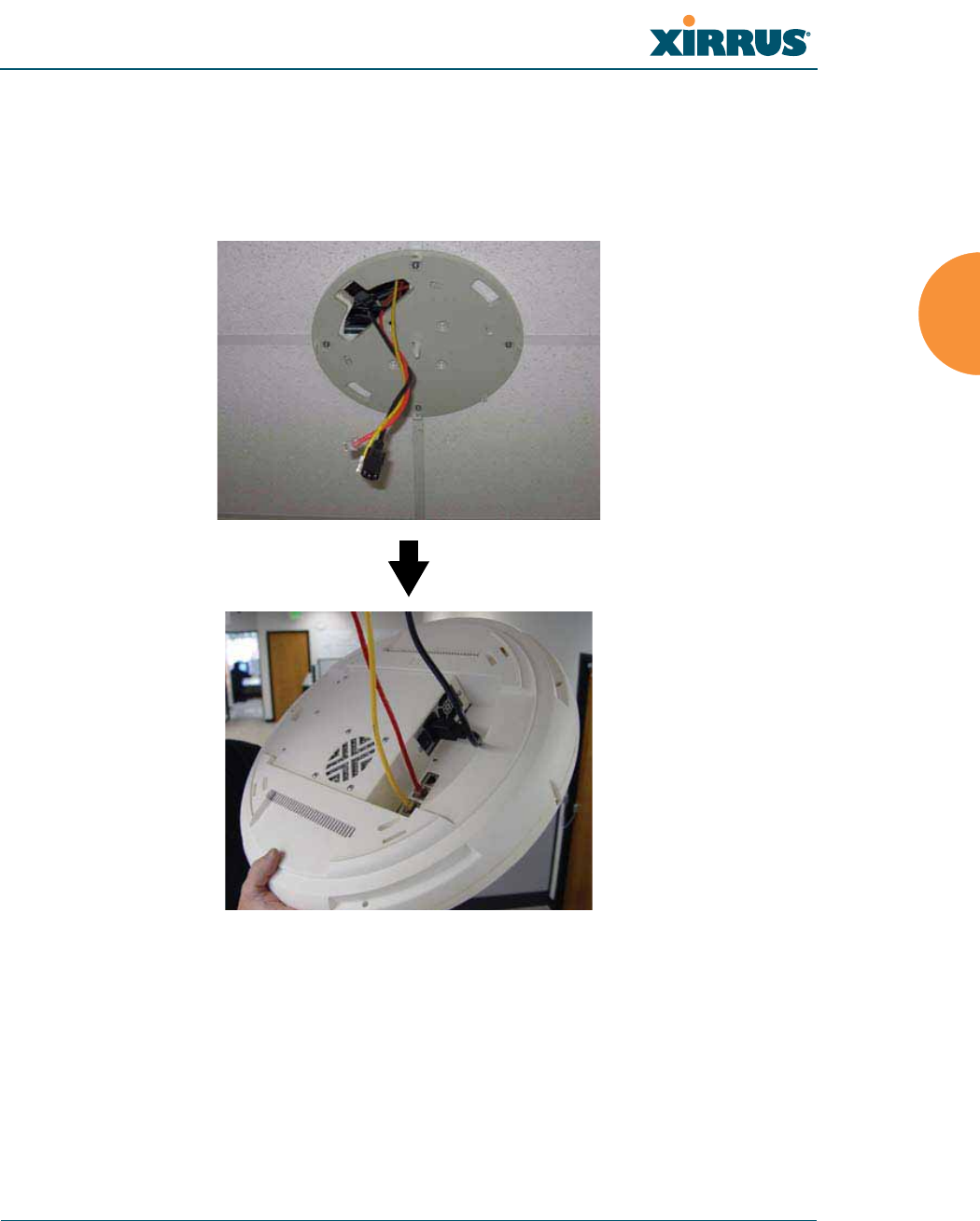
Wi-Fi Array
Installing the Wi-Fi Array 89
Connecting the Cables—AC Option
This section is for Array models that have a separate AC input. If supplying AC to
the Array directly (not using PoGE), refer to Figure 40 to connect cables.
Otherwise, skip to Connecting the Cables—PoGE Option.
Figure 40. Connecting the Cables
Feed the power and Ethernet cables through the access hole in the tile and the
mounting plate, then connect the cables to the Array. See also, “Wiring
Considerations” on page 84.
z
AC power cord—connect to AC source and AC socket on Array.
z
Gigabit1 (mandatory)—the Array’s primary data and management port.
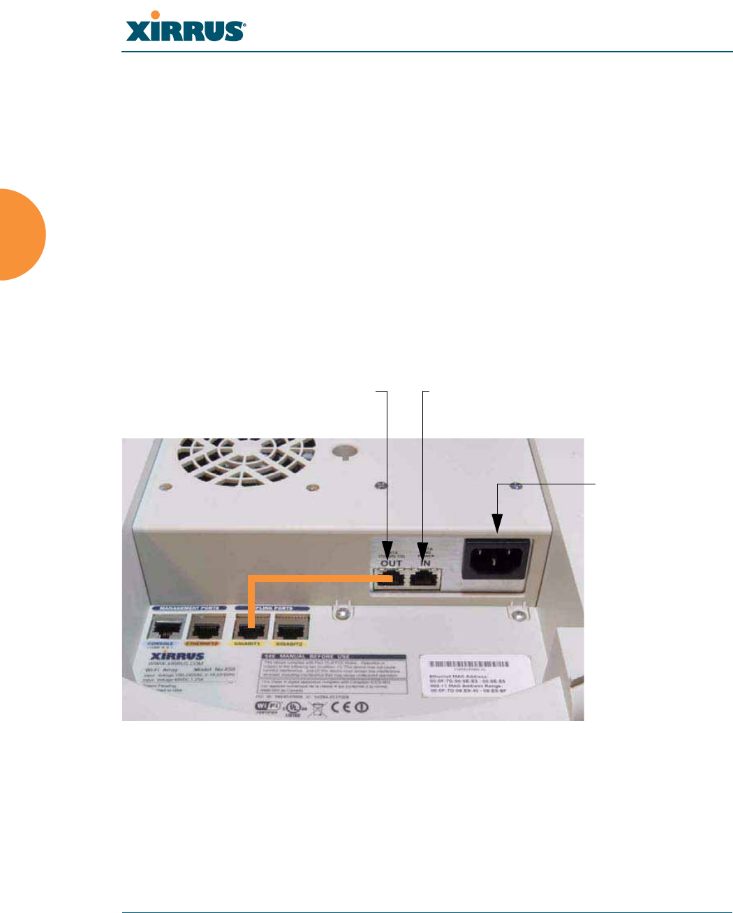
Wi-Fi Array
90 Installing the Wi-Fi Array
z
Gigabit2 (optional)—may be used for load balancing, fail-over, mirroring,
or increasing link speed to the wired network.
z
Fast Ethernet (optional)—for a management-only connection to the
Array.
z
Serial cable (optional)—for connecting directly with the Array using CLI.
Connecting the Cables—PoGE Option
For the XS8, XS12, or XS16, use the procedure below and refer to Figure 41. For the
XS4, see “Connecting the Cables—AC Option” on page 89. All of these Array
models have an integrated splitter, so an external splitter is not needed.
For the XS8, XS12, or XS16:
Figure 41. Connecting the Cables (PoGE—XS8/XS12/XS16)
z
Feed the Ethernet cable(s) through the access hole in the ceiling tile and
the mounting plate.
z
Connect the Cat 5e or Cat 6 data cable coming from the PoGE injector to
the Array’s Data and Power IN port as shown in Figure 41.
Connect Data OUT to Gig1
port with short cable
Connect Cat 5e (from
PoGE Injector) to IN port
Optional AC
socket (unused
for PoGE)
8-, 12-, 16-port
Arrays
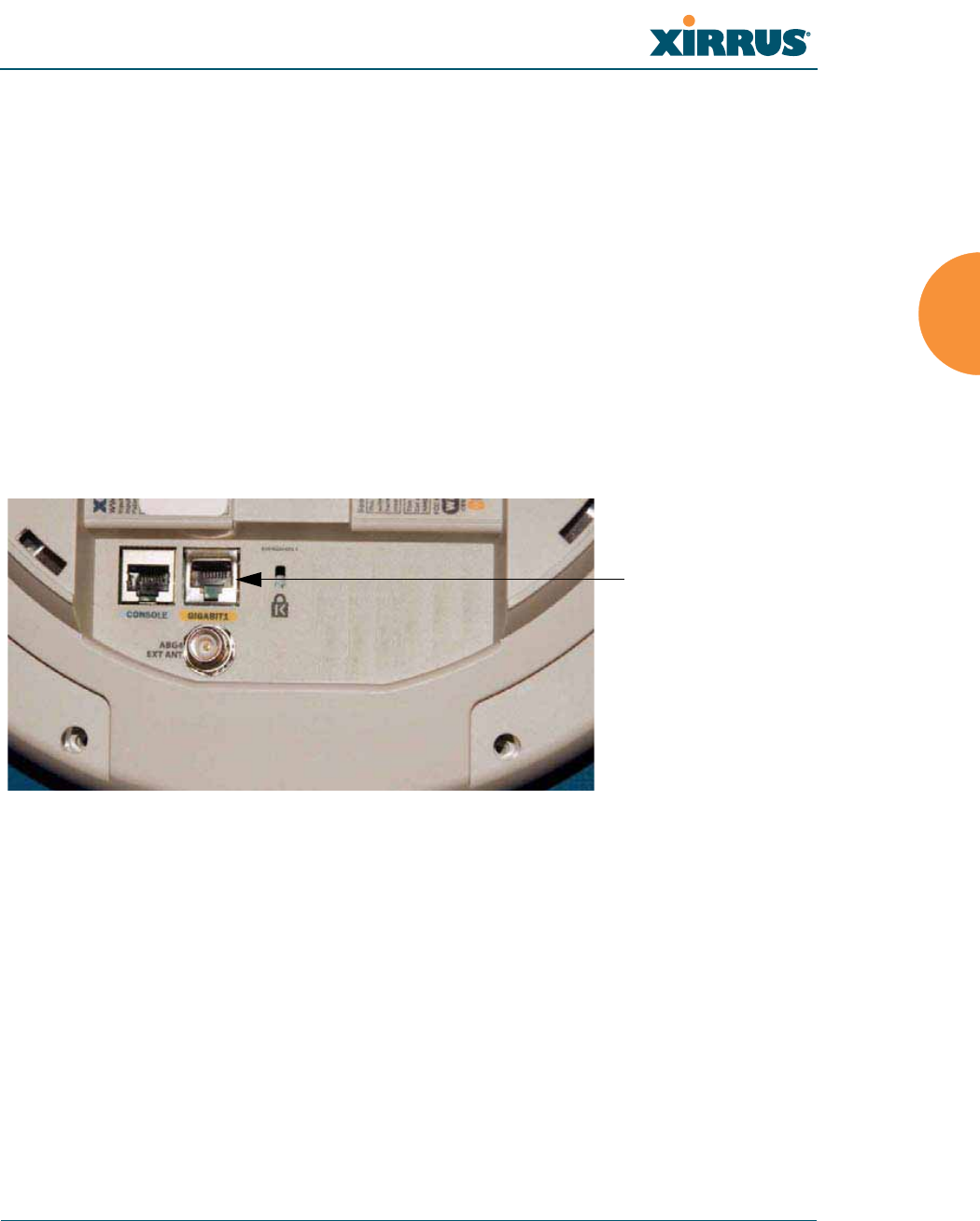
Wi-Fi Array
Installing the Wi-Fi Array 91
z
Connect the supplied 6” orange Cat 5e data cable from the Array’s Data
OUT port to Gigabit1, as shown. Connect any additional Ethernet and
serial cables as required.
For the XS4:
Feed the PoGE cable through the access hole in the ceiling tile and the mounting
plate, then connect the cable to the Gigabit1 port on the XS4 Array. The Gigabit1
port is the data and management connection to the Array. A splitter is integrated
with this port.
Figure 42. Connecting the Cable (PoGE—XS4)
#Do not connect the cable from the injector directly to a Gigabit port! It must
be connected to the IN port (towards the right in Figure 41).
Connect Cat5e
(from PoGE
Injector)
to GIGABIT1
XS4
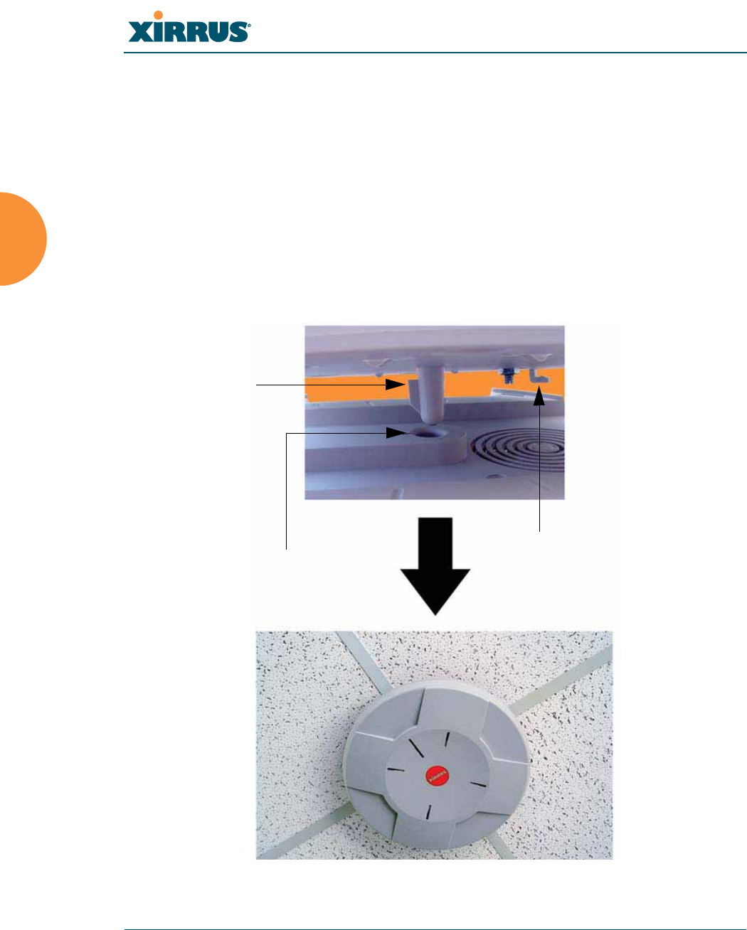
Wi-Fi Array
92 Installing the Wi-Fi Array
Attaching the Array to the Mounting Plate
Mounting all models except XS-3900/XS-3700
Align the Array with the key post on the mounting plate, then turn the Array to
the right to lock the unit into place at the 4 lugs—similar to a smoke detector.
Figure 43. Attaching the Unit (XS4 shown)
#Before attaching the Array to the mounting plate, verify that it is powering
up. The Ethernet link LED lights up and the radio LEDs on the front of the
unit will illuminate in rotation, indicating that the Wi-Fi Array software is
loading and the unit is functioning correctly.
Key post
Lug
Alignment hole
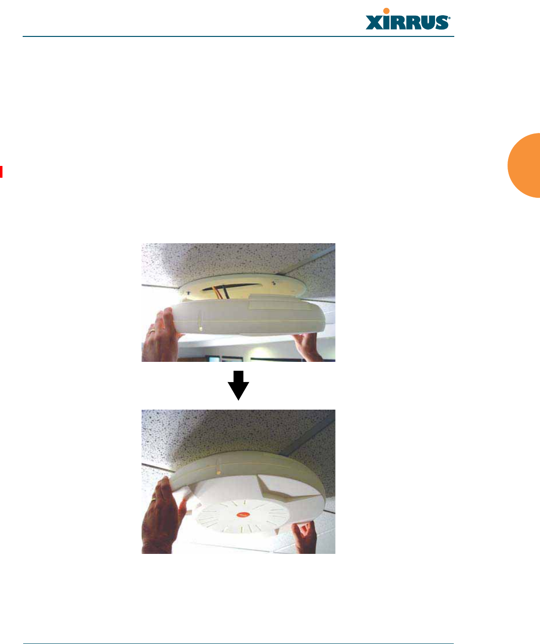
Wi-Fi Array
Installing the Wi-Fi Array 93
See Also
Installation Workflow
Installing Your Wi-Fi Array
Mounting the Wi-Fi Array on a Wall (XS4 and XS-3500)
Mounting Array on a Wall (All models except 4-port Arrays)
Securing the Array
Mounting the XS-3900/XS-3700
Align the port recess on the Array with the access hole in the mounting plate, then
connect the Array with the lugs on the mounting plate (4 places) and turn the
Array clockwise to lock the unit into place (similar to a smoke detector).
Figure 44. Attaching the Unit (XS-3900)

Wi-Fi Array
94 Installing the Wi-Fi Array
Securing the Array
For added security, there is a locking bracket incorporated into the mounting
plate, which will accept a small luggage-style padlock (if desired). There is also a
Kensington lock slot located near the Ethernet ports. In addition, the mounting
plate incorporates a positive locking tab that prevents the unit from being
inadvertently released.
Figure 45. Securing the Array
Now that the Array is physically installed, you must run the Express Setup
procedure from the unit’s Web Management Interface to enable the radios and
establish initial system configuration settings. Go to “Powering Up the Wi-Fi
Array” on page 107.
See Also
Installation Workflow
Installing Your Wi-Fi Array
Mounting the Wi-Fi Array on a Wall (XS4 and XS-3500)
Mounting Array on a Wall (All models except 4-port Arrays)
Mounting the Array on a Ceiling
Powering Up the Wi-Fi Array
Locking bracket
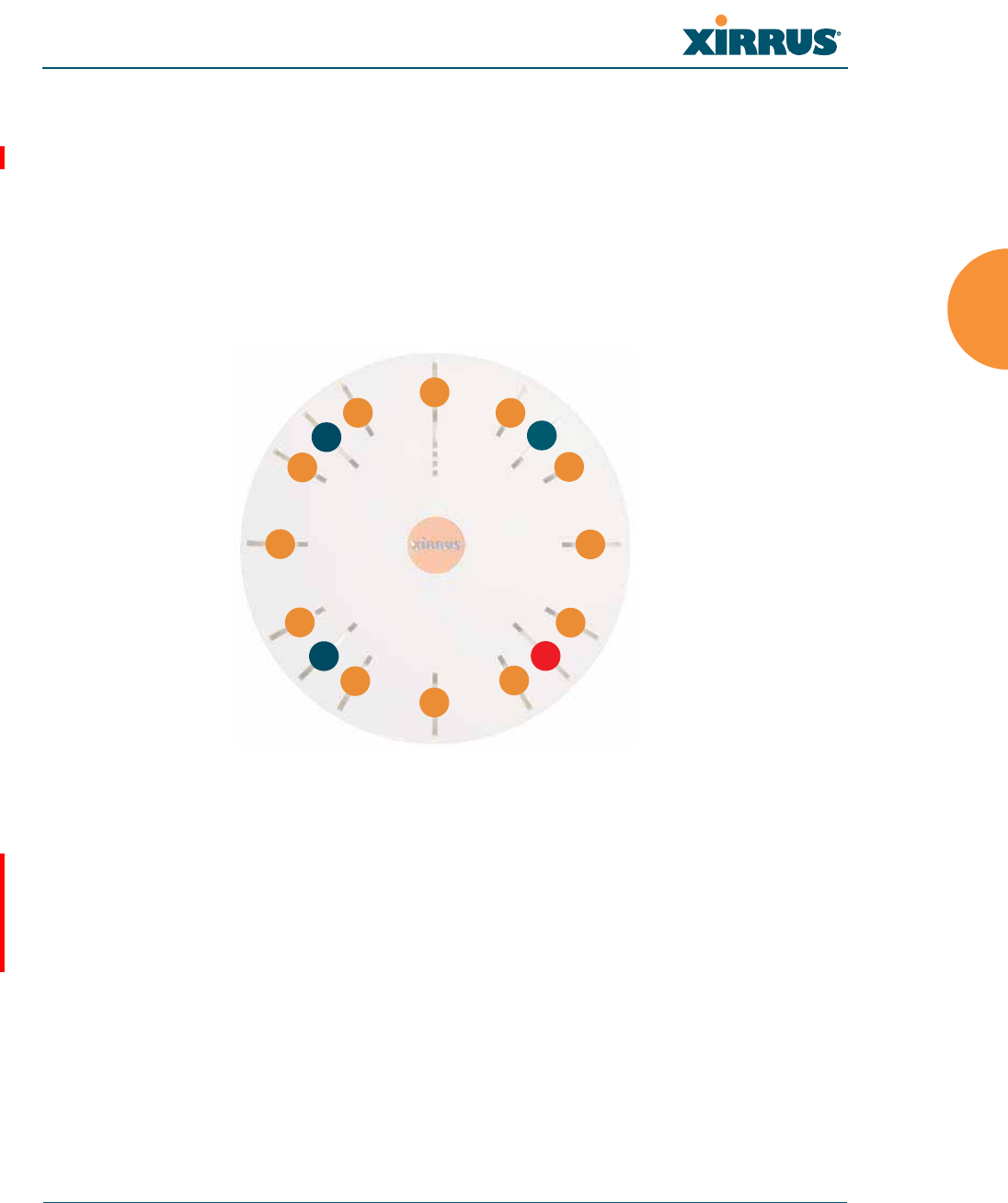
Wi-Fi Array
Installing the Wi-Fi Array 95
Dismounting the Array
To dismount the XS-3700/3900
To dismount the Array, place your fingers so as to increase the space between the
Array and the mounting plate at the positions indicated by the decals on the
mounting plate—these are aligned with IAPs (radios) abg(n)1 and abg(n)3, as
indicated on the clock-face of the Array.
Figure 46. IAP Positions (XS16 shown)
To dismount any other Array model
For all Array models other than the XS-3700/3900, push up on the Array (i.e.,
push it against the mounting plate). Then turn the Array to the left to remove it.
This is similar to dismounting a smoke detector.
See Also
Installation Workflow
Installing Your Wi-Fi Array
Mounting the Wi-Fi Array on a Wall (XS4 and XS-3500)
Mounting Array on a Wall (All models except 4-port Arrays)
Mounting the Array on a Ceiling
a1
abg1
a2
a3
a4
abg2
a5
a6
a7
abg3
a8
a9
a10
abg4
a11
a12

Wi-Fi Array
96 Installing the Wi-Fi Array
Securing the Array
Mounting Array on a Wall (All models except 4-port Arrays)
This procedure is applicable to the Wi-Fi Array’s 16-radio models, 12-radio
models, and 8-radio models. If you are mounting a 4-radio model, go to
“Mounting the Wi-Fi Array on a Wall (XS4 and XS-3500)” on page 101.
The wall mounting assembly kit is used to mount the Wi-Fi Array (except for 4-
port models) on a wall, instead of the traditional ceiling mount—if mounting the
Array on the ceiling is impractical at your location.
Kit Contents (Wall Mount Assembly)
The wall mount assembly kit includes the following items:
z
5 x SNAPTOGGLE™ toggle bolts (for attaching the wall bracket to the
wall)
z
4 x 1/4 inch bolt assemblies (for attaching the mounting plate to the wall
bracket)
z
Wall Mounting Bracket
Tools Required
z
Power drill
z
1/2 inch (13mm) drill bit
z
Cross head screwdriver
z
1/4 inch nut wrench
z
Pencil
z
Level
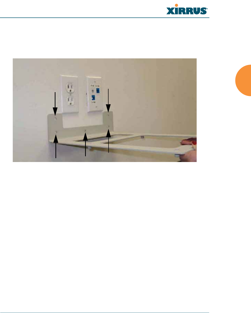
Wi-Fi Array
Installing the Wi-Fi Array 97
Mark the Wall Position
1. Use the Wall Mounting Bracket as a template and mark the locations on
the wall for the mounting holes.
Figure 47. Wall Mount—Marking the Holes
When marking the holes, ensure that the mounting plate is level—you
may need assistance.
#The bracket must be secured to the wall in 5 places, using the 2 holes at the
top and the 3 holes at the bottom (5 toggle bolts are provided).
Mark holes (5 places)
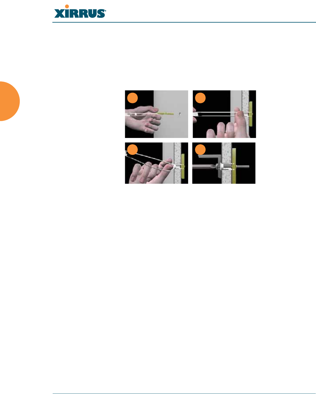
Wi-Fi Array
98 Installing the Wi-Fi Array
Install the SNAPTOGGLE™ Toggle Bolts
2. At the locations you marked in Step 1, drill a 1/2 inch (13mm) hole (there
must be a minimum clearance behind the wall of 1 7/8 inches—48mm).
3. (Refer to Figure 48, graphic A) Hold the metal channel flat alongside the
plastic straps and slide the channel through the hole.
Figure 48. Installing the Toggle Bolts
4. (Refer to Figure 48, graphic B) Hold the strap handle between your
thumb and forefinger and pull towards you until the metal channel rests
flush behind the wall.
Using your other hand, now slide the plastic cap along the straps until the
flange of the cap is flush with wall.
The straps provide a one-way ratcheting mechanism (similar to a cable tie).
Ensure that the toggle bolt assembly is oriented correctly (as shown) before
sliding the plastic cap along the straps.
5. (Refer to Figure 48, graphic C) Break the straps at the wall, flush with the
flange of the cap. The straps can be broken by pushing them from side-to-
side and simply snapping them off.
Figure 48, Graphic D shows a cutaway example of how the toggle bolt is
used to secure an item to the wall (in our case, the item is the Wall
Mounting Bracket—secured to the wall with 5 toggle bolts.
Do not attach the Wall Mounting Bracket to the wall at this time.
AB
C D
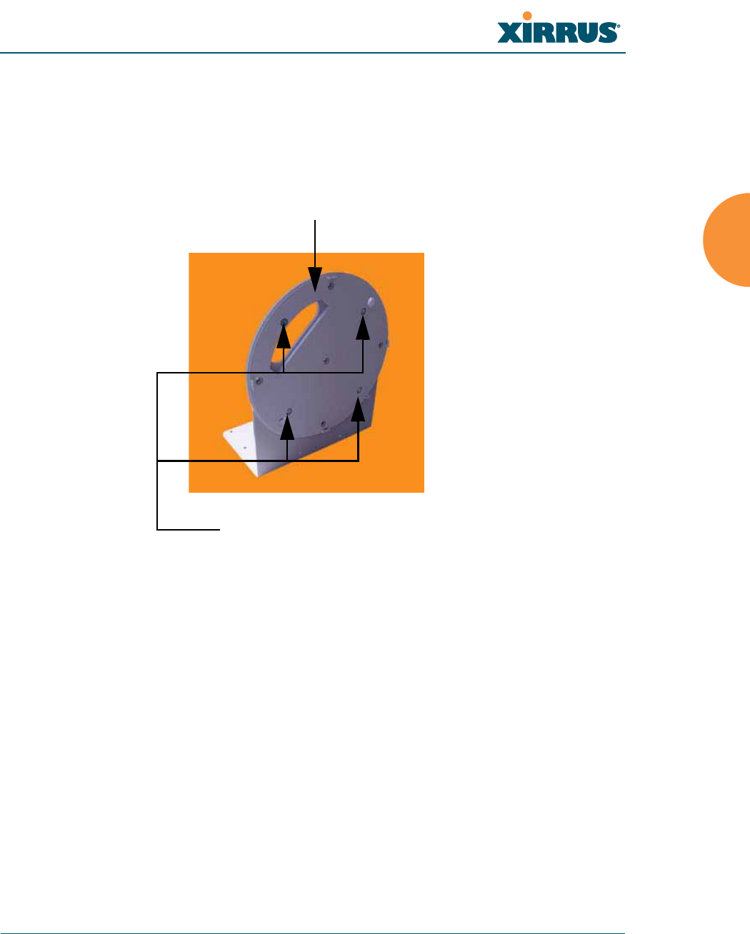
Wi-Fi Array
Installing the Wi-Fi Array 99
Attach the Mounting Plate to the Wall Mounting Bracket
6. Secure the Wi-Fi Array’s mounting plate to the Wall Mounting Bracket, in
4 places. Tighten the bolts to a torque of 10–12 lbf.ft (1.38–1.66 kgf.m).
Do not overtighten the bolts.
Figure 49. Attaching the Wall Mounting Plate
Attach the Wall Mounting Bracket/Plate Assembly to the Wall
7. Secure the Wall Mounting Bracket (with attached Mounting Plate) to the
wall at the 5 toggle bolt anchors you created in Steps 1 through 5—using
all 5 places.
Mounting Plate
Secure (x4 bolt assemblies)

Wi-Fi Array
100 Installing the Wi-Fi Array
Mount the Array
8. Mount the Wi-Fi Array to the Wall Mounting Bracket in the same way
that you would mount the Array to a ceiling mount (the procedure is
identical). See “Attaching the Array to the Mounting Plate” on page 92 or
“Mounting the XS-3900/XS-3700” on page 93.
Figure 50. Mounting the Array on a Wall
See Also
Installation Workflow
Installing Your Wi-Fi Array
Mounting the Wi-Fi Array on a Wall (XS4 and XS-3500)
Mounting the Array on a Ceiling
Securing the Array
#Figure 50 shows the orientation of the Wi-Fi Array when mounted on a wall.
It is not intended to show a fully installed Array.

Wi-Fi Array
Installing the Wi-Fi Array 101
Mounting the Wi-Fi Array on a Wall (XS4 and XS-3500)
This procedure is applicable to the 4 radio models of the Wi-Fi Array (XS4 and
XS-3500). If you are mounting a 16-, 12-, or 8-radio model, go to “Mounting Array
on a Wall (All models except 4-port Arrays)” on page 96.
The wall mounting assembly kit is used to mount a 4-port Wi-Fi Array on a wall,
instead of the traditional ceiling mount—where mounting the Array on the
ceiling may be impractical at your location.
Kit Contents (Wall Mount Assembly)
The wall mount assembly kit includes the following items:
z
5 x SNAPTOGGLE™ toggle bolts (for attaching the wall bracket to the
wall)
z
4 x 1/4 inch bolt assemblies (for attaching the mounting plate to the wall
bracket)
z
Wall Mounting Bracket
Tools Required
z
Power drill
z
1/2 inch (13mm) drill bit
z
Cross head screwdriver
z
1/4 inch nut wrench
z
Pencil
z
Level
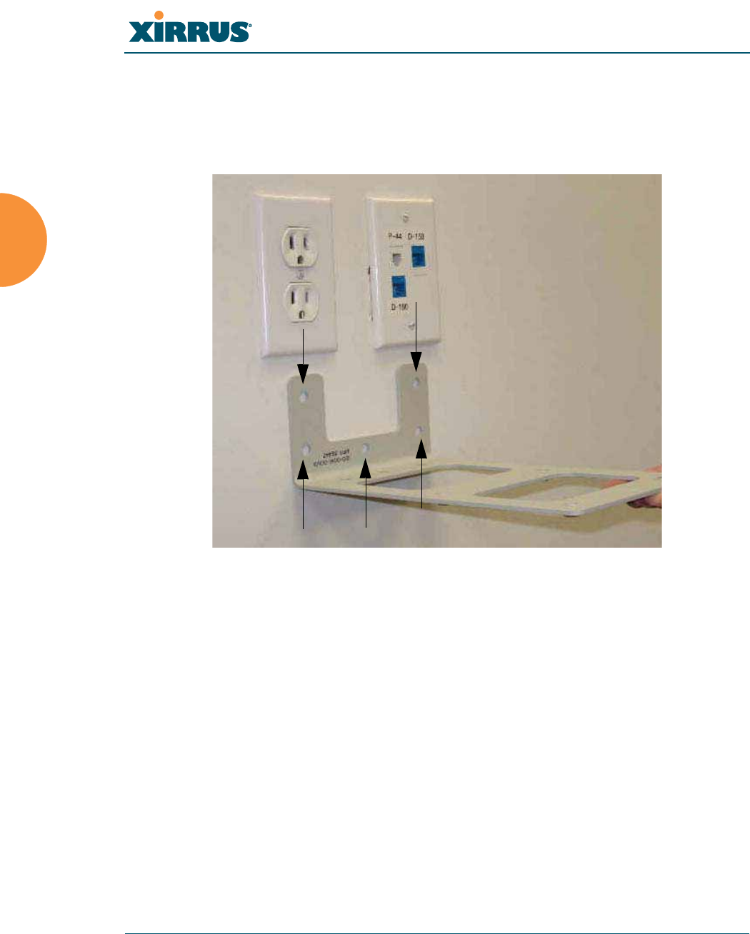
Wi-Fi Array
102 Installing the Wi-Fi Array
Mark the Wall Position
1. Use the Wall Mounting Bracket as a template and mark the locations on
the wall for the mounting holes.
Figure 51. Wall Mount—Marking the Holes
The bracket must be secured to the wall in 5 places, using the top 2 holes
and the bottom 3 holes (5 toggle bolts are provided).
When marking the holes, ensure that the mounting plate is level—you
may need assistance.
Install the SNAPTOGGLE™ Toggle Bolts
2. At the locations you marked in Step 1, drill a 1/2 inch (13mm) hole (there
must be a minimum clearance behind the wall of 1 7/8 inches—48mm).
Mark holes (5 places)

Wi-Fi Array
Installing the Wi-Fi Array 103
3. (Refer to Figure 52, graphic A) Hold the metal channel flat alongside the
plastic straps and slide the channel through the hole.
Figure 52. Installing the Toggle Bolts
4. (Refer to Figure 52, graphic B) Hold the strap handle between your
thumb and forefinger and pull towards you until the metal channel rests
flush behind the wall.
Using your other hand, now slide the plastic cap along the straps until the
flange of the cap is flush with wall.
The straps provide a one-way ratcheting mechanism (similar to a cable tie).
Ensure that the toggle bolt assembly is oriented correctly (as shown) before
sliding the plastic cap along the straps.
5. (Refer to Figure 52, graphic C) Break the straps at the wall, flush with the
flange of the cap. The straps can be broken by pushing them from side-to-
side and simply snapping them off.
Figure 52, Graphic D shows a cutaway example of how the toggle bolt is
used to secure an item to the wall (in our case, the item is the Wall
Mounting Bracket—secured to the wall with 5 toggle bolts).
Do not attach the Wall Mounting Bracket to the wall at this time.
AB
C D
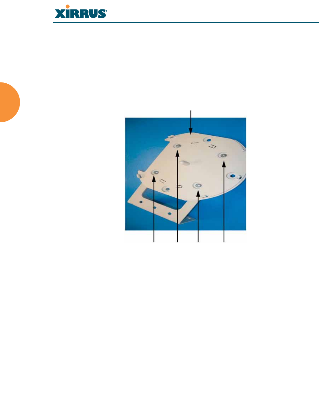
Wi-Fi Array
104 Installing the Wi-Fi Array
Attach the Mounting Plate to the Wall Mounting Bracket
6. Secure the Wi-Fi Array’s mounting plate to the Wall Mounting Bracket, in
4 places.
Tighten the bolts to a torque of 10–12 ft-lb (1.38–1.66 kg.m).
Do not overtighten the bolts.
Figure 53. Attaching the Array Mounting Plate
Secure (x4 bolt assemblies)
Mounting Plate
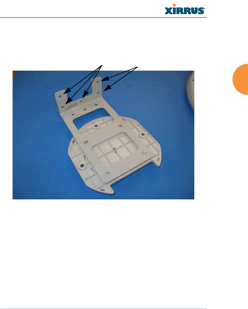
Wi-Fi Array
Installing the Wi-Fi Array 105
Attach the Wall Mounting Bracket/Plate Assembly to the Wall
7. Secure the Wall Mounting Bracket (with attached Mounting Plate) to the
wall at the 5 toggle bolt anchors you created in Steps 2 through 5—using
all 5 places.
Figure 54. Attaching the Wall Mounting Bracket to the Wall
Secure with 5 toggle bolts
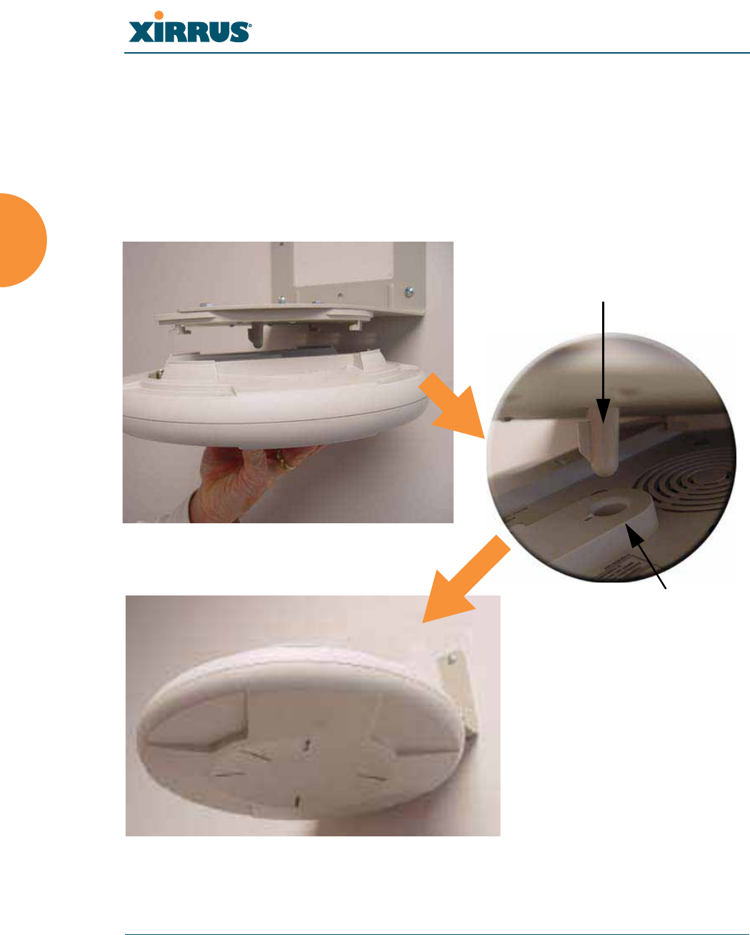
Wi-Fi Array
106 Installing the Wi-Fi Array
Mount the Array
8. Mount the Wi-Fi Array to the Wall Mounting Bracket by positioning the
key post (on the underside of the mounting bracket) into the key
receptacle on the underside of the Array.
When the key post is properly located, gently turn the Array in a
clockwise direction to secure the Array to the mounting plate.
Figure 55. Mounting the Array on a Wall
Key Post (Mounting Bracket)
Receptacle
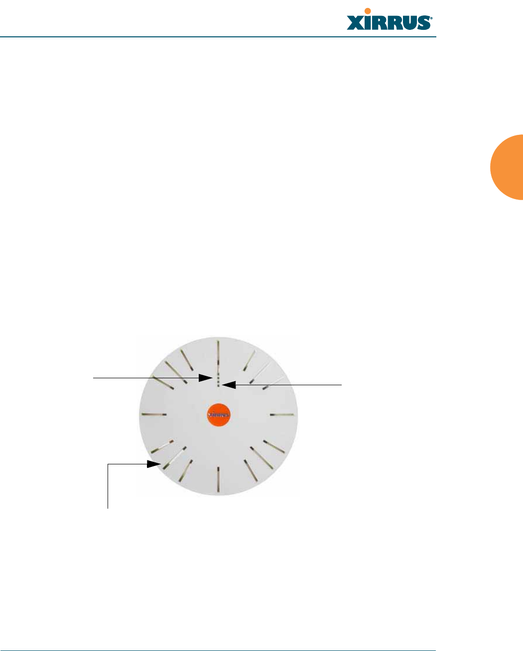
Wi-Fi Array
Installing the Wi-Fi Array 107
Removing the Array
To remove the Array from the Wall Mount Assembly, simply apply a little upward
pressure to the Array, then gently turn the Array in a counterclockwise direction
to release the unit from the bracket.
See Also
Installation Workflow
Installing Your Wi-Fi Array
Mounting Array on a Wall (All models except 4-port Arrays)
Mounting the Array on a Ceiling
Securing the Array
Powering Up the Wi-Fi Array
When powering up, the Array follows a specific sequence of LED patterns
showing the boot progress, and following a successful boot will provide extensive
status information.
Figure 56. LED Locations (XS-3900)
Array LED settings may be altered or disabled entirely for diagnostic purposes or
for personal preference. Changes are made via the Array’s Command Line
Interface or the Web Management Interface—refer to “LED Settings” on page 283.
Status LED
Ethernet Activity
LEDs
IAP LEDs (x16)
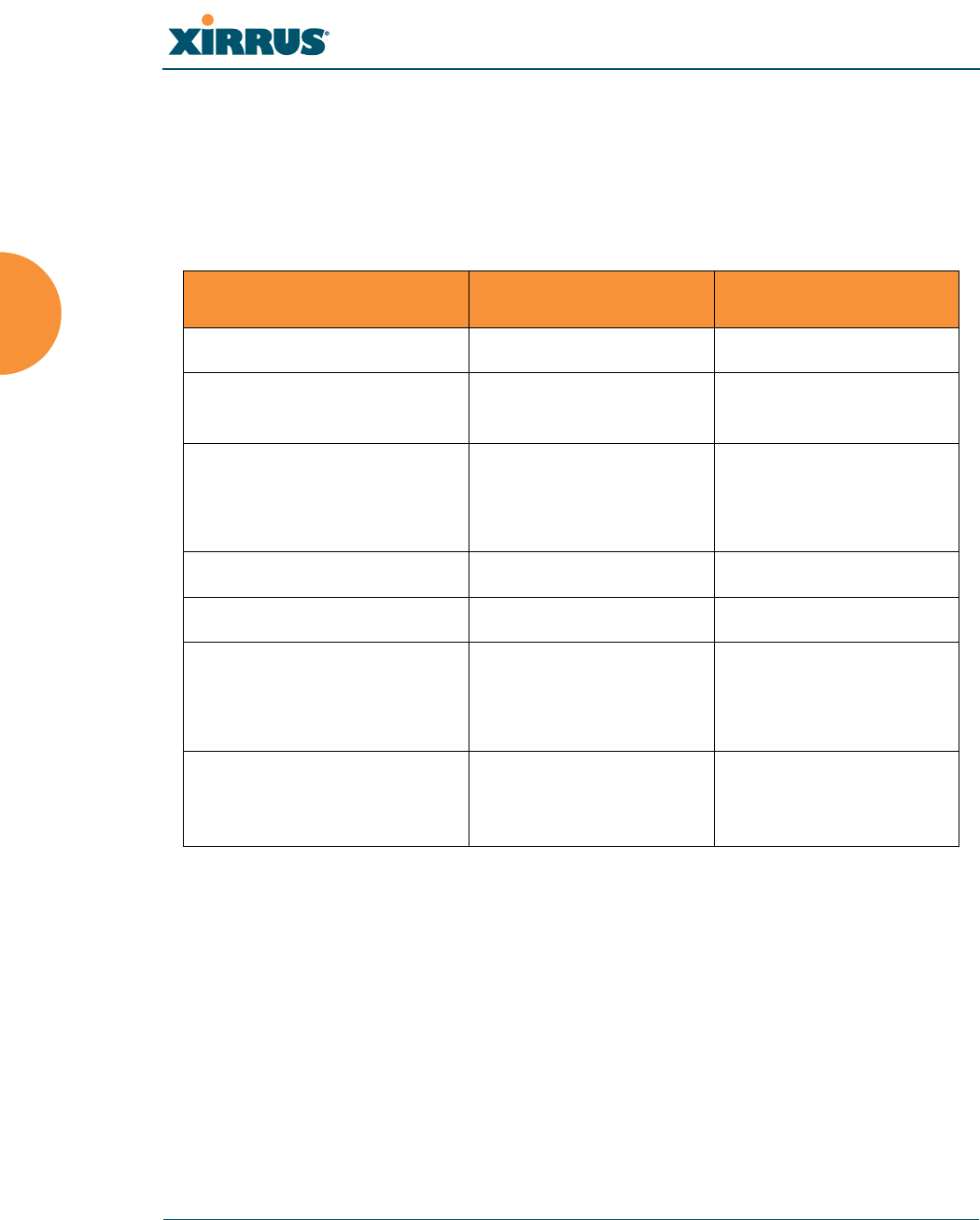
Wi-Fi Array
108 Installing the Wi-Fi Array
Array LED Operating Sequences
Use the following tables to review the operating sequences of the Array’s LEDs.
LED Boot Sequence
The normal boot LED sequence is as follows:
Array Activity Status LED IAP LEDs
Power ON Blinking GREEN All OFF
Boot loader power ON
self-test
Blinking GREEN All ON
Image load from
compact FLASH
Blinking GREEN Spinning pattern
(rotate all to ON, then
all to OFF)
Image load failure Blinking RED All OFF
Hand off to ArrayOS Solid GREEN All OFF
System software
initialization
Solid GREEN Walking pattern
(LED rotating one
position per second)
Up and running Solid GREEN ON for IAPs that are
up, and OFF for IAPs
that are down

Wi-Fi Array
Installing the Wi-Fi Array 109
LED Operation when Array is Running
The normal LED operation when the Array is running is as follows:
See Also
Installation Prerequisites
Installation Workflow
Installing Your Wi-Fi Array
LED Status Reason
IAP LED is OFF IAP is down
IAP LED is solid ON IAP is up, but no associations and
no traffic
IAP LED heartbeat IAP is up, with stations
associated but no traffic
IAP LED flashing
Flashing at 10 Hz
Flashing at 5 Hz
Flashing at 2.5 Hz
IAP is up, passing traffic
Traffic > 1500 packets/sec
Traffic > 150 packets/sec
Traffic > 1 packet/sec
IAP LED is GREEN IAP is operating in the 2.4 GHz
band
IAP LED is ORANGE IAP is operating in the 5 GHz
band
IAP LED flashing ORANGE to
GREEN at 1 Hz
IAP abg(n)2 is in monitor mode
(standard intrude detect)
Ethernet LEDs are dual color
Ethernet LED is ORANGE
Ethernet LED is GREEN
Transferring data at 1 Gbps
Transferring data at 10/100 Mbps
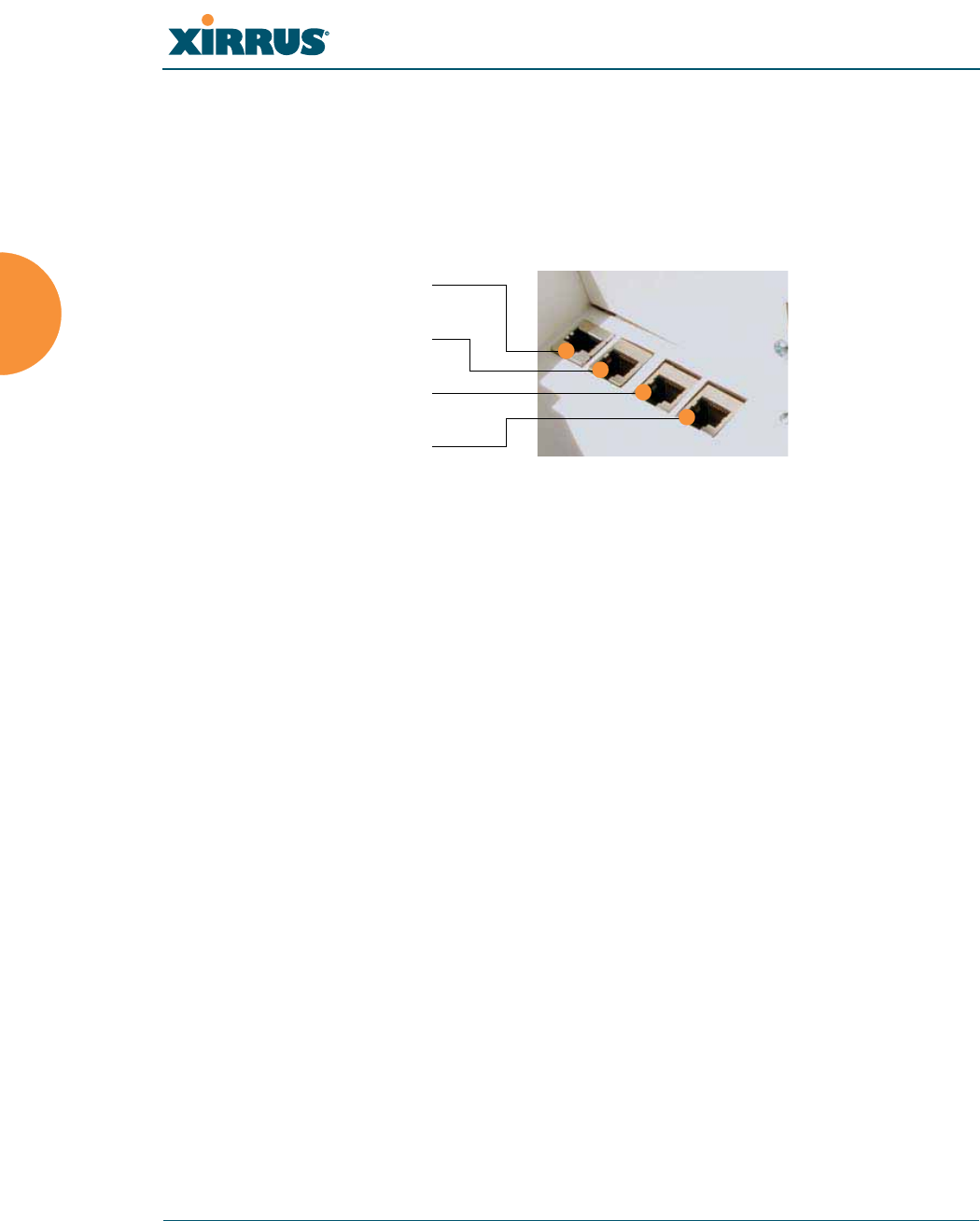
Wi-Fi Array
110 Installing the Wi-Fi Array
Establishing Communication with the Array
The Array can be configured through the Command Line Interface (CLI) or the
graphical Web Management Interface (WMI). You can use the CLI via the serial
management port, the Fast Ethernet port, or either of the Gigabit Ethernet ports.
You can use the WMI via any of the Array’s Ethernet ports.
Figure 57. Network Interface Ports
Using the Serial Port
If using the serial port to make your connection, use serial settings of 8 bits, no
parity, no flow control, 1 stop bit (8N1) and a speed setting of 115200 baud. Use
the communication package of your choice.
Using the Ethernet Ports
By default, the Array's Ethernet interfaces use DHCP to obtain an IP address. If
the Array is booted and does not receive DHCP addresses on either the Fast
Ethernet or Gigabit Ethernet ports, the Fast Ethernet port will default to an IP
address of 10.0.1.1 and both Gigabit Ethernet ports will default to 10.0.2.1. If the
Array is connected to a network that provides DHCP addresses, the IP address
can be determined by the following two methods:
1. Examine the DHCP tables on the server and find the addresses assigned
to the Array (Xirrus MAC addresses begin with 000F7D).
2. Query the Array using the CLI via the serial port. Use the show ethernet
command to view the IP addresses assigned to each port.
Serial
Fast Ethernet
Gigabit 1
Gigabit 2

Wi-Fi Array
Installing the Wi-Fi Array 111
Logging In
When logging in to the Array, use the default user name and password—the
default user name is admin, and the default password is admin.
See Also
Installation Workflow
Performing the Express Setup Procedure
Powering Up the Wi-Fi Array
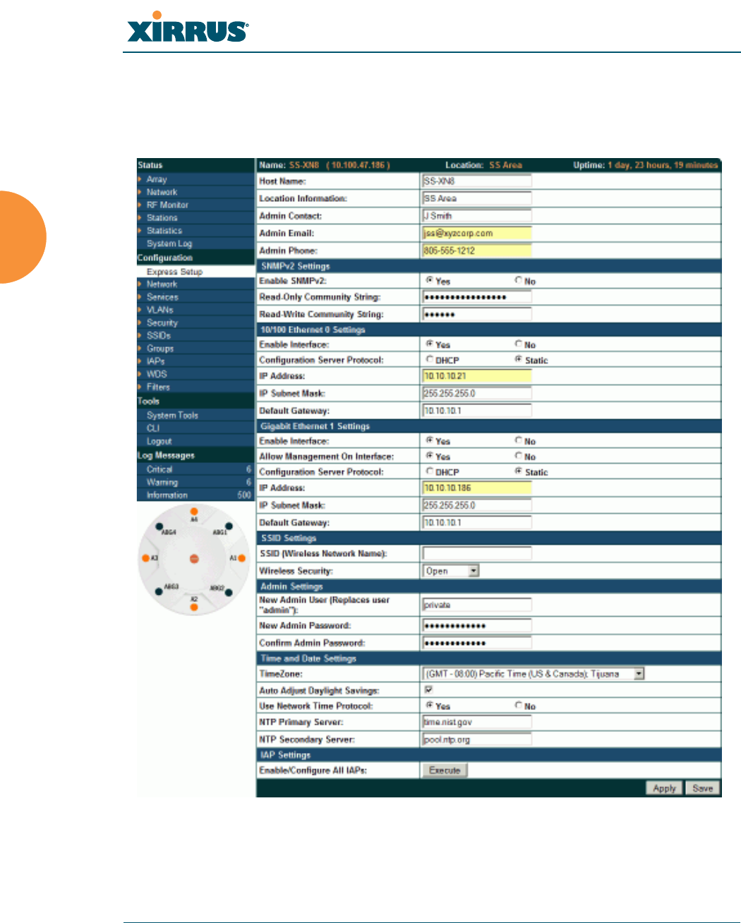
Wi-Fi Array
112 Installing the Wi-Fi Array
Performing the Express Setup Procedure
The Express Setup procedure establishes global configuration settings that enable
basic Array functionality. Changes made in this window will affect all radios.
Figure 58. Express Setup

Wi-Fi Array
Installing the Wi-Fi Array 113
Procedure for Performing an Express Setup
1. Host Name: Specify a unique host name for this Array. The host name is
used to identify the Array on the network. Use a name that will be
meaningful within your network environment, up to 64 alphanumeric
characters. The default is Xirrus-WiFi-Array.
2. Location Information: Enter a brief but meaningful description that
accurately defines the physical location of the Array. In an environment
where multiple units are installed, clear definitions for their locations are
important if you want to identify a specific unit.
3. Admin Contact: Enter the name and contact information of the person
who is responsible for administering the Array at the designated location.
4. Admin Email: Enter the email address of the admin contact you entered
in Step 3.
5. Admin Phone: Enter the telephone number of the admin contact you
entered in Step 3.
6. Configure SNMPv2: Select whether to Enable SNMPv2 on the Array, and
change the SNMP Community Strings if desired. If you are using the
Xirrus Management System (XMS), these strings must match the values
used by XMS. The default values for the Array match the defaults in
XMS. For more details, including SNMPv3, see “SNMP” on page 200.
7. Configure the Fast Ethernet (10/100 Megabit), Gigabit 1 and Gigabit 2
network interfaces. The fields for each of these interfaces are the same,
and include:
a. Enable Interface: Choose Yes to enable this network interface, or
choose No to disable the interface.
b. Allow Management on Interface: Choose Yes to allow management
of the Array via this network interface, or choose No to deny all
management privileges for this interface.
c. Configuration Server Protocol: Choose DHCP to instruct the Array
to use DHCP to assign IP addresses to the Array’s Ethernet interfaces,

Wi-Fi Array
114 Installing the Wi-Fi Array
or choose Static if you intend to enter IP addresses manually. If you
choose the Static IP option, you must enter the following information:
z
IP Address: Enter a valid IP address for this Array. To use any of
the remote connections (Web, SNMP, or SSH), a valid IP address
must be used.
z
IP Subnet Mask: Enter a valid IP address for the subnet mask
(the default is 255.255.255.0). The subnet mask defines the
number of IP addresses that are available on the routed subnet
where the Array is located.
z
Default Gateway: Enter a valid IP address for the default
gateway. This is the IP address of the router that the Array uses
to forward data to other networks.
8. SSID Settings: This section specifies the wireless network name and
security settings.
a. SSID (Wireless Network Name): The SSID (Service Set Identifier) is
a unique name that identifies a wireless network. All devices
attempting to connect to a specific WLAN must use the same SSID.
The default for this field is “xirrus.”
For additional information about SSIDs, go to the Multiple SSIDs
section of “Frequently Asked Questions” on page 398.
b. Wireless Security: Select the desired wireless security scheme (Open,
WEP, WPA, WPA2, or WPA-Both). WPA2 is recommended for the
best Wi-Fi security.
•Open—This option offers no data encryption and is not
recommended, though you might choose this option if clients are
required to use a VPN connection through a secure SSH utility,
like PuTTy.
•WEP (Wired Equivalent Privacy)—An optional IEEE 802.11
function that offers frame transmission privacy similar to a wired
network. WEP generates secret shared encryption keys that both
source and destination stations can use to alter frame bits to
avoid disclosure to eavesdroppers.

Wi-Fi Array
Installing the Wi-Fi Array 115
•WPA (Wi-Fi Protected Access)—A Wi-Fi Alliance standard that
contains a subset of the IEEE 802.11i standard, using TKIP or AES
as an encryption method and 802.1x for authentication.
•WPA2 (Wi-Fi Protected Access 2)—WPA2 is the follow-on
security method to WPA for wireless networks and provides
stronger data protection and network access control. It offers
Enterprise and consumer Wi-Fi users with a high level of
assurance that only authorized users can access their wireless
networks. Like WPA, WPA2 is designed to secure all versions of
802.11 devices, including 802.11a, 802.11b, 802.11g, and 802.11n,
multi-band and multi-mode.
•WPA-Both (WPA and WPA2)—This option makes use of both
WPA and WPA2.
For more information about security, including a full review of all
security options and settings, go to “Understanding Security” on
page 210.
c. Wireless Key/Passphrase: Depending on the wireless security
scheme you selected, enter a unique WEP key or WPA passphrase.
d. Confirm Key/Passphrase: If you entered a WEP key or WPA
passphrase, confirm it here.
9. Admin Settings: This section allows you to change the default password
for the Array. Note that the Array also offers the option of authenticating
administrators using a RADIUS server (see “Admin Management” on
page 215).
a. New Admin Password: If desired, enter a new administration
password for managing this Array. Choose a password that is not
obvious, and one that you can remember. If you forget your
password, you must reset the Array to its factory defaults so that the
password is reset to admin (its default setting).
b. Confirm Admin Password: If you entered a new administration
password, confirm the new password here.

Wi-Fi Array
116 Installing the Wi-Fi Array
10. Time and Date Settings: This section specifies an optional time (NTP -
Network Time Protocol) server or modifies the system time if you’re not
using a server.
a. Time Zone: Select your time zone from the choices available in the
pull-down list.
b. Use Network Time Protocol: Check this box if you want to use an
NTP server to synchronize the Array’s clock. This ensures that Syslog
time-stamping is maintained across all units. Without an NTP server
assigned (no universal clock), each Array will use its own internal
clock and stamp times accordingly, which may result in
discrepancies. If you check Yes, the NTP server fields are displayed. If
you don’t want to use an NTP server, leave this box unchecked
(default) and set the system time on the Array manually.
c. NTP Primary Server: If you are using NTP, enter the IP address or
domain name of the NTP server.
d. NTP Secondary Server: Enter the IP address or domain name of an
optional secondary NTP server to be used in case the Array is unable
to contact the primary server.
e. Set Time (hrs:min:sec): If you are not using NTP, check this box if
you want to adjust the current system time. When the box is checked,
the time fields become active. Enter the revised time (hours, minutes,
seconds, am/pm) in the corresponding fields. If you don’t want to
adjust the current time, this box should be left unchecked (default).
f. Set Date (month/day/year): If you are not using NTP, check this box if
you want to adjust the current system date. When the box is checked,
the date fields become active. Enter the revised date (month, day and
year) in the corresponding fields. If you don’t want to adjust the
current date, this box should be left unchecked (default).
g. Auto Adjust Daylight Savings: If you are not using NTP, check this
box if you want the system to adjust for daylight savings
automatically, otherwise leave this box unchecked (default).
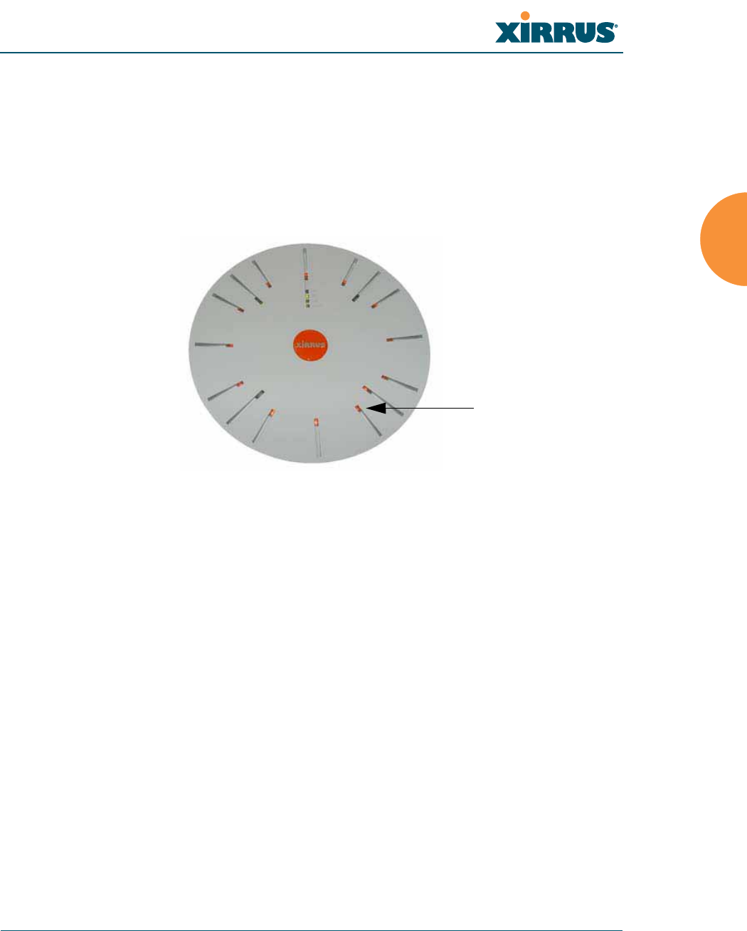
Wi-Fi Array
Installing the Wi-Fi Array 117
11. IAP Settings:
Enable/Configure All IAPs: Click on the Execute button to enable and
auto configure all IAPs (a message displays the countdown time—in
seconds—to complete the auto-configuration task). When an IAP is
enabled, its LED is switched on. (Figure 59)
Figure 59. LEDs are Switched On
12. Click on the Apply button to apply the new settings to this session
13. Click on the Save button to save your changes (otherwise your new
settings will not take effect).
This ends the Express Setup procedure.
See Also
Establishing Communication with the Array
Installation Prerequisites
Installation Workflow
Logging In
Multiple SSIDs
Security
LED on

Wi-Fi Array
118 Installing the Wi-Fi Array

Wi-Fi Array
The Web Management Interface 119
The Web Management Interface
This topic provides an overview of the Xirrus Wi-Fi Array’s embedded Web
Management Interface (WMI), used for establishing your network’s configuration
settings and wireless operating parameters. It also includes login instructions.
The following topics are discussed:
z
An Overview
z
Structure of the WMI
z
User Interface
z
Logging In
z
Applying Configuration Changes
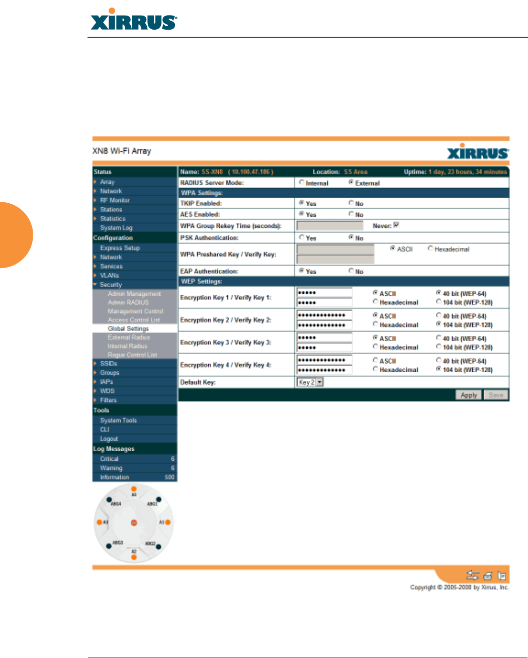
Wi-Fi Array
120 The Web Management Interface
An Overview
The WMI is an easy-to-use graphical interface to your Wi-Fi Array. It allows you
to configure the product to suit your individual requirements and ensure that the
unit functions efficiently and effectively.
Figure 60. Web Management Interface

Wi-Fi Array
The Web Management Interface 121
Structure of the WMI
The content of the WMI is organized by function and hierarchy, shown in the
following table. Click on any item below to jump to the referenced destination.
Status Windows
Array Status Windows
Array Summary
Array Information
Array Configuration
Admin History
Network Status Windows
Network Map
Spanning Tree Status
Routing Table
ARP Table
DHCP Leases
Connection Tracking/NAT
CDP Neighbors
RF Monitor Windows
IAPs
Spectrum Analyzer
Intrusion Detection
Station Status Windows
Stations
Location Map
RSSI
Signal-to-Noise Ratio (SNR)
Noise Floor
Max by IAP
Configuration Windows
Express Setup
Network
Network Interfaces
DNS Settings
CDP Settings
Configuration Windows (cont’d)
Services
Time Settings (NTP)
NetFlow
System Log
SNMP
DHCP Server
VLANs
VLAN Management
Security
Admin Management
Admin RADIUS
Management Control
Access Control List
Global Settings
External Radius
Internal Radius
Rogue Control List
SSIDs
SSID Management
Groups
Group Management
IAPs
IAP Settings
Global Settings (IAP)
Global Settings .11a
Global Settings .11bg
Global Settings .11n
Advanced RF Settings
LED Settings
WDS
WDS Client Links
Filters
Filter Lists
Filter Management

Wi-Fi Array
122 The Web Management Interface
Statistics Windows
IAP Statistics Summary
Per-IAP Statistics
Network Statistics
VLAN Statistics
WDS Statistics
Filter Statistics
Station Statistics
Per-Station Statistics
System Log Window
Tool Windows
System Tools
CLI
Logout
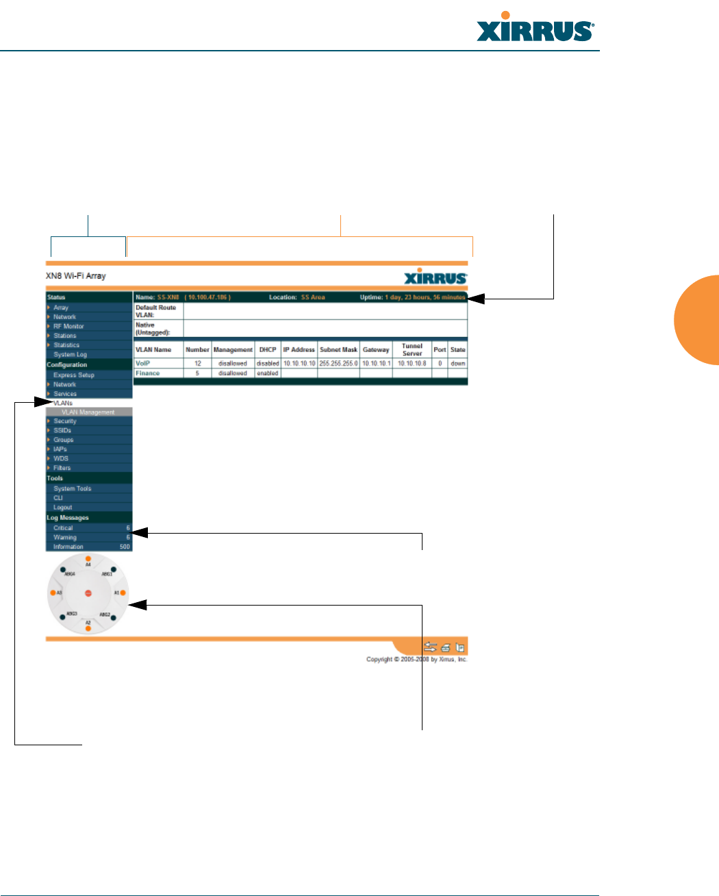
Wi-Fi Array
The Web Management Interface 123
User Interface
The WMI has been designed with simplicity in mind, making navigation quick
and easy. In the following example, you’ll see that windows are divided into left
and right frames.
Figure 61. WMI: Frames
Left frame Right frame Array info
Pull-down menu Click to configure/view statistics
Message counters
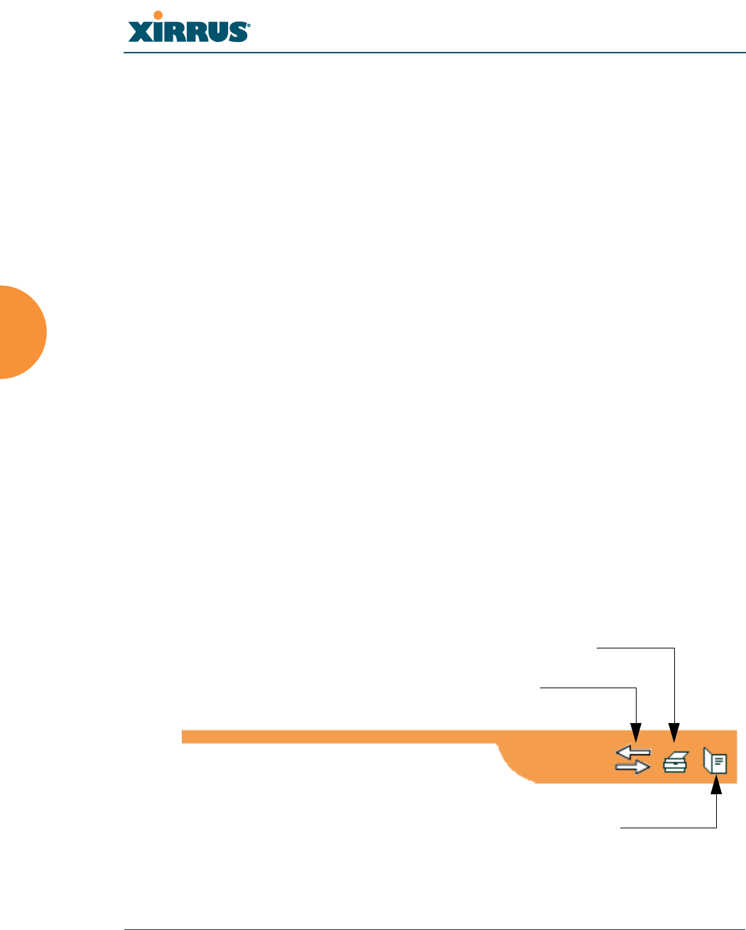
Wi-Fi Array
124 The Web Management Interface
The left frame contains three main elements:
z
Configuration menu organized by function (for example, radio interfaces,
security, etc.). Click the heading to display a summary of its current
configuration, as well as an associated pull-down menu.
z
Three Log Messages counters are located at the bottom of the menu. They
provide a running total of messages generated by the ArrayOS Syslog
subsystem during your session—organized into Critical, Warning, and
General messages. Click on a counter to display the associated Syslog
messages. Messages at the selected level or higher will be shown.
z
The Array representation contains shortcut links. Click a radio to view
statistics for it. Click the center of the Array to display the IAP Settings
window, which allows you to configure the Array’s radios.
The right frame displays the status information or configuration parameters for
the Wi-Fi Array. This is where you review the Array’s current status and activity
or input data (if you want to make changes). The green Array information bar at
the top of the frame describes the Array—the Name and IP address allow you to
quickly confirm that WMI is connected to the correct Array. The current Uptime
since the last reboot is also shown.
Utility Buttons
At the bottom of each window you will find a set of useful buttons—a Feedback
button, a Print button and a Help button.
Figure 62. WMI: Utility Buttons
Print button
Help button
Feedback button
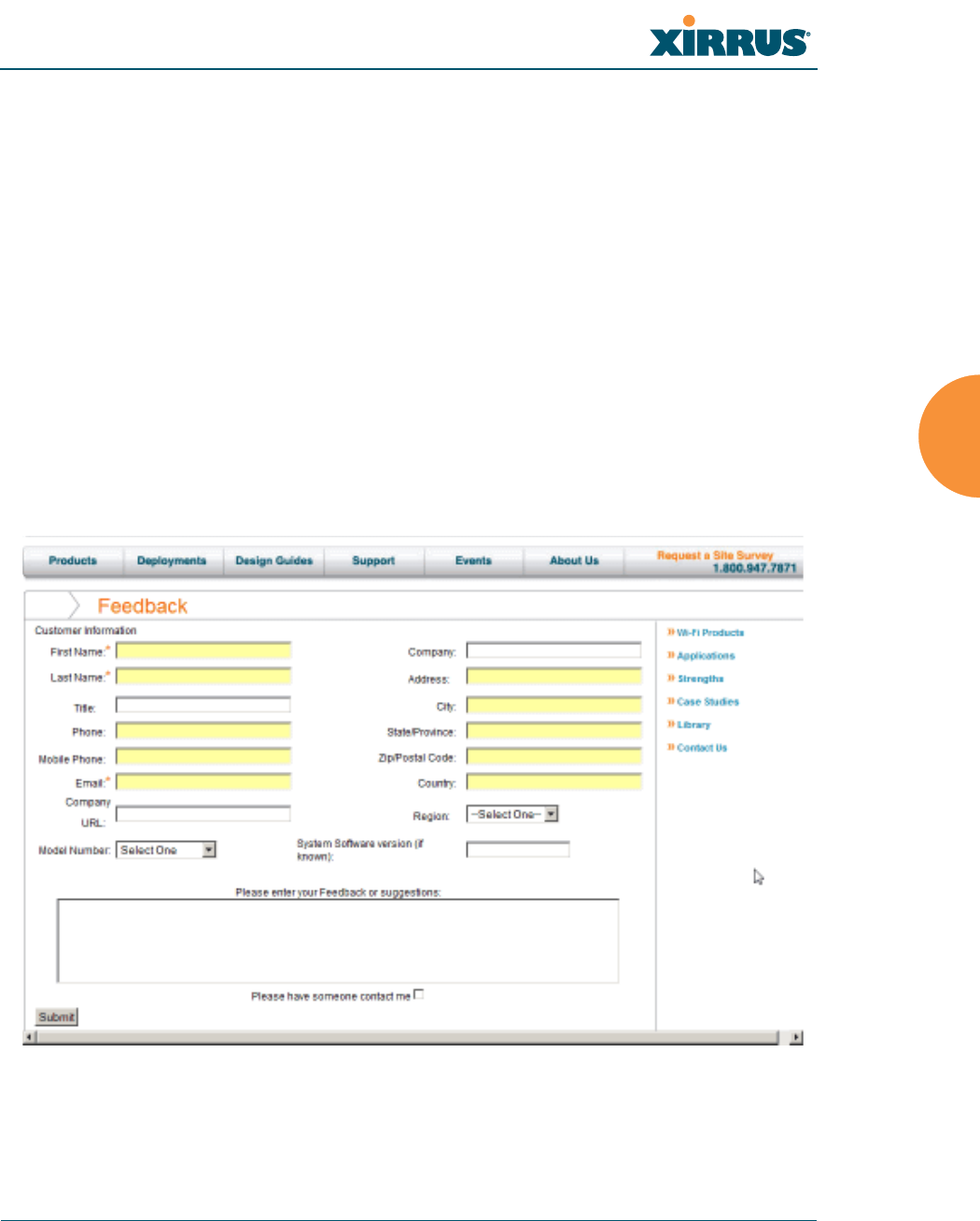
Wi-Fi Array
The Web Management Interface 125
z
Click on the Feedback button to generate a Web page that allows you to
submit your comments to Xirrus, Inc. You can also access the feedback
page at http://www.xirrus.com/public/feedback/. Refer to Figure 63 on
page 125 to see a sample of the feedback form.
z
Click on the Print button to send a print file of the active window to your
local printer.
z
Click on the Help button to access the Array’s online help system.
Submitting Your Comments
When submitting comments via the Feedback button, ensure that you provide as
much detail as possible, including your contact information, the product model
number that the comment relates to, and the ArrayOS software version (if
known). When finished, click on the Submit button to submit your comment.
Figure 63. Feedback Form
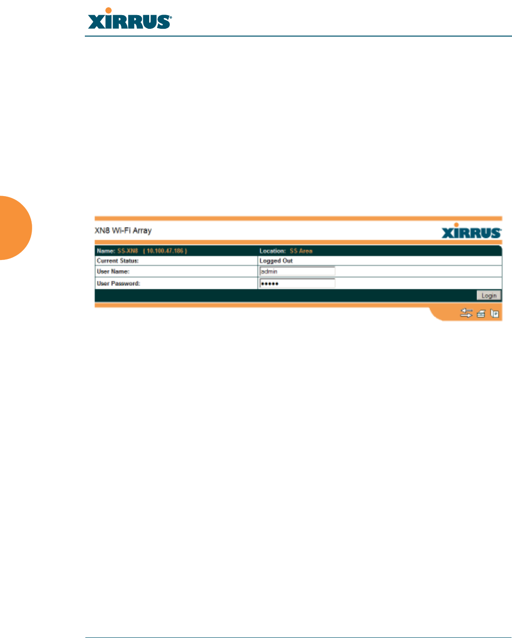
Wi-Fi Array
126 The Web Management Interface
Logging In
Use this procedure to log in to the WMI via your Web browser.
1. Establish a network connection and open your Web browser.
2. Connect to the Wi-Fi Array via its default IP address (10.0.2.1 for both
Gigabit 1 and Gigabit 2 Ethernet ports) or via a DHCP assigned IP
address.
3. To log in to the Array’s Web Management Interface, enter admin when
prompted for a user name and password.
Figure 64. Logging In to the Wi-Fi Array
Applying Configuration Changes
When you have defined all your settings in any WMI configuration window, you
must click on the Apply button for the changes to take effect in the current
session, or click on the Save button to apply changes to this session and write
your changes, so they will be preserved after a reboot.
See Also
Key Features and Benefits
Wi-Fi Array Product Overview

Wi-Fi Array
Viewing Status on the Wi-Fi Array 127
Viewing Status on the Wi-Fi
Array
These windows provide status information and statistics for your Array using the
product’s embedded Web Management Interface (WMI). You cannot make
configuration changes to your Array from these windows. The following topics
have been organized into functional areas that reflect the flow and content of the
Status section of the navigation tree in the left frame of the WMI.
z
“Array Status Windows” on page 127
z
“Network Status Windows” on page 133
z
“RF Monitor Windows” on page 142
z
“Station Status Windows” on page 150
z
“Statistics Windows” on page 165
z
“System Log Window” on page 173
Configuration and Tools windows are not discussed here. For information on
these windows, please see:
z
“Configuring the Wi-Fi Array” on page 175
z
“Using Tools on the Wi-Fi Array” on page 295
Array Status Windows
The following Array Status windows are available:
z
Array Summary—displays information on the configuration of all Array
interfaces, including IAPs.
z
Array Information—provides version/serial number information for all
Array components.
z
Array Configuration—shows all configuration information for the Array
in text format.
z
Admin History—shows all current and past logins since the last reboot.
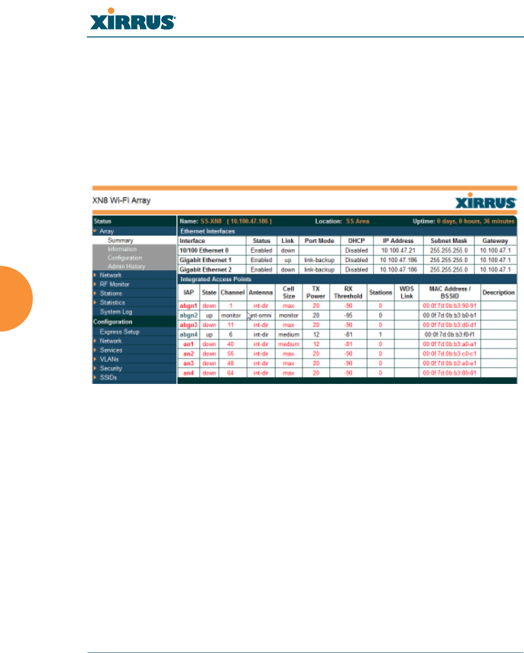
Wi-Fi Array
128 Viewing Status on the Wi-Fi Array
Array Summary
This is a status only window that provides a snapshot of the global configuration
settings for all Wi-Fi Array network interfaces and IAPs. You must go to the
appropriate configuration window to make changes to any of the settings
displayed here—configuration changes cannot be made from this window.
Clicking on an interface or IAP will take you to the proper window for making
configuration changes.
Figure 65. Array Summary
Content of the Array Summary Window
The Array Summary window is sub-divided into the Ethernet Interfaces section
and the Integrated Access Points (radio) section, providing you with the
following information:
z
Ethernet Interfaces Section
This section provides information about network interface devices. To
make configuration changes to these devices, go to “Network Interfaces”
on page 183.
•Interface: Lists the network interfaces that are available on the Array
(10/100 Ethernet 0, Gigabit Ethernet 1 and Gigabit Ethernet 2).
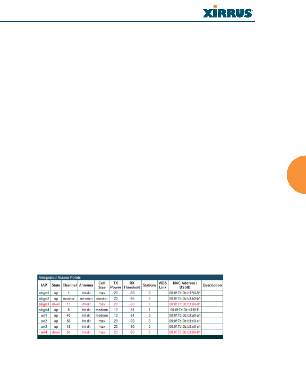
Wi-Fi Array
Viewing Status on the Wi-Fi Array 129
•Status: Shows the current state of each interface, either enabled or
disabled.
•Link: Shows whether the link on this interface is up or down.
•DHCP: Shows whether DHCP on this port is enabled or disabled.
•IP Address: Shows the current IP address assigned to each network
interface device.
•Subnet Mask: Shows the subnet mask, which defines the number of
IP addresses that are available on the routed subnet where the Array
is located.
•Gateway: Shows the IP address of the router that the Array uses to
transmit data to other networks.
z
Integrated Access Points Section
This section provides information about the Integrated Access Points
(IAPs) that are contained within the Array. How many IAPs are listed
depends on which product model you are using (16 IAPs for the XN16,
XS16, or XS-3900, 12 IAPs for the XN12, or XS12, 8 IAPs for the XN8, XS8,
or XS-3700, and 4 IAPs for the XN4, XS4 or XS-3500). To make
configuration changes to these IAPs, go to “IAP Settings” on page 255.
•IAP: Lists the IAPs that are available on the Array.
•State: Shows the current state of each IAP, either up or down. IAPs
that are down are shown in RED. Figure 66 shows an example where
IAP a3 is down.
Figure 66. Disabled IAP (Partial View)

Wi-Fi Array
130 Viewing Status on the Wi-Fi Array
•Channel: Shows which channel each IAP is using, and the channel
setting. To avoid co-channel interference, adjacent radios should not
be using adjacent channels. To make channel selections for a specific
IAP, go to “IAP Settings” on page 255.
•Antenna: Shows which antenna is being used by each IAP.
•Cell Size: Indicates which cell size setting is currently active for each
IAP—small, medium, large, max, automatic, or manually defined by
you. The cell size of an IAP is a function of its transmit power and
determines the IAP’s overall coverage. To define cell sizes, go to “IAP
Settings” on page 255. For additional information about cell sizes and
the importance of planning for and defining the optimum cell sizes
for your Array, go to “Coverage and Capacity Planning” on page 50.
Figure 67. IAP Cells
•Tx Power: Shows the transit power for each IAP.
•Rx Threshold: Shows the receive threshold for each IAP.
•Stations: Informs you how many client stations are currently
associated with each IAP. All Arrays can handle up to 64 concurrent
users per individual IAP, thus 16-port models can handle 1024 users
per Array.
•WDS Link: The WDS Link on this radio (if any). See “WDS” on
page 285.
•MAC Address/BSSID: Shows the MAC address for each IAP.