Cambium Networks XN8 Wireless LAN Array User Manual XN PDF
Xirrus, Inc. Wireless LAN Array XN PDF
UserManual.wiki
>
Cambium Networks
>
XN8 User Manual
>
Users Manual 5of5
Contents
1.
Users Manual pt1of5
2.
Users Manual pt2of5
3.
Users Manual pt3of5
4.
Users Manual pt4of5
5.
Users Manual pt5of5
6.
Users Manual 1of5
7.
Users Manual 2of5
8.
Users Manual 3of5
9.
Users Manual 4of5
10.
Users Manual 5of5
11.
XN Guide small 1 of 5 revised
Users Manual 5of5
Navigation menu
Upload a User Manual
Namespaces
Wiki Guide
HTML
PDF
Info
Views
User Manual
Discussion / Help
Navigation
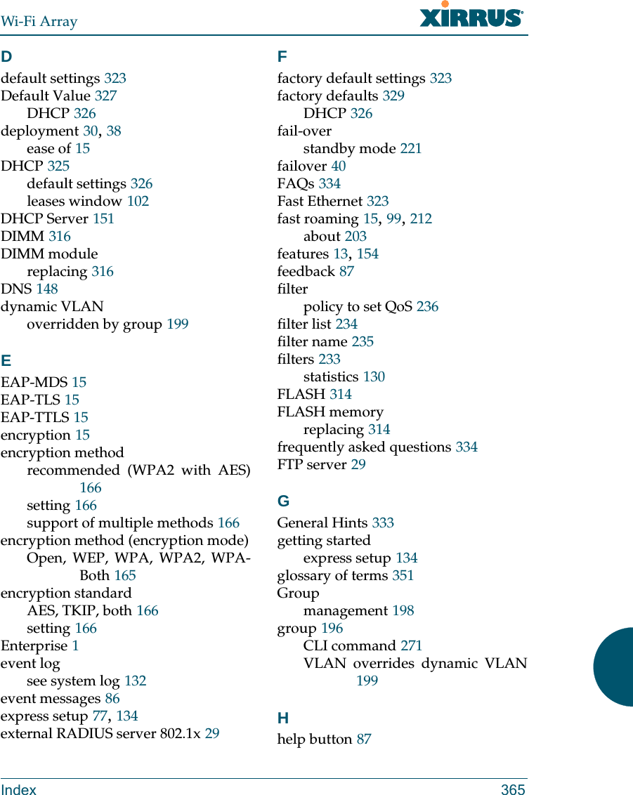
![Wi-Fi ArrayThe Command Line Interface 271group The group command [Xirrus_Wi-Fi_Array(config)# group] is used to create and configure user groups. User groups allow administrators to assign specific network parameters to users through RADIUS privileges rather than having to map users to a specific SSID. Groups provide flexible control over user privileges without the need to create large numbers of SSIDs. For more information, see “Groups” on page 196. hostname The hostname command [Xirrus_Wi-Fi_Array(config)# hostname] is used to change the hostname used by the Array.Command Descriptionadd Create a new user group. FORMAT:group add [group-name]del Delete a user group.FORMAT:group del [group-name]edit Set parameters values for a group. FORMAT:group edit [group-name]reset Reset the group.FORMAT:group resetCommand Descriptionhostname Change the hostname of the Array.FORMAT:hostname [name]](https://usermanual.wiki/Cambium-Networks/XN8.Users-Manual-5of5/User-Guide-962098-Page-2.png)
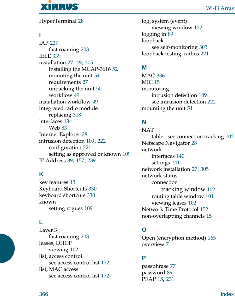
![Wi-Fi Array272 The Command Line Interfacehttps The https command [Xirrus_Wi-Fi_Array(config)# https] is used to enable or disable the Web Management Interface (https), which is enabled by default. It also allows you to establish a timeout for your Web management session.Command Descriptiondisable Disable the https feature.FORMAT:https disableenable Enable the https feature.FORMAT:https enableoff Disable the https feature.FORMAT:https offon Enable the https feature.FORMAT:https ontimeout Define an elapsed period (in seconds) after which the Web Management Interface will time out.FORMAT:https timeout 5000](https://usermanual.wiki/Cambium-Networks/XN8.Users-Manual-5of5/User-Guide-962098-Page-3.png)
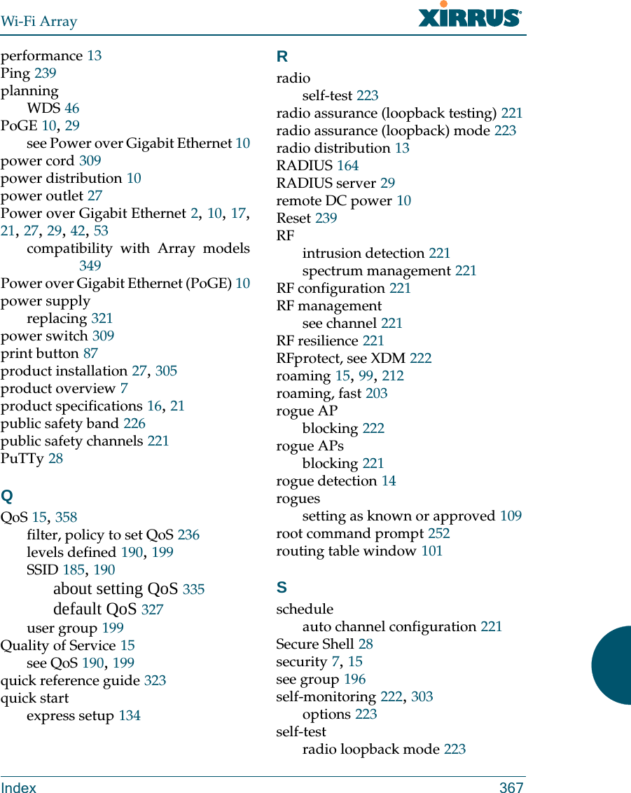
![Wi-Fi ArrayThe Command Line Interface 273interface The interface command [Xirrus_Wi-Fi_Array(config)# interface] is used to select the interface that you want to configure. To see a listing of the commands that are available for each interface, use the ? command at the selected interface prompt. For example, using the ? command at the Xirrus_Wi-Fi_Array(config-gig1}#prompt displays a listing of all commands for the gig1 interface.Command Descriptionconsole Select the console interface. The console interface is used for management purposes only.FORMAT:interface consoleeth0 Select the Fast Ethernet interface. The Fast Ethernet interface is used for management purposes only.FORMAT:interface eth0Note: To configure a static route for management traffic, next enter:static-route addr [ip-addr]static-route mask [subnet-mask]gig1 Select the Gigabit 1 interface.FORMAT:interface gig1gig2 Select the Gigabit 2 interface.FORMAT:interface gig2iap Select an IAP.FORMAT:interface iap](https://usermanual.wiki/Cambium-Networks/XN8.Users-Manual-5of5/User-Guide-962098-Page-4.png)
![Wi-Fi Array274 The Command Line Interfaceload The load command [Xirrus_Wi-Fi_Array(config)# load] loads a configuration file.location The location command [Xirrus_Wi-Fi_Array(config)# location] is used to set the location for the Array.Command Descriptionfactory.conf Load the factory settings configuration file. FORMAT:load [factory.conf]lastboot.conf Load the configuration file from the last boot-up. FORMAT:load [lastboot.conf][myfile].conf If you have saved a configuration, enter its name to load it. FORMAT:load [myfile.conf]saved.conf Load the configuration file with the last saved settings. FORMAT:load [saved.conf]Command Description<cr> Set the location for the Array.FORMAT:location [newlocation]When you enter the location, simply hit the Enter key <cr> to input the new location.](https://usermanual.wiki/Cambium-Networks/XN8.Users-Manual-5of5/User-Guide-962098-Page-5.png)
![Wi-Fi ArrayThe Command Line Interface 275management The management command [Xirrus_Wi-Fi_Array(config)# management] enters management mode, where you may configure console management parameters.more The more command [Xirrus_Wi-Fi_Array(config)# more] is used to turn terminal pagination ON or OFF.Command Description<cr> Enter management mode.FORMAT:management <cr>Command Descriptionoff Turn OFF terminal pagination.FORMAT:more offon Turn ON terminal pagination.FORMAT:more on](https://usermanual.wiki/Cambium-Networks/XN8.Users-Manual-5of5/User-Guide-962098-Page-6.png)
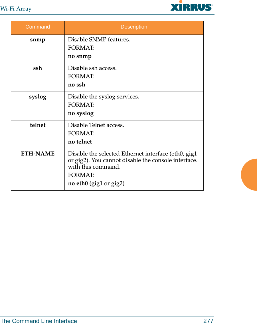
![Wi-Fi Array276 The Command Line Interfaceno The no command [Xirrus_Wi-Fi_Array(config)# no] is used to disable a selected element or set the element to its default value.Command Descriptionacl Disable the Access Control List.FORMAT:no acldot11a Disable all 802.11an IAPs (radios).FORMAT:no dot11adot11bg Disable all 802.11bg IAPs (radios).FORMAT:no dot11bghttps Disable https access.FORMAT:no httpsintrude-detect Disable intrusion detection.FORMAT:no intrude-detectmanagement Disable management on all Ethernet interfaces.FORMAT:no managementmore Disable terminal pagination.FORMAT:no morentp Disable the NTP server.FORMAT:no ntp](https://usermanual.wiki/Cambium-Networks/XN8.Users-Manual-5of5/User-Guide-962098-Page-7.png)
![Wi-Fi Array278 The Command Line Interfacequit The quit command [Xirrus_Wi-Fi_Array(config)# quit] is used to exit the Command Line Interface.radius-server The radius-server command [Xirrus_Wi-Fi_Array(config-radius-server)#] is used to configure the external and internal RADIUS server parameters.Command Description<cr> Exit the Command Line Interface.FORMAT:quitIf you have made any configuration changes and your changes have not been saved, you are prompted to save your changes to Flash.At the prompt, answer Yes to save your changes, or answer No to discard your changes.Command Descriptionexternal Configure the external RADIUS server.FORMAT:radius-server externalTo configure the RADIUS accounting server (primary or secondary, and the reporting interval) use:radius-server external accountinginternal Configure the external RADIUS server.FORMAT:radius-server internaluse Choose the active RADIUS server (either external or internal).FORMAT:use external (or internal)](https://usermanual.wiki/Cambium-Networks/XN8.Users-Manual-5of5/User-Guide-962098-Page-9.png)
![Wi-Fi ArrayThe Command Line Interface 279reboot The reboot command [Xirrus_Wi-Fi_Array(config)# reboot] is used to reboot the Array. If you have unsaved changes, the command will notify you and give you a chance to cancel the reboot. reset The reset command [Xirrus_Wi-Fi_Array(config)# reset] is used to reset all settings to their default values then reboot the Array.Command Description<cr> Reboot the Array.FORMAT:rebootdelay Reboot the Array after a delay of 1 to 60 seconds.FORMAT:reboot delay [n]Command Description<cr> Reset all configuration parameters to their factory default values.FORMAT:resetThe Array is rebooted automatically.preserve-ip-settingsPreserve all ethernet and VLAN settings and reset all other configuration parameters to their factory default values.FORMAT:reset preserve-ip-settingsThe Array is rebooted automatically.](https://usermanual.wiki/Cambium-Networks/XN8.Users-Manual-5of5/User-Guide-962098-Page-10.png)
![Wi-Fi Array280 The Command Line Interfacerun-tests The run-tests command [Xirrus_Wi-Fi_Array(run-tests)#] is used to enter run-tests mode, which allows you to perform a range of tests on the Array.Command Description<cr> Enter run-tests mode.FORMAT:run-tests iperf Execute iperf utility.FORMAT:run-tests iperfkill-beacons Turn off beacons for selected single IAP.FORMAT:run-tests kill-beacons [off | iap-name] kill-probe-responses Turn off probe responses for selected single IAP.FORMAT:run-tests kill-probe-responses [off | iap-name] led LED test.FORMAT:run-tests led [flash | rotate] memtest Execute memory tests.FORMAT:run-tests memtestping Execute ping utility.FORMAT:run-tests ping [host-name | ip-addr] rlb Run manufacturing radio loopback test.FORMAT:run-tests rlb {optional command line switches]](https://usermanual.wiki/Cambium-Networks/XN8.Users-Manual-5of5/User-Guide-962098-Page-11.png)
![Wi-Fi ArrayThe Command Line Interface 281self-test Execute self-test.FORMAT:run-tests self-test {logfile-name (optional)]site-survey Enable or disable site survey mode.FORMAT:run-tests site-survey [on | off | enable | disable] ssh Execute ssh utility.FORMAT:run-tests ssh [hostname | ip-addr] [command-line-switches (optional)] tcpdump Execute tcpdump utility to dump traffic for selected interface or VLAN. FORMAT:run-tests tcpdumptelnet Execute telnet utility.FORMAT:run-tests telnet [hostname | ip-addr] [command-line-switches (optional)] traceroute Execute traceroute utility.FORMAT:run-tests traceroute [host-name | ip-addr]Command Description](https://usermanual.wiki/Cambium-Networks/XN8.Users-Manual-5of5/User-Guide-962098-Page-12.png)
![Wi-Fi Array282 The Command Line Interfacesecurity The security command [Xirrus_Wi-Fi_Array(config-security)#] is used to establish the security parameters for the Array.Command Descriptionwep Set the WEP encryption parameters.FORMAT:security wepwpa Set the WEP encryption parameters.FORMAT:security wpa](https://usermanual.wiki/Cambium-Networks/XN8.Users-Manual-5of5/User-Guide-962098-Page-13.png)
![Wi-Fi ArrayThe Command Line Interface 283snmp The snmp command [Xirrus_Wi-Fi_Array(config-snmp)#] is used to enable, disable, or configure SNMP.Command Descriptioncommunity Set the SNMP read-only or read-write community string.FORMAT:snmp community [newcommunity]disable Disable SNMP.FORMAT:snmp disableenable Enable SNMP.FORMAT:snmp enableno Disable the selected feature.FORMAT:snmp no [feature]off Disable SNMP.FORMAT:snmp offon Enable SNMP.FORMAT:snmp ontrap-auth Send traps for authentication failures.FORMAT:snmp trap-auth [trap]trap-host[1-4] Set the SNMP trap IP address or host name. Up to four trap hosts may be set, one at a time.FORMAT:snmp trap-host 1.2.3.4](https://usermanual.wiki/Cambium-Networks/XN8.Users-Manual-5of5/User-Guide-962098-Page-14.png)
![Wi-Fi Array284 The Command Line Interfacessh The ssh command [Xirrus_Wi-Fi_Array(config)# ssh] is used to enable or disable the SSH feature.trap-port[1-4] Set the SNMP trap port.FORMAT:snmp trap-port 240Command Descriptiondisable Disable SSH.FORMAT:ssh disableenable Enable SSH.FORMAT:ssh enableoff Disable SSH.FORMAT:ssh offon Enable SSH.FORMAT:ssh ontimeout Set the SSH inactivity timeout.FORMAT:ssh timeout 300 (in seconds)Command Description](https://usermanual.wiki/Cambium-Networks/XN8.Users-Manual-5of5/User-Guide-962098-Page-15.png)
![Wi-Fi ArrayThe Command Line Interface 285ssid The ssid command [Xirrus_Wi-Fi_Array(config-ssid)#] is used to establish your SSID parameters.standby The standby command [Xirrus_Wi-Fi_Array(config-ssid)#] sets this Array to function as a standby unit for another Array.Command Descriptionadd Add an SSID.FORMAT:ssid add [newssid]del Delete an SSID.FORMAT:ssid del [oldssid]edit Edit an existing SSID.FORMAT:ssid edit [existingssid]reset Delete all SSIDs and restore the default SSID.FORMAT:ssid resetCommand Descriptionmode Enable or disable standby mode on this Array.FORMAT:standby mode [disable|enable|off|on]target Specify the MAC address of the target Array to be monitored for failure.FORMAT:standby target [AA:BB:CC:DD:EE:FF]](https://usermanual.wiki/Cambium-Networks/XN8.Users-Manual-5of5/User-Guide-962098-Page-16.png)
![Wi-Fi Array286 The Command Line Interfacesyslog The syslog command [Xirrus_Wi-Fi_Array(config-syslog)#] is used to enable, disable, or configure the Syslog server.Command Descriptionconsole Enable or disable the display of Syslog messages on the console, and set the level to be displayed. All messages at this level and lower (i.e., more severe) will be displayed.FORMAT:syslog console [on/off] level [0-7]disable Disable the Syslog server.FORMAT:syslog disableemail Disable the Syslog server.FORMAT:syslog email from [email-from-address] level [0-7] password [email-acct-password] server [email-server-IPaddr] test [test-msg-text] to-list [recipient-email-addresses] user [email-acct-username]enable Enable the Syslog server.FORMAT:syslog enablelocal-file Set the size and/or severity level (all messages at this level and lower will be logged).FORMAT:syslog local-file size [1-500] level [0-7]no Disable the selected feature.FORMAT:syslog no [feature]](https://usermanual.wiki/Cambium-Networks/XN8.Users-Manual-5of5/User-Guide-962098-Page-17.png)
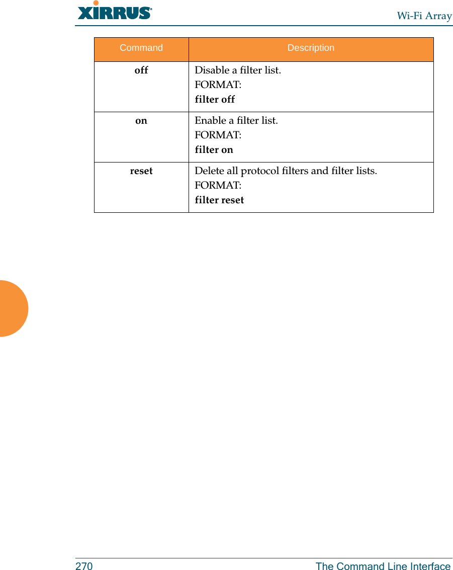
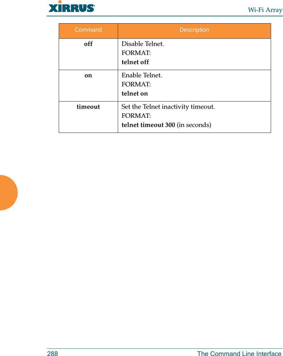
![Wi-Fi ArrayThe Command Line Interface 287telnet The telnet command [Xirrus_Wi-Fi_Array(config)# telnet] is used to enable or disable Telnet.off Disable the Syslog server.FORMAT:syslog offon Enable the Syslog server.FORMAT:syslog onprimary Set the IP address of the primary Syslog server and/or the severity level of messages to be logged.FORMAT:syslog primary [1.2.3.4] level [0-7]secondary Set the IP address of the secondary (backup) Syslog server and/or the severity level of messages to be logged.FORMAT:syslog primary [1.2.3.4] level [0-7]Command Descriptiondisable Disable Telnet.FORMAT:telnet disableenable Enable Telnet.FORMAT:telnet enableCommand Description](https://usermanual.wiki/Cambium-Networks/XN8.Users-Manual-5of5/User-Guide-962098-Page-18.png)
![Wi-Fi ArrayThe Command Line Interface 289uptime The uptime command [Xirrus_Wi-Fi_Array(config)# uptime] is used to display the elapsed time since you last rebooted the Array. vlan The vlan command [Xirrus_Wi-Fi_Array(config-vlan)#] is used to establish your VLAN parameters.Command Description<cr> Display time since last reboot.FORMAT:uptimeCommand Descriptionadd Add a VLAN.FORMAT:vlan add [newvlan]default-route Assign a VLAN for the default route (for outbound management traffic).FORMAT:vlan default-route [defaultroute]delete Delete a VLAN.FORMAT:vlan delete [oldvlan]edit Modify an existing VLAN.FORMAT:vlan edit [existingvlan]native-vlan Assign a native VLAN (traffic is untagged).FORMAT:vlan native-vlan [nativevlan]](https://usermanual.wiki/Cambium-Networks/XN8.Users-Manual-5of5/User-Guide-962098-Page-20.png)
![Wi-Fi Array290 The Command Line Interfaceno Disable the selected feature.FORMAT:vlan no [feature]reset Delete all existing VLANs.FORMAT:vlan resetCommand Description](https://usermanual.wiki/Cambium-Networks/XN8.Users-Manual-5of5/User-Guide-962098-Page-21.png)


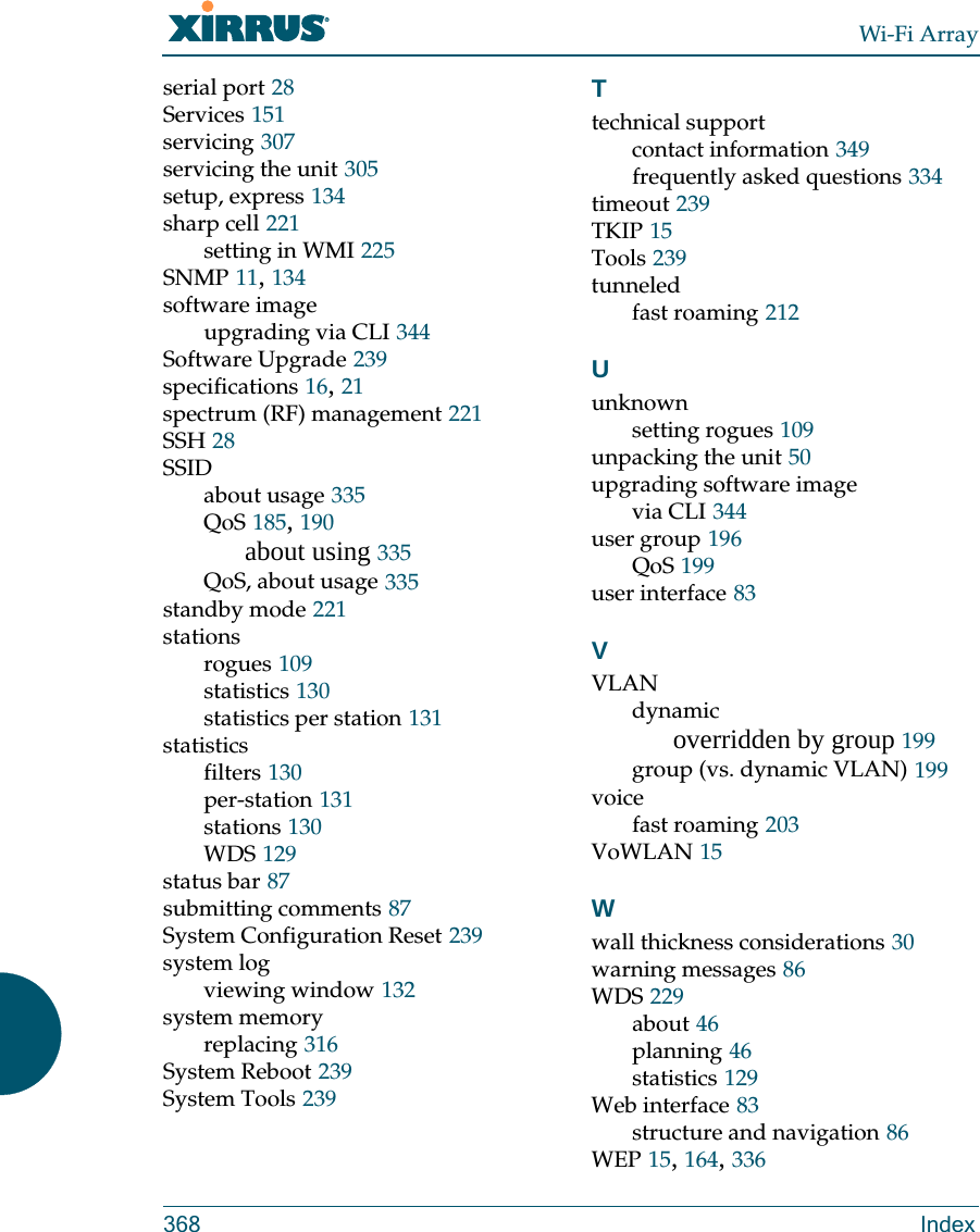
![Wi-Fi ArrayAppendix C: Technical Support 345Boot your Array and watch the progress messages. When Press space bar to exit to bootloader: is displayed, press the space bar. The rest of this procedure is performed using the bootloader. The following steps assume that you are running DHCP on your local network. 5. Type dhcp and hit return. This instructs the Array to obtain a DHCP address and use it during this boot in the bootloader environment. 6. Type dir and hit return to see what's currently in the compact flash. 7. Type del and hit return to delete the contents of the compact flash. 8. Type update server <TFTP-server-ip-addr> xs-3.x-xxxx.bin (the actual Xirrus file name will vary depending on Array model number and software version—use the file name from your software update) and hit return. The software update will be transferred to the Array's memory and will be written to the it’s compact flash card. (See output below.)9. Type reset and hit return. Your Array will reboot, running your new version of software. Sample Output for the Upgrade Procedure:The user actions are highlighted in the output below, for clarity.Username: adminPassword: *****Xirrus-WiFi-Array# configureXirrus-WiFi-Array(config)# rebootAre you sure you want to reboot? [yes/no]: yesArray is being rebooted.Xirrus Boot Loader 1.0.0 (Oct 17 2006 - 13:11:42), Build: 2725Processor | Motorola PowerPC, PVR=80200020 SVR=80300020Board | Xirrus MPC8540 CPU BoardClocks | CPU : 825 MHz DDR : 330 MHz Local Bus: 41 MHz](https://usermanual.wiki/Cambium-Networks/XN8.Users-Manual-5of5/User-Guide-962098-Page-76.png)
![Wi-Fi Array346 Appendix C: Technical SupportL1 cache | Data: 32 KB Inst: 32 KB Status : EnabledWatchdog | Enabled (5 secs)I2C Bus | 400 KHzDTT | CPU:34C RF0:34C RF1:34C RF2:27C RF3:29CRTC | Wed 2007-Nov-05 6:43:14 GMTSystem DDR | 256 MB, Unbuffered Non-ECC (2T)L2 cache | 256 KB, EnabledFLASH | 4 MB, CRC: OKFPGA | 2 Devices programmedPacket DDR | 256 MB, Unbuffered Non-ECC, EnabledNetwork | Mot FEC Mot TSEC1 [Primary] Mot TSEC2IDE Bus 0 | OKCFCard | 122 MB, Model: Hitachi XXM2.3.0Environment| 4 KB, InitializedIn: serialOut: serialErr: serialPress space bar to exit to bootloader: XBL>dhcp[DHCP ] Device : Mot TSEC1 1000BT Full Duplex[DHCP ] IP Addr : 192.168.39.195XBL>dir[CFCard] Directory of / Date Time Size File or Directory name----------- -------- -------- ---------------------------2007-Nov-05 6:01:56 29 lastboot2007-Apr-05 15:47:46 28210390 xs-3.1-0433.bak2007-Mar-01 16:39:42 storage/2007-Apr-05 15:56:38 28210430 xs-3.1-0440.bin2007-Mar-03 0:56:28 wpr/3 file(s), 2 dir(s)](https://usermanual.wiki/Cambium-Networks/XN8.Users-Manual-5of5/User-Guide-962098-Page-77.png)
![Wi-Fi ArrayAppendix C: Technical Support 347XBL>del * [CFCard] Delete : 2 file(s) deletedXBL>update server 192.168.39.102 xs-3.0-0425.bin[TFTP ] Device : Mot TSEC1 1000BT Full Duplex[TFTP ] Client : 192.168.39.195[TFTP ] Server : 192.168.39.102[TFTP ] File : xs-3.0-0425.bin[TFTP ] Address : 0x1000000[TFTP ] Loading : ##################################################[TFTP ] Loading : ##################################################[TFTP ] Loading : ###### done[TFTP ] Complete: 12.9 sec, 2.1 MB/sec[TFTP ] Bytes : 27752465 (1a77811 hex)[CFCard] File : xs-3.0-0425.bin[CFCard] Address : 0x1000000[CFCard] Saving : ############################################### done[CFCard] Complete: 137.4 sec, 197.2 KB/sec[CFCard] Bytes : 27752465 (1a77811 hex)XBL>reset[RESET ]Xirrus Boot Loader 1.0.0 (Oct 17 2006 - 13:11:42), Build: 2725Processor | Motorola PowerPC, PVR=80200020 SVR=80300020Board | Xirrus MPC8540 CPU BoardClocks | CPU : 825 MHz DDR : 330 MHz Local Bus: 41 MHzL1 cache | Data: 32 KB Inst: 32 KB Status : EnabledWatchdog | Enabled (5 secs)I2C Bus | 400 KHzDTT | CPU:33C RF0:32C RF1:31C RF2:26C RF3:27CRTC | Wed 2007-Nov-05 6:48:44 GMTSystem DDR | 256 MB, Unbuffered Non-ECC (2T)](https://usermanual.wiki/Cambium-Networks/XN8.Users-Manual-5of5/User-Guide-962098-Page-78.png)
![Wi-Fi Array348 Appendix C: Technical SupportL2 cache | 256 KB, EnabledFLASH | 4 MB, CRC: OKFPGA | 2 Devices programmedPacket DDR | 256 MB, Unbuffered Non-ECC, EnabledNetwork | Mot FEC Mot TSEC1 [Primary] Mot TSEC2IDE Bus 0 | OKCFCard | 122 MB, Model: Hitachi XXM2.3.0Environment| 4 KB, InitializedIn: serialOut: serialErr: serialPress space bar to exit to bootloader: [CFCard] File : xs*.bin[CFCard] Address : 0x1000000[CFCard] Loading : ############################################### done[CFCard] Complete: 26.9 sec, 1.0 MB/sec[CFCard] Bytes : 27752465 (1a77811 hex)[Boot ] Address : 0x01000000[Boot ] Image : Verifying checksum .... OK[Boot ] Unzip : Multi-File Image .... OK[Boot ] Initrd : Loading RAMDisk Image[Boot ] Initrd : Verifying checksum .... OK[Boot ] Execute : Transferring control to OSInitializing hardware ........................................ OKXirrus Wi-Fi ArrayArrayOS Version 3.0-425Copyright (c) 2005-2007 Xirrus, Inc.http://www.xirrus.comUsername:](https://usermanual.wiki/Cambium-Networks/XN8.Users-Manual-5of5/User-Guide-962098-Page-79.png)