Cambium Networks XR520 Xirrus Wireless Array User Manual xirrus PDF
Xirrus, Inc. Xirrus Wireless Array xirrus PDF
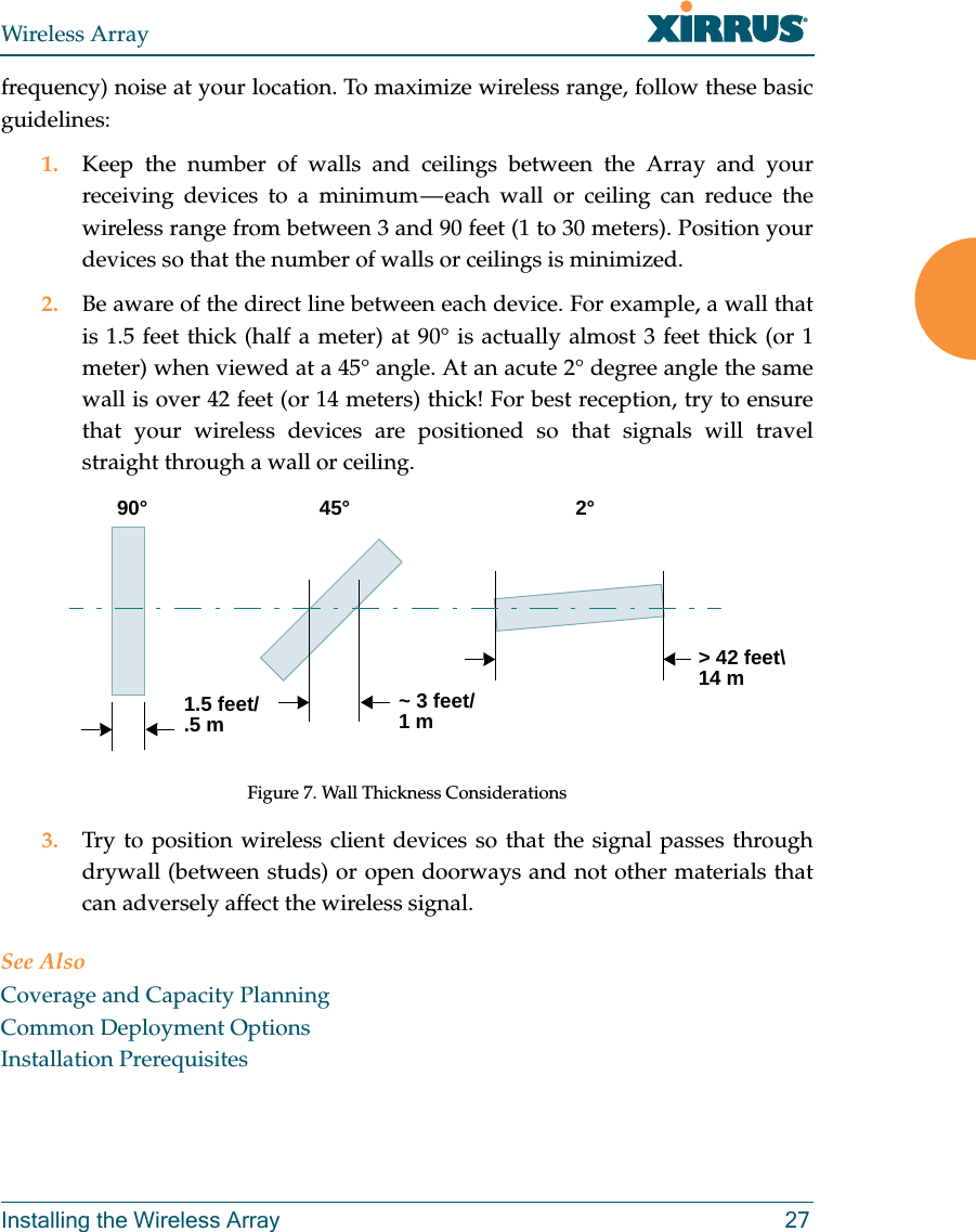
UserManual.wiki
>
Cambium Networks
>
XR520 User Manual
>
User manual 1 rev
Contents
1.
User Manual Part 1
2.
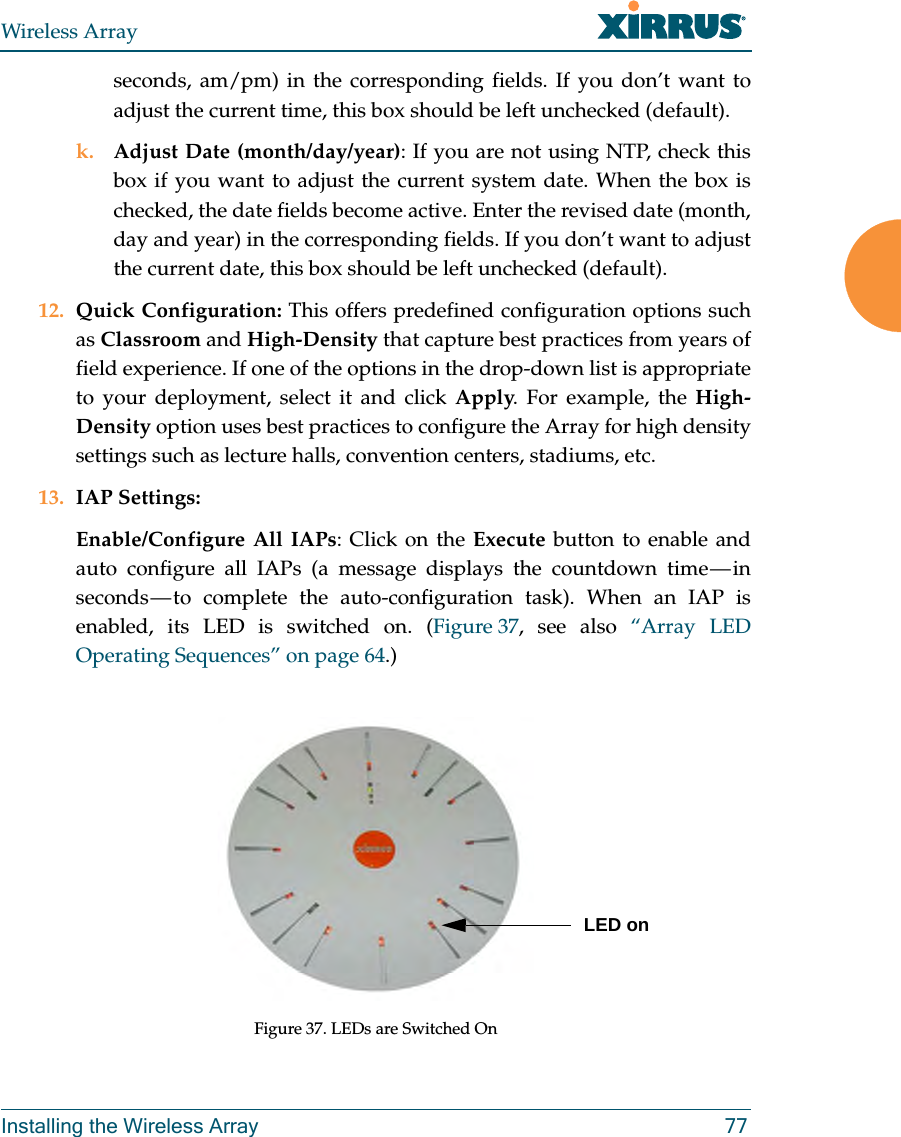
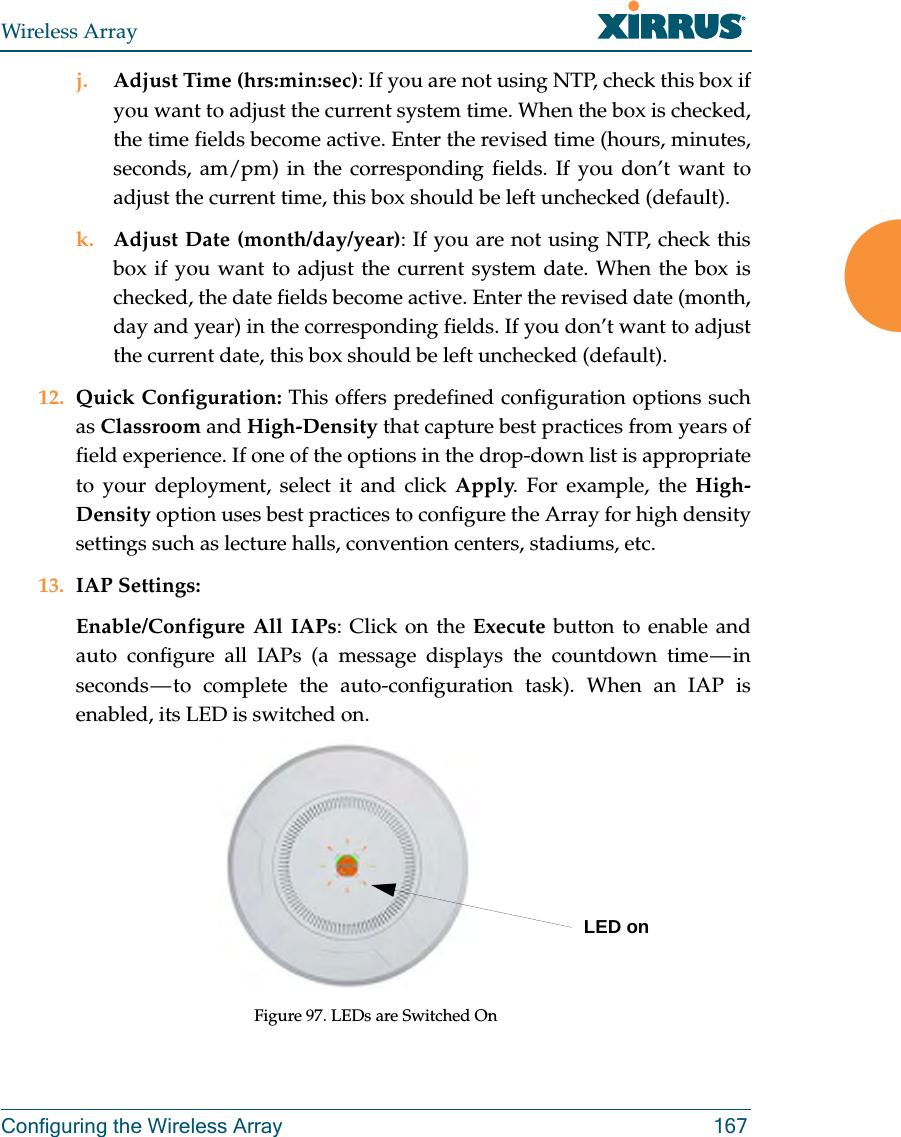
User Manual Part 2
3.
User Manual Part 3
4.
User Manual Part 4
5.
User manual (statement) rev
6.
User manual 1 rev
7.
User manual 2 rev
User manual 1 rev
Navigation menu
Upload a User Manual
Namespaces
Wiki Guide
HTML
PDF
Info
Views
User Manual
Discussion / Help
Navigation
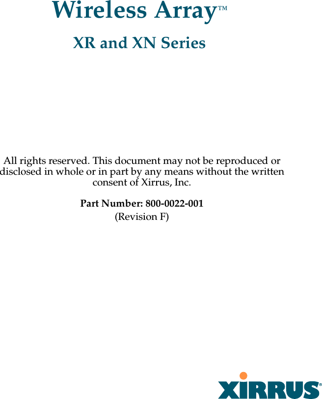


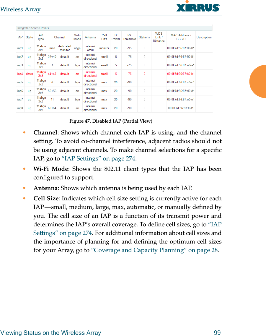
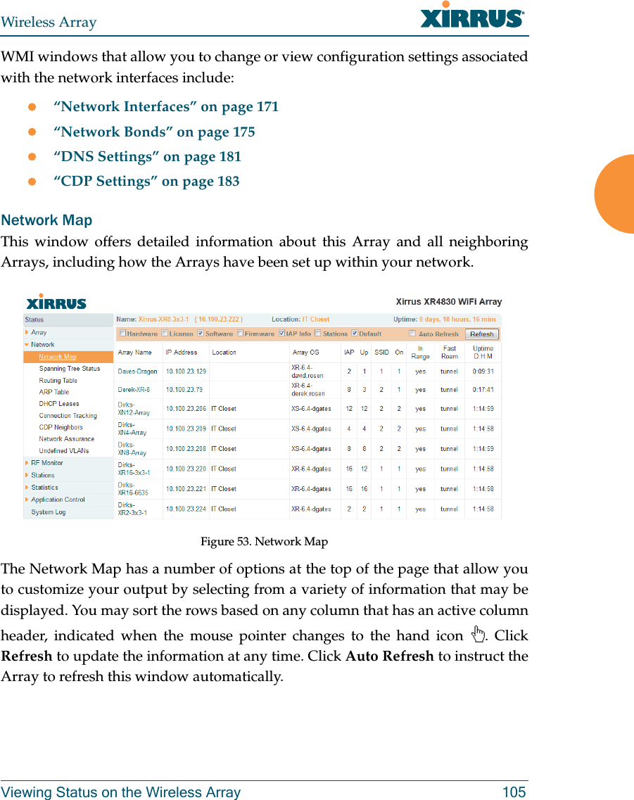
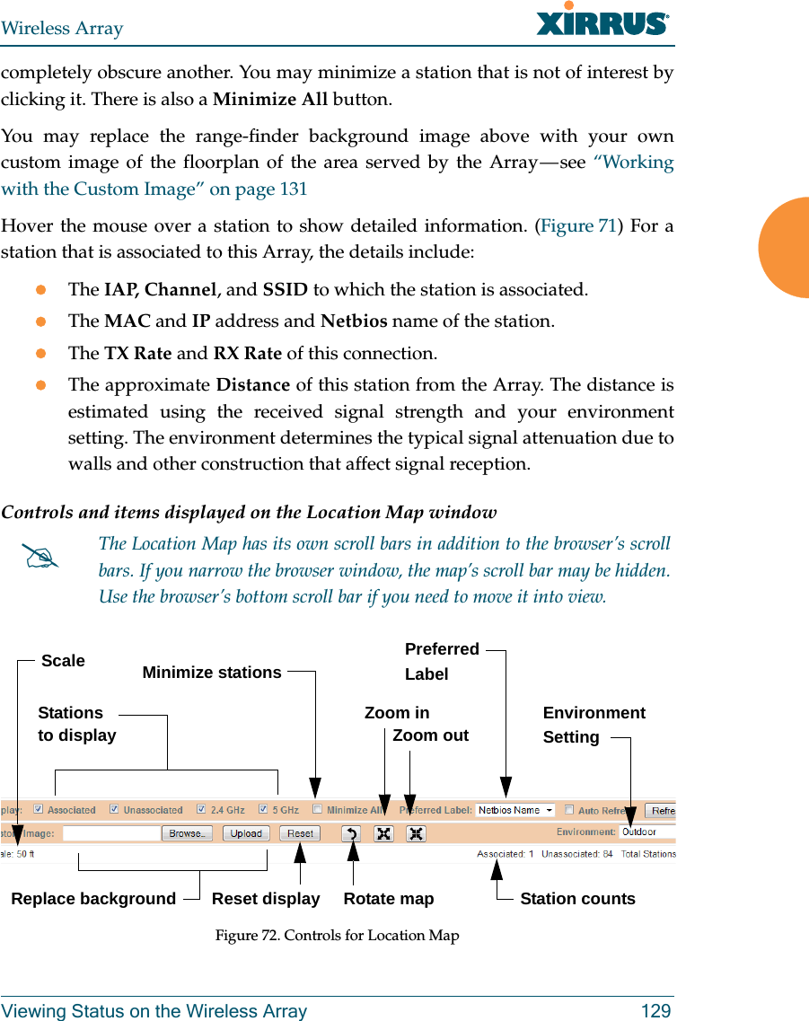
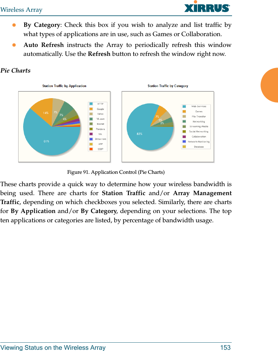
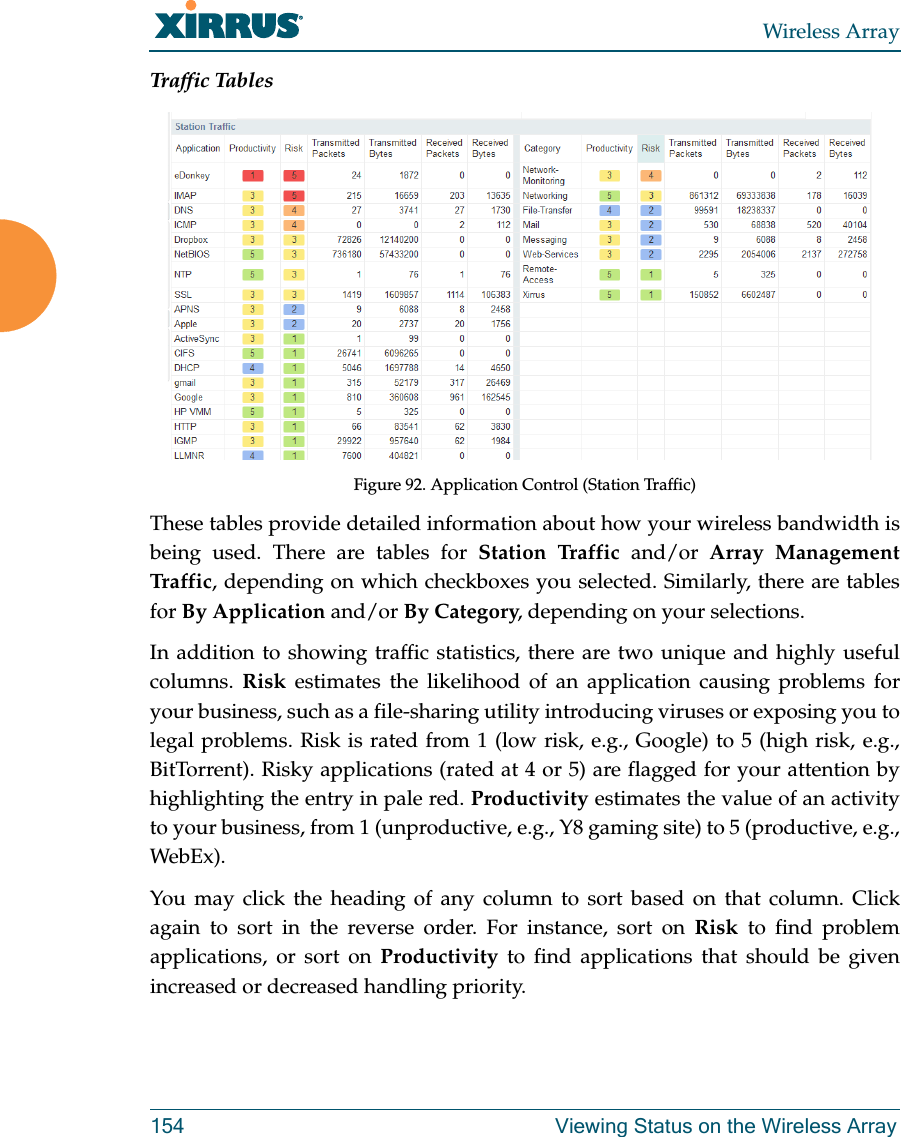
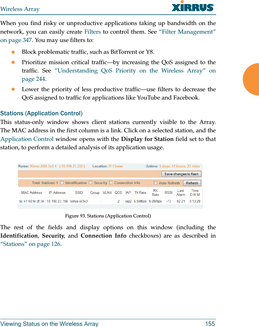
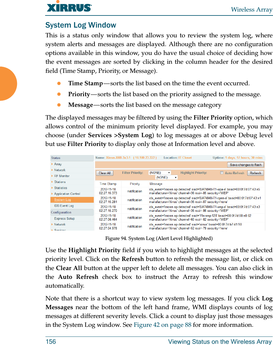

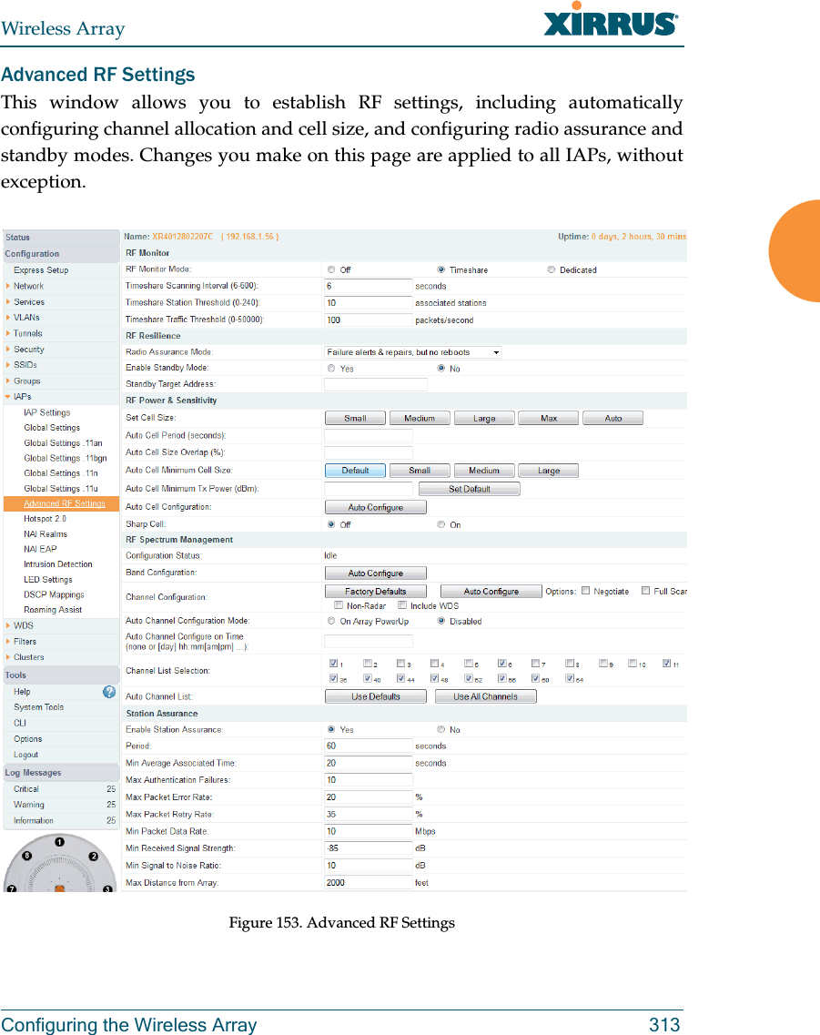

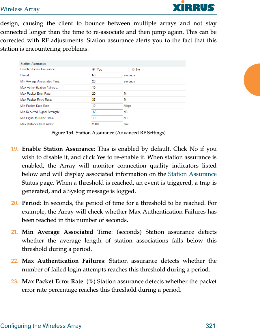
![Wireless Array320 Configuring the Wireless Array15. Auto Channel Configuration Mode: This option allows you to instruct the Array to auto-configure channel selection for each enabled IAP when the Array is powered up. Choose On Array PowerUp to enable this feature, or choose Disabled to disable this feature.16. Auto Channel Configure on Time: This option allows you to instruct the Array to auto-configure channel selection for each enabled IAP at a time you specify here. Leave this field blank unless you want to specify a time at which the auto-configuration utility is initiated. Time is specified in hours and minutes, using the format: [day]hh:mm [am|pm]. If you omit the optional day specification, channel configuration will run daily at the specified time. If you do not specify am or pm, time is interpreted in 24-hour military time. For example, Sat 11:00 pm and Saturday 23:00 are both acceptable and specify the same time. 17. Channel List Selection: This list selects which channels are available to the auto channel algorithm. Channels that are not checked are left out of the auto channel selection process. Note that channels that have been locked by the user are also not available to the auto channel algorithm.18. Auto Channel List: Use All Channels selects all available channels (this does not include locked channels). Use Defaults sets the auto channel list back to the defaults. This omits newer channels (100-140) — many wireless NICs don’t support these channels. Station AssuranceStation assurance monitors the quality of the connections that users are experiencing on the wireless network. You can quickly detect stations that are having problems and take steps to correct them. Use these settings to establish threshold values for errors and other problems. Station assurance is enabled by default, with a set of useful default thresholds that you may adjust as desired.When a connection is experiencing problems and reaches one of these thresholds in the specified period of time, the Array responds with several actions: an event is triggered, a trap is generated, and a Syslog message is logged. For example, if a client falls below the threshold for Min Average Associated Time, this “bouncing” behavior might indicate roaming problems with the network’s RF](https://usermanual.wiki/Cambium-Networks/XR520.User-manual-1-rev/User-Guide-2011403-Page-341.png)