Cambium Networks XR520 Xirrus Wireless Array User Manual xirrus PDF
Xirrus, Inc. Xirrus Wireless Array xirrus PDF
Contents
User manual 1 rev

Wireless Arrays
XR and XN Series
February 7, 2013
Release 6.4

All rights reserved. This document may not be reproduced or
disclosed in whole or in part by any means without the written
consent of Xirrus, Inc.
Part Number: 800-0022-001
(Revision F)
Wireless Array™
XR and XN Series

Trademarks
is a registered trademark of Xirrus, Inc. All other trademarks and brand
names are marks of their respective holders.
Please see Legal Notices, Warnings, Compliance Statements, and Warranty and
License Agreements in “Appendix C: Notices” on page 471.
Xirrus, Inc.
2101 Corporate Center Drive
Thousand Oaks, CA 91320
USA
Tel: 1.805.262.1600
1.800.947.7871 Toll Free in the US
Fax: 1.866.462.3980
www.xirrus.com

Wireless Array
i
Table of Contents
List of Figures.................................................................................... xiii
Introduction ......................................................................................... 1
The Xirrus Family of Products ............................................................................... 1
Nomenclature .................................................................................................... 2
Why Choose the Xirrus Wireless Array? .............................................................. 3
Wireless Array Product Overview ........................................................................ 5
XR Wireless Array Product Family ................................................................ 6
XR500 Series Arrays .................................................................................. 6
XR-1000 and XR-2000 Series Arrays ....................................................... 6
XR-4000 Series Arrays ............................................................................... 8
XR-6000 Series Arrays ............................................................................... 9
XN Wireless Array Product Family ............................................................. 10
XN Family of Arrays ............................................................................... 10
Enterprise Class Security ............................................................................... 11
Deployment Flexibility .................................................................................. 11
Power over Gigabit Ethernet (PoGE) .................................................... 12
Enterprise Class Management ...................................................................... 13
Key Features and Benefits ..................................................................................... 14
High Capacity and High Performance ........................................................ 14
Extended Coverage ......................................................................................... 15
Non-Overlapping Channels .......................................................................... 15
SDMA Optimization ...................................................................................... 15
Fast Roaming ................................................................................................... 15
Easy Deployment ............................................................................................ 15
Secure Wireless Access .................................................................................. 16
Applications Enablement .............................................................................. 16
Advanced Feature Sets .......................................................................................... 16
Xirrus Advanced RF Performance Manager (RPM) .................................. 16
Xirrus Advanced RF Security Manager (RSM) .......................................... 17
Xirrus Advanced RF Analysis Manager (RAM) ......................................... 18
About this User’s Guide ........................................................................................ 19
Organization .................................................................................................... 19

Wireless Array
ii
Notes and Cautions ........................................................................................ 21
Screen Images .................................................................................................. 21
Product Specifications ........................................................................................... 22
Installing the Wireless Array........................................................... 23
Installation Prerequisites ...................................................................................... 23
Optional Network Components ................................................................... 25
Client Requirements ....................................................................................... 25
Planning Your Installation .................................................................................... 26
General Deployment Considerations .......................................................... 26
Coverage and Capacity Planning ................................................................. 28
Placement .................................................................................................. 28
RF Patterns ................................................................................................ 29
Capacity and Cell Sizes ........................................................................... 30
Fine Tuning Cell Sizes ............................................................................. 31
Roaming Considerations ........................................................................ 32
Allocating Channels ................................................................................ 33
IEEE 802.11n Deployment Considerations ................................................. 35
MIMO (Multiple-In Multiple-Out) ........................................................ 36
Multiple Data Streams — Spatial Multiplexing ................................... 38
Channel Bonding ..................................................................................... 39
Improved MAC Throughput ................................................................. 40
Short Guard Interval ............................................................................... 40
Obtaining Higher Data Rates ................................................................. 41
802.11n Capacity ...................................................................................... 42
Failover Planning ............................................................................................ 42
Switch Failover Protection ..................................................................... 44
Power Planning ............................................................................................... 45
Power over Gigabit Ethernet ................................................................. 45
Security Planning ............................................................................................ 46
Wireless Encryption ................................................................................ 46
Authentication ......................................................................................... 46
Port Requirements .......................................................................................... 48
Network Management Planning .................................................................. 52
WDS Planning ................................................................................................. 53
Common Deployment Options .................................................................... 56
Installation Workflow ........................................................................................... 57

Wireless Array
iii
Installing Your Wireless Array ............................................................................ 59
Choosing a Location ....................................................................................... 59
Wiring Considerations ............................................................................ 59
Mounting the Array ....................................................................................... 62
Dismounting the Array .................................................................................. 62
Powering Up the Wireless Array ......................................................................... 63
Array LED Operating Sequences ................................................................. 64
LED Boot Sequence ................................................................................. 64
LED Operation when Array is Running .............................................. 65
Establishing Communication with the Array .................................................... 66
Using the Serial Port ....................................................................................... 67
Using the Ethernet Ports ................................................................................ 67
Starting the WMI ............................................................................................. 69
Logging In ........................................................................................................ 69
Entering the License .............................................................................................. 69
Performing the Express Setup Procedure ........................................................... 71
Procedure for Performing an Express Setup .............................................. 72
Securing Low Level Access to the Array ..................................................... 78
The Web Management Interface ................................................... 83
An Overview .......................................................................................................... 84
Structure of the WMI ............................................................................................. 86
User Interface ......................................................................................................... 88
Utility Buttons .......................................................................................... 91
Logging In ............................................................................................................... 92
Applying Configuration Changes ....................................................................... 92
Character Restrictions .................................................................................... 93
Viewing Status on the Wireless Array ........................................... 95
Array Status Windows .......................................................................................... 96
Array Summary .............................................................................................. 96
Content of the Array Summary Window ............................................ 97
Array Information ........................................................................................ 101
Array Configuration ..................................................................................... 102
Admin History .............................................................................................. 103
Network Status Windows ................................................................................... 103
Network ......................................................................................................... 104

Wireless Array
iv
Network Map ................................................................................................ 105
Content of the Network Map Window .............................................. 106
Spanning Tree Status .................................................................................... 108
Routing Table ................................................................................................ 109
ARP Table ...................................................................................................... 109
DHCP Leases ................................................................................................. 110
Connection Tracking/NAT ......................................................................... 110
CDP Neighbors ............................................................................................. 111
Network Assurance ...................................................................................... 112
Undefined VLANs ........................................................................................ 113
RF Monitor Windows .......................................................................................... 114
IAPs ................................................................................................................. 115
Spectrum Analyzer ...................................................................................... 116
Intrusion Detection ...................................................................................... 119
Channel History ............................................................................................ 121
Radio Assurance ........................................................................................... 123
Station Status Windows ...................................................................................... 125
Stations ........................................................................................................... 126
Location Map ................................................................................................. 128
RSSI ................................................................................................................. 132
Signal-to-Noise Ratio (SNR) ........................................................................ 133
Noise Floor ..................................................................................................... 135
Max by IAP .................................................................................................... 137
Station Assurance ......................................................................................... 138
Statistics Windows ............................................................................................... 140
IAP Statistics Summary ................................................................................ 140
Per-IAP Statistics ........................................................................................... 141
Network Statistics ......................................................................................... 143
VLAN Statistics ............................................................................................. 144
WDS Statistics ................................................................................................ 145
IDS Statistics .................................................................................................. 146
Filter Statistics ............................................................................................... 147
Station Statistics ............................................................................................ 148
Per-Station Statistics ..................................................................................... 149
Application Control Windows ........................................................................... 150
About Application Control ......................................................................... 150
Application Control ...................................................................................... 151

Wireless Array
v
Stations (Application Control) .................................................................... 155
System Log Window ........................................................................................... 156
IDS Event Log Window ...................................................................................... 157
Configuring the Wireless Array.................................................... 159
Express Setup ........................................................................................................ 161
Network ................................................................................................................. 169
Network Interfaces ...................................................................................... 171
Network Interface Ports ........................................................................ 172
Network Bonds ............................................................................................. 175
DNS Settings .................................................................................................. 181
CDP Settings .................................................................................................. 183
Services .................................................................................................................. 184
Time Settings (NTP) ..................................................................................... 185
NetFlow .......................................................................................................... 187
Wi-Fi Tag ....................................................................................................... 188
System Log ..................................................................................................... 190
About Using the Splunk Application for Xirrus Arrays .................. 193
SNMP .............................................................................................................. 194
DHCP Server ................................................................................................. 197
VLANs ................................................................................................................... 199
Understanding Virtual Tunnels .......................................................... 199
VLAN Management ..................................................................................... 201
Tunnels .................................................................................................................. 204
About Xirrus Tunnels ........................................................................... 204
Tunnel Management .................................................................................... 205
SSID Assignments ......................................................................................... 206
Security .................................................................................................................. 208
Understanding Security ........................................................................ 209
Certificates and Connecting Securely to the WMI ............................ 212
Using the Array’s Default Certificate ................................................. 212
Using an External Certificate Authority ............................................. 213
Admin Management .................................................................................... 214
Admin Privileges .......................................................................................... 216
Admin RADIUS ............................................................................................ 218
About Creating Admin Accounts on the RADIUS Server ............. 218
Management Control ................................................................................... 221

Wireless Array
vi
Access Control List ....................................................................................... 227
Global Settings .............................................................................................. 230
External Radius ............................................................................................. 234
About Creating User Accounts on the RADIUS Server .................. 234
Internal Radius .............................................................................................. 238
Rogue Control List ........................................................................................ 240
SSIDs ...................................................................................................................... 242
Understanding SSIDs ............................................................................ 243
Understanding QoS Priority on the Wireless Array ........................ 244
High Density 2.4G Enhancement—Honeypot SSID ......................... 248
SSID Management ........................................................................................ 249
SSID List (top of page) .......................................................................... 250
SSID Limits ............................................................................................. 254
Web Page Redirect Configuration Settings ....................................... 255
WPA Configuration Settings .............................................................. 259
RADIUS Configuration Settings ......................................................... 260
Active IAPs .................................................................................................... 261
Per-SSID Access Control List ...................................................................... 262
Groups ................................................................................................................... 264
Understanding Groups ......................................................................... 264
Using Groups ......................................................................................... 265
Group Management ..................................................................................... 266
Group Limits .......................................................................................... 268
IAPs ........................................................................................................................ 271
Understanding Fast Roaming .............................................................. 273
IAP Settings ................................................................................................... 274
Global Settings (IAP) ................................................................................... 280
Beacon Configuration ........................................................................... 282
Station Management ............................................................................. 283
Advanced Traffic Optimization .......................................................... 284
Global Settings .11an .................................................................................... 293
Global Settings .11bgn .................................................................................. 298
Global Settings .11n ...................................................................................... 304
Global Settings .11u ...................................................................................... 307
Understanding 802.11u ......................................................................... 307
Advanced RF Settings .................................................................................. 313
About Standby Mode ............................................................................ 314

Wireless Array
vii
RF Monitor .............................................................................................. 314
RF Resilience .......................................................................................... 315
RF Power & Sensitivity ......................................................................... 316
RF Spectrum Management ................................................................... 318
Station Assurance .................................................................................. 320
Hotspot 2.0 ..................................................................................................... 322
Understanding Hotspot 2.0 .................................................................. 322
NAI Realms .................................................................................................... 325
Understanding NAI Realm Authentication ....................................... 325
NAI EAP ......................................................................................................... 326
Intrusion Detection ....................................................................................... 328
DoS Attacks ............................................................................................ 329
Impersonation Attacks .......................................................................... 330
About Blocking Rogue APs .................................................................. 331
RF Intrusion Detection and Auto Block Mode .................................. 331
DoS Attack Detection Settings ............................................................. 332
Impersonation Detection Settings ....................................................... 333
LED Settings .................................................................................................. 334
DSCP Mappings ............................................................................................ 335
Roaming Assist .............................................................................................. 336
WDS ....................................................................................................................... 338
About Configuring WDS Links ........................................................... 338
Long Distance Links .............................................................................. 339
WDS Client Links .......................................................................................... 340
Filters ..................................................................................................................... 344
Filter Lists ...................................................................................................... 345
Filter Management ....................................................................................... 347
Clusters .................................................................................................................. 352
Cluster Definition ........................................................................................ 353
Cluster Management ................................................................................... 354
Cluster Operation ........................................................................................ 355
Using Tools on the Wireless Array............................................... 359
System Tools ......................................................................................................... 360
About Licensing and Upgrades ........................................................... 361
System ..................................................................................................... 362
Automatic Updates from Remote Image or Configuration File .... 363

Wireless Array
viii
Configuration ......................................................................................... 364
Diagnostics ............................................................................................. 366
Web Page Redirect ................................................................................. 368
Network Tools ........................................................................................ 369
Progress and Status Frames ................................................................. 371
CLI ......................................................................................................................... 371
Options .................................................................................................................. 373
Logout .................................................................................................................... 376
The Command Line Interface ...................................................... 377
Establishing a Secure Shell (SSH) Connection ................................................. 377
Getting Started with the CLI .............................................................................. 379
Inputting Commands ................................................................................... 379
Getting Help .................................................................................................. 379
Top Level Commands ......................................................................................... 381
Root Command Prompt ............................................................................... 381
configure Commands ................................................................................... 382
show Commands .......................................................................................... 385
statistics Commands ..................................................................................... 388
Configuration Commands .................................................................................. 390
acl .................................................................................................................... 390
admin .............................................................................................................. 391
cdp ................................................................................................................... 392
clear ................................................................................................................. 393
cluster ............................................................................................................. 394
contact-info .................................................................................................... 395
date-time ........................................................................................................ 396
dhcp-server .................................................................................................... 397
dns ................................................................................................................... 398
file .................................................................................................................... 399
filter ................................................................................................................. 402
Air Cleaner ............................................................................................. 403
group .............................................................................................................. 406
hostname ........................................................................................................ 406
interface .......................................................................................................... 407
load ................................................................................................................. 408
location ........................................................................................................... 408

Wireless Array
ix
management .................................................................................................. 409
more ................................................................................................................ 410
netflow ............................................................................................................ 411
no ..................................................................................................................... 412
quit .................................................................................................................. 414
radius-server .................................................................................................. 414
reboot .............................................................................................................. 415
reset ................................................................................................................. 415
restore ............................................................................................................. 416
run-tests .......................................................................................................... 417
security ........................................................................................................... 419
snmp ............................................................................................................... 420
ssid .................................................................................................................. 421
syslog .............................................................................................................. 422
uptime ............................................................................................................. 423
vlan .................................................................................................................. 424
wifi-tag ........................................................................................................... 425
Sample Configuration Tasks .............................................................................. 426
Configuring a Simple Open Global SSID .................................................. 427
Configuring a Global SSID using WPA-PEAP ......................................... 428
Configuring an SSID-Specific SSID using WPA-PEAP ........................... 429
Enabling Global IAPs ................................................................................... 430
Disabling Global IAPs .................................................................................. 431
Enabling a Specific IAP ................................................................................ 432
Disabling a Specific IAP ............................................................................... 433
Setting Cell Size Auto-Configuration for All IAPs .................................. 434
Setting the Cell Size for All IAPs ................................................................ 435
Setting the Cell Size for a Specific IAP ....................................................... 436
Configuring VLANs on an Open SSID ...................................................... 437
Configuring Radio Assurance Mode (Loopback Tests) .......................... 438
Appendices..................................................................................... 441
Appendix A: Quick Reference Guide ............................................................... 443
Factory Default Settings ...................................................................................... 443
Host Name ..................................................................................................... 443
Network Interfaces ....................................................................................... 443
Serial ........................................................................................................ 443

Wireless Array
x
Gigabit 1 and Gigabit 2 ......................................................................... 444
Server Settings ............................................................................................... 444
NTP .......................................................................................................... 444
Syslog ...................................................................................................... 444
SNMP ...................................................................................................... 445
DHCP .............................................................................................................. 445
Default SSID .................................................................................................. 446
Security .......................................................................................................... 446
Global Settings - Encryption ............................................................... 446
External RADIUS (Global) .................................................................. 447
Internal RADIUS .................................................................................... 448
Administrator Account and Password ...................................................... 448
Management .................................................................................................. 448
Keyboard Shortcuts ............................................................................................. 449
Appendix B: Technical Support ........................................................................ 451
General Hints and Tips ....................................................................................... 451
Frequently Asked Questions .............................................................................. 452
Multiple SSIDs ............................................................................................... 452
Security ........................................................................................................... 454
VLAN Support .............................................................................................. 457
Array Monitor and Radio Assurance Capabilities .......................................... 460
Enabling Monitoring on the Array ..................................................... 460
How Monitoring Works ............................................................................... 460
Radio Assurance ........................................................................................... 461
Radio Assurance Options ..................................................................... 462
RADIUS Vendor Specific Attribute (VSA) for Xirrus ..................................... 463
Upgrading the Array via CLI ............................................................................. 464
Sample Output for the Upgrade Procedure: ............................................. 465
Contact Information ............................................................................................ 469
Appendix C: Notices ........................................................................................... 471
Notices ................................................................................................................... 471
EU Directive 1999/5/EC Compliance Information ........................................ 475
Compliance Information (Non-EU) ................................................................... 482
Safety Warnings ................................................................................................... 483
Translated Safety Warnings ............................................................................... 484
Software License and Product Warranty Agreement ..................................... 485

Wireless Array
xi
Hardware Warranty Agreement ....................................................................... 491
Glossary of Terms.......................................................................... 493
Index................................................................................................ 505

Wireless Array
xii

Wireless Array
List of Figures xiii
List of Figures
Figure 1. Xirrus Arrays: XR Series............................................................................ 1
Figure 2. Wireless Array (XR Series)........................................................................ 5
Figure 3. Wireless Coverage Patterns .................................................................... 11
Figure 4. XP8 - Power over Ethernet Usage .......................................................... 12
Figure 5. WMI: Array Status.................................................................................... 13
Figure 6. Layout of IAPs (XR-7630)........................................................................ 14
Figure 7. Wall Thickness Considerations .............................................................. 27
Figure 8. Unit Placement.......................................................................................... 28
Figure 9. Full (Normal) Coverage........................................................................... 29
Figure 10. Adjusting RF Patterns.............................................................................. 29
Figure 11. Custom Coverage ..................................................................................... 30
Figure 12. Connection Rate vs. Distance ................................................................. 30
Figure 13. Transmit Power......................................................................................... 31
Figure 14. Overlapping Cells..................................................................................... 32
Figure 15. Allocating Channels Manually............................................................... 34
Figure 16. Classic 802.11 Signal Transmission........................................................ 36
Figure 17. MIMO Signal Processing......................................................................... 37
Figure 18. Spatial Multiplexing................................................................................. 38
Figure 19. Channel Bonding...................................................................................... 39
Figure 20. MAC Throughput Improvements.......................................................... 40
Figure 21. Computing 802.11n Data Rates .............................................................. 41
Figure 22. Port Failover Protection........................................................................... 42
Figure 23. Switch Failover Protection ..................................................................... 44
Figure 24. Port Requirements for XMS .................................................................... 48
Figure 25. WDS Link................................................................................................... 53
Figure 26. A Multiple Hop WDS Connection ......................................................... 54
Figure 27. WDS Failover Protection ......................................................................... 54
Figure 28. Installation Workflow.............................................................................. 57
Figure 29. Array Placement ....................................................................................... 59
Figure 30. LED Locations........................................................................................... 63
Figure 31. Network Interface Ports—XR-1000 Series ............................................ 66
Figure 32. Network Interface Ports—XR-2000 Series ............................................ 66
Figure 33. Network Interface Ports—XR-4000 Series ............................................ 66
Figure 34. Network Interface Ports—XR-6000 Series ............................................ 67

Wi-Fi Array
xiv List of Figures
Figure 35. Network Interface Ports........................................................................... 67
Figure 36. Express Setup ............................................................................................ 71
Figure 37. LEDs are Switched On............................................................................. 77
Figure 38. Web Management Interface—Option = New Style............................. 84
Figure 39. Web Management Interface—New Style.............................................. 84
Figure 40. Web Management Interface—Option = Classic Style ......................... 85
Figure 41. Web Management Interface—Classic Style.......................................... 85
Figure 42. WMI: Frames............................................................................................. 88
Figure 43. Major Menu Sections Collapsed (on left).............................................. 89
Figure 44. WMI: Utility Buttons................................................................................ 91
Figure 45. Logging In to the Wireless Array........................................................... 92
Figure 46. Array Summary ........................................................................................ 96
Figure 47. Disabled IAP (Partial View).................................................................... 99
Figure 48. IAP Cells .................................................................................................. 100
Figure 49. Array Information .................................................................................. 101
Figure 50. Show Configuration............................................................................... 102
Figure 51. Admin Login History............................................................................. 103
Figure 52. Network Settings .................................................................................... 104
Figure 53. Network Map.......................................................................................... 105
Figure 54. Spanning Tree Status.............................................................................. 108
Figure 55. Routing Table.......................................................................................... 109
Figure 56. ARP Table ................................................................................................ 109
Figure 57. DHCP Leases........................................................................................... 110
Figure 58. Connection Tracking.............................................................................. 110
Figure 59. CDP Neighbors....................................................................................... 111
Figure 60. Network Assurance................................................................................ 112
Figure 61. Undefined VLANs.................................................................................. 113
Figure 62. RF Monitor — IAPs ................................................................................. 115
Figure 63. RF Monitor — IAPs ................................................................................. 115
Figure 64. RF Spectrum Analyzer........................................................................... 117
Figure 65. Intrusion Detection/Rogue AP List..................................................... 119
Figure 66. RF Monitor — Channel History............................................................. 121
Figure 67. RF Monitor — Channel History (Rotated) ........................................... 122
Figure 68. RF Monitor — Channel History (Text) ................................................. 122
Figure 69. Radio Assurance..................................................................................... 123
Figure 70. Stations..................................................................................................... 126
Figure 71. Location Map........................................................................................... 128

Wireless Array
List of Figures xv
Figure 72. Controls for Location Map.................................................................... 129
Figure 73. Station RSSI Values ............................................................................... 132
Figure 74. Station RSSI Values — Colorized Graphical View ............................ 132
Figure 75. Station Signal-to-Noise Ratio Values .................................................. 133
Figure 76. Station SNR Values — Colorized Graphical View.............................. 134
Figure 77. Station Noise Floor Values ................................................................... 135
Figure 78. Station Noise Floor Values — Colorized Graphical View ................ 136
Figure 79. Max by IAP.............................................................................................. 137
Figure 80. Station Assurance ................................................................................... 138
Figure 81. IAP Statistics Summary Page................................................................ 140
Figure 82. Individual IAP Statistics Page ............................................................. 142
Figure 83. Network Statistics................................................................................... 143
Figure 84. VLAN Statistics....................................................................................... 144
Figure 85. WDS Statistics ......................................................................................... 145
Figure 86. IDS Statistics Page ................................................................................. 146
Figure 87. Filter Statistics ......................................................................................... 147
Figure 88. Station Statistics ...................................................................................... 148
Figure 89. Individual Station Statistics Page......................................................... 149
Figure 90. Application Control ............................................................................... 151
Figure 91. Application Control (Pie Charts).......................................................... 153
Figure 92. Application Control (Station Traffic)................................................... 154
Figure 93. Stations (Application Control).............................................................. 155
Figure 94. System Log (Alert Level Highlighted) ................................................ 156
Figure 95. IDS Event Log ........................................................................................ 157
Figure 96. WMI: Express Setup............................................................................... 161
Figure 97. LEDs are Switched On........................................................................... 167
Figure 98. Network Interfaces................................................................................. 169
Figure 99. Network Settings .................................................................................... 171
Figure 100. Network Interface Ports......................................................................... 172
Figure 101. Network Bonds ....................................................................................... 175
Figure 102. Port Modes (a, b)..................................................................................... 177
Figure 103. Port Modes (c) ......................................................................................... 178
Figure 104. Port Modes (d) ........................................................................................ 178
Figure 105. Mirroring Traffic..................................................................................... 180
Figure 106. DNS Settings............................................................................................ 181
Figure 107. CDP Settings............................................................................................ 183
Figure 108. Services..................................................................................................... 184

Wi-Fi Array
xvi List of Figures
Figure 109. Time Settings (Manual Time)................................................................ 185
Figure 110. Time Settings (NTP Time Enabled)...................................................... 186
Figure 111. NetFlow.................................................................................................... 187
Figure 112. Wi-Fi Tag.................................................................................................. 188
Figure 113. System Log .............................................................................................. 190
Figure 114. SNMP ....................................................................................................... 194
Figure 115. DHCP Management............................................................................... 197
Figure 116. VLANs...................................................................................................... 199
Figure 117. VLAN Management............................................................................... 201
Figure 118. Tunnel Summary.................................................................................... 204
Figure 119. Tunnel Management .............................................................................. 205
Figure 120. Tunnel SSID Assignments..................................................................... 206
Figure 121. Security..................................................................................................... 208
Figure 122. Import Xirrus Certificate Authority..................................................... 212
Figure 123. Admin Management .............................................................................. 214
Figure 124. Admin Privileges ................................................................................... 216
Figure 125. Admin RADIUS...................................................................................... 219
Figure 126. Management Control ............................................................................. 221
Figure 127. Pre-login Banner ..................................................................................... 222
Figure 128. Access Control List................................................................................. 228
Figure 129. Global Settings (Security) ...................................................................... 230
Figure 130. External RADIUS Server ....................................................................... 234
Figure 131. Internal RADIUS Server ........................................................................ 238
Figure 132. Rogue Control List ................................................................................. 240
Figure 133. SSIDs......................................................................................................... 242
Figure 134. Four Traffic Classes................................................................................ 244
Figure 135. Priority Level—IEEE 802.1p (Layer 2)................................................. 245
Figure 136. Priority Level—DSCP (DiffServ - Layer 3) ......................................... 245
Figure 137. SSID Management.................................................................................. 249
Figure 138. SSID Management.................................................................................. 253
Figure 139. WPR Internal Splash Page Fields (SSID Management)..................... 256
Figure 140. Customizing an Internal Login or Splash Page.................................. 259
Figure 141. Setting Active IAPs per SSID ................................................................ 261
Figure 142. Per-SSID Access Control List................................................................ 262
Figure 143. Groups...................................................................................................... 264
Figure 144. Group Management .............................................................................. 266
Figure 145. IAPs........................................................................................................... 271

Wireless Array
List of Figures xvii
Figure 146. Source of Channel Setting ..................................................................... 272
Figure 147. IAP Settings ............................................................................................. 274
Figure 148. Global Settings (IAPs)............................................................................ 280
Figure 149. Global Settings .11an.............................................................................. 293
Figure 150. Global Settings .11bgn ........................................................................... 298
Figure 151. Global Settings .11n................................................................................ 304
Figure 152. 802.11u Global Settings.......................................................................... 308
Figure 153. Advanced RF Settings............................................................................ 313
Figure 154. Station Assurance (Advanced RF Settings) ........................................ 321
Figure 155. Hotspot 2.0 Settings................................................................................ 324
Figure 156. NAI Realms ............................................................................................. 325
Figure 157. NAI EAP .................................................................................................. 326
Figure 158. Intrusion Detection Settings.................................................................. 328
Figure 159. LED Settings............................................................................................ 334
Figure 160. DSCP Mappings...................................................................................... 335
Figure 161. Roaming Assist ....................................................................................... 337
Figure 162. WDS.......................................................................................................... 338
Figure 163. Configuring a WDS Link....................................................................... 339
Figure 164. WDS Client Links ................................................................................... 340
Figure 165. Filters........................................................................................................ 344
Figure 166. Filter Lists ................................................................................................ 345
Figure 167. Filter Management ................................................................................. 347
Figure 168. Filter Category or Application.............................................................. 350
Figure 169. Clusters .................................................................................................... 352
Figure 170. Cluster Definition ................................................................................... 353
Figure 171. Cluster Management.............................................................................. 354
Figure 172. Cluster Mode Operation........................................................................ 355
Figure 173. Cluster Mode Activation ....................................................................... 355
Figure 174. Viewing Statistics in Cluster Mode...................................................... 356
Figure 175. System Tools............................................................................................ 360
Figure 176. Saving the Diagnostic Log..................................................................... 367
Figure 177. Managing WPR Splash/Login page files............................................ 368
Figure 178. System Command (Ping)....................................................................... 369
Figure 179. Radius Ping Output................................................................................ 370
Figure 180. CLI Window............................................................................................ 371
Figure 181. WMI Display Options............................................................................ 373
Figure 182. iPhone Style Option................................................................................ 374

Wi-Fi Array
xviii List of Figures
Figure 183. Login Window ........................................................................................ 376
Figure 184. Logging In................................................................................................ 378
Figure 185. Help Window.......................................................................................... 379
Figure 186. Full Help .................................................................................................. 380
Figure 187. Partial Help.............................................................................................. 380
Figure 188. Air Cleaner Filter Rules ......................................................................... 404
Figure 189. Configuring a Simple Open Global SSID............................................ 427
Figure 190. Configuring a Global SSID using WPA-PEAP................................... 428
Figure 191. Configuring an SSID-Specific SSID using WPA-PEAP..................... 429
Figure 192. Enabling Global IAPs............................................................................. 430
Figure 193. Disabling Global IAPs............................................................................ 431
Figure 194. Enabling a Specific IAP.......................................................................... 432
Figure 195. Disabling a Specific IAP......................................................................... 433
Figure 196. Setting the Cell Size for All IAPs.......................................................... 434
Figure 197. Setting the Cell Size for All IAPs.......................................................... 435
Figure 198. Setting the Cell Size for a Specific IAP ................................................ 436
Figure 199. Configuring VLANs on an Open SSID................................................ 437
Figure 200. Configuring Radio Assurance Mode (Loopback Testing)................ 439

Wireless Array
Introduction 1
Introduction
These topics introduce the Xirrus Wireless Array, including an overview of its key
features and benefits.
“The Xirrus Family of Products” on page 1.
“Why Choose the Xirrus Wireless Array?” on page 3.
“Wireless Array Product Overview” on page 5.
“Key Features and Benefits” on page 14.
“Advanced Feature Sets” on page 16.
“About this User’s Guide” on page 19.
The Xirrus Family of Products
Figure 1. Xirrus Arrays: XR Series
The Xirrus family of products includes the following:
The XR Series of Xirrus Wireless Arrays
The newest Xirrus Wireless Arrays have been completely redesigned to
provide distributed intelligence, integrated switching capacity of up to 10
Gbps, increased bandwidth, and smaller size. The radios support
IEEE802.11 a, b, g, and n clients, and feature the capacity and
performance needed to replace switched Ethernet to the desktop.
Modular radios allow you to increase the number of radios, upgrade to
more powerful radios, or even upgrade later to future technologies like
802.11ac and 802.11.ad as they are introduced.

Wireless Array
2 Introduction
The XN Series of Xirrus Wireless Arrays
The Xirrus Wireless Arrays have the speed and reach of IEEE 802.11n
technology. The XN Series of Arrays feature the capacity and
performance needed to replace switched Ethernet to the desktop.
XN Series Arrays integrate multiple Integrated Access Points—radios
with high-gain directional antennas for increased range and coverage.
The Array also incorporates an onboard multi-gigabit switch, wireless
controller, and firewall into a single device, along with a dedicated
wireless threat sensor and an embedded spectrum analyzer. The Wireless
Array provides more than enough bandwidth, security, and control to
replace switched Ethernet to the desktop as the primary network
connection.
Xirrus Management System (XMS)
XMS is used for managing large Array deployments from a centralized
Web-based interface. The XMS server is available pre-installed on the
Xirrus Management Appliance series, or as a software package to be
installed on your own server hardware (optionally under VMware).
Users start the XMS client simply by entering the URL of the XMS server
on a web browser. The XMS server manages a number of Wireless Arrays
via SNMP.
If you need detailed information about this product, refer to the XMS
User’s Guide.
Xirrus-supplied Power over Gigabit Ethernet (PoGE)
The PoGE modules eliminate the need for running separate power
cabling. Additionally, an available eight port module provides
distributed power to multiple Arrays, facilitating backup power when
connected via a UPS.
Nomenclature
Throughout this User’s Guide, the Xirrus Wireless Array is also referred to as
simply the Array. In some instances, the terms product and unit are also used.
When discussing specific products from the Xirrus family, the product name is

Wireless Array
Introduction 3
used (for example, XR-4830). The Wireless Array’s operating system is referred to
as the ArrayOS. The Web Management Interface for browser-based management
of the Array is referred to as WMI.
The XR Series Arrays have very flexible radio capabilities — each of the radios
may be independently configured to support IEEE802.11a, 11b, 11g, or 11n clients
or a combination of client types. One radio is typically assigned as the RF monitor
radio, supporting intrusion detection and prevention, self-monitoring, and other
services. Radios support both 2.4GHz and 5 GHz, and are named iap1, iap2, ...
iapn.
The XN series of Arrays have two types of radios — the 5 GHz 802.11a/n radios
are named an1 through an12 (for 16-port models). The 802.11a/b/g/n radios are
named abgn1 to abgn4, and they also support both 2.4GHz and 5 GHz.
The Xirrus Management System is referred to as XMS. The Power over Gigabit
Ethernet system may be referred to as PoGE.
Why Choose the Xirrus Wireless Array?
The deployment of wireless is a necessity as businesses strive for greater
flexibility in the workplace and the need for employee mobility rises. The user
community is placing spiraling and often unanticipated demands on the wireless
network, with the rapid proliferation of devices such as iPads and wireless
enabled phones. Xirrus Wireless Arrays have the capability to support the large
number of user devices present in today’s environments, with superior range and
coverage. Wireless is compatible with standard Ethernet protocols, so
connectivity with existing wired infrastructure is transparent to users — they can
still access and use the same applications and network services that they use
when plugged into the company’s wired LAN (it’s only the plug that no longer
exists).
Wireless has come a long way in the past few years and now offers the
performance, reliability and security that Enterprise customers have come to
expect from their networks. The technology is being driven by four major IEEE
standards:

Wireless Array
4 Introduction
802.11a
Operates in the 5 GHz range with a maximum speed of 54 Mbps.
802.11b
Operates in the 2.4 GHz range with a maximum speed of 11 Mbps.
802.11g
Supports a higher transmission speed of 54 Mbps in the 2.4 GHz range
and is backwards compatible with 802.11b.
802.11n
Uses multiple antennas per radio to boost transmission speed as high as
450Mbps, increasing throughput, range, and maximum number of users.
802.11n is backwards compatible with 802.11a/b/g.
Whether you have just a handful of users or thousands of users, wireless has the
scalability and flexibility to serve your needs.
See Also
Key Features and Benefits
Wireless Array Product Overview
The Xirrus Family of Products

Wireless Array
Introduction 5
Wireless Array Product Overview
Part of the family of Xirrus products, the Wireless Array is a high capacity, multi-
mode device designed with up to four times the coverage and eight times the
bandwidth and user density compared with legacy thin access point wireless
products. Its distributed intelligence eliminates the use of separate controllers and
their accompanying bottlenecks. Each radio, with its directional high-gain
antennas, can achieve up to 450 Mbps throughput (on XR-1000 and higher Array
modesl).
Figure 2. Wireless Array (XR Series)
The Wireless Array (regardless of the product model) is Wi-Fi® compliant and
simultaneously supports 802.11a, 802.11b, 802.11g, and 802.11n clients. The multi-
state design allows you to assign radios to 2.4 GHz and 5 GHz bands (or both) in
any desired arrangement. Integrated switching and active enterprise class
features such as VLAN support and multiple SSID capability enable robust
network compatibility and a high level of scalability and system control.
The optional Xirrus Management System (XMS) allows global management of
hundreds of Arrays from a central location.
Multiple versions of the Array with different numbers of Integrated Access Points
(IAPs) support a variety of deployment applications.
Wireless Array
6 Introduction
XR Wireless Array Product Family
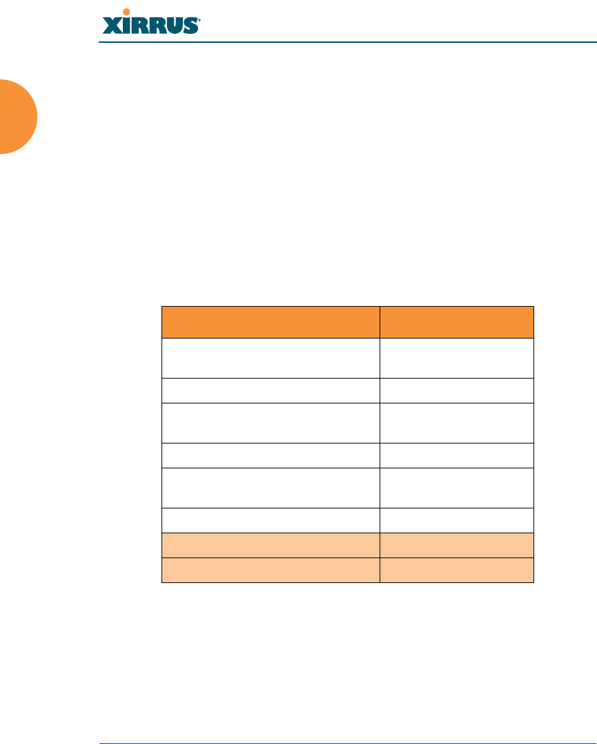
XR500 Series Arrays
These Arrays have one Gigabit Ethernet port and two radios—one multi-state
radio (2.4GHz or 5GHz) and one 5GHz radio. They support 300Mbps, connecting
up to 240 users at one time.
The XR500 provides flexibility for delivering wireless service in low-to-medium
user density scenarios, in challenging deployments in areas with high RF
attenuation, and in isolated or physically separated locations.
Like other XR Arrays, these models have an integrated controller, firewall, threat
sensor and spectrum analyzer. Unlike other XR Arrays, these models have omni-
directional antennas rather than directional antennas.
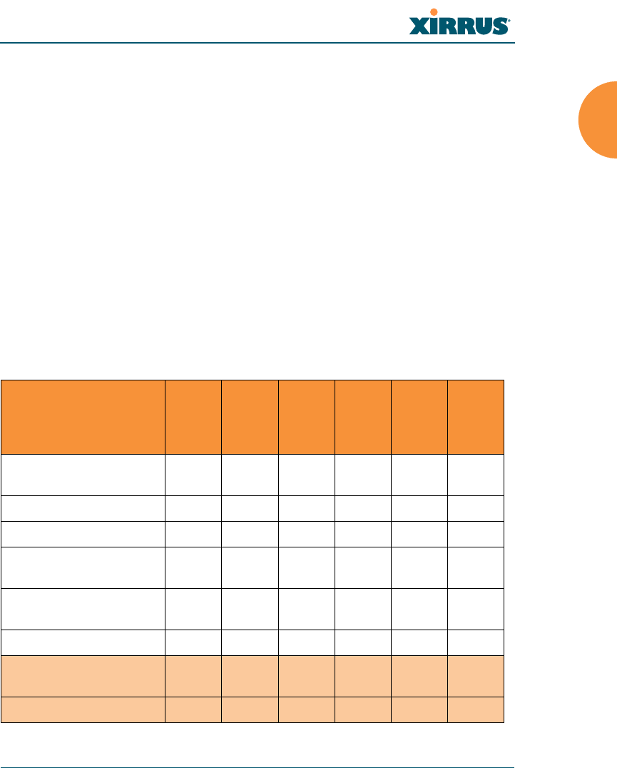
XR-1000 and XR-2000 Series Arrays
These Arrays include models with one Gigabit Ethernet port and two or four
multi-state radios (2.4GHz or 5GHz) that can support 300Mbps or 450Mbps,
connecting upwards of 320 users at one time.
The Xirrus XR-1000 Series Wireless Array is a two slot chassis available in a two
multi-state (2.4GHz or 5GHz) radio configuration supporting up to 160 users with
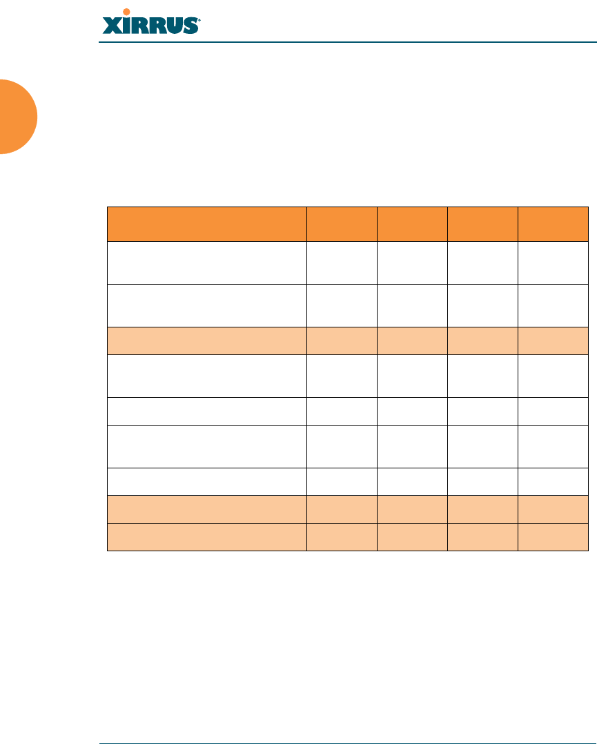
Feature XR520
No. radios: 802.11
a/b/g/n/monitor 2
Radio type 2x2
# Integrated omni-directional
antennas 4
Integrated wireless switch ports 2
Integrated RF spectrum analyzer,
threat sensors Yes
1 Gigabit Uplink Ports 1
Wireless bandwidth 300 Mbps
Users supported 240
Wireless Array
Introduction 7
up to 900Mbps of bandwidth (up to 450 Mbps per radio). The XR-1000 provides
flexibility for delivering wireless service in low user density scenarios,
challenging deployments in areas with high RF attenuation, and in isolated or
physically separated locations. The elliptical-shaped coverage pattern produced
by its directional antennas is ideal for covering facilities with central hallways and
adjacent rooms commonly found in office buildings, hotels, and dormitories.
The Xirrus XR-2000 Series Wireless Array is a four slot chassis available in a four
multi-state (2.4GHz or 5GHz) radio configuration supporting up to 320 users with
up to 1.8Gbps of bandwidth. These models support a range of low to high-
performance applications, including offices, hospitals, campuses and classrooms,
and hotels.
Like all XR Arrays except the XR500 Series, these models integrate multi-state
radios with high gain directional antennas, an onboard multi-gigabit switch,
controller, firewall, threat sensor and spectrum analyzer all built on a modular
chassis designed for future extensibility.
Feature
XR-1220
XR-1230
XR-2220
XR-2230
XR-2420
XR-2430
No. radios: 802.11
a/b/g/n/monitor 222244
Radio type 2x2 3x3 2x2 3x3 2x2 3x3
# Integrated antennas4646812
Integrated wireless
switch ports 224444
Integrated RF spectrum
analyzer, threat sensors Yes Yes Yes Yes Yes Yes
1 Gigabit Uplink Ports 111111
Wireless bandwidth 600
Mbps 900
Mbps 600
Mbps 900
Mbps 1.2
Gbps 1.8
Gbps
Users supported 480 480 480 480 960 960
Wireless Array
8 Introduction
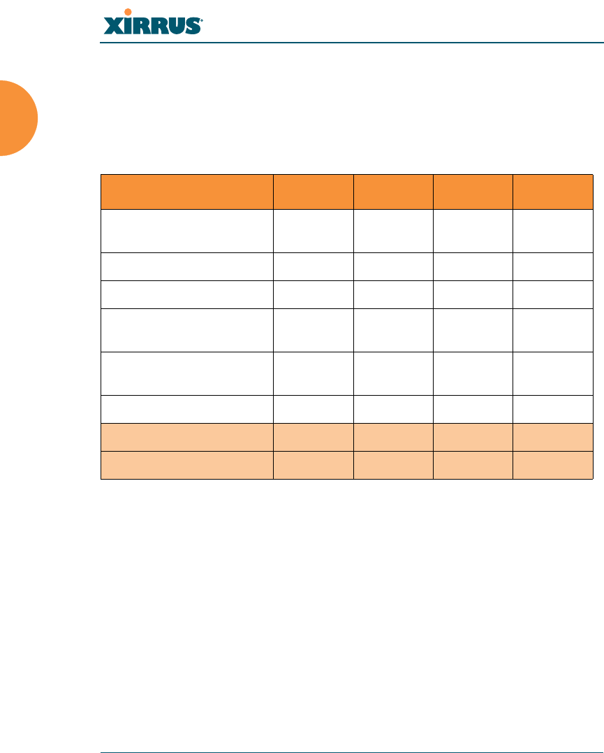
XR-4000 Series Arrays
These Arrays include models with two Gigabit Ethernet ports and four or eight
radios (IAPs), connecting up to 640 users at one time and offering a maximum
wireless bandwidth of 3.6 Gbps (up to 450 Mbps per radio). Smaller models may
be upgraded to eight radios later when your needs change.
Feature XR-4420 XR-4430 XR-4820 XR-4830
Number of radios:
802.11a/b/g/n/monitor 4488
Radio type 2x2 3x3 2x2 3x3
# Integrated antennas 8 12 16 24
Integrated wireless
switch ports 8888
Integrated RF spectrum
analyzer, threat sensors Yes Yes Yes Yes
1 Gigabit Uplink Ports 2 2 2 2
Wireless bandwidth 1.2 Gbps 1.8 Gbps 2.4 Gbps 3.6 Gbps
Users supported 960 960 1920 1920
Wireless Array
Introduction 9
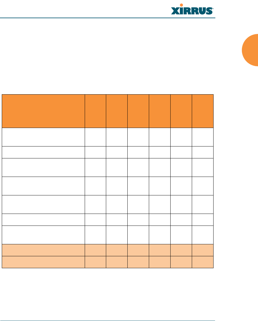
XR-6000 Series Arrays
These Arrays include models with four Gigabit Ethernet ports and up to sixteen
radios, connecting up to 1280 users at one time and offering a maximum wireless
bandwidth of 7.2 Gbps (up to 450 Mbps per radio). Smaller models may be
upgraded to sixteen radios later when your needs change. A 10 Gigabit modular
Ethernet expansion port (DVI connector) is available to meet high traffic
demands. It is used only with an optional Xirrus 10 Gig fiber optics adapter.
See Also
Key Features and Benefits
Wireless Array Product Overview
Power over Gigabit Ethernet (PoGE)
Feature
XR-6820
XR-6830
XR-7220
XR-7230
XR-7620
XR-7630
Number of radios:
802.11a/b/g/n/monitor 8 8 12 12 16 16
Radio type 2x2 3x3 2x2 3x3 2x2 3x3
Number of
integrated antennas 16 24 24 36 32 48
Integrated wireless switch
ports 16 16 16 16 16 16
Integrated RF spectrum
analyzer, threat sensors YesYesYesYesYesYes
1 Gigabit Uplink Ports 444444
External 10 Gigabit Modular
Expansion Port 111111
Wireless bandwidth (Gbps) 2.4 3.6 3.6 5.4 4.8 7.2
Users supported 896 896 1344 1344 1792 1792
Wireless Array
10 Introduction
Why Choose the Xirrus Wireless Array?
XN Wireless Array Product Family
The following tables provide an overview of the main features supported by the
XN Array product family.
XN Family of Arrays
See Also
Key Features and Benefits
Wireless Array Product Overview
Power over Gigabit Ethernet (PoGE)
Why Choose the Xirrus Wireless Array?
Feature XN16 XN12 XN8 XN4
Number of
802.11a/b/g/n radios 4444
Number of
802.11a/n radios 12840
Total r adi os 16 12 8 4
Number of
integrated antennas 48 36 36 20
Integrated Wi-Fi switch ports 16 12 8 4
Integrated RF spectrum
analyzer, threat sensors Yes Yes Yes Yes
Uplink Ports 2221
Wireless bandwidth 4.8 Gbps 3.6 Gbps 2.4 Gbps 1.2 Gbps
Users supported 1280 960 640 320

Wireless Array
Introduction 11
Enterprise Class Security
The latest and most effective wireless encryption security standards, including
WPA (Wireless Protected Access) and WPA2 with 802.11i AES (Advanced
Encryption Standard) are available on the Wireless Array. In addition, the use of
an embedded RADIUS server (or 802.1x with an external RADIUS server) ensures
user authentication — multiple Arrays can authenticate to the optional XMS,
ensuring only authorized Arrays become part of the wireless network. With the
Xirrus Advanced Feature Sets, intrusion detection and prevention, site
monitoring, and RF spectrum analysis are performed in the background by the
Array automatically.
Deployment Flexibility
Xirrus’ unique multi-radio architecture (on all Arrays except the XR500 Series)
generates 360 degrees of sectored high-gain 802.11a/b/g/n coverage that
provides extended range and the highest possible data rates for a large volume of
clients. Each sector can be adjusted automatically or manually, creating a pattern
of wireless coverage perfectly tailored to individual customer needs. For example:
Figure 3. Wireless Coverage Patterns
Figure 3 depicts the following two scenarios:
Full pattern coverage
All radios are activated with coverage spanning 360 degrees. If within
range, clients will always receive coverage regardless of their geographic
outside wall
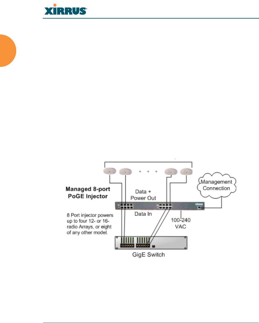
Wireless Array
12 Introduction
position relative to the Array. Radios may be assigned to 2.4 GHz and/or
5.0 GHz bands in any desired pattern.
Partial pattern coverage
If desired, the Wireless Array can be deployed close to an exterior wall. In
this case, half of all available radios have been deactivated to prevent
redundant signals from “bleeding” beyond the site’s perimeter wall. This
configuration may also be used in those cases where you want to restrict
wireless coverage to selected areas of the building’s interior.
Power over Gigabit Ethernet (PoGE)
The Xirrus-supplied XP1, XP2, and XP8 Power over Gigabit Ethernet modules
provide power to your Arrays over the same Cat 5e or Cat 6 cable used for data,
eliminating the need to run power cables and provide an AC power outlet in
proximity to each unit. Managed modules provide the ability to control power
using XMS.
Figure 4. XP8 - Power over Ethernet Usage
Specific models of the Array are compatible with specific PoGE modules.
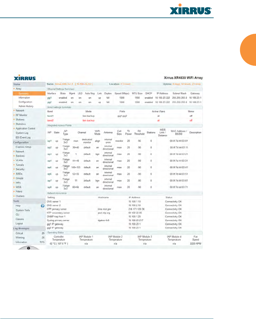
Wireless Array
Introduction 13
Enterprise Class Management
The Wireless Array can be configured with its default RF settings, or the RF
settings can be customized using the Array’s embedded Web Management
Interface (WMI). The WMI enables easy configuration and control from a
graphical console, plus a full complement of troubleshooting tools and statistics.
Figure 5. WMI: Array Status
In addition, a fully featured Command Line Interface (CLI) offers IT professionals
a familiar management and control environment. SNMP (Simple Network
Management Protocol) is also supported to allow management from an SNMP
compliant management tool, such as the optional Xirrus Management System.
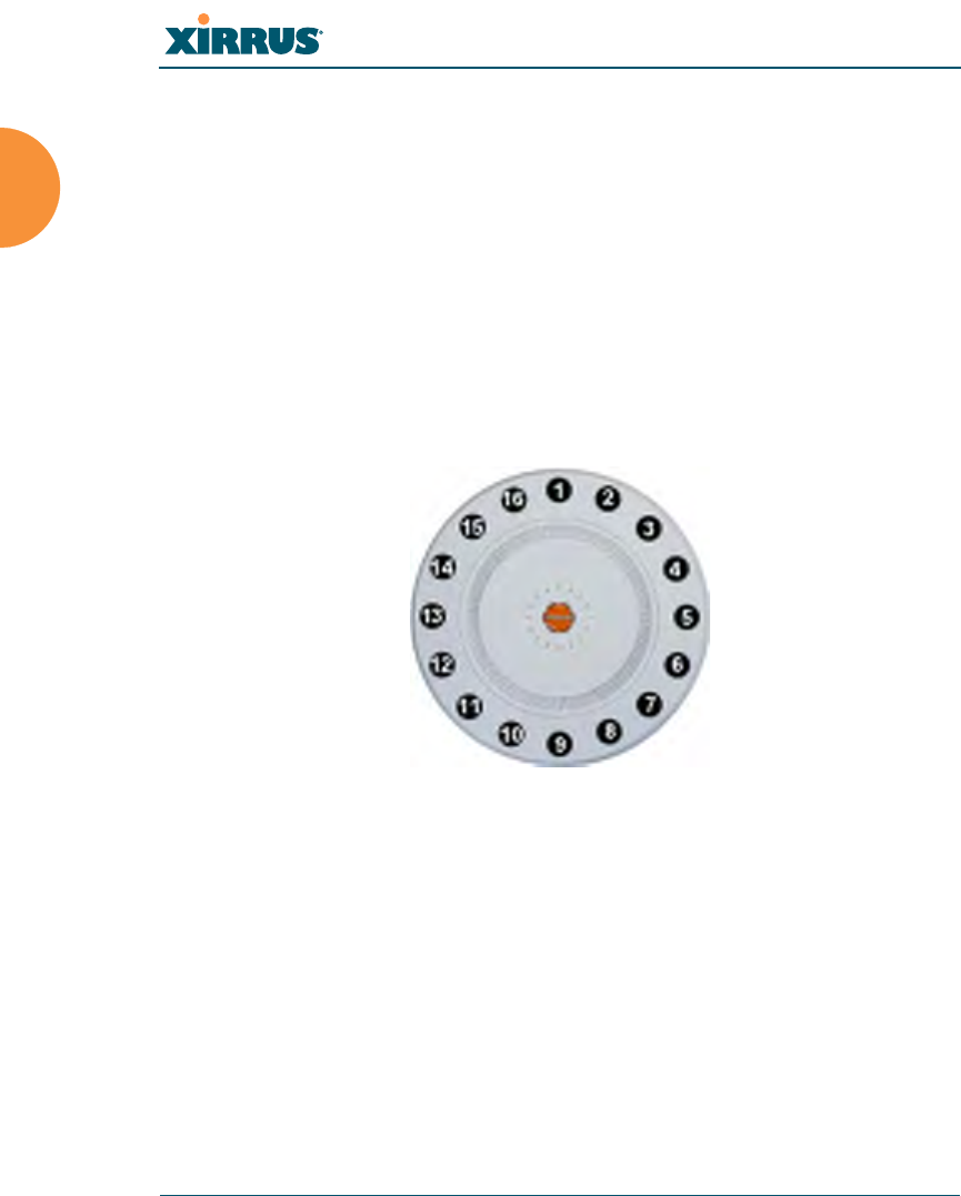
Wireless Array
14 Introduction
Key Features and Benefits
This section describes some of the key product features and the benefits you can
expect when deploying the Wireless Array (the XR-7630 product is used as an
example in this section).
High Capacity and High Performance
Figure 6. Layout of IAPs (XR-7630)
The XR-7630 version of the Wireless Array (Figure 6) enables wireless
connectivity and easily handles time-sensitive traffic such as voice. This model
includes four Gigabit uplink ports for connection to the wired network. Its sixteen
IAPs (radios) provide a maximum wireless capacity of 7.2 Gbps, which offers
ample reserves for the high demands of current and future applications. Of the
sixteen IAPs, fifteen operate as radios which may be set up to serve your choice of
client types — any or all of 802.11a/b/g/n (5 GHz or 2.4 GHz bands), providing
backwards compatibility with 802.11b and 802.11g.
In the recommended configuration, one IAP is configured in RF monitoring and
intrusion detection/prevention mode.
For deployments of more than five Arrays, we recommend that you use the
Xirrus Management System (XMS). The XMS offers a rich set of features
for fine control over large deployments.

Wireless Array
Introduction 15
Extended Coverage
One XR-7630 solution enables you to replace fifteen access points (including one
omnidirectional IAP for monitoring the network). Fifteen IAP radios with
integrated directional antennas provide increased wireless range and enhanced
data rates in all directions. With a Wireless Array deployed, far fewer access
points are needed and wired-like resiliency is delivered throughout your wireless
network. Your Wireless Array deployment ensures:
Continuous connectivity if an IAP (radio) fails.
Continuous connectivity if an Array fails.
Continuous connectivity if a WDS link or switch fails.
Continuous connectivity if a Gigabit uplink or switch fails.
Non-Overlapping Channels
Complete use of non-overlapping channels limits interference and delivers
maximum capacity. On the XR-7630, up to 16 non-overlapping channels are fully
utilized across the 5GHz and 2.4GHz spectrums (up to 12 across the 5GHz
spectrum plus up to 3 across the 2.4 GHz spectrum — typically, one additional
radio is used as a dedicated RF monitor).
SDMA Optimization
SDMA (Spatial Division Multiple Access) technology provides full 360° coverage
while allowing independent channel and power output customization. Also
supports fast inter-zone handoffs for time-sensitive applications and roaming.
Fast Roaming
Utilizes the Xirrus Roaming Protocol (XRP) ensuring fast and seamless roaming
capabilities between IAPs or Arrays at both Layer 2 and Layer 3.
Easy Deployment
The Xirrus Management System (XMS) offers real time monitoring and
management capabilities for the wireless network — ideal for the Enterprise
market. It also allows you to import floor plans to help you plan your
deployment. The Xirrus Wireless Array chassis has a plenum rated, lockable and
tamper resistant case.

Wireless Array
16 Introduction
Secure Wireless Access
Multiple layers of authentication and encryption ensure secure data
transmissions. The Wireless Array is 802.11i compliant with line-rate encryption
support for 40 and 128 bit WEP, WPA and WPA2 with TKIP and AES encryption.
Authentication is provided via 802.1x, including PEAP, EAP-TLS, EAP-TTLS,
EAP-SIM, EAP-GRC, and LEAP (Lightweight Extensible Authentication Protocol)
passthrough. Intrusion detection and prevention provide proactive monitoring of
the environment for threats.
Applications Enablement
The Wireless Array’s QoS (Quality of Service) functionality combined with true
switch capabilities enable high density video and Voice over Wireless LAN
deployments. Compliant with 802.1p and 802.1Q standards.
See Also
Wireless Array Product Overview
Power over Gigabit Ethernet (PoGE)
Why Choose the Xirrus Wireless Array?
Advanced Feature Sets
The Wireless Array offers a family of powerful functionality packages, including
the RF Performance Manager (RPM), RF Security Manager (RSM), and RF
Analysis Manager (RAM). These packages are separately licensed for operation
on your Array.
Xirrus Advanced RF Performance Manager (RPM)
The Xirrus RPM optimizes the bandwidth usage and station performance of
802.11n wireless networks. Leveraging the multiple integrated access point
(multi-radio) design of the Xirrus Wireless Array, RPM manages the allocation of
wireless bandwidth to wireless stations across multiple RF channels. The result
maximizes overall network performance with superior flexibility and capacity.
Today's wireless infrastructure is faced with ever increasing numbers and
variations of wireless enabled clients, whether in the form of notebooks, netbooks,
smart phones, IP phones, printers, projectors, cameras, RFID tags, etc. The advent

Wireless Array
Introduction 17
of higher speed 802.11n wireless and its increased use of the 5GHz spectrum adds
to the number of variables today's wireless networks must accommodate.
Backwards compatibility with older clients is crucial, however their operation in a
wireless network can significantly hinder the performance of faster clients. As an
example, 802.11b wireless stations communicate more than 10 times slower than
802.11n stations.
With each of the Array’s multiple radios operating on a different channel, RPM
selects the ideal radio for each station. High-speed stations are grouped together
on radios with other high speed stations, while lower speed stations are combined
with other lower speed stations. This ensures optimal performance for high-speed
802.11n stations without compromise.
The complete feature set of the RPM package includes:
WDS (Wireless Distribution System) for point-to-point communication
Wireless Mode per IAP
Sharp Cell technology
Wireless Data Rate Optimization
Wireless Traffic Shaping
Wireless Voice Call Admission Control
Fast Layer 2 and 3 Roaming
Standby Mode
Xirrus Advanced RF Security Manager (RSM)
The Xirrus RSM improves security and minimizes the risk in deploying 802.11n
wireless networks. Leveraging an integrated 24/7 threat sensor and hardware-
based encryption/decryption in each Array, RSM secures the wireless network
from multiple types of threats. The result delivers uncompromised overall
network security with superior flexibility and performance.
Today's wireless networks face a number of potential security threats in the form
of rogue access points, ad-hoc clients, unauthorized clients, wireless-based
attacks, eavesdropping, etc. As 802.11n is increasingly adopted in enterprise
networks, defending against these threats becomes more critical. With the Array’s

Wireless Array
18 Introduction
dedicated threat sensor radio scanning all channels in the 2.4GHz and 5GHz
spectrums, RSM searches for security threats and automatically mitigates them.
High performance encryption/decryption in the enterprise wireless network is a
must. The wireless network needs to support each client using the highest level of
encryption (WPA2 Enterprise/128 bit AES) and without degrading the overall
performance of the network. Xirrus incorporates hardware-based encryption/
decryption into each Array, delivering line-rate encryption at the edge of the
network instead of at a choke point within a centralized controller.
The complete feature set of the RSM package includes:
Wireless IDS/IPS (Intrusion Detection/Prevention System)
Wireless stateful firewall
User group policies
Authenticated guest access gateway
NAC integration
Xirrus Advanced RF Analysis Manager (RAM)
The RF Advanced Analysis Manager (RAM) tests and troubleshoots 802.11n
wireless networks. The deployment of 802.11n presents a set of unique challenges
based on technology differences with legacy 802.11a/b/g networks, both on the
wireless infrastructure and client side. Xirrus' RAM equips each Wireless Array
with a powerful set of tools and features to optimally tune and verify an 802.11n
installation, as well as give IT administrators the ability to troubleshoot issues
that may occur within the wireless environment.
The 802.11n standard will continue to evolve over the next several years with
additional performance and optional functions, along with ongoing stream of
IEEE 802.11 amendments. This changing wireless landscape mandates that
appropriate tools are available to the user to analyze, optimize, and troubleshoot
their changing environments.
The distributed architecture of the Array enables the execution of powerful
wireless and networking analysis at the edge of the network where packets
traverse the wireless-to-wired boundary. The Array includes an embedded

Wireless Array
Introduction 19
wireless controller with the necessary computing and memory resources to
provide these functions securely at the network's edge.
The key elements of the RAM package include:
RF Analysis – An embedded Spectrum Analyzer leverages the dedicated
threat sensor radio in each Wireless Array to provide a continual view of
utilization, interference, and errors across all available wireless channels.
Packet Analysis – Integrated packet capture provides filterable views of
all traffic traversing on the wired and wireless interfaces of the Array.
Performance Analysis – Embedded traffic generation enables the
throughput of the Array’s wireless or wired interfaces to be analyzed.
Failure Recovery – Radio Assurance provides an automatic self-test and
self healing mechanism that ensures continuous system operation.
Netflow Support
Network Tools: ping, RADIUS ping, traceroute
About this User’s Guide
This User’s Guide provides detailed information and procedures that will enable
wireless network administrators to install, configure and manage the Wireless
Array so that end users can take full advantage of the product’s features and
functionality without technical assistance.
Organization
Topics and procedures are organized by function under the following chapter
headings:
Introduction
Provides a brief introduction to wireless technology, an overview of the
product, including its key features and benefits, and presents the product
specifications.
Installing the Wireless Array
Defines prerequisites for deploying and installing the Array and provides
instructions to help you plan and complete a successful installation.

Wireless Array
20 Introduction
The Web Management Interface
Offers an overview of the product’s embedded Web Management
Interface, including its content and structure. It emphasizes what you
need to do to ensure that any configuration changes you make are
applied, and provides a list of restricted characters. It also includes
instructions for logging in to the Array with your Web browser.
Viewing Status on the Wireless Array
Describes the status and statistics displays available on the Array using
its embedded Web Management Interface.
Configuring the Wireless Array
Contains procedures for configuring the Array using its embedded Web
Management Interface.
Using Tools on the Wireless Array
Contains procedures for using utility tools provided in the Web
Management Interface. It includes procedures for upgrading the system
firmware, uploading and downloading configurations and other files,
using diagnostic tools, and resetting the Array to its factory defaults.
The Command Line Interface
Includes the commands and the command structure used by the Wireless
Array’s Command Line Interface (CLI), and provides a procedure for
establishing a Telnet connection to the Array. This chapter also includes
some sample key configuration tasks using the CLI.
Appendix A: Quick Reference Guide
Contains the product’s factory default settings.
Appendix B: Technical Support
Offers guidance to resolve technical issues, including general hints and
tips to enhance your product experience, and a procedure for isolating
problems within an Array-enabled wireless network. Also includes
Frequently Asked Questions (FAQs) and Xirrus contact information.

Wireless Array
Introduction 21
Appendix C: Notices
Contains the legal notices, licensing, and compliance statements for the
Array. Please read this section carefully.
Glossary of Terms
Provides an explanation of terms directly related to Xirrus product
technology, organized alphabetically.
Index
The index is a valuable information search tool. Use the index to locate
specific topics discussed in this User’s Guide. Simply click on any page
number in the index to jump to the referenced topic.
Notes and Cautions
The following symbols are used throughout this User’s Guide:
Screen Images
Some screen images of the Web Management Interface have been modified for
clarity. For example, an image may have been cropped to highlight a specific area
of the screen, and/or sample data may be included in some fields.
This symbol is used for general notes that provide useful supplemental
information.
!This symbol is used for cautions. Cautions provide critical information that
may adversely affect the performance of the product.


Wireless Array
Installing the Wireless Array 23
Installing the Wireless Array
The instructions for completing a successful installation include the following
topics:
“Installation Prerequisites” on page 23.
“Planning Your Installation” on page 26.
“Installation Workflow” on page 57.
“Installing Your Wireless Array” on page 59.
“Powering Up the Wireless Array” on page 63.
“Establishing Communication with the Array” on page 66.
“Performing the Express Setup Procedure” on page 71.
Installation Prerequisites
Your Wireless Array deployment requires the presence of hardware and services
in the host wired/wireless network, including:
Power Source
Most Arrays are powered via Xirrus-supplied Power over Gigabit
Ethernet. PoGE supplies power over the same Cat 5e or Cat 6 cable used
for data, thus reducing cabling and installation effort. PoGE power
injector modules are available in 1-, 2-, and 8-port configurations and are
typically placed near your Gigabit Ethernet switch. An AC outlet is
required for each injector module. Current Array models have integrated
splitters, so no separate splitter is required.
Ethernet ports
You need at least one 100/1000 BaseT port to establish wired Gigabit
Ethernet connectivity. XR Series Arrays have one, two, or four Gigabit
ports, depending on the model (see “XR Wireless Array Product Family”
on page 6). XN Series Arrays have one or two Gigabit ports, depending
on the model. Some models also have one 10/100 BaseT port which may
be used for product management if desired. See “XN Wireless Array
Product Family” on page 10.

Wireless Array
24 Installing the Wireless Array
Secure Shell (SSH) utility
To establish secure remote command line access to the Array, you need a
Secure Shell (SSH) utility, such as PuTTY. The utility must be configured
to use SSH-2, since the Array will only allow SSH-2 connections.
Secure Web browser
Either Internet Explorer (version 7.0 or higher), Mozilla Firefox (version
3.0 or higher), Chrome (version 3.0 or higher), or Safari (version 5.0 or
higher). A secure Web browser is required for Web-based management of
the Array. The browser must be on the same subnet as the Array, or you
must set a static route for management as described in the warning
above.
Serial connection capability
To connect directly to the console port on the Array (all models except
XR500 and XR-1000 Series), your computer must be equipped with a male
9-pin serial port and terminal emulation software (for example,
HyperTerminal). The Xirrus Array only supports serial cable lengths up
to 25’ per the RS-232 specification.
Use the following settings when establishing a serial connection:
!The Array’s Ethernet ports should be connected to an Ethernet switch, not
an Ethernet hub — if a hub is used, we recommend that you do not bond-
pair Ethernet ports.
Bits per second 115,200
Data bits 8
Parity None
Stop bits 1
Flow control None

Wireless Array
Installing the Wireless Array 25
Optional Network Components
The following network components are optional.
Xirrus Management System (XMS)
The optional XMS offers powerful management features for small or large
Wireless Array deployments.
External RADIUS server
Although your Array comes with an embedded RADIUS server, for
802.1x authentication in large deployments you may want to add an
external RADIUS server.
Client Requirements
The Wireless Array should only be used with Wi-Fi certified client
devices.
See Also
Coverage and Capacity Planning
Failover Planning
Planning Your Installation

Wireless Array
26 Installing the Wireless Array
Planning Your Installation
This section provides guidelines and examples to help you plan your Xirrus
Wireless Array deployment to achieve the best overall coverage and performance.
We recommend you conduct a site survey to determine the best location and
settings for each Array you install.
The following topics are discussed:
“General Deployment Considerations” on page 26
“Coverage and Capacity Planning” on page 28
“IEEE 802.11n Deployment Considerations” on page 35
“Failover Planning” on page 42
“Power Planning” on page 45
“Security Planning” on page 46
“Port Requirements” on page 48
“Network Management Planning” on page 52
“WDS Planning” on page 53
“Common Deployment Options” on page 56
General Deployment Considerations
The Wireless Array’s unique multi-radio architecture generates 360 degrees of
sectored high-gain 802.11a/b/g/n or 802.11a/b/g coverage that provides
extended range. (Note that XR500 Series radios are omni-directional rather than
sectored.) However, the number, thickness and location of walls, ceilings or other
objects that the wireless signals must pass through may affect the range. Typical
ranges vary depending on the types of materials and background RF (radio
For a complete discussion of implementing Voice over Wi-Fi on the Array,
see the Xirrus Voice over Wireless Application Note in the Xirrus
Resource Center.
For optimal placement of Arrays, we recommend that a site survey be
performed by a qualified Xirrus partner.
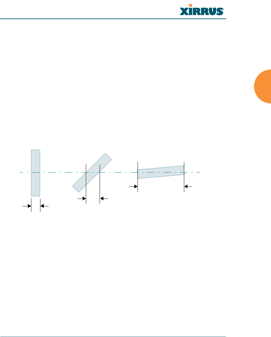
Wireless Array
Installing the Wireless Array 27
frequency) noise at your location. To maximize wireless range, follow these basic
guidelines:
1. Keep the number of walls and ceilings between the Array and your
receiving devices to a minimum — each wall or ceiling can reduce the
wireless range from between 3 and 90 feet (1 to 30 meters). Position your
devices so that the number of walls or ceilings is minimized.
2. Be aware of the direct line between each device. For example, a wall that
is 1.5 feet thick (half a meter) at 90° is actually almost 3 feet thick (or 1
meter) when viewed at a 45° angle. At an acute 2° degree angle the same
wall is over 42 feet (or 14 meters) thick! For best reception, try to ensure
that your wireless devices are positioned so that signals will travel
straight through a wall or ceiling.
Figure 7. Wall Thickness Considerations
3. Try to position wireless client devices so that the signal passes through
drywall (between studs) or open doorways and not other materials that
can adversely affect the wireless signal.
See Also
Coverage and Capacity Planning
Common Deployment Options
Installation Prerequisites
90° 45°
1.5 feet/
.5 m ~ 3 feet/
1 m
> 42 feet\
14 m
2°
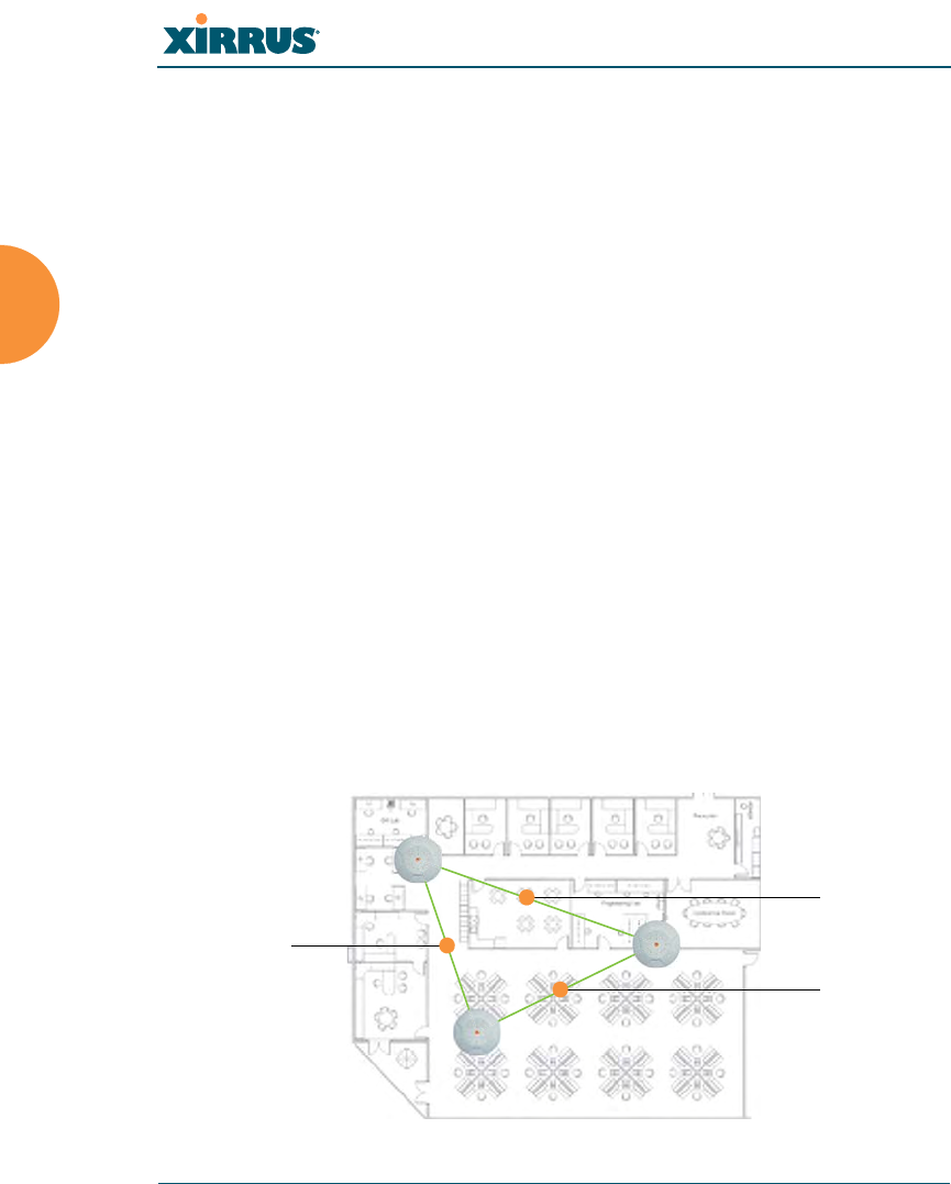
Wireless Array
28 Installing the Wireless Array
Coverage and Capacity Planning
This section considers coverage and capacity for your deployment(s), including
placement options, RF patterns and cell sizes, area calculations, roaming
considerations, and channel allocations.
Placement
Use the following guidelines when considering placement options:
1. The best placement option for the Array is ceiling-mounted within an
open plan environment (cubicles rather than fixed walls).
2. Keep the Array away from electrical devices or appliances that generate
RF noise. Because the Array is generally mounted on ceilings, be aware of
its position relative to lighting (especially fluorescent lighting) — we
recommend maintaining a distance of at least 3 to 6 feet (1 to 2 meters).
Figure 8. Unit Placement
Note that several advanced features in this section are part of the Xirrus
Advanced RF Performance Manager (RPM). They require the license
installed on the Array to include support for RPM. Please see “About
Licensing and Upgrades” on page 361.
XR500 Series radios are omni-directional rather than directional (sectored),
and discussions involving sectored radios are not applicable to these Arrays.
100 ft/ 30m
100 ft/ 30 m
100 ft/
30 m

Wireless Array
Installing the Wireless Array 29
3. If using multiple Arrays in the same area, maintain a distance of at least
100ft/30m between Arrays if there is direct line-of-sight between units, or
at least 50ft/15m if a wall or other barrier exists between units.
RF Patterns
The Wireless Array allows you to control — automatically or manually — the
pattern of wireless coverage that best suits your deployment needs. You can
choose to operate with full coverage, half coverage, or custom coverage (by
enabling or disabling individual sectors).
Full (Normal) Coverage
In normal operation, the Array provides a full 360 degrees of coverage.
Figure 9. Full (Normal) Coverage
Half Coverage
Figure 10. Adjusting RF Patterns
If installing a unit close to an exterior wall, you can deactivate half of the radios to
prevent redundant signals from “bleeding” beyond the wall and extending
outside wall
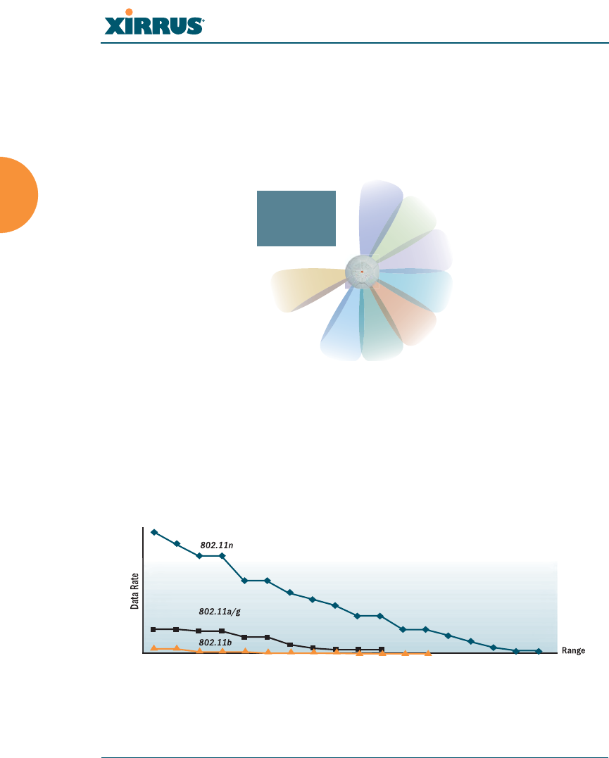
Wireless Array
30 Installing the Wireless Array
service into public areas. The same principle applies if you want to restrict service
to an adjacent room within the site.
Custom Coverage
Where there are highly reflective objects in proximity to the Array, you can turn
off specific radios to avoid interference and feedback.
Figure 11. Custom Coverage
Capacity and Cell Sizes
Cell sizes should be estimated based on the number of users, the applications
being used (for example, data/video/voice), and the number of Arrays available
at the location. The capacity of a cell is defined as the minimum data rate desired
for each sector multiplied by the total number of sectors being used.
Figure 12. Connection Rate vs. Distance
Figure 12 shows relative connection rates for 802.11n vs. 802.11a/g and 802.11b,
and the effect of distance on the connection rates. Wireless environments can vary
object
reflective

Wireless Array
Installing the Wireless Array 31
greatly so the actual rates may be different depending on the specific network
deployment.
Fine Tuning Cell Sizes
Adjusting the transmit power allows you to fine tune cell sizes. There are four
standard sizes — Small, Medium, Large, or Max (the default is Max). There is also
an Auto setting that automatically determines the best cell size, and a Manual
setting that allows you to choose your power settings directly.
Figure 13. Transmit Power
Auto Cell Size is an automatic, self-tuning mechanism that balances cell size
between Arrays to guarantee coverage while limiting the RF energy that could
extend beyond the organizational boundary. Auto Cell uses communication
between Arrays to dynamically set radio power so that complete coverage is
provided to all areas, yet at the minimum power level required. This helps to
minimize potential interference with neighboring networks. Additionally, Arrays
running Auto Cell automatically detect and compensate for coverage gaps caused
by system interruptions. To enable the Auto Cell Size feature, go to “RF Power &
Sensitivity” on page 316. For a complete discussion of the Auto Cell size feature,
see the Xirrus Auto Cell Application Note in the Xirrus Resource Center.
The XN4 has a smaller range than the larger Arrays.
Large
Medium
Small

Wireless Array
32 Installing the Wireless Array
If you are installing many units in proximity to each other, we recommend that
you use Auto Cell Size; otherwise, reduce the transmit power using manual
settings to avoid excessive interference with other Arrays or installed APs. See
also, “Coverage and Capacity Planning” on page 28.
Sharp Cell
This patented Xirrus RF management option automatically creates more
intelligently defined cells and improves performance by creating smaller, high-
throughput cells. By dynamically limiting each cell to a defined boundary (cell
size), the trailing edge bleed of RF energy is reduced, thus minimizing
interference between neighboring Wireless Arrays or other Access Points. To
enable the Sharp Cell feature, go to “RF Power & Sensitivity” on page 316. For
more information about this feature, see the Xirrus Sharp Cell Application Note in
the Xirrus Resource Center.
Roaming Considerations
Cells should overlap approximately 10 - 15% to accommodate client roaming.
Figure 14. Overlapping Cells
XR500 Series radios are omni-directional rather than directional (sectored),.
This feature is not applicable to these Arrays.
ROAMING
10 - 15% overlap

Wireless Array
Installing the Wireless Array 33
Allocating Channels
Because the Wireless Array is a multi-channel device, allocating the best channels
to radios is important if peak performance is to be maintained.
Automatic Channel Selection
We recommend that you allow the Array to make intelligent channel allocation
decisions automatically. In the automatic mode, channels are allocated
dynamically, driven by changes in the environment. Auto Channel assignment is
performed by scanning the surrounding area for RF activity on all channels, then
automatically selecting and setting channels on the Array to the best channels
available. This function is typically executed when initially installing Arrays in a
new location and may optionally be configured to execute periodically to account
for changes in the RF environment over time. Auto Channel selection has
significant advantages, including:
Allows the Array to come up for the first time and not interfere with
existing equipment that may be already running, thereby limiting co-
channel interference.
More accurately tunes the RF characteristics of a wireless installation than
manual configuration since the radios themselves are scanning the
environment from their physical location.
May be configured to run periodically.
To set up the automatic channel selection feature, go to “Advanced RF Settings”
on page 313.

Wireless Array
34 Installing the Wireless Array
Manual Channel Selection
You can manually assign channels on a per radio basis, though manual selection
is not recommended (and not necessary).
Figure 15. Allocating Channels Manually
See Also
Failover Planning
Installation Prerequisites
To avoid co-channel interference, do not select adjacent channels for radios
that are physically next to each other.
Maintain channel separation

Wireless Array
Installing the Wireless Array 35
IEEE 802.11n Deployment Considerations
The Xirrus Arrays support IEEE 802.11n on all IAPs, in both 2.4 GHz and 5 GHz
bands. Use of 802.11n offers significant benefits:
Higher data rates
Higher throughput
Supports more users
More robust connections
Increased coverage area
More secure connections — supports WPA2 (Wi-Fi Protected Access 2)
These benefits result in better support for a wide range of applications such as
voice and video, intensive usage such as CAD/CAM and backups, dense user
environments, and for manufacturing and warehousing environments.
The techniques that 802.11n uses to realize these performance improvements, and
the results that can be expected are discussed in:
“MIMO (Multiple-In Multiple-Out)” on page 36
“Multiple Data Streams — Spatial Multiplexing” on page 38
“Channel Bonding” on page 39
“Improved MAC Throughput” on page 40
“Short Guard Interval” on page 40
“Obtaining Higher Data Rates” on page 41
“802.11n Capacity” on page 42
Two very important techniques to consider are Channel Bonding and Multiple
Data Streams — Spatial Multiplexing because they contribute a large portion of
Note that the license installed on the Array must include support for
802.11n. Please see “About Licensing and Upgrades” on page 361.
While 802.11n increases coverage area by almost doubling the reach, you
must consider the legacy wireless devices in your network. Wireless stations
connecting using 802.11a/b/g will still be subject to a reach of up to 100 feet,
depending on the environment.
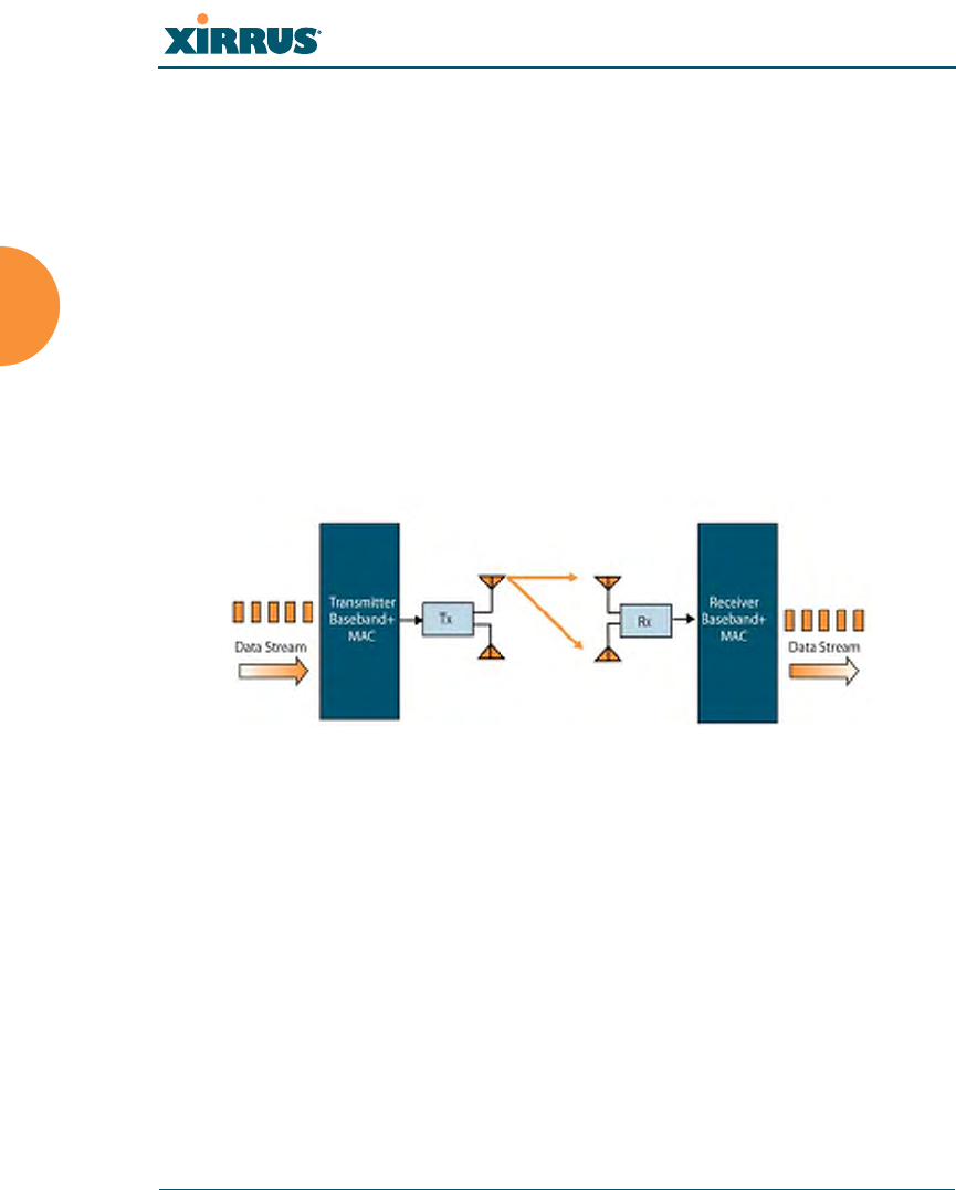
Wireless Array
36 Installing the Wireless Array
802.11n’s speed improvements and because they are optional and configurable, as
opposed to the parts of 802.11n that are fixed. While the settings for 802.11n IAPs
come pre-configured on the Array for robust performance in typical usage, you
should review the settings for your deployment, especially channel bonding. A
global setting is provided to enable or disable 802.11n mode. See “Global Settings
.11n” on page 304 to configure 802.11n operation.
MIMO (Multiple-In Multiple-Out)
MIMO (Multiple-In Multiple-Out) signal processing is one of the core
technologies of 802.11n. It mitigates interference and maintains broadband
performance even with weak signals.
Prior to 802.11n, a data stream was transmitted via one antenna. At the receiving
end, the antenna with the best signal was selected to receive data. (Figure 16)
Figure 16. Classic 802.11 Signal Transmission
MIMO signal processing uses multiple antennas to send and receive data. It takes
advantage of multipath reflections to improve signal coherence and greatly
increase receiver sensitivity (Figure 17).
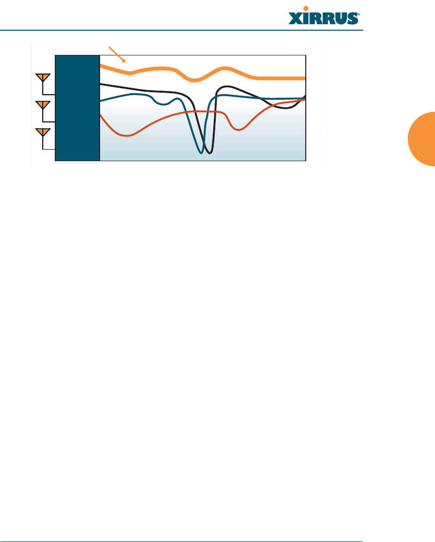
Wireless Array
Installing the Wireless Array 37
Figure 17. MIMO Signal Processing
Multipath signals were considered to be interference by 802.11a/b/g radios, and
degraded performance. In 802.11n, these signals are used to enhance
performance. This extra sensitivity can be used for greater range or higher data
rates. The enhanced signal is the processed sum of individual antennas. Signal
processing eliminates nulls and fading that any one antenna would see. MIMO
signal processing is sophisticated enough to discern multiple spatial streams (see
Multiple Data Streams — Spatial Multiplexing). There are no settings to configure
for MIMO.
Frequency Across Subcarriers
Attenuation
Antenna 1 Signal
MIMO Processed Signal
Antenna 2 Signal
Antenna 3 Signal
Receiver
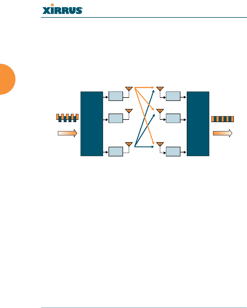
Wireless Array
38 Installing the Wireless Array
Multiple Data Streams — Spatial Multiplexing
Spatial Multiplexing transmits completely separate data streams on different
antennas (in the same channel) that are recombined to produce new 802.11n data
rates. Higher data rates are achieved by splitting the original data stream into
separate data streams. Each separate stream is transmitted on a different antenna
(using its own RF chain). MIMO signal processing at the receiver can detect and
recover each stream. Streams are then recombined, yielding higher data rates.
Figure 18. Spatial Multiplexing
Spatial multiplexing can double, triple, or quadruple the date rate, depending on
the number of transmit antennas used. You can configure the number of chains
(i.e., streams) separately for transmitting and receiving. By default, the Array uses
three chains for transmitting and receiving (see “Global Settings .11n” on
page 304).
M
Rx 1
Rx 2
Rx
M
M
Transmitter
Data Stream Data Stream
Receiver
Tx 1
Tx 2
Tx
N
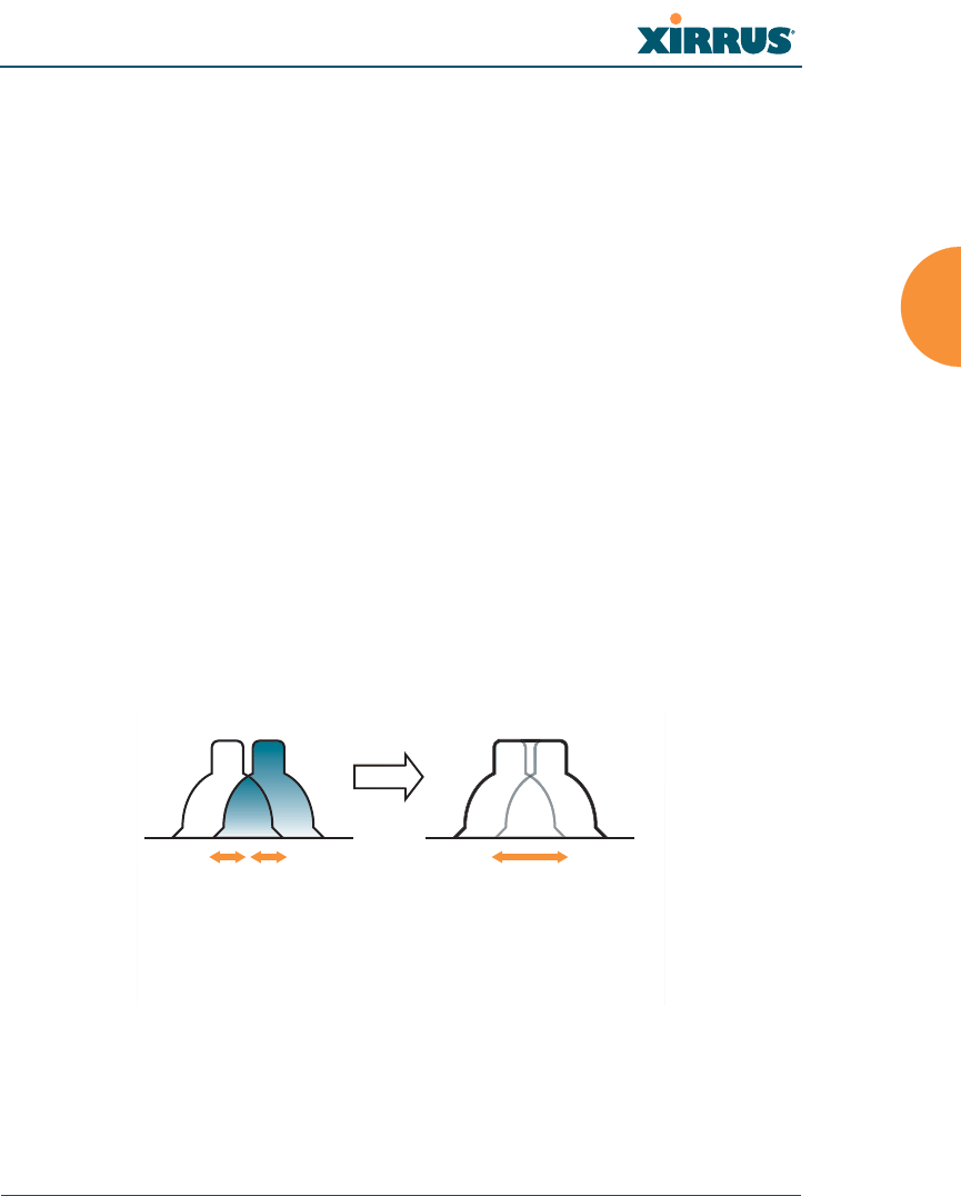
Wireless Array
Installing the Wireless Array 39
Channel Bonding
Channel bonding increases data rates by combining two adjacent 20 MHz
channels into one 40 MHz channel. This increases the data rate to slightly more
than double.
A bonded 40 MHz channel is specified in terms of the Primary channel and the
adjacent channel to Bond. The Bond channel is represented by +1 to use the
channel above the Primary channel, or -1 to use the channel below. In the example
shown, Channel 40 is the Primary channel and it is bonded to Channel 36, the
channel below it, by specifying -1. Be aware that Channel Bonding can make
channel planning more difficult, since you are using two channels for an IAP. We
recommend the use of the 5 GHz band, since it has many more channels than the
2.4 GHz band, and thus more channels are available for bonding.
The Array provides an Automatic Channel Bonding setting that will
automatically select the best channel for bonding on each IAP. If you enable this
option, you may select whether bonding will be dynamic (the bonded channel
changes in response to environmental conditions) or static (the bonded channel
will not be changed. See “Global Settings .11n” on page 304. To configure channel
bonding manually, on a per-IAP basis, see “IAP Settings” on page 274.
Figure 19. Channel Bonding
Ch# Ch#
40
20 MHz 20 MHz
36
40 MHz
(40, -1)
Standard 802.11 channels are
effectively 20MHz wide.
Channel bonding combines
two adjacent 20MHz channels
into a single 40MHz channel
providing increased throughput.
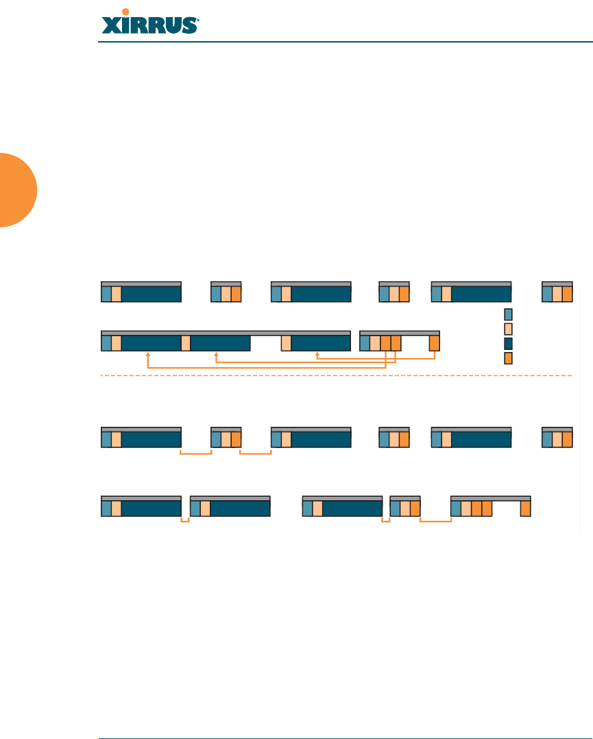
Wireless Array
40 Installing the Wireless Array
Improved MAC Throughput
These changes make 802.11n transmission of MAC frames 40% more efficient than
legacy transmission:
MAC data frames are combined and given a single PHY header.
Implicit Block ACK acknowledges all data frames within a combined
frame.
Spacing between frames is reduced.
Figure 20. MAC Throughput Improvements
Short Guard Interval
This option reduces the wait time between signals that are being sent out over the
air. The guard interval provides immunity to propagation delays and reflections,
and is normally 800 ns (long). By using a short guard interval (400 ns), the data
rate is increased by approximately 11%. The short interval may be used in many
environments (especially indoors). If the short guard interval is used in an
inappropriate environment, the signal quality will suffer and throughput will
decrease. See “Global Settings .11n” on page 304 to configure the guard interval.
N
ACK Frame
N
Data Frame
2
Data Frame
PHY Header
MAC Header
Data Frame Payload
ACK Frame Payload
Legacy Operation
High Throughput Operation
Data Frame
sss
sss sss
1
Data Frame Block ACK Frame
1122NN
ACK Frame
1 2
ACK Frame
NN
Data Frame
SIFS
SIFS
SIFS
RIFS RIFS
Legacy Operation
High Throughput Operation
Data Frame ACK Frame
sss
ssssss
1
1 2
Data Frame Data Frame Data Frame
Block ACK
Request
Frame
Block ACK
Response
Frame
12 N
1 2 2
2
Data Frame ACK Frame
N
ACK Frame
RIFS Usage (Reduced Inter-Frame Spacing)
Frame Aggregation
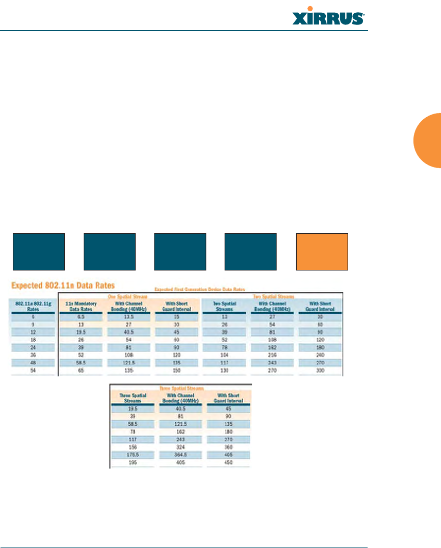
Wireless Array
Installing the Wireless Array 41
Obtaining Higher Data Rates
The data rate increase obtained by using 802.11n on an Array is incremental,
based on the technologies that are applied and the options that you select:
Higher encoding rates (Mandatory in 802.11n)
Spatial Streams (Mandatory, but multiplier varies directly with number of
streams selected.)
Channel Bonding (Mandatory in 802.11n, apply multiplier to IAP if it is
bonded.)
Short Guard Interval (Optional)
See Figure 21 to see the 802.11n data rate increase for an IAP. Apply this increase
to the 802.11 a, b or g data rates selected for the Array.
Figure 21. Computing 802.11n Data Rates
Optionally
Multiply By 2.077
to Bond
Two 20MHz
Channels
Optionally
Multiply by 1.11 for
Shorter Guard Interval
to Increase
Symbol Rate
Optionally
Multiply by 2, 3, 4
for the Number of
Additional
Spatial Streams
Choose New Base
Encoding + Modulation
BPSK (6.5)
QPSK (13, 19.5)
QAM-16 (26, 39)
QAM-64 (58.5, 65)
New 11n
Data Rate
xxx =
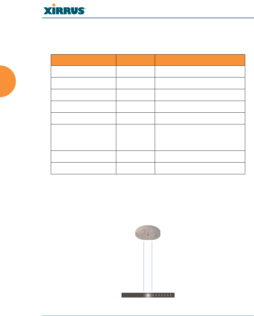
Wireless Array
42 Installing the Wireless Array
802.11n Capacity
802.11n offers major increases in capacity over previous 802.11 standards, as
shown in the table below.
Failover Planning
This section discusses failover protection at the unit and port levels. To ensure
that service is continued in the event of a port failure, you can utilize two Gigabit
Ethernet ports simultaneously as a bonded pair (on Arrays with two or more
Gigabit ports).
Figure 22. Port Failover Protection
802.11 Mode # Channels Max Theoretical Capacity
Fast Ethernet No Yes
802.11 a/n: 3 Streams 23 23 * 450 Mbps = 10.2 Gbps
802.11 a/n: 2 Streams 23 23 * 300 Mbps = 6.8 Gbps
802.11 a/n: 1 Stream 23 23 * 150 Mbps = 3.4 Gbps
802.11 a 23 23 * 54 Mbps = 1.2 Gbps
802.11 g/n: 3 Streams 3 3 * 450 Mbps = 1.35 Gbps
(1 or 2 streams have
proportionally lower capacity)
802.11 g 3 3 * 54 Mbps = 162 Mbps
802.11 b 3 3 * 11 Mbps = 33 Mbps
Ethernet switch
Multiple port connections

Wireless Array
Installing the Wireless Array 43
In addition, the Array has full failover protection between the bonded-pair
Gigabit ports (see following table).
The Wireless Array Gigabit Ethernet ports actually support a number of modes:
802.3ad Link Aggregation
Load Balancing
Broadcast
Link Backup
Mirrored
For more details on Gigabit port modes and their configuration, please see
“Network Bonds” on page 175.
Interface Bridges
Data?
Bridges
Management Traffic?
Fails Over
To: IP address
Fast
Ethernet No Yes None DHCP or static
Gigabit port Yes Yes Bonded
port DHCP or static
Bonded
Gigabit port Yes Yes Bonded
port Same
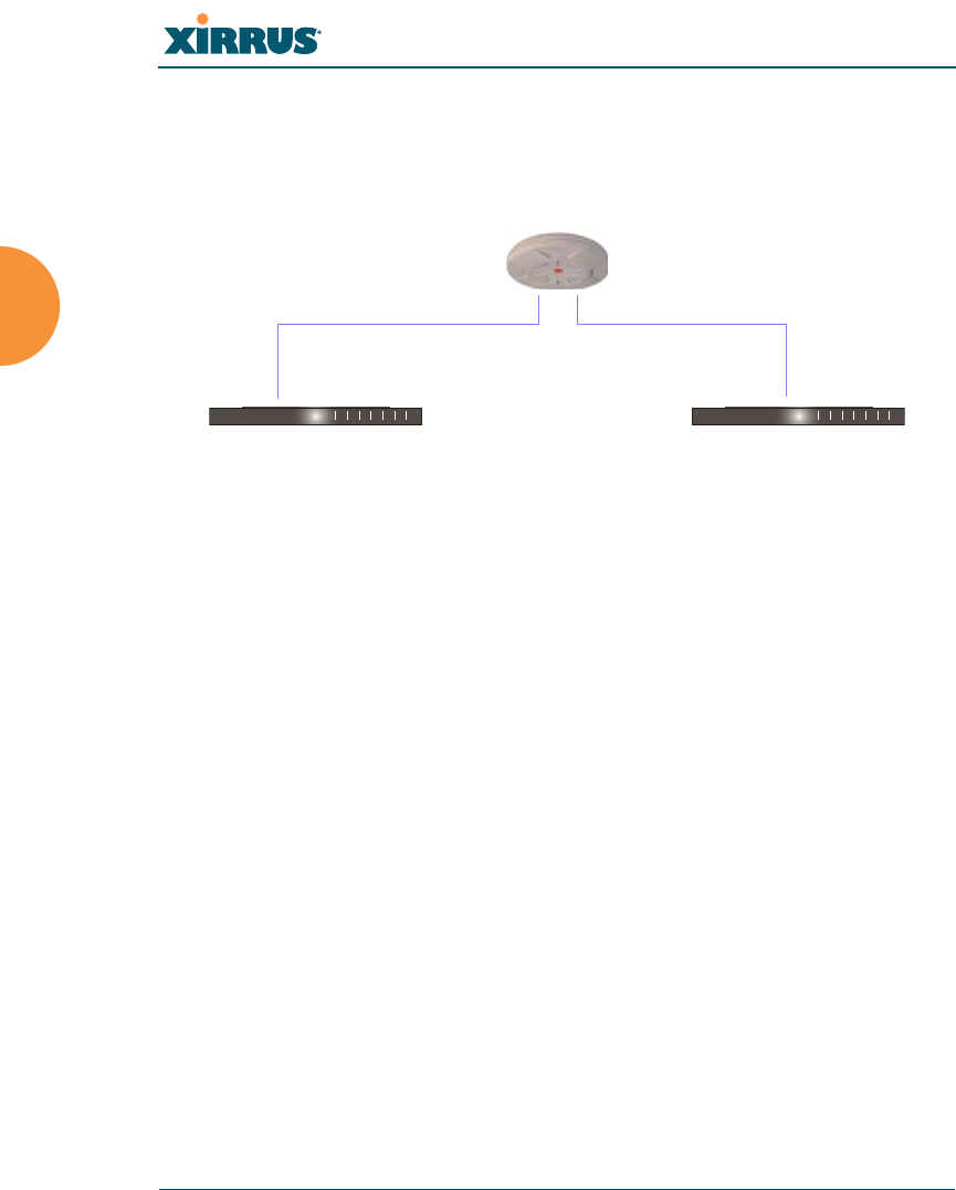
Wireless Array
44 Installing the Wireless Array
Switch Failover Protection
To ensure that service is continued in the event of a switch failure, you can
connect Arrays having multiple Gigabit ports to more than one Ethernet switch
(not a hub).
Figure 23. Switch Failover Protection
See Also
Coverage and Capacity Planning
Installation Prerequisites
Network Management Planning
Planning Your Installation
Power Planning
Security Planning
Gigabit Ethernet connections must be on the same subnet.
Ethernet switch Backup switch
Ethernet connections

Wireless Array
Installing the Wireless Array 45
Power Planning
All XR and XN Series Array models support Power over Gigabit Ethernet (PoGE)
with an integrated splitter. This section discusses PoGE power.
Power over Gigabit Ethernet
To deliver power to the Array, you must use Xirrus-supplied may use the optional
XP1, XP2, or XP8 Power over Gigabit Ethernet (PoGE) modules. They provide
power over Cat 5e or Cat 6 cables to the Array without running power cables —
see Figure 4 on page 12.
Specific models of the Array are compatible with specific PoGE modules. For
details, please see the Power over Gigabit Ethernet Installation and User Guide.
See Also
Coverage and Capacity Planning
Failover Planning
Network Management Planning
Security Planning
When using Cat 5e or Cat 6 cable, power can be provided up to a distance of
100m.

Wireless Array
46 Installing the Wireless Array
Security Planning
This section offers some useful guidelines for defining your preferred encryption
and authentication method. For additional information, see “Understanding
Security” on page 209 and the Security section of “Frequently Asked Questions”
on page 452.
Wireless Encryption
Encryption ensures that no user can decipher another user’s data transmitted
over the airwaves. There are three encryption options available to you, including:
WEP-40bit or WEP-128bit
Because WEP is vulnerable to cracks, we recommend that you only use
this for legacy devices that cannot support a stronger encryption type.
Wi-Fi Protected Access (WPA)
This is much more secure than WEP and uses TKIP for encryption.
Wi-Fi Protected Access (WPA2) with AES
This is government-grade encryption — available on most new client
adapters — and uses the AES–CCM encryption mode (Advanced
Encryption Standard–Counter Mode).
Authentication
Authentication ensures users are who they say they are, and occurs when users
attempt to join the wireless network and periodically thereafter. The following
authentication methods are available with the Wireless Array:
RADIUS 802.1x
802.1x uses a remote RADIUS server to authenticate large numbers of
clients, and can handle different authentication methods (EAP-TLS, EAP-
TTLS, EAP-PEAP, and EAP-LEAP Passthrough). Administrators may
Note that several advanced features in this section are part of the Xirrus
Advanced RF Security Manager (RSM). They require the license installed
on the Array to include support for RSM. Please see “About Licensing and
Upgrades” on page 361.

Wireless Array
Installing the Wireless Array 47
also be authenticated via RADIUS when preferred, or to meet particular
security standards.
Xirrus Internal RADIUS server
Recommended for smaller numbers of users (about 100 or less). Supports
EAP-PEAP only
Pre-Shared Key
Uses a pass-phrase or key that is manually distributed to all authorized
users. The same passphrase is given to client devices and entered into
each Array.
MAC Access Control Lists (ACLs)
MAC access control lists provide a list of client adapter MAC addresses
that are allowed or denied access to the wireless network, and can be
used in addition to any of the above authentication methods. ACLs are
good for embedded devices, like printers and bar-code scanners (though
MAC addresses can be spoofed). The Array supports 1,000 global ACL
entries. You may also define per-SSID access control lists, with up to 1000
entries each.
See Also
Failover Planning
Network Management Planning
Power Planning
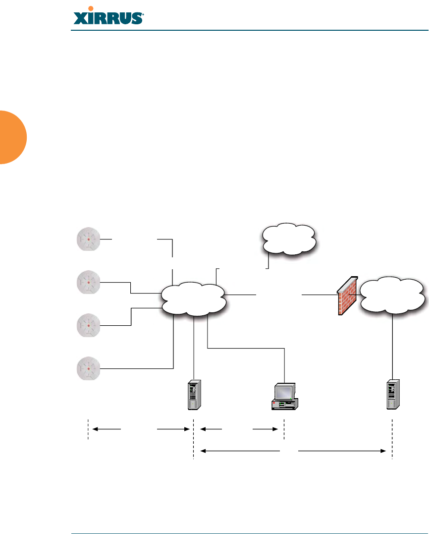
Wireless Array
48 Installing the Wireless Array
Port Requirements
A number of ports are used by various Array features and by the Xirrus
Management System (XMS). The Port Requirements table on page 49 lists ports
and the features that require them (XMS port requirements are included in the
table for your convenience). If you are using a feature, please make sure that the
ports that it requires are not blocked by firewalls or other policies, and that they
do not conflict with any other port assignments.
As an example, XMS port requirements are illustrated in Figure 24. XMS requires
ports 161, 162, and 443 to be passed between Arrays and the XMS server.
Similarly, ports 9090 and 9091 are required for communication between the XMS
server and XMS clients, and port 25 is typically used by the XMS server to access
an SMTP server to send email notifications.
Figure 24. Port Requirements for XMS
Firewall
XMS Server XMS Client*
L2 Switching
Infrastructure
SMTP Server*
Internal
Resources
External Network /
Internet
Ports:
9090, 9091
Ports:
161, 162, 443
SSID Traffic on
VLANs A, B, etc.
Management over
Native VLAN
Traffic from Arrays
VLAN B
Traffic from Arrays
VLAN A
Trunked 802.1q
VLAN Connection
Ports:
25
* XMS Client and SMTP Server may be internal or external resources.

Wireless Array
Installing the Wireless Array 49
The following table lists port requirements for the Array and for XMS, how they
are used, and whether they may be changed.
Port Application Peer Configurable
Array
icmp Ping XMS Server No
20 tcp
21 tcp FTP Client Yes
22 tcp SSH Client Yes
23 tcp Telnet Client Yes
25 tcp SMTP Mail Server No
69 udp TFTP TFTP Server No
123 udp NTP NTP Server No
161 udp SNMP XMS Server No
162 udp
SNMP Traphost Note -
Up to four Traphosts
may be configured.
XMS Server
Yes - but
required by
XMS
443 tcp HTTPS (WMI,WPR) Client Yes
514 udp Syslog Syslog Server No
1812, 1645
udp
RADIUS (some
servers use 1645) RADIUS Server Yes
1813, 1646
udp
RADIUS Accounting
(some servers still use
1646)
RADIUS Accounting
Server Yes
2055 udp Netflow Client Yes
5000 tcp Virtual Tunnel VTUN Server Yes
22610 udp XRP (Xirrus Roaming) Arrays Yes
22612 udp Xircon (Console Utility) Admin Workstation Yes

Wireless Array
50 Installing the Wireless Array
XMS
icmp Ping Arrays No
22 tcp SSH Arrays Yes
25 tcp SMTP Mail Server Yes
123 udp NTP NTP Server No
161 udp SNMP Arrays No
162 udp SNMP Traphost 1 Arrays Via XMS
config file
443 tcp HTTPS Arrays No
514 udp Resident Syslog server Internal* Via XMS
config file
1099 tcp RMI Registry Internal* No
2000 tcp XMS Back-end Server Internal* No
3306 tcp MySQL Database Internal* No
8001 tcp Status Viewer Internal* No
8007 tcp Tomcat Shutdown Internal* During
installation
8009 tcp Web Container Internal* During
installation
9090 tcp XMS Webserver XMS client During
installation
9091 tcp XMS Client Server XMS client Via XMS
config file
9092 tcp XMS Client Server XMS client Via XMS
config file
9443 tcp XMS WMI SSL XMS web client No
* Internal to XMS Server, no ports need to be unblocked on other network devices
Port Application Peer Configurable


Wireless Array
52 Installing the Wireless Array
Network Management Planning
Network management can be performed using any of the following methods:
Command Line Interface, using an SSH (Secure Shell) utility, like PuTTY.
The utility must be set up to use SSH-2, since the Array will only allow
SSH-2 connections.
Web-based management, using the Array’s embedded Web Management
Interface (WMI). This method provides configuration and basic
monitoring tools, and is good for small deployments (one or two units).
Centralized Web-based management, using the optional Xirrus
Management System (XMS), which can be run on a dedicated Xirrus
appliance or your own server. The XMS is used for managing large
Wireless Array deployments from a centralized Web-based interface and
offers the following features:
Globally manage large numbers of Arrays (up to 500)
Seamless view of the entire wireless network
Easily configure large numbers of Arrays
Rogue AP monitoring
Easily manage system-wide firmware updates
Monitor performance and trends
Aggregation of alerts and alarms
See Also
Failover Planning
Power Planning
Security Planning
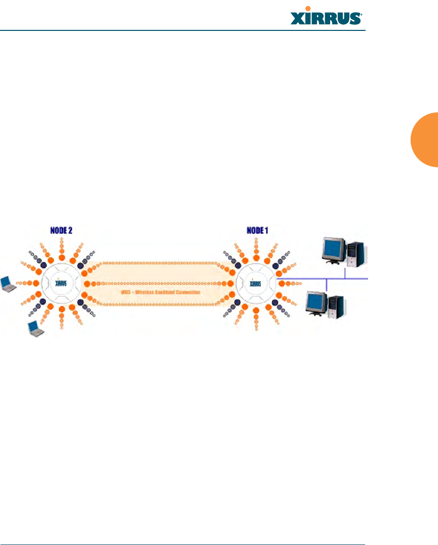
Wireless Array
Installing the Wireless Array 53
WDS Planning
WDS (Wireless Distribution System) creates wireless backhauls between Arrays,
allowing your wireless network to be expanded using multiple Arrays without
the need for a wired backbone to link them (see Figure 25). WDS features include:
One to three IAPs may be used to form a single WDS link, yielding up to
1350 Mbps bandwidth per link. Up to three different WDS links may be
created on a single Array.
Automatic IAP Load Balancing
If desired, you may allow clients to associate to a BSS on the same radio
interface used for a WDS Host Link. This will take bandwidth from the
WDS link.
Figure 25. WDS Link
Multiple links per Array allow you to configure multi-hop connections.
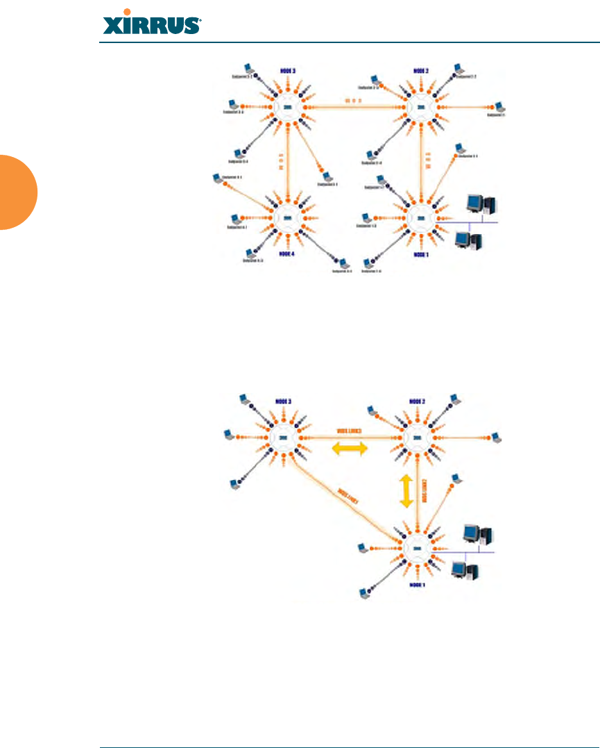
Wireless Array
54 Installing the Wireless Array
Figure 26. A Multiple Hop WDS Connection
Multiple WDS links can provide link redundancy (failover capability - see
Figure 27). A network protocol (Spanning Tree Protocol — STP) prevents
Arrays from forming network loops.
Figure 27. WDS Failover Protection

Wireless Array
Installing the Wireless Array 55
WDS links have a Host/Client relationship similar to the usual IAP/station
pattern for Arrays:
A WDS Client Link associates/authenticates to a host (target) Array in the
same way that a station associates to an IAP. The client side of the link
must be configured with the root MAC address of the target (host) Array.
A WDS Host Link acts like an IAP by allowing one WDS Client Link to
associate to it. An Array may have both client and host links.
WDS configuration is performed only on the client-side Array. See “WDS” on
page 338. Note that both Arrays must be configured with the same SSID name.

Wireless Array
56 Installing the Wireless Array
Common Deployment Options
The following table lists some typical and recommended deployment options for
a number of the features that have been discussed in this chapter.
See Also
Coverage and Capacity Planning
Network Management Planning
Planning Your Installation
Power Planning
Security Planning
Function Number of Wireless Arrays
One or Two Three or More
Power Power over Gigabit
Ethernet Power over Gigabit Ethernet
UPS backup
(recommended)
Failover Recommended Highly recommended
VLANs Optional Optional use,
Can be used to put all APs
on one VLAN or map to
existing VLAN scheme
Encryption WPA2 with AES
(recommended)
PSK or 802.1x
WPA2 with AES
(recommended)
802.1x keying
Authentication Internal RADIUS server
EAP-PEAP
Pre-Shared Key
External RADIUS server
Management Internal WMI
Internal CLI (via SSHv2)
XMS (SNMP)

Wireless Array
Installing the Wireless Array 57
Installation Workflow
This workflow illustrates the steps that are required to install and configure your
Wireless Array successfully. Review this flowchart before attempting to install the
unit on a customer’s network.
Figure 28. Installation Workflow
See Also
Coverage and Capacity Planning
Common Deployment Options
Determine the number of Arrays needed
Choose the location(s) for your Wireless Arrays
Install the mounting plate
Connect the cables and turn on the power
Verify that the Ethernet link and radio LEDs are functioning correctly
Perform the Express Setup procedure
Run Ethernet cables for PoGE
(<100m total distance from switch)
Log in to WMI and enter your license

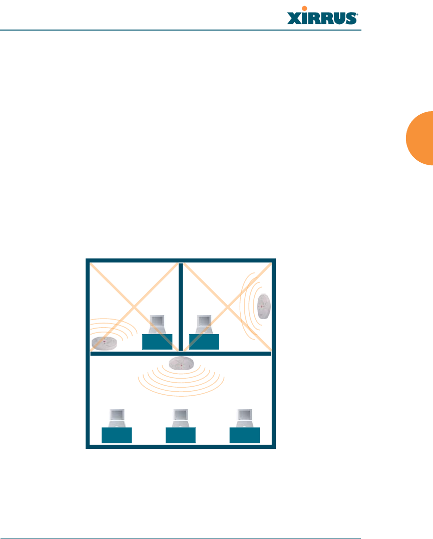
Wireless Array
Installing the Wireless Array 59
Installing Your Wireless Array
This section provides instructions for completing a physical installation of your
Xirrus Wireless Array.
Choosing a Location
Based on coverage, capacity and deployment examples previously discussed,
choose a location for the Array that will provide the best results for your needs.
The Wireless Array was designed to be mounted on a ceiling where the unit is
unobtrusive and wireless transmissions can travel unimpeded throughout open
plan areas.
You also have the option of mounting the Array on a wall, using the optional wall
mount assembly kit.
Choose a location that is central to your users (see the following diagram for
correct placement.
Figure 29. Array Placement
Wiring Considerations
Before using the Xirrus-supplied Power over Gigabit Ethernet modules (PoGE) to
distribute power, see “Power over Gigabit Ethernet (PoGE)” on page 12.
WR
ONG
CORRECT
R
ORRE
R
ORREC
WR
ONG
G
G
O
ON
R
O
R
ON
ON
R
O
R
ON

Wireless Array
60 Installing the Wireless Array
Once you have determined the best location for your Wireless Array, you must
run cables to the location for the following services:
Power
No separate power cable to the Array is required when using
PoGE modules. The PoGE module requires a dedicated AC
power outlet (100 - 240 VAC).
Network
Gigabit POE1 — If using PoGE modules, the total of all Cat 5e or
Cat 6 cable segments from the Gigabit Ethernet switch to an
Array Ethernet port must be less than 100m long. The Array must
be connected to PoGE networks without routing cabling to the
outside plant, to ensure that cabling is not exposed to lightning
strikes or possible high voltage crossover.
Gigabit POE2—For Arrays with a second POE port, the same
restrictions listed above apply.(optional, not available on the
four-port Arrays)
Fast Ethernet (optional, not available on the four-port Arrays)
Serial cable (optional) — cable lengths up to 25’ per the RS-232
specification.
Important Notes About Network Connections
Read the following notes before making any network connections.
When the unit’s IP address is unknown or a network connection has not
been established, the serial cable is used for connecting directly with the
Command Line Interface (CLI) via HyperTerminal. When a network
connection is established, the Array can be managed from any of the
available network connections, either Fast Ethernet, Gigabit 1 or Gigabit 2.
For the XR-1000, the Xirrus Xircon utility may be used locally to set up an
IP address if necessary.

Wireless Array
Installing the Wireless Array 61
See Also
Failover Planning
Installation Prerequisites
Installation Workflow
Mounting the Array
Power over Gigabit Ethernet (PoGE)
!The Array’s Ethernet ports should be plugged into an Ethernet switch, not an
Ethernet hub — if a hub is used, we recommend that you connect only one
Ethernet port.
!The Gigabit1 Ethernet interface is the primary port for both data and
management traffic. If a single Ethernet connection is used, it must be
connected to the Gigabit1 Ethernet interface. See also, “Failover Planning” on
page 42.
The 10/100 Ethernet Port may be used for managing the Array out of band
from the Gigabit Ethernet ports. The 10/100 port will route only management
traffic, using a static route that may be configured for this interface. See
“interface” on page 407.

Wireless Array
62 Installing the Wireless Array
Mounting the Array
A number of options are available for mounting Arrays:
Ceiling mount
Wall mount
Secure mount in a locking indoor enclosure
I-Beam mount in a protective enclosure (gymnasium mount)
Factory enclosure
A detailed Quick Installation Guide is provided with the mounting option that
you selected when ordering your Array. Please follow the provided instructions
carefully.
Dismounting the Array
To dismount any other Array model
For all Array models, push up on the Array (i.e., push it against the mounting
plate). Then turn the Array to the left to remove it. This is similar to dismounting
a smoke detector.
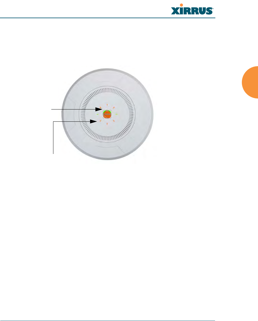
Wireless Array
Installing the Wireless Array 63
Powering Up the Wireless Array
When powering up, the Array follows a specific sequence of LED patterns
showing the boot progress, and following a successful boot will provide extensive
status information.
Figure 30. LED Locations
Array LED settings may be altered or disabled entirely for diagnostic purposes or
for personal preference. Changes are made via the Array’s Command Line
Interface or the Web Management Interface — refer to “LED Settings” on page 334.
Ethernet Activity
and Status LEDs
IAP LEDs

Wireless Array
64 Installing the Wireless Array
Array LED Operating Sequences
Use the following tables to review the operating sequences of the Array’s LEDs.
“LED Boot Sequence” on page 64
“LED Operation when Array is Running” on page 65
LED Boot Sequence
The normal boot LED sequence is as follows:
Array Activity Status LED IAP LEDs
Power ON Blinking GREEN All OFF
Boot loader power ON
self-test
Blinking GREEN All ON
Image load from
compact FLASH
Blinking GREEN Spinning pattern (rotate all
to ON, then all to OFF)
Image load failure Blinking ORANGE All OFF
Hand off to ArrayOS Solid GREEN All OFF
System software
initialization
Solid GREEN Walking pattern — (LED
rotating one position per
second)
Up and running Solid ON ON for IAPs that are up:
OFF for IAPs that are down.
Green or orange per table on
the next page.
Behavior may be changed
using “LED Settings” on
page 334.

Wireless Array
Installing the Wireless Array 65
LED Operation when Array is Running
The normal LED operation when the Array is running is shown in the table
below. Note that behavior may be modified using “LED Settings” on page 334 or
via the CLI.
See Also
Installation Prerequisites
Installation Workflow
Installing Your Wireless Array
LED Settings
LED Status Reason
IAP LED is OFF IAP is down
IAP LED is solid ON IAP is up, but no associations and
no traffic
IAP LED heartbeat IAP is up, with stations
associated but no traffic
IAP LED flashing
Flashing at 10 Hz
Flashing at 5 Hz
Flashing at 2.5 Hz
IAP is up, passing traffic
Traffic > 1500 packets/sec
Traffic > 150 packets/sec
Traffic > 1 packet/sec
IAP LED is GREEN IAP is operating in the 2.4 GHz
band
IAP LED is ORANGE IAP is operating in the 5 GHz
band
IAP LED flashing ORANGE to
GREEN at 1 Hz
The radio is in monitor mode
(standard intrude detect)
Ethernet LEDs are dual color
Ethernet LED is ORANGE
Ethernet LED is GREEN
Transferring data at 1 Gbps
Transferring data at 10/100 Mbps
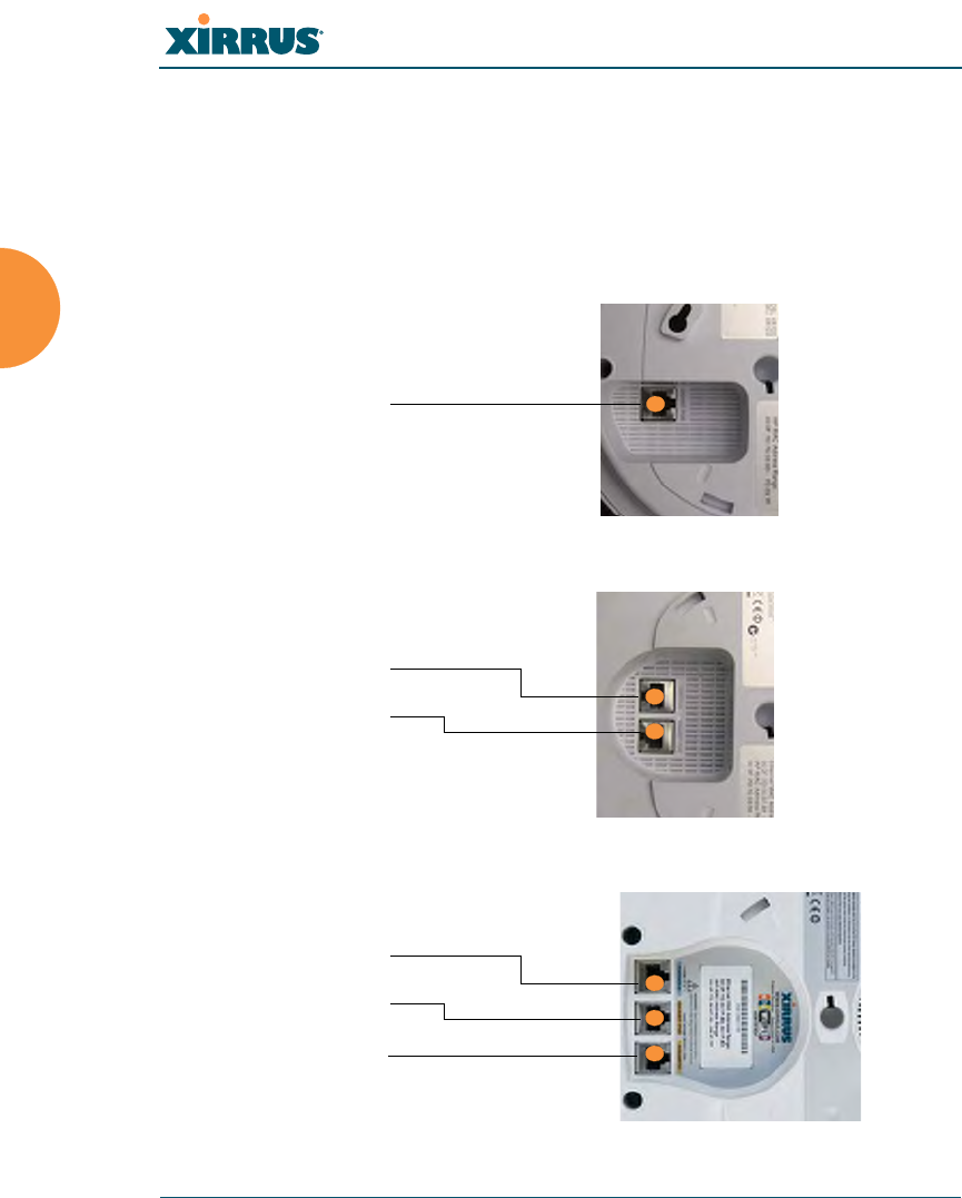
Wireless Array
66 Installing the Wireless Array
Establishing Communication with the Array
The Array may be configured through the Command Line Interface (CLI) using
SSH, or on a browser via the graphical Web Management Interface (WMI). You
may use the CLI via the serial management port (console—on all Arrays except
the XR500 and XR-1000 Series), the Fast Ethernet port, or any of the Gigabit
Ethernet ports. You can use the WMI via any of the Array’s Ethernet ports.
Figure 31. Network Interface Ports—XR-1000 Series
Figure 32. Network Interface Ports—XR-2000 Series
Figure 33. Network Interface Ports—XR-4000 Series
Gigabit POE (gig1)
Serial (Console)
Gigabit POE (gig1)
Serial (Console)
Gigabit POE (gig1)
Gigabit 2 (gig2)
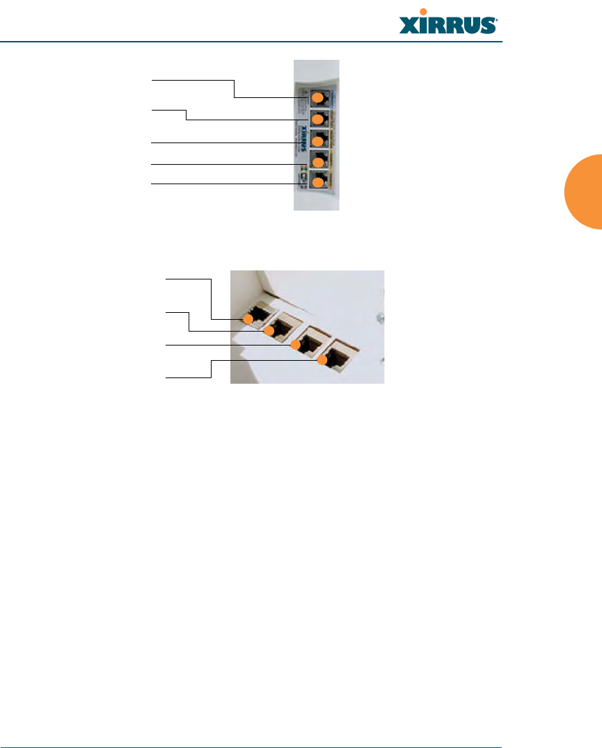
Wireless Array
Installing the Wireless Array 67
Figure 34. Network Interface Ports—XR-6000 Series
Figure 35. Network Interface Ports
Using the Serial Port
If using the serial port to make your connection, use serial settings of 8 bits, no
parity, no flow control, 1 stop bit (8N1) and a speed setting of 115200 baud. Use
the communication package of your choice.
Using the Ethernet Ports
By default, the Array's Ethernet interfaces use DHCP to obtain an IP address. If
the Array is booted and does not receive DHCP addresses on either the Fast
Ethernet or Gigabit Ethernet ports, then the Fast Ethernet port will default to an
The Xirrus Xircon utility may also be used to communicate with Arrays
locally as an alternative to using a serial connection to the console. This is
especially useful for the XR500 and XR-1000 Series, which do not have a
console port. See “Securing Low Level Access to the Array” on page 78.
Serial (Console)
Gigabit POE1 (gig1)
Gigabit POE2 (gig2)
Gigabit 3 (gig3)
Gigabit 4 (gig4)
Serial
Fast Ethernet
Gigabit 1
Gigabit 2

Wireless Array
68 Installing the Wireless Array
IP address of 10.0.1.1 and both Gigabit1 and its bonded pair port (if any) will
default to 10.0.2.1 with a mask of 255.255.255.0.
If the Array is connected to a network that provides DHCP addresses, the IP
address can be determined by the following three methods:
1. The simplest way to address the Array is using its default hostname
which is the Array’s serial number (for example,
XR4012N0823091CACD). If your network provides DHCP and DNS, then
you can use this hostname.
2. Otherwise, examine the DHCP tables on the server and find the addresses
assigned to the Array (Xirrus MAC addresses begin with 000F7D).
3. Alternatively, you may query the Array using the CLI via the console port
(on all models except the wall-1000 series). Log in using the default user
name admin and password admin. Use the show ethernet command to
view the IP addresses assigned to each port.
4. If the Array cannot obtain an IP address via DHCP, the factory default
uses a static IP address of 10.0.2.1 with a mask of 255.255.255.0 on its
Gigabit POE port.
To connect to the Array, you must set your laptop to be in the same
subnet as the Array: set your laptop’s IP address to be in the 10.0.2.xx
subnet, and set its subnet mask to 255.255.255.0. If this subnet is already
in use on your network, you may connect your laptop directly to the
Array by connecting the laptop to the power injector’s IN port
temporarily (this port may be called the SWITCH port or the DATA port
on your injector).
Take care to ensure that your network is not using the 10.0.2.1 IP address
prior to connecting the Array to the network.

Wireless Array
Installing the Wireless Array 69
Starting the WMI
Use this procedure to log in to the WMI via your Web browser.
1. Establish a network connection and open your Web browser.
2. Connect to the Wireless Array using its host name or IP address as
described in the previous section.
Logging In
When logging in to the Array, use the default user name and password — the
default user name is admin, and the default password is admin.
See Also
Installation Workflow
Performing the Express Setup Procedure
Powering Up the Wireless Array
Entering the License
A license is needed to enable the full functionality of the Array. Without a license,
the Array can be powered up and will only have a basic wireless network
configuration including just one operating radio.
The Array’s license determines many of the features that are available on the
Array. For example, automatic cell sizing and channel allocation require a license
supporting the RF Performance Manager (RPM). Also, IEEE 802.11n operation on
Arrays requires a license.
The Array’s license is not installed at the factory. You must enter your license
before proceeding to the next step, Performing the Express Setup Procedure.
The procedure below describes entering the license key using the WMI. If you are
using the Xirrus Management System (XMS), you may use it to easily manage and
upgrade large numbers of licenses for the wireless network.
1. This procedure assumes that you have pointed a browser to the Array’s
IP address to start WMI, and that you have logged in with the default
username and password above.

Wireless Array
70 Installing the Wireless Array
2. In the left hand frame, in the Configuration section, click Express Setup.
3. License Key: Enter the key that was provided for the Array. The key was
provided to you in an email as an attachment in the form of an Excel file
(.xls). Enter the key exactly as it appears in the file. Click the Apply
button to apply the key.
4. Now you may verify the features provided by the key. In the Status
section of the left hand frame, click Array and then click Information.
Check the items listed in the License Features row.
If you are installing a large number of licenses and do not have XMS, a
Xirrus Licensing Tool may be acquired from Xirrus Support to help push
licenses to large number of Arrays.
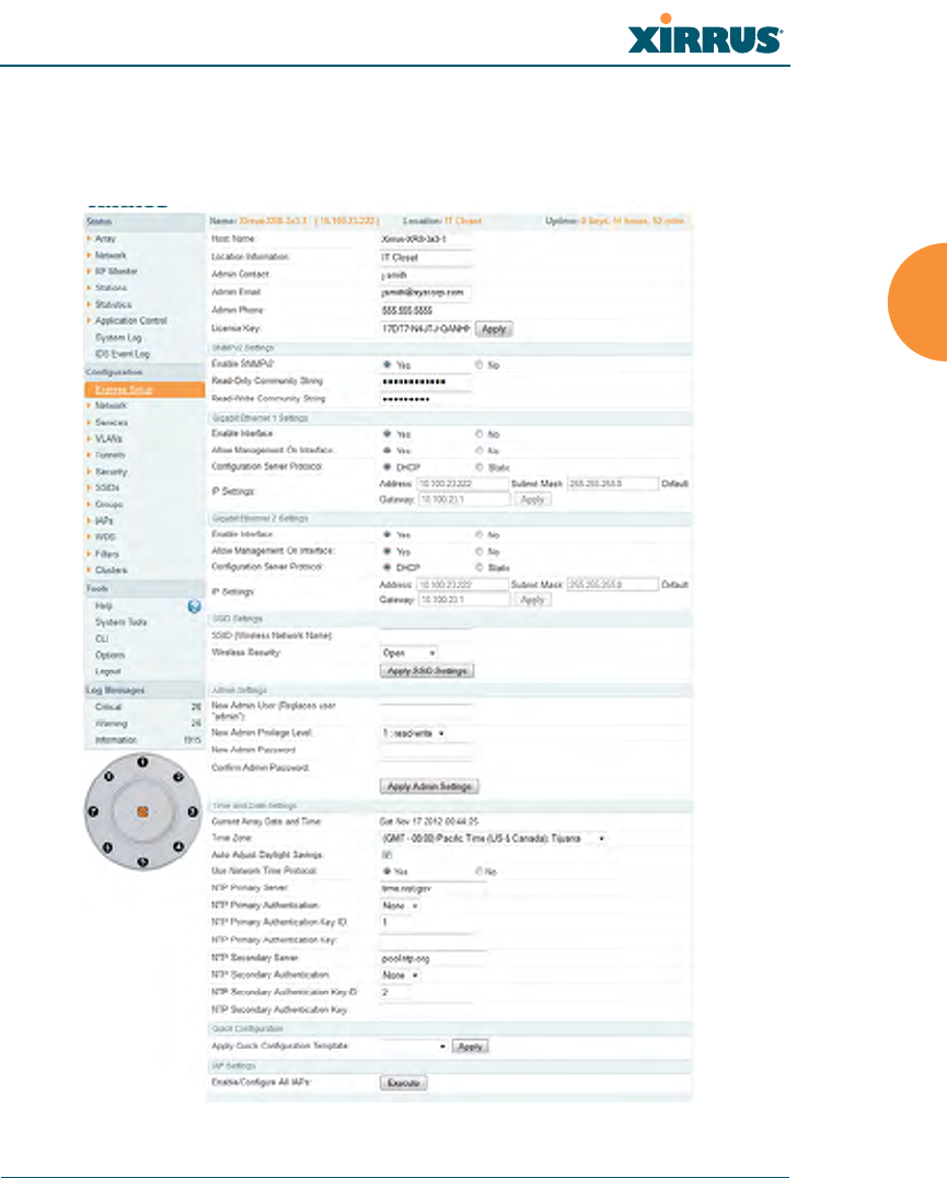
Wireless Array
Installing the Wireless Array 71
Performing the Express Setup Procedure
The Express Setup procedure establishes global configuration settings that enable
basic Array functionality. Changes made in this window will affect all radios.
Figure 36. Express Setup

Wireless Array
72 Installing the Wireless Array
Procedure for Performing an Express Setup
1. Host Name: Specify a unique host name for this Array. The host name is
used to identify the Array on the network. Use a name that will be
meaningful within your network environment, up to 64 alphanumeric
characters. The default is Xirrus-WiFi-Array.
2. Location Information: Enter a brief but meaningful description that
accurately defines the physical location of the Array. In an environment
where multiple units are installed, clear definitions for their locations are
important if you want to identify a specific unit.
3. Admin Contact: Enter the name and contact information of the person
who is responsible for administering the Array at the designated location.
4. Admin Email: Enter the email address of the admin contact you entered
in Step 3.
5. Admin Phone: Enter the telephone number of the admin contact you
entered in Step 3.
6. License Key: If Xirrus issued you a license that differs from the current
value shown, enter it now. See also, “Entering the License” on page 69.
7. Configure SNMPv2: Select whether to Enable SNMPv2 on the Array, and
change the SNMP Community Strings if desired. If you are using the
Xirrus Management System (XMS), these strings must match the values
used by XMS. The default values for the Array match the defaults in
XMS. For more details, including SNMPv3, see “SNMP” on page 194.
8. Configure the Fast Ethernet (10/100 Megabit) and Gigabit network
interfaces. The fields for each of these interfaces are the same, and
include:
a. Enable Interface: Choose Yes to enable this network interface, or
choose No to disable the interface.
b. Allow Management on Interface: Choose Yes to allow management
of the Array via this network interface, or choose No to deny all
management privileges for this interface.

Wireless Array
Installing the Wireless Array 73
c. Configuration Server Protocol: Choose DHCP to instruct the Array
to use DHCP to assign IP addresses to the Array’s Ethernet interfaces,
or choose Static if you intend to enter IP addresses manually. If you
choose the Static IP option, you must enter the following IP Settings:
Address: Enter a valid IP address for this Array. To use any of the
remote connections (Web, SNMP, or SSH), a valid IP address
must be used.
Subnet Mask: Enter a valid IP address for the subnet mask (the
default is 255.255.255.0). The subnet mask defines the number of
IP addresses that are available on the routed subnet where the
Array is located.
Default Gateway: Enter a valid IP address for the default
gateway. This is the IP address of the router that the Array uses
to forward data to other networks.
Click the Apply button for this interface when done making IP
changes.
9. SSID Settings: This section specifies the wireless network name and
security settings.
a. SSID (Wireless Network Name): The SSID (Service Set Identifier) is
a unique name that identifies a wireless network. All devices
attempting to connect to a specific WLAN must use the same SSID.
The default for this field is “xirrus.”
For additional information about SSIDs, go to the Multiple SSIDs
section of “Frequently Asked Questions” on page 452.
b. Wireless Security: Select the desired wireless security scheme (Open,
WEP, WPA, WPA2, or WPA-Both). WPA2 is recommended for the
best Wi-Fi security.
•Open — This option offers no data encryption and is not
recommended, though you might choose this option if clients are
For improved security, you should also take the additional steps described in
“Securing Low Level Access to the Array” on page 78.

Wireless Array
74 Installing the Wireless Array
required to use a VPN connection through a secure SSH utility,
like PuTTy.
•WEP (Wired Equivalent Privacy) — An optional IEEE 802.11
function that offers frame transmission privacy similar to a wired
network. WEP generates secret shared encryption keys that both
source and destination stations can use to alter frame bits to
avoid disclosure to eavesdroppers.
•WPA (Wi-Fi Protected Access) — A Wi-Fi Alliance standard that
contains a subset of the IEEE 802.11i standard, using TKIP or AES
as an encryption method and 802.1x for authentication.
•WPA2 (Wi-Fi Protected Access 2) — WPA2 is the follow-on
security method to WPA for wireless networks and provides
stronger data protection and network access control. It offers
Enterprise and consumer Wi-Fi users with a high level of
assurance that only authorized users can access their wireless
networks. Like WPA, WPA2 is designed to secure all versions of
802.11 devices, including 802.11a, 802.11b, 802.11g, and 802.11n,
multi-band and multi-mode.
•WPA-Both (WPA and WPA2) — This option makes use of both
WPA and WPA2.
For more information about security, including a full review of all
security options and settings, go to “Understanding Security” on
page 209.
c. WEP Encryption Key/Passphrase: Depending on the wireless
security scheme you selected, enter a unique WEP key or WPA
passphrase. This field and the one below only appear if you select a
Wireless Security option other than Open.
d. Confirm Encryption Key/Passphrase: If you entered a WEP key or
WPA passphrase, confirm it here.
e. Click Apply SSID Settings when done.

Wireless Array
Installing the Wireless Array 75
10. Admin Settings: This section allows you to change the default admin
username, password, and privileges for the Array. You may change the
password and leave the user name as is, but we suggest that you change
both to improve Array security.
a. New Admin User (Replaces user “admin”): Enter the name of a new
administrator user account. Be sure to record the new account name
and password, because the default admin user will be deleted! Note
that the Array also offers the option of authenticating administrators
using a RADIUS server (see “Admin Management” on page 214)).
b. New Admin Privilege Level: By default, the new administrator will
have read/write privileges on the Array (i.e., the new user will be
able to change the configuration of the Array). If you wish the new
account to have different privileges, select the desired level from the
drop-down list. For more information about user privileges, please
see “Admin Privileges” on page 216.
c. New Admin Password: Enter a new administration password for
managing this Array. If you forget this password, you must reset the
Array to its factory defaults so that the password is reset to admin (its
default setting).
d. Confirm Admin Password: If you entered a new administration
password, confirm the new password here.
e. Click Apply Admin Settings when done.
11. Time and Date Settings: This section specifies an optional time (NTP -
Network Time Protocol) server or modifies the system time if you’re not
using a server.
a. Current Array Date and Time: This read-only field shows the current
time for your convenience.
For improved security, you should also take the additional steps described in
“Securing Low Level Access to the Array” on page 78.

Wireless Array
76 Installing the Wireless Array
b. Time Zone: Select your time zone from the choices available in the
pull-down list.
c. Auto Adjust Daylight Savings: If you are not using NTP, check this
box if you want the system to adjust for daylight savings
automatically, otherwise leave this box unchecked (default).
d. Use Network Time Protocol: Check this box if you want to use an
NTP server to synchronize the Array’s clock. Use of NTP is
mandatory for Arrays to be managed with XMS (the Xirrus
Management System), and ensures that Syslog time-stamping is
maintained across all units. If you check Yes, the NTP server fields
are displayed. If you don’t want to use an NTP server, leave this box
unchecked (default) and set the system time on the Array manually.
e. NTP Primary Server: If you are using NTP, enter the IP address or
domain name of the NTP server.
f. NTP Primary Authentication: If you are using authentication with
NTP, select the type of key: MD5 or SHA1. Select None if you are not
using authentication (this is the default). For more information on
authenticated NTP, see “Time Settings (NTP)” on page 185.
g. NTP Primary Authentication Key ID: Enter the key ID, which is a
decimal integer.
h. NTP Primary Authentication Key: Enter your key, which is a string
of characters.
i. NTP Secondary Server: Enter the IP address or domain name of an
optional secondary NTP server to be used in case the Array is unable
to contact the primary server. You may use the authentication fields
as described above if you wish to set up authentication for the
secondary server.
j. Adjust Time (hrs:min:sec): If you are not using NTP, check this box if
you want to adjust the current system time. When the box is checked,
the time fields become active. Enter the revised time (hours, minutes,

Wireless Array
Installing the Wireless Array 77
seconds, am/pm) in the corresponding fields. If you don’t want to
adjust the current time, this box should be left unchecked (default).
k. Adjust Date (month/day/year): If you are not using NTP, check this
box if you want to adjust the current system date. When the box is
checked, the date fields become active. Enter the revised date (month,
day and year) in the corresponding fields. If you don’t want to adjust
the current date, this box should be left unchecked (default).
12. Quick Configuration: This offers predefined configuration options such
as Classroom and High-Density that capture best practices from years of
field experience. If one of the options in the drop-down list is appropriate
to your deployment, select it and click Apply. For example, the High-
Density option uses best practices to configure the Array for high density
settings such as lecture halls, convention centers, stadiums, etc.
13. IAP Settings:
Enable/Configure All IAPs: Click on the Execute button to enable and
auto configure all IAPs (a message displays the countdown time — in
seconds — to complete the auto-configuration task). When an IAP is
enabled, its LED is switched on. (Figure 37, see also “Array LED
Operating Sequences” on page 64.)
Figure 37. LEDs are Switched On
LED on

Wireless Array
78 Installing the Wireless Array
14. Click on the Save changes to flash button at the top right if you wish to
make your changes permanent.
This ends the Express Setup procedure.
See Also
Establishing Communication with the Array
Installation Prerequisites
Installation Workflow
Logging In
Multiple SSIDs
Security
Securing Low Level Access to the Array
Most management of the Xirrus Array is done via the Web Management Interface
(WMI) as you just saw in “Performing the Express Setup Procedure” on page 71.
Another often used option is CLI—see “The Command Line Interface” on
page 377. The Array also has a lower level interface: XBL (Xirrus Boot Loader),
which allows access to more primitive commands. You won’t normally use XBL
unless instructed to do so by Xirrus Customer Support. For proper security, you
should replace the default XBL login username and password with your own, as
instructed below. XBL has its own username and password, separate from the
ArrayOS Admin User and Password (used for logging in to the WMI and CLI)
that you changed in Step 10 on page 75.
Xirrus also provides the Xircon utility for connecting to Xirrus XR Arrays that are
not reachable via the normal access methods (such as SSH or WMI) and that do
not have a physical console port (XR500 and XR-1000 Series Arrays), or whose
console port is not accessible. Xircon discovers Arrays on your network subnet
by sending IP/UDP broadcast packets. Once an Array is discovered, Xircon can
establish an encrypted console session to the Array via the network even if the
Array IP configuration is incorrect. Xircon allows you to manage the Array using
CLI, just as you would if connected to the console port. Xircon also has an option
for easily accessing XBL.

Wireless Array
Installing the Wireless Array 79
In normal circumstances Xirrus Arrays should be configured and managed
through secure shell (SSH) or via the Web Management Interface (WMI). A
connection is established using either the Array hostname or DHCP-assigned IP
address, or via the other options described in “Using the Ethernet Ports” on
page 67. Xircon may be needed in special circumstances as directed by Xirrus
Customer Support for troubleshooting Array problems or IP connectivity. (In this
case, see the Xircon User Guide for detailed information.)
Xircon access to the Array may be controlled:
You may enable or disable all Xircon access to the Array as instructed in
the procedure below. There are also options to allow access only to CLI
(i.e., ArrayOS access) or only to XBL.
Since XR500 and XR-1000 Array models do not have a console port, these
models have Xircon access to both XBL and CLI enabled by default. For
Arrays that do not have a console port, to avoid potentially being locked
out of the Array, Xircon should always be enabled at the XBL level at
least.
On all other Array models (those with a console port), Xircon access to
both XBL and CLI is disabled by default. If Xircon is not going to be used
to access an Array, we recommend leaving Xircon access disabled.
Procedure for Securing Low Level Array Access
Use the following steps to replace the default XBL username and password, and
optionally to change the type of Xircon management access that is allowed. These
steps use CLI commands.
!If you disable Xircon access to both XBL and CLI on XR-1000 models, you
must ensure that you do not lose track of the username and password to log in
to CLI/WMI! In this situation, there is no way to recover from a lost password,
other than returning the Array to Xirrus. If you have Xircon access to XBL
enabled, you can reset the password, but this recovery will require setting the
unit to factory defaults with loss of all configuration data.

Wireless Array
80 Installing the Wireless Array
1. To access CLI via the WMI, click CLI under the Tools section on the left
(for detailed instructions see “CLI” on page 371). Skip to Step 4 on
page 80.
To access CLI via SSH, see “Establishing a Secure Shell (SSH)
Connection” on page 377. Then proceed to the next step.
2. At the login as prompt, log in to CLI using the username and password
that you set in Step 10 on page 75.
login as: jsmith
jsmith@xr4012802207c's password:
Xirrus Wi-Fi Array
ArrayOS Version 6.1.2-3299
Copyright (c) 2005-2012 Xirrus, Inc.
http://www.xirrus.com
XR4012802207C#
3. Type configure to enter the CLI config mode.
hostname#configure
4. If Xircon access at the XBL level is to be allowed, use the following three
commands to change the XBL username and password from the default
values of admin/admin. In the example below, replace newusername
and newpassword with your desired entries. Note that these entries are
case-sensitive.
(config)#boot-env set username newusername
(config)#boot-env set password newpassword
(config)#save
5. Enter the following commands if you wish to change Xircon access
permission:
(config)# management
(config-mgmt)# xircon <management-status>
(config-mgmt)# save
(config-mgmt)# exit
(config)#
<management-status> may be one of :
on enables both CLI and XBL access

Wireless Array
Installing the Wireless Array 81
off disables both CLI and XBL access
aos-only enables only CLI (i.e. ArrayOS) access
boot-only enables only XBL access
Note that there is a WMI setting for changing Xircon access, timeout
period, and the UDP port used. This may be used instead of CLI if you
wish. See “Management Control” on page 221. Note that you cannot
change the XBL username and password via the WMI.

Wireless Array
82 Installing the Wireless Array

Wireless Array
The Web Management Interface 83
The Web Management Interface
This topic provides an overview of the Xirrus Wireless Array’s embedded Web
Management Interface (WMI), used for establishing your network’s configuration
settings and wireless operating parameters. It also includes login instructions.
The following topics are discussed:
An Overview
Structure of the WMI
User Interface
Logging In
Applying Configuration Changes
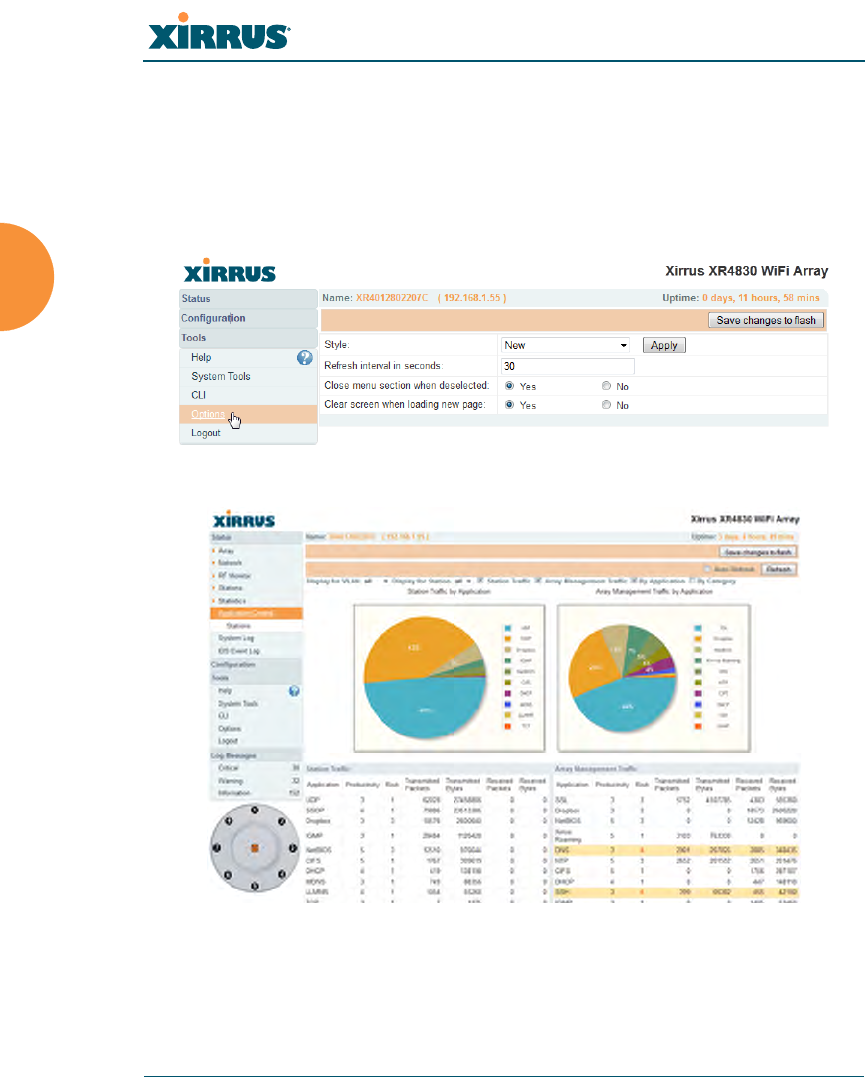
Wireless Array
84 The Web Management Interface
An Overview
The WMI is an easy-to-use graphical interface to your Wireless Array. It allows
you to configure the product to suit your individual requirements and ensure that
the unit functions efficiently and effectively. Options allow you to choose among
different appearances for the WMI. See “Options” on page 373.
Figure 38. Web Management Interface—Option = New Style
Figure 39. Web Management Interface—New Style
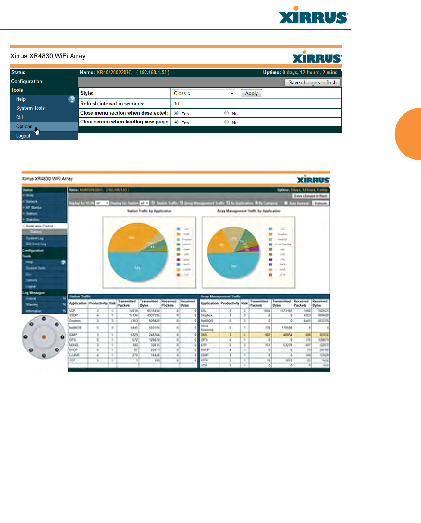
Wireless Array
The Web Management Interface 85
Figure 40. Web Management Interface—Option = Classic Style
Figure 41. Web Management Interface—Classic Style

Wireless Array
86 The Web Management Interface
Structure of the WMI
The content of the WMI is organized by function and hierarchy, shown in the
following table. Click on any item below to jump to the referenced destination.
Status Windows
Array Status Windows
Array Summary
Array Information
Array Configuration
Admin History
Network Status Windows
Network Map
Spanning Tree Status
Routing Table
ARP Table
DHCP Leases
Connection Tracking/NAT
CDP Neighbors
Network Assurance
RF Monitor Windows
IAPs
Spectrum Analyzer
Intrusion Detection
Channel History
Radio Assurance
Station Status Windows
Stations
Location Map
RSSI
Signal-to-Noise Ratio (SNR)
Noise Floor
Max by IAP
Station Assurance
Statistics Windows
IAP Statistics Summary
Per-IAP Statistics
Network Statistics
VLAN Statistics
WDS Statistics
IDS Statistics
Filter Statistics
Station Statistics
Per-Station Statistics
Application Control Windows
System Log Window
IDS Event Log Window

Wireless Array
The Web Management Interface 87
Configuration Windows
Express Setup
Network
Network Interfaces
Network Bonds
DNS Settings
CDP Settings
Services
Time Settings (NTP)
NetFlow
Wi-Fi Tag
System Log
SNMP
DHCP Server
VLANs
VLAN Management
Tunnels
Tunnel Management
Security
Admin Management
Admin Privileges
Admin RADIUS
Management Control
Access Control List
Global Settings
External Radius
Internal Radius
Rogue Control List
SSIDs
SSID Management
Active IAPs
Per-SSID Access Control List
Groups
Group Management
Configuration Windows (cont’d)
IAPs
IAP Settings
Global Settings (IAP)
Global Settings .11an
Global Settings .11bgn
Global Settings .11n
Global Settings .11u
Advanced RF Settings
Hotspot 2.0
NAI Realms
NAI EAP
Intrusion Detection
LED Settings
DSCP Mappings
Roaming Assist
WDS
WDS Client Links
Filters
Filter Lists
Filter Management
Clusters
Cluster Definition
Cluster Management
Cluster Operation
Tool Windows
System Tools
CLI
Options
Logout
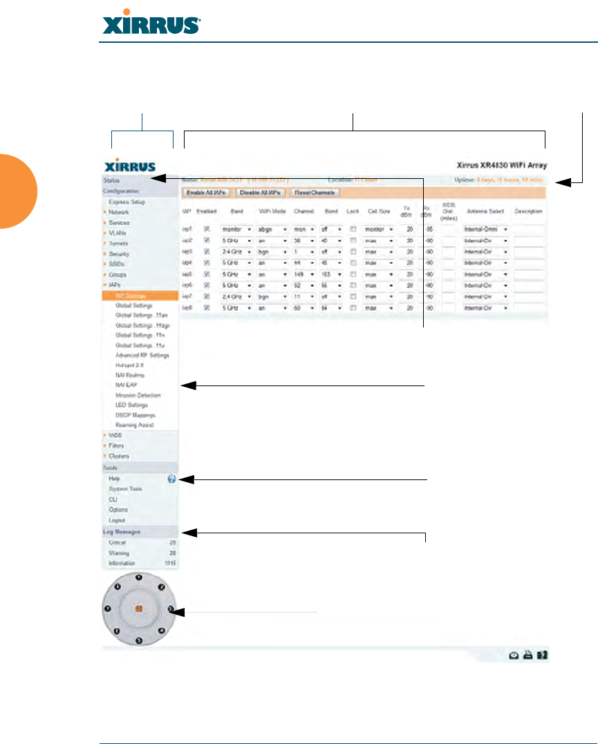
Wireless Array
88 The Web Management Interface
User Interface
Figure 42. WMI: Frames
Left frame Right frame Array info
Click to configure IAP/view statistics
Log Message counters
Top level menu
Help
Pull-down menu
(expand/collapse)
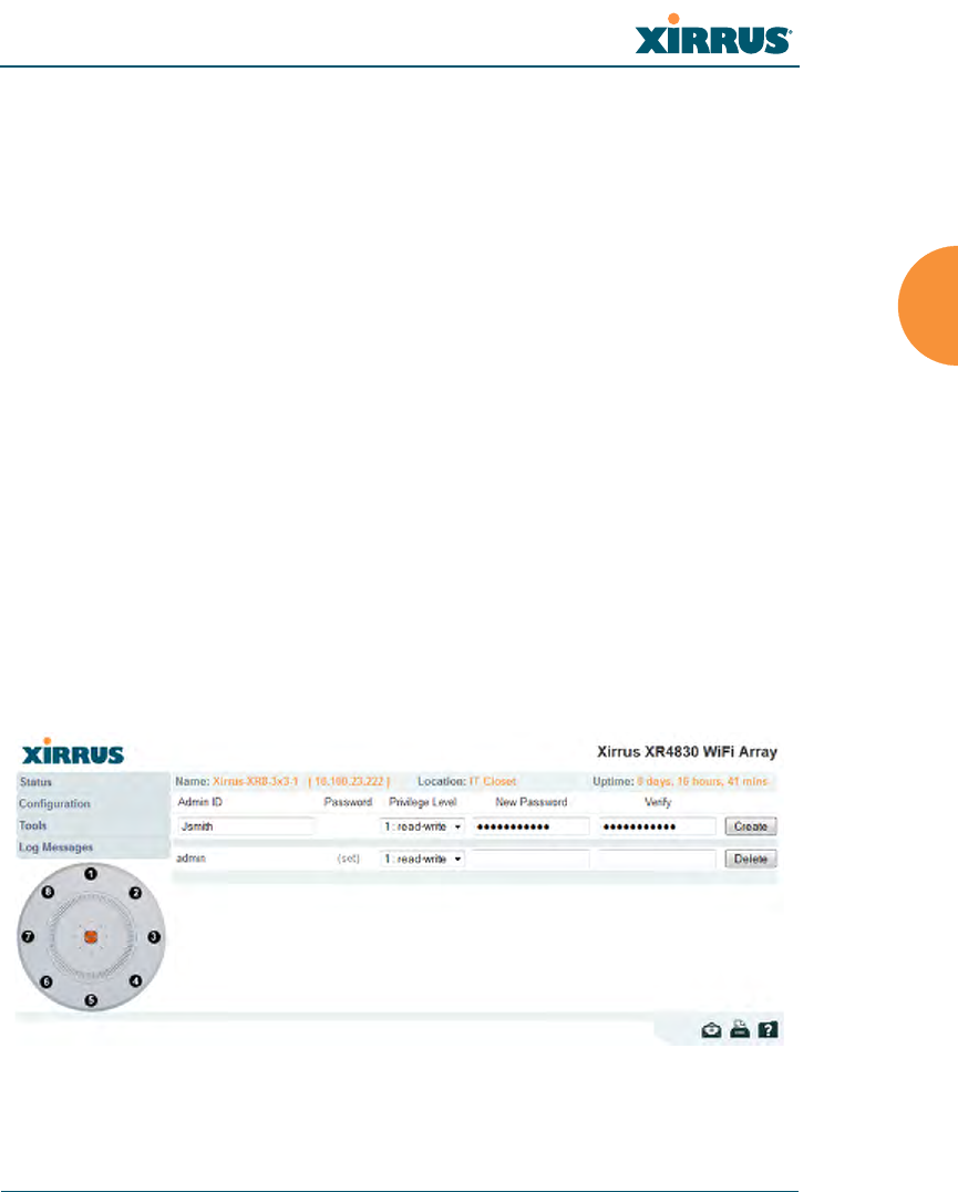
Wireless Array
The Web Management Interface 89
The WMI has been designed with simplicity in mind, making navigation quick
and easy. In the following example, you’ll see that windows are divided into left
and right frames.
The left frame contains three main elements:
Menu organized by function (for example, Network, SSIDs, Security, etc.).
Click a heading, such as Network, to display a summary of its current
configuration, as well as an associated pull-down menu. The three major
menu sections (Status, Configuration, Too ls) may each be collapsed
down to hide the headings under them. Click again to display the
headings. (Figure 43 )
Three Log Messages counters are located at the bottom of the menu. They
provide a running total of messages generated by the ArrayOS Syslog
subsystem during your session — organized into Critical, Warning, and
General messages. Click on a counter to display the associated Syslog
messages. Messages at the selected level or higher will be shown. For
more information, please see “System Log Window” on page 156.
The Array representation contains shortcut links. Click a radio to view
statistics for it. Click the center of the Array to display the IAP Settings
window, which allows you to configure the Array’s radios.
Figure 43. Major Menu Sections Collapsed (on left)

Wireless Array
90 The Web Management Interface
The right frame displays the status information or configuration parameters for
the Wireless Array. This is where you review the Array’s current status and
activity or input data (if you want to make changes). The green Array information
bar at the top of the frame describes the Array — the Name and IP address allow
you to quickly confirm that WMI is connected to the correct Array. The current
Uptime since the last reboot is also shown.
Note that WMI provides options which allow you to change its appearance and
behavior. You may change:
Style — changes the colors and appearance of WMI (i.e., its “skin”).
Refresh Interval — the refresh time when automatic refresh is selected.
Close menu section when deselected — changes the behavior of the
menu in the left frame.
Clear screen when loading new page.
See “Options” on page 373 for more information.
Some settings are only available if the Array’s license includes appropriate
Xirrus Advanced Feature Sets. If a setting is unavailable (grayed out),
then your license does not support the feature. See “About Licensing and
Upgrades” on page 361.
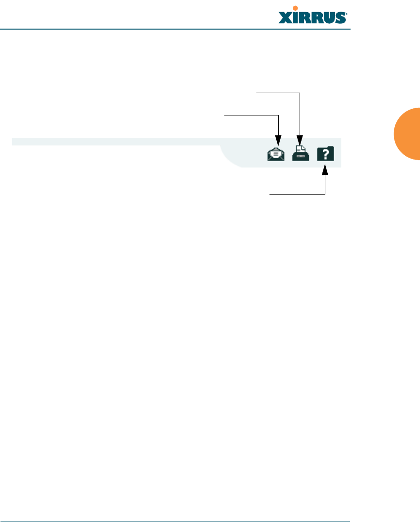
Wireless Array
The Web Management Interface 91
Utility Buttons
At the bottom of each window you will find a set of useful buttons — a Feedback
button, a Print button and a Help button.
Figure 44. WMI: Utility Buttons
Click on the Feedback button to generate a Web page that allows you to
submit your comments to Xirrus, Inc.
Click on the Print button to send a print file of the active window to your
local printer.
Click on the Help button to access the Array’s online help system.
Submitting Your Comments
When submitting comments via the Feedback button (ensure that you provide as
much detail as possible, including your contact information, the product model
number that the comment relates to, and the ArrayOS software version (if
known). When finished, click on the Submit button to submit your comment.
Print button
Help button
Feedback button
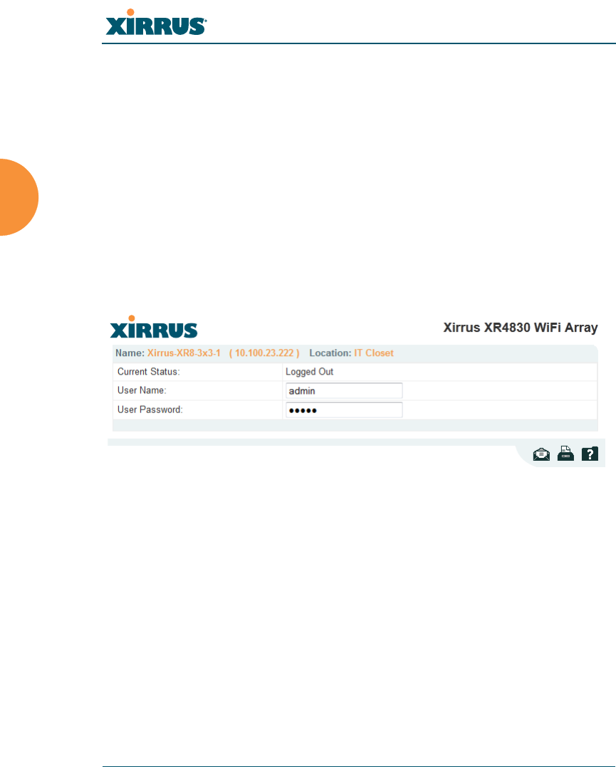
Wireless Array
92 The Web Management Interface
Logging In
Use this procedure to log in to the WMI via your Web browser.
1. Establish a network connection and open your Web browser.
2. If your network supports DHCP and DNS, enter the Array’s default host
name in the browser’s URL. The default host name is simply the Array’s
serial number (for example, XN0823091CACD).
Otherwise, enter the Array’s IP address. This may be determined as
described in “Using the Ethernet Ports” on page 67.
3. To log in to the Array’s Web Management Interface, enter admin for both
the user name and password.
Figure 45. Logging In to the Wireless Array
Applying Configuration Changes
In most of the WMI configuration windows, your changes to settings are applied
to the Array as you make them. In most cases, there is no separate Apply button
to click to make the changes take effect. There are a few exceptions to this rule. In
these cases, a particular section of a page may have its own Apply Settings
button right below the settings.
In both cases described above, the changes that you have made are not saved to
the latest configuration file in the Array’s flash memory, so they will not be
restored after a reboot. Click the Save changes to flash button (located on the
upper right of each page) in order to make sure that these changes will be applied

Wireless Array
The Web Management Interface 93
after rebooting. This will save the entire current configuration, not only the
changes on current WMI page.
Character Restrictions
When inputting strings in the WMI (for example, assigning SSIDs, host name,
password, etc.), use common alphanumeric characters. Some of the fields in the
WMI will not accept special characters, so use of the following characters should
typically be avoided:
&<>' “/ \

Wireless Array
94 The Web Management Interface

Wireless Array
Viewing Status on the Wireless Array 95
Viewing Status on the Wireless
Array
These windows provide status information and statistics for your Array using the
product’s embedded Web Management Interface (WMI). You cannot make
configuration changes to your Array from these windows. The following topics
have been organized into functional areas that reflect the flow and content of the
Status section of the navigation tree in the left frame of the WMI.
“Array Status Windows” on page 96
“Network Status Windows” on page 103
“RF Monitor Windows” on page 114
“Station Status Windows” on page 125
“Statistics Windows” on page 140
“Application Control Windows” on page 150
“System Log Window” on page 156
“IDS Event Log Window” on page 157
Configuration and Tools windows are not discussed here. For information on
these windows, please see:
“Configuring the Wireless Array” on page 159
“Using Tools on the Wireless Array” on page 359
Note that the Status menu section may be collapsed down to hide the headings
under it by clicking it. Click again to display the headings. (See Figure 43 on
page 89)
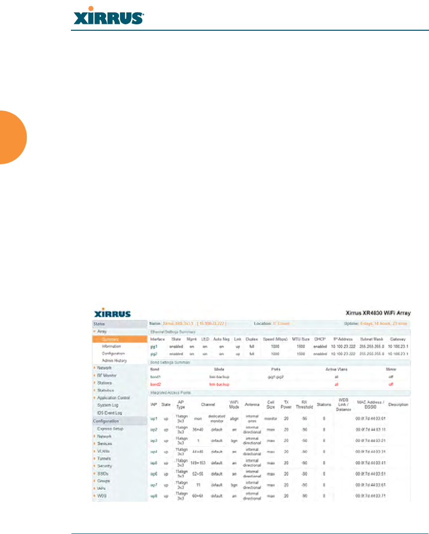
Wireless Array
96 Viewing Status on the Wireless Array
Array Status Windows
The following Array Status windows are available:
Array Summary — displays information on the configuration of all Array
interfaces, including IAPs.
Array Information — provides version/serial number information for all
Array components.
Array Configuration — shows all configuration information for the Array
in text format.
Admin History — shows all current and past logins since the last reboot.
Array Summary
This is a status only window that provides a snapshot of the global configuration
settings for all Wireless Array network interfaces and IAPs. You must go to the
appropriate configuration window to make changes to any of the settings
displayed here — configuration changes cannot be made from this window.
Clicking on an interface or IAP will take you to the proper window for making
configuration changes.
Figure 46. Array Summary

Wireless Array
Viewing Status on the Wireless Array 97
Content of the Array Summary Window
The Array Summary window is sub-divided into the Ethernet Interfaces section
and the Integrated Access Points (radio) section, providing you with the
following information:
Ethernet Settings Summary
This section provides information about network interface devices. To
make configuration changes to these devices, go to “Network Interfaces”
on page 171.
•Interface: Lists the network interfaces that are available on the Array.
•State: Shows the current state of each interface, either enabled or
disabled.
•Mgmt: Shows whether Array management traffic is allowed on this
interface.
•Auto Neg: Shows whether auto-negotiation is in use on this interface,
to determine settings for speed, parity bits, etc.
•LED: Shows whether LED display of interface status is enabled.
•Link: Shows whether the link on this interface is up or down.
•Duplex: Shows whether full duplex mode is in use.
•Speed: Shows the speed of this interface in Mbps.
•MTU Size: Shows the Maximum Transmission Unit size that has
been configured. This is the largest packet size (in bytes) that the
interface can pass along.
•DHCP: Shows whether DHCP on this port is enabled or disabled.
•IP Address: Shows the current IP address assigned to each network
interface device.
•Subnet Mask: Shows the subnet mask, which defines the number of
IP addresses that are available on the routed subnet where the Array
is located.
•Gateway: Shows the IP address of the router that the Array uses to
transmit data to other networks.

Wireless Array
98 Viewing Status on the Wireless Array
Bond Settings Summary
This section provides information about the relationship that has been
selected for the Gigabit ports. For detailed explanations and to make
configuration changes, see “Network Bonds” on page 175.
•Bond: Lists all network bonds that have been configured.
•Mode: Shows the type of relationship that has been selected for the
Gigabit ports.
•Ports: Shows the Gigabit ports that are part of this bond.
•Port Mode: Shows the relationship that has been selected for the
Ethernet ports. See “Network Bonds” on page 175 for details
•Active VLANs: Shows the VLANs that are active in this bond.
•Mirror: Shows whether mirroring is enabled on this bond.
Integrated Access Points Section
This section provides information about the Integrated Access Points
(IAPs) that are contained within the Array. How many IAPs are listed
depends on which product model you are using. To make configuration
changes to these IAPs, go to “IAP Settings” on page 274.
•IAP: Lists the IAPs that are available on the Array.
•State: Shows the current state of each IAP, either up or down. IAPs
that are down are shown in RED. Figure 47 shows an example where
iap7 is down.
•AP Type: Shows the types of 802.11 clients supported by this IAP (11/
a/b/g/n) and the number of separate data streams transmitted and
received by the antennas of each IAP for 802.11n. For example, 3x3
means that the IAP supports three transmit chains and three receive
chains. See “Multiple Data Streams — Spatial Multiplexing” on
page 38.
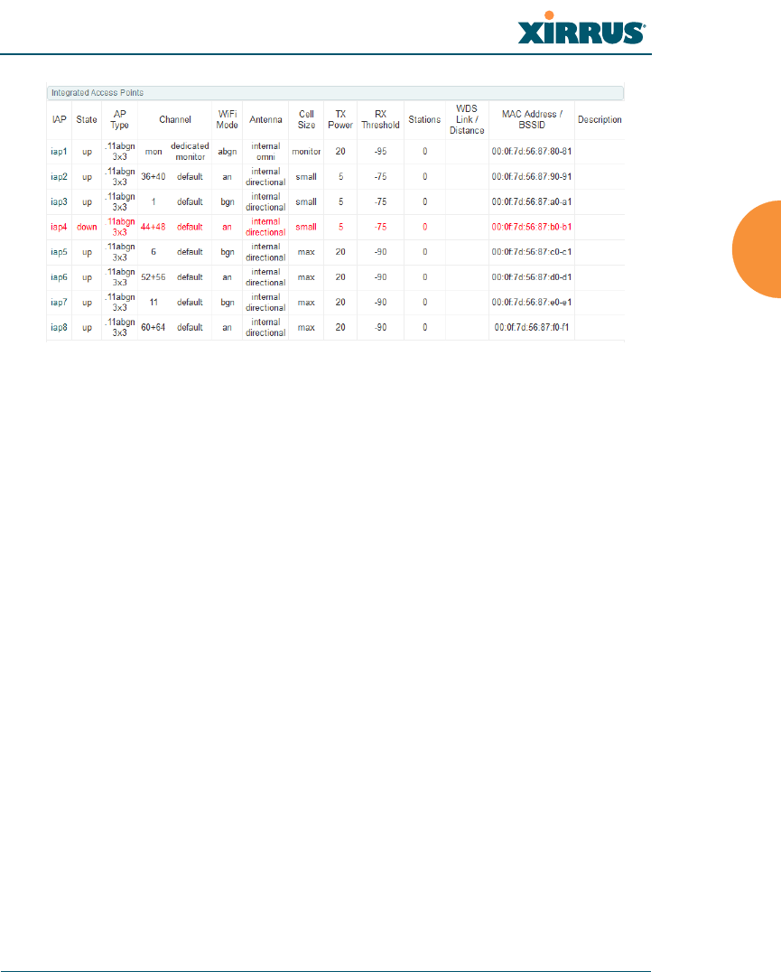
Wireless Array
Viewing Status on the Wireless Array 99
Figure 47. Disabled IAP (Partial View)
•Channel: Shows which channel each IAP is using, and the channel
setting. To avoid co-channel interference, adjacent radios should not
be using adjacent channels. To make channel selections for a specific
IAP, go to “IAP Settings” on page 274.
•Wi-Fi Mode: Shows the 802.11 client types that the IAP has been
configured to support.
•Antenna: Shows which antenna is being used by each IAP.
•Cell Size: Indicates which cell size setting is currently active for each
IAP — small, medium, large, max, automatic, or manually defined by
you. The cell size of an IAP is a function of its transmit power and
determines the IAP’s overall coverage. To define cell sizes, go to “IAP
Settings” on page 274. For additional information about cell sizes and
the importance of planning for and defining the optimum cell sizes
for your Array, go to “Coverage and Capacity Planning” on page 28.

Wireless Array
100 Viewing Status on the Wireless Array
Figure 48. IAP Cells
•Tx Power: Shows the transmit power for each IAP.
•Rx Threshold: Shows the receive threshold for each IAP.
•Stations: Informs you how many client stations are currently
associated with each IAP.
•WDS Link/Distance: The WDS Link on this radio (if any), and
whether the link has been set to support Long Distance Links. See
“WDS” on page 338.
•MAC Address/BSSID: Shows the MAC address for each IAP.
•Description: The description (if any) that you set for this IAP.
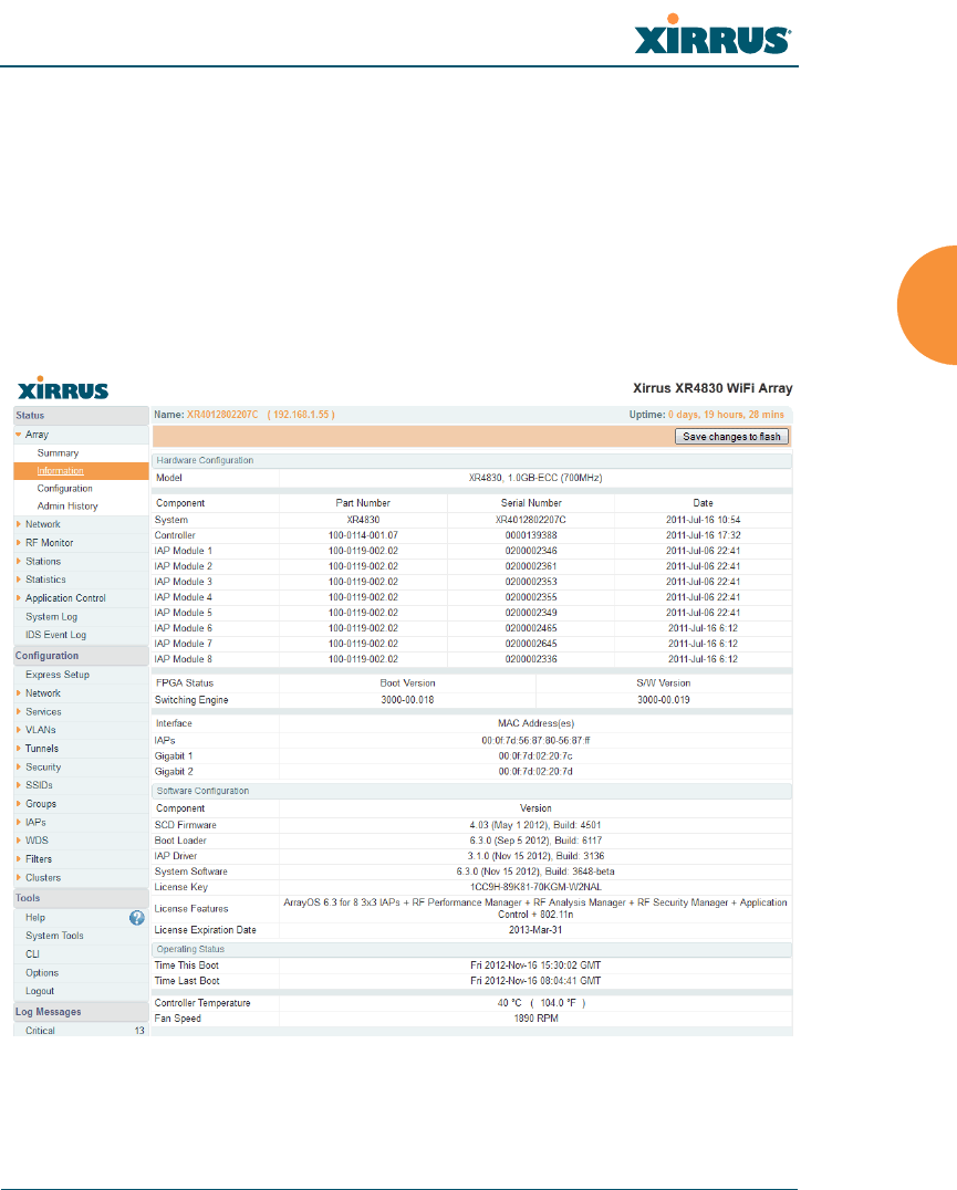
Wireless Array
Viewing Status on the Wireless Array 101
Array Information
This is a status only window that shows you the current firmware versions
utilized by the Array, serial numbers assigned to each module, MAC addresses,
licensing information, recent boot timestamps, and current internal temperatures
and fan speed.
Note that the License Features row lists the features that are supported by your
Array’s license. See “About Licensing and Upgrades” on page 361 and
“Advanced Feature Sets” on page 16 for more information.
Figure 49. Array Information
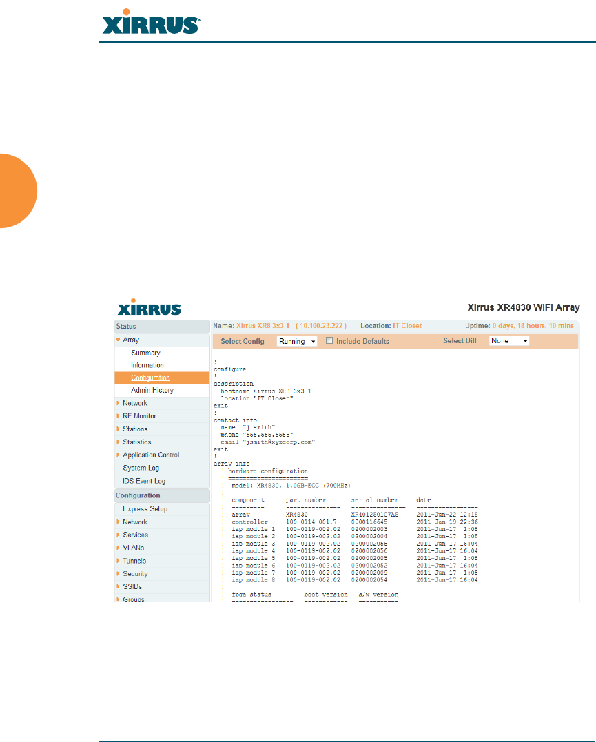
Wireless Array
102 Viewing Status on the Wireless Array
You cannot make configuration changes in this window, but if you are
experiencing issues with network services, you may want to print the content of
this window for your records.
Array Configuration
This is a status only window that allows you to display the configuration settings
assigned to the Array, based on the following filter options:
Running — displays the current configuration (the one running now).
Saved — displays the saved configuration from this session.
Lastboot — displays the configuration as it was after the last reboot.
Factory — displays the configuration established at the factory.
Figure 50. Show Configuration
If you want to see just the differences between the Running, Saved, Lastboot, and
Factory configurations, you can do this by choosing a configuration option from
the Select Config pull-down menu then selecting an alternative configuration
option from the Select Diff pull-down menu.
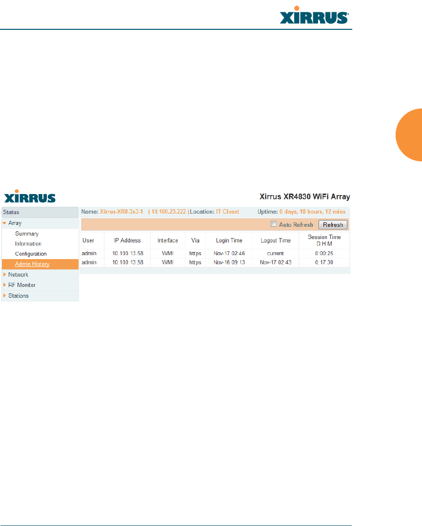
Wireless Array
Viewing Status on the Wireless Array 103
To also include the default configuration settings in the output, choose your
configuration then click in the Include Defaults check box. If Include Defaults is
disabled, then only the changes from the default configuration are shown.
Admin History
It is useful to know who else is currently logged in to an array while you're
configuring it. It's also nice to see who has logged in since the array booted. This
status-only window shows you all administrator logins to the Array that have
occurred since the last reboot. To determine who is currently logged in, check
which entries say active in the Logout Time column.
Figure 51. Admin Login History
Network Status Windows
The following Network Status windows are available:
Network — displays a summary of network interface settings.
Network Map — displays information about this Array and neighboring
Arrays that have been detected.
Spanning Tree Status — displays the spanning tree status of network
links on this Array.
Routing Table — displays information about routing on this Array.
ARP Table — displays information about Address Resolution Protocol on
this Array.
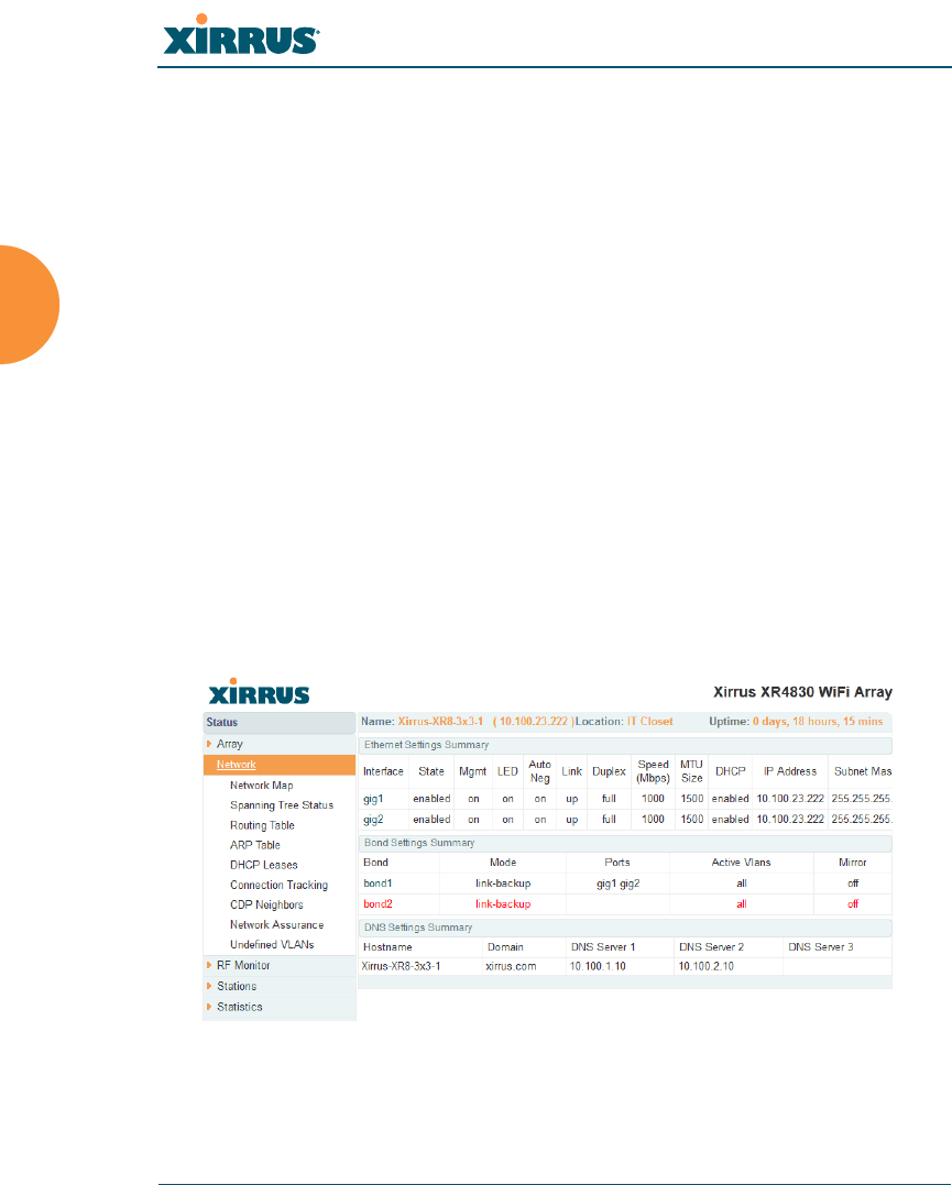
Wireless Array
104 Viewing Status on the Wireless Array
DHCP Leases — displays information about IP addresses (leases) that the
Array has allocated to client stations.
Connection Tracking/NAT — lists connections that have been established
for client stations.
CDP Neighbors — lists neighboring network devices using Cisco
Discovery Protocol.
Network Assurance — shows results of connectivity tests for network
servers.
Undefined VLANs — shows VLANs present on an 802.1Q connection to
the Array, that are not configured in the Array's VLAN list.
Network
This window provides a snapshot of the configuration settings currently
established for Array’s wired interfaces. This includes the Gigabit interfaces and
their bonding settings. DNS Settings are summarized as well. You can click on
any item in the Interface or Bond columns to go to the associated configuration
window.
Figure 52. Network Settings
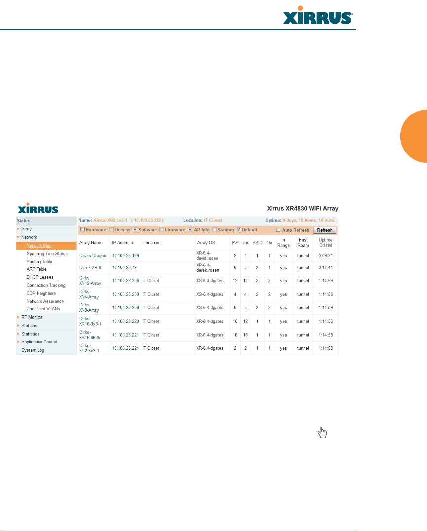
Wireless Array
Viewing Status on the Wireless Array 105
WMI windows that allow you to change or view configuration settings associated
with the network interfaces include:
“Network Interfaces” on page 171
“Network Bonds” on page 175
“DNS Settings” on page 181
“CDP Settings” on page 183
Network Map
This window offers detailed information about this Array and all neighboring
Arrays, including how the Arrays have been set up within your network.
Figure 53. Network Map
The Network Map has a number of options at the top of the page that allow you
to customize your output by selecting from a variety of information that may be
displayed. You may sort the rows based on any column that has an active column
header, indicated when the mouse pointer changes to the hand icon . Click
Refresh to update the information at any time. Click Auto Refresh to instruct the
Array to refresh this window automatically.

Wireless Array
106 Viewing Status on the Wireless Array
Content of the Network Map Window
By default, the network map shows the following status information for each
Array:
Array Name: The host name assigned to the Array. To establish the host
name, go to “Express Setup” on page 161. You may click the host name to
access WMI for this Array.
IP Address: The Array’s IP address. You may click the address to access
WMI for this Array. If DHCP is enabled, the Array’s IP address is
assigned by the DHCP server. If DHCP is disabled, you must assign a
static IP address. To enable DHCP or to assign a static IP address for the
Array, go to “Express Setup” on page 161.
Location: The location assigned to the Array. To establish the location
information, go to “Express Setup” on page 161.
Array OS: The software version running on the Array.
IAP: The number of IAPs on the Array.
(IAP) Up: Informs you how many IAPs are currently up and running. To
enable or disable all IAPs, go to “Express Setup” on page 161. To enable
or disable individual IAPs, go to “IAP Settings” on page 274.
SSID: Informs you how many SSIDs have been assigned for the Array. To
assign an SSID, go to “SSID Management” on page 249.
(SSID) On: Informs you how many SSIDs are enabled. To enable or
disable SSIDs, go to “SSID Management” on page 249.
In Range: Informs you whether the Array is within wireless range of
another Wireless Array.
Fast Roam: Informs you whether or not the Xirrus fast roaming feature is
enabled. This feature utilizes the Xirrus Roaming Protocol (XRP) ensuring
fast and seamless roaming capabilities between IAPs or Arrays at both
Layer 2 and Layer 3. To enable or disable fast roaming, go to “Global
Settings (IAP)” on page 280.
Uptime (D:H:M): Informs you how long the Array has been up and
running (in Days, Hours and Minutes).

Wireless Array
Viewing Status on the Wireless Array 107
To see additional information, select from the following checkboxes at the bottom
of the page. This will show the columns described below.
Hardware
Model: The model number of each Array (XR-4820, XR-7630, etc.), plus
the amount of RAM memory and the speed of the processor.
Serial: Displays the serial number of each Array.
License
License: The license key of each Array.
Licensed Features: Lists the optional features enabled by the key, if any.
Software (enabled by default)
Enable/disable display of the Array OS column.
Firmware
Boot Loader: The software version number of the boot loader on each
Array.
SCD Firmware: The software version number of the SCD firmware on
each Array.
IAP Info (enabled by default)
Enable/disable display of the IAP/Up columns.
Stations
Stations: Tells you how many stations are currently associated to each
Array. To deauthenticate a station, go to “Stations” on page 126.
The columns to the right (H, D, W, and M) show the highest number of
stations that have been associated over various periods of time: the
previous hour, day, week, and month.
Default
Sets the columns displayed to the default settings. By default, only
Software and IAP Info are selected.
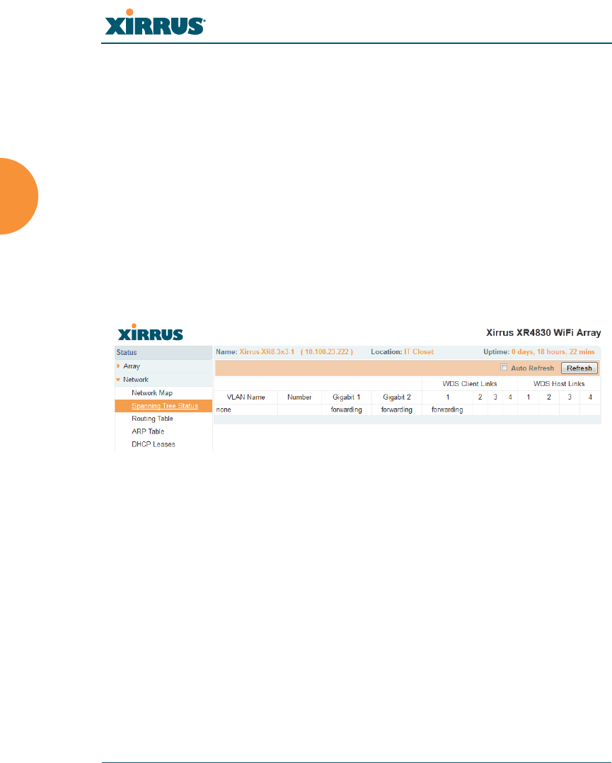
Wireless Array
108 Viewing Status on the Wireless Array
Spanning Tree Status
Multiple active paths between stations can cause loops in the network. If a loop
exists in the network topology, the potential exists for the duplication of
messages. The spanning tree protocol is a link management protocol that
provides path redundancy while preventing undesirable loops. For a wireless
network to function properly, only one active path can exist between two stations.
To facilitate path redundancy, the spanning tree protocol defines a tree that spans
all stations in the network and forces certain redundant data paths into a standby
(blocked) state. If one segment in the spanning tree becomes unreachable, the
spanning tree algorithm reconfigures the network topology and reestablishes the
link by activating the standby path. The spanning tree function is transparent to
client stations.
Figure 54. Spanning Tree Status
This window shows the spanning tree status (forwarding or blocked) for path
segments that terminate on the gigabit ports and WDS links of this Array. You
may sort the rows based on the VLAN Name or Number columns by clicking the
column header. Click Refresh to update the information at any time. Click Auto
Refresh to instruct the Array to refresh this window automatically.
See Also
Network
Network Interfaces
Network Status Windows
VLANs
WDS
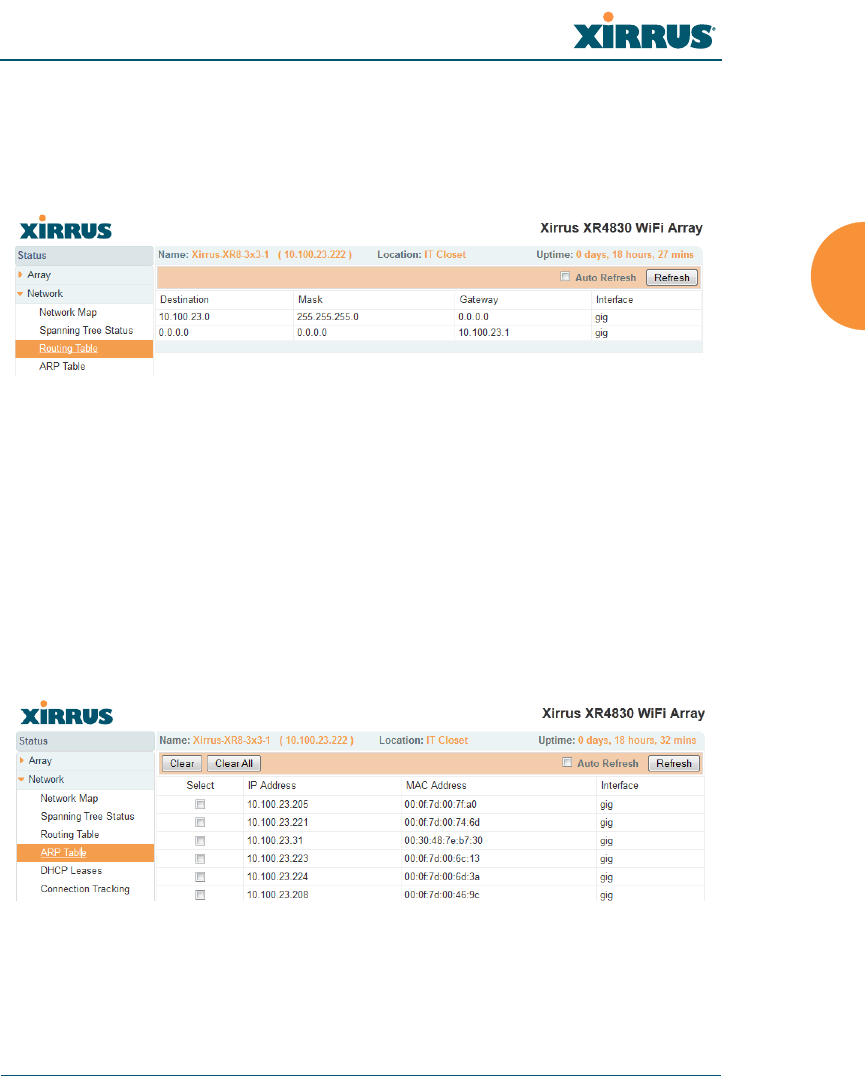
Wireless Array
Viewing Status on the Wireless Array 109
Routing Table
This status-only window lists the entries in the Array’s routing table. The table
provides the Array with instructions for sending each packet to its next hop on its
route across the network.
Figure 55. Routing Table
See Also
VLANs
Configuring VLANs on an Open SSID
ARP Table
This status-only window lists the entries in the Array’s ARP table. For a device
with a given IP address, this table lists the device’s MAC address. It also shows
the Array interface through which this device may be reached. The table typically
includes devices that are on the same local area network segment as the Array.
Figure 56. ARP Table
See Also
Routing Table
ARP Filtering
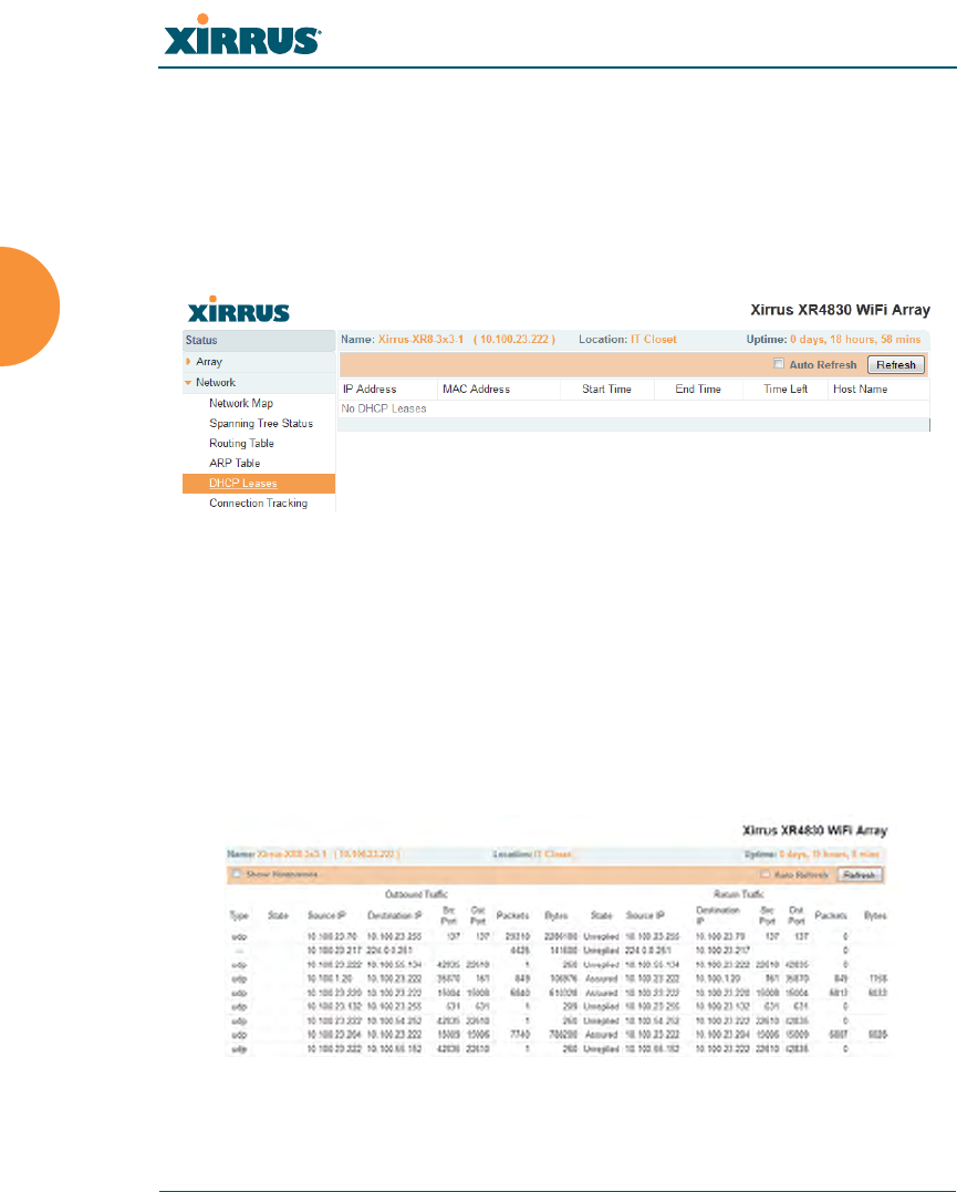
Wireless Array
110 Viewing Status on the Wireless Array
DHCP Leases
This status-only window lists the IP addresses (leases) that the Array has
allocated to client stations. For each, it shows the IP address assigned from one of
the defined DHCP pools, and the MAC address and host name of the client
station. The start and end time of the lease show how long the allocation is valid.
The same IP address is normally renewed at the expiration of the current lease.
Figure 57. DHCP Leases
See Also
DHCP Server
Connection Tracking/NAT
This status-only window lists the session connections that have been created on
behalf of clients. This table may also be used to view information about current
NAT sessions.
Figure 58. Connection Tracking
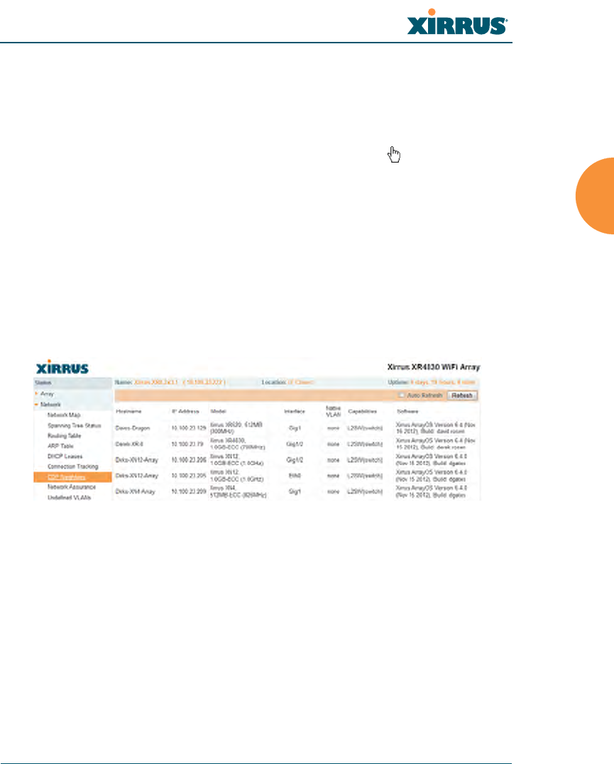
Wireless Array
Viewing Status on the Wireless Array 111
Click the Show Hostnames checkbox at the top of the page to display name
information (if any) for the source and destination location of the connection. The
Hostname columns will replace traffic statistics columns.
You may sort the rows based on any column that has an active column header,
indicated when the mouse pointer changes to the hand icon . Click Refresh to
update the information at any time. Click Auto Refresh to instruct the Array to
refresh this window automatically.
See Also
Filters
CDP Neighbors
This status-only window lists devices on the Array’s network that support the
Cisco Discovery Protocol (CDP).
Figure 59. CDP Neighbors
The Array performs discovery on the network on an ongoing basis. This list
shows the devices that have been discovered — Cisco devices and other devices
on the network that have CDP running. For each, it shows the device’s host name,
IP address, manufacturer and model name, the device interface that is connected
to the network (i.e., the port that was discovered), and the network capabilities of
the device (switch, router, supported protocols, etc.).
CDP must be enabled on the Array in order to gather and display this
information. For details and some restrictions, see “CDP Settings” on page 183.
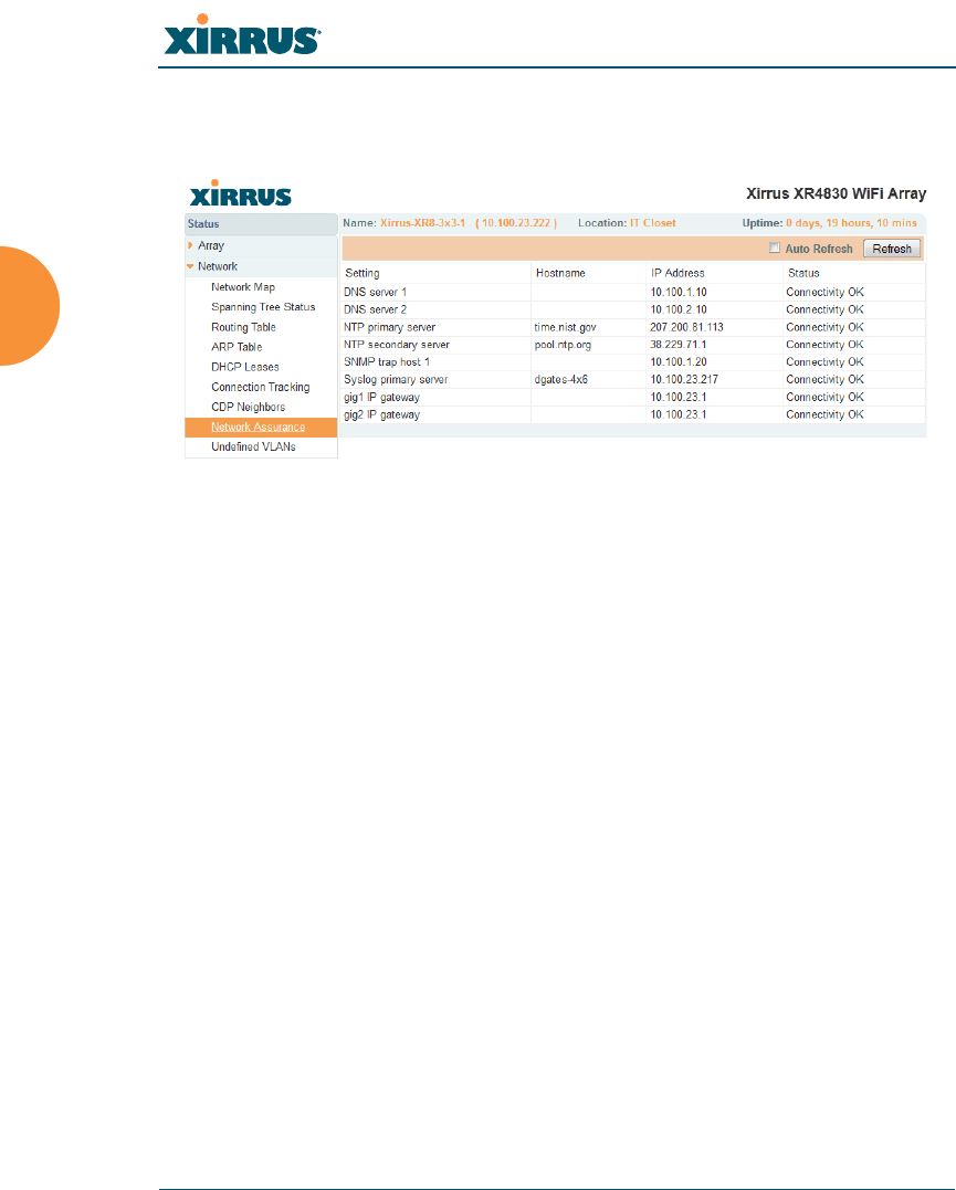
Wireless Array
112 Viewing Status on the Wireless Array
Network Assurance
This status-only window shows the results of ongoing network assurance testing.
Figure 60. Network Assurance
The Array checks connectivity to network servers that you have configured (for
example, DNS and NTP servers) on an ongoing basis. For each server, this list
shows the server’s host name (if any), IP address, and status.
Network assurance must be enabled on the Array in order to perform these
connectivity tests and display this information. See “Management Control” on
page 221.
See Also
Management Control
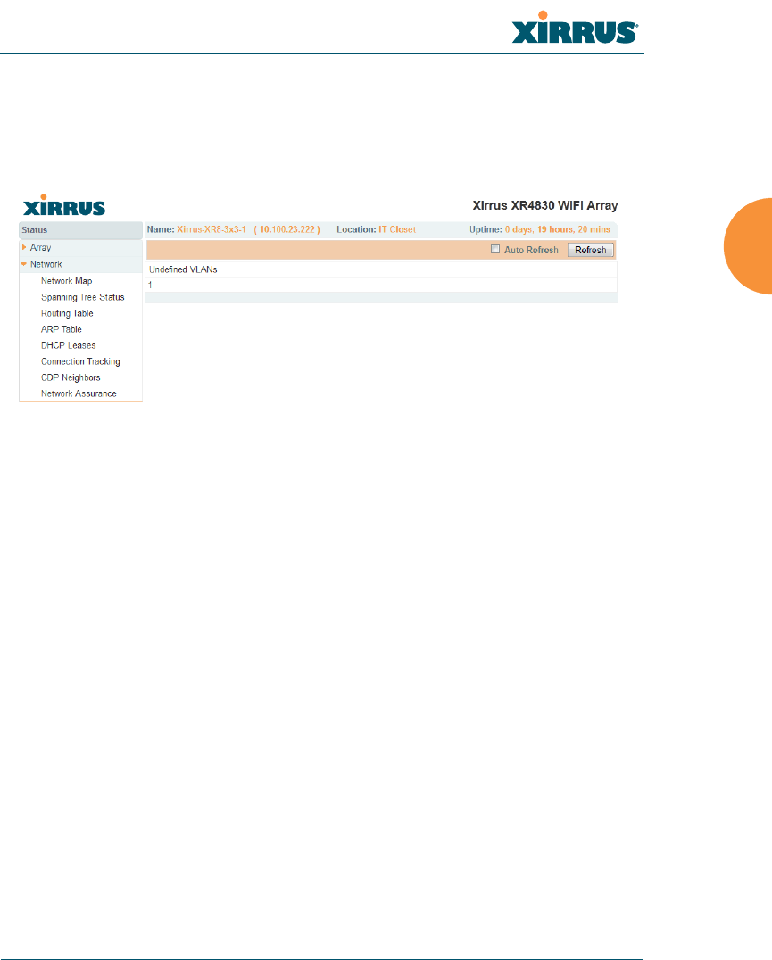
Wireless Array
Viewing Status on the Wireless Array 113
Undefined VLANs
This status-only window lists VLANs that have not been configured on the Array,
but that are being detected on the Array’s trunk port(s), i.e. wired ports. See
“VLANs” on page 199.
Figure 61. Undefined VLANs
This feature alerts you to the fact that an 802.1Q trunk to the Array has VLANs
that are not being properly handled on the Array. To reduce unnecessary traffic,
only VLANs that are actually needed on the Array should normally be on the
trunk, e.g., the management VLAN and SSID VLANs. In some cases such as
multicast forwarding for Apple Bonjour you may want to extend other VLANs to
the Array, in order to forward Bonjour or other multicast packets (see “Advanced
Traffic Optimization” on page 284).
See Also
VLANs

Wireless Array
114 Viewing Status on the Wireless Array
RF Monitor Windows
Every Wireless Array includes an integrated RF spectrum analyzer as a standard
feature. The spectrum analyzer allows you to characterize the RF environment by
monitoring throughput, signal, noise, errors, and interference levels continually
per channel. This capability uses the assigned threat-sensor (monitor) radio. The
associated software is part of the ArrayOS.
The following RF Status windows are available:
IAPs — displays current statistics and RF measurements for each of the
Array’s IAPs.
Spectrum Analyzer — displays current statistics and RF measurements
for each of the Array’s channels.
Intrusion Detection — displays rogue APs that have been detected by the
Array.
Channel History — charts ongoing statistics and RF measurements for
one selected channel over time.
Radio Assurance — displays counts of types of problems that caused each
IAP to reset.
Some status information is only available if the Array’s license includes
Advanced Feature Sets. For example, the Spectrum Analyzer requires the
Xirrus Advanced RF Analysis Manager (RAM). If a feature is
unavailable, then your license does not support the feature and you will get
an error message if you try to set the feature. See “About Licensing and
Upgrades” on page 361.
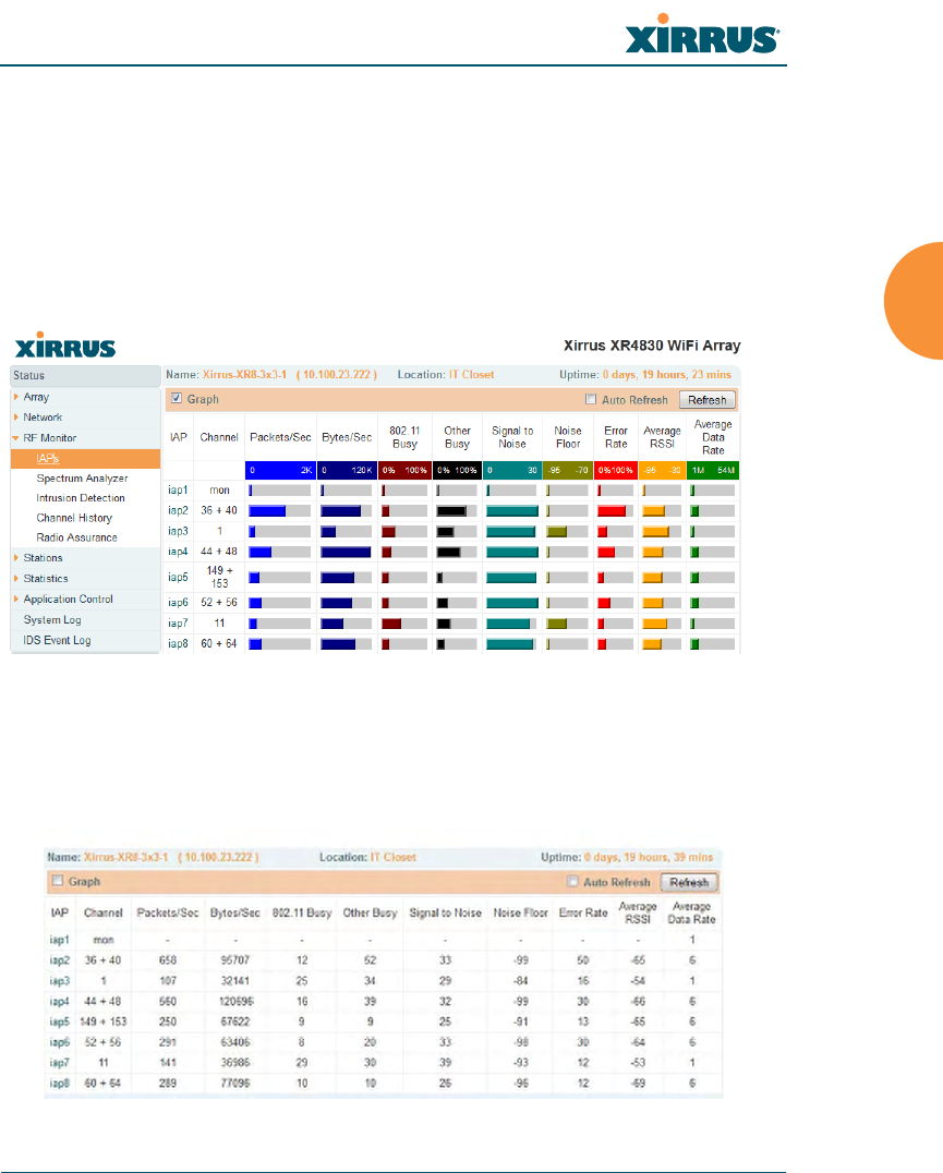
Wireless Array
Viewing Status on the Wireless Array 115
IAPs
The RF Monitor — IAPs window displays traffic statistics and RF readings
observed by each Array IAP (radio). Note that the data is an instantaneous
snapshot for the IAP — it is not an average or a cumulative total. To graph these
values over time for a particular channel, see “Channel History” on page 121. For
detailed information on the measurements displayed, please see “Spectrum
Analyzer Measurements” on page 118.
Figure 62. RF Monitor — IAPs
Figure 62 presents the data as a graphical display, enabled by selecting the Graph
checkbox on the upper left. If this option is not selected, data is presented as a
numerical table.
Figure 63. RF Monitor — IAPs

Wireless Array
116 Viewing Status on the Wireless Array
You may sort the rows based on any column that has an active column header,
indicated when the mouse pointer changes to the hand icon . Click Refresh to
update the information at any time. Click Auto Refresh to instruct the Array to
refresh this window automatically.
Spectrum Analyzer
Spectrum analysis on Wireless Arrays is a distributed capability that
automatically covers the entire wireless network, since a sensor is present in every
unit. Arrays monitor the network 24/7 and analyze interference anywhere in the
network from your desk. There’s no need to walk around with a device as with
traditional spectrum analyzers, thus you don’t have to be in the right place to find
outside sources that may cause network problems or pose a security threat. The
Array monitors all 802.11 radio bands (a/b/g/n), not just those currently used for
data transmission.
The RF Spectrum Analyzer window displays instantaneous traffic statistics and
RF readings for all channels, as measured by the Array’s monitor radio. This
differs from the RF Monitor-IAPs window, which displays values measured by
each IAP radio for its current assigned channel. For the spectrum analyzer, the
monitor radio is in a listen-only mode, scanning across all wireless channels. Each
channel is scanned in sequence, for a 250 millisecond interval per channel. The
spectrum analyzer window presents the data as a graphical display of vertical bar
graphs for each statistic as shown in Figure 64 (the default presentation), or
horizontally as bar graphs or numerical RF measurements. The measurements
displayed are explained in “Spectrum Analyzer Measurements” on page 118.
As an aid to viewing data for a particular channel, click the channel number. The
channel will be highlighted down the page (or across the page for a rotated view,
in both text and graph modes). Click additional channels to highlight them for
easy comparison. To remove the highlighting from a channel, click the channel
number again. Click Refresh to update the information at any time. Click Auto
Refresh to instruct the Array to refresh this window automatically.
The RF measurements for this feature are obtained by the monitor radio. You
must have a radio set to monitor mode for any data to be available. See
“IAP Settings” on page 274.
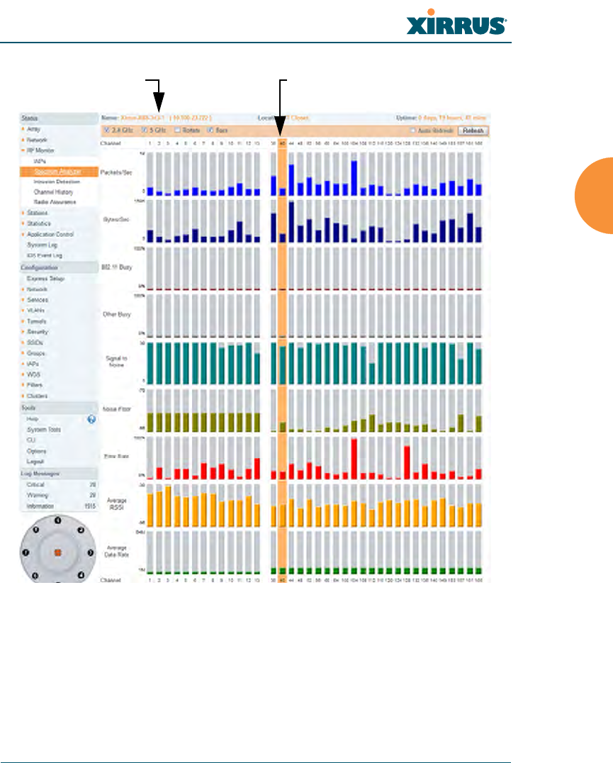
Wireless Array
Viewing Status on the Wireless Array 117
Figure 64. RF Spectrum Analyzer
The Spectrum Analyzer offers several display options:
To display horizontal bar graphs, click the Rotate checkbox at the bottom
of the data window.
In the rotated view, if you wish to view data as a numerical table, click the
Text checkbox. Click again to return to a graphical display. The text
option is only available in the rotated view.
Click Channel number to highlightSelect Display Options

Wireless Array
118 Viewing Status on the Wireless Array
When viewing a graphical display, click Bars to have the bar graphs
displayed against a gray background — you may find this easier on the
eyes. This operation is not available when Text is selected.
You may sort the rows based on any column that has an active column
header, indicated when the mouse pointer changes to the hand icon .
Sorting is only available in the rotated view.
At the bottom left of the frame, you may select whether to display only
2.4 GHz channels, 5 GHz channels, or both (the default is both). Note that
the data is an instantaneous snapshot — it is not an average or a
cumulative total.
Spectrum Analyzer Measurements
The spectrum analyzer displays the following information:
Packets/Sec: Total number of wireless packets per second on the channel,
both valid and errored packets.
Bytes/Sec: Total number of wireless bytes per second on the channel,
valid packets only.
802.11 Busy: Percentage of time that 802.11 activity is seen on the channel.
Other Busy: Percentage of time that the channel is unavailable due to
non-802.11 activity.
The total busy time (802.11 Busy plus Other Busy) will never total more
than 100%. The remaining time (100% minus total busy time) is quiet
time — the time that no activity was seen on the channel.
Signal to Noise: Average SNR (signal to noise ratio) seen on the channel,
calculated from the signal seen on valid 802.11 packets less the noise floor
level. A dash value “-“means no SNR data was available for the interval.
Noise Floor: Average noise floor reading seen on the channel (ambient
noise). A dash value “-“means no noise data was available for the
interval.
Error Rate: Percentage of the total number of wireless packets seen on the
channel that have CRC errors. The Error rate percentage may be high on
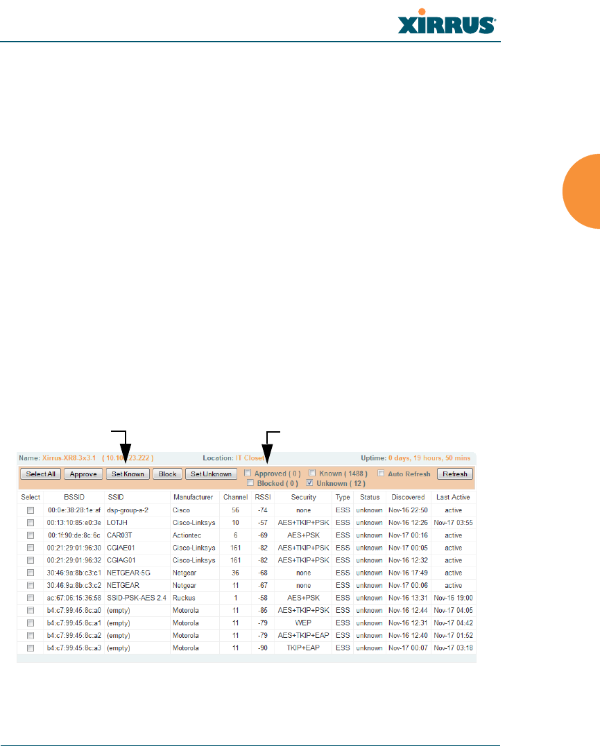
Wireless Array
Viewing Status on the Wireless Array 119
some channels since the monitor radio is set to receive at a very sensitive
level, enabling it to hear packets from devices at far distances.
Average RSSI: Average RSSI level seen on 802.11 packets received on the
channel. A dash value “-“means no RSSI data was available for the
interval.
Average Data Rate: Average data rate over time (per byte, not per packet)
seen on 802.11 packets received on the channel. A dash value “-“means
no data rate information was available for the interval. A higher date rate
(above 6 Mbps) typically indicates user data traffic on the channel.
Otherwise, the data rate reflects control packets at the lower basic rates.
Intrusion Detection
This window displays all detected access points, according to the classifications
you select from the checkboxes at the top — Blocked, Unknown, Known, or
Approved. This includes ad hoc access points (station-to-station connections). For
more information about intrusion detection, rogue APs, and blocking, please see
“About Blocking Rogue APs” on page 331.
Figure 65. Intrusion Detection/Rogue AP List
Select APs to DisplayClassify APs

Wireless Array
120 Viewing Status on the Wireless Array
The Intrusion Detection window provides the easiest method for classifying
rogue APs as Blocked, Known, Approved, or Unknown. Choose one or more APs
using the checkbox in the Select column, then use the buttons on the upper left to
classify them with the following actions: Approve, Set Known, Block, or Set
Unknown.
You can sort the results based on the following parameters by clicking the desired
column header:
You can refresh the list at any time by clicking on the Refresh button, or click in
the Auto Refresh check box to instruct the Array to refresh the list automatically.
See Also
Network Map
Rogue Control List
SSIDs
SSID Management
SSID Security
BSSID Type
Manufacturer Status
Channel Discovered
RSSI Last Active
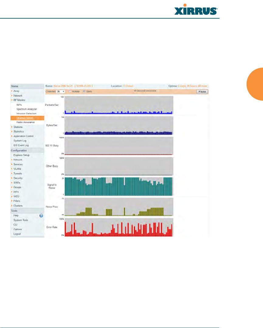
Wireless Array
Viewing Status on the Wireless Array 121
Channel History
The RF Monitor — Channel History window focuses on traffic statistics and RF
readings observed for just one channel that you select in the Channel field. A new
set of readings is added every 10 seconds for a 5 GHz channel, or every 5 seconds
for a 2.4 GHz channel. For descriptions of the measurements displayed, please see
“Spectrum Analyzer Measurements” on page 118.
Figure 66. RF Monitor — Channel History
Figure 66 presents the data in graphical form. New data appears at the left, with
older readings shifting to the right. To make the data appear as a barchart, click
the Bar checkbox which will shade the background.
You also have the option of clicking the Rotate checkbox to give each statistic its
own column. In other words, the graph for each statistic will grow down the page
as new readings display at the top. (Figure 67)
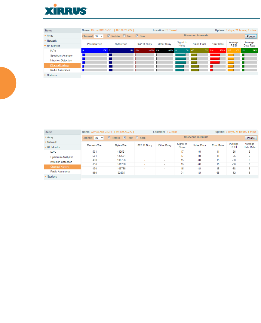
Wireless Array
122 Viewing Status on the Wireless Array
Figure 67. RF Monitor — Channel History (Rotated)
If you select Rotate and Tex t together, data is presented as a numerical table.
(Figure 68)
Click Pause to stop collecting data, or Resume to continue.
Figure 68. RF Monitor — Channel History (Text)
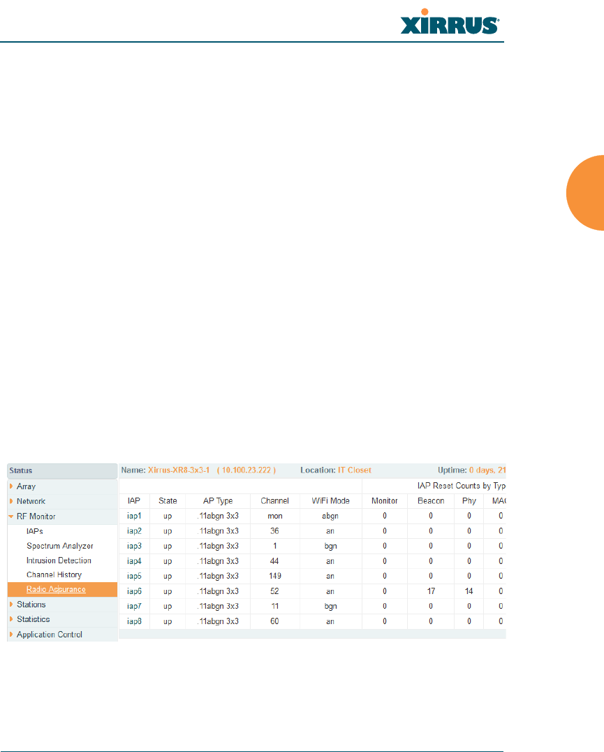
Wireless Array
Viewing Status on the Wireless Array 123
Radio Assurance
When Radio Assurance mode is enabled, the monitor radio performs loopback
tests on the Array’s radios. When problems are encountered, the Array can take
various actions to correct them by performing different levels of reset on the
affected radio. This window shows which resets, if any, have been performed on
which radios since the last reboot.
The Array’s response to radio problems is controlled by the Radio Assurance
Mode selected, as described in “RF Resilience” on page 315. If you have selected
Failure Alerts & Repairs (with or without reboots), then the Array can take
corrective action if a problem is detected. Note that radio assurance requires RF
Monitor Mode to be enabled in Advanced RF Settings to turn on self-monitoring
functions. It also requires a radio to be set to monitoring mode. For a detailed
discussion of the operation of this feature and the types of resets performed, see
“Radio Assurance” on page 461.
Figure 69. Radio Assurance
For each of the Array’s radios, this window shows the radio’s state, its type (IEEE
802.11 type, and antenna type—2x2 or 3x3), the assigned channel, and the selected
802.11 wireless mode. To the right, the table shows counts for the number of
Radio Assurance mode is only available if the Array’s license includes the
Xirrus Advanced RF Analysis Manager (RAM). If a setting is
unavailable (grayed out), then your license does not support the feature.
Please see “About Licensing and Upgrades” on page 361.

Wireless Array
124 Viewing Status on the Wireless Array
times, if any, that radio assurance has performed each of the following types of
resets since the last reboot, as described in Radio Assurance:
Monitor
Beacon
Phy
MAC
System (i.e., reboot the Array)
See Also
IAPs
Xirrus Advanced RF Analysis Manager (RAM)
RF Resilience
Radio Assurance

Wireless Array
Viewing Status on the Wireless Array 125
Station Status Windows
The following Station Status windows are available:
Stations — this list describes all stations associated to the Array.
Location Map — displays a map showing the approximate locations of all
stations associated to the array.
RSSI — for each associated station, this displays the Received Signal
Strength Indicator at each of the Array’s IAPs.
Signal-to-Noise Ratio (SNR) — for each associated station, this displays
the SNR at each of the Array’s IAPs.
Noise Floor — for each associated station, this displays the ambient noise
(silence) value at each of the Array’s IAPs.
Max by IAP — for each IAP, this shows the historical maximum number
of stations that have been associated to it over various periods of time.
Station Assurance — displays stations that are having connectivity
problems.
Some status information is only available if the Array’s license includes the
Xirrus Advanced RF Analysis Manager (RAM). If a feature is
unavailable, then your license does not support the feature and you will get
an error message if you try to set the feature. See “About Licensing and
Upgrades” on page 361.
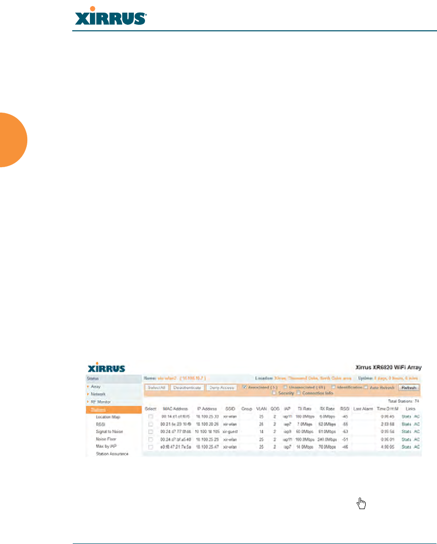
Wireless Array
126 Viewing Status on the Wireless Array
Stations
This status-only window shows client stations currently visible to the Array. You
may choose to view only stations that have Associated to the Array, or only
stations that are Unassociated, or both, by selecting the appropriate checkboxes
above the list. The list always shows the MAC address of each station, its IP
address, the SSID used for the association, the Group (if any) that this station
belongs to, its VLAN, its QoS, the IAP used for the association, transmit and
receive rates, the RSSI for each station, and how long each association has been
active (up time).
You may click other checkboxes above the list to show a number of additional
columns:
Identification: shows more identifying information for the station — its
User Name, Host Name, Manufacturer, Device Type, and Device Class
(for example, notebook, iPad, etc.).
Security: includes security settings used by the connection —
Enc(ryption) type, Cipher used, Key Mgmt used, and Media supported
by the station.
Connection Info: shows the Band (5GHz or 2.4 GHz) and Channel(s)
used (plus bonded channel, if any, for 802.11n). Shows additional RF
measurements that affect the quality of the connection: SNR (signal to
noise ratio) and Silence — the ambient noise (floor) value.
Figure 70. Stations
You may sort the rows based on any column that has an active column header,
indicated when the mouse pointer changes to the hand icon . Click again to

Wireless Array
Viewing Status on the Wireless Array 127
reverse the sort order. You may select a specific station and perform one of the
following actions by clicking the associated button:
Deny Access: Sends a de-authentication frame to the selected station and
explicitly denies it access by adding its MAC address to the Deny List in
the Access Control List window. To permit access again, go to “Access
Control List” on page 227 and delete the station from the Deny list.
Deauthenticate: Sends a de-authentication frame to the selected station.
The station may re-authenticate.
Click on the Refresh button to refresh the station list, or click in the Auto Refresh
check box to instruct the Array to refresh this window automatically.
See Also
Access Control List
Station Status Windows
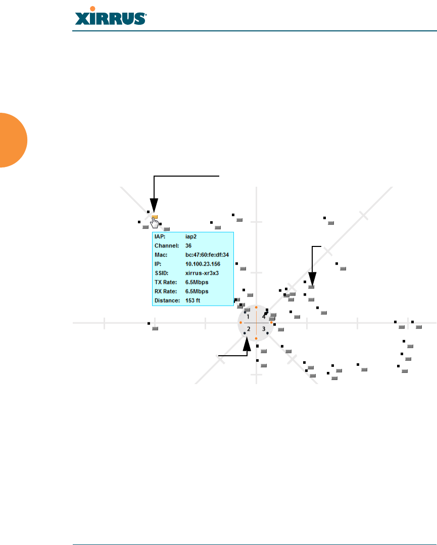
Wireless Array
128 Viewing Status on the Wireless Array
Location Map
The Location Map shows the approximate locations of stations relative to this
Array. The location of each station is computed based on the RSSI of its signal as
received by the Array. The distance is adjusted based on the environment setting
that you selected. You may display just the stations associated to this Array,
unassociated stations (shown in gray), or both. The station count is shown on the
right, above the map. You may also choose to display only 5 GHz stations (shown
in orange) or 2.4 GHz stations (shown in green), or both.
Figure 71. Location Map
The map and Array are shown as if you were looking down on the Array from
above, say from a skylight on the roof. Thus the positions of the radios are a
mirror image of the way they are typically drawn when looking at the face of the
Array. Radios are marked on the map to show the orientation of the Array.
A station is identified by the type of Preferred Label that you select: Netbios
Name, IP Address, MAC Address, or Manufacturer. If multiple stations are near
each other, they will be displayed slightly offset so that one station does not
Associated Stations
orange - 5 GHz
green - 2.4GHz
Unassociated Station
Hover mouse to
show details
Array
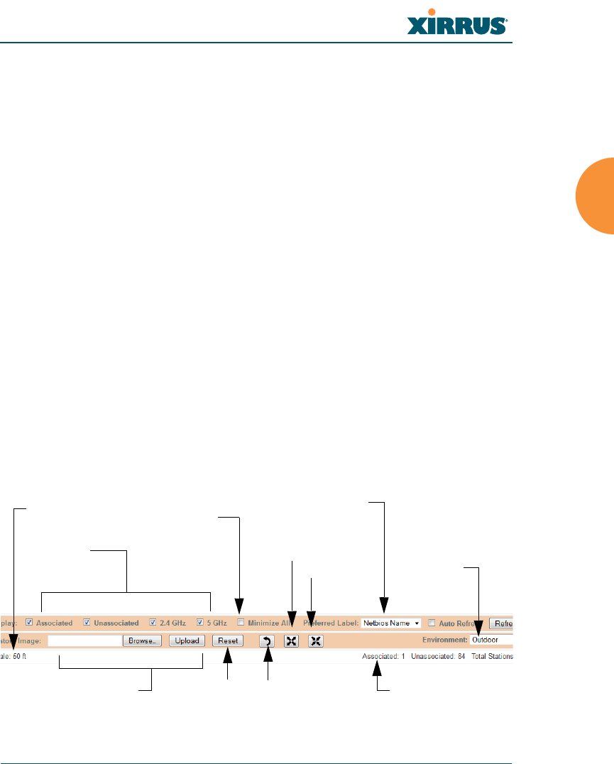
Wireless Array
Viewing Status on the Wireless Array 129
completely obscure another. You may minimize a station that is not of interest by
clicking it. There is also a Minimize All button.
You may replace the range-finder background image above with your own
custom image of the floorplan of the area served by the Array — see “Working
with the Custom Image” on page 131
Hover the mouse over a station to show detailed information. (Figure 71) For a
station that is associated to this Array, the details include:
The IAP, Channel, and SSID to which the station is associated.
The MAC and IP address and Netbios name of the station.
The TX Rate and RX Rate of this connection.
The approximate Distance of this station from the Array. The distance is
estimated using the received signal strength and your environment
setting. The environment determines the typical signal attenuation due to
walls and other construction that affect signal reception.
Controls and items displayed on the Location Map window
Figure 72. Controls for Location Map
The Location Map has its own scroll bars in addition to the browser’s scroll
bars. If you narrow the browser window, the map’s scroll bar may be hidden.
Use the browser’s bottom scroll bar if you need to move it into view.
Stations
to display Environment
Setting
Replace background
Minimize stations
Reset display Rotate map
Zoom in
Zoom out
Scale Preferred
Label
Station counts

Wireless Array
130 Viewing Status on the Wireless Array
Display Associated/Unassociated: Select whether to display stations that
are associated to the Array, stations that are not associated, or both.
Display 2.4 GHz/5 GHz: Select whether to display 802.11bgn stations, or
802.11an stations, or both.
Preferred Label: This field is located on the top of the window towards
the right. It selects the type of label to be displayed for stations: Netbios
Name, IP Address, MAC Address, or Manufacturer. If you select
NetBIOS (this is the default), then that name, if known, will be used to
label each Array. Else, its IP or MAC address will be used, in that order.
Auto Refresh: Instructs the Array to refresh this window automatically.
Refresh: Updates the stations displayed.
Custom Image: Use this feature to replace the default background image
with your own image of the floor plan of your location. Click the Browse
button and browse to the desired file on your computer. This may be a
.gif, .jpg, .jpeg., .png, .htm, or .html file. The scale of the file should be 100
feet per inch. Then click Upload (see below). For more information on
using the custom, image, see “Working with the Custom Image” on
page 131.
Upload: After browsing to the desired custom image, click the Upload
button to install it. The map is redisplayed with your new background.
No hash marks (for the map scale) are added to the image display.
Reset: Click this button to restore the map display to the factory settings.
All attributes are restored — including the stations selected for display, the
scale, the rotation, and the background map.
Rotate: Click this button to rotate the orientation of the entire map. It
rotates the map 45o counter-clockwise.
Enlarge: Click this button to enlarge (zoom in on) the map. The displayed
Scale is updated with the new scale for the map.
Reduce: Click this button to reduce (zoom out on) the map.
The displayed Scale is updated with the new scale for the map.

Wireless Array
Viewing Status on the Wireless Array 131
Environment: This field is located on the top right of the window. Select
the type of environment for this Array’s deployment: Indoor open (few
walls or obstructions), Indoor walled (typical wall or cubicle
construction), or Indoor dense (many walls or obstructions, or unusually
dense walls).
Scale: This view-only value shows the approximate distance represented
by each hashmark on the default map background.
Associated, Unassociated, Total Stations: These view-only values show
the station counts observed by the Array.
See Also
Station Status Windows
Working with the Custom Image
After you have uploaded a custom image (see Custom Image and Upload in
“Controls and items displayed on the Location Map window” on page 129), you
should move the display of the Array on your map to correspond with its actual
location at your site.
To move the Array on the map, simply click it, then drag and drop it to the
desired location. The Array will continue to follow the mouse pointer to allow
you to make further changes to its location. When you are satisfied with its
location, click the Array again to return to normal operation.
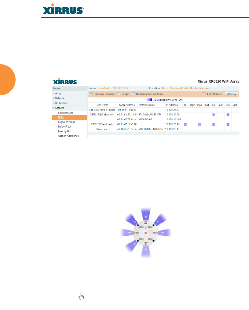
Wireless Array
132 Viewing Status on the Wireless Array
RSSI
For each station that is associated to the Array, the RSSI (Received Signal Strength
Indicator) window shows the station’s RSSI value as measured by each IAP. In
other words, the window shows the strength of the station’s signal at each radio.
You may choose to display Unassociated Stations as well with a checkbox at the
bottom of the window.
Figure 73. Station RSSI Values
By default, the RSSI is displayed numerically. You may display the relative
strength using color if you select Colorize Intensity, with the strongest signals
indicated by the most intense color. (Figure 73) If you select Graph, then the RSSI
is shown on a representation of the Array, either colorized or numerically based
on your selection. (Figure 74) The stations are listed to the left of the Array — click
on a station to show its RSSI values on the Array.
Figure 74. Station RSSI Values — Colorized Graphical View
In either graphical or tabular view, you may sort the rows based on any column
that has an active column header, indicated when the mouse pointer changes to
the hand icon . Click on the Refresh button to refresh the station list, or click in
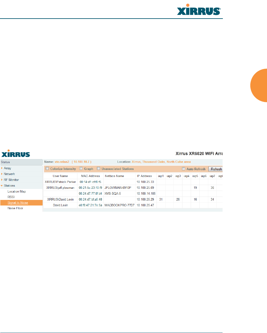
Wireless Array
Viewing Status on the Wireless Array 133
the Auto Refresh check box to instruct the Array to refresh this window
automatically.
See Also
Station Status Windows
RF Monitor Windows
Signal-to-Noise Ratio (SNR)
For each station that is associated to the Array, the Signal-to-Noise Ratio (SNR)
window shows the station’s SNR value as measured by each IAP. In other words,
the window shows the SNR of the station’s signal at each IAP radio. The signal-
to-noise ratio can be very useful for determining the cause of poor performance at
a station. A low value means that action may need to be taken to reduce sources of
noise in the environment and/or improve the signal from the station.
Figure 75. Station Signal-to-Noise Ratio Values
You may choose to display Unassociated Stations as well with a checkbox at the
bottom of the window.
By default, the SNR is displayed numerically. (Figure 75) You may display
the relative value using color if you select Colorize Intensity, with the highest
SNR indicated by the most intense color. (Figure 76) If you select Graph, then
the SNR is shown on a representation of the Array, either colorized or numerically
based on your selection. The stations are listed to the left of the Array — click on a
station to show its SNR values on the Array.

Wireless Array
134 Viewing Status on the Wireless Array
Figure 76. Station SNR Values — Colorized Graphical View
In either graphical or tabular view, you may sort the rows based on any column
that has an active column header, indicated when the mouse pointer changes to
the hand icon . Click on the Refresh button to refresh the station list, or click in
the Auto Refresh check box to instruct the Array to refresh this window
automatically.
See Also
Station Status Windows
RF Monitor Windows
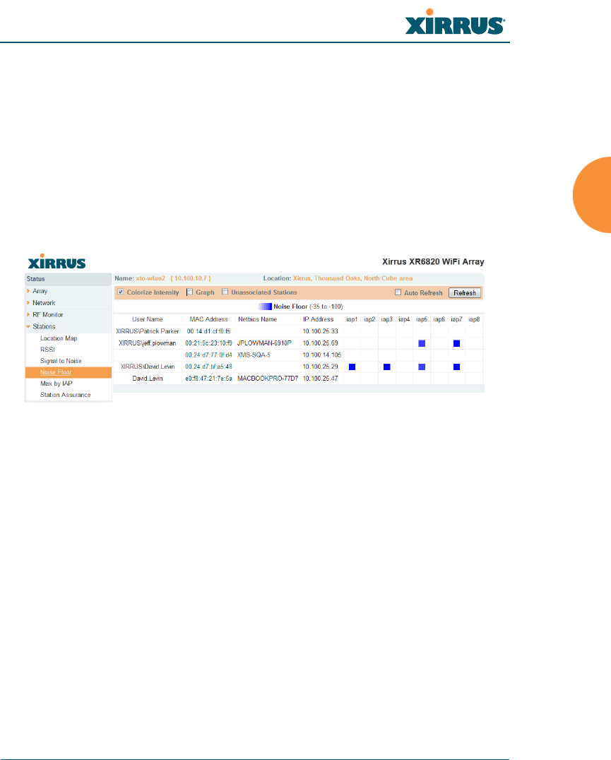
Wireless Array
Viewing Status on the Wireless Array 135
Noise Floor
For each station that is associated to the Array, the Noise Floor window shows
the ambient noise affecting a station’s signal as measured by each IAP. The noise
floor is the RSSI value when the station is not transmitting, sometimes called a
Silence value. In other words, the window shows the noise floor of the station’s
signal at each IAP radio. The noise floor value can be very useful for
characterizing the environment of a station to determine the cause of poor
performance. A relatively high value means that action may need to be taken to
reduce sources of noise in the environment.
Figure 77. Station Noise Floor Values
You may choose to display Unassociated Stations as well with a checkbox at the
bottom of the window.
By default, the noise floor is displayed numerically. (Figure 77) You may display
the relative value using color if you select Colorize Intensity, with the highest
noise indicated by the most intense color. If you select Graph, then the ambient
noise is shown on a representation of the Array, either colorized or numerically
based on your selection.(Figure 78) The stations are listed to the left of the
Array — click on a station to show its values on the Array.

Wireless Array
136 Viewing Status on the Wireless Array
Figure 78. Station Noise Floor Values — Colorized Graphical View
In either graphical or tabular view, you may sort the rows based on any column
that has an active column header, indicated when the mouse pointer changes to
the hand icon . Click on the Refresh button to refresh the station list, or click in
the Auto Refresh check box to instruct the Array to refresh this window
automatically.
See Also
Station Status Windows
RF Monitor Windows
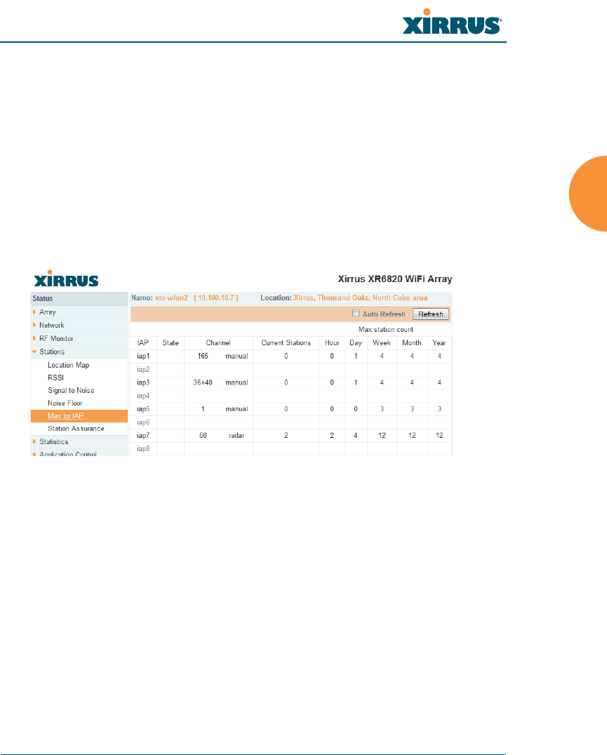
Wireless Array
Viewing Status on the Wireless Array 137
Max by IAP
This status-only window shows the maximum number of client stations that have
historically been associated to the Array. For each IAP, the list shows the IAP’s
state and channel number, the current number of stations associated, and the
highest number of stations that have been associated over various periods of time:
hour, day, week, month, and year. In other words, the Max Station Count shows
the “high water mark” over the selected period of time — the maximum count of
stations for the selected period, rather than a cumulative count of all stations that
have associated. This information aids in network administration and in planning
for additional capacity.
Figure 79. Max by IAP
You may click an IAP to go to the IAP Settings window. Click on the Refresh
button to refresh the station list, or click Auto Refresh to instruct the Array to
refresh this window automatically.
See Also
IAPs
Station Status Windows
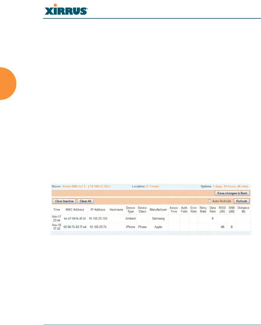
Wireless Array
138 Viewing Status on the Wireless Array
Station Assurance
Station assurance monitors the quality of the connections that users are
experiencing on the wireless network. This window shows client stations that
have had connectivity issues. You may enable or disable the station assurance
feature and set thresholds for the problems that it checks, such as excessive packet
retry or packet error rates, or stations that are unable to stay associated to the
Array. Please see “Station Assurance” on page 320 for more information about
these settings. When the Array detects that a station has reached the threshold
value for one or more of the issues checked, it adds the station to this page. In
addition, an event is triggered, a trap is generated, and a Syslog message is
logged.
For each station, this list shows the MAC address, its IP address, its host name, its
device type, device class, and manufacturer. It also shows the values of the
various statistics that were monitored for problems as described in “Station
Assurance” on page 320: associated time, authentication failures, packet error
rate, packet retry rate, packet data rate, RSSI, signal to noise ratio (SNR), and
distance.
Figure 80. Station Assurance
You may click the Clear Inactive button to remove stations that are no longer
connected to the Array from the list. Click the Clear All button to remove all
entries and start fresh to add problem stations to the list as they are detected.
Click on the Refresh button to refresh the station list, or click Auto Refresh to
instruct the Array to refresh this window automatically.

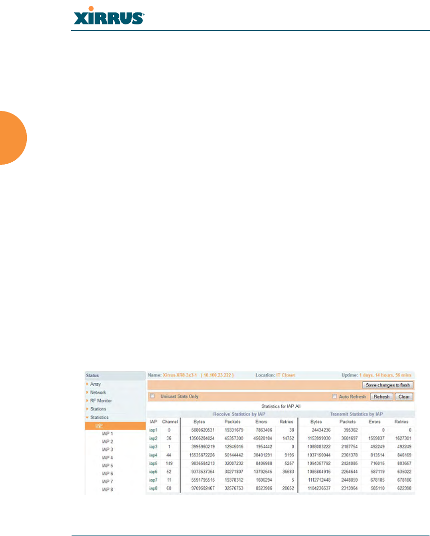
Wireless Array
140 Viewing Status on the Wireless Array
Statistics Windows
The following Array Statistics windows are available:
IAP Statistics Summary — provides an overview of the statistical data
associated with all IAPs. Expands to show links for displaying detailed
statistics for individual IAPs.
Per-IAP Statistics — provides detailed statistics for an individual IAP.
Network Statistics — displays statistical data associated with each
network (Ethernet) interface.
VLAN Statistics — provides statistical data associated with your assigned
VLANs.
WDS Statistics — provides statistical data for all WDS client and host
links.
Filter Statistics — provides statistical data for all configured filters.
Station Statistics — provides statistical data associated with each station.
IAP Statistics Summary
This is a status only window that provides an overview of the statistical data
associated with all IAPs. It also shows the channel used by each IAP. For detailed
statistics for a specific IAP, see “Per-IAP Statistics” on page 141. Click the Unicast
Stats Only checkbox on the lower left to filter the results, or clear the checkbox to
show statistics for all wireless traffic.
Figure 81. IAP Statistics Summary Page

Wireless Array
Viewing Status on the Wireless Array 141
You can Refresh the data (update the window with the latest information) or
Clear the data (reset all content to zero and begin counting again) at any time by
clicking on the appropriate button. You can also click in the Auto Refresh check
box to instruct the Array to refresh this window automatically.
See Also
System Log Window
Global Settings (IAP)
Global Settings .11an
Global Settings .11bgn
IAPs
Per-IAP Statistics
This is a status only window that provides detailed statistics for the selected IAP.
If you click the link for IAP All in the left frame, each detailed statistic field will
show the sum of that statistic for all IAPs. For a summary of statistics for all IAPs,
see “IAP Statistics Summary” on page 140. Use the Display Percentages
checkbox at the lower left to select the output format — check this option to
express each statistic as a percentage of the total at the top of the column, or leave
it blank to display raw numbers.
A quick way to display the statistics for a particular IAP is by clicking the Array
graphic at the bottom left of the WMI window. Click the desired IAP, and the
selected statistics will be displayed. See “User Interface” on page 88.
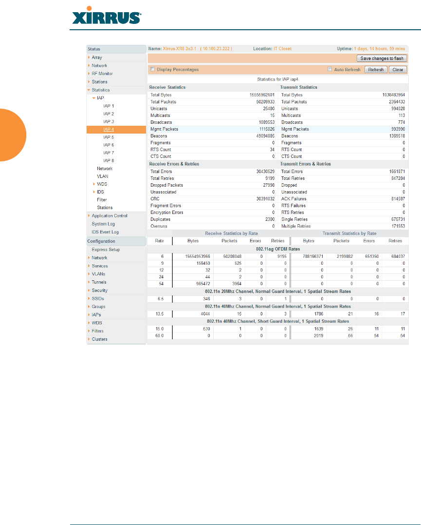
Wireless Array
142 Viewing Status on the Wireless Array
Figure 82. Individual IAP Statistics Page
You can Refresh the data (update the window with the latest information) or
Clear the data (reset all content to zero and begin counting again) at any time by
clicking on the appropriate button. You can also click in the Auto Refresh check
box to instruct the Array to refresh this window automatically.
See Also
System Log Window
Global Settings (IAP)
Global Settings .11an
Global Settings .11bgn
IAPs
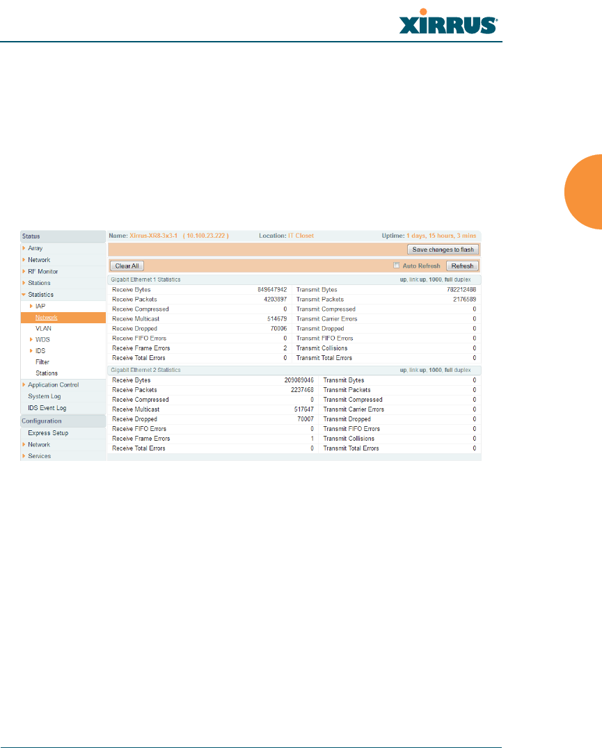
Wireless Array
Viewing Status on the Wireless Array 143
Network Statistics
This is a status only window that allows you to review statistical data associated
with each network (Ethernet) interface and its activity. You can Refresh the data
(update the window with the latest information) or Clear the data (reset all
content to zero and begin counting again) at any time by clicking on the
appropriate button. You can also click in the Auto Refresh check box to instruct
the Array to refresh this window automatically. If you are experiencing problems
on the Array, you may also want to print this window for your records
.
Figure 83. Network Statistics
See Also
DHCP Server
DNS Settings
Network
Network Interfaces
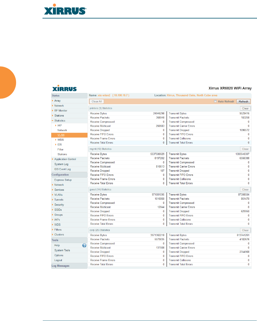
Wireless Array
144 Viewing Status on the Wireless Array
VLAN Statistics
This is a status only window that allows you to review statistical data associated
with your assigned VLANs. You can refresh the information that is displayed on
this page at any time by clicking on the Refresh button, or select the Auto Refresh
option for this window to refresh automatically. The Clear All button at the lower
left allows you to clear (zero out) all VLAN statistics.
Figure 84. VLAN Statistics
See Also
VLAN Management
VLANs
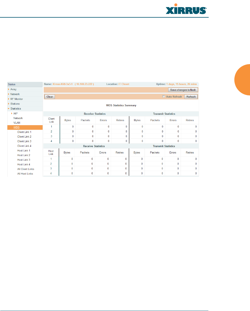
Wireless Array
Viewing Status on the Wireless Array 145
WDS Statistics
The main WDS Statistics window provides statistical data for all WDS client and
host links. To access data about a specific WDS client or host link, simply click on
the desired link in the left frame to access the appropriate window. You may also
choose to view a sum of the statistics for all client links, all host links, or all links
(both client and host links).
Figure 85. WDS Statistics
See Also
SSID Management
WDS
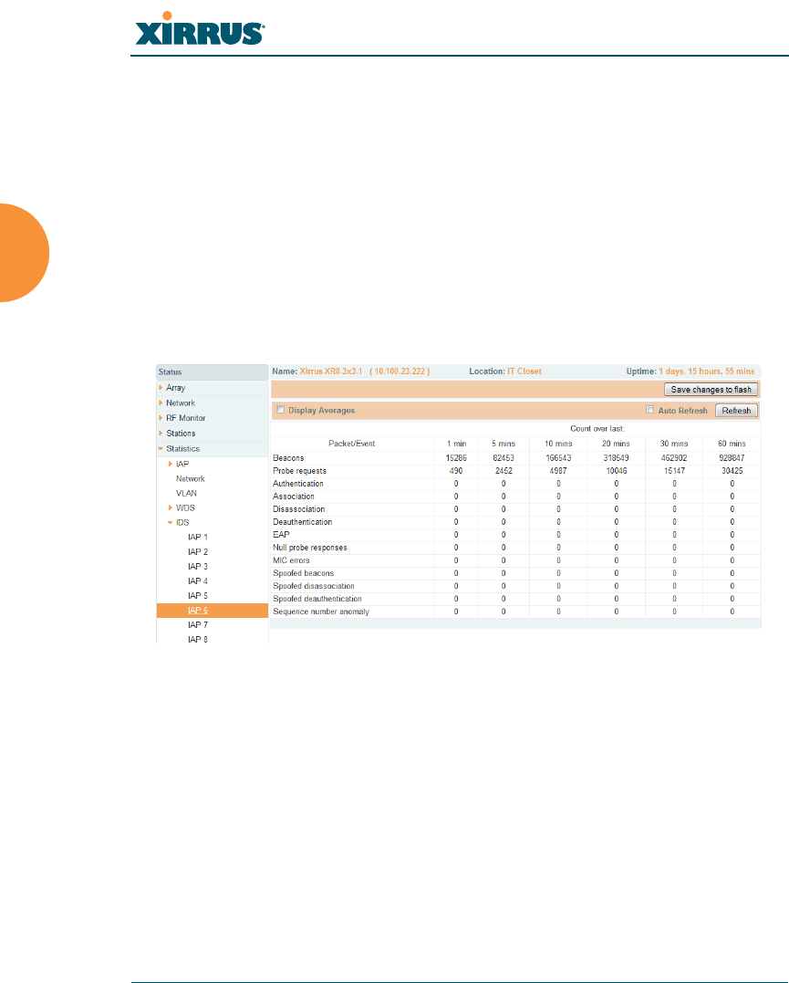
Wireless Array
146 Viewing Status on the Wireless Array
IDS Statistics
The Xirrus Array employs a number of IDS/IPS (Intrusion Detection System/
Intrusion Prevention System) strategies to detect and prevent malicious attacks on
the wireless network. This status-only window provides detailed intrusion
detection statistics for the selected IAP. Use the Display Averages checkbox at the
upper left to select the output format — check this option to express each statistic
as an average rate, or leave it blank to display raw counts.
Note that you must have Intrusion Detection Mode enabled to collect IDS
statistics. See “Intrusion Detection” on page 328. Information about IDS events is
discussed in the “IDS Event Log Window” on page 157
Figure 86. IDS Statistics Page
You can Refresh the data (update the window with the latest information) at any
time by clicking on the appropriate button. You can also click in the Auto Refresh
check box to instruct the Array to refresh this window automatically.
See Also
Intrusion Detection
IDS Event Log Window
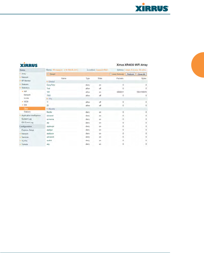
Wireless Array
Viewing Status on the Wireless Array 147
Filter Statistics
The Filter Statistics window provides statistical data for all configured filters. The
name, state (enabled — on or off), and type (allow or deny) of each filter is shown.
For enabled filters, this window shows the number of packets and bytes that met
the filter criteria. Click on a column header to sort the rows based on that column.
Click on a filter name to edit the filter settings.
Figure 87. Filter Statistics
See Also
Filters
Application Control Windows
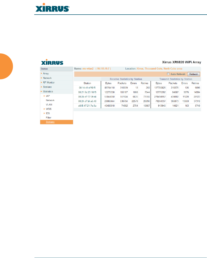
Wireless Array
148 Viewing Status on the Wireless Array
Station Statistics
This status-only window provides an overview of statistical data for all stations.
Stations are listed by MAC address, and Receive and Transmit statistics are
summarized for each. For detailed statistics for a specific station, click the desired
MAC address in the Station column and see “Per-Station Statistics” on page 149.
Figure 88. Station Statistics
Note that you can clear the data for an individual station (see Per-Station
Statistics), but you cannot clear the data for all stations using this window.
You can Refresh the data (update the window with the latest information) at any
time by clicking on the appropriate button. You can also click in the Auto Refresh
check box to instruct the Array to refresh this window automatically.
See Also
Per-Station Statistics
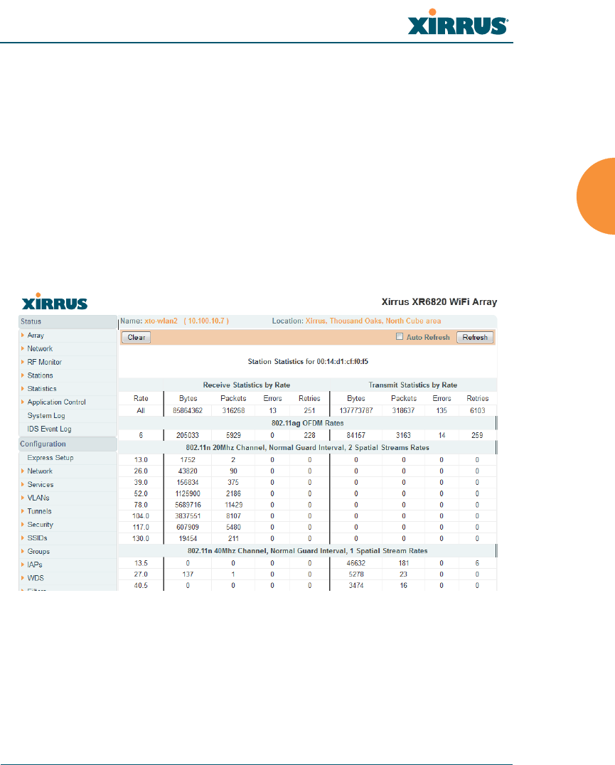
Wireless Array
Viewing Status on the Wireless Array 149
Per-Station Statistics
This window provides detailed statistics for the selected station. This window is
accessed from the Station Statistics window — click the MAC address of the
desired entry in the Station column to display its Per-Station Statistics window.
Receive and Transmit statistics are listed by Rate — this is the data rate in Mbps.
For a summary of statistics for all stations, see “Station Statistics” on page 148.
You can Refresh the data (update the window with the latest information) or
Clear the data (reset all content to zero and begin counting again) at any time by
clicking on the appropriate button. You can also click in the Auto Refresh check
box to instruct the Array to refresh this window automatically.
Figure 89. Individual Station Statistics Page
See Also
Station Statistics

Wireless Array
150 Viewing Status on the Wireless Array
Application Control Windows
The Application Control feature provides real-time visibility of application usage
by users across the wireless network. Network usage has changed enormously in
the last few years, with the increase in smartphone and tablet usage stressing
networks. Increasing traffic from legitimate business needs such as cloud- and
web-based applications, streaming media and VoIP must be handled with an
adequate quality of experience.
Application Control is discussed in the following topics:
About Application Control — an overview of this feature.
Application Control — displays information about applications running
on the wireless network.
Stations (Application Control) — displays a list of stations. Click one to
analyze application control information for only that station.
About Application Control
The Array uses Deep Packet Inspection (DPI) to determine what applications are
being used and by whom, and how much bandwidth they are consuming. These
applications are rated by their degree of risk and productiveness. Filters may then
be put in place to implement per-application policies that keep network usage
focused on productive uses:
Usage of non-productive and risky applications like BitTorrent can be
restricted using Filters.
Traffic for mission-critical applications like VoIP and WebEx may be given
higher priority (QoS).
Non- critical traffic from applications like YouTube may be given lower
priority (QoS).
This feature is only available if the Array license includes Application
Control. See “About Licensing and Upgrades” on page 361.
Application Control data is only available from XR Series Array models. It
is not available on XN Arrays.
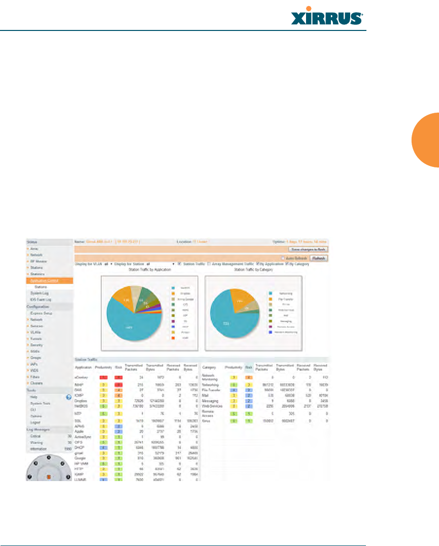
Wireless Array
Viewing Status on the Wireless Array 151
Traffic flows for specific applications may be controlled by sending them
into VLANs that are designated for that type of traffic.
Application Control can track application usage over time to monitor trends.
Usage may be tracked by Array, VLAN, or station. Many hundreds of
applications are recognized and grouped into a number of categories. The
distributed architecture of Xirrus Arrays allows Application Control to scale
naturally as you grow the network.
Application Control
This display-only window provides a snapshot of the application usage on your
Array. In order to view the Application Control window, the Array must have a
licence that supports this feature, and you must have enabled the Application
Control option on the Filter Lists page (see“Filter Lists” on page 345).
Figure 90. Application Control

Wireless Array
152 Viewing Status on the Wireless Array
The Application Control window has three sections:
Selection Criteria allow you to choose the type of data to show, and to
filter for a single VLAN or station.
Pie Charts present a color coded at-a-glance view of the top ten
applications being used by the network.
Traffic Tables beneath the pie charts list the applications in use along
with traffic statistics. Unique Productivity and Risk ratings let you easily
assess the nature of applications in use, so that you can take action using
Filter Management.
Selection Criteria
At the top of the window, the options in the gray ribbon allow you to customize
the display with the following choices:
Display for VLAN: Use the drop-down list if you wish to select just one
VLAN to analyze, or leave the default value of all to see data from all
VLANs.
Display for Station: Use the drop-down list if you wish to select just one
station to analyze (stations are listed by their MAC address), or leave the
default value of all to see data from all stations. You may also use the
Stations window to select a station to display. See “Stations (Application
Control)” on page 155.
Station Traffic: Check this box if you wish to analyze traffic from stations,
listing the applications that they are using.
Array Management Traffic: Check this box if you wish to analyze
management traffic on this Array, including the load due to functions
such as Xirrus Roaming. Tracking traffic into the array on the
management side can alert you to nefarious activity—and even to traffic
on the wired network that would best be blocked before it hits the Array.
You may display both station and Array management traffic, if you wish.
By Application: Check this box if you wish to analyze and list traffic by
what specific applications are in use, such as WebEx or BitTorrent.
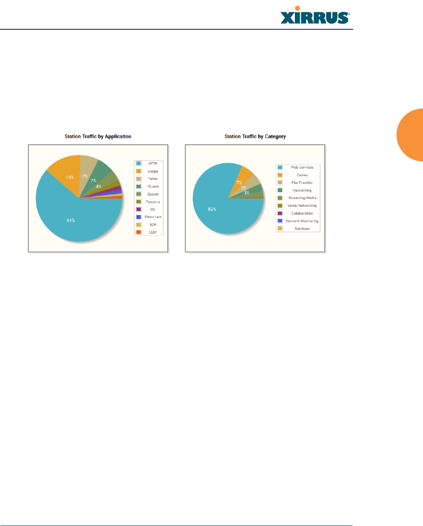
Wireless Array
Viewing Status on the Wireless Array 153
By Category: Check this box if you wish to analyze and list traffic by
what types of applications are in use, such as Games or Collaboration.
Auto Refresh instructs the Array to periodically refresh this window
automatically. Use the Refresh button to refresh the window right now.
Pie Charts
Figure 91. Application Control (Pie Charts)
These charts provide a quick way to determine how your wireless bandwidth is
being used. There are charts for Station Traffic and/or Array Management
Traff i c , depending on which checkboxes you selected. Similarly, there are charts
for By Application and/or By Category, depending on your selections. The top
ten applications or categories are listed, by percentage of bandwidth usage.
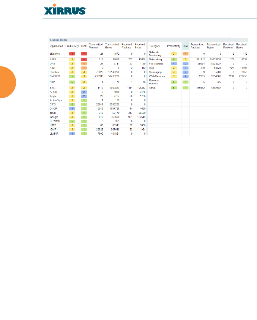
Wireless Array
154 Viewing Status on the Wireless Array
Traffic Tables
Figure 92. Application Control (Station Traffic)
These tables provide detailed information about how your wireless bandwidth is
being used. There are tables for Station Traffic and/or Array Management
Traff i c , depending on which checkboxes you selected. Similarly, there are tables
for By Application and/or By Category, depending on your selections.
In addition to showing traffic statistics, there are two unique and highly useful
columns. Risk estimates the likelihood of an application causing problems for
your business, such as a file-sharing utility introducing viruses or exposing you to
legal problems. Risk is rated from 1 (low risk, e.g., Google) to 5 (high risk, e.g.,
BitTorrent). Risky applications (rated at 4 or 5) are flagged for your attention by
highlighting the entry in pale red. Productivity estimates the value of an activity
to your business, from 1 (unproductive, e.g., Y8 gaming site) to 5 (productive, e.g.,
WebEx).
You may click the heading of any column to sort based on that column. Click
again to sort in the reverse order. For instance, sort on Risk to find problem
applications, or sort on Productivity to find applications that should be given
increased or decreased handling priority.
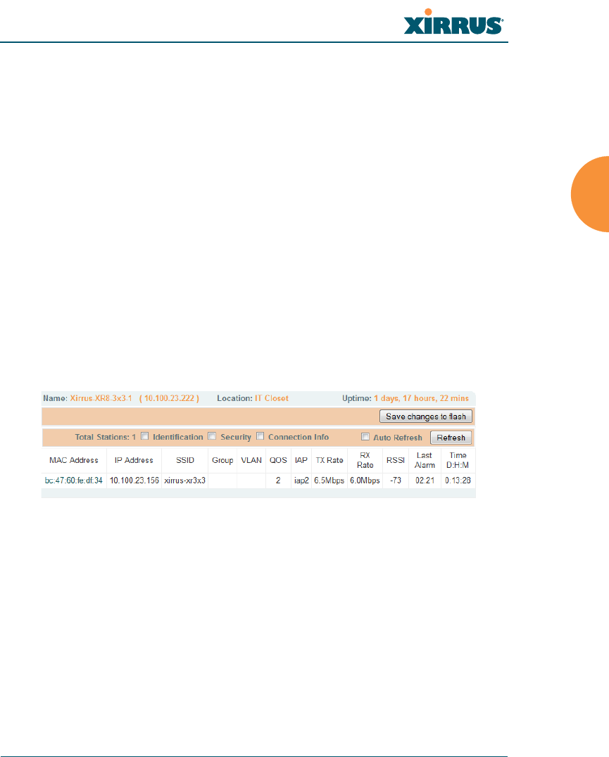
Wireless Array
Viewing Status on the Wireless Array 155
When you find risky or unproductive applications taking up bandwidth on the
network, you can easily create Filters to control them. See “Filter Management”
on page 347. You may use filters to:
Block problematic traffic, such as BitTorrent or Y8.
Prioritize mission critical traffic—by increasing the QoS assigned to the
traffic. See “Understanding QoS Priority on the Wireless Array” on
page 244.
Lower the priority of less productive traffic—use filters to decrease the
QoS assigned to traffic for applications like YouTube and Facebook.
Stations (Application Control)
This status-only window shows client stations currently visible to the Array.
The MAC address in the first column is a link. Click on a selected station, and the
Application Control window opens with the Display for Station field set to that
station, to perform a detailed analysis of its application usage.
Figure 93. Stations (Application Control)
The rest of the fields and display options on this window (including the
Identification, Security, and Connection Info checkboxes) are as described in
“Stations” on page 126.
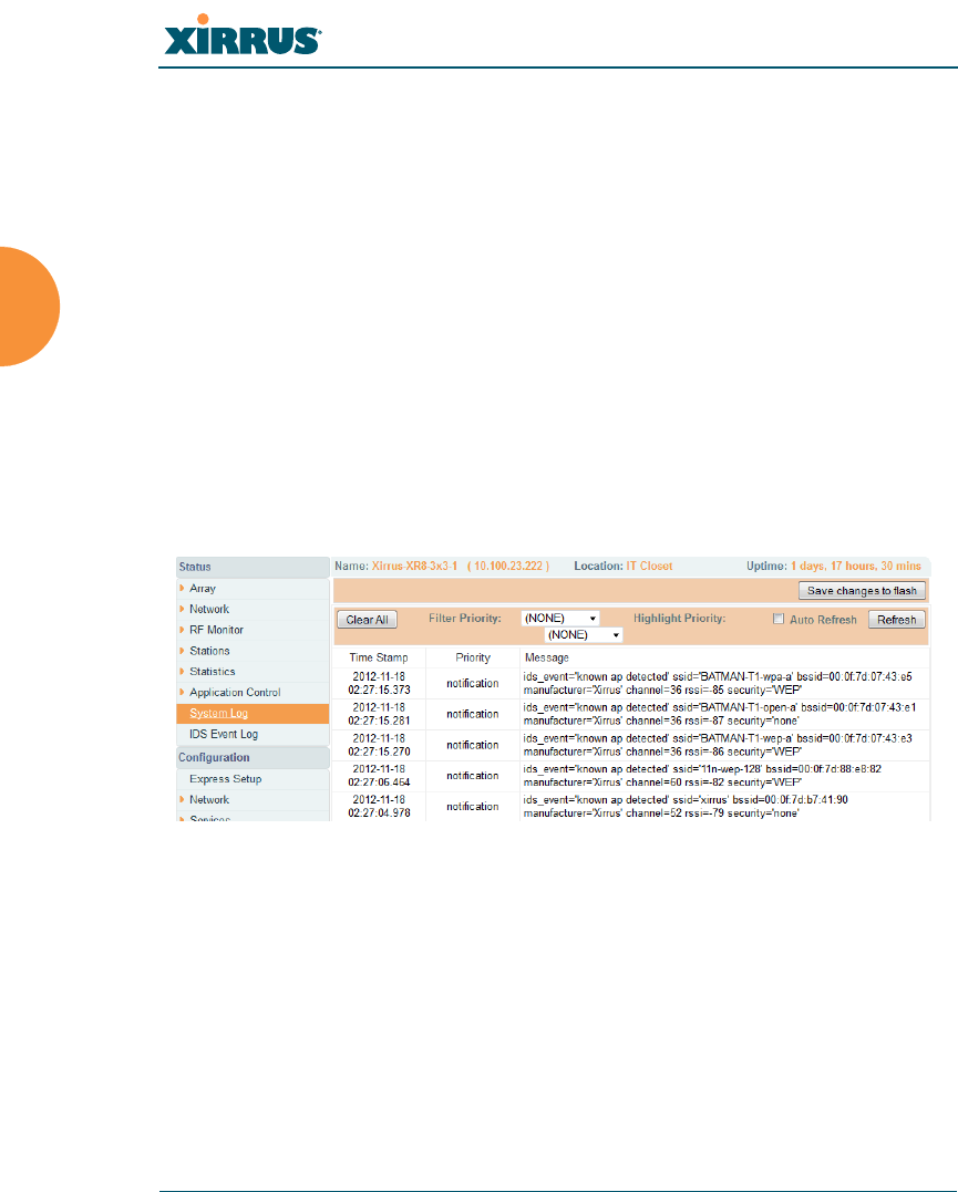
Wireless Array
156 Viewing Status on the Wireless Array
System Log Window
This is a status only window that allows you to review the system log, where
system alerts and messages are displayed. Although there are no configuration
options available in this window, you do have the usual choice of deciding how
the event messages are sorted by clicking in the column header for the desired
field (Time Stamp, Priority, or Message).
Time Stamp — sorts the list based on the time the event occurred.
Priority — sorts the list based on the priority assigned to the message.
Message — sorts the list based on the message category
The displayed messages may be filtered by using the Filter Priority option, which
allows control of the minimum priority level displayed. For example, you may
choose (under Services >System Log) to log messages at or above Debug level
but use Filter Priority to display only those at Information level and above.
Figure 94. System Log (Alert Level Highlighted)
Use the Highlight Priority field if you wish to highlight messages at the selected
priority level. Click on the Refresh button to refresh the message list, or click on
the Clear All button at the upper left to delete all messages. You can also click in
the Auto Refresh check box to instruct the Array to refresh this window
automatically.
Note that there is a shortcut way to view system log messages. If you click Log
Messages near the bottom of the left hand frame, WMI displays counts of log
messages at different severity levels. Click a count to display just those messages
in the System Log window. See Figure 42 on page 88 for more information.
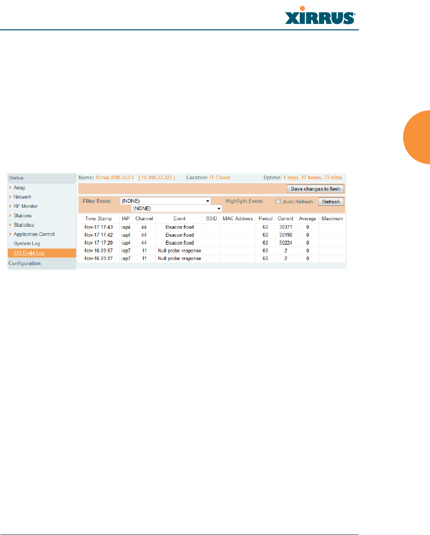
Wireless Array
Viewing Status on the Wireless Array 157
IDS Event Log Window
This status only window displays the Intrusion Detection System (IDS) Event log,
listing any detected attacks on your network. For descriptions of the types of
attacks detected, as well as the settings to fine-tune IDS on the Array, please see
“Intrusion Detection” on page 328.
The displayed messages may be filtered by using the Filter Event setting, which
allows you to select just one type of intrusion to display. For example, you may
choose to display only beacon flood attacks.
Figure 95. IDS Event Log
Use the Highlight Event field if you wish to highlight all events of one particular
type in the list. Click on the Refresh button to refresh the message list, or click the
Auto Refresh check box to instruct the Array to refresh this window
automatically.
Although there are no configuration options available in this window, you do
have the usual choice of deciding how the event messages are sorted by clicking
in the column header for the desired field.
Time Stamp — the time that the event occurred.
IAP — the affected radio.
Channel — the affected channel.
Event — the type of attack, as described in Intrusion Detection.
SSID — the SSID that was attacked.
MAC Address — the MAC address of the attacker.

Wireless Array
158 Viewing Status on the Wireless Array
Period — the length of the window used to determine whether the count
of this type of event exceeded the threshold.
Current — the count of this type of event for the current period.
Average — the average count per period of this type of event.
Maximum — the maximum count per period of this type of event.

Wireless Array
Configuring the Wireless Array 159
Configuring the Wireless Array
The following topics include procedures for configuring the Array using the
product’s embedded Web Management Interface (WMI). Procedures have been
organized into functional areas that reflect the flow and content of the WMI.
The following WMI windows allow you to establish configuration parameters for
your Array, and include:
“Express Setup” on page 161
“Network” on page 169
“Services” on page 184
“VLANs” on page 199
“Tunnels” on page 204
“Security” on page 208
“SSIDs” on page 242
“Groups” on page 264
“IAPs” on page 271
“WDS” on page 338
“Filters” on page 344
“Clusters” on page 352
After making changes to the configuration settings of an Array you must click on
the Save changes to flash button at the top of the configuration window,
otherwise the changes you make will not be applied the next time the Array is
rebooted.
Some settings are only available if the Array’s license includes appropriate
Xirrus Advanced Feature Sets. If a setting is unavailable (grayed out),
then your license does not support the feature. See “About Licensing and
Upgrades” on page 361.

Wireless Array
160 Configuring the Wireless Array
Note that the Configuration menu section may be collapsed down to hide the
headings under it by clicking it. Click again to display the headings. (See
Figure 43 on page 89.)
This chapter only discusses using the configuration windows on the Array. To
view status or use system tools on the Array, please see:
“Viewing Status on the Wireless Array” on page 95
“Using Tools on the Wireless Array” on page 359
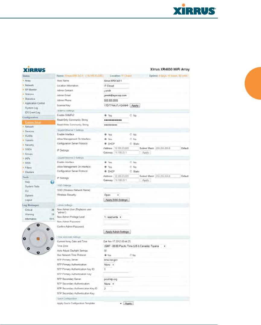
Wireless Array
Configuring the Wireless Array 161
Express Setup
Use the Express Setup page to establish global configuration settings that enable
basic Array functionality. Any changes you make in this window will affect all
radios.
Figure 96. WMI: Express Setup

Wireless Array
162 Configuring the Wireless Array
When finished, click Save changes to flash if you wish to make your changes
permanent.
Procedure for Performing an Express Setup
1. Host Name: Specify a unique host name for this Array. The host name is
used to identify the Array on the network. Use a name that will be
meaningful within your network environment, up to 64 alphanumeric
characters. The default is the Array’s serial number.
2. Location Information: Enter a brief but meaningful description that
accurately defines the physical location of the Array. In an environment
where multiple units are installed, clear definitions for their locations are
important if you want to identify a specific unit.
3. Admin Contact: Enter the name and contact information of the person
who is responsible for administering the Array at the designated location.
4. Admin Email: Enter the email address of the admin contact you entered
in Step 3.
5. Admin Phone: Enter the telephone number of the admin contact you
entered in Step 3.
6. License Key: If Xirrus issued you a license that differs from the current
value shown, enter it now.
7. Configure SNMPv2: Select whether to Enable SNMPv2 on the Array,
and set the SNMPv2 community strings. The factory default value for the
Read-Only Community String is xirrus_read_only. The factory default
value for the Read-Write Community String is xirrus. If you are using
the Xirrus Management System (XMS), the read-write string must match
the string used by XMS. XMS also uses the default value xirrus.
8. Configure the Gigabit Ethernet network interface settings. Please see
“Network Interfaces” on page 171 for more information. For XN Arrays,
configure the 10/100 Ethernet 0 (10/100 Mb) port as well.
The fields for each of these interfaces are similar, and include:

Wireless Array
Configuring the Wireless Array 163
a. Enable Interface: Choose Yes to enable this network interface, or
choose No to disable the interface.
b. Allow Management on Interface: Choose Yes to allow management
of the Array via this Gigabit interface, or choose No to deny all
management privileges for this interface. Note that for XN Arrays,
the 10/100 Ethernet port is also known as the Management Port, and
management is always enabled on this port.
c. Configuration Server Protocol: Choose DHCP to instruct the Array
to use DHCP to assign IP addresses to the Array’s Ethernet interfaces,
or choose Static if you intend to enter IP addresses manually. If you
choose the Static IP option, you must enter the following IP Settings:
•Address: Enter a valid IP address for this Array. To use a remote
connection (Web, SNMP, or SSH), a valid IP address must be
used.
•Subnet Mask: Enter a valid IP address for the subnet mask (the
default is 255.255.255.0). The subnet mask defines the number of
IP addresses that are available on the routed subnet where the
Array is located.
•Default Gateway: Enter a valid IP address for the default
gateway. This is the IP address of the router that the Array uses
to forward data to other networks.
•Click the Apply button for this interface when done making IP
changes.
9. SSID Settings: This section specifies the wireless network name and
security settings.
a. The SSID (Wireless Network Name) is a unique name that identifies
a wireless network (SSID stands for Service Set Identifier). All devices
attempting to connect to a specific WLAN must use the same SSID.
The default SSID is xirrus. Entering a value in this field will replace
the default SSID with the new name.
For additional information about SSIDs, go to the Multiple SSIDs
section of “Frequently Asked Questions” on page 452.

Wireless Array
164 Configuring the Wireless Array
b. Wireless Security: Select the desired wireless security scheme (Open,
WEP or WPA). Make your selection from the choices available in the
pull-down list.
•Open — This option offers no data encryption and is not
recommended, though you might choose this option if clients are
required to use a VPN connection through a secure SSH utility,
like PuTTy.
•WEP (Wired Equivalent Privacy) — An optional IEEE 802.11
function that offers frame transmission privacy similar to a wired
network. WEP generates secret shared encryption keys that both
source and destination stations can use to alter frame bits to
avoid disclosure to eavesdroppers.
•WPA (Wi-Fi Protected Access) — A Wi-Fi Alliance standard that
contains a subset of the IEEE 802.11i standard, using TKIP or AES
as an encryption method and 802.1x for authentication. WPA is
the stronger of the two wireless security schemes.
•WPA2 (Wi-Fi Protected Access 2) — WPA2 is the follow-on
security method to WPA for wireless networks and provides
stronger data protection and network access control. It offers
Enterprise and consumer Wi-Fi users with a high level of
assurance that only authorized users can access their wireless
networks. Like WPA, WPA2 is designed to secure all versions of
802.11 devices, including 802.11a, 802.11b, 802.11g, and 802.11n,
multi-band and multi-mode.
•WPA-Both (WPA and WPA2) — This option makes use of both
WPA and WPA2.
For more information about security, including a full review of all
security options and settings, go to “Understanding Security” on
page 209.
c. WEP Encryption Key/Passphrase: Depending on the wireless
security scheme you selected, enter a unique WEP key or WPA
passphrase. This field and the one below only appear if you select a
Wireless Security option other than Open.

Wireless Array
Configuring the Wireless Array 165
d. Confirm Encryption Key/Passphrase: If you entered a WEP key or
WPA passphrase, confirm it here.
e. Click Apply SSID Settings when done.
10. Admin Settings: This section allows you to change the default admin
username, password, and privileges for the Array. You may change the
password and leave the user name as is, but we suggest that you change
both to improve Array security.
a. New Admin User (Replaces user “admin”): Enter the name of a new
administrator user account. Be sure to record the new account name
and password, because the default admin user will be deleted! Note
that the Array also offers the option of authenticating administrators
using a RADIUS server (see “Admin Management” on page 214)).
b. New Admin Privilege Level: By default, the new administrator will
have read/write privileges on the Array (i.e., the new user will be
able to change the configuration of the Array). If you wish the new
account to have different privileges, select the desired level from the
drop-down list. For more information about user privileges, please
see “Admin Privileges” on page 216. Take care to make sure to leave
yourself enough read/write privileges on at least one account to be
able to administer the Array.
c. New Admin Password: Enter a new administration password for
managing this Array. If you forget this password, you must reset the
Array to its factory defaults so that the password is reset to admin (its
default setting).
d. Confirm Admin Password: If you entered a new administration
password, confirm the new password here.
e. Click Apply Admin Settings when done.
11. Time and Date Settings: Specify an optional time (NTP - Network Time
Protocol) server or modify the system time if you’re not using a server.
a. Current Array Date and Time: This read-only field shows the current
time for your convenience.

Wireless Array
166 Configuring the Wireless Array
b. Time Zone: Select your time zone from the choices available in the
pull-down list.
c. Auto Adjust Daylight Savings: If you are not using NTP, check this
box if you want the system to adjust for daylight savings
automatically, otherwise leave this box unchecked (default).
d. Use Network Time Protocol: Check this box if you want to use an
NTP server to synchronize the Array’s clock. Use of NTP is
mandatory for Arrays to be managed with XMS (the Xirrus
Management System), and ensures that Syslog time-stamping is
maintained across all units. Without using an NTP server (no
universal clock), each Array will use its own internal clock and stamp
times accordingly, which may result in discrepancies. If you select
Yes, the NTP server fields are displayed. If you don’t want to use an
NTP server, select No (default) and set the system time on the Array
manually.
e. NTP Primary Server: If you are using NTP, enter the IP address or
domain name of the NTP server.
f. NTP Primary Authentication: (optional) If you are using
authentication with NTP, select the type of key: MD5 or SHA1. Select
None if you are not using authentication (this is the default). For
more information on authenticated NTP, see “Time Settings (NTP)”
on page 185.
g. NTP Primary Authentication Key ID: Enter the key ID, which is a
decimal integer.
h. NTP Primary Authentication Key: Enter your key, which is a string
of characters.
i. NTP Secondary Server: Enter the IP address or domain name of an
optional secondary NTP server to be used in case the Array is unable
to contact the primary server. You may use the authentication fields
as described above if you wish to set up authentication for the
secondary server.

Wireless Array
Configuring the Wireless Array 167
j. Adjust Time (hrs:min:sec): If you are not using NTP, check this box if
you want to adjust the current system time. When the box is checked,
the time fields become active. Enter the revised time (hours, minutes,
seconds, am/pm) in the corresponding fields. If you don’t want to
adjust the current time, this box should be left unchecked (default).
k. Adjust Date (month/day/year): If you are not using NTP, check this
box if you want to adjust the current system date. When the box is
checked, the date fields become active. Enter the revised date (month,
day and year) in the corresponding fields. If you don’t want to adjust
the current date, this box should be left unchecked (default).
12. Quick Configuration: This offers predefined configuration options such
as Classroom and High-Density that capture best practices from years of
field experience. If one of the options in the drop-down list is appropriate
to your deployment, select it and click Apply. For example, the High-
Density option uses best practices to configure the Array for high density
settings such as lecture halls, convention centers, stadiums, etc.
13. IAP Settings:
Enable/Configure All IAPs: Click on the Execute button to enable and
auto configure all IAPs (a message displays the countdown time — in
seconds — to complete the auto-configuration task). When an IAP is
enabled, its LED is switched on.
Figure 97. LEDs are Switched On
LED on

Wireless Array
168 Configuring the Wireless Array
14. Click Save changes to flash at the upper right to make your changes
permanent, i.e., these settings will still be in effect after a reboot.
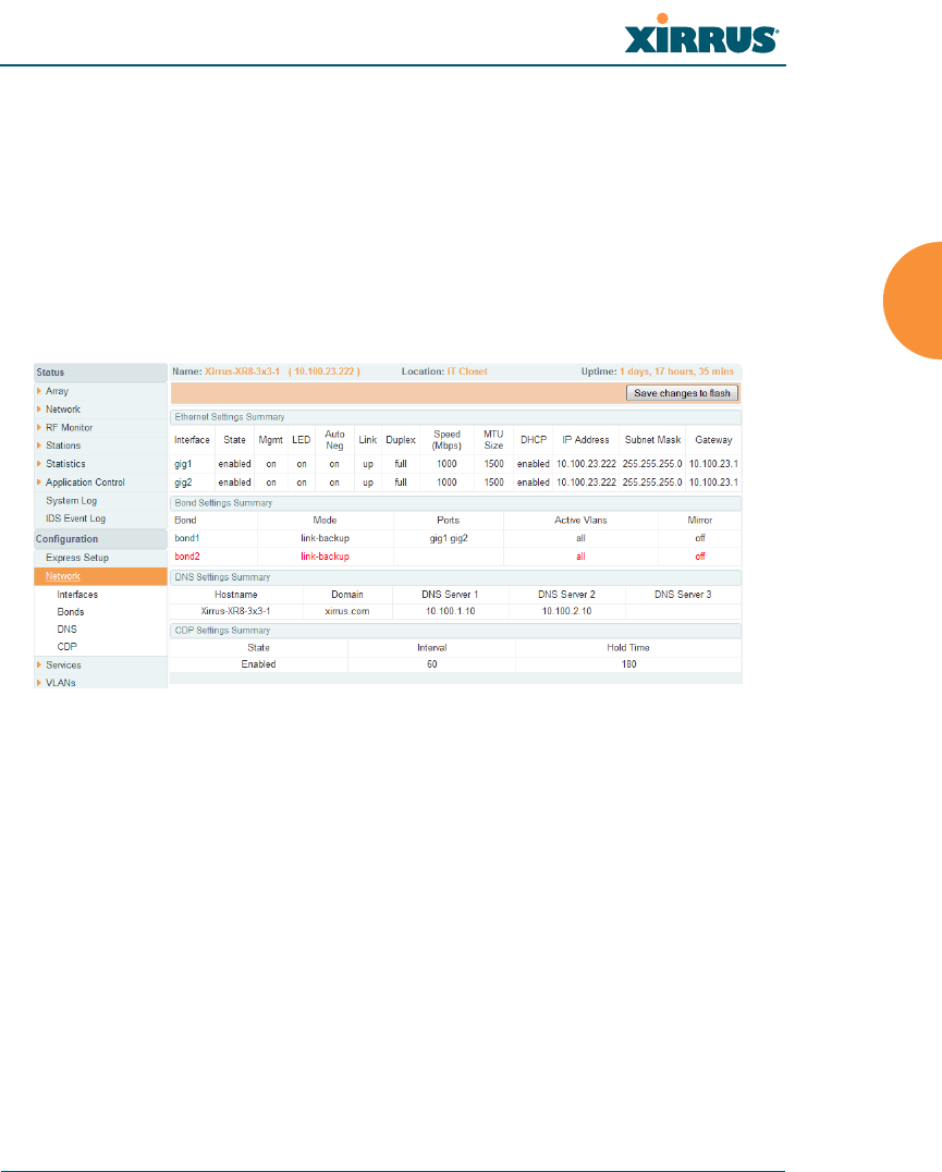
Wireless Array
Configuring the Wireless Array 169
Network
This is a status-only window that provides a snapshot of the configuration
settings currently established for the Ethernet interfaces. DNS Settings and CDP
Settings (Cisco Discovery Protocol) are summarized as well. You must go to the
appropriate configuration window to make changes to any of the settings
displayed here (configuration changes cannot be made from this window). You
can click on any item in the Interface column to “jump” to the associated
configuration window.
Figure 98. Network Interfaces
WMI windows that allow you to change or view configuration settings associated
with the network interfaces include:
“Network Interfaces” on page 171
“Network Bonds” on page 175
“DNS Settings” on page 181
“CDP Settings” on page 183
See Also
DNS Settings
Network Interfaces
Network Status Windows

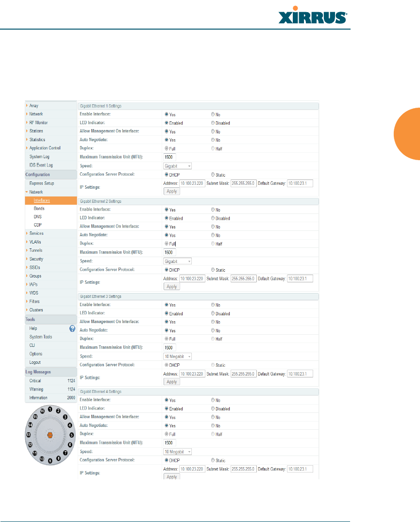
Wireless Array
Configuring the Wireless Array 171
Network Interfaces
XR500, XR-1000, and XR-2000 Series Arrays have one Gigabit Ethernet interface,
while XR-4000 Series Arrays have two, and XR-6000 Series models have four. This
window allows you to establish configuration settings for these interfaces.
Figure 99. Network Settings
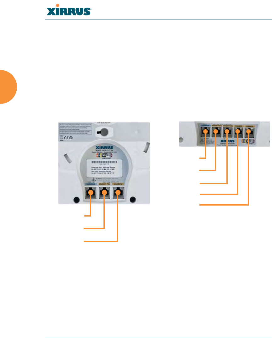
Wireless Array
172 Configuring the Wireless Array
On XN Series Arrays, this window configures the 10/100 Fast Ethernet interface
and the Gigabit 1 and Gigabit2 interfaces
When finished making changes, click Save changes to flash if you wish to make
your changes permanent. When the status of a port changes, a Syslog entry is
created describing the change.
Network Interface Ports
The following diagram shows the location of network interface ports on the
underside of an XR Series Array.
Figure 100. Network Interface Ports
Procedure for Configuring the Network Interfaces
Configure the Gigabit network interfaces (for XN Arrays, configure the Fast
Ethernet port as well). The fields for each of these interfaces are the same, and
include:
1. Enable Interface: Choose Yes to enable this network interface, or choose
No to disable the interface.
XR-6000 Series
Console
Gigabit1 POE
Gigabit2
Console
Gigabit1 POE
Gigabit2 POE
Gigabit3
Gigabit4
XR-4000 Series

Wireless Array
Configuring the Wireless Array 173
2. LED Indicator: Choose Enabled to allow the LED for this interface to
blink with traffic on the port, or choose Disabled to turn the LED off.
The LED will still light during the boot sequence, then turn off. This
option is only available for the Gigabit interfaces.
3. Allow Management on Interface: Choose Yes to allow management of
this Array via the selected network interface, or choose No to deny all
management privileges for this interface. For XN Arrays, this option is
only available for the Gigabit interfaces — management is always enabled
on the 10/100 interface (sometimes called the Management Port).
4. Auto Negotiate: This feature allows the Array to negotiate the best
transmission rates automatically. Choose Yes to enable this feature, or
choose No to disable this feature — the default is enabled. If you disable
the Auto Negotiate feature, you must define the Duplex and Speed
options manually (otherwise these options are not available). Both sides
of the link must have the same values for the following settings, or the
connection will have errors.
a. Duplex: Full-duplex mode transmits data in two directions
simultaneously (for example, a telephone is a full-duplex device
because both parties can talk and be heard at the same time). Half-
duplex allows data transmission in one direction at a time only (for
example, a walkie-talkie is a half-duplex device). If the Auto-
Negotiate feature is disabled, you can manually choose Half or Full
duplex for your data transmission preference.
b. MTU: the Maximum Transmission Unit size. This is the largest packet
size (in bytes) that the interface can pass along.
c. Speed: If the Auto-Negotiate feature is disabled, you must manually
choose the desired data transmission speed from the pull-down list.
For XN Arrays, when configuring the Fast Ethernet interface the
options are 10 Megabit or 100 Megabit. For configuring the Gigabit
interfaces the options are 10 Megabit or 100 Megabit. (Note that 1000
Megabit speed can only be set by Auto-Negotiation.)

Wireless Array
174 Configuring the Wireless Array
5. Configuration Server Protocol / IP Settings: Choose DHCP to instruct
the Array to use DHCP when assigning IP addresses to the Array, or
choose Static IP if you intend to enter IP addresses manually. If you select
the Static IP option you must specify the IP address, IP subnet mask and
default gateway.
a. Address: If you selected the Static IP option, enter a valid IP address
for the Array. To use any of the remote connections (Web, SNMP, or
SSH), a valid IP address must be established.
b. Subnet Mask: If you selected the Static IP option, enter a valid IP
address for the subnet mask (the default for Class C is 255.255.255.0).
The subnet mask defines the number of IP addresses that are
available on the routed subnet where the Array is located.
c. Default Gateway: If you selected the Static IP option, enter a valid IP
address for the default gateway. This is the IP address of the router
that the Array uses to send data to other networks. (You don’t need to
enter the gateway if it is on the same subnet as the Array.)
d. Click the Apply button for this interface when done making IP
changes.
6. Static Route (IP Address/Mask): (For XN Arrays, Fast Ethernet port
only) The 10-100 Ethernet Port may be used for managing the Array out
of band from the Gigabit Ethernet ports. The 10-100 port will route only
management traffic, using a static route that may be configured using this
field.
7. When done configuring all interfaces as desired, click Save changes to
flash if you wish to make your changes permanent.
See Also
Network Bonds
DNS Settings
Network
Network Statistics
Spanning Tree Status
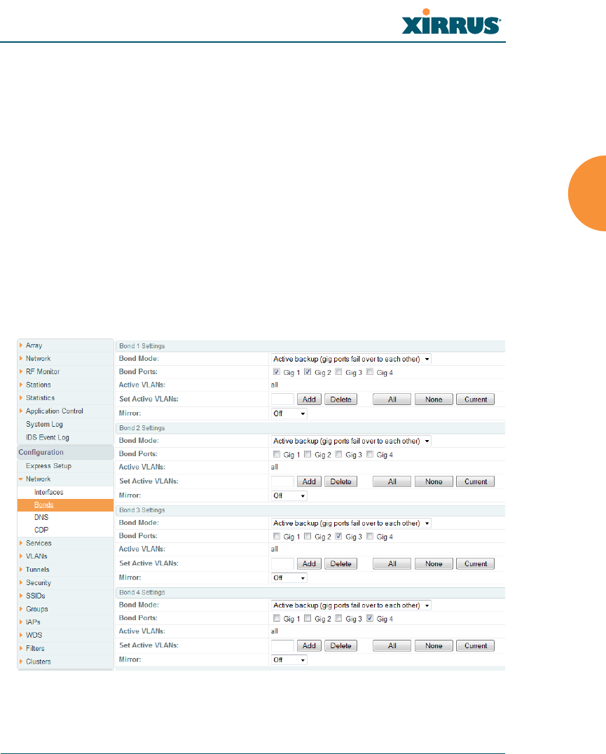
Wireless Array
Configuring the Wireless Array 175
Network Bonds
On models with more than one Gigabit port these ports may be bonded, i.e.
configured to work together in sets. For example, one port may provide active
backup or load balancing for another, or other options as described in this section.
XR-6000 Series Arrays have four Gigabit ports, and you may specify which ports
are bonded to work together as a pair. You may also select more than two ports to
work together in one group.
You may use the mirror option to have all the traffic that is ingressing and
egressing one bond be transmitted by the bond you are configuring. For example,
if you configure Bond2 to mirror Bond1, then all traffic going in and out of
Bond1’s Gigabit ports will be transmitted out of Bond2’s Gigabit ports. This way
of duplicating one bond’s traffic to another bond is very useful for
troubleshooting with a network analyzer.
Figure 101. Network Bonds

Wireless Array
176 Configuring the Wireless Array
Procedure for Configuring Network Bonds
Configure the bonding behavior of the Gigabit network interfaces. The fields for
each of these bonds are the same, and include:
1. Bond Mode: Select the desired behavior for a set of bonded Gigabit
Ethernet ports from the following options.
The modes below describe the relationship between a set of Gigabit
ports—for example, load balancing or active backup. Use the Bond Ports
field to select the ports that are bonded (set in Step 2). Two or more ports
may be bonded. You may also include just one single port in a bond—this
is useful for mirroring one Gigabit port to another port (Step 5 on
page 180). In Arrays that have four Gigabit ports, you have the option of
bonding three or four ports together. In this discussion, we call two ports
that are bonded Gigx and Gigy.
a. Active Backup (gig ports fail over to each other) — This mode
provides fault tolerance and is the default mode. Gigx acts as the
primary link. Gigy is the backup link and is passive. Gigy assumes
the IP properties of Gigx. If Gigx fails, the Array automatically fails
over to Gigy. When a failover occurs in this mode, Gigy issues
gratuitous ARPs to allow it to substitute for Gigx at Layer 3 as well as
Layer 2. See Figure 102 (a). You may include more than two ports in
the bond with Active Backup to provide additional fault tolerance.
For example, if you have three Gigabit ports configured in a bond, if
the first two ports in the bond were to go down, the Array would fail
over traffic to the third Gigabit port.
If a set of Gigabit ports have been bonded, the IP address, IP mask, IP
gateway, IP DHCP, and Management settings are shared between bonded
ports. Any changes you make to these settings on one member will be
reflected in the settings of the other members. Other settings may be
configured individually.
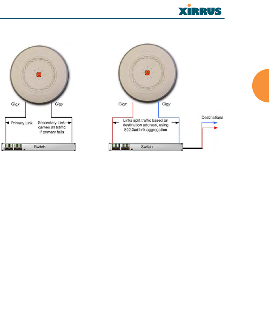
Wireless Array
Configuring the Wireless Array 177
Figure 102. Port Modes (a, b)
b. Aggregate Traffic from gig ports using 802.3ad — The Array sends
network traffic across all member Gigabit ports to increase link speed
to the network. These ports act as a single logical interface, using a
load balancing algorithm to balance traffic across the ports. For non-
IP traffic (such as ARP), the last byte of the destination MAC address
is used to do the calculation. If the packet is a fragment or not TCP or
UDP, the source and destination IP addresses are used to do the
calculation. If the packet is TCP or UDP over IP then the source IP
address, destination IP address, source port number and destination
port number are all used to do the calculation. The network switch
must also support 802.3ad. If a port fails, the connection degrades
gracefully — the other port still transmits. See Figure 102 (b).
c. Transmit Traffic on all gig ports — Transmits incoming traffic on all
Gigabit ports. Any traffic received on Gigabit ports is sent to the
onboard processor. This mode provides fault tolerance. See
Figure 103 (c).
(a) Active backup (b) Aggregate using 802.3ad
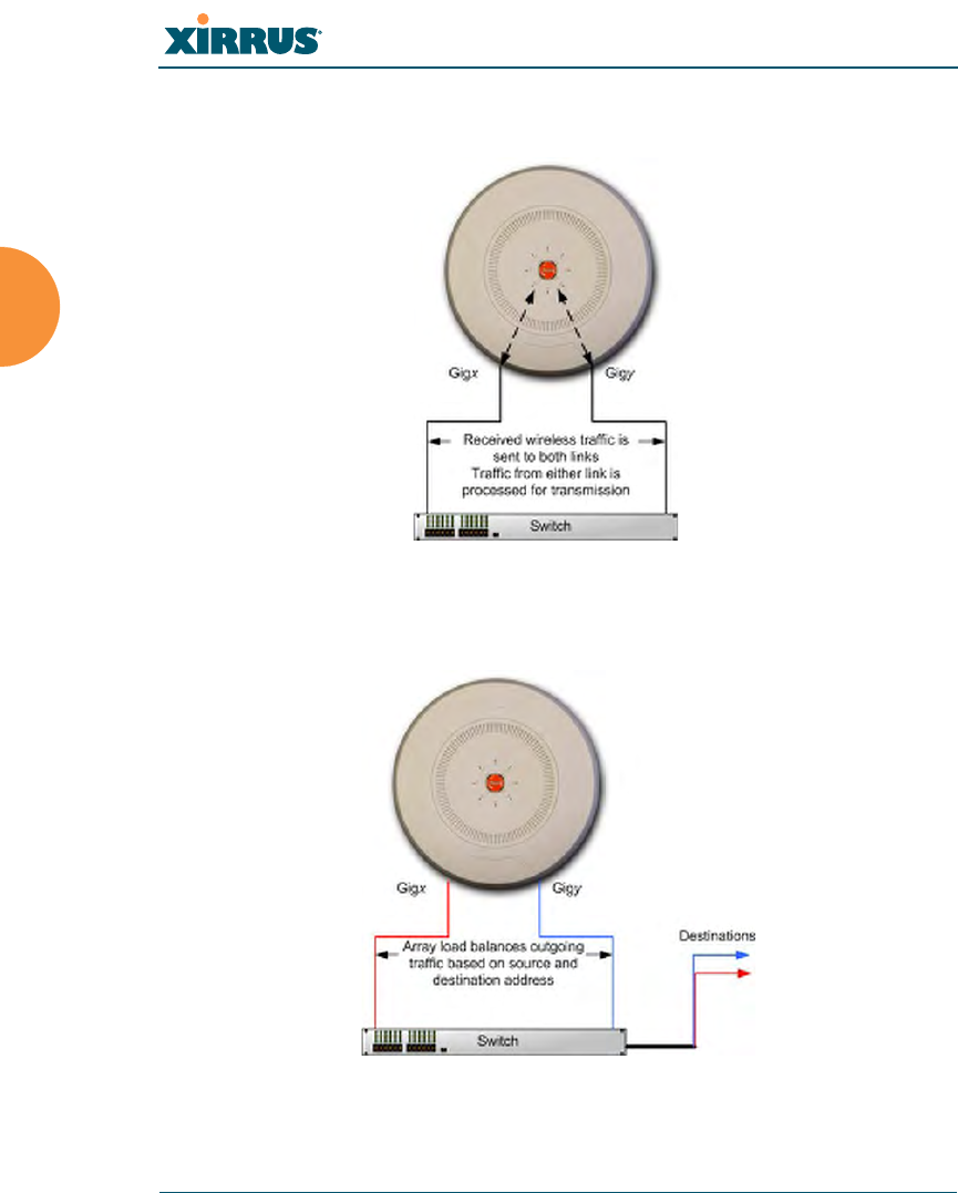
Wireless Array
178 Configuring the Wireless Array
Figure 103. Port Modes (c)
Figure 104. Port Modes (d)
(c) Transmit on all ports
(d) Load balance traffic

Wireless Array
Configuring the Wireless Array 179
d. Load balance traffic between gig ports — This option provides
trunking, similar to option (b) — Aggregate Traffic from gig1 & gig2
using 802.3ad, but it does not use 802.3ad and it uses a different load
balancing algorithm to determine the outgoing Gigabit port. The
outgoing port used is based on an exclusive OR of the source and
destination MAC address. Like option (b), this mode also provides
load balancing and fault tolerance. See Figure 104 (d).
2. Bond Ports: Select the ports to be members of this bond for the behavior
specified by Bond Mode. By default, Bond1 contains Gig1 and Gig2. You
may also set up a bond with a single port, for example, if you wish to
mirror one Gigabit port to another. In Arrays that have four Gigabit ports,
you also have the option of bonding three or four ports together.
When you check off a port to be a member of a bond, that port is
automatically removed from any other bonds that contain it.
3. Active VLANs: Active VLANs is a read-only field that shows the VLANs
that you have selected to be passed through this port. You may modify
this list by making selections in Set Active VLANs.
4. Set Active VLANs: Create and manage the list of VLANs that are
allowed to be passed through this port. Traffic will be dropped for
VLANs that are not in this list. You may view the complete list of VLANs
whose traffic will be passed in the Active VLANs list, above. The default
setting is to pass All VLANs.
a. To add a VLAN to the list of allowed VLANs, type its name or
number, and click Add. To allow all VLANs (current or future) to be
passed, click the All button.
b. To remove a VLAN from the list of allowed VLANs, type its name or
number, and click Delete. To remove all VLANs from the Active
VLANs list, click None.
c. To allow only the set of currently defined VLANs (see “VLANs” on
page 199) to be passed, click the Current button. Essentially, this
“fixes” the Active VLANs list to contain the Array’s currently defined
VLANs, and only this set, until you make explicit changes to the
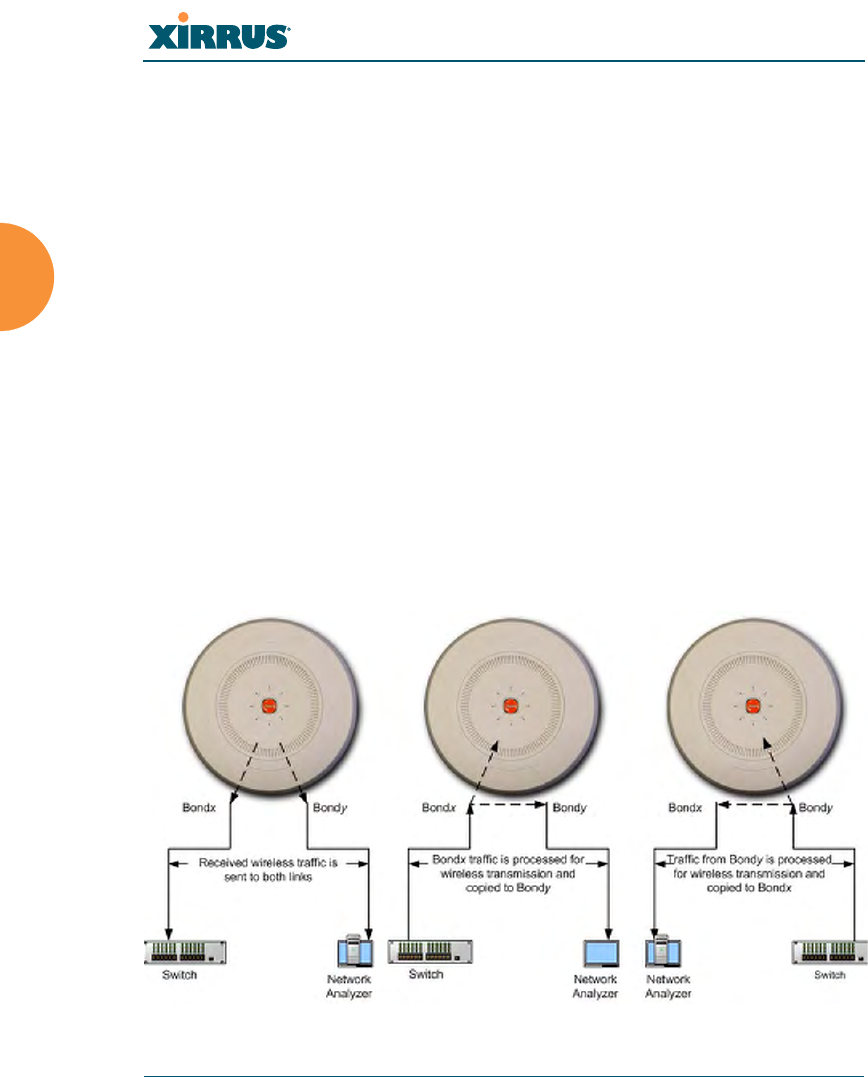
Wireless Array
180 Configuring the Wireless Array
Active VLANs list. If you create new VLANs, they will not be passed
unless you take action to add them to the list.
5. Mirror — Specify one of the active bonds (Bondx) that is to be mirrored by
this bond (Bondy). (Figure 105) All wireless traffic received on the Array
is transmitted out both Bondx and Bondy. All traffic received on Bondx is
passed on to the onboard processor as well as out Bondy. All traffic
received on Bondy is passed on to the onboard processor as well as out
Bondx. This allows a network analyzer to be plugged into Bondy to
capture traffic for troubleshooting, while the bonded ports provide
network connectivity for data traffic.
Mirroring is also used to duplicate the traffic from one bond to another
bond — traffic received on Bondx is transmitted by Bondy; similarly,
traffic received on Bondy is transmitted by Bondx. This allows the Array
to act as a wired bridge and allows Arrays to be daisy-chained and still
maintain wired connectivity.
If each bond contains just one port as is the case for XN Arrays, then you
have the simple case of one port mirroring another.
Figure 105. Mirroring Traffic
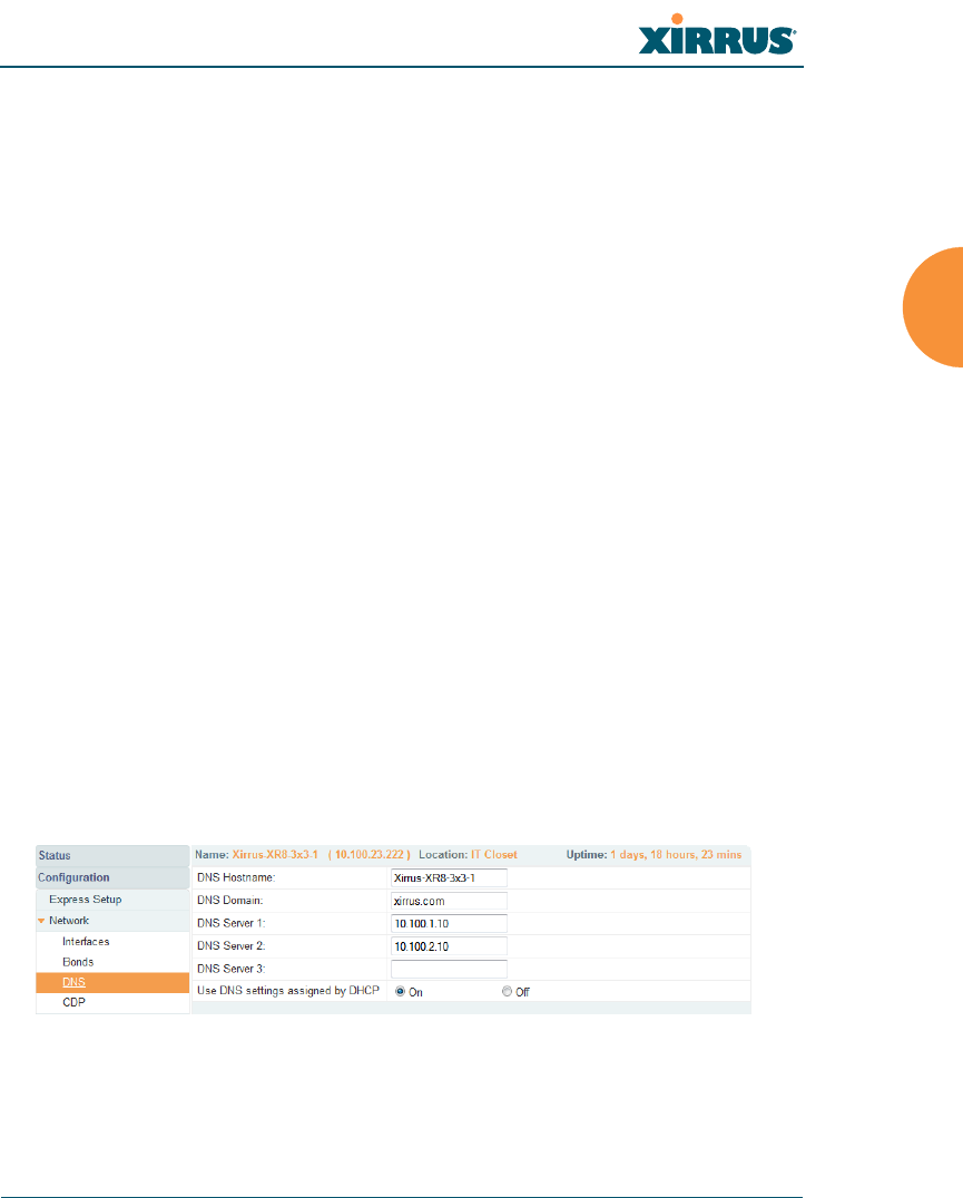
Wireless Array
Configuring the Wireless Array 181
6. When done configuring bonds as desired, click Save changes to flash if
you wish to make your changes permanent.
See Also
Network Interfaces
DNS Settings
Network
Network Statistics
Spanning Tree Status
DNS Settings
This window allows you to establish your DNS (Domain Name System) settings.
The Array uses these DNS servers to resolve host names into IP addresses. The
Array also registers its own Host Name with these DNS servers, so that others
may address the Array using its name rather than its IP address. An option allows
you to specify that the Array’s DNS servers will be assigned via a DHCP server
on the wired network.
Note that the DNS servers defined here are not used by wireless clients — servers
for stations associated to the Array are defined along with DHCP pools. See
“DHCP Server” on page 197. At least one DNS server must be set up if you want
to offer clients associating with the Array the ability to use meaningful host
names instead of numerical IP addresses. When finished, click Save changes to
flash if you wish to make your changes permanent.
Figure 106. DNS Settings

Wireless Array
182 Configuring the Wireless Array
Procedure for Configuring DNS Servers
1. DNS Host Name: Enter a valid DNS host name.
2. DNS Domain: Enter the DNS domain name.
3. DNS Server 1: Enter the IP address of the primary DNS server.
4. DNS Server 2 and DNS Server 3: Enter the IP address of the secondary
and tertiary DNS servers (if required).
5. Use DNS settings assigned by DHCP: If you are using DHCP to assign
the Array’s IP address, you may turn this option On. The Array will then
obtain its DNS domain and server settings from the network DHCP
server that assigns an IP address to the Array, rather than using the DNS
Server fields above. You may also configure that DHCP server to assign a
host name to the Array.
6. Click Save changes to flash if you wish to make your changes
permanent.
See Also
DHCP Server
Network
Network Interfaces
Network Statistics
Spanning Tree Status
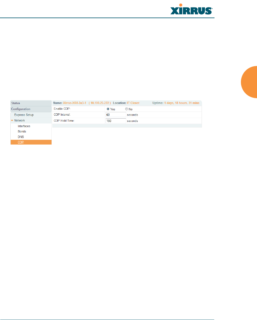
Wireless Array
Configuring the Wireless Array 183
CDP Settings
CDP (Cisco Discovery Protocol) is a layer 2 network protocol used to share
information (such as the device manufacturer and model, network capabilities,
and IP address) with other directly connected network devices. Wireless Arrays
can both advertise their presence by sending CDP announcements, and gather
and display information sent by neighbors (see “CDP Neighbors” on page 111).
This window allows you to establish your CDP settings. When finished, Save
changes to flash if you wish to make your changes permanent.
Figure 107. CDP Settings
Procedure for Configuring CDP Settings
1. Enable CDP: When CDP is enabled, the Array sends out CDP
announcements of the Array’s presence, and gathers CDP data sent by
neighbors. When disabled, it does neither. CDP is enabled by default.
2. CDP Interval: The Array sends out CDP announcements advertising its
presence at this interval. The default is 60 seconds.
3. CDP Hold Time: CDP information received from neighbors is retained
for this period of time before aging out of the Array’s neighbor list. Thus,
if a neighbor stops sending announcements, it will no longer appear on
the CDP Neighbors window after CDP Hold Time seconds from its last
announcement. The default is 180 seconds.
See Also
CDP Neighbors
Network
Network Interfaces
Network Statistics
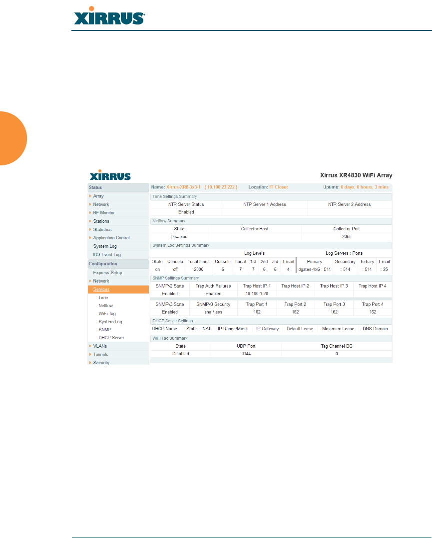
Wireless Array
184 Configuring the Wireless Array
Services
This is a status-only window that allows you to review the current settings and
status for services on the Array, including DHCP, SNMP, Syslog, and Network
Time Protocol (NTP) services. For example, for the DHCP server, it shows each
DHCP pool name, whether the pool is enabled, the IP address range, the gateway
address, lease times, and the DNS domain being used. There are no configuration
options available in this window, but if you are experiencing issues with network
services, you may want to print this window for your records.
Figure 108. Services
The following sections discuss configuring services on the Array:
“Time Settings (NTP)” on page 185
“NetFlow” on page 187
“Wi-Fi Tag” on page 188
“System Log” on page 190
“SNMP” on page 194
“DHCP Server” on page 197
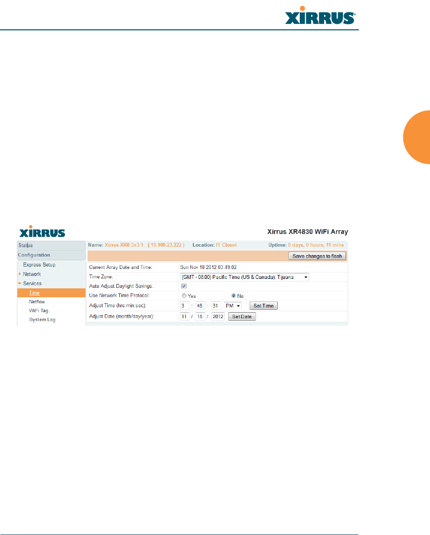
Wireless Array
Configuring the Wireless Array 185
Time Settings (NTP)
This window allows you to manage the Array’s time settings, including
synchronizing the Array’s clock with a universal clock from an NTP (Network
Time Protocol) server. We recommend that you use NTP for proper operation of
SNMP in XMS (the Xirrus Management System), since a lack of synchronization
will cause errors to be detected. Synchronizing the Array’s clock with an NTP
server also ensures that Syslog time-stamping is maintained across all units.
It is possible to use authentication with NTP to ensure that you are receiving
synchronization from a known source. For example, the instructions for
requesting a key for the NIST Authenticated NTP server are available at
http://www.nist.gov/pml/div688/grp00/upload/ntp_instructions.pdf.
The Array allows you to enter optional authentication information.
Figure 109. Time Settings (Manual Time)
Procedure for Managing the Time Settings
1. Current Array Date and Time: Shows the current time for your
convenience.
2. Time Zone: Select the time zone you want to use (normally your local
time zone) from the pull-down list.
3. Auto Adjust Daylight Savings: Check this box if you want the system to
adjust for daylight savings automatically, otherwise leave this box
unchecked (default).
4. Use Network Time Protocol: select whether to set time manually or use
NTP to manage system time.
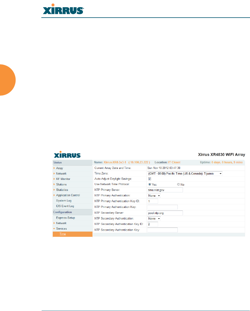
Wireless Array
186 Configuring the Wireless Array
5. Setting Time Manually
a. Adjust Time (hrs:min:sec): If you are not using NTP, check this box if
you want to adjust the current system time. When the box is checked,
you may enter a revised time (hours, minutes, seconds, am/pm) in
the corresponding fields. If you don’t want to adjust the current time,
this box should be left unchecked (default).
b. Adjust Date (month/day/year): If you are not using NTP, check this
box if you want to adjust the current system date. When the box is
checked, you may enter a revised date (month, day and year) in the
corresponding fields. If you don’t want to adjust the current date, this
box should be left unchecked (default).
6. Using an NTP Server
a. NTP Primary Server: If you are using NTP, enter the IP address or
domain name of the NTP server.
Figure 110. Time Settings (NTP Time Enabled)
b. NTP Primary Authentication: (optional) If you are using
authentication with NTP, select the type of key: MD5 or SHA1. Select
None if you are not using authentication (this is the default).
c. NTP Primary Authentication Key ID: Enter the key ID, which is a
decimal integer.
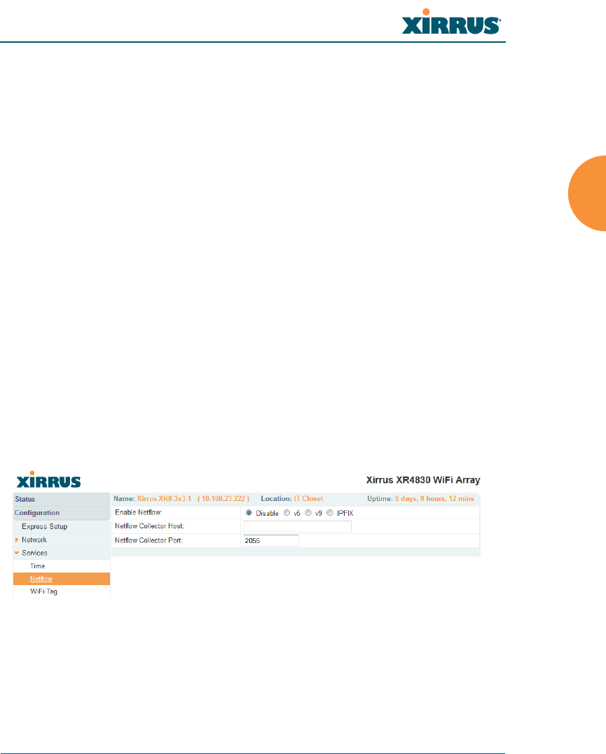
Wireless Array
Configuring the Wireless Array 187
d. NTP Primary Authentication Key: Enter your key, which is a string
of characters.
e. NTP Secondary Server: Enter the IP address or domain name of an
optional secondary NTP server to be used in case the Array is unable
to contact the primary server. You may use the authentication fields
as described above if you wish to set up authentication for the
secondary server.
See Also
Express Setup
Services
SNMP
System Log
NetFlow
This window allows you to enable or disable the sending of NetFlow information
to a designated collector. NetFlow is a proprietary but open network protocol
developed by Cisco Systems for collecting IP traffic information. When NetFlow
is enabled, the Array will send IP flow information (traffic statistics) to the
designated collector.
Figure 111. NetFlow
NetFlow sends per-flow network traffic information from the Array. Network
managers can use a NetFlow collector to view the statistics on a per-flow basis
and use this information to make key decisions. Knowing how many packets and
bytes are sent to and from certain IP addresses or across specific network
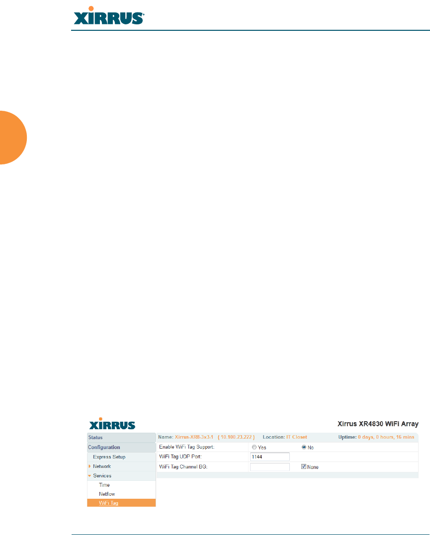
Wireless Array
188 Configuring the Wireless Array
interfaces allows administrators to track usage by various areas. Traffic flow
information may be used to engineer networks for better performance.
Procedure for Configuring NetFlow
1. Enable NetFlow: Select one of the Netflow versions to enable NetFlow
functionality: v5, v9, or IPFIX. Internet Protocol Flow Information Export
(IPFIX) is an IETF protocol (www.ietf.org) performing many of the same
functions as Netflow. Choose Disable if you wish to disable this feature.
2. NetFlow Collector Host (Domain or IP): If you enabled NetFlow, enter
the domain name or IP address of the collector.
3. NetFlow Collector Port: If you enabled NetFlow, enter the port on the
collector host to which to send data.
Wi-Fi Tag
This window enables or disables Wi-Fi tag capabilities. When enabled, the Array
listens for and collects information about Wi-Fi RFID tags sent on the designated
channel. These tags are transmitted by specialized tag devices (for example,
AeroScout Tags). A Wi-Fi tagging server (such as AeroScout) then queries the
Array for a report on the tags that it has received. The Wi-Fi tagging server uses
proprietary algorithms to determine locations for devices sending tag signals.
Figure 112. Wi-Fi Tag
Some features, such as Netflow, are only available if the Array’s license
includes the Xirrus Advanced RF Analysis Manager (RAM). If a setting
is unavailable (grayed out), then your license does not support the feature.
See “About Licensing and Upgrades” on page 361.

Wireless Array
Configuring the Wireless Array 189
Procedure for Configuring Wi-Fi Tag
1. Enable Wi-Fi Tag: Choose Yes to enable Wi-Fi tag functionality, or choose
No to disable this feature.
2. Wi-Fi Tag UDP Port: If you enabled Wi-Fi tagging, enter the port on the
Array which the Wi-Fi tagging server will use to query the Array for
tagging data. When queried, the Array will send back information on the
tags it has observed. For each, the Array sends information such as the
MAC address of the tag transmitting device, and the RSSI and noise floor
observed.
3. Wi-Fi Tag Channel: If you enabled Wi-Fi tagging, enter the 802.11
channel on which the Array will listen for tags. The tag devices must be
set up to transmit on this channel. Only one channel may be configured,
and it must be an 802.11b/g channel in the range of Channel 1 to 11.
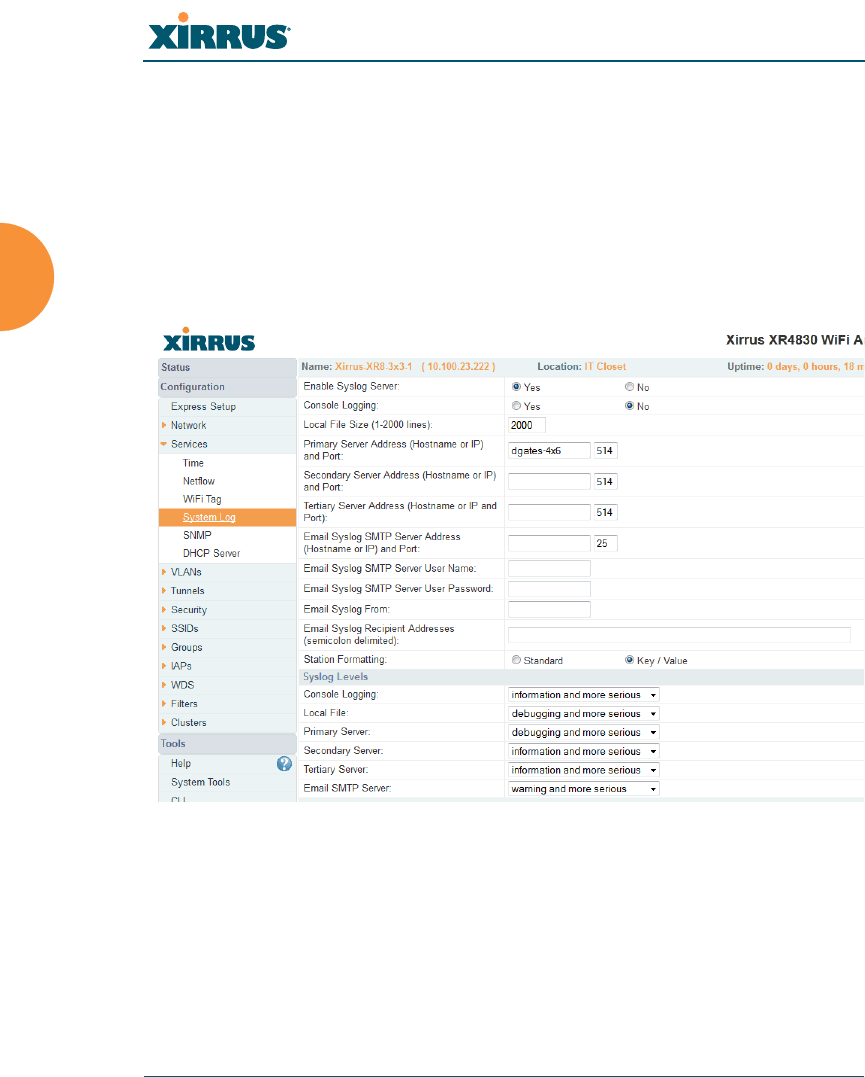
Wireless Array
190 Configuring the Wireless Array
System Log
This window allows you to enable or disable the Syslog server, define primary,
secondary, and tertiary servers, set up email notification, and set the level for
Syslog reporting for each server and for email notification — the Syslog service
will send Syslog messages at the selected severity or above to the defined Syslog
servers and email address. An option allows you to use a Splunk application to
analyze Array events by sending data in key:value pairs, as described in “About
Using the Splunk Application for Xirrus Arrays” on page 193.
Figure 113. System Log
Procedure for Configuring Syslog
1. Enable Syslog Server: Choose Yes to enable Syslog functionality, or
choose No to disable this feature.
2. Console Logging: If you enabled Syslog, select whether or not to echo
Syslog messages to the console as they occur. If you enable console
logging, be sure to set the Console Logging level (see Step 8 below).

Wireless Array
Configuring the Wireless Array 191
3. Local File Size (1-2000 lines): Enter a value in this field to define how
many Syslog records are retained locally on the Array’s internal Syslog
file. The default is 2000.
4. Primary Server Address (Hostname or IP) and Port: If you enabled
Syslog, enter the hostname or IP address of the primary Syslog server.
You may also change the port used on the server if you do not wish to use
514, the default port.
5. Secondary/Tertiary Server Address (Hostname or IP) and Port:
(Optional) If you enabled Syslog, you may enter the hostname or IP
address of one or two additional Syslog servers to which messages will
also be sent. You may also change the port used on each server if you do
not wish to use 514, the default port. You may set one of the server
addresses to the address of a server for Splunk (see “About Using the
Splunk Application for Xirrus Arrays” on page 193).
6. Email Notification: (Optional) The following parameters allow you to
send an email to a designated address each time a Syslog message is
generated. The email will include the text of the Syslog message.
a. Email Syslog SMTP Server Address (Hostname or IP) and Port: The
hostname or the IP address of the SMTP server to be used for sending
the email. Note that this specifies the mail server, not the email
recipient. You may also change the port used on the server if you do
not wish to use 25, the default SMTP port.
b. Email Syslog SMTP User Name: Specify a user name for logging in
to an account on the mail server designated in Step a.
c. Email Syslog SMTP User Password: Specify a password for logging
in to an account on the mail server designated in Step a.
d. Email Syslog SMTP From: Specify the “From” email address to be
displayed in the email.
e. Email Syslog SMTP Recipient Addresses: Specify the entire email
address of the recipient of the email notification. You may specify

Wireless Array
192 Configuring the Wireless Array
additional recipients by separating the email addresses with
semicolons (;).
7. Station Formatting: If you are sending event information to a Splunk
server, select Key/Value to send data in Splunk’s expected format,
otherwise leave this at the default value of Standard. See “About Using
the Splunk Application for Xirrus Arrays” on page 193.
8. Syslog Levels: For each of the Syslog destinations, choose your preferred
level of Syslog reporting from the pull-down list. Messages with
criticality at the selected level and above will be shown. The default level
varies depending on the destination.
a. Console Logging: For messages to be echoed to the console, the
default level is Critical and more serious. This prevents large
numbers of non-critical messages from being displayed on the
console. If you set this level too low, the volume of messages may
make it very difficult to work with the CLI or view other output on
the console.
b. Local File: For records to be stored on the Array’s internal Syslog file,
choose your preferred level of Syslog reporting from the pull-down
list. The default level is Debugging and more serious.
c. Primary Server: Choose the preferred level of Syslog reporting for the
primary server. The default level is Debugging and more serious.
d. Secondary/Tertiary Server: Choose the preferred level of reporting
for the secondary/tertiary server. The default level is Information
and more serious. (Optional)
e. Email SMTP Server: Choose the preferred level of Syslog reporting
for the email notifications. The default level is Warning and more
serious. This prevents your mailbox from being filled up with a large
number of less severe messages such as informational messages.
9. Click Save changes to flash if you wish to make your changes
permanent.

Wireless Array
Configuring the Wireless Array 193
About Using the Splunk Application for Xirrus Arrays
Splunk may be used to provide visibility into client experience and analyze usage
on XR Series Wireless Arrays. A Splunk application (Splunk for Xirrus XR
Wireless Arrays) has been developed to present this operational intelligence at a
glance. The app includes field extractions, event types, searches and dashboards
to help shine a light on station status and activity.
To use Splunk, set up your Splunk server with the Splunk application—available
from the Splunk web site at Splunk for Xirrus XR Wireless Arrays. Configure the
Array to send data to Splunk by setting a Primary, Secondary, or Tertiary Server
Address to the IP address or hostname of your Splunk server. Then set Station
Formatting to Key/Value to send data in Splunk’s expected format.
You may specify Server Addresses for Syslog servers and a Splunk server on the
same Array.
See Also
System Log Window
Services
SNMP
Time Settings (NTP)
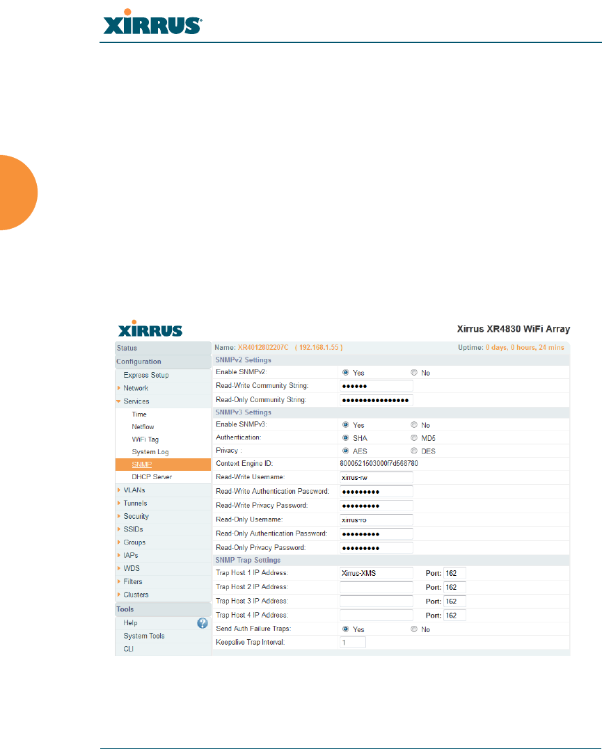
Wireless Array
194 Configuring the Wireless Array
SNMP
This window allows you to enable or disable SNMP v2 and SNMP v3 and define
the SNMP parameters. SNMP allows remote management of the Array by the
Xirrus Management System (XMS) and other SNMP management tools. SNMP v3
was designed to offer much stronger security. You may enable either SNMP
version, neither, or both.
Complete SNMP details for the Array, including trap descriptions, are found in
the Xirrus MIB, available at support.xirrus.com, in the Downloads section (login
is required to download the MIB).
NOTE: If you are managing your Arrays with XMS (the Xirrus Management System),
it is very important to make sure that your SNMP settings match those that you have
configured for XMS. XMS uses both SNMP v2 and v3, with v3 given preference.
Figure 114. SNMP

Wireless Array
Configuring the Wireless Array 195
Procedure for Configuring SNMP
SNMPv2 Settings
1. Enable SNMPv2: Choose Yes to enable SNMP v2 functionality, or choose
No to disable this feature. When used in conjunction with the Xirrus
Management System, SNMP v2 (not SNMP v3) must be enabled on each
Array to be managed with XMS. The default for this feature is Yes
(enabled).
2. SNMP Read-Write Community String: Enter the read-write community
string. The default is xirrus.
3. SNMP Read-Only Community String: Enter the read-only community
string. The default is xirrus_read_only.
SNMPv3 Settings
4. Enable SNMPv3: Choose Yes to enable SNMP v3 functionality, or choose
No to disable this feature. The default for this feature is Yes (enabled).
5. Authentication: Select the desired method for authenticating SNMPv3
packets: SHA (Secure Hash Algorithm) or MD5 (Message Digest
Algorithm 5).
6. Privacy: Select the desired method for encrypting data: DES (Data
Encryption Standard) or the stronger AES (Advanced Encryption
Standard).
7. Context Engine ID: The unique identifier for this SNMP server. We
recommend that you do not change this value. The Context Engine ID
must be set if data collection is to be done via a proxy agent. This ID helps
the proxy agent to identify the target agent from which data is to be
collected.
8. SNMP Read-Write Username: Enter the read-write user name. This
username and password allow configuration changes to be made on the
Array. The default is xirrus-rw.
9. SNMP Read-Write Authentication Password: Enter the read-write
password for authentication (i.e., logging in). The default is xirrus-rw.

Wireless Array
196 Configuring the Wireless Array
10. SNMP Read-Write Privacy Password: Enter the read-write password for
privacy (i.e., a key for encryption). The default is xirrus-rw.
11. SNMP Read-Only Username: Enter the read-only user name. This
username and password do not allow configuration changes to be made
on the Array. The default is xirrus-ro.
12. SNMP Read-Only Authentication Password: Enter the read-only
password for authentication (i.e., logging in). The default is xirrus-ro.
13. SNMP Read-Only Privacy Password: Enter the read-only password for
privacy (i.e., a key for encryption). The default is xirrus-ro.
SNMP Trap Settings
14. SNMP Trap Host IP Address: Enter the IP Address or hostname, as well
as the Port number, of an SNMP management station that is to receive
SNMP traps. You may specify up to four hosts that are to receive traps.
Note that by default, Tra p Ho st 1 sends traps to Xirrus-XMS. Thus, the
Array will automatically communicate its presence to XMS (as long as the
network is configured correctly to allow this host name to be resolved —
note that DNS is not normally case-sensitive).
For a definition of the traps sent by Xirrus Wireless Arrays, you may
download the Xirrus MIB from support.xirrus.com (login required).
Search for the string TRAP in the MIB file.
15. Send Auth Failure Traps: Choose Yes to log authentication failure traps
or No to disable this feature.
16. Keepalive Trap Interval (minutes): Traps are sent out at this interval to
indicate the presence of the Array on the network. Keepalive traps are
required for proper operation with XMS. To disable keepalive traps, set
the value to 0.
17. Click Save changes to flash if you wish to make your changes
permanent.
See Also
Services
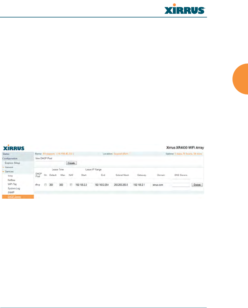
Wireless Array
Configuring the Wireless Array 197
System Log
Time Settings (NTP)
DHCP Server
This window allows you to create, enable, modify and delete DHCP (Dynamic
Host Configuration Protocol) address pools. DHCP allows the Array to provide
wireless clients with IP addresses and other networking information. The DHCP
server will not provide DHCP services to the wired side of the network. If you do
not use the DHCP server on the Array, then your wired network must be
configured to supply DHCP addresses and gateway and DNS server addresses to
wireless clients.
When you create a DHCP pool, you must define the DHCP lease time (default
and maximum), the IP address ranges (pools) that the DHCP server can assign,
and the gateway address and DNS servers to be used by clients.
Figure 115. DHCP Management
DHCP usage is determined in several windows — see SSID Management, Group
Management, and VLAN Management.
Procedure for Configuring the DHCP Server
1. New Internal DHCP Pool: Enter a name for the new DHCP pool, then
click on the Create button. The new pool ID is added to the list of
available DHCP pools.
2. On: Click this checkbox to make this pool of addresses available, or clear
it to disable the pool.

Wireless Array
198 Configuring the Wireless Array
3. Lease Time — Default: This field defines the default DHCP lease time (in
seconds). The factory default is 300 seconds, but you can change the
default at any time.
4. Lease Time — Max: Enter a value (in seconds) to define the maximum
allowable DHCP lease time. The default is 300 seconds.
5. Network Address Translation (NAT): Check this box to enable the
Network Address Translation feature.
6. Lease IP Range — Start: Enter an IP address to define the start of the IP
range that will be used by the DHCP server. The default is 192.168.1.100.
7. Lease IP Range — End: Enter an IP address to define the end of the IP
range that will be used by the DHCP server. The DHCP server will only
use IP addresses that fall between the start and end range that you define
on this page. The default is 192.168.1.200.
8. Subnet Mask: Enter the subnet mask for this IP range for the DHCP
server. The default is 255.255.255.0.
9. Gateway: If necessary, enter the IP address of the gateway.
10. Domain: Enter the DNS domain name. See “DNS Settings” on page 181.
11. DNS Servers (1 to 3): Enter the IP address of the primary DNS server,
secondary DNS server and tertiary DNS server. These DNS server
addresses will be passed to stations when they associate, along with the
assigned IP address. Note that if you leave these blank, no DNS
information is sent to the stations. DHCP will not default to sending the
DNS servers that are configured in DNS Settings. See also, “DNS
Settings” on page 181.
12. Click Save changes to flash if you wish to make your changes
permanent.
See Also
DHCP Leases
DNS Settings
Network Map
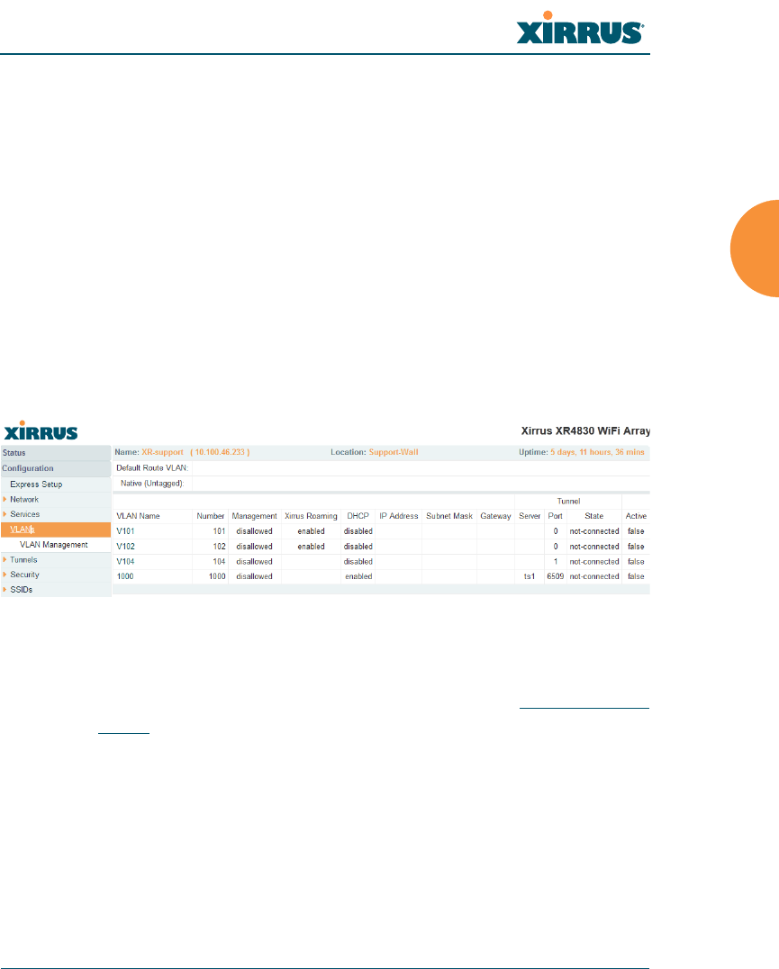
Wireless Array
Configuring the Wireless Array 199
VLANs
This is a status-only window that allows you to review the current status of
configured VLANs. VLANS are virtual LANs used to create broadcast domains.
In addition to listing all VLANs, this window shows your settings for the Default
Route VLAN and the Native (Untagged) VLAN (Step 1 page 202).
Figure 116. VLANs
Understanding Virtual Tunnels
Xirrus Arrays support Layer 2 tunneling. This allows an Array to use tunnels to
transport traffic for one or more SSID-VLAN pairs onto a single destination
network through the Layer 3 core network. Tunnels may be implemented with:
The Xirrus Tunnel Server (XTS)—see the Xirrus Tunnel Server User’s Guide.
Virtual Tunnel Server (VTS)—see below.
You should create VLAN entries on the Array for all of the VLANs in your
wired network if you wish to make traffic from those VLANs available on the
wireless network. Each tagged VLAN should be associated with a wireless
SSID (see “VLAN Management” on page 201). The Array will discard any
VLAN-tagged packets arriving on its wired ports, unless the same VLAN
has been defined on the Array. See “Undefined VLANs” on page 113.
For a discussion of implementing Voice over Wi-Fi on the Array, see the
Xirrus Voice over Wireless Application Note in the Xirrus Resource
Center.

Wireless Array
200 Configuring the Wireless Array
Virtual Tunnel Server (VTS)
Tunneling capability is provided by a Virtual Tunnel Server. You supply the server
and deploy it in your network using open-source VTun software, available from
vtun.sourceforge.net. To enable the Array to use tunneling for a VLAN, simply
enter the IP address, port and secret for the tunnel server as described in Step 11
on page 203.
VTun may be configured for a number of different tunnel types, protocols, and
encryption types. For use with Arrays, we recommend the following
configuration choices:
Tunnel Type: Ether (Ethernet tunnel)
Protocol: UDP
Encryption Type: select one of the encryption types supported by VTun
(AES and Blowfish options are available)
Keepalive: yes
VTS Client-Server Interaction
The Array is a client of the Virtual Tunnel Server. When you specify a VTS for an
active VLAN-SSID pair, the Array contacts the VTS. The server then creates a
tunnel session to the Array. VTun encapsulated packets will cross the Layer 3
network from the Array to the VTS. When packets arrive at the VTS, they will be
de-encapsulated and the resultant packets will be passed to your switch with
802.1q VLAN tags for final Layer 2 processing. The process occurs in reverse for
packets traveling in the other direction.
We recommend that you enable the VTun keep-alive option. This will send a
keep-alive packet once per second to ensure that the tunnel remains active.
Tunnels can be configured to come up on demand but this is a poor choice for
wireless, since tunnel setup can take roughly 5-20 seconds and present a problem
for authentication.
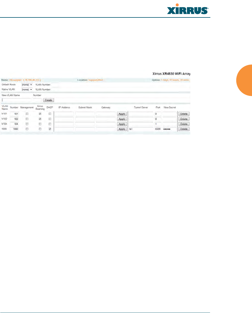
Wireless Array
Configuring the Wireless Array 201
VLAN Management
This window allows you to assign and configure VLANs. After creating a new
VLAN (added to the list of VLANs), you can modify the configuration
parameters of an existing VLAN or delete a selected VLAN. You may create up to
32 VLANs.
Figure 117. VLAN Management
The Wireless Array supports dynamic VLAN assignments specified by
RADIUS policy settings. When RADIUS sends these assignments, the
Array dynamically assigns wireless stations to VLANs as requested.
VLAN tags on traffic are passed through the Array (i.e., VLAN tags are
not stripped). Once a station has been dynamically moved to a new
VLAN, it will be shown in the Stations window as a member of the new
VLAN. (Figure 70 on page 126)
It is critical to configure all VLANs to be used on the Array, even those
that will be dynamically assigned.

Wireless Array
202 Configuring the Wireless Array
Procedure for Managing VLANs
1. Default Route: This option sets a default route from the Array. The Array
supports a default route on native and tagged interfaces. Once the default
route is configured the Array will attempt to use Address Resolution
Protocol (ARP) to find the default router. ARP finds the MAC address of a
device with a given IP address by sending out a broadcast message
requesting this information. This option allows you to choose a default
VLAN route from the pull-down list. The IP Gateway must be established
for this function to work. After changing the Default Route, you must
click Save changes to flash and then reboot.
2. Native VLAN: This option sets whether the Array management is tagged
or untagged. If you select a Native VLAN, then that VLAN will use an
untagged (Native) link. Otherwise, the Array will use 802.1Q tagging and
a specific VLAN ID with management enabled for management of the
Array.
3. New VLAN Name/Number: Enter a name and number for the new
VLAN in this field, then click on the Create button. The new VLAN is
added to the list.
4. VLAN Number: Enter a number for this VLAN (1-4094).
5. Management: Check this box to allow management over this VLAN.
6. Xirrus Roaming: Check this box to allow roaming over this VLAN.
7. DHCP: Check this box if you want the DHCP server to assign the IP
address, subnet mask and gateway address to the VLAN automatically,
otherwise you must go to the next step and assign these parameters
manually.
8. IP Address: If the DHCP option is disabled, enter a valid IP address for
this VLAN association.
9. Subnet Mask: If the DHCP option is disabled, enter the subnet mask IP
address for this VLAN association.

Wireless Array
Configuring the Wireless Array 203
10. Gateway: If the DHCP option is disabled, enter the IP gateway address
for this VLAN association.
11. Tunnel Server: If this VLAN is to be tunneled, enter the IP address or
host name of the tunnel server that will perform the tunneling. For more
information on virtual tunnels, please see “Understanding Virtual
Tunnels” on page 199.
12. Port: If this VLAN is to be tunneled, enter the port number of the tunnel
server.
13. New Secret: Enter the password expected by the tunnel server.
14. Delete: To delete the selected VLAN, simply click the Delete button to
remove the VLAN from the list.
15. Click Save changes to flash if you wish to make your changes
permanent.
See Also
VLAN Statistics
VLANs
Tunnels
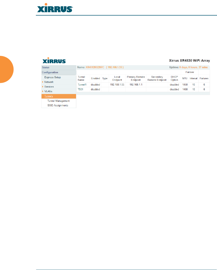
Wireless Array
204 Configuring the Wireless Array
Tunnels
This read-only window allows you to review the tunnels that have been defined
on the Array. It lists all tunnels and their settings, including the type of
authentication and the local and remote endpoints for each tunnel.
Figure 118. Tunnel Summary
About Xirrus Tunnels
Xirrus Arrays offer GRE (Generic Routing Encapsulation) tunneling with VLAN
support. This allows an Array to use tunnels to bridge Layer 2 traffic for one or
more SSID-VLAN pairs onto a single destination network through the Layer 3
network. GRE tunneling is quite flexible, and can encapsulate many network
layer protocols. As a result, it can support a variety of applications. For example, a
Wi-Fi hotspot can allow guest logins and use the tunnel to give guests direct
access to the Internet, without allowing access to the local network. In a small
office, you may define a tunnel to connect users to the corporate office network.
Tunnels may also used when providing cellular offload capability.
Tunnels may be implemented with:
The Xirrus Tunnel Server (XTS)—see the Xirrus Tunnel Server User’s Guide.
VTS —see “Virtual Tunnel Server (VTS)” on page 200.
To create a tunnel, you specify the Local Endpoint, which should be one of the
Array’s wired ports, and the Primary Remote Endpoint. A Secondary Remote
Endpoint may also be specified in case of a failure at the first endpoint. Traffic for
a VLAN-SSID pair is sent in GRE encapsulated packets across the Layer 3
network from the Array to the remote endpoint. When packets arrive, the
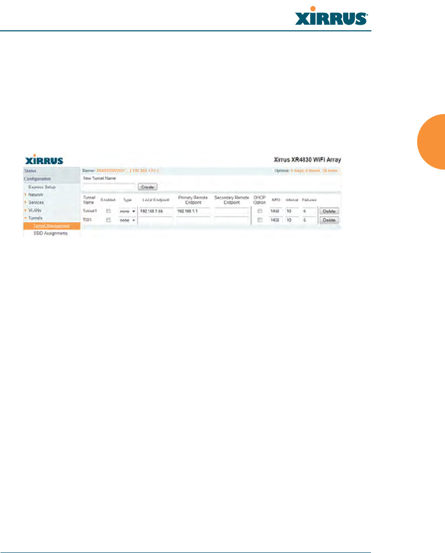
Wireless Array
Configuring the Wireless Array 205
encapsulation is stripped and the resultant packets are passed to your switch with
802.1q VLAN tags for final Layer 2 processing. The process occurs in reverse for
packets traveling in the other direction. One tunnel is able to transport up to 16
VLANs.
Tunnel Management
This window allows you to create tunnels.
Figure 119. Tunnel Management
Procedure for Managing Tunnels
1. New Tunnel Name: Enter a name for the new tunnel in this field, then
click on the Create button. The new tunnel is added to the list.
2. Enabled: The new tunnel is created in the disabled state. Click this
checkbox to enable it.
3. Type: Enter the type of tunnel, none or gre.
4. Local Endpoint: Enter the IP address of the Array Gigabit or 10 Gigabit
port where the tunnel is to begin.
5. Primary Remote Endpoint: Enter the IP address of the remote endpoint
of the tunnel.
6. Secondary Remote Endpoint: This provides a failover capability. If the
primary tunnel fails, traffic is switched over to the secondary tunnel.
Enter the IP address of the remote endpoint of the secondary tunnel.
7. DHCP Option: Check this box if you want the DHCP server to assign the
IP address, subnet mask and gateway address when a station makes a
DHCP request.
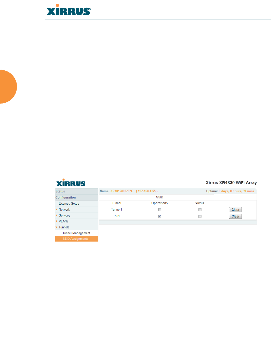
Wireless Array
206 Configuring the Wireless Array
8. MTU: Set maximum transmission unit (MTU) size.
9. Interval: The tunnel mechanism will ping the current remote endpoint
periodically to ensure that it is still reachable. Enter the ping interval (in
seconds).
10. Failures: Enter the number of consecutive ping failures that will cause the
Array to consider the tunnel to be down.
11. Click Save changes to flash if you wish to make your changes
permanent.
12. Proceed to SSID Assignments to define the SSIDs (and associated
VLANs) for which each tunnel will bridge data. You may create up to 16
tunnels. Each will need an SSID/VLAN pair assigned to it so that it can
function properly.
SSID Assignments
This window allows you to select the SSIDs to be bridged by each tunnel.
Figure 120. Tunnel SSID Assignments
Procedure for Assigning SSIDs
This window lists the tunnels and SSIDs that you have defined. SSIDs to be
tunnelled should be associated with a VLAN (see “SSID Management” on
page 249).

Wireless Array
Configuring the Wireless Array 207
1. For each tunnel, select the SSIDs that are to be bridged to the remote
endpoint. Clear the checkbox for any SSID that you no longer wish to
include in the tunnel.
2. Click Save changes to flash if you wish to make your changes
permanent.
See Also
Tunnels
VLANs
SSIDs
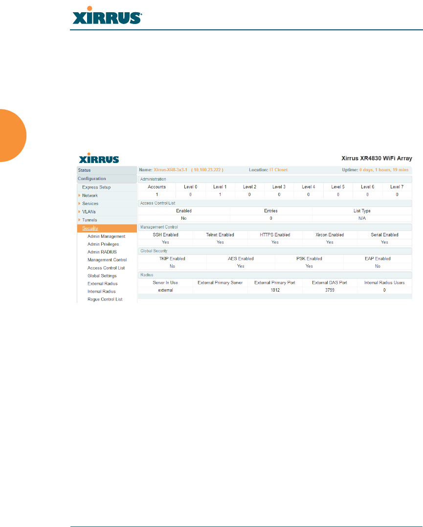
Wireless Array
208 Configuring the Wireless Array
Security
This status- only window allows you to review the Array’s security parameters. It
includes the assigned network administration accounts, Access Control List
(ACL) values, management settings, encryption and authentication protocol
settings, and RADIUS configuration settings. There are no configuration options
available in this window, but if you are experiencing issues with security, you
may want to print this window for your records.
Figure 121. Security
For additional information about wireless network security, refer to:
“Security Planning” on page 46
“Understanding Security” on page 209
The Security section of “Frequently Asked Questions” on page 452
For information about secure use of the WMI, refer to:
“Certificates and Connecting Securely to the WMI” on page 212
“Using the Array’s Default Certificate” on page 212
“Using an External Certificate Authority” on page 213
“About Creating Admin Accounts on the RADIUS Server” on page 218
“About Creating User Accounts on the RADIUS Server” on page 234

Wireless Array
Configuring the Wireless Array 209
Security settings are configured with the following windows:
“Admin Management” on page 214
“Admin Privileges” on page 216
“Admin RADIUS” on page 218
“Management Control” on page 221
“Access Control List” on page 227
“Global Settings” on page 230
“External Radius” on page 234
“Internal Radius” on page 238
“Rogue Control List” on page 240
Understanding Security
The Xirrus Wireless Array incorporates many configurable security features.
After initially installing an Array, always change the default administrator
password (the default is admin), and choose a strong replacement password
(containing letters, numbers and special characters). When appropriate, issue
read-only administrator accounts.
Other security considerations include:
SSH versus Telnet: Be aware that Telnet is not secure over network
connections and should be used only with a direct serial port connection.
When connecting to the unit’s Command Line Interface over a network
connection, you must use a Secure SHell version 2 (SSH-2) utility. SSH-2
provides stronger security than SSH-1. The most commonly used
freeware providing SSH tools is PuTTY.
Configuration auditing: The optional Xirrus Management System (XMS)
offers powerful management features for small or large Xirrus wireless
deployments, and can audit your configuration settings automatically. In
addition, using the XMS eliminates the need for an FTP server.
Choosing an encryption method: Wireless data encryption prevents
eavesdropping on data being transmitted or received over the airwaves.

Wireless Array
210 Configuring the Wireless Array
The Array allows you to establish the following data encryption
configuration options:
•Open — this option offers no data encryption and is not
recommended, though you might choose this option if clients are
required to use a VPN connection through a secure SSH utility,
like PuTTy.
•WEP (Wired Equivalent Privacy) — this option provides minimal
protection (though much better than using an open network). An
early standard for wireless data encryption and supported by all
Wi-Fi certified equipment, WEP is vulnerable to hacking and is
therefore not recommended for use by Enterprise networks.
•WPA (Wi-Fi Protected Access) and WPA2 — these are much
stronger encryption modes than WEP, using TKIP (Temporal Key
Integrity Protocol) or AES (Advanced Encryption Standard) to
encrypt data.
WPA solves security issues with WEP. It also allows you to
establish encryption keys on a per-user-basis, with key rotation
for added security. In addition, TKIP provides Message Integrity
Check (MIC) functionality and prevents active attacks on the
wireless network.
AES is the strongest encryption standard and is used by
government agencies; however, old legacy hardware may not be
capable of supporting the AES mode (it probably won’t work on
older wireless clients). Because AES is the strongest encryption
standard currently available, WPA2 with AES is highly
recommended for Enterprise networks.
Any of the above encryption methods can be used and an Array can
support multiple encryption methods simultaneously, but only one
method may be selected per SSID (except that selecting WPA-Both allows
WPA and WPA2 to be used at the same time on the same SSID).
Otherwise, if multiple security methods are needed, you must define
multiple SSIDs.

Wireless Array
Configuring the Wireless Array 211
The encryption mode (WEP, WPA, etc.) is selected in the SSIDs >SSID
Management window (see “SSID Management” on page 249).
The encryption standard used with WPA or WPA2 (AES or TKIP) is
selected in the Security>Global Settings window under WPA Settings
(see “Global Settings” on page 230).
Choosing an authentication method: User authentication ensures that
users are who they say they are. For this purpose, the Array allows you to
choose between the following user authentication methods:
•Pre-Shared Key — users must manually enter a key (passphrase)
on the client side of the wireless network that matches the key
stored by the administrator in the Array.
This method should be used only for smaller networks when a
RADIUS server is unavailable. If PSK must be used, choose a
strong passphrase containing between 8 and 63 characters (20 is
preferred). Always use a combination of letters, numbers and
special characters. Never use English words separated by spaces.
•RADIUS 802.1x with EAP — 802.1x uses a RADIUS server to
authenticate large numbers of clients, and can handle different
EAP (Extensible Authentication Protocol) authentication
methods, including EAP-TLS, EAP-TTLS, EAP-PEAP, and LEAP-
Passthrough. The RADIUS server can be internal (provided by
the Wireless Array) or external. An external RADIUS server
offers more functionality and security, and is recommended for
large deployments. When using this method, user names and
passwords must be entered into the RADIUS server for user
authentication.
•MAC Address ACLs (Access Control Lists) — MAC address
ACLs provide a list of client adapter MAC addresses that are
allowed or denied access to the wireless network. Access Control
Lists work well when there are a limited number of users — in
this case, enter the MAC address of each user in the Allow list. In
the event of a lost or stolen MAC adapter, enter the affected MAC
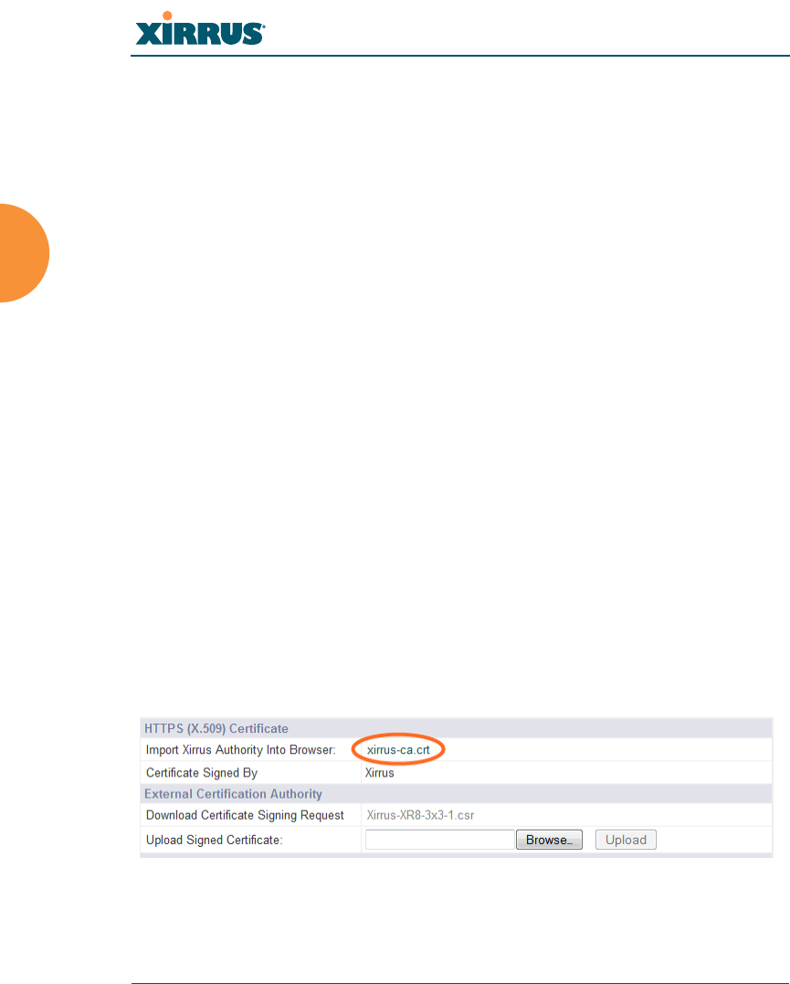
Wireless Array
212 Configuring the Wireless Array
address in the Deny list. The Wireless Array will accept up to
1,000 ACL entries.
Certificates and Connecting Securely to the WMI
When you point your browser to the Array to connect to the WMI, the Array
presents an X.509 security certificate to the browser to establish a secure channel.
One significant piece of information in the certificate is the Array’s host name.
This ties the certificate to a particular Array and ensures the client that it is
connecting to that host.
Certificate Authorities (CAs) are entities that digitally sign certificates, using their
own certificates (for example, VeriSign is a well-known CA). When the Array
presents its certificate to the client’s browser, the browser looks up the CA that
signed the certificate to decide whether to trust it. Browsers ship with a small set
of trusted CAs already installed. If the browser trusts the certificate’s CA, it
checks to ensure the host name (and IP address) match those on the certificate. If
any of these checks fail, you get a security warning when connecting to the WMI.
The Array ships with a default certificate that is signed by the Xirrus CA. You
may choose to use this certificate, or to use a certificate issued by the CA of your
choice, as described in the following sections:
Using the Array’s Default Certificate
Using an External Certificate Authority
Using the Array’s Default Certificate
Figure 122. Import Xirrus Certificate Authority

Wireless Array
Configuring the Wireless Array 213
The Array’s certificate is signed by a Xirrus CA that is customized for your Array
and its current host name. By default, browsers will not trust the Array’s
certificate. You may import the Xirrus certificate to instruct the browser to trust
the Xirrus CA on all future connections to Arrays. The certificate for the Xirrus
CA is available on the Array, so that you can import it into your browser’s cache
of trusted CAs (right alongside VeriSign, for example). On the Management
Control window of the WMI you will see the xirrus-ca.crt file. (Figure 122)
By clicking and opening this file, you can follow your browser’s instructions and
import the Xirrus CA into your CA cache (see page 225 for more information).
This instructs your browser to trust any of the certificates signed by the Xirrus
CA, so that when you connect to any of our Arrays you should no longer see the
warning about an untrusted site. Note however, that this only works if you use
the host name when connecting to the Array. If you use the IP address to connect,
you get a lesser warning saying that the certificate was only meant for ‘hostname’.
Since an Array’s certificate is based on the Array’s host name, any time you
change the host name the Array’s CA will regenerate and sign a new certificate.
This happens automatically the next time you reboot after changing the host
name. If you have already installed the Xirrus CA on a browser, this new Array
certificate should automatically be trusted.
When you install the Xirrus CA in your browser, it will trust a certificate signed
by any Xirrus Array, as long as you connect using the Array’s host name.
Using an External Certificate Authority
If you prefer, you may install a certificate on your Array signed by an outside CA.
Why use a certificate from an external CA? The Array’s certificate is used for
security when stations attempt to associate to an SSID that has Web Page Redirect
enabled. In this case, it is preferable for the Array to present a certificate from an
external CA that is likely to be trusted by most browsers. When a WPR login page
is presented, the user will not see a security error if the Array’s certificate was
obtained from an external CA that is already trusted by the user’s browser.
WMI provides options for creating a Certificate Signing Request that you can
send to an external CA, and for uploading the signed certificate to the Array after
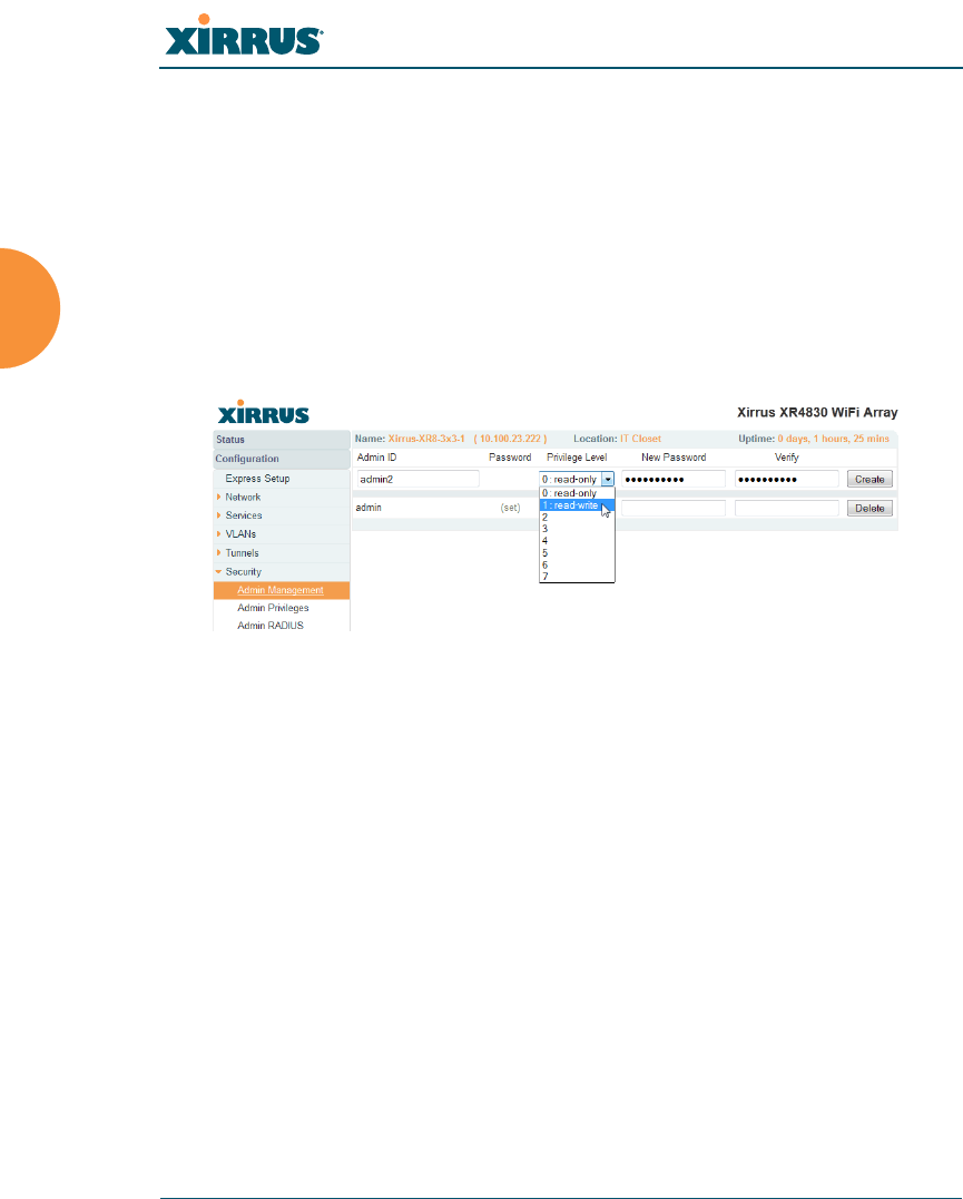
Wireless Array
214 Configuring the Wireless Array
you obtain it from the CA. This certificate will be tied to the Array’s host name
and private key. See “External Certification Authority” on page 226 for more
details.
Admin Management
This window allows you to manage network administrator accounts (create,
modify and delete). It also allows you to limit account access to a read only status.
When finished, click on the Save changes to flash button if you wish to make
your changes permanent.
Figure 123. Admin Management
Procedure for Creating or Modifying Network Administrator Accounts
1. Admin ID: Enter the login name for a new network administrator ID.
The length of the ID must be between 5 and 50 characters, inclusive.
2. Read/Write: Choose 1:read-write if you want to give this administrator
ID full read/write privileges, or choose 0:read-only to restrict this user to
read only status. In the read only mode, administrators cannot save
changes to configurations. Or you may select one of your custom-defined
privilege levels (see “Admin Privileges” on page 216).
3. New Password: Enter a password for this ID. The length of the password
must be between 5 and 50 characters, inclusive.
4. Verify: Re-enter the password in this field to verify that you typed the
password correctly. If you do not re-enter the correct password, an error
message is displayed).

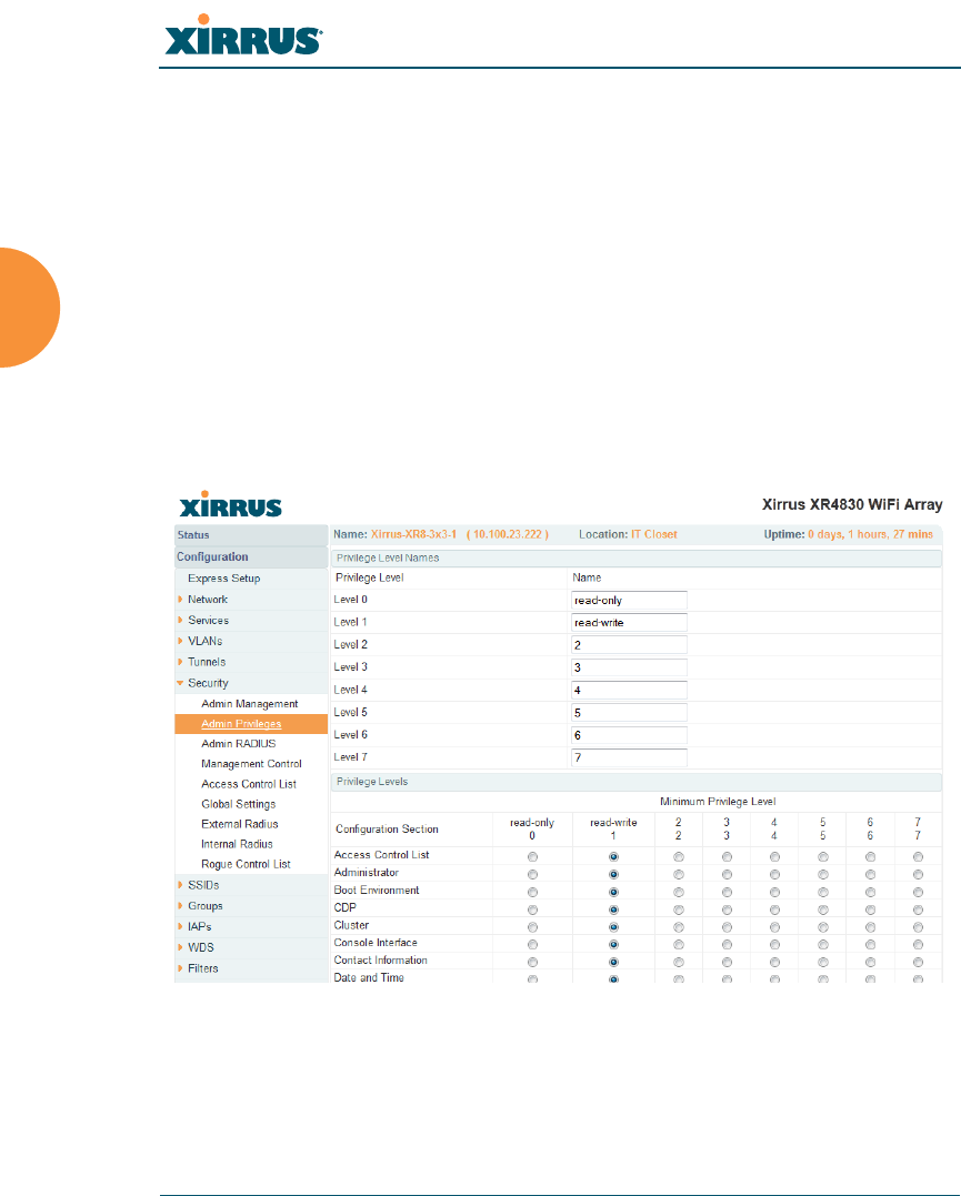
Wireless Array
216 Configuring the Wireless Array
Admin Privileges
This window provides a detailed level of control over the privileges of Array
administrators. Administrators may be assigned one of eight Privilege Levels.
You may define the privilege level of each major feature (Configuration Section)
that may be configured on the Array. For example, say that you set the privilege
level to 4 for Reboot Array, Security, Radius Server, and SNMP, and you leave all
other configuration sections at the default privilege level of 1. In this case, any
administrator with a privilege level of 4 or higher may perform any operation on
the Array, while an administrator with a privilege level lower than 4 but at least 1
may perform any operation except those whose level was set to 4. An error
message will be displayed if an operation is attempted without a sufficient
privilege level.
Figure 124. Admin Privileges
Privilege level 0 is read-only. As a minimum, all administrators have permission
for read access to all areas of Array configuration. Higher privilege levels may be
used to define additional privileges for specific configuration sections.

Wireless Array
Configuring the Wireless Array 217
If you are using an Admin RADIUS server to define administrator accounts,
please see “RADIUS Vendor Specific Attribute (VSA) for Xirrus” on page 463 to
set the privilege level for each administrator.
Procedure for Configuring Admin Privileges
1. Privilege Level Names (optional): You may assign a Name to each
Privilege Level. The name may be used to describe the access granted by
this level. By default, levels 0 and 1 are named read-only and read-write,
respectively, and levels 2 through 7 have the same name as their level
number.
2. Privilege Levels: Use this section to assign a Minimum Privilege Level
to selected Configuration Sections as desired. By default, all sections are
assigned level 1. When you select a higher privilege level for a
configuration section, then only administrators who have at least that
privilege level will be able to make configuration changes to that section.
3. You may click ^ at the bottom of any row to toggle the values in the entire
column to either on or off.
4. Click Save changes to flash if you wish to make your changes
permanent.
See Also
External Radius
Groups
Admin Management
Admin RADIUS
Security

Wireless Array
218 Configuring the Wireless Array
Admin RADIUS
This window allows you to set up authentication of network administrators via
RADIUS. Using RADIUS to control administrator accounts for logging in to
Arrays has these benefits:
Centralized control of administrator accounts.
Less effort — you don't have to set up user names and passwords on each
Array; just enter them once on the RADIUS server and then all of the
Arrays can pull from the RADIUS server.
Enforced policies — you may set password rules (e.g., passwords must
contain at least one number and be at least 12 characters in length), and
you may set expiration times for passwords.
Admin RADIUS settings override any local administrator accounts configured on
the Admin Management window. If you have Admin RADIUS enabled, all
administrator authentication is done via the configured RADIUS servers. The
only exception to this is when you are connected via the Console port (using CLI).
If you are using the Console port, the Array will authenticate administrators
using accounts configured on the Admin Management window first, and then use
the RADIUS servers. This provides a safety net to be ensure that you are not
completely locked out of an Array if the RADIUS server is down.
About Creating Admin Accounts on the RADIUS Server
Permissions for RADIUS administrator accounts are controlled by the RADIUS
Xirrus-Admin-Role attribute. This is a Vendor Specific Attribute (VSA). To define
the privileges permitted to an administrator account, set the value of its Xirrus-
Admin-Role attribute to the desired Privilege Level Name string, as defined in
“Admin Privileges” on page 216. For more information about the RADIUS VSAs
used by Xirrus, see “RADIUS Vendor Specific Attribute (VSA) for Xirrus” on
page 463.
When configuring administrator accounts on the RADIUS server, you must
observe the same restrictions for length and legal characters as when creating
these accounts on the Array using the Admin Management window: the user
name and password must be between 5 and 50 characters, inclusive.
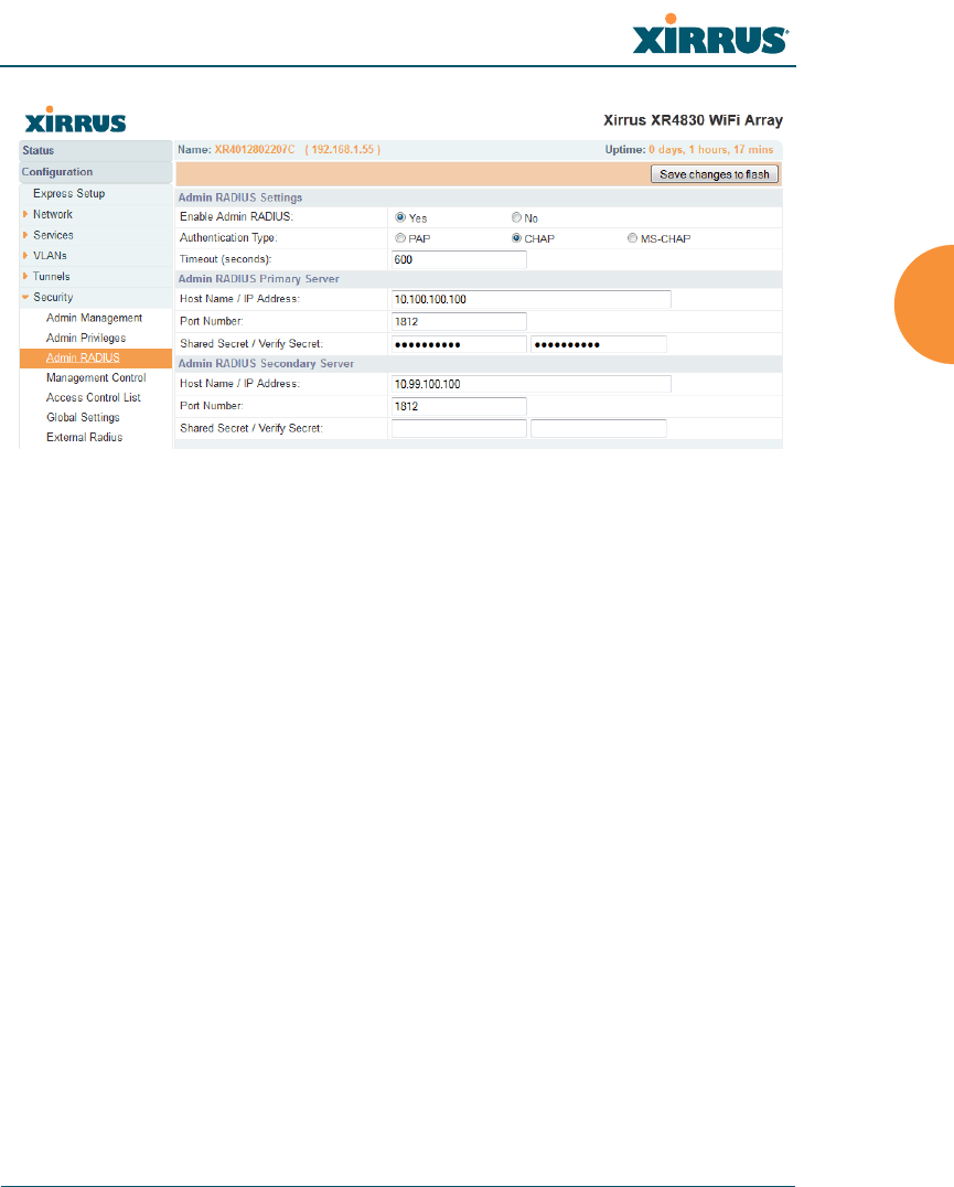
Wireless Array
Configuring the Wireless Array 219
Figure 125. Admin RADIUS
Procedure for Configuring Admin RADIUS
Use this window to enable/disable administrator authentication via RADIUS,
and to set up primary and secondary servers to use for authentication of
administrators attempting to log in to the Array.
1. Admin RADIUS Settings:
a. Enable Admin RADIUS: Click Yes to enable the use of RADIUS to
authenticate administrators logging in to the Array. You will need to
specify the RADIUS server(s) to be used.
b. Authentication Type: Select the protocol used for authentication of
administrators, CHAP or PAP (the default).
•PAP (Password Authentication Protocol), is a simple protocol.
PAP transmits ASCII passwords over the network “in the clear”
(unencrypted) and is therefore considered insecure.
•CHAP (Challenge-Handshake Authentication Protocol) is a more
secure protocol. The login request is sent using a one-way hash
function.

Wireless Array
220 Configuring the Wireless Array
c. Timeout (seconds): Define the maximum idle time (in seconds)
before the RADIUS server’s session times out. The default is 600
seconds.
2. Admin RADIUS Primary Server: This is the RADIUS server that you
intend to use as your primary server.
a. Host Name / IP Address: Enter the IP address or domain name of this
external RADIUS server.
b. Port Number: Enter the port number of this RADIUS server. The
default is 1812.
c. Shared Secret / Verify Secret: Enter the shared secret that this
RADIUS server will be using, then re-enter the shared secret to verify
that you typed it correctly.
3. Admin RADIUS Secondary Server (optional): If desired, enter an
alternative external RADIUS server. If the primary RADIUS server
becomes unreachable, the Array will “failover” to the secondary RADIUS
server (defined here).
a. Host Name / IP Address: Enter the IP address or domain name of this
RADIUS server.
b. Port Number: Enter the port number of this RADIUS server.
The default is 1812.
c. Shared Secret / Verify Secret: Enter the shared secret that this
RADIUS server will be using, then re-enter the shared secret to verify
that you typed it correctly.
The shared secret that you define must match the secret used by the
RADIUS server.
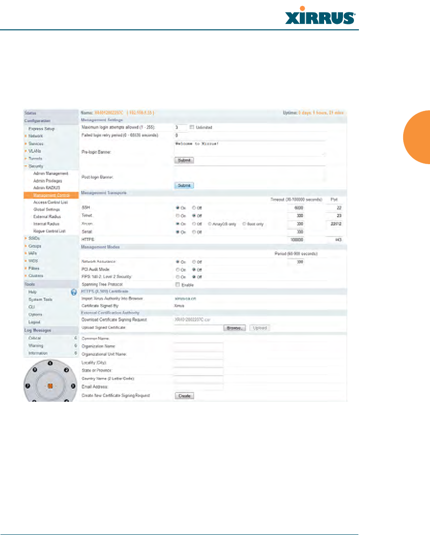
Wireless Array
Configuring the Wireless Array 221
Management Control
This window allows you to enable or disable the Array management interfaces
and set their inactivity time-outs. The supported range is 300 (default) to 100,000
seconds.
Figure 126. Management Control
Procedure for Configuring Management Control
1. Management Settings:
a. Maximum login attempts allowed (1-255): After this number of
consecutive failing administrator login attempts via ssh or telnet, the
Failed login retry period is enforced. The default is 3.
Wireless Array
222 Configuring the Wireless Array
b. Failed login retry period (0-65535 seconds): After the maximum
number (defined above) of consecutive failing administrator login
attempts via ssh or telnet, the administrator’s IP address is denied
access to the array for the specified period of time (in seconds). The
default is 0.
c. Pre-login Banner: Text that you enter here will be displayed above
the WMI login prompt. (Figure 127)
Figure 127. Pre-login Banner
d. Post-login Banner: Text that you enter here will be displayed in a
message box after a user logs in to the WMI.
2. SSH
a. On/Off: Choose On to enable management of the Array over a Secure
Shell (SSH-2) connection, or Off to disable this feature. Be aware that
only SSH-2 connections are supported by the Array. SSH clients used
for connecting to the Array must be configured to use SSH-2.
b. Connection Timeout 30-100000 (Seconds): Enter a value in this field
to define the timeout (in seconds) before your SSH connection is
disconnected. The value you enter here must be between 30 seconds
and 100,000 seconds.
c. Port: Enter a value in this field to define the port used by SSH.
The default port is 22.

Wireless Array
Configuring the Wireless Array 223
3. Telnet:
a. On/Off: Choose On to enable Array management over a Telnet
connection, or Off to disable this feature. SSH offers a more secure
connection than Telnet, and is recommended over Telnet.
b. Connection Timeout 30-100000 (Seconds): Enter a value in this field
to define the timeout (in seconds) before your Telnet connection is
disconnected. The value you enter here must be between 30 seconds
and 100,000 seconds.
c. Port: Enter a value in this field to define the port used by Telnet.
The default port is 23.
4. Xircon
The Xircon utility is not used with XN Arrays. For those Arrays, this
setting should always be turned Off.
The Xircon utility connects to Xirrus Arrays that are not reachable via the
normal access methods (such as SSH or WMI) and that do not have a
physical console port (XR-1000 models), or whose console port is not
accessible. Please see “Securing Low Level Access to the Array” on
page 78 for more information about Xircon. You can enable or disable
Xircon access to the Array as instructed below.
a. On/Off: Choose On to enable Xircon access to the Array at the
ArrayOS (CLI) and Xirrus Boot Loader (XBL) levels, or Off to disable
access at both levels. On XR-1000 Array models only, Xircon access is
On by default. On all other Array models, Xircon access is Off by
default.
b. ArrayOS only: Choose this radio button to enable Xircon access at the
ArrayOS level only (i.e., Xircon can access CLI only). Access to the
Array at the Xirrus Boot Loader (XBL) level is disabled.
!Warning: If you disable Xircon access completely on XR-1000 models, you
must ensure that you do not lose track of the username and password to log in
to CLI/WMI! There is no way to recover from a lost password, other than
returning the Array to Xirrus.

Wireless Array
224 Configuring the Wireless Array
c. Boot only: Choose this radio button to enable Xircon access at the
Xirrus Boot Loader (XBL) level only. ArrayOS level (CLI) access to the
Array is disabled.
d. Connection Timeout 30-100000 (Seconds): Enter a value in this field
to define the timeout (in seconds) before your Xircon connection is
disconnected. The value you enter here must be between 30 seconds
and 100,000 seconds.
e. Port: Enter a value in this field to define the port used by Xircon.
The default port is 22612.
5. Serial
a. On/Off: Choose On to enable management of the Array via a serial
connection, or choose Off to disable this feature.
b. Connection Timeout 30-100000 (Seconds): Enter a value in this field
to define the timeout (in seconds) before your serial connection is
disconnected. The value you enter here must be between 30 seconds
and 100,000 seconds.
6. HTTPS
a. Connection Timeout 30-100000 (Seconds): Enter a value in this field
to define the timeout (in seconds) before your HTTPS connection is
disconnected. The value you enter here must be between 30 seconds
and 100,000 seconds. Management via HTTPS (i.e., the Web
Management Interface) cannot be disabled on this window. To
disable management over HTTPS, you must use the Command Line
Interface.
b. Port: Enter a value in this field to define the port used by SSH.
The default port is 443.

Wireless Array
Configuring the Wireless Array 225
7. Management Modes
a. Network Assurance: Click the On button to enable this mode.
Network assurance checks network connectivity to each server that
you configure, such as the NTP server, RADIUS servers, SNMP trap
hosts, etc. By proactively identifying network resources that are
unavailable, the network manager can be alerted of problems
potentially before end-users notice an issue. The distributed
intelligence of Arrays provides this monitoring at multiple points
across the network, adding to the ability to isolate the problem and
expedite the resolution
Connectivity is checked when you configure a server. If a newly
configured server is unreachable, you will be notified directly and a
Syslog entry is created. Configured servers are checked once per
Period which by default is 300 seconds (five minutes). Servers are
checked regardless of whether they are configured as IP addresses or
host names.
If a server becomes unreachable, a Syslog message is generated.
When the server again becomes reachable, another Syslog message is
generated.
To view the status of all configured servers checked by this feature,
please see “Network Assurance” on page 112.
8. HTTPS (X.509) Certificate
a. Import Xirrus Authority into Browser: This feature imports the
Xirrus Certificate Authority (CA) into your browser (for a discussion,
please see “Certificates and Connecting Securely to the WMI” on
page 212). Click the link (xirrus-ca.crt), and then click Open to view
or install the current Xirrus CA certificate. Click Install Certificate to
start your browser’s Certificate Install Wizard. We recommend that
you use this process to install Xirrus as a root authority in your
browser.
When you assign a Host Name to your Array using the Express
Setup window, then the next time you reboot the Array it

Wireless Array
226 Configuring the Wireless Array
automatically creates a security certificate for that host name. That
certificate uses Xirrus as the signing authority. Thus, in order to avoid
having certificate errors on your browser when using WMI:
•You must have assigned a host name to the Array and rebooted at
some time after that.
•Use Import Xirrus Authority into Browser
•Access WMI by using the host name of the Array rather than its
IP address.
b. HTTPS (X.509) Certificate Signed By: This read-only field shows the
signing authority for the current certificate.
9. External Certification Authority
This Step and Step 10 allow you to obtain a certificate from an external
authority and install it on an Array. “Using an External Certificate
Authority” on page 213 discusses reasons for using an external CA.
For example, to obtain and install a certificate from VeriSign on the Array,
follow these steps:
•If you don’t already have the certificate from the external (non-
Xirrus) Certificate Authority, see Step 10 to create a request for a
certificate.
•Use Step 9a to review the request and copy its text to send to
Ver iS ign.
•When you receive the new certificate from VeriSign, upload it to the
Array using Step 9b.
External Certification Authority has the following fields:
a. Download Certificate Signing Request: After creating a certificate
signing request (.csr file — Step 10), click the View button to review it.
If it is satisfactory, click the name of the .csr file to display the text of
the request. You can then copy this text and use it as required by the
CA. You may also click on the filename of the .csr file to download it
to your local computer.

Wireless Array
Configuring the Wireless Array 227
b. Upload Signed Certificate: To use a custom certificate signed by an
authority other than Xirrus, use the Browse button to locate the
certificate file, then click Upload to copy it to the Array. The Array’s
web server will be restarted and will pick up the new certificate. This
will terminate any current web sessions, and you will need to
reconnect and re-login to the Array.
10. To create a Certificate Signing Request
a. Fill in the fields in this section: Common Name, Organization Name,
Organizational Unit Name, Locality (City), State or Province,
Country Name, and Email Address. Spaces may be used in any of
the fields, except for Common Name, Country Name, or Email
Address. Click the Create button to create the certificate signing
request. See Step 9 above to use this request.
11. Click Save changes to flash if you wish to make your changes
permanent.
See Also
Network Interfaces - to enable/disable management over an Ethernet interface
Global Settings (IAP) - to enable/disable management over IAPs
Admin Management
External Radius
Global Settings (IAP)
Internal Radius
Access Control List
Security
Access Control List
This window allows you to enable or disable the use of the global Access Control
List (ACL), which controls whether a station with a particular MAC address may
associate to the Array. You may create station access control list entries and delete
existing entries, and control the type of list.
There is only one global ACL, and you may select whether its type is an Allow
List or a Deny List, or whether use of the list is disabled.
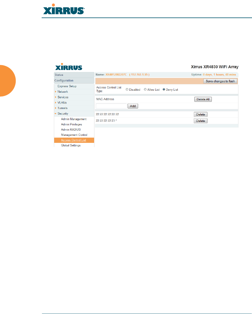
Wireless Array
228 Configuring the Wireless Array
There is also a per-SSID ACL (see “Per-SSID Access Control List” on page 262). If
the same MAC address is listed in both the global ACL and in an SSID’s ACL, and
if either ACL would deny that station access to that SSID, then access will be
denied.
Figure 128. Access Control List
Procedure for Configuring Access Control Lists
1. Access Control List Type: Select Disabled to disable use of the Access
Control List, or select the ACL type — either Allow List or Deny List.
•Allow List: Only allows the listed MAC addresses to associate to
the Array. All others are denied.
•Deny List: Denies the listed MAC addresses permission to
associate to the Array. All others are allowed.
2. MAC Address: If you want to add a MAC address to the ACL, enter the
new MAC address here, then click on the Add button. The MAC address
is added to the ACL. You may use a wildcard (*) for one or more digits to
match a range of addresses. You may create up to 1000 entries.
In addition to these lists, other authentication methods (for
example, RADIUS) are still enforced for users.

Wireless Array
Configuring the Wireless Array 229
3. Delete: You can delete selected MAC addresses from this list by clicking
their Delete buttons.
4. Click Save changes to flash if you wish to make your changes
permanent.
See Also
External Radius
Global Settings (IAP)
Internal Radius
Management Control
Security
Station Status Windows (list of stations that have been detected by the Array)
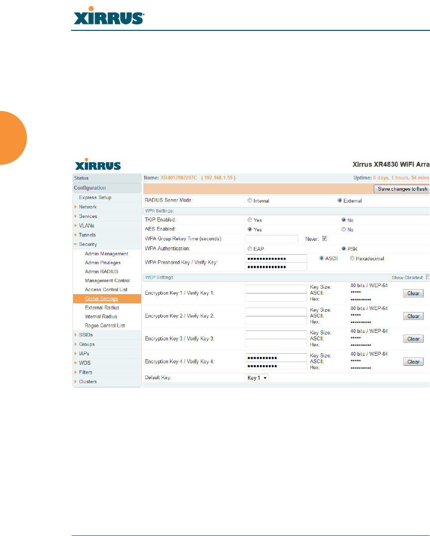
Wireless Array
230 Configuring the Wireless Array
Global Settings
This window allows you to establish the security parameters for your wireless
network, including WEP, WPA, WPA2 and RADIUS authentication. When
finished, click Save changes to flash if you wish to make your changes
permanent.
For additional information about wireless network security, refer to “Security
Planning” on page 46 and “Understanding Security” on page 209.
Figure 129. Global Settings (Security)

Wireless Array
Configuring the Wireless Array 231
Procedure for Configuring Network Security
1. RADIUS Server Mode: Choose the RADIUS server mode you want to
use, either Internal or External. Parameters for these modes are
configured in “External Radius” on page 234 and “Internal Radius” on
page 238.
WPA Settings
These settings are used if the WPA or WPA2 encryption type is selected on the
SSIDs >SSID Management window or the Express Setup window (on this
window, encryption type is set in the SSID Settings: Wireless Security field).
2. TKIP Enabled: Choose Yes to enable TKIP (Temporal Key Integrity
Protocol), or choose No to disable TKIP.
3. AES Enabled: Choose Yes to enable AES (Advanced Encryption
Standard), or choose No to disable AES. If both AES and TKIP are
enabled, the station determines which will be used.
4. WPA Group Rekey Time (seconds): Enter a value to specify the group
rekey time (in seconds). The default is Never.
5. WPA Preshared Key / Verify Key: If you enabled PSK, enter a passphrase
here, then re-enter the passphrase to verify that you typed it correctly.
TKIP encryption does not support high throughput rates (see Improved
MAC Throughput), per the IEEE 802.11n specification.
TKIP should never be used for WDS links on XR or XN Arrays.

Wireless Array
232 Configuring the Wireless Array
WEP Settings
These settings are used if the WEP encryption type is selected on the SSIDs >
SSID Management window or the Express Setup window (on this window,
encryption type is set in the SSID Settings: Wireless Security field).
Click the Show Cleartext button to make the text that you type in to the Key
fields visible.
6. Encryption Key 1 / Verify Key 1:
Key Size: Key length is automatically computed based on the Encryption
Key that you enter
•5 ASCII characters (10 hex) for 40 bits (WEP-64)
•13 ASCII characters for (26 hex) 104 bits (WEP-128)
Encryption Key 1 / Verify Key 1: Enter an encryption key in ASCII or
hexadecimal. The ASCII and translated hexadecimal values will appear
to the right if you selected the Show Cleartext button.
Re-enter the key to verify that you typed it correctly. You may include
special ASCII characters, except for the double quote symbol (“).
7. Encryption Key 2 to 4/ Verify Key 2 to 4/ Key Mode/Length (optional): If
desired, enter up to four encryption keys, in the same way that you
entered the first key.
8. Default Key: Choose which key you want to assign as the default key.
Make your selection from the pull-down list.
WEP encryption does not support high throughput rates or features like
frame aggregation or block acknowledgements (see Improved MAC
Throughput), per the IEEE 802.11n specification.
WEP should never be used for WDS links on Arrays.

Wireless Array
Configuring the Wireless Array 233
9. Click Save changes to flash if you wish to make your changes
permanent.
See Also
Admin Management
External Radius
Internal Radius
Access Control List
Management Control
Security
Security Planning
SSID Management
After configuring network security, the configuration must be
applied to an SSID for the new functionality to take effect.
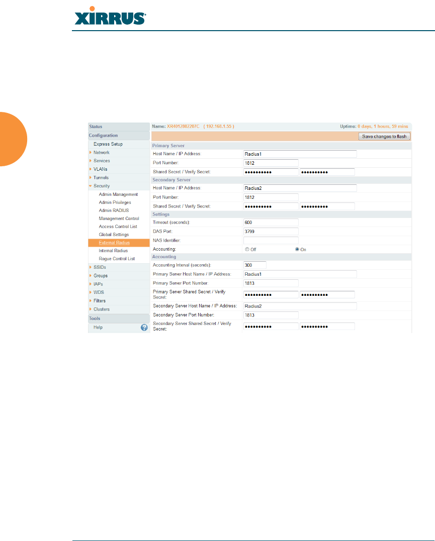
Wireless Array
234 Configuring the Wireless Array
External Radius
This window allows you to define the parameters of an external RADIUS server
for user authentication. To set up an external RADIUS server, you must choose
External as the RADIUS server mode in Global Settings. Refer to “Global
Settings” on page 230.
Figure 130. External RADIUS Server
If you want to include user group membership in the RADIUS account
information for users, see “Understanding Groups” on page 264. User groups
allow you to easily apply a uniform configuration to a user on the Array.
About Creating User Accounts on the RADIUS Server
A number of attributes of user (wireless client) accounts are controlled by
RADIUS Vendor Specific Attributes (VSAs) defined by Xirrus. For example, you
would use the VSA named Xirrus-User-VLAN if you wish to set the VLAN for a
user account in RADIUS. For more information about the RADIUS VSAs used by
Xirrus, see “RADIUS Vendor Specific Attribute (VSA) for Xirrus” on page 463.

Wireless Array
Configuring the Wireless Array 235
Procedure for Configuring an External RADIUS Server
1. Primary Server: This is the external RADIUS server that you intend to
use as your primary server.
a. Host Name / IP Address: Enter the IP address or domain name of this
external RADIUS server.
b. Port Number: Enter the port number of this external RADIUS server.
The default is 1812.
c. Shared Secret / Verify Secret: Enter the shared secret that this
external RADIUS server will be using, then re-enter the shared secret
to verify that you typed it correctly.
2. Secondary Server (optional): If desired, enter an alternative external
RADIUS server. If the primary RADIUS server becomes unreachable, the
Array will “failover” to the secondary RADIUS server (defined here).
a. Host Name / IP Address: Enter the IP address or domain name of this
external RADIUS server.
b. Port Number: Enter the port number of this external RADIUS server.
The default is 1812.
c. Shared Secret / Verify Secret: Enter the shared secret that this
external RADIUS server will be using, then re-enter the shared secret
to verify that you typed it correctly.
3. Settings: Define the session timeout, the NAS Identifier, and whether
accounting will be used.
a. Timeout (seconds): Define the maximum idle time (in seconds)
before the external RADIUS server’s session times out. The default is
600 seconds.
b. DAS Port: RADIUS Dynamic Authorization port. Some RADIUS
servers have the ability to contact the Array (referred to as an NAS,
The shared secret that you define must match the secret used by the
external RADIUS server.

Wireless Array
236 Configuring the Wireless Array
see below) to terminate a user with a Disconnect Message (DM). Or
RADIUS may send a Change-of-Authorization (CoA) Message to the
Array to change a user’s privileges due to dynamically changing
session authorizations. RADIUS will use the DAS port on the Array
for this purpose. The default is port 3799.
c. NAS Identifier: From the point of view of a RADIUS server, the
Array is a client, also called a network access server (NAS). Enter the
NAS Identifier (IP address) that the RADIUS servers expect the Array
to use — this is normally the IP address of the Array’s Gigabit1 port.
d. Accounting: If you would like the Array to send RADIUS Start, Stop,
and Interim records to a RADIUS accounting server, click the On
button. The account settings appear, and must be configured.
4. Accounting Settings:
Note that RADIUS accounting start packets sent by the Array will include
the client station's Framed-IP-Address attribute.
a. Accounting Interval (seconds): Specify how often Interim records are
to be sent to the server. The default is 300 seconds.
b. Primary Server Host Name / IP Address: Enter the IP address or
domain name of the primary RADIUS accounting server that you
intend to use.
c. Primary Port Number: Enter the port number of the primary
RADIUS accounting server. The default is 1813.
d. Primary Shared Secret / Verify Secret: Enter the shared secret that
the primary RADIUS accounting server will be using, then re-enter
the shared secret to verify that you typed it correctly.
e. Secondary Server Host Name / IP Address (optional): If desired,
enter an IP address or domain name for an alternative RADIUS
accounting server. If the primary server becomes unreachable, the
Array will “failover” to this secondary server (defined here).

Wireless Array
Configuring the Wireless Array 237
f. Secondary Port Number: If using a secondary accounting server,
enter its port number. The default is 1813.
g. Secondary Shared Secret / Verify Secret: If using a secondary
accounting server, enter the shared secret that it will be using, then re-
enter the shared secret to verify that you typed it correctly.
5. Click Save changes to flash if you wish to make your changes
permanent.
See Also
Admin Management
Global Settings (IAP)
Internal Radius
Access Control List
Management Control
Security
Understanding Groups
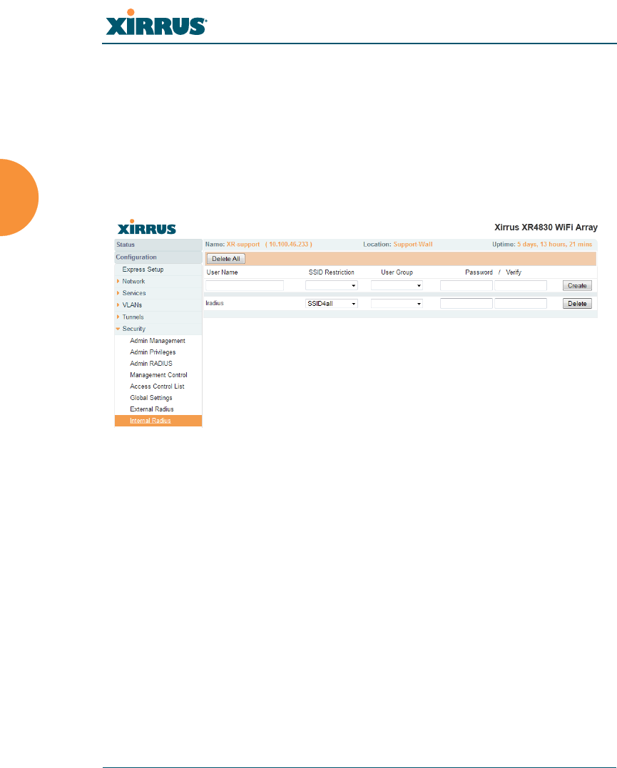
Wireless Array
238 Configuring the Wireless Array
Internal Radius
This window allows you to define the parameters for the Array’s internal
RADIUS server for user authentication. However, the internal RADIUS server
will only authenticate wireless clients that want to associate to the Array. This can
be useful if an external RADIUS server is not available. To set up the internal
RADIUS server, you must choose Internal as the RADIUS server mode in Global
Settings. Refer to “Global Settings” on page 230.
Figure 131. Internal RADIUS Server
Clients using PEAP may have difficulty authenticating to the Array using
the Internal RADIUS server due to invalid security certificate errors. To
prevent this problem, the user may disable the Validate Server Certificate
option on the station. Do this by displaying the station’s wireless devices and
then displaying the properties of the desired wireless interface. In the
security properties, disable Validate server certificate. In some systems,
this may be found by setting the authentication method to PEAP and
changing the associated settings.

Wireless Array
Configuring the Wireless Array 239
Procedure for Creating a New User
1. User Name: Enter the name of the user that you want to authenticate to
the internal RADIUS server.
2. SSID Restriction: (Optional) If you want to restrict this user to
associating to a particular SSID, choose an SSID from the pull-down list.
3. User Group: (Optional) If you want to make this user a member of a
previously defined user group, choose a group from the pull-down list.
This will apply all of the user group’s settings to the user. See
“Understanding Groups” on page 264.
4. Password: (Optional) Enter a password for the user.
5. Verify: (Optional) Retype the user password to verify that you typed it
correctly.
6. Click on the Create button to add the new user to the list.
Procedure for Managing Existing Users
1. SSID Restriction: (Optional) If you want to restrict a user to associating
to a particular SSID, choose an SSID from its pull-down list.
2. User Group: (Optional) If you want to change the user’s group, choose a
group from the pull-down list. This will apply all of the user group’s
settings to the user. See “Understanding Groups” on page 264.
3. Password: (Optional) Enter a new password for the selected user.
4. Verify Password: (Optional) Retype the user password to verify that you
typed it correctly.
5. If you want to delete one or more users, click their Delete buttons.
6. Click Save changes to flash if you wish to make your changes
permanent.
See Also
Admin Management
External Radius
Global Settings (IAP)
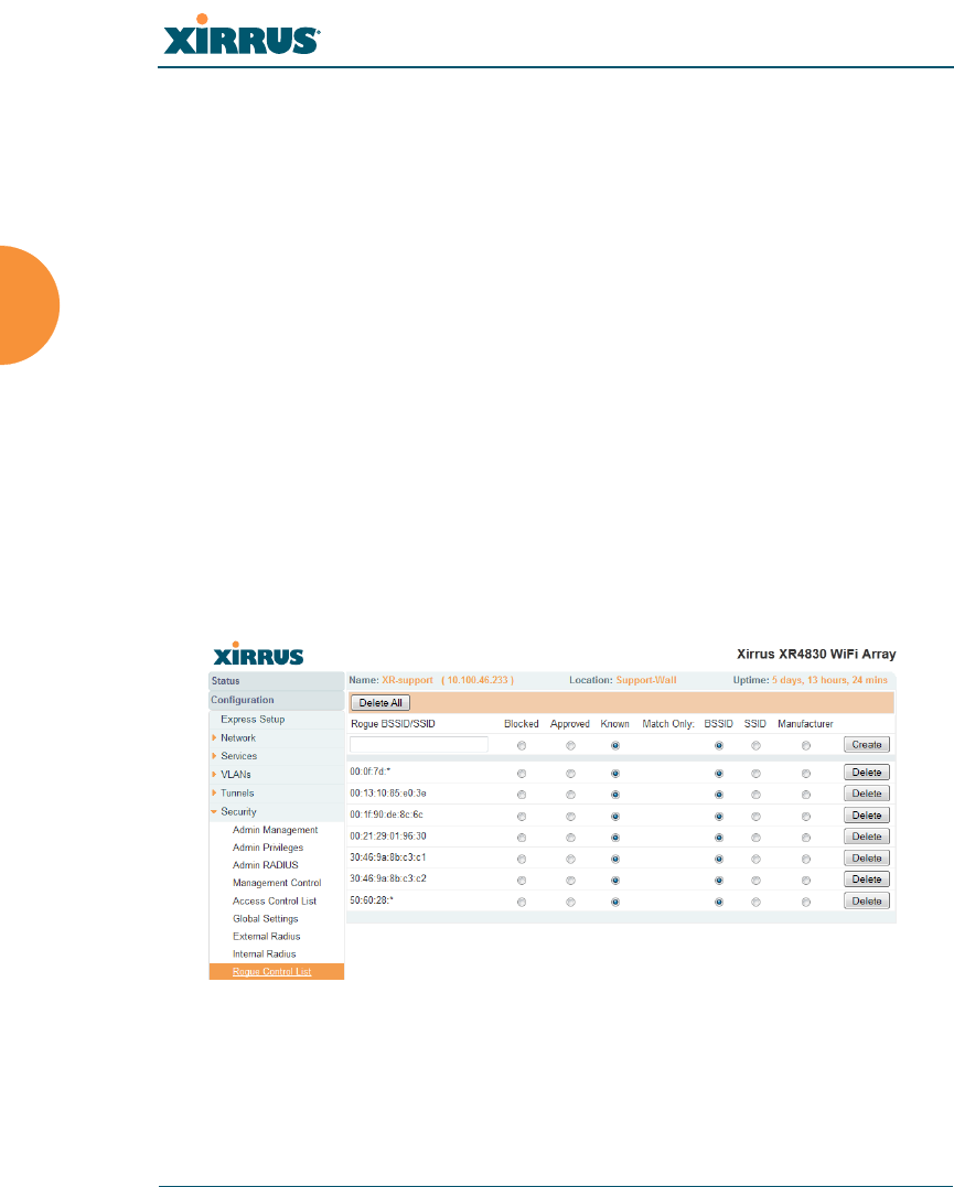
Wireless Array
240 Configuring the Wireless Array
Access Control List
Management Control
Security
Understanding Groups
Rogue Control List
This window allows you to set up a control list for rogue APs, based on a type
that you define. You may classify rogue APs as blocked, so that the Array will
take steps to prevent stations from associating with the blocked AP. See “About
Blocking Rogue APs” on page 331. The Array can keep up to 5000 entries in this
list.
Figure 132. Rogue Control List
The RF Monitor > Intrusion Detection window provides an alternate
method for classifying rogues. You can list all Unknown stations and select
all the rogues that you’d like to set to Known or Approved, rather than
entering the SSID/BSSID as described below. See “Intrusion Detection”
on page 119.

Wireless Array
Configuring the Wireless Array 241
Procedure for Establishing Rogue AP Control
1. Rogue BSSID/SSID: Enter the BSSID, SSID, or manufacturer string to
match for the new rogue control entry. The Match Only radio buttons
specify what to match (e.g., the MAC address, SSID, or manufacturer).
You may use the “*” character as a wildcard to match any string at this
position. For example, 00:0f:7d:* matches any string that starts with
00:0f:7d:. Xirrus Arrays start with 00:0f:7d: or 50:60:28:. By default, the
Rogue Control List contains two entries that match 00:0f:7d:* and
50:60:28:* and apply the classification Known to all Xirrus Arrays.
2. Rogue Control Classification: Enter the classification for the specified
rogue AP(s), either Blocked, Known or Approved.
3. Match Only: Select the match criterion to compare the Rogue BSSID/
SSID string against: BSSID, Manufacturer, or SSID. The BSSID field
contains the MAC address.
4. Click Create to add this rogue AP to the Rogue Control List.
5. Rogue Control List: If you want to edit the control type for a rogue AP,
just click the radio button for the new type for the entry: Blocked, Known
or Approved.
6. To delete rogue APs from the list, click their Delete buttons.
7. Click Save changes to flash if you wish to make your changes
permanent.
See Also
Network Map
Intrusion Detection
SSIDs
SSID Management
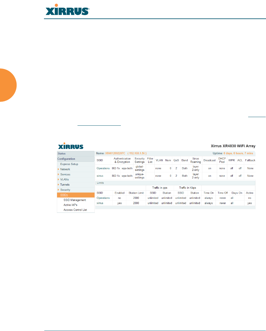
Wireless Array
242 Configuring the Wireless Array
SSIDs
This status-only window allows you to review SSID (Service Set IDentifier)
assignments. It includes the SSID name, whether or not an SSID is visible on the
network, any security and QoS parameters defined for each SSID, associated
VLAN IDs, radio availability, and DHCP pools defined per SSID. Click on an
SSID’s name to jump to the edit page for the SSID. There are no configuration
options available on this page, but if you are experiencing problems or reviewing
SSID management parameters, you may want to print this page for your records.
Figure 133. SSIDs
The read-only Limits section of the SSIDs window allows you to review any
limitations associated with your defined SSIDs. For example, this window shows
the current state of an SSID (enabled or not), how much SSID and station traffic is
allowed, time on and time off, days on and off, and whether each SSID is
currently active or inactive.
For information to help you understand SSIDs and how multiple SSIDs are
managed by the Wireless Array, go to “Understanding SSIDs” on page 243 and
the Multiple SSIDs section of “Frequently Asked Questions” on page 452. For a
description of how QoS operates on the Array, see “Understanding QoS Priority
on the Wireless Array” on page 244.
For a complete discussion of implementing Voice over Wi-Fi on the Array,
see the Xirrus Voice over Wireless Application Note in the Xirrus
Resource Center.

Wireless Array
Configuring the Wireless Array 243
SSIDs are managed with the following windows:
“SSID Management” on page 249
“Active IAPs” on page 261
“Per-SSID Access Control List” on page 262
SSIDs are discussed in the following topics:
“Understanding SSIDs” on page 243
“Understanding QoS Priority on the Wireless Array” on page 244
Understanding SSIDs
The SSID (Service Set Identifier) is a unique identifier that wireless networking
devices use to establish and maintain wireless connectivity. Multiple access points
on a network or sub-network can use the same SSIDs. SSIDs are case-sensitive
and can contain up to 32 alphanumeric characters (do not include spaces when
defining SSIDs).
Multiple SSIDs
A BSSID (Basic SSID) refers to an individual access point radio and its associated
clients. The identifier is the MAC address of the access point radio that forms the
BSS. A group of BSSs can be formed to allow stations in one BSS to communicate
to stations in another BSS via a backbone that interconnects each access point.
The Extended Service Set (ESS) refers to the group of BSSIDs that are grouped
together to form one ESS. The ESSID (often referred to as SSID or “wireless
network name”) identifies the Extended Service Set. Clients must associate to a
single ESS at any given time. Clients ignore traffic from other Extended Service
Sets that do not have the same SSID.
Legacy access points typically support one SSID per access point. Wireless Arrays
support the ability to define and use multiple SSIDs simultaneously.
Using SSIDs
The creation of different wireless network names allows system administrators to
separate types of users with different requirements. The following policies can be
tied to an SSID:
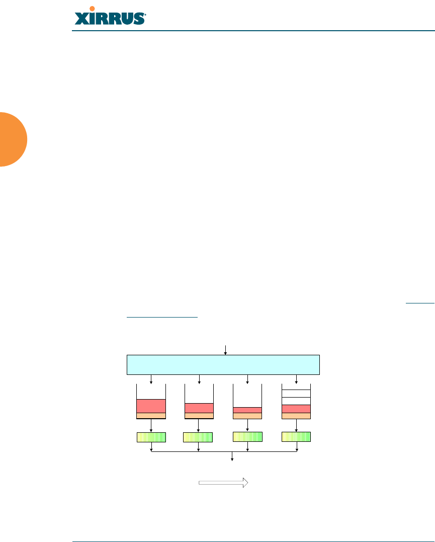
Wireless Array
244 Configuring the Wireless Array
The wireless security mode needed to join this SSID.
The wireless Quality of Service (QoS) desired for this SSID.
The wired VLAN associated with this SSID.
As an example, one SSID named accounting might require the highest level of
security, while another named guests might have low security requirements.
Another example may define an SSID named voice that supports voice over
Wireless LAN phones with the highest Quality of Service (QoS) definition. This
SSID might also forward traffic to specific VLANs on the wired network.
See Also
SSID Management
SSIDs
Understanding SSIDs
Understanding QoS Priority on the Wireless Array
Figure 134. Four Traffic Classes
For a complete discussion of implementing Voice over Wi-Fi on the Array,
see the Xirrus Voice over Wireless Application Note in the Xirrus
Resource Center.
Mapping to
Traffic Class
Four Transmit
Queues
Per queue
channel access
Application Data
Voice
Data Video
Data Background
Data Best Effort
Data
IAP (Transmit)
Highest
Priority Lowest
Priority
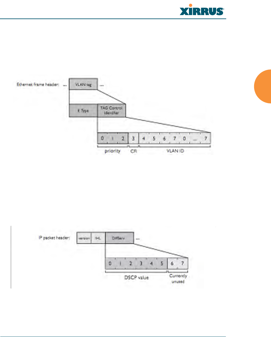
Wireless Array
Configuring the Wireless Array 245
The Wireless Array’s Quality of Service Priority feature (QoS) allows traffic to be
prioritized according to your requirements. For example, you typically assign the
highest priority to voice traffic, since this type of traffic requires delay to be under
10 ms. The Array has four separate queues for handling wireless traffic at
different priorities, and thus it supports four traffic classes (QoS levels).
Figure 135. Priority Level—IEEE 802.1p (Layer 2)
IEEE802.1p uses three bits in an Ethernet frame header to define eight priority
levels at the MAC level (Layer 2) for wired networks. Each data packet may be
tagged with a priority level, i.e., a user priority tag. Since there are eight possible
user priority levels and the Array implements four wireless QoS levels, user
priorities are mapped to QoS as described below.
Figure 136. Priority Level—DSCP (DiffServ - Layer 3)
DSCP (Differentiated Services Code Point or DiffServ) uses 6 bits in the IPv4 or
IPv6 packet header, defined in RFC2474 and RFC2475. The DSCP value classifies

Wireless Array
246 Configuring the Wireless Array
a Layer 3 packet to determine the Quality of Service (QoS) required. DSCP
replaces the outdated Type of Service (TOS) field.
The description below describes how both of these priority levels are mapped to
the Array’s four traffic classes.
End-to-End QoS Handling
Wired QoS - Ethernet Port:
Ingress: Incoming wired packets are assigned QoS priority based on their
SSID and 802.1p tag (if any), as shown in the table below. This table
follows the mapping recommended by IEEE802.11e.
FROM
Priority Tag
802.1p (Wired)
TO
Array QoS
(Wireless) Typical Use
0 0 (Lowest
priority) Best Effort
1 1 Background — explicitly designated as
low-priority and non-delay sensitive
21Spare
3 0 Excellent Effort
42Controlled Load
52Video
6 3 Voice - requires delay <10ms
7 (Highest
priority) 3 (Highest
priority) Network control
Wireless Array
Configuring the Wireless Array 247
Egress: Outgoing wired packets are IEEE 802.1p tagged at the Ethernet
port for upstream traffic, thus enabling QoS at the edge of the network.
Wireless QoS - Radios:
Each SSID can be assigned a separate QoS priority (i.e., traffic class) from
0 to 3, where 3 is highest priority and 2 is the default. See “SSID
Management” on page 249. If multiple SSIDs are used, packets from the
SSID with higher priority are transmitted first.
The Array supports IEEE802.11e Wireless QoS for downstream traffic.
Higher priority packets wait a shorter time before gaining access to the
air and contend less with all other 802.11 devices on a channel.
How QoS is set for a packet in case of conflicting values:
a. If an SSID has a QoS setting, and an incoming wired packet’s user
priority tag is mapped to a higher QoS value, then the higher QoS
value is used.
b. If a group or filter has a QoS setting, this overrides the QoS value
above. See “Groups” on page 264, and “Filters” on page 344.
c. Voice packets have the highest priority (see Voice Support, below).
d. If DSCP to QoS Mapping Mode is enabled, the IP packet is mapped
to QoS level 0 to 3 as specified in the DSCP Mappings table. This
value overrides any of the settings in cases a to c above.
In particular, by default:
•DSCP 8 is set to QoS level 1.
FROM
Array QoS (Wireless) TO
Priority Tag 802.1p (Wired)
1 (Lowest priority) 1
00
2 (Default) 5
3 (Highest priority) 6

Wireless Array
248 Configuring the Wireless Array
•DSCP 40 is typically used for video traffic and is set to QoS
level 2.
•DSCP 48 is typically used for voice traffic and is set to QoS
level 3—the highest level
•All other DSCP values are set to QoS level 0 (the lowest level—
Best Effort).
Packet Filtering QoS classification
Filter rules can be used to redefine the QoS priority level to override
defaults. See “Filter Management” on page 347. This allows the QoS
priority level to be assigned based on protocol, source, or destination.
Voice Support
The QoS priority implementation on the Array give voice packets the
highest priority to support voice applications.
High Density 2.4G Enhancement—Honeypot SSID
Some situations pose problems for all wireless APs. For example, iPhones will
remember every SSID and flood the airwaves with probes, even when the user
doesn’t request or desire this behavior. In very high density deployments, these
probes can consume a significant amount of the available wireless bandwidth.
The Array offers a feature targeting this problem—a “honeypot” SSID. Simply
create an SSID named honeypot on the Array. Once this SSID is created and
enabled, it will respond to any station probe looking for an open (unencrypted)
SSID that is not configured on the Array.
Traffic for a station connected to the honeypot SSID may be handled in a various
ways:
it may be directed to WPR to display a splash page or offer the user the
opportunity to sign in to your service (see “Web Page Redirect
Configuration Settings” on page 255);
it may be filtered;
or it may be dead-ended by defining a specific dead-end VLAN on the
honeypot SSID to “trap” stations.
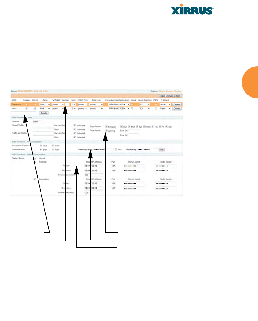
Wireless Array
Configuring the Wireless Array 249
Use the honeypot feature carefully as it could interfere with legitimate SSIDs and
prevent clients from associating to another available network.
SSID Management
This window allows you to manage SSIDs (create, edit and delete), assign security
parameters and VLANs on a per SSID basis, and configure the Web Page Redirect
functionality.
Figure 137. SSID Management
Create new SSID
Configure parameters Set traffic limits / usage schedule
Configure encryption/authentication
Configure RADIUS server

Wireless Array
250 Configuring the Wireless Array
Procedure for Managing SSIDs
1. New SSID Name: To create a new SSID, enter a new SSID name to the left
of the Create button (Figure 137), then click Create. The SSID name may
only consist of the characters A-Z, a-z, 0-9, dash, and underscore. You
may create up to 16 SSIDs.
SSID List (top of page)
2. SSID: Shows all currently assigned SSIDs. When you create a new SSID,
the SSID name appears in this table. Click any SSID in this list to select it.
3. On: Check this box to activate this SSID or clear it to deactivate it.
4. Brdcast: Check this box to make the selected SSID visible to all clients on
the network. Although the Wireless Array will not broadcast SSIDs that
are hidden, clients can still associate to a hidden SSID if they know the
SSID name to connect to it. Clear this box if you do not want this SSID to
be visible on the network.
5. Band: Choose which wireless band the SSID will be beaconed on. Select
either 5 GHz — 802.11an, 2.4 GHz — 802.11bgn or Both.
6. VLAN ID / Number: From the pull-down list, select a VLAN that you
want this traffic to be forwarded to on the wired network. Select numeric
to enter the number of a previously defined VLAN in the Number field
(see “VLANs” on page 199). This step is optional.
7. QoS: (Optional) Select a value in this field for QoS (Quality of Service)
priority filtering. The QoS value must be one of the following:
•0 — The lowest QoS priority setting, where QoS makes its best effort
at filtering and prioritizing data, video and voice traffic without
compromising the performance of the network. Use this setting in
environments where traffic prioritization is not a concern.
•1 — Medium, with QoS prioritization aggregated across all traffic
types.
•2 — High, normally used to give priority to video traffic.

Wireless Array
Configuring the Wireless Array 251
•3 — The highest QoS priority setting, normally used to give priority to
voice traffic.
The QoS setting you define here will prioritize wireless traffic for this
SSID over other SSID traffic, as described in “Understanding QoS Priority
on the Wireless Array” on page 244. The default value for this field is 2.
8. DHCP Pool: If you want to associate an internal DHCP pool to this SSID,
choose the pool from the pull--down list. An internal DHCP pool must be
created before it can be assigned. To create an internal DHCP pool, go to
“DHCP Server” on page 197.
9. Filter List: If you wish to apply a set a filters to this SSID’s traffic, select
the desired Filter List. See “Filters” on page 344.
10. Authentication: The following authentication options are available:
•Open: This option provides no authentication and is not
recommended.
•RADIUS MAC: Uses an external RADIUS server to authenticate
stations onto the wireless network, based on the user’s MAC address.
Accounting for these stations is performed according to the
accounting options that you have configured specifically for this SSID
or globally (see Step 12 below).
•802.1x: Authenticates stations onto the wireless network via a
RADIUS server using 802.1x with EAP. The RADIUS server can be
internal (provided by the Wireless Array) or external.
11. Encryption: From the pull-down list, choose the encryption that will be
required — specific to this SSID — either None, WEP, WPA, WPA2 or
WPA-Both. The None option provides no security and is not
recommended; WPA2 provides the best practice Wi-Fi security.
If this SSID is on a VLAN, the VLAN must have management turned on in
order to pass CHAP authentication challenges from the client station to the
RADIUS server.

Wireless Array
252 Configuring the Wireless Array
Each SSID supports only one encryption type at a time (except that WPA
and WPA2 are both supported on an SSID if you select WPA-Both). If you
need to support other encryption types, you must define additional
SSIDs. The encryption standard used with WPA or WPA2 is selected in
the Security>Global Settings window (page 230). For an overview of the
security options, see “Security Planning” on page 46 and “Understanding
Security” on page 209.
12. Global: Check the checkbox if you want this SSID to use the security
settings established at the global level (refer to “Global Settings” on
page 230). Clear the checkbox if you want the settings established here to
take precedence. Additional sections will be displayed to allow you to
configure encryption, RADIUS, and RADIUS accounting settings. The
WPA Configuration encryption settings have the same parameters as
those described in “Procedure for Configuring Network Security” on
page 231. The external RADIUS and accounting settings are configured in
the same way as for an external RADIUS server (see “Procedure for
Configuring an External RADIUS Server” on page 235). Note that
external RADIUS servers may be specified using IP addresses or domain
names.
XN model Arrays cannot use the SSID-specific WEP keys specified in this
step. They can only use the global WEP keys specified in the Global
Settings window.
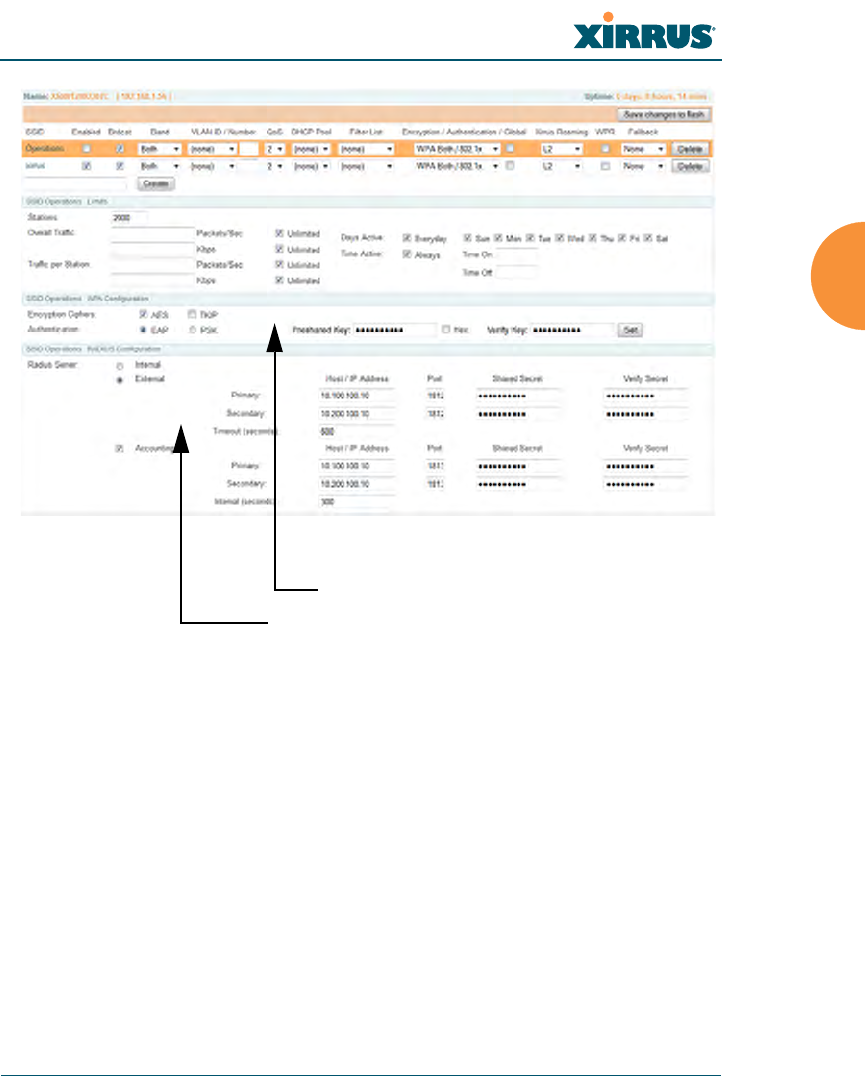
Wireless Array
Configuring the Wireless Array 253
.
Figure 138. SSID Management
13. Roaming: For this SSID, select whether to enable fast roaming between
IAPs or Arrays at L2&L3 (Layer 2 and Layer 3), at L2 (Layer 2 only), or
disable roaming (Off). You may only select fast roaming at Layers 2 and 3
if this has been selected in Global Settings (IAP). See “Understanding Fast
Roaming” on page 273.
14. WPR (Web Page Redirect): Check the checkbox to enable the Web Page
Redirect functionality, or clear it to disable this option. If enabled, WPR
configuration fields will be displayed under the SSID Limits section. This
feature may be used to provide an alternate mode of authentication, or to
simply display a splash screen when a user first associates to the wireless
network. After that, it can (optionally) redirect the user to an alternate
Set Encryption
Configure Radius, Accounting

Wireless Array
254 Configuring the Wireless Array
URL. For example, some wireless devices and users may not have a
correctly configured 802.1x (RADIUS) supplicant. Utilizing WPR’s Web-
based login, users may be authenticated without using an 802.1x
supplicant. See “Web Page Redirect Configuration Settings” on page 255
for details of WPR usage and configuration.
15. Fallback: Network Assurance checks network connectivity for the Array.
When Network Assurance detects a failure, perhaps due to a bad link or
WDS failure, if Fallback is set to Disable the Array will automatically
disable this SSID. This will disassociate current clients, and prevent new
clients from associating. Since the Array’s network connectivity has
failed, this gives clients a chance to connect to other, operational parts of
the wireless network. No changes are made to WDS configuration. See
Step a on page 225 for more information on Network Assurance.
The lower part of the window contains a few sections of additional settings to
configure for the currently selected SSID, depending on the values chosen for the
settings described above.
“SSID Limits” on page 254
“Web Page Redirect Configuration Settings” on page 255
“WPA Configuration Settings” on page 259
“RADIUS Configuration Settings” on page 260
SSID Limits
See “Group Limits” on page 268 for a discussion of the interaction of SSID limits
and group limits. To eliminate confusion, we recommend that you configure one
set of limits or the other, but not both.
16. Stations: Enter the maximum number of stations allowed on this SSID.
This step is optional. Note that the IAPs - Global Settings window also
has a station limit option — Max Station Association per IAP. If both
When using WPR, it is particularly important to adhere to the SSID
naming restrictions detailed in Step 1.

Wireless Array
Configuring the Wireless Array 255
station limits are set, both will be enforced. As soon as either limit is
reached, no new stations can associate until some other station has
terminated its association.
17. Overall Traffic: Choose Unlimited if you do not want to place a
restriction on the traffic for this SSID, or enter a value in the Packets/Sec
field to force a traffic restriction.
18. Traffic per Station: Choose Unlimited if you do not want to place a
restriction on the traffic per station for this SSID, or enter a value in the
Packets/Sec field or the Kbps field to force a traffic restriction. If you set
both values, the Array will enforce the limit it reaches first.
19. Days Active: Choose Everyday if you want this SSID to be active every
day of the week, or select only the specific days that you want this SSID to
be active. Days that are not checked are considered to be the inactive
days.
20. Time Active: Choose Always if you want this SSID active without
interruption, or enter values in the Time On and Time Off fields to limit
the time that this SSID is active.
21. To delete SSIDs, click their Delete buttons.
22. Click Save changes to flash if you wish to make your changes
permanent.
Web Page Redirect Configuration Settings
If you enable WPR, the SSID Management window displays additional fields that
must be configured. For example configurations and complete examples, please
see the Xirrus Web Page Redirect Application Note in the Xirrus Resource Center.
If enabled, WPR displays a splash or login page when a user associates to the
wireless network and opens a browser to any URL (provided the URL does not
point to a resource directly on the user’s machine). The user-requested URL is
captured, the user’s browser is redirected to the splash or login page, and then the
browser is redirected either to your specified landing page, if any, or else back to
the captured URL. The landing page may be specified for a user group as well.
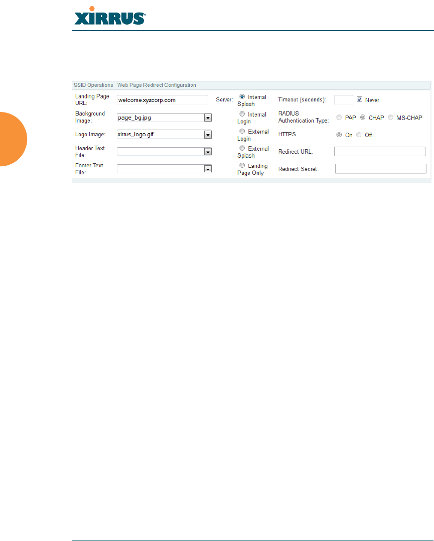
Wireless Array
256 Configuring the Wireless Array
See “Group Management” on page 266. Note that if you change the management
HTTPS port, WPR uses that port, too. See “HTTPS” on page 224.
Figure 139. WPR Internal Splash Page Fields (SSID Management)
Note that when users roam between Arrays, their WPR Authentication will
follow them so that re-authentication is not required.
You may select among five different modes for use of the Web Page Redirect
feature, each displaying a different set of parameters that must be entered:
Internal Login page
This option displays a login page (residing on the Array) instead of the
first user-requested URL. There is an upload function that allows you to
replace the default login page, if you wish. Please see “Web Page
Redirect” on page 368 for more information.
To set up internal login, set Server to Internal Login. Set HTTPS to On
for a secure login, or select Off to use HTTP. You may also customize the
login page with logo and background images and header and footer text.
See “Customizing an Internal Login or Splash page” on page 258.
The user name and password are obtained by the login page, and
authentication occurs according to your configured authentication
information (starting with Step 10 on page 251 above). These
authentication parameters are configured as described in “Procedure for
Configuring Network Security” on page 231.

Wireless Array
Configuring the Wireless Array 257
After authentication, the browser is redirected back to the captured URL.
If you want the user redirected to a specific landing page instead, enter its
address in Landing Page URL.
Internal Splash page
This option displays a splash page instead of the first user-requested
URL. The splash page files reside on the Array. Note that there is an
upload function that allows you to replace the default splash page, if you
wish. Please see “Web Page Redirect” on page 368 for more information.
You may also customize the splash page with logo and background
images and header and footer text. See “Customizing an Internal Login or
Splash page” on page 258.
To use an internal splash page, set Server to Internal Splash. Enter a
value in the Timeout field to define how many seconds the splash screen
is displayed before timing out, or select Never to prevent the page from
timing out automatically. After the splash page, the user is redirected to
the captured URL. If you want the user redirected to a specific landing
page instead, enter its address in Landing Page URL.
External Login page
This option redirects the user to a login page on an external web server
for authentication, instead of the first user-requested URL. Login
information (user name and password) must be obtained by that page,
and returned to the Array for authentication.
Authentication occurs according to your configured RADIUS
information. These parameters are configured as described in “Procedure
for Configuring Network Security” on page 231, except that the RADIUS
Authentication Type is selected here, as described below. After
authentication, the browser is redirected back to the captured URL. If you
want the user redirected to a specific landing page instead, enter its
address in Landing Page URL.
Both the Internal Login and External Login options of WPR perform
authentication using your configured RADIUS servers.

Wireless Array
258 Configuring the Wireless Array
To set up external login page usage, set Server to External Login. Enter
the URL of the external web server in Redirect URL, and enter that
server’s shared secret in Redirect Secret.
Select the RADIUS Authentication Type. This is the protocol used for
authentication of users, CHAP or PAP (the default).
•PAP (Password Authentication Protocol), is a simple protocol. PAP
transmits ASCII passwords over the network “in the clear”
(unencrypted) and is therefore considered insecure.
•CHAP (Challenge-Handshake Authentication Protocol) is a more
secure Protocol. The login request is sent using a one-way hash
function.
External Splash page
This option displays a splash page instead of the first user-requested
URL. The splash page files reside on an external web server.
To set up external splash page usage, set Server to External Splash. Enter
the URL of the external web server in Redirect URL, and enter that
server’s shared secret in Redirect Secret.
After the splash page, the user is redirected to the captured URL. If you
want the user redirected to a specific landing page instead, enter its
address in Landing Page URL.
Landing Page Only
This option redirects the user to a specific landing page. If you select this
option, enter the desired address in Landing Page URL.
Customizing an Internal Login or Splash page
You may customize these pages with a logo and/or background image, and
header and/or footer text, as shown below in Figure 140.
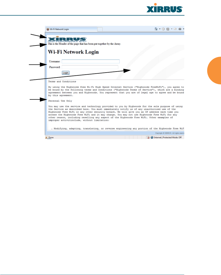
Wireless Array
Configuring the Wireless Array 259
Figure 140. Customizing an Internal Login or Splash Page
Background Image — specify an optional jpg, gif, or png file to display in
the background of the page. Other customizations (logo, header, footer)
will overlay the background, so that it will not be visible in those areas.
Logo Image — specify an optional jpg, gif, or png file to display at the top
of the page.
Header Text File — specify an optional .txt file to display at the top of the
page (beneath the logo, if any).
Footer Text File — specify an optional .txt file to display at the bottom of
the page.
WPA Configuration Settings
If you set Encryption for this SSID to one of the WPA selections (Step 11 on
page 251) and you did not check the Global checkbox (Step 12), this section will
be displayed. The WPA Configuration encryption settings have the same
Logo
Internal
Login Page
Background
Footer
Header

Wireless Array
260 Configuring the Wireless Array
parameters as those described in “Procedure for Configuring Network Security”
on page 231
RADIUS Configuration Settings
The RADIUS settings section will be displayed if you set Authentication (Step 10
on page 251) to RADIUS MAC and you did not check the Global checkbox (Step
12). This means that you wish to set up a RADIUS server to be used for this
particular SSID. If Global is checked, then the security settings (including the
RADIUS server, if any) established at the global level are used instead (see
“Global Settings” on page 230).
The RADIUS and accounting settings are configured in the same way as for an
external RADIUS server (see “Procedure for Configuring an External RADIUS
Server” on page 235).
See Also
DHCP Server
External Radius
Global Settings (IAP)
Internal Radius
Security Planning
SSIDs
Understanding QoS Priority on the Wireless Array
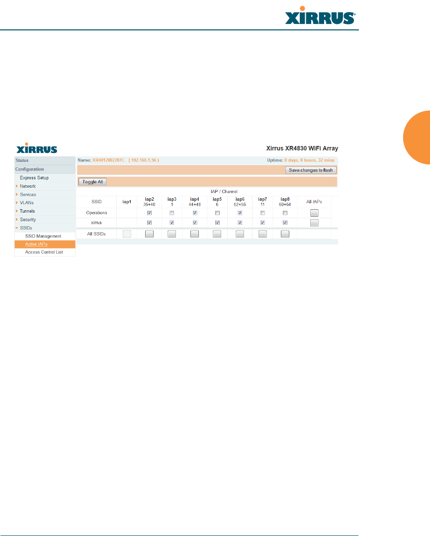
Wireless Array
Configuring the Wireless Array 261
Active IAPs
By default, when a new SSID is created, that SSID is active on all IAPs. This
window allows you to specify which IAPs will offer that SSID. Put differently,
you can specify which SSIDs are active on each IAP.
This feature is useful in conjunction with WDS. You may use this window to
configure the WDS link IAPs so that only the WDS link SSIDs are active on them.
Figure 141. Setting Active IAPs per SSID
Procedure for Specifying Active IAPs
1. SSID: For a given SSID row, check off the IAPs on which that SSID is to
be active. Uncheck any IAPs which should not offer that SSID.
2. All IAPs: This button, in the last column, may be used to deny this SSID
on all IAPs. Click again to activate the SSID on all IAPs.
3. All SSIDs: This button, in the bottom row, may be used to activate all
SSIDs on this IAP. Click again to deny all SSIDs on this IAP.
4. Toggle All: This button, on the lower left, may be used to deny all SSIDs
on all IAPs. Click again to activate all SSIDs on all IAPs.
5. Click Save changes to flash if you wish to make your changes
permanent.
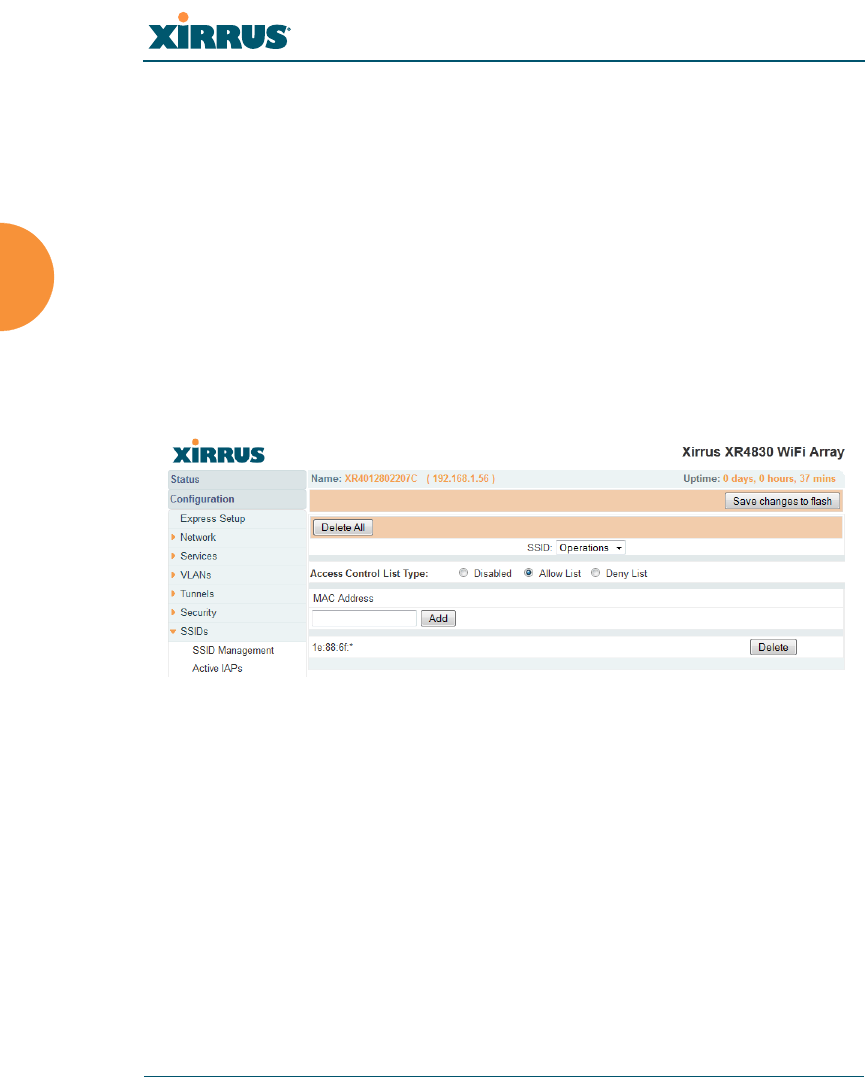
Wireless Array
262 Configuring the Wireless Array
Per-SSID Access Control List
This window allows you to enable or disable the use of the per-SSID Access
Control List (ACL), which controls whether a station with a particular MAC
address may associate to this SSID. You may create access control list entries and
delete existing entries, and control the type of list.
There is one ACL per SSID, and you may select whether its type is an Allow List
or a Deny List, or whether use of this list is disabled. You may create up to 1000
entries per SSID.
There is also a global ACL (see “Access Control List” on page 227). If the same
MAC address is listed in both the global ACL and in an SSID’s ACL, and if either
ACL would deny that station access to that SSID, then access will be denied.
Figure 142. Per-SSID Access Control List
Procedure for Configuring Access Control Lists
1. SSID: Select the SSID whose ACL you wish to manage.
2. Access Control List Type: Select Disabled to disable use of the Access
Control List for this SSID, or select the ACL type — either Allow List or
Deny List.
•Allow List: Only allows the listed MAC addresses to associate to
the Array. All others are denied.

Wireless Array
Configuring the Wireless Array 263
•Deny List: Denies the listed MAC addresses permission to
associate to the Array. All others are allowed.
3. MAC Address: If you want to add a MAC address to the ACL, enter the
new MAC address here, then click the Add button. The MAC address is
added to the ACL. You may use a wildcard (*) for one or more digits to
match a range of addresses. Delete: You may delete selected MAC
addresses from this list by clicking their Delete buttons.
4. Delete All: This button, on the upper left, may be used to delete all the
MAC entries in an ACL.
5. Click Save changes to flash if you wish to make your changes
permanent.
In addition to these lists, other authentication methods (for
example, RADIUS) are still enforced for users.
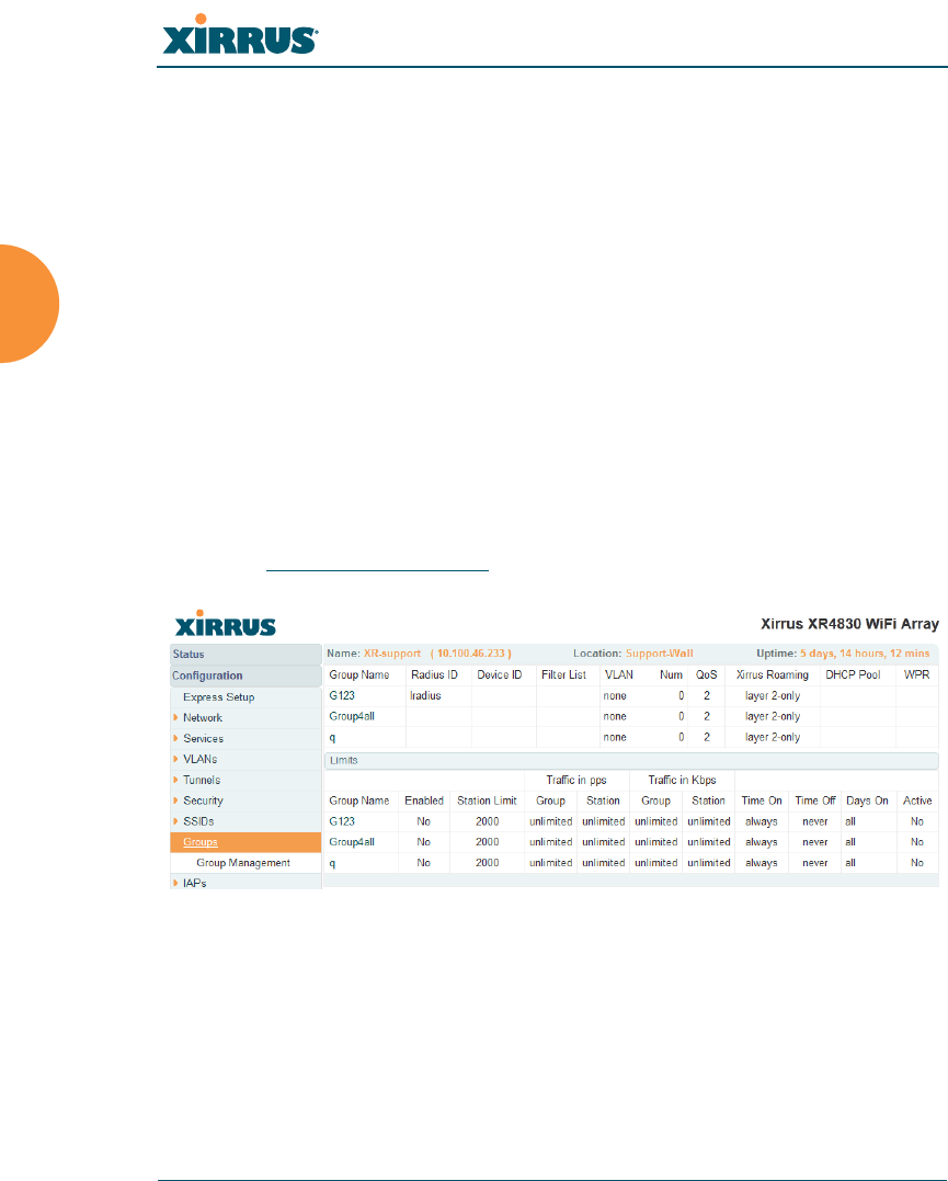
Wireless Array
264 Configuring the Wireless Array
Groups
This is a status-only window that allows you to review user (i.e., wireless client)
Group assignments. It includes the group name, Radius ID, Device ID, VLAN IDs
and QoS parameters and roaming layer defined for each group, and DHCP pools
and web page redirect information defined for the group. You may click on a
group’s name to jump to the edit page for the group. There are no configuration
options available on this page, but if you are experiencing problems or reviewing
group management parameters, you may want to print this page for your records.
The Limits section of this window shows any limitations configured for your
defined groups. For example, this window shows the current state of a group
(enabled or disabled), how much group and per-station traffic is allowed, time on
and time off, and days on and off.
For information to help you understand groups, see Understanding Groups
below. For an in-depth discussion, please see the Xirrus User Groups Application
Note in the Xirrus Resource Center.
Figure 143. Groups
Understanding Groups
User groups allow administrators to assign specific network parameters to users
(wireless clients) through RADIUS privileges rather than having to map users to
an SSID tailored for that set of privileges. Groups provide flexible control over
user privileges without the need to create large numbers of SSIDs.

Wireless Array
Configuring the Wireless Array 265
A group allows you to define a set of parameter values to be applied to selected
users. For example, you might define the user group Students, and set its VLAN,
security parameters, web page redirect (WPR), and traffic limits. When a new user
is created, you can apply all of these settings just by making the user a member of
the group. The group allows you to apply a uniform configuration to a set of users
in one step.
In addition, you can restrict the group so that it only applies its settings to group
members who are connecting using a specific device type, such as iPad or phone.
Thus, you could define a group named Student-Phone with Device ID set to
Phone, and set the group’s VLAN Number to 100. This group’s settings will only
be applied to group members who connect using a phone, and they will all use
VLAN 100. Note that settings for the group in the RADIUS server will override
any settings on this WMI page.
Almost all of the parameters that can be set for a group are the same as SSID
parameters. This allows you to configure features at the user group level, rather
than for an entire SSID. If you set parameter values for an SSID, and then enter
different values for the same parameters for a user group, the user group values
have priority (i.e., group settings will override SSID settings).
Group names are case-sensitive and can contain up to 32 alphanumeric characters
(do not include spaces when defining Groups).
Using Groups
User accounts are used to authenticate wireless clients that want to associate to
the Array. These accounts are established in one of two ways, using the Security>
Internal Radius window or the Security> External Radius window. In either
case, you may select a user group for the user, and that user group’s settings will
apply to the user:
Internal Radius — when you add or modify a user entry, select a user
group to which the user will belong.
External Radius — when you add or modify a user account, specify the
Radius ID for the user group to which the user will belong. This must be
the same Radius ID that was entered in the Group Management window.
When the user is authenticated, the external Radius server will send the
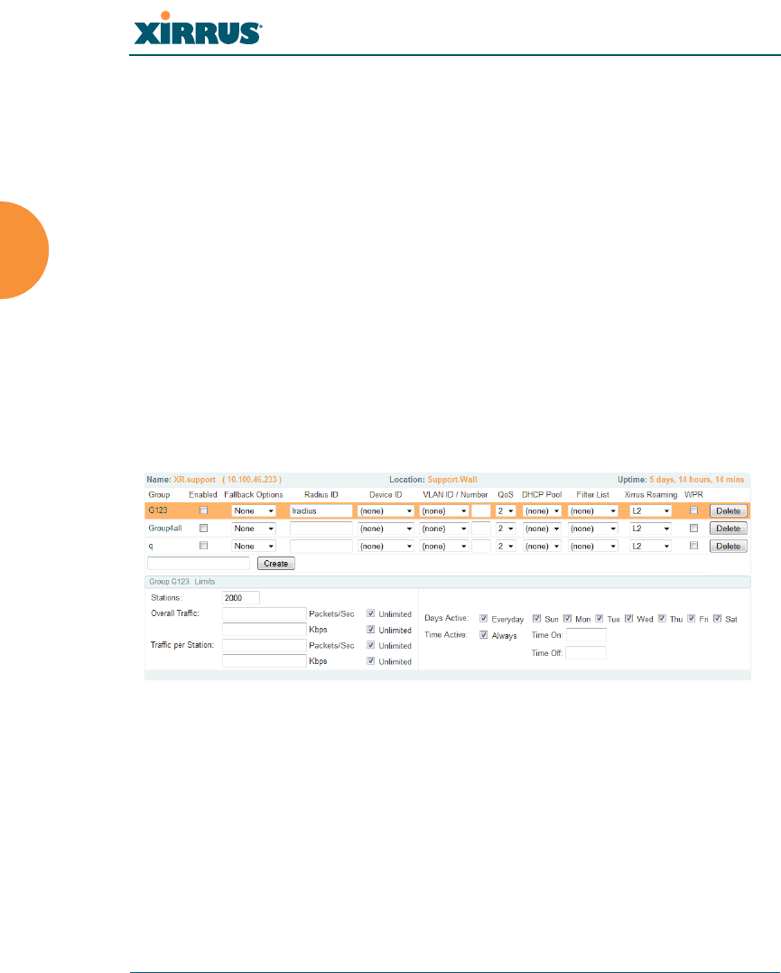
Wireless Array
266 Configuring the Wireless Array
Radius ID to the Array. This will allow the Array to identify the group to
which the user belongs.
See Also
External Radius
Internal Radius
SSIDs
Understanding QoS Priority on the Wireless Array
Web Page Redirect Configuration Settings
Understanding Fast Roaming
Group Management
This window allows you to manage groups (create, edit and delete), assign usage
limits and other parameters on a per group basis, and configure the Web Page
Redirect functionality.
Figure 144. Group Management
Procedure for Managing Groups
1. New Group Name: To create a new group, enter a new group name next
to the Create button, then click Create. You may create up to 16 groups.
To configure and enable this group, proceed with the following steps.
2. Group: This column lists currently defined groups. When you create a
new group, the group name appears in this list. Click on any group to
select it, and then proceed to modify it as desired.

Wireless Array
Configuring the Wireless Array 267
3. Enabled: Check this box to enable this group or leave it blank to disable
it. When a group is disabled, users that are members of the group will
behave as if the group did not exist. In other words, the options
configured for the SSID will apply to the users, rather than the options
configured for the group.
4. Radius ID: Enter a unique Radius ID for the group, to be used on an
external Radius server. When adding a user account to the external
server, this Radius ID value should be entered for the user. When the user
is authenticated, Radius sends this value to the Array. This tells the Array
that the user is a member of the group having this Radius ID.
5. Device ID: You may select a device type from this drop-down list, for
example, Notebook, phone, iPhone, or Android. This allows you to
apply the group settings only if a station authenticates as a user that is a
member of the group and the station’s device type matches Device ID.
Select none if you do not want to consider the device type. If you have a
Radius ID you should not enter a Device ID.
6. VLAN ID: (Optional) From the pull-down list, select a VLAN for this
user’s traffic to use. Select numeric and enter the number of a previously
defined VLAN (see “VLANs” on page 199). This user group’s VLAN
settings supersede Dynamic VLAN settings (which are passed to the
Array by the Radius server). To avoid confusion, we recommend that you
avoid specifying the VLAN for a user in two places.
7. QoS Priority: (Optional) Select a value in this field for QoS (Quality of
Service) priority filtering. The QoS value must be one of the following:
•0 — The lowest QoS priority setting, where QoS makes its best effort
at filtering and prioritizing data, video and voice traffic without
compromising the performance of the network. Use this setting in
environments where traffic prioritization is not a concern.
•1 — Medium; QoS prioritization is aggregated across all traffic types.
•2 — High, normally used to give priority to video traffic.
•3 — The highest QoS priority setting, normally used to give priority to
voice traffic.

Wireless Array
268 Configuring the Wireless Array
The QoS setting you define here will prioritize wireless traffic for this
group versus other traffic, as described in “Understanding QoS Priority
on the Wireless Array” on page 244. The default value for this field is 2.
8. DHCP Pool: (Optional) To associate an internal DHCP pool to this group,
select it from the pull--down list. Only one pool may be assigned. An
internal DHCP pool must be created before it can be assigned. To create a
DHCP pool, go to “DHCP Server” on page 197.
9. Filter List: (Optional) If you wish to apply a set of filters to this user
group’s traffic, select the desired Filter List. See “Filters” on page 344.
10. Xirrus Roaming: (Optional) For this group, select roaming behavior.
Select L2&L3 to enable fast roaming between IAPs or Arrays at Layer 2
and Layer 3. If you select L2, then roaming uses Layer 2 only. You may
only select fast roaming at Layers 2 and 3 if this has been selected in
Global Settings (IAP). You may select Off to disable fast roaming. See
“Understanding Fast Roaming” on page 273.
11. WPR (Web Page Redirect): (Optional) Check this box if you wish to
enable the Web Page Redirect functionality. This will open a Web Page
Redirect details section in the window, where your WPR parameters may
be entered. This feature may be used to display a splash screen when a
user first associates to the wireless network. After that, it can (optionally)
redirect the user to an alternate URL. See “Web Page Redirect
Configuration Settings” on page 255 for details of WPR usage and
configuration. Note that the Group Management window only allows
you to set up an Internal Splash page and a Landing Page URL. The
authentication options that are offered on the SSID Management page are
not offered here. Since the group membership of a user is provided to the
Array by a Radius server, this means the user has already been
authenticated.
Group Limits
The Limits section allows you to limit the traffic or connection times allowed for
this user group. Note that the IAPs — Global Settings window and the SSID
management windows also have options to limit the number of stations, limit

Wireless Array
Configuring the Wireless Array 269
traffic, and/or limit connection times. If limits are set in more than one place, all
limits will be enforced:
As soon as any station limit is reached, no new stations can associate until
some other station has terminated its association.
As soon as any traffic limit is reached, it is enforced.
If any connection date/time restriction applies, it is enforced.
You can picture this as a logical AND of all restrictions. For example, suppose that
a station’s SSID is available MTWTF between 8:00am and 5:00pm, and the User
Group is available MWF between 6:00am and 8:00pm, then the station will be
allowed on MWF between 8:00am and 5:00pm.
To eliminate confusion, we recommend that you configure one set of limits or the
other, but not both.
12. Stations: Enter the maximum number of stations allowed on this group.
The default is 1536.
13. Overall Traffic: Check the Unlimited checkbox if you do not want to
place a restriction on the traffic for this group, or enter a value in the
Packets/Sec field and make sure that the Unlimited box is unchecked to
force a traffic restriction.
14. Traffic per Station: Check the Unlimited checkbox if you do not want to
place a restriction on the traffic per station for this group, or enter a value
in the Packets/Sec or Kbps field and make sure that the Unlimited box is
unchecked to force a traffic restriction.
15. Days Active: Choose Everyday if you want this group to be active every
day of the week, or select only the specific days that you want this group
to be active. Days that are not checked are considered to be the inactive
days.
16. Time Active: Choose Always if you want this group active without
interruption, or enter values in the Time On and Time Off fields to limit
the time that group members may associate.
17. To delete an entry, click its Delete button.

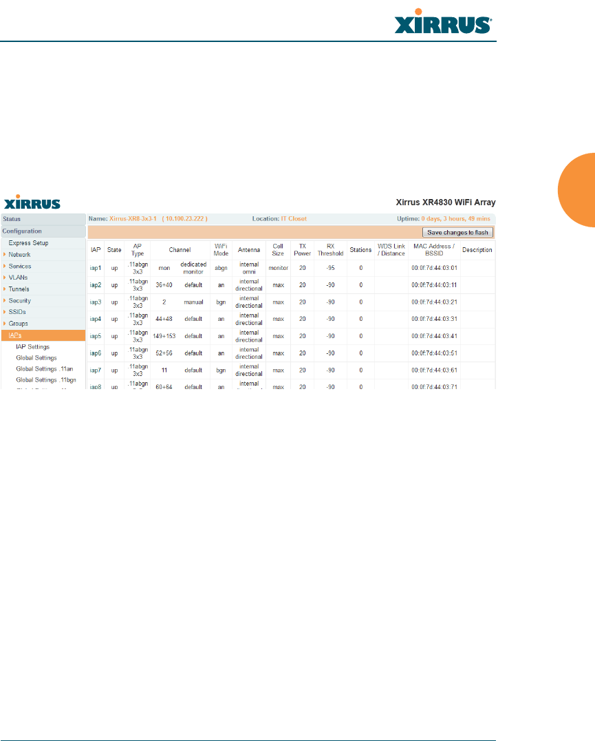
Wireless Array
Configuring the Wireless Array 271
IAPs
This status-only window summarizes the status of the Integrated Access Points
(radios). For each IAP, it shows whether it is up or down, the channel and wireless
mode, the antenna that it is currently using, its cell size and transmit and receive
power, how many users (stations) are currently associated to it, whether it is part
of a WDS link, and its MAC address.
Figure 145. IAPs
The Channel column displays some status information that is not found
elsewhere: the source of a channel setting. (Figure 146) If you set a channel
manually (via IAP Settings), it will be labeled as manual next to the channel
number (Figure 146). If an autochannel operation changed a channel, then it is
labeled as auto. If the channel is set to the current factory default setting, the
source will be default. This column also shows whether the channel selection is
locked, or whether the IAP was automatically switched to this channel because
the Array detected the signature of radar in operation on a conflicting channel
(see also, Step 8 on page 282).
There are no configuration options in this window, but if you are experiencing
problems or simply reviewing the IAP assignments, you may print this window
for your records. Click any IAP name to open the associated configuration page.
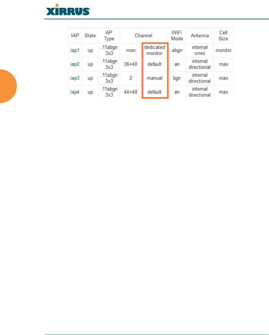
Wireless Array
272 Configuring the Wireless Array
Figure 146. Source of Channel Setting
Arrays have a fast roaming feature, allowing them to maintain sessions for
applications such as voice, even while users cross boundaries between Arrays.
Fast roaming is set up in the Global Settings (IAP) window and is discussed in:
“Understanding Fast Roaming” on page 273
IAPs are configured using the following windows:
“IAP Settings” on page 274
“Global Settings (IAP)” on page 280
“Global Settings .11an” on page 293
“Global Settings .11bgn” on page 298
“Global Settings .11n” on page 304
“Advanced RF Settings” on page 313
“LED Settings” on page 334
“DSCP Mappings” on page 335
“Roaming Assist” on page 336
See Also
IAP Statistics Summary

Wireless Array
Configuring the Wireless Array 273
Understanding Fast Roaming
To maintain sessions for real-time data traffic, such as voice and video, users must
be able to maintain the same IP address through the entire session. With
traditional networks, if a user crosses VLAN or subnet boundaries (i.e., roaming
between domains), a new IP address must be obtained.
Mobile wireless users are likely to cross multiple roaming domains during a
single session (especially wireless users of VoIP phones). Layer 3 roaming allows
a user to maintain the same IP address through an entire real-time data session.
The user may be associated to any of the VLANs defined on the Array. The Layer
3 session is maintained by establishing a tunnel back to the originating Array. You
should decide whether or not to use Layer 3 roaming based on your wired
network design. Layer 3 roaming incurs extra overhead and may result in
additional traffic delays.
Fast Roaming is configured on two pages. To enable the fast roaming options that
you want to make available on your Array, see Step 28 to Step 30 in “Global
Settings (IAP)” on page 280. To choose which of the enabled options are used by
an SSID or Group, see “Procedure for Managing SSIDs” on page 250 (Step 13) or
“Procedure for Managing Groups” on page 266.
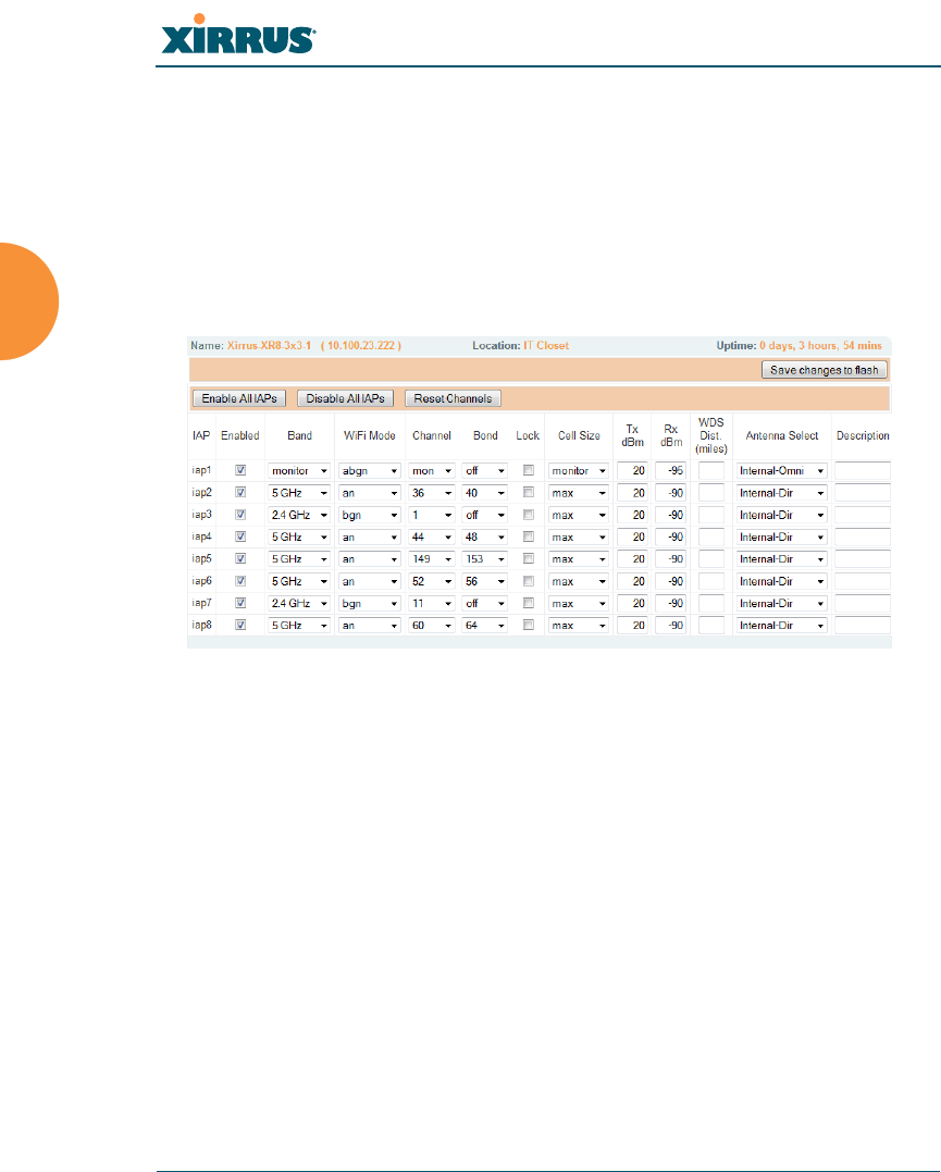
Wireless Array
274 Configuring the Wireless Array
IAP Settings
This window allows you to enable/disable IAPs, define the wireless mode for
each IAP, specify the channel to be used and the cell size for each IAP, lock the
channel selection, establish transmit/receive parameters, select antennas, and
reset channels. Buttons at the bottom of the list allow you to Reset Channels,
Enable All IAPs, or Disable All IAPs. When finished, click Save changes to flash
if you wish to make your changes permanent.
Figure 147. IAP Settings
You may also access this window by clicking on the Array image at the lower left
of the WMI window — click the orange Xirrus logo in the center of the Array. See
“User Interface” on page 88.
Procedure for Auto Configuring IAPs
You can auto-configure channel and cell size of radios by clicking on the Auto
Configure buttons on the relevant WMI page (auto configuration only applies to
enabled radios):
For all radios, go to “Advanced RF Settings” on page 313.
For all 802.11a settings, go to “Global Settings .11an” on page 293.
For all 802.11bg settings, go to “Global Settings .11bgn” on page 298.
For all 802.11n settings, go to “Global Settings .11n” on page 304.

Wireless Array
Configuring the Wireless Array 275
Procedure for Manually Configuring IAPs
1. In the Enabled column, check the box for an IAP to enable it, or uncheck
the box if you want to disable the IAP.
In the Band column, select the wireless band for this IAP from the choices
available in the pull-down menu, either 2.4GHz or 5 GHz. Choosing the
5GHz band will automatically select an adjacent channel for bonding. If
the band displayed is auto, the Band is about to be changed based on a
new Channel selection that you made that requires the change.
One of the IAPs must be set to monitor mode to support Spectrum
Analyzer, Radio Assurance (loopback testing), and Intrusion Detection
features.
2. In the WiFi Mode column, select the IEEE 802.11 wireless mode (or
combination) that you want to allow on this IAP. The drop-down list will
only display the appropriate choices for the selected Band. For example,
the 5 GHz band allows you to select an, a-only, or n-only, while 2.4GHz
also includes 802.11b and 802.11g choices. When you select a WiFi Mode
for an IAP, your selection in the Channel column will be checked to
ensure that it is a valid choice for that WiFi Mode.
By selecting appropriate WiFi Modes for the radios on your Arrays, you
can greatly improve wireless network performance. For example, if you
have 802.11b and 802.11n stations using the same IAP, throughput on that
radio is reduced greatly for the 802.11n stations. By supporting 802.11b
stations only on selected radios in your network, the rest of your 802.11a
or 11n radios will have greatly improved performance. Take care to
ensure that your network provides adequate coverage for the types of
stations that you need to support.
For XN16 Arrays only—
The XN16 allows up to 12 IAPs to operate as 5 GHz — 802.11an radios
concurrently using internal antennas. Do not set Mode to 5 GHz for more
than 12 IAPs unless you are using external antennas. Please contact Xirrus
Customer Support for details.

Wireless Array
276 Configuring the Wireless Array
3. In the Channel column, select the channel you want this IAP to use from
the channels available in the pull-down list. The list shows the channels
available for the IAP selected (depending on which band the IAP is
using). Channels that are shown in color indicate conditions that you
need to keep in mind:
•RED — Usage is not recommended, for example, because of overlap
with neighboring radios.
•YELLOW — The channel has less than optimum separation (some
degree of overlap with neighboring radios).
•GRAY — The channel is already in use.
The channels that are available for assignment to an IAP will differ,
depending on the country of operation. If Country is set to United States
in the Global Settings (IAP) window, then 21 channels are available to
802.11an radios.
4. The Bond column works together with the channel bonding options
selected on the Global Settings .11n page. Also see the discussion of
802.11n bonding in “Channel Bonding” on page 39.
•Channel number — If a channel number appears, then this channel is
already bonded to the listed channel.
•Off — Do not bond his channel to another channel.
•On — Bond this channel to an adjacent channel. The bonded channel
is selected automatically by the Array based on the Channel (Step 3).
The choice of banded channel is static — fixed once the selection is
made.
As mandated by FCC/IC law, Arrays continually scan for signatures of
radar. If such a signature is detected, the Array will switch operation from
conflicting channels to new ones. The Array will switch back to the original
channel after 30 minutes if the channel is clear. If a radio was turned off
because there were no available channels not affected by radar, the Array will
now bring that radio back up after 30 minutes if that channel is clear. The 30
minute time frame complies with FCC/IC regulations.

Wireless Array
Configuring the Wireless Array 277
•+1 — Bond this channel to the next higher channel number. Auto
Channel bonding does not apply. This option is only available for
some of the channels.
•-1 — Bond this channel to the next lower channel number. Auto
Channel bonding does not apply. This option is only available for
some of the channels.
5. Click the Lock check box if you want to lock in your channel selection so
that an autochannel operation (see Advanced RF Settings) can’t change it.
6. In the Cell Size column, select auto to allow the optimal cell size to be
automatically computed (see also, “RF Power & Sensitivity” on page 316).
To set the cell size yourself, choose either small, medium, large, or max to
use the desired pre-configured cell size, or choose manual to define the
wireless cell size manually. If you choose Manual, you must specify the
transmit and receive power — in dB — in the Tx dBm (transmit) and Rx
dBm (receive) fields. The default is max. If you select a value other than
auto, the cell size will not be affected by cell size auto configuration. Note
that ultra low power Tx dBm settings are possible. Values from -15dB to
5dB are provided specifically to help in high density 2.4 GHz
environments.
When other Arrays are within listening range of this one, setting cell sizes
to Auto allows the Array to change cell sizes so that coverage between
cells is maintained. Each cell size is optimized to limit interference
between sectors of other Arrays on the same channel. This eliminates the
need for a network administrator to manually tune the size of each cell
when installing multiple Arrays. In the event that an Array or a radio
goes offline, an adjacent Array can increase its cell size to help
compensate.
The number of users and their applications are major drivers of
bandwidth requirements. The network architect must account for the
number of users within the Array’s cell diameter. In a large office, or if
multiple Arrays are in use, you may choose Small cells to achieve a
higher data rate, since walls and other objects will not define the cells
naturally.
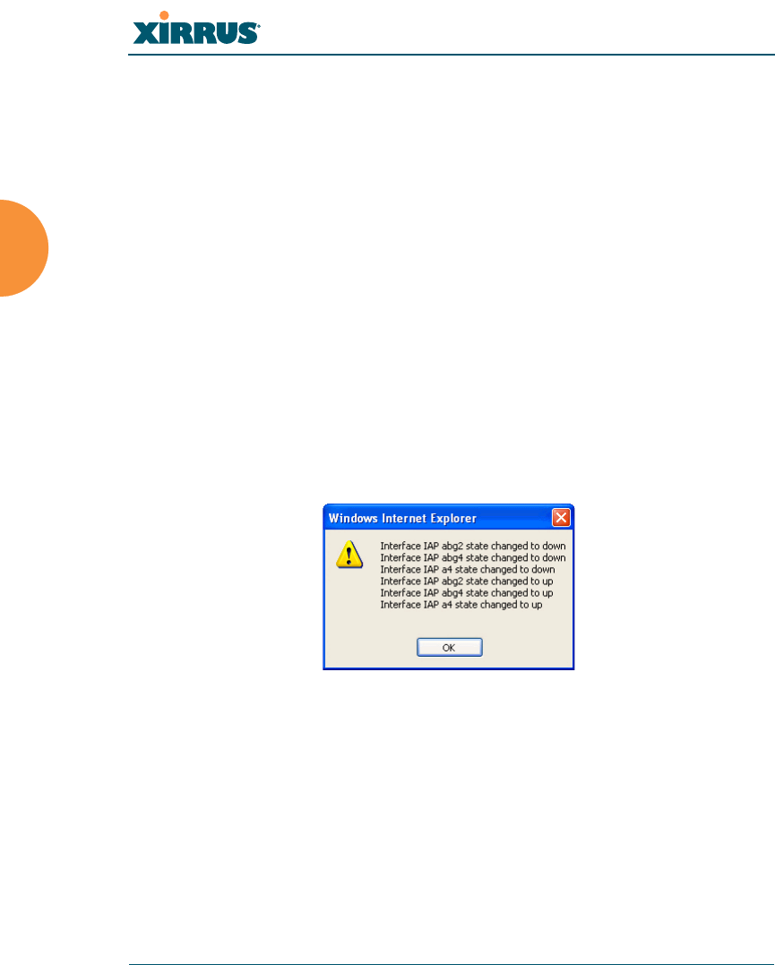
Wireless Array
278 Configuring the Wireless Array
For additional information about cell sizes, go to “Coverage and Capacity
Planning” on page 28.
7. If you are using WDS to provide backhaul over an extended distance, use
WDS Dist. (Miles) to prevent timeout problems associated with long
transmission times. Set the approximate distance in miles between this
IAP and the connected Array in this column. This increases the wait time
for frame transmission accordingly.
8. In the Antenna Select column, choose the antenna you want this radio to
use from the pull-down list. The list of available antennas will be different
(or no choices will be available), depending on the Array model and on
the wireless mode you selected for the IAP.
9. If desired, enter a description for this IAP in the Description field.
10. You may reset all of the enabled IAPs by clicking the Reset Channels
button at the bottom of the list. A message will inform you that all
enabled radios have been taken down and brought back up.
11. Buttons at the bottom of the list allow you to Enable All IAPs or Disable
All IAPs.
12. Click Save changes to flash if you wish to make your changes
permanent.
See Also
Coverage and Capacity Planning
Global Settings (IAP)
Global Settings .11an

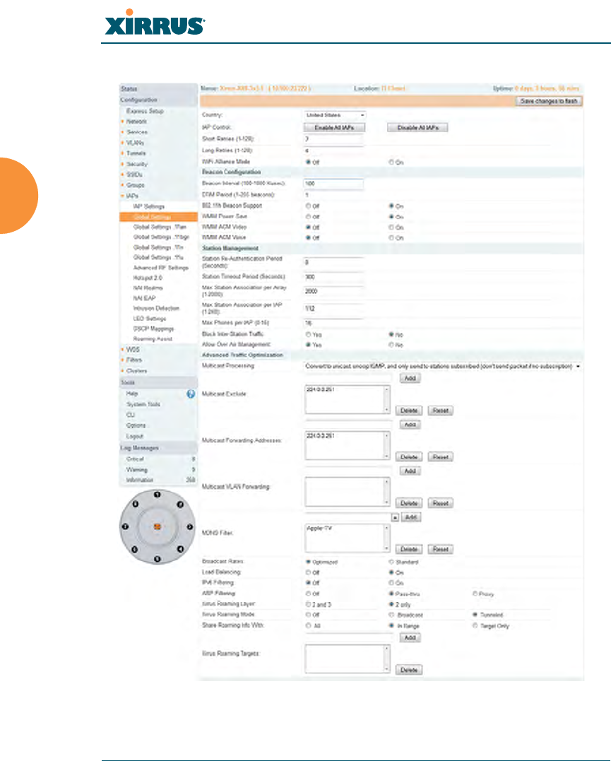
Wireless Array
280 Configuring the Wireless Array
Global Settings (IAP)
Figure 148. Global Settings (IAPs)

Wireless Array
Configuring the Wireless Array 281
This window allows you to establish global IAP settings. Global IAP settings
include enabling or disabling all IAPs (regardless of their operating mode), and
changing settings for beacons, station management, and advanced traffic
optimization — including multicast processing, load balancing, and roaming.
Changes you make on this page are applied to all IAPs, without exception.
Procedure for Configuring Global IAP Settings
1. Country: This is a display-only value. Once a country has been set, it may
not be changed.
The channels that are available for assignment to an IAP will differ,
depending on the country of operation. If Country is set to United States,
then 21 channels are available for 802.11a/n.
If no country is displayed, the channel set defaults to channels and power
levels that are legal worldwide — this set only includes the lower eight 5
GHz channels.
2. IAP Control: Click on the Enable All IAPs button to enable all IAPs for
this Array, or click on the Disable All IAPs button to disable all IAPs.
3. Short Retries: This sets the maximum number of transmission attempts
for a frame, the length of which is less than or equal to the RTS Threshold,
before a failure condition is indicated. The default value is 7. Enter a new
value (1 to 128) in the Short Retry Limit field if you want to increase or
decrease this attribute.
4. Long Retries: This sets the maximum number of transmission attempts
for a frame, the length of which is greater than the RTS Threshold, before
a failure condition is indicated. The default value is 4. Enter a new value
(1 to 128) in the Long Retry Limit field if you want to increase or decrease
this attribute.
Some of the features below, such as Load Balancing, are only available if the
Array’s license includes the Xirrus Advanced RF Performance Manager
(RPM). If a setting is unavailable (grayed out), then your license does not
support the feature. See “About Licensing and Upgrades” on page 361.

Wireless Array
282 Configuring the Wireless Array
5. Wi-Fi Alliance Mode: Set this On if you need Array behavior to conform
completely to Wi-Fi Alliance standards. This mode is normally set to Off.
Beacon Configuration
6. Beacon Interval: When the Array sends a beacon, it includes with it a
beacon interval, which specifies the period of time before it will send the
beacon again. Enter the desired value in the Beacon Interval field,
between 20 and 1000 Kusecs. A Kusec is 1000 microseconds =
1 millisecond. The value you enter here is applied to all IAPs.
7. DTIM Period: A DTIM (Delivery Traffic Indication Message) is a signal
sent as part of a beacon by the Array to a client device in sleep mode,
alerting the device to broadcast traffic awaiting delivery. The DTIM
Period is a multiple of the Beacon Interval, and it determines how often
DTIMs are sent out. By default, the DTIM period is 1, which means that it
is the same as the beacon interval. Enter the desired multiple, between 1
and 255. The value you enter here is applied to all IAPs.
8. 802.11h Beacon Support: This option enables beacons on all of the
Array’s radios to conform to 802.11h requirements, supporting dynamic
frequency selection (DFS) and transmit power control (TPC) to satisfy
regulatory requirements for operation in Europe.
9. WMM Power Save: Click On to enable Wireless Multimedia Power Save
support, as defined in IEEE802.11e. This option saves power and
increases battery life by allowing the client device to doze between
packets to save power, while the Array buffers downlink frames. The
default setting is On.
10. WMM ACM Video: Click On to enable Wireless Multimedia Admission
Control for video traffic. When admission control for video is enabled, the
Array evaluates a video request from a client device against the network
load and channel conditions. If the network is not congested, it accepts
the request and grants the client the medium time for its traffic stream.
Otherwise, it rejects the request. Some clients contain sufficient

Wireless Array
Configuring the Wireless Array 283
intelligence to decide to either delay the traffic stream, associate with a
different AP, or establish a best-effort traffic stream outside the operation
of WMM-Admission Control. The default setting is Off.
11. WMM ACM Voice: Click On to enable Wireless Multimedia Admission
Control for voice calls. When admission control for voice is enabled, the
Array evaluates a voice request from a client device against the network
load and channel conditions. If the network is not congested, it accepts
the request and grants the client the medium time for its call. Otherwise,
it rejects the request. Some clients contain sufficient intelligence to decide
to either delay the traffic stream, associate with a different AP, or establish
a best-effort traffic stream outside the operation of WMM-Admission
Control. The default setting is Off.
Station Management
12. Station Re-Authentication Period: This specifies an interval (in seconds)
for station reauthentications. This is the minimum time period between
station authentication attempts, enforced by the Array. This feature is part
of the Xirrus Advanced RF Security Manager (RSM).
13. Station Timeout Period: Specify a time (in seconds) in this field to define
the timeout period for station associations.
14. Max Station Association per Array: This option allows you to define
how many station associations are allowed per Array (up to 1280 stations
per Array). Note that the Max Station Association per IAP limit (below)
may not be exceeded. If you have an unlicensed Array, this value is set to
1, which simply allows you to test the ability to connect to the Array.
15. Max Station Association per IAP: This defines how many station
associations are allowed per IAP. Note that the SSIDs — SSID
Management window also has a station limit option — Station Limit
(page 254). If both station limits are set, both will be enforced. As soon as
either limit is reached, no new stations can associate until some other
station has terminated its association.

Wireless Array
284 Configuring the Wireless Array
16. Max Phones per IAP: This option allows you to control the maximum
number of phones that are allowed per IAP. The default is set to a
maximum of 16 but you can reduce this number, as desired. Enter a value
in this field between 0 (no phones allowed) and 16.
17. Block Inter-Station Traffic: This option allows you to block or allow
traffic between wireless clients that are associated to the Array. Choose
either Yes (to block traffic) or No (to allow traffic).
18. Allow Over Air Management: Choose Yes to enable management of the
Array via the IAPs, or choose No (recommended) to disable this feature.
Advanced Traffic Optimization
19. Multicast Processing: This sets how multicast traffic is handled.
Multicast traffic can be received by a number of subscribing stations at
the same time, thus saving a great deal of bandwidth. In some of the
options below, the Array uses IGMP snooping to determine the stations
that are subscribed to the multicast traffic. IGMP (Internet Group
Management Protocol) is used to establish and manage the membership
of multicast groups.
Multicast handling options are only applicable to traffic transmitted from
the Array to wireless stations. Select one of the following options:
•Send multicasts unmodified. This is useful when multicast is not
needed because no video or audio streaming is required or when it is
used only for discovering services in the network. Some situations
where you might use this option are:
•for compatibility with ordinary operation, i.e., there is no
optimization or modification of multicast traffic.
•if you have an application where many subscribers need to see
the multicast—a large enough number that it would be less
efficient to convert to unicast and better just to send out multicast
This admission control feature applies only to Spectralink phones. It does not
apply to all VoIP phones in general.

Wireless Array
Configuring the Wireless Array 285
even though it must be sent out at the speed of the slowest
connected station.
An example of a situation that might benefit from the use of this
mode is ghosting all the laptops in a classroom using multicast. One
multicast stream at, say, 6 Mbps is probably more efficient than thirty
unicast streams.
The next three options convert multicast to unicast. Packets are sent
directly to the stations at the best possible data rates. This approach
significantly improves the quality of the voice and video multicast
streams.
•Convert to unicast and send unicast packets to all stations. This
may be useful in link-local multicast situations.
•Convert to unicast, snoop IGMP, and only send to stations
subscribed (send as multicast if no subscription). This option is
useful when you need to stream voice or video multicast traffic to all
stations, but some stations are capable of subscribing to multicast
groups while other stations are not. The stations that do not subscribe
will not benefit from conversion to unicast; their video or voice
quality may be compromised.
•Convert to unicast, snoop IGMP, and only send to stations
subscribed (don't send packet if no subscription). This option is
useful in well controlled environments when you need to stream
voice or video multicast traffic only to stations that are capable of
subscribing to multicast groups and there is no need for the rest of the
stations to receive the data stream.
20. Multicast Exclude: This is a list of multicast IP addresses that will not be
subject to multicast-to-unicast conversion. This list is useful on networks
where applications such as those using multicast Domain Name System
(mDNS) are in use. For example, Apple Bonjour finds local network
devices such as printers or other computers using mDNS. By default, the
list contains the IPv4 multicast address for Apple Bonjour mDNS:
224.0.0.251.

Wireless Array
286 Configuring the Wireless Array
To add a new IP address to the list, type it in the top field and click the
Add button to its right. You may only enter IP addresses—host names are
not allowed. This is because mDNS is a link local multicast address, and
does not require IGMP to the gateway.
To remove an entry, select it in the list and click Delete. To remove all
entries from the list, click Reset.
21. Multicast Forwarding
Multicast Forwarding is a Xirrus feature that forwards selected multicast
traffic between wired VLANs and wireless SSIDs. For example, Apple
devices use mDNS to advertise and find services, using local network
multicasts that are not routed. This creates an issue when you are using
Apple devices on the Wireless LAN, and have other devices that provide
services connected on the wired infrastructure in a different VLAN, for
example, printers and AppleTV devices. One way to address this issue is
to set up multicast forwarding between the wireless SSID and the wired
VLAN. This requires the wired VLAN to be trunked to the Array. Once
configured correctly, mDNS traffic will be forwarded from the specified
wireless network(s) to the specified wired VLANs and vice-versa, subject
to any mDNS service filtering defined (Step 23).
Use multicast forwarding together with multicast VLAN forwarding
(Step 22) and mDNS filtering (Step 23) to make services available across
VLANs as follows:
•In Multicast Forwarding Addresses, enter a list of multicast
addresses that you want forwarded, for example, 224.0.0.251 (the
multicast address for Bonjour).
•In Multicast VLAN Forwarding, enter a list of VLANs that
participate in the multicast forwarding.
•In MDNS Filter, specify the mDNS service types that are allowed to
be forwarded.
•If you leave this field blank, then there is no filter, and mDNS
packets for all service types are passed.

Wireless Array
Configuring the Wireless Array 287
•If you enter service types, then this acts as an allow filter, and
mDNS packets are passed only for the listed service types.
Note that mDNS filtering may be used to filter the mDNS packet
types that are forwarded within the same VLAN. Also, in conjunction
with multicast forwarding, it may be used to filter the mDNS packet
types that are forwarded across configured VLANs.
After you have entered these settings, when multicast packets arrive from
the wired network from one of the Multicast Forwarding Addresses on
any VLAN specified in Multicast VLAN Forwarding, they are forwarded
to the corresponding wireless SSID for that VLAN. .
Multicast packets coming in from the wireless network on an SSID tied to
one of the specified VLANs and matching one of the Multicast
Forwarding Addresses are forwarded to the specified VLANs on the
wired network.
No modifications are made to the forwarded packets – they are just
forwarded between specified VLANs and associated SSIDs.
To specify Multicast Forwarding Addresses: enter each IP address in the
top field and click the Add button to its right. You may only enter IPv4
multicast addresses - host names are not allowed. To remove an entry,
select it in the list and click Delete. To remove all entries from the list,
click Reset.
Xirrus strongly recommends the use of MDNS Filters (Step 23) when using
multicast forwarding. Only allow required services to be forwarded.
Carefully monitor results, as forwarding may flood your network with
multicast traffic. Experience has shown Bonjour devices to be very chatty.
Also note that since this is link local multicast traffic, it will be sent to every
wired port in the VLAN, as IGMP snooping does not work with link local
multicast addresses.

Wireless Array
288 Configuring the Wireless Array
22. Multicast VLAN Forwarding: This is a list of VLANs that participate in
the multicast forwarding. Please see the description of multicast
forwarding in Step 21 above.
To add a new VLAN to the list, enter its number or name in the top field
and click the Add button to its right. You may enter multiple VLANs at
once, separated by a space. To remove an entry, select it in the list and
click Delete. To remove all entries from the list, click Reset.
These VLANs must be trunked to the Array from the LAN switch, and be
defined on the Array. See “VLAN Management” on page 201 and “SSID
Management” on page 249.
The VLANs you enter must be explicitly defined (see “VLANs” on
page 199) in order to participate in multicast forwarding. In fact, the Array
discards packets from undefined VLANs.
Note that Multicast Forwarding and mDNS Filtering capabilities also work
if both devices are wireless. For example, let’s say that AppleTV is using
wireless to connect to an SSID that is associated with VLAN 56, and the
wireless client is on an SSID that is associated with VLAN 58. Normally the
wireless client would not be able to use Bonjour to discover the AppleTV
because they are on separate VLANs. But if you add 224.0.0.251 to the
Multicast Forwarding Addresses, then add VLANs 56 and 58 to the
Multicast VLAN Forwarding list, then the wireless client will be able to
discover the AppleTV. In this same scenario you could add AppleTV to the
MDNS Filter list so that only MDNS packets for the AppleTV service type
would be forwarded between VLANs 56 and 58.
Note that all the VLANs that you add to this list do not have to be associated
with SSIDs. As an example, say that AppleTV is on the wired network on
VLAN 56, while the wireless device is connected to an SSID that is
associated to VLAN 58. In this case, VLAN 56 and 58 need to be defined on
the Array but only VLAN 58 needs to be associated to a SSID.

Wireless Array
Configuring the Wireless Array 289
23. MDNS Filter: There are many different types of services that may be
specified in multicast query and response packets. The mDNS filters let
you restrict forwarding, so that multicast packets are forwarded only for
the services that you explicitly specify. This list may be used to restrict the
amount of Apple Bonjour multicast traffic forwarding. For example, you
may restrict forwarding to just AppleTV and printing services. Please see
the description of multicast forwarding in Step 21 above.
The MDNS Filter operates as follows:
•If you leave this field blank, then there is no filter, and mDNS
packets for all service types are passed.
•If you enter service types, then this acts as an allow filter, and
mDNS packets are passed only for the listed service types.
To add an mDNS packet type to the list of packets that may be forwarded,
select it from the drop-down list in the top field and click the Add button
to its right. The drop-down list offers packet types such as AirTunes,
Apple-TV, iChat, iPhoto, iTunes, iTunes-Home-Sharing, Internet-
Printing, Mobile-Device-Sync, and Secure-Telnet.
For example, to allow mirroring of an iPad on an Apple-TV, select Apple-
TV.
You may define your own type if you do not see the service you want in
the drop-down list. Simply enter the mDNS service name that you would
like to allow through. Custom mDNS packet types must be prefixed with
an underscore, e.g., _airvideoserver.
To remove an entry, select it in the list and click Delete. To remove all
entries from the list, click Reset.
24. Broadcast Rates: This changes the rates of broadcast traffic sent by the
Array (including beacons). When set to Optimized, each broadcast or
multicast packet that is transmitted on each radio is sent at the lowest
transmit rate used by any client associated to that radio at that time. This
results in each IAP broadcasting at the highest Array TX data rate that can
be heard by all associated stations, improving system performance. The
rate is determined dynamically to ensure the best broadcast/multicast

Wireless Array
290 Configuring the Wireless Array
performance possible. The benefit is dramatic. Consider a properly
designed network (having -70db or better everywhere), where virtually
every client should have a 54Mbps connection. In this case, broadcasts
and multicasts will all go out at 54Mbps vs. the standard rate. Thus, with
broadcast rate optimization on, broadcasts and multicasts use between
2% and 10% of the bandwidth that they would in Standard mode.
When set to Standard (the default), broadcasts are sent out at the lowest
basic rate only — 6 Mbps for 5GHz clients, or 1 Mbps for 2.4GHz clients.
The option you select here is applied to all IAPs.
25. Load Balancing: The Xirrus Wireless Array supports an automatic load
balancing feature designed to distribute wireless stations across multiple
radios rather than having stations associate to the closest radios with the
strongest signal strength, as they normally would. In wireless networks,
the station decides to which radio it will associate. The Array cannot
actually force load balancing, however the Array can “encourage”
stations to associate in a more uniform fashion across all of the radios of
the Array. This option enables or disables active load balancing between
the Array IAPs. For an in-depth discussion, see the Xirrus Station Load
Balancing Application Note in the Xirrus Resource Center.
If you select On and an IAP is overloaded, that IAP will send an “AP
Full” message in response to Probe, Association, or Authentication
requests. This prevents determined clients from forcing their way onto
overloaded IAPs. Note that some clients are so determined to associate to
a particular IAP that they will not try to associate to another IAP, and thus
they never get on the network.
Choose Off to disable load balancing.
26. ARP Filtering: Address Resolution Protocol finds the MAC address of a
device with a given IP address by sending out a broadcast message
requesting this information. ARP filtering allows you to reduce the
proliferation of ARP messages by restricting how they are forwarded
across the network.
You may select from the following options for handling ARP requests:

Wireless Array
Configuring the Wireless Array 291
•Off: ARP filtering is disabled. ARP requests are broadcast to radios
that have stations associated to them.
•Pass-thru: The Array forwards the ARP request. It passes along only
ARP messages that target the stations that are associated to it. This is
the default value.
•Proxy: The Array replies on behalf of the stations that are associated
to it. The ARP request is not broadcast to the stations.
Note that the Array has a broadcast optimization feature that is always on
(it is not configurable). Broadcast optimization restricts all broadcast
packets (not just ARP broadcasts) to only those radios that need to
forward them. For instance, if a broadcast comes in from VLAN 10, and
there are no VLAN 10 users on a radio, then that radio will not send out
that broadcast. This increases available air time for other traffic.
27. IPv6 Filtering: this setting allows blocking of IPv6 traffic which may be a
concern for IT managers. The Xirrus Array currently bridges IPv6 traffic.
Set IPv6 filtering On if you wish to prevent the forwarding of IPv6
packets through the Array in both directions—wired network to wireless
and wireless network to wired. The default is Off.
28. Xirrus Roaming Layer: Select whether to enable roaming capabilities
between IAPs or Arrays at Layer 2 and 3, or at Layer 2 only. Depending
on your wired network, you may wish to allow fast roaming at Layer 3.
This may result in delayed traffic.
29. Xirrus Roaming Mode: This feature utilizes the Xirrus Roaming Protocol
(XRP) ensuring fast and seamless roaming capabilities between IAPs or
Arrays at Layer 2 and Layer 3 (as specified in Step 30), while maintaining
security. Fast roaming eliminates long delays for re-authentication, thus
supporting time-sensitive applications such as Voice over Wi-Fi (see
“Understanding Fast Roaming” on page 273 for a discussion of this
feature). XRP uses a discovery process to identify other Xirrus Arrays as
fast roaming targets. This process has two modes:
•Broadcast — the Array uses a broadcast technique to discover other
Arrays that may be targets for fast roaming.

Wireless Array
292 Configuring the Wireless Array
•Tunneled — in this Layer 3 technique, fast roaming target Arrays
must be explicitly specified.
To enable fast roaming, choose Broadcast or Tu n n e l e d , and set additional
fast roaming attributes (Step 30). To disable fast roaming, choose Off. If
you enable Fast Roaming, the following ports cannot be blocked:
•Port 22610 — reserved for Layer 2 roaming using UDP to share PMK
information between Arrays.
•Ports 15000 to 17999 — reserved for Layer 3 roaming (tunneling
between subnets).
30. Share Roaming Info With: Three options allow your Array to share
roaming information with all Arrays; just with those that are within
range; or with specifically targeted Arrays. Choose either All, In Range
or Tar get Only, respectively.
a. Xirrus Roaming Targets: If you chose Targ e t Onl y, use this option to
add target MAC addresses. Enter the MAC address of each target
Array, then click on Add (add as many targets as you like). To find a
target’s MAC address, open the Array Info window on the target
Array and look for IAP MAC Range, then use the starting address of
this range.
To delete a target, select it from the list, then click Delete.
See Also
Coverage and Capacity Planning
Global Settings .11an
Global Settings .11bgn
Global Settings .11n
Advanced RF Settings
IAPs
IAP Statistics Summary
LED Settings
IAP Settings
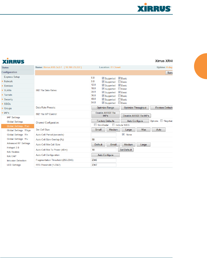
Wireless Array
Configuring the Wireless Array 293
Global Settings .11an
This window allows you to establish global 802.11a IAP settings. These settings
include defining which 802.11a data rates are supported, enabling or disabling all
802.11an IAPs, auto-configuration of channel allocations for all 802.11an IAPs,
and specifying the fragmentation and RTS thresholds for all 802.11an IAPs.
Figure 149. Global Settings .11an
Procedure for Configuring Global 802.11an IAP Settings
1. 802.11a Data Rates: The Array allows you to define which data rates are
supported for all 802.11an radios. Select (or deselect) data rates by
clicking in the corresponding Supported and Basic data rate check boxes.
•Basic Rate — a wireless station (client) must support this rate in order
to associate.
•Supported Rate — data rates that can be used to transmit to clients.
2. Data Rate Presets: The Wireless Array can optimize your 802.11a data
rates automatically, based on range or throughput. Click Optimize Range

Wireless Array
294 Configuring the Wireless Array
to optimize data rates based on range, or click Optimize Throughput to
optimize data rates based on throughput. The Restore Defaults button
will take you back to the factory default rate settings.
3. 802.11a IAP Control: Click Enable 802.11a IAPs to enable all 802.11an
IAPs for this Array, or click Disable 802.11a IAPs to disable all 802.11an
IAPs.
4. Channel Configuration: Click Auto Configure to instruct the Array to
determine the best channel allocation settings for each 802.11an IAP and
select the channel automatically, based on changes in the environment.
This is the recommended method for 802.11a channel allocation (see “RF
Spectrum Management” on page 318).
Click Factory Defaults if you wish to instruct the Array to return all IAPs
to their factory preset channels. As of release 6.3, Arrays no longer all use
the same factory preset values for channel assignments. Instead, if the
Array has been deployed for a while and already has data from the
spectrum analyzer and Xirrus Roaming Protocol about channel usage on
neighboring arrays, it performs a quick auto channel using that
information (without doing a full RF scan) to make an intelligent choice
of channel assignments. If the Array has been rebooted and has no saved
configuration or is just being deployed for the first time, it has no prior
data about its RF environment. In this case, it will pick a set of compatible
channel assignments at random.
Some of the features below, such as Auto Configure for Cell Size and
Channel Configuration, are only available if the Array’s license includes the
Xirrus Advanced RF Performance Manager (RPM). If a setting is
unavailable (grayed out), then your license does not support the feature.
Please see “About Licensing and Upgrades” on page 361.
On the XR500 and XR-1000 Series Arrays, the Factory Defaults button
will not restore iap1 to monitor mode. You will need to restore this setting
manually. Also, you may need to set Timeshare Mode again - see “RF
Monitor” on page 314.
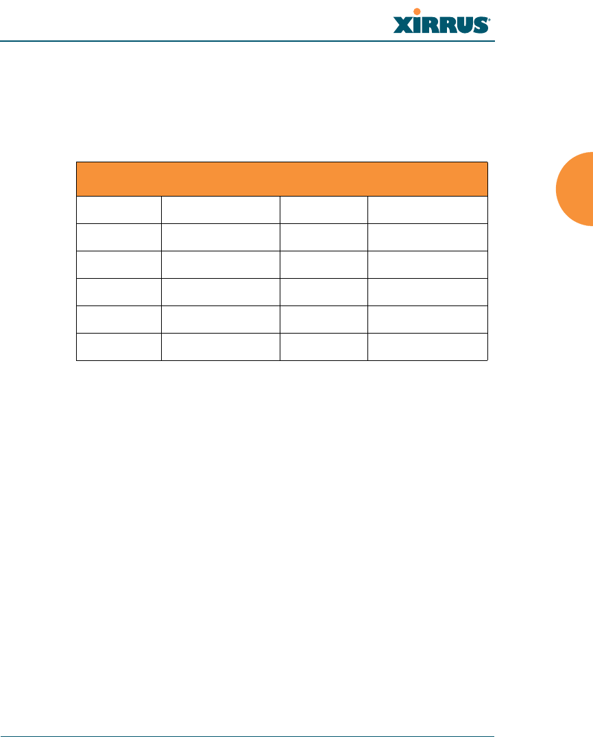
Wireless Array
Configuring the Wireless Array 295
The following options may be selected for auto configuration:
•Non-Radar: give preference to channels that are not required to use
dynamic frequency selection (DFS) to avoid communicating in the
same frequency range as some radar (also see Step 8 on page 282).
•Negotiate: negotiate air-time with other Arrays before performing a
full scan.
•Full Scan: perform a full traffic scan on all channels on all IAPs to
determine the best channel allocation.
•Include WDS: automatically assign 5GHz to WDS client links.
5. Set Cell Size: Cell Size may be set globally for all 802.11an IAPs to Auto,
Large, Medium, Small, or Max using the buttons.
Channels Required to Use DFS Radar Avoidance in USA
36+40 Non-radar 116+120 DFS required
44+48 Non-radar 124+128 DFS required
52+56 DFS required 132+136 DFS required
60+64 DFS required 149+153 Non-radar
100+104 DFS required 157+161 Non-radar
108+112 DFS required
To use the Auto Cell Size feature, the following additional settings are
required:
RF Monitor Mode must be turned On. See “RF Monitor” on page 314
One of the radios must be in monitor mode with the default RxdBm setting
of -95, and all other IAPs that will use Auto Cell must have Cell Size set to
auto. See “Procedure for Manually Configuring IAPs” on page 275.

Wireless Array
296 Configuring the Wireless Array
For an overview of RF power and cell size settings, please see “RF Power
& Sensitivity” on page 316, “Capacity and Cell Sizes” on page 30, and
“Fine Tuning Cell Sizes” on page 31.
6. Auto Cell Period (seconds): You may set up auto-configuration to run
periodically, readjusting optimal cell sizes for the current conditions.
Enter a number of seconds to specify how often auto-configuration will
run. If you select None, then auto-configuration of cell sizing will not be
run periodically. You do not need to run Auto Cell often unless there are a
lot of changes in the environment. If the RF environment is changing
often, running Auto Cell every twenty-four hours (86400 seconds) should
be sufficient). The default value is None.
7. Auto Cell Size Overlap (%): Enter the percentage of cell overlap that will
be allowed when the Array is determining automatic cell sizes. For 100%
overlap, the power is adjusted such that neighboring Arrays that hear
each other best will hear each other at -70dB. For 0% overlap, that number
is -90dB. The default value is 50%.
8. Auto Cell Min Cell Size: Use this setting if you wish to set the minimum
cell size that Auto Cell may assign. The values are Default, Large,
Medium, or Small.
9. Auto Cell Min Tx Power (dBm): Enter the minimum transmit power that
the Array can assign to a radio when adjusting automatic cell sizes. The
default value is 10.
10. Auto Cell Configuration: Click this button to instruct the Array to
determine and set the best cell size for each 802.11an IAP whose Cell Size
is auto on the IAP Settings window, based on changes in the
environment. This is the recommended method for setting cell size. You
may look at the Tx and Rx values on the IAP Settings window to view the
cell size settings that were applied.
11. Fragmentation Threshold: This is the maximum size for directed data
packets transmitted over the 802.11an radio. Larger frames fragment into
several packets, their maximum size defined by the value you enter here.

Wireless Array
Configuring the Wireless Array 297
Smaller fragmentation numbers can help to “squeeze” packets through in
noisy environments. Enter the desired Fragmentation Threshold value in
this field, between 256 and 2346.
12. RTS Threshold: The RTS (Request To Send) Threshold specifies the
packet size. Packets larger than the RTS threshold will use CTS/RTS prior
to transmitting the packet — useful for larger packets to help ensure the
success of their transmission. Enter a value between 1 and 2347.
See Also
Coverage and Capacity Planning
Global Settings (IAP)
Global Settings .11bgn
Global Settings .11n
IAPs
IAP Statistics Summary
Advanced RF Settings
IAP Settings
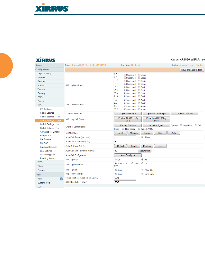
Wireless Array
298 Configuring the Wireless Array
Global Settings .11bgn
This window allows you to establish global 802.11b/g IAP settings. These settings
include defining which 802.11b and 802.11g data rates are supported, enabling or
disabling all 802.11b/g IAPs, auto-configuring 802.11b/g IAP channel allocations,
and specifying the fragmentation and RTS thresholds for all 802.11b/g IAPs.
Figure 150. Global Settings .11bgn
Some of the features below, such as Auto Configure for Cell Size and
Channel Configuration, are only available if the Array’s license includes the
Xirrus Advanced RF Performance Manager (RPM). If a setting is
unavailable (grayed out), then your license does not support the feature.
Please see “About Licensing and Upgrades” on page 361.

Wireless Array
Configuring the Wireless Array 299
Procedure for Configuring Global 802.11b/g IAP Settings
1. 802.11g Data Rates: The Array allows you to define which data rates are
supported for all 802.11g radios. Select (or deselect) 11g data rates by
clicking in the corresponding Supported and Basic data rate check boxes.
•Basic Rate — a wireless station (client) must support this rate in
order to associate.
•Supported Rate — data rates that can be used to transmit to
clients.
2. 802.11b Data Rates: This task is similar to Step 1, but these data rates
apply only to 802.11b IAPs.
3. Data Rate Presets: The Wireless Array can optimize your 802.11b/g data
rates automatically, based on range or throughput. Click Optimize Range
button to optimize data rates based on range, or click on the Optimize
Throughput to optimize data rates based on throughput. Restore
Defaults will take you back to the factory default rate settings.
4. 802.11b/g IAP Control: Click Enable All 802.11b/g IAPs to enable all
802.11b/g IAPs for this Array, or click Disable All 802.11b/g IAPs to
disable them.
5. Channel Configuration: Click Auto Configure to instruct the Array to
determine the best channel allocation settings for each 802.11b/g IAP and
select the channel automatically, based on changes in the environment.
This is the recommended method for channel allocation (see “RF
Spectrum Management” on page 318).
Click Factory Defaults if you wish to instruct the Array to return all IAPs
to their factory preset channels. As of release 6.3, Arrays no longer all use
the same factory preset values for channel assignments. Instead, if the
Array has been deployed for a while and already has data from the
spectrum analyzer and Xirrus Roaming Protocol about channel usage on
neighboring arrays, it performs a quick auto channel using that
information (without doing a full RF scan) to make an intelligent choice
of channel assignments. If the Array has been rebooted and has no saved
configuration or is just being deployed for the first time, it has no prior

Wireless Array
300 Configuring the Wireless Array
data about its RF environment. In this case, it will pick a set of compatible
channel assignments at random.
The following options may be selected for auto configuration:
•Negotiate: negotiate air-time with other Arrays before performing a
full scan.
•Full Scan: perform a full traffic scan on all channels on all IAPs to
determine the best channel allocation.
•Non-Radar: give preference to channels without radar-detect. See
table in “Procedure for Configuring Global 802.11an IAP Settings” on
page 293.
•Include WDS: automatically assign 5GHz to WDS client links.
6. Set Cell Size/ Autoconfigure: Cell Size may be set globally for all
802.11b/g IAPs to auto, large, medium, small, or max using the drop
down menu.
For an overview of RF power and cell size settings, please see “RF Power
& Sensitivity” on page 316, “Capacity and Cell Sizes” on page 30, and
“Fine Tuning Cell Sizes” on page 31.
On the XR500 and XR-1000 Series Arrays, the Factory Defaults button
will not restore iap1 to monitor mode. You will need to restore this setting
manually. Also, you may need to set Timeshare Mode again - see “RF
Monitor” on page 314.
To use the Auto Cell Size feature, the following additional settings are
required:
RF Monitor Mode must be turned On. See “RF Monitor” on page 314
One of the radios must be in monitor mode with the default RxdBm setting
of -95, and all other IAPs that will use Auto Cell must have Cell Size set to
auto. See “Procedure for Manually Configuring IAPs” on page 275.

Wireless Array
Configuring the Wireless Array 301
7. Auto Cell Period (seconds): You may set up auto-configuration to run
periodically, readjusting optimal cell sizes for the current conditions.
Enter a number of seconds to specify how often auto-configuration will
run. If you select None, then auto-configuration of cell sizing will not be
run periodically. You do not need to run Auto Cell often unless there are a
lot of changes in the environment. If the RF environment is changing
often, running Auto Cell every twenty-four hours (86400 seconds) should
be sufficient). The default value is None.
8. Auto Cell Size Overlap (%): Enter the percentage of cell overlap that will
be allowed when the Array is determining automatic cell sizes. For 100%
overlap, the power is adjusted such that neighboring Arrays that hear
each other best will hear each other at -70dB. For 0% overlap, that number
is -90dB. The default value is 50%.
9. Auto Cell Min Cell Size: Use this setting if you wish to set the minimum
cell size that Auto Cell may assign. The values are Default, Large,
Medium, or Small.
10. Auto Cell Min Tx Power (dBm): Enter the minimum transmit power that
the Array can assign to a radio when adjusting automatic cell sizes. The
default value is 10.
11. Auto Cell Configuration: Click Auto Configure to instruct the Array to
determine and set the best cell size for each enabled 802.11b/g IAP whose
Cell Size is auto on the IAP Settings window, based on changes in the
environment. This is the recommended method for setting cell size. You
may look at the Tx and Rx values on the IAP Settings window to view the
cell size settings that were applied.
12. 802.11g Only: Choose On to restrict use to 802.11g mode only. In this
mode, no 802.11b rates are transmitted. Stations that only support 802.11b
will not be able to associate.
13. 802.11g Protection: You should select Auto CTS or Auto RTS to provide
automatic protection for all 802.11g radios in mixed networks (802.11
b and g). You may select Off to disable this feature, but this is not
recommended. Protection allows 802.11g stations to share an IAP with

Wireless Array
302 Configuring the Wireless Array
older, slower 802.11b stations. Protection avoids collisions by preventing
802.11b and 802.11g stations from transmitting simultaneously. When
Auto CTS or Auto RTS is enabled and any 802.11b station is associated to
the IAP, additional frames are sent to gain access to the wireless network.
•Auto CTS requires 802.11g stations to send a slow Clear To Send
frame that locks out other stations. Automatic protection reduces
802.11g throughput when 802.11b stations are present — Auto CTS
adds less overhead than Auto RTS. The default value is Auto CTS.
•With Auto RTS, 802.11g stations reserve the wireless media using a
Request To Send/Clear To Send cycle. This mode is useful when you
have dispersed nodes. It was originally used in 802.11b only
networks to avoid collisions from “hidden nodes” — nodes that are so
widely dispersed that they can hear the Array, but not each other.
When there are no 11b stations associated and an auto-protection mode is
enabled, the Array will not send the extra frames, thus avoiding
unnecessary overhead.
14. 802.11g Slot: Choose Auto to instruct the Array to manage the 802.11g
slot times automatically, or choose Short Only. Xirrus recommends using
Auto for this setting, especially if 802.11b devices are present.
15. 802.11b Preamble: The preamble contains information that the Array and
client devices need when sending and receiving packets. All compliant
802.11b systems have to support the long preamble. A short preamble
improves the efficiency of a network's throughput when transmitting
special data, such as voice, VoIP (Voice-over IP) and streaming video.
Select Auto to instruct the Array to manage the preamble (long and short)
automatically, or choose Long Only.
16. Fragmentation Threshold: This is the maximum size for directed data
packets transmitted over the 802.11b/g IAP. Larger frames fragment into
several packets, their maximum size defined by the value you enter here.
Enter the desired Fragmentation Threshold value, between 256 and 2346.

Wireless Array
Configuring the Wireless Array 303
17. RTS Threshold: The RTS (Request To Send) Threshold specifies the
packet size. Packets larger than the RTS threshold will use CTS/RTS prior
to transmitting the packet — useful for larger packets to help ensure the
success of their transmission. Enter a value between 1 and 2347.
See Also
Coverage and Capacity Planning
Global Settings (IAP)
Global Settings .11an
Global Settings .11n
Advanced RF Settings
LED Settings
IAP Settings
IAP Statistics Summary
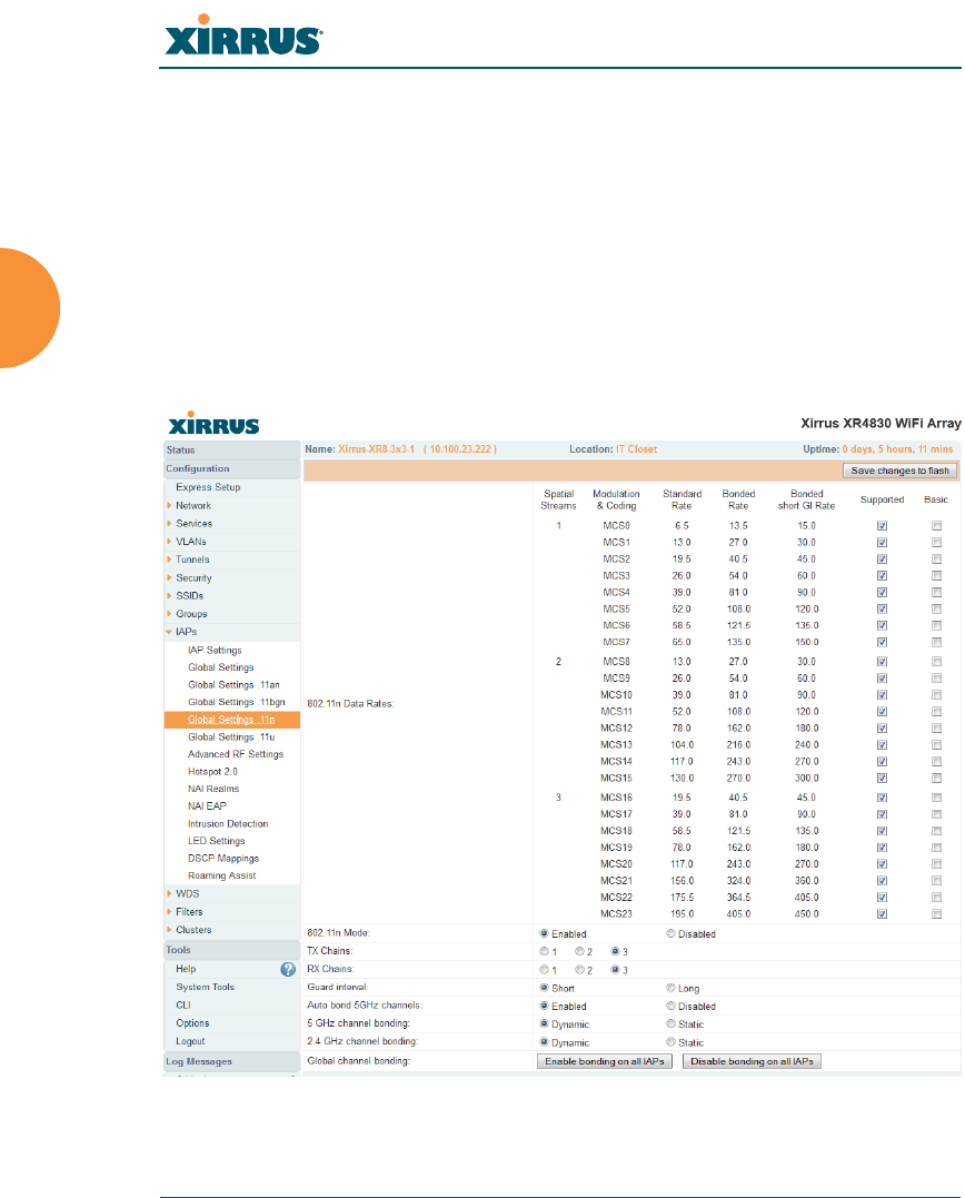
Wireless Array
304 Configuring the Wireless Array
Global Settings .11n
This window allows you to establish global 802.11n IAP settings. These settings
include enabling or disabling 802.11n mode for the entire Array, specifying the
number of transmit and receive chains (data stream) used for spatial
multiplexing, setting a short or standard guard interval, auto-configuring channel
bonding, and specifying whether auto-configured channel bonding will be static
or dynamic.
Before changing your settings for 802.11n, please read the discussion in “IEEE
802.11n Deployment Considerations” on page 35.
Figure 151. Global Settings .11n

Wireless Array
Configuring the Wireless Array 305
Procedure for Configuring Global 802.11n IAP Settings
1. 802.11n Data Rates: The Array allows you to define which data rates are
supported for all 802.11n radios. Select (or deselect) 11n data rates by
clicking in the corresponding Supported and Basic data rate check boxes.
•Basic Rate — a wireless station (client) must support this rate in
order to associate.
•Supported Rate — data rates that can be used to transmit to
clients.
2. 802.11n Mode: Select Enabled to allow the Array to operate in 802.11n
mode. Use of this mode is controlled by the Array’s license key. The key
must include 802.11n capability, or you will not be able to enable this
mode. See “License” on page 107 to view the features supported by your
license key. Contact Xirrus Customer support for questions about your
license.
If you select Disabled, then 802.11n operation is disabled on the Array.
For XN Arrays, IAPs abgn1 though abgn4 will operate in 802.11abg
mode; the 802.11a/n IAPs will operate in 802.11a mode.
3. TX Chains: Select the number of separate data streams transmitted by the
antennas of each IAP. The default is 3. See “Multiple Data Streams —
Spatial Multiplexing” on page 38.
4. RX Chains: Select the number of separate data streams received by the
antennas of each IAP. This number should be greater than or equal to TX
Chains. The default is 3. See “Multiple Data Streams — Spatial
Multiplexing” on page 38.
5. Guard interval: Select Short to increase the data transmission rate by
decreasing wait intervals in signal transmission. Select Long to use the
standard interval. The default is Short. See “Short Guard Interval” on
page 40.
802.11n operation is allowed only if the Array’s license includes this feature.
Please see “About Licensing and Upgrades” on page 361.

Wireless Array
306 Configuring the Wireless Array
6. Auto bond 5 GHz channels: Select Enabled to use Channel Bonding on
5 GHz channels and automatically select the best channels for bonding.
The default is Enabled. See “Channel Bonding” on page 39.
7. 5 GHz channel bonding: Select Dynamic to have auto-configuration for
bonded 5 GHz channels be automatically updated as conditions change.
For example, if there are too many clients to be supported by a bonded
channel, dynamic mode will automatically break the bonded channel into
two channels. Select Static to have the bonded channels remain the same
once they are selected. The Dynamic option is only available when Auto
bond 5 GHz channels is enabled. The default is Dynamic. See “Channel
Bonding” on page 39.
8. 2.4 GHz channel bonding: Select Dynamic to have auto-configuration
for bonded 2.4 GHz channels be automatically updated as conditions
change. Select Static to have the bonded channels remain the same once
they are selected. The default is Dynamic. See “Channel Bonding” on
page 39.
9. Global channel bonding: These buttons allow you to turn channel
bonding on or off for all IAPs in one step. The effect of using one of these
buttons will be shown if you go to the IAP Settings window and look at
the Bond column. Clicking Enable bonding on all IAPs causes all IAPs
to be bonded to their auto-bonding channel immediately, if appropriate.
For example, an IAP will not be bonded if it is set to monitor mode, and
2.4 GHz radios will not be bonded. Click Disable bonding on all IAPs to
turn off bonding on all IAPs immediately. See “Channel Bonding” on
page 39. Settings in Step 7 and Step 8 are independent of global channel
bonding.

Wireless Array
Configuring the Wireless Array 307
Global Settings .11u
Understanding 802.11u
As the number of access points available in public venues increases, mobile
devices users have a harder time distinguishing usable SSIDs from the tens, if not
hundreds of access points visible. Using the 802.11u protocol, access points may
broadcast information about the services and access that they offer and to respond
to queries for additional information related to the facilities that the downstream
service network provides.
The type of information broadcast or available from 802.11u-compliant access
points includes:
Access Network Type. Indicates the type of network available. For
example: public or private, free or charged, etc.
Internet Connectivity. Indicates whether the network provides Internet
connectivity.
Authentication. Indicates whether additional authentication steps will be
required to use the network as well as the network authentication types
that are in use.
Venue Information. The type and name of the location where the access
point is found.
Identification. A globally unique identification for the access point.
IPv4/IPv6 Addressing. Indicate the type of IP addressing (IPv4 and/or
IPv6) and NATing that is performed by the network.
Roaming Consortium. The service network may be connected to one or
more roaming providers, called consortia, that allow access points from
multiple service providers to be used transparently through a single paid
service. The access point may advertise multiple consortia to mobile
devices.
Domain Names. A list of domain names to which the mobile user may
end up belonging based on authentication credentials used.
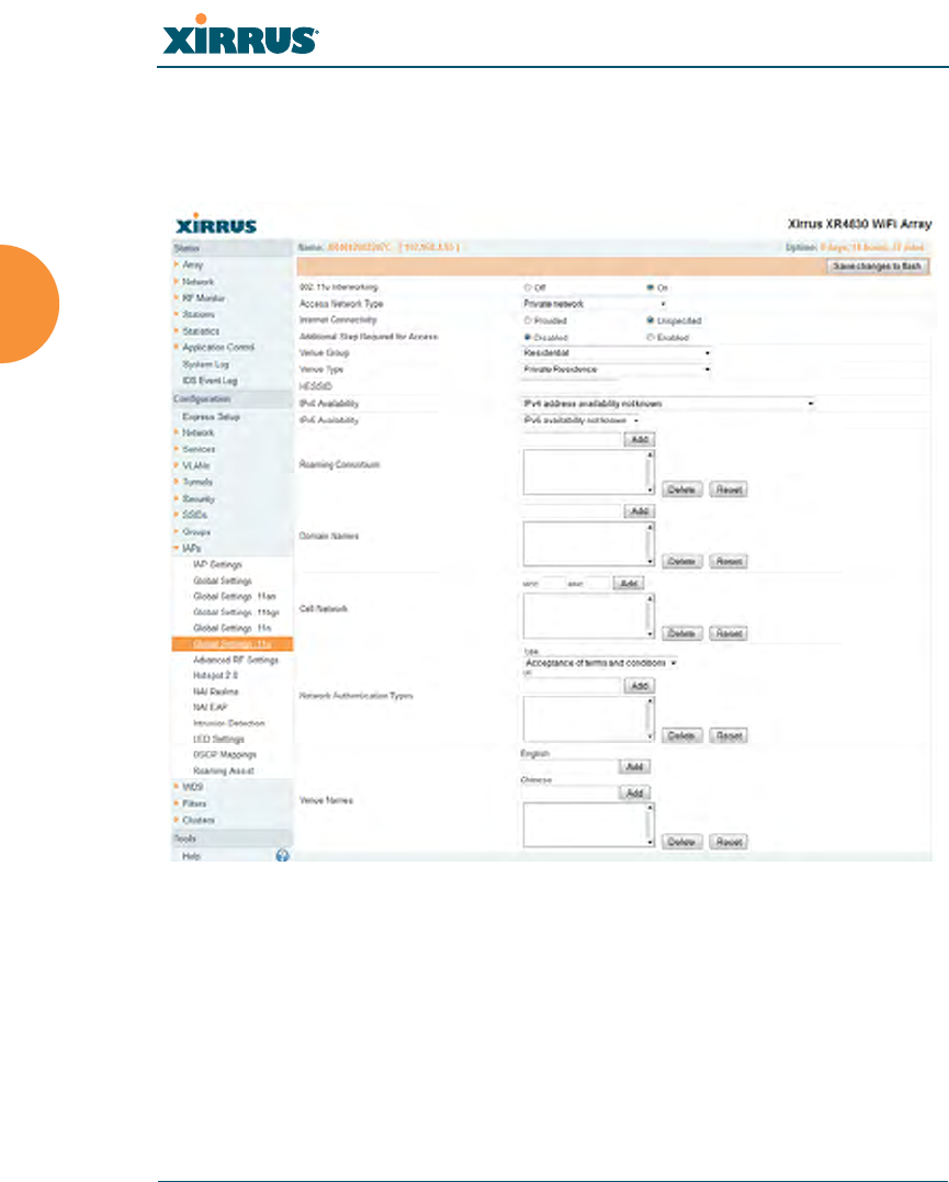
Wireless Array
308 Configuring the Wireless Array
Cellular Networks. The service network may have arrangements with
one or more cellular service providers who can transparently provide
wireless and Internet connectivity.
Figure 152. 802.11u Global Settings
Procedure for Configuring 802.11u Settings
Use this window to establish the 802.11u configuration.
1. 802.11u Internetworking. Click On to enable 802.11u protocol operation.
2. Access Network Type: This indicates the type of network supported by
the access point. The choices are:

Wireless Array
Configuring the Wireless Array 309
a. Chargeable public network
b. Emergency services only network
c. Free public network
d. Personal device network
e. Private network with guest access
f. Test or experimental network
g. Wildcard
3. Internet Connectivity. Click Provided if Internet connectivity is available
through the access point from the back end provider to which the mobile
user ends up belonging. Click Unspecified otherwise—for example,
depending on the SLAs (service level agreements) of the mobile user,
Internet access may or may not be provided.
4. Additional Step Required for Access. Click Disabled if no additional
authentication steps will be required to complete the connection and
Enabled otherwise. The available authentication techniques are described
in the Network Authentication Types field (Step 13).
5. Venue Group. Select the general type of venue that the access point is
located in. Various choices are available, including Business, Residential,
and Outdoor. For each Ven ue Gr oup , a further set of sub-choices are
available in the Venu e Type field below. The particular name of the venue
is specified in the Ven ue Nam es field (Step 14).
6. Venue Type. For each of the Venue Group choices, a further set of sub-
choices are available. For example, if you set Venue Group to Assembly,
the choices include Amphitheater, Area, Library, and Theatre.
7. HESSID. Enter the globally unique homogeneous ESS ID. This SSID is
marked as being HotSpot 2.0 capable. This SSID attribute is global—if
802.11u is enabled and HotSpot 2.0 is enabled, then all SSIDs will have
HotSpot 2.0 capability.

Wireless Array
310 Configuring the Wireless Array
8. IPv4 Availability. Select the type of IPv4 addressing that will be assigned
by the network upon connection. NATed addresses are IP addresses that
have been changed by mapping the IP address and port number to IP
addresses and new port numbers routable by other networks. Double
NATed addresses go through two levels of NATing. Port restricted IPv4
addresses refer to specific UDP and TCP port numbers associated with
standard Internet services; for example, port 80 for web pages. The
choices for this field are:
a. Double NATed private IPv4 address available
b. IPv4 address not available
c. IPv4 address availability not known
d. Port-restricted IPv4 address available
e. Port-restricted IPv4 address and double NATed IPv4 address
available
f. Port-restricted IPv4 address and single NATed IPv4 address
available
g. Public IPv4 address available
h. Single NATed private IPv4 address available
9. IPv6 Availability. Select the type of IPv6 addressing that is available from
the network upon connection.
a. IPv6 address not available
b. IPv6 address availability not known
c. IPv6 address available
10. Roaming Consortium. Each of the roaming consortia has an
organizational identifier (OI) obtained from IEEE that unique identifies
the organization. This is similar to the OUI part of a MAC address. Use
this control to build up a list of OIs for the consortia available. Enter the
OI as a hexadecimal string of between 6 and 30 characters in the Add field

Wireless Array
Configuring the Wireless Array 311
and click Add. The OI will appear in the list. An OI may be deleted by
selecting it in the list and clicking Delete. All OIs may be deleted by
clicking Reset.
11. Domain Names. Use this control to build up a list of domain names.
Enter the name in the Add field and click Add, and it will appear in the
list. A name may be deleted by selecting it in the list and clicking Delete.
All names may be deleted by clicking Reset.
12. Cell Network. Each of the cell networks is identified by a mobile country
code (MCC) and mobile network code (MNC). Use this control to build
up a list of cell networks. Enter the MCC as a three digit number and the
MNC as a two or three digit number and click Add. The cell network will
appear in the list. A cell network may be deleted by selecting it in the list
and clicking Delete. All networks may be deleted by clicking Reset.
13. Network Authentication Types. Each network authentication that is in
use on the network should be specified in this list. The choices are:
a. Acceptance of terms and conditions. This choice displays a web page
asking for the user’s acceptance of terms and conditions of use. The
URL should be specified in the URL field before clicking Add.
b. DNS redirection.
c. HTTP/HTTPS redirection. This choice causes the user’s first web
page reference to be redirected to a different URL for login or other
information. The URL should be specified in the URL field before
clicking Add.
d. On-line enrollment supported. This choice indicates that the user
may sign up for network access as part of the authentication process.
When Add is clicked the authentication type and optional URL will
appear in the list. An authentication type may be deleted by selecting it in
the list and clicking Delete. All authentication types may be deleted by
clicking Reset.

Wireless Array
312 Configuring the Wireless Array
14. Venue Names. The list of names associated with the venue are specified
here. A venue name may be added to the list in English or Chinese. Enter
the name in the appropriate field and click Add. The name will appear in
the list. A name may be deleted by selecting it in the list and clicking
Delete. All names may be deleted by clicking Reset.
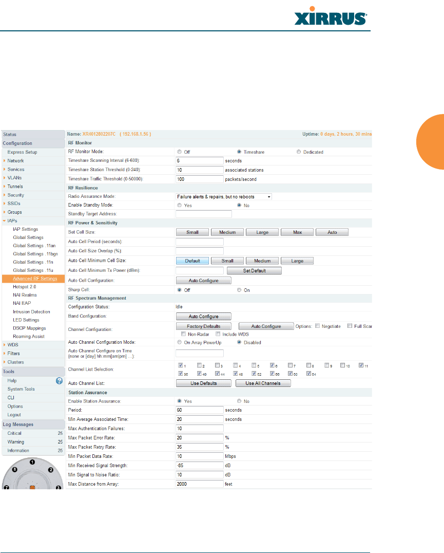
Wireless Array
Configuring the Wireless Array 313
Advanced RF Settings
This window allows you to establish RF settings, including automatically
configuring channel allocation and cell size, and configuring radio assurance and
standby modes. Changes you make on this page are applied to all IAPs, without
exception.
Figure 153. Advanced RF Settings

Wireless Array
314 Configuring the Wireless Array
About Standby Mode
Standby Mode supports the Array-to-Array fail-over capability. When you enable
Standby Mode, the Array functions as a backup unit, and it enables its radios if it
detects that its designated target Array has failed. The use of redundant Arrays to
provide this fail-over capability allows Arrays to be used in mission-critical
applications. In Standby Mode, an Array monitors beacons from the target Array.
When the target has not been heard from for 40 seconds, the standby Array
enables its radios until it detects that the target Array has come back online.
Standby Mode is off by default. Note that you must ensure that the configuration
of the standby Array is correct. This window allows you to enable or disable
Standby Mode and specify the primary Array that is the target of the backup unit.
See also, “Failover Planning” on page 42.
Procedure for Configuring Advanced RF Settings
RF Monitor
1. RF Monitor Mode: RF monitoring permits the operation of features like
intrusion detection. The monitor may operate in Dedicated mode, or in
Timeshare mode which allows the radio to divide its time between
monitoring and acting as a standard radio that allows stations to associate
to it. Timeshare mode is especially useful for small Arrays with two IAPs,
such as the XR500 and XR-1000 Series, allowing one IAP to be shared
between monitoring the airwaves for problems and providing services to
stations. Settings allow you to give priority to monitoring or wireless
services, depending on your needs.
Some of the features below, such as Auto Configure for Cell Size and
Channel Configuration, are only available if the Array’s license includes the
Xirrus Advanced RF Performance Manager (RPM). If a setting is
unavailable (grayed out), then your license does not support the feature.
Please see “About Licensing and Upgrades” on page 361.
Other features below, such as RF Intrusion Detection, are only available if
the Array’s license includes the Xirrus Advanced RF Security Manager
(RSM).

Wireless Array
Configuring the Wireless Array 315
If Timeshare mode is selected, you may adjust the following settings:
•Timeshare Scanning Interval (6-600): number of seconds between
monitor (off-channel) scans.
•Timeshare Station Threshold (0-240): when the number of stations
associated to the monitor radio exceeds this threshold, scanning is
halted.
•Timeshare Traffic Threshold (0-50000): when the number of packets
per second handled by the monitor radio exceeds this threshold,
scanning is halted.
RF Resilience
2. Radio Assurance Mode: When this mode is enabled, the monitor radio
performs loopback tests on the Array. This mode requires RF Monitor
Mode to be enabled (Step 1) to enable self-monitoring functions. It also
requires a radio to be set to monitoring mode (see “Enabling Monitoring
on the Array” on page 460).
Operation of Radio Assurance mode is described in detail in “Array
Monitor and Radio Assurance Capabilities” on page 460.
The Radio Assurance mode scans and sends out probe requests on each
channel, in turn. It listens for all probe responses and beacons. These tests
are performed continuously (24/7). If no beacons or probe responses are
observed from a radio for a predetermined period, Radio Assurance
mode will take action according to the preference that you have specified:
•Failure alerts only — The Array will issue alerts in the Syslog, but
will not initiate repairs or reboots.
•Failure alerts & repairs, but no reboots — The Array will issue alerts
and perform resets of one or all of the radios if needed.
•Failure alerts & repairs & reboots if needed — The Array will issue
alerts, perform resets, and schedule reboots if needed.
•Disabled — Disable IAP radio assurance tests (no self-monitoring
occurs). Loopback tests are disabled by default.

Wireless Array
316 Configuring the Wireless Array
3. Enable Standby Mode: Choose Yes to enable this Array to function as a
backup unit for the target Array, or choose No to disable this feature. See
“About Standby Mode” on page 314.
4. Standby Target Address: If you enabled the Standby Mode, enter the
MAC address of the target Array (i.e., the address of the primary Array
that is being monitored and backed up by this Array). To find this MAC
address, open the Array Info window on the target Array, and use the
Gigabit1 MAC Address.
RF Power & Sensitivity
For an overview of RF power and cell size settings, please see “Capacity and Cell
Sizes” on page 30 and “Fine Tuning Cell Sizes” on page 31.
5. Set Cell Size: Cell Size may be set globally for all enabled IAPs to Auto,
Large, Medium, Small, or Max using the buttons.
6. Auto Cell Period (seconds): You may set up auto-configuration to run
periodically, readjusting optimal cell sizes for the current conditions.
Enter a number of seconds to specify how often auto-configuration will
run. If you select None, then auto-configuration of cell sizing will not be
run periodically. You do not need to run Auto Cell often unless there are a
lot of changes in the environment. If the RF environment is changing
often, running Auto Cell every twenty-four hours (86400 seconds) should
be sufficient). The default value is None.
To use the Auto Cell Size feature, the following additional settings are
required:
RF Monitor Mode must be turned On. See “RF Monitor” on page 314.
One of the radios must be in monitor mode, and all other IAPs that will use
Auto Cell must have Cell Size set to auto. See “Procedure for Manually
Configuring IAPs” on page 275.

Wireless Array
Configuring the Wireless Array 317
7. Auto Cell Size Overlap (%): Enter the percentage of cell overlap that will
be allowed when the Array is determining automatic cell sizes. For 100%
overlap, the power is adjusted such that neighboring Arrays that hear
each other best will hear each other at -70dB. For 0% overlap, that number
is -90dB. The default value is 50%.
8. Auto Cell Min Cell Size: Use this setting if you wish to set the minimum
cell size that Auto Cell may assign. The values are Default, Large,
Medium, or Small.
9. Auto Cell Min Tx Power (dBm): Enter the minimum transmit power that
the Array can assign to a radio when adjusting automatic cell sizes. The
default value is 10.
10. Auto Cell Configuration: Click this button to instruct the Array to
determine and set the best cell size for each enabled IAP whose Cell Size
is auto on the IAP Settings window, based on changes in the
environment. This is the recommended method for setting cell size. You
may look at the Tx and Rx values on the IAP Settings window to view the
cell size settings that were applied.
11. Sharp Cell: This feature reduces interference between neighboring
Arrays or other Access Points by limiting to a defined boundary (cell size)
the trailing edge bleed of RF energy. Choose On to enable the Sharp Cell
functionality, or choose Off to disable this feature. See also, “Fine Tuning
Cell Sizes” on page 31.
The Sharp Cell feature only works when the cell size is Small, Medium, or
Large (or Auto) — but not Max. If an IAP cell size is set to Max, the Sharp
Cell feature will be disabled for that radio.

Wireless Array
318 Configuring the Wireless Array
RF Spectrum Management
12. Configuration Status: Shows the status of auto channel configuration. If
an operation is in progress, the approximate time remaining until
completion is displayed; otherwise Idle is displayed.
13. Band Configuration: Automatic band configuration is the recommended
method for assigning bands to the abgn IAPs. It runs only on command,
assigning IAPs to the 2.4GHz or 5GHz band when you click the Auto
Configure button. The Array uses its radios to listen for other APs on the
same channel, and it assigns bands based on where it finds the least
interference.
Auto band assigns as many IAPs to the 5 GHz band as possible when
there are other Arrays within earshot. It does this by determining how
many Arrays are in range and then picking the number of radios to place
in the 2.4 GHz band. Note that for another Array to be considered to be in
range, the other Array must be visible via both the wireless and wired
networks—the Array must be listed in the Network Map table, its entry
must have In Range set to Yes, and it must have at least one active IAP
with an SSID that has broadcast enabled.
Auto band runs separately from auto channel configuration. If the band is
changed for an IAP, associated stations will be disconnected and will then
reconnect.
14. Channel Configuration: Automatic channel configuration is the
recommended method for channel allocation. When the Array performs
auto channel configuration, you may optionally instruct it to first
negotiate with any other nearby Arrays that have been detected, to
determine whether to stagger the start time for the procedure slightly.
Thus, nearby Arrays will not run auto channel at the same time. This
prevents Arrays from interfering with each other’s channel assignments.
The Configuration Status field displays whether an Auto Configure
cycle is currently running on this Array or not.
Click Auto Configure to instruct the Array to determine the best channel
allocation settings for each enabled IAP and select the channel

Wireless Array
Configuring the Wireless Array 319
automatically, based on changes in the environment. This is the
recommended method for channel allocation (see “RF Spectrum
Management” on page 318). The following options may be selected for
auto configuration:
•Negotiate: negotiate air-time with other Arrays before performing a
full scan. Negotiating is slower, but if multiple Arrays are configuring
channels at the same time the Negotiate option ensures that multiple
Arrays don't select the same channels. Turning off the Negotiate
option allows the Auto Configure button to manually perform auto
channel without waiting, and may be used when you know that no
other nearby Arrays are configuring their channels.
•Full Scan: perform a full traffic scan on all channels on all IAPs to
determine the best channel allocation.
•Non-Radar: give preference to channels without radar-detect. See
table in “Procedure for Configuring Global 802.11an IAP Settings” on
page 293.
•Include WDS: automatically assign 5GHz to WDS client links.
Click Factory Defaults if you wish to instruct the Array to return all IAPs
to their factory preset channels. As of release 6.3, Arrays no longer all use
the same factory preset values for channel assignments. Instead, if the
Array has been deployed for a while and already has data from the
spectrum analyzer and Xirrus Roaming Protocol about channel usage on
neighboring arrays, it performs a quick auto channel using that
information (without doing a full RF scan) to make an intelligent choice
of channel assignments. If the Array has been rebooted and has no saved
configuration or is just being deployed for the first time, it has no prior
data about its RF environment. In this case, it will pick a set of compatible
channel assignments at random.
On the XR-1000 Series Arrays, the Factory Defaults button will not
restore iap1 to monitor mode. You will need to restore this setting manually.
Also, you may need to set RF Monitor Mode to Timeshare Mode again -
see “RF Monitor” on page 314.

Wireless Array
320 Configuring the Wireless Array
15. Auto Channel Configuration Mode: This option allows you to instruct
the Array to auto-configure channel selection for each enabled IAP when
the Array is powered up. Choose On Array PowerUp to enable this
feature, or choose Disabled to disable this feature.
16. Auto Channel Configure on Time: This option allows you to instruct the
Array to auto-configure channel selection for each enabled IAP at a time
you specify here. Leave this field blank unless you want to specify a time
at which the auto-configuration utility is initiated. Time is specified in
hours and minutes, using the format: [day]hh:mm [am|pm]. If you omit
the optional day specification, channel configuration will run daily at the
specified time. If you do not specify am or pm, time is interpreted in 24-
hour military time. For example, Sat 11:00 pm and Saturday 23:00 are
both acceptable and specify the same time.
17. Channel List Selection: This list selects which channels are available to
the auto channel algorithm. Channels that are not checked are left out of
the auto channel selection process. Note that channels that have been
locked by the user are also not available to the auto channel algorithm.
18. Auto Channel List: Use All Channels selects all available channels (this
does not include locked channels). Use Defaults sets the auto channel list
back to the defaults. This omits newer channels (100-140) — many
wireless NICs don’t support these channels.
Station Assurance
Station assurance monitors the quality of the connections that users are
experiencing on the wireless network. You can quickly detect stations that are
having problems and take steps to correct them. Use these settings to establish
threshold values for errors and other problems. Station assurance is enabled by
default, with a set of useful default thresholds that you may adjust as desired.
When a connection is experiencing problems and reaches one of these thresholds
in the specified period of time, the Array responds with several actions: an event
is triggered, a trap is generated, and a Syslog message is logged. For example, if a
client falls below the threshold for Min Average Associated Time, this
“bouncing” behavior might indicate roaming problems with the network’s RF
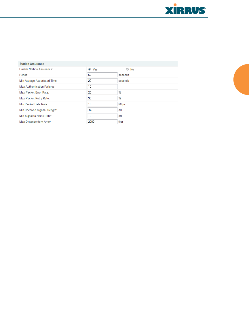
Wireless Array
Configuring the Wireless Array 321
design, causing the client to bounce between multiple arrays and not stay
connected longer than the time to re-associate and then jump again. This can be
corrected with RF adjustments. Station assurance alerts you to the fact that this
station is encountering problems.
Figure 154. Station Assurance (Advanced RF Settings)
19. Enable Station Assurance: This is enabled by default. Click No if you
wish to disable it, and click Yes to re-enable it. When station assurance is
enabled, the Array will monitor connection quality indicators listed
below and will display associated information on the Station Assurance
Status page. When a threshold is reached, an event is triggered, a trap is
generated, and a Syslog message is logged.
20. Period: In seconds, the period of time for a threshold to be reached. For
example, the Array will check whether Max Authentication Failures has
been reached in this number of seconds.
21. Min Average Associated Time: (seconds) Station assurance detects
whether the average length of station associations falls below this
threshold during a period.
22. Max Authentication Failures: Station assurance detects whether the
number of failed login attempts reaches this threshold during a period.
23. Max Packet Error Rate: (%) Station assurance detects whether the packet
error rate percentage reaches this threshold during a period.

Wireless Array
322 Configuring the Wireless Array
24. Max Packet Retry Rate: (%) Station assurance detects whether the packet
retry rate percentage reaches this threshold during a period.
25. Min Packet Data Rate: (Mbps) Station assurance detects whether the
packet data rate falls below this threshold during a period.
26. Min Received Signal Strength: (dB) Station assurance detects whether
the strength of the signal received from the station falls below this
threshold during a period.
27. Min Signal to Noise Ratio: (dB) Station assurance detects whether the
ratio of signal to noise received from the station falls below this threshold
during a period.
28. Max Distance from Array: Min Received Signal Strength: (feet) Station
assurance detects whether the distance of the station from the Array
reaches this threshold during a period.
See Also
Coverage and Capacity Planning
Global Settings .11an
Global Settings .11bgn
Global Settings .11n
IAPs
IAP Settings
Radio Assurance
Hotspot 2.0
Understanding Hotspot 2.0
Hotspot 2.0 is a part of the Wi-Fi Alliance’s Passpoint certification program. It
specifies additional information above and beyond that found in 802.11u, which
allows mobile clients to automatically discover, select, and connect to networks
based on preferences and network optimization. Mobile clients that support
Hotspot 2.0 are informed of an access point’s support via its beacon message.
Hotspot 2.0 messages forward several types of information to clients, including:

Wireless Array
Configuring the Wireless Array 323
Uplink and Downlink Speeds
Link Status
Friendly Name
Connection Capabilities The access point will restrict the protocols that
can be used by a specification of protocol and port numbers.
Procedure for Hotspot 2.0 Settings
Use this window to establish the Hotspot 2.0 configuration.
1. Hotspot 2.0. Click Enabled to enable Hotspot 2.0 operation.
2. Downstream Group-addressed Forwarding. Click Enabled to allow the
access point to forward group-addressed traffic (broadcast and multicast)
to all connected devices. Click Disabled to cause the access point to
convert group-addressed traffic to unicast messages.
3. WAN Downlink Speed. Enter the WAN downlink speed in kbps into the
field.
4. WAN Uplink Speed. Enter the WAN uplink speed in kbps into the field.
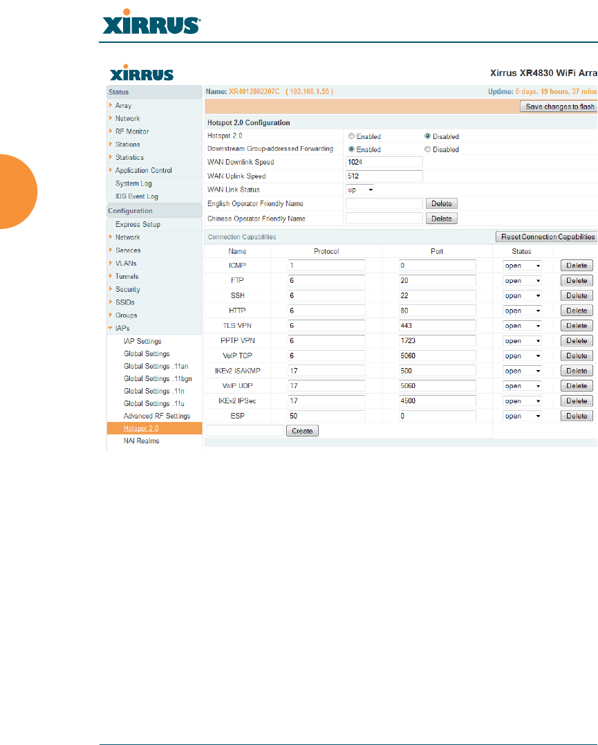
Wireless Array
324 Configuring the Wireless Array
Figure 155. Hotspot 2.0 Settings
5. English/Chinese Operator Friendly Name. Enter an English or Chinese
name into one of the fields. An incorrectly entered name can be deleted
by clicking the corresponding Delete.
6. Connection Capabilities. A Hotspot 2.0 access point limits the particular
protocols that clients may use. The set of default protocols is shown
initially. This table specifies the protocols in terms of:
a. A common Name, such as FTP or HTTP.
b. A Protocol number. For example 1 for ICMP, 6 for TCP, 17 for UDP,
and 50 for Encapsulated Security Protocol in IPsec VPN connections.
c. Port number for UDP/TCP connection.
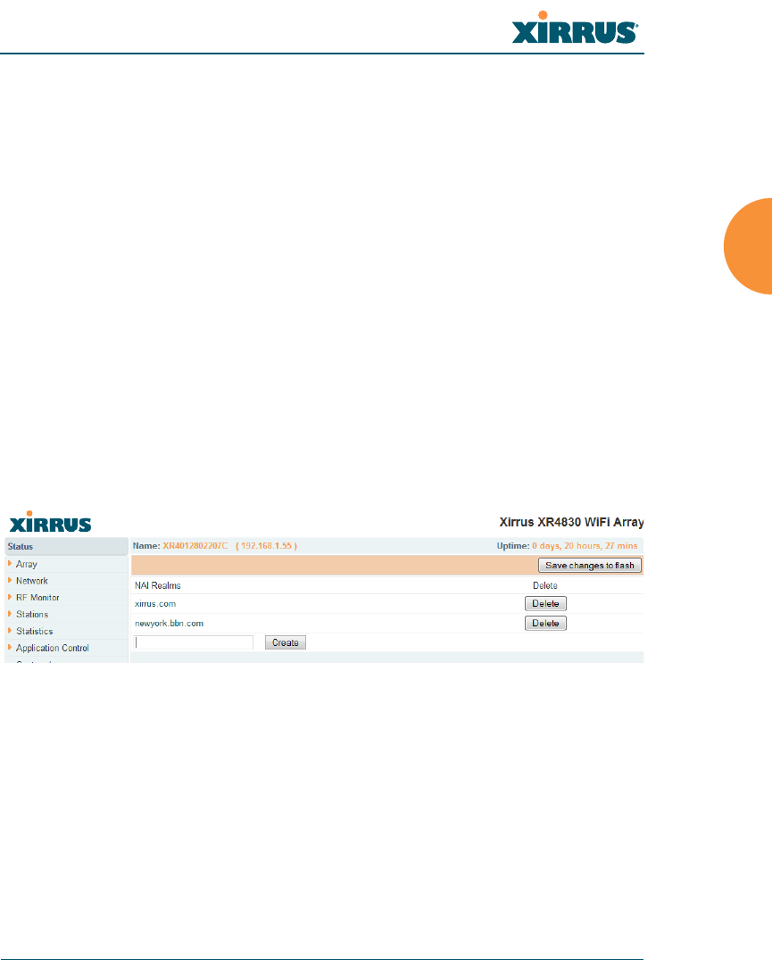
Wireless Array
Configuring the Wireless Array 325
d. Status: one of open, closed or unknown.
Any of the entries may be deleted by clicking the corresponding Delete
button. New entries may be created by entering the name of the protocol
in the box beside the Create button, and then clicking Create. The new
protocol will be added to the list with zeros in the protocol fields and
unknown for the status. Enter the appropriate Protocol and Port values
before setting the Status field to open.
NAI Realms
Understanding NAI Realm Authentication
A network access identifier (NAI) is a specification of a particular user. A NAI
takes the general form of e-mail addresses. Examples of NAIs are:
joe@example.com
fred@foo-9.example.com
jack@3rd.depts.example.com
fred.smith@example.com
Figure 156. NAI Realms
The NAI Realm is the part of the NAI following the @ sign. In the examples
above, the realms are: example.com, 3rd.depts.example.com, and
foo-9.example.com. Use the NAI Realms page, in conjunction with the NAI EAP
page, to specify the authentication techniques to be used to access that realm with
appropriate parameters.
Procedure for NAI Realms Settings
Use this window to establish the names of the supported realms.
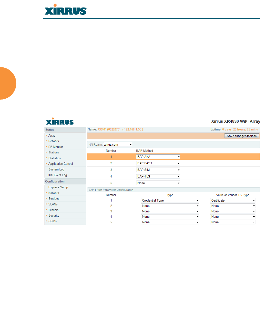
Wireless Array
326 Configuring the Wireless Array
1. Enter the realm name. Enter the name of a realm in the box to the left of
the Create button and click Create. The realm will be added to the NAI
Realms list. Any of the realms may be deleted by clicking the
corresponding Delete button.
2. Enter Authentication Information. The NAI EAP page is used to specify
authentication for a realm. Click on the name of a realm to go to the NAI
EAP page for that realm. See “NAI EAP” on page 326.
NAI EAP
This window allows specification of the authentication techniques for a realm.
Figure 157. NAI EAP
Procedure for NAI Realms Settings
1. Select the realm to be configured in the NAI Realm drop down.
2. Select EAP Methods. Each realm may support up to five EAP
authentication methods. Beside each of the five numbers (1, 2, 3, 4, 5)
select the method from the drop down. The choices are:
•EAP-AKA
•EAP-AKA’ (EAP-AKA prime)

Wireless Array
Configuring the Wireless Array 327
•EAP-FAST
•EAP-MSCHAP-V2
•EAP-SIM
•EAP-TLS
•EAP-TTLS
•GTC
•MD5-Challenge
•None
•PEAP
3. Specify Authentication Parameters. Each of the authentication methods
may specify up to five authentication parameters. To specify the
parameters click on the number corresponding to the authentication
method; i.e. 1, 2, 3, 4, or 5. This displays the EAP n Auth Parameter
Configuration below the list of EAP Methods. For up to five of the
parameters, select the Type and Value or Vendor ID / Type. The choices
for the Type are:
•Credential Type
•Expanded EAP Method
•Expanded Inner EAP Method
•Inner Authentication EAP Method Type
•Non-EAP Inner Authentication Type
•None
•Tunneled EAP Method Credential Type
For each type, a value or a vendor ID and type must be specified, as
applicable.
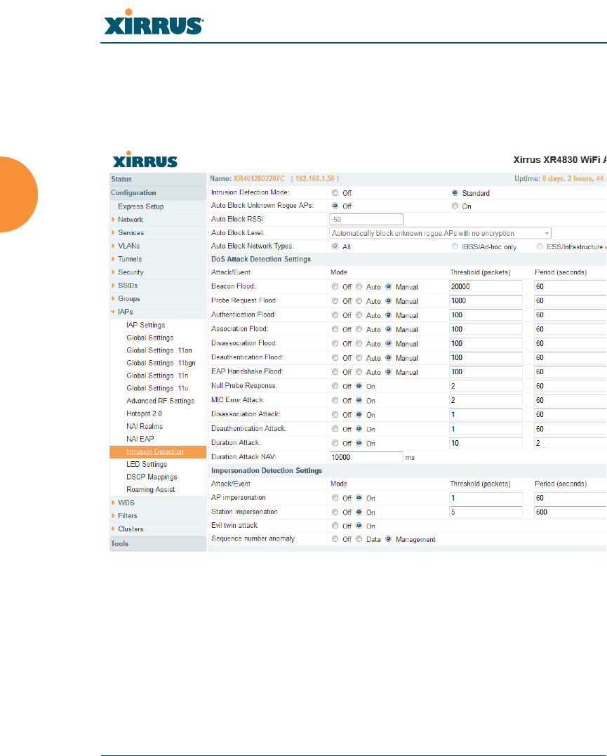
Wireless Array
328 Configuring the Wireless Array
Intrusion Detection
The Xirrus Array employs a number of IDS/IPS (Intrusion Detection System/
Intrusion Prevention System) strategies to detect and prevent malicious attacks on
the wireless network. Use this window to adjust intrusion detection settings.
Figure 158. Intrusion Detection Settings
The Array provides a suite of intrusion detection and prevention options to
improve network security. You can separately enable detection of the following
types of problems:
Rogue Access Point Detection and Blocking
Unknown APs are detected, and may be automatically blocked based on
a number of criteria. See “About Blocking Rogue APs” on page 331.

Wireless Array
Configuring the Wireless Array 329
Denial of Service (DoS) or Availability Attack Detection
A DoS attack attempts to flood an Array with communications requests
so that it cannot respond to legitimate traffic, or responds so slowly that it
becomes effectively unavailable. The Array can detect a number of types
of DoS attacks, as described in the table below.
Impersonation Detection
These malicious attacks use various techniques to impersonate a
legitimate AP or station, often in order to eavesdrop on wireless
communications. The Array detects a number of types of impersonation
attacks, as described in the table below.
Type of Attack Description
DoS Attacks
Beacon Flood Generating thousands of counterfeit 802.11 beacons to
make it hard for stations to find a legitimate AP.
Probe Request
Flood Generating thousands of counterfeit 802.11 probe requests
to overburden the Array.
Authentication
Flood Sending forged Authenticates from random MAC
addresses to fill the Array's association table.
Association
Flood Sending forged Associates from random MAC addresses
to fill the Array's association table.
Disassociation
Flood Flooding the Array with forged Disassociation packets.
Deauthentication
Flood Flooding the Array with forged Deauthenticates.
EAP Handshake
Flood Flooding an AP with EAP-Start messages to consume
resources or crash the target.
Null Probe
Response Answering a station probe-request frame with a null SSID.
Many types of popular NIC cards cannot handle this
situation, and will freeze up.

Wireless Array
330 Configuring the Wireless Array
MIC Error Attack Generating invalid TKIP data to exceed the Array's MIC
error threshold, suspending WLAN service.
Disassociation
Attack (Omerta) Sending forged disassociation frames to all stations on a
channel in response to data frames.
Deauthentication
Attack Sending forged deauthentication frames to all stations on
a channel in response to data frames.
Duration Attack
(Duration Field
Spoofing)
Injecting packets into the WLAN with huge duration
values. This forces the other nodes in the WLAN to keep
quiet, since they cannot send any packet until this value
counts down to zero. If the attacker sends such frames
continuously it silences other nodes in the WLAN for long
periods, thereby disrupting the entire wireless service.
Impersonation Attacks
AP
impersonation Reconfiguring an attacker's MAC address to pose as an
authorized AP. Administrators should take immediate
steps to prevent the attacker from entering the WLAN.
Station
impersonation Reconfiguring an attacker's MAC address to pose as an
authorized station. Administrators should take immediate
steps to prevent the attacker from entering the WLAN.
Evil twin attack Masquerading as an authorized AP by beaconing the
WLAN's service set identifier (SSID) to lure users.
Sequence
number anomaly A sender may use an Add Block Address request (ADDBA
- part of the Block ACK mechanism) to specify a sequence
number range for packets that the receiver can accept.
An attacker spoofs an ADDBA request, asking the receiver
to reset its sequence number window to a new range. This
causes the receiver to drop legitimate frames, since their
sequence numbers will not fall in that range.
Type of Attack Description

Wireless Array
Configuring the Wireless Array 331
About Blocking Rogue APs
If you classify a rogue AP as blocked (see “Rogue Control List” on page 240), then
the Array will take measures to prevent stations from staying associated to the
rogue. When the monitor radio is scanning, any time it hears a beacon from a
blocked rogue it sends out a broadcast “deauth” signal using the rogue's BSSID
and source address. This has the effect of disconnecting all of a rogue AP’s clients
approximately every 5 to 10 seconds, which is enough to make the rogue
frustratingly unusable.
The Advanced RF Settings window allows you to set up Auto Block parameters
so that unknown APs get the same treatment as explicitly blocked APs. This is
basically a “shoot first and ask questions later” mode. By default, auto blocking is
turned off. Auto blocking provides two parameters for qualifying blocking so that
APs must meet certain criteria before being blocked. This keeps the Array from
blocking every AP that it detects. You may:
Set a minimum RSSI value for the AP — for example, if an AP has an RSSI
value of -90, it is probably a harmless AP belonging to a neighbor and not
in your building.
Block based on encryption level.
Block based on whether the AP is part of an ad hoc network or
infrastructure network.
Procedure for Configuring Intrusion Detection
RF Intrusion Detection and Auto Block Mode
1. Intrusion Detection Mode: This option allows you to choose the
Standard intrusion detection method, or you can choose Off to disable
this feature. See “Array Monitor and Radio Assurance Capabilities” on
page 460 for more information.
•Standard — enables the monitor radio to collect Rogue AP
information.
•Off — intrusion detection is disabled.

Wireless Array
332 Configuring the Wireless Array
2. Auto Block Unknown Rogue APs: Enable or disable auto blocking (see
“About Blocking Rogue APs” on page 331). Note that in order to set Auto
Block RSSI and Auto Block Level, you must set Auto Block Unknown
Rogue APs to On. Then the remaining Auto Block fields will be active.
3. Auto Block RSSI: Set the minimum RSSI for rogue APs to be blocked.
APs with lower RSSI values will not be blocked. They are assumed to be
farther away, and probably belonging to neighbors and posing a minimal
threat.
4. Auto Block Level: Select rogue APs to block based on the level of
encryption that they are using. The choices are:
•Automatically block unknown rogue APs regardless of encryption.
•Automatically block unknown rogue APs with no encryption.
•Automatically block unknown rogue APs with WEP or no
encryption.
5. Auto Block Network Types: Select rogues to automatically block by
applying the criteria above only to networks of the type specified below.
The choices are:
•All — the unknown rogues may be part of any wireless network.
•IBSS/AD Hoc only — only consider auto blocking rogues if they
belong to an ad hoc wireless network (a network of client devices
without a controlling Access Point, also called an Independent Basic
Service Set — IBSS).
•ESS/Infrastructure only — only consider auto blocking rogue APs if
they are in infrastructure mode rather than ad hoc mode.
DoS Attack Detection Settings
6. Attack/Event: The types of DoS attack that you may detect are described
in the Type of Attack Table on page 329. Detection of each attack type
may be separately enabled or disabled. For each attack, a default
Threshold and Period (seconds) are specified. If the number of
occurrences of the type of packet being detected exceeds the threshold in

Wireless Array
Configuring the Wireless Array 333
the specified number of seconds, then the Array declares that an attack
has been detected. You may modify the Threshold and Period.
For the Flood attack settings, you also have a choice of Auto or Manual.
•Manual mode — threshold and period settings are used to detect a
flood. Packets received are simply counted for the specified time
period and compared against the flood threshold. The default for all
of the floods is Manual mode.
•Auto mode — the Array analyzes current traffic for packets of a given
type versus traffic over the past hour to determine whether a packet
flood should be detected. In this mode, threshold and period settings
are ignored. This mode is useful for floods like beacon or probe
floods, where the numbers of such packets detected in the air can
vary greatly from installation to installation.
7. Duration Attack NAV (ms): For the duration attack, you may also modify
the default duration value that is used to determine whether a packet
may be part of an attack. If the number of packets having at least this
duration value exceeds the Threshold number in the specified Period, an
attack is detected.
Impersonation Detection Settings
8. Attack/Event: The types of impersonation attack that you may detect are
described in Impersonation Attacks on page 330. Detection of each attack
type may be turned On or Off separately. For AP or Station
Impersonation attacks, a default Threshold and Period (seconds) are
specified. If the number of occurrences of the type of packet being
detected exceeds the threshold in the specified number of seconds, then
the Array declares that an attack has been detected. You may modify the
Threshold and Period.
9. Sequence number anomaly: You may specify whether to detect this type
of attack in Data traffic or in Management traffic, or turn Off this type of
detection.
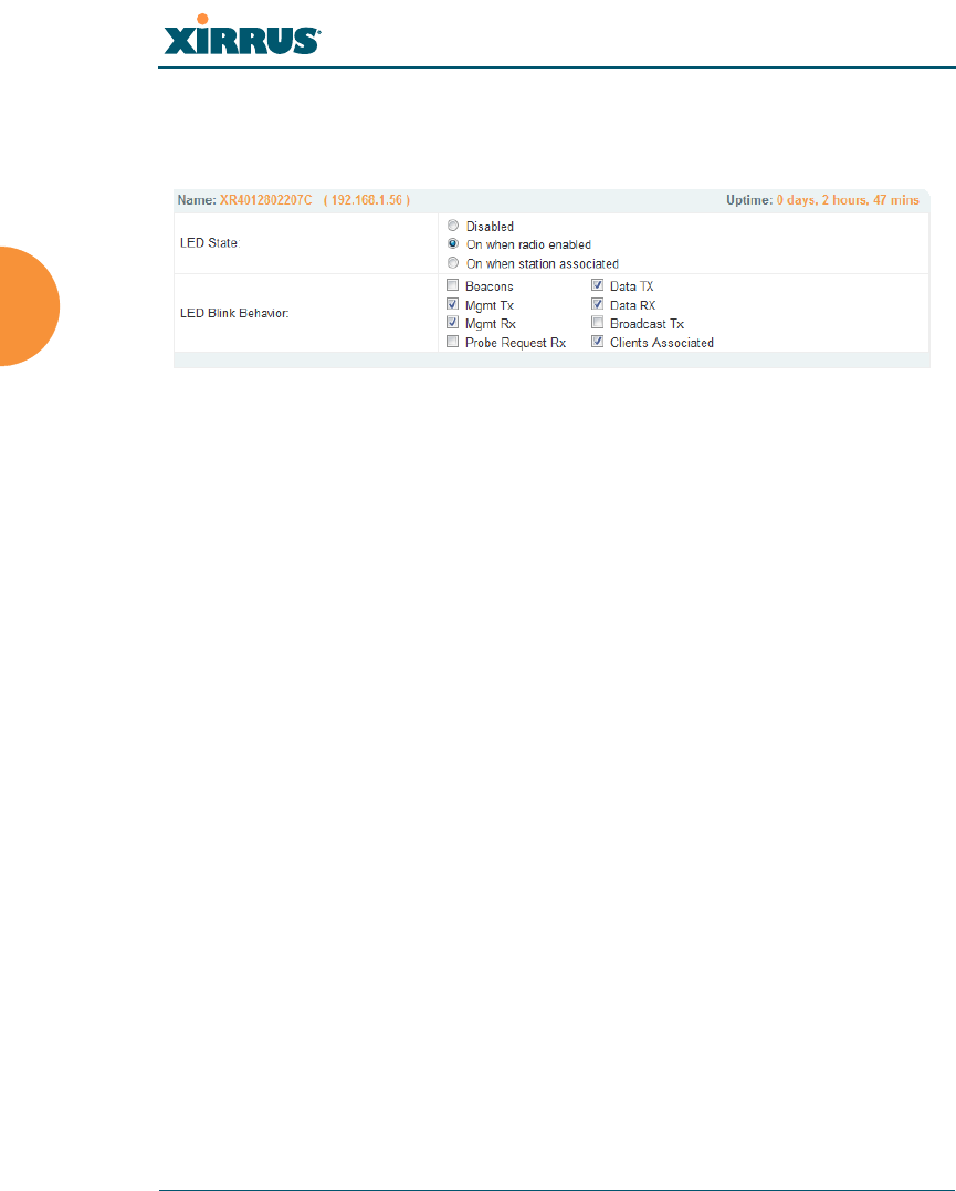
Wireless Array
334 Configuring the Wireless Array
LED Settings
This window assigns behavior preferences for the Array’s IAP LEDs.
Figure 159. LED Settings
Procedure for Configuring the IAP LEDs
1. LED State: This option determines which event triggers the LEDs, either
when an IAP is enabled or when an IAP first associates with the network.
Choose On Radio Enabled or On First Association, as desired. You may
also choose Disabled to keep the LEDs from being lit. The LEDs will still
light during the boot sequence, then turn off.
2. LED Blink Behavior: This option allows you to select when the IAP LEDs
blink, based on the activities you check here. From the choices available,
select one or more activities to trigger when the LEDs blink. For default
behavior, see “Array LED Operating Sequences” on page 64.
3. Click Save changes to flash if you wish to make your changes
permanent.
See Also
Global Settings (IAP)
Global Settings .11an
Global Settings .11bgn
IAPs
LED Boot Sequence
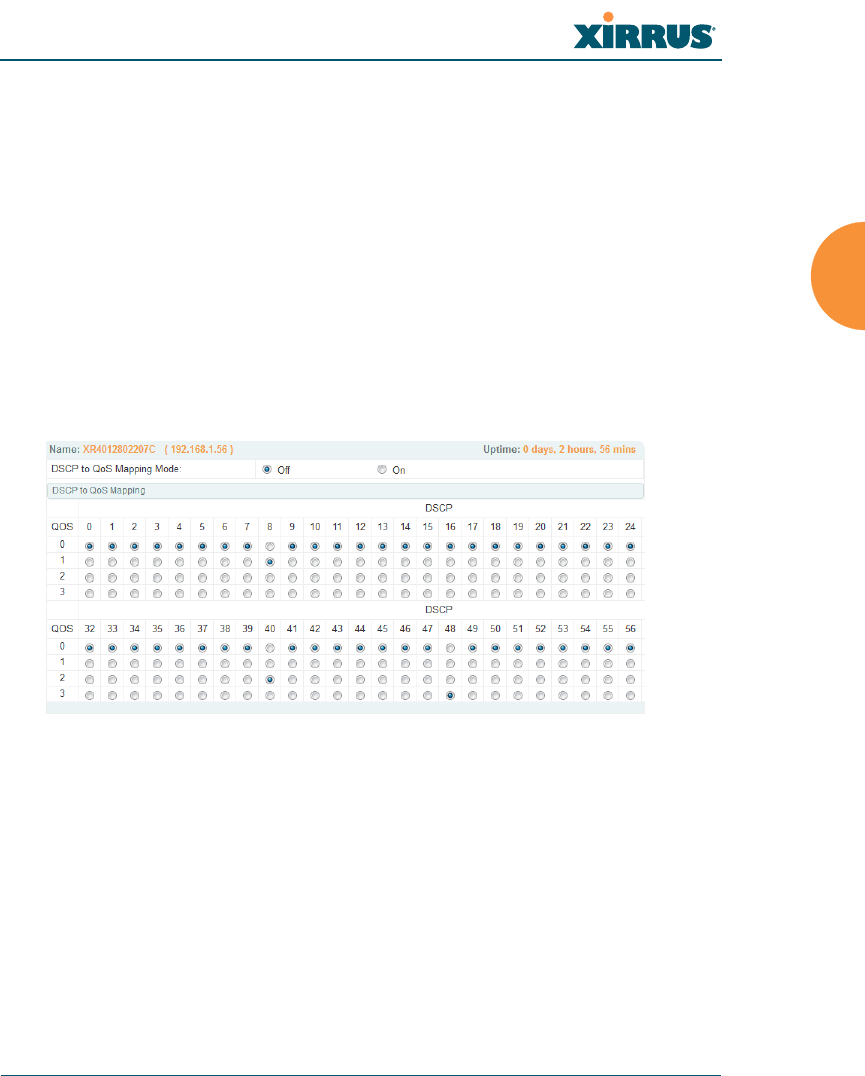
Wireless Array
Configuring the Wireless Array 335
DSCP Mappings
DSCP is the 6-bit Differentiated Services Code Point (DiffServ) field in the IPv4 or
IPv6 packet header, defined in RFC2474 and RFC2475. The DSCP value classifies
the packet to determine the Quality of Service (QoS) required. DSCP replaces the
outdated Type of Service (TOS) field.
The DSCP Mappings page shows the default mapping of each of the 64 DSCP
values to one of the Array’s four QoS levels, and allows you to change these
mappings.
For a detailed discussion of the operation of QoS and DSCP mappings on the
Array, please see “Understanding QoS Priority on the Wireless Array” on
page 244.
Figure 160. DSCP Mappings
Procedure for Configuring DSCP Mappings
1. DSCP to QoS Mapping Mode: Use the On and Off buttons to enable or
disable the use of the DSCP mapping table to determine the QoS level
applied to each packet.
2. DSCP to QoS Mapping: The radio buttons in this table show all DSCP
values (0 to 63), and the QoS level to which each is mapped. To change the
QoS level applied to a DSCP value, click the desired QoS level (0 to 3)
underneath it.

Wireless Array
336 Configuring the Wireless Array
Roaming Assist
Roaming assist is a Xirrus feature that helps clients roam to Arrays that will give
them high quality connections. Some smart phones and tablets will stay
connected to a radio with poor signal quality, even when there’s a radio with
better signal strength within range. When roaming assist is enabled, the Array
“assists” the device by deauthenticating it when certain parameters are met. This
encourages a client with a high roaming threshold (i.e., a device that may not
roam until signal quality has seriously dropped) to move to an Array that gives it
a better signal. The deauthentication is meant to cause the client to choose a
different radio. You can specify the device types that will be assisted in roaming.
The roaming threshold is the difference in signal strength between radios that will
trigger a deauthentication. If the client’s signal is lower than the sum of the
threshold and the stronger neighbor radio’s RSSI, then we “assist” the client. For
example:
Threshold = -5
RSSI of neighbor Array = -65
RSSI of client = -75
-75 < (-5 + -65) : Client will roam
Another example:
Threshold = -15
RSSI of neighbor array = -60
RSSI of station = -70
-70 > (-15 + -60) : Client will not roam
Procedure for Configuring Roaming Assist
1. Enable Roaming Assist: Use the Yes and No buttons to enable or disable
this feature.
2. Backoff Period: After deauthenticating a station, it may re-associate to
the same radio. To prevent the Array from repeatedly deauthenticating
the station when it comes back, there is a backoff period. This is the
number of seconds the station is allowed to stay connected before another
deauthentication.
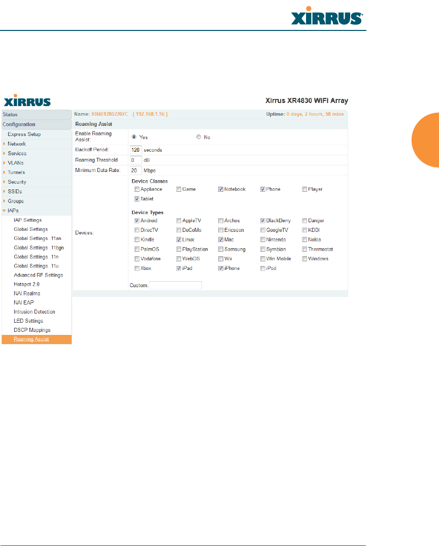
Wireless Array
Configuring the Wireless Array 337
3. Roaming Threshold: This is the difference in signal strength between
radios that will trigger a deauthentication, as described in the discussion
above. In most cases, this will be a negative number.
Figure 161. Roaming Assist
4. Minimum Data Rate: If the station’s data rate (either Tx or Rx) falls
below this rate, it will trigger a deauthentication.
5. Device Classes and Device Types: You can configure the device classes
or types that will be assisted in roaming. Many small, embedded devices
(such as the default device types: phones, tablets, music players) are
sticky—they have high roaming thresholds that tend to keep them
attached to the same radio despite the presence of radios with better
signal strength. You may check off one or more entries, but use care since
roaming assist may cause poor results in some cases.
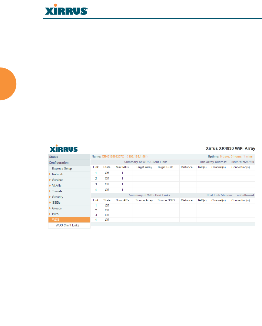
Wireless Array
338 Configuring the Wireless Array
WDS
This is a status-only window that provides an overview of all WDS links that have
been defined. WDS (Wireless Distribution System) is a system that enables the
interconnection of access points wirelessly, allowing your wireless network to be
expanded using multiple access points without the need for a wired backbone to
link them. The Summary of WDS Client Links shows the WDS links that you
have defined on this Array and identifies the target Array for each by its base
MAC address. The Summary of WDS Host Links shows the WDS links that have
been established on this Array as a result of client Arrays associating to this Array
(i.e., the client Arrays have this Array as their target). The summary identifies the
source (client) Array for each link. Both summaries identify the IAPs that are part
of the link and whether the connection for each is up or down. See “WDS
Planning” on page 53 for an overview.
Figure 162. WDS
About Configuring WDS Links
A WDS link connects a client Array and a host Array (see Figure 163 on page 339).
The host must be the Array that has a wired connection to the LAN. Client links
from one or more Arrays may be connected to the host, and the host may also
have client links. See “WDS Planning” on page 53 for more illustrations.
The configuration for WDS is performed on the client Array only, as described in
“WDS Client Links” on page 340. No WDS configuration is performed on the host
Array. First you will set up a client link, defining the target (host) Array and SSID,
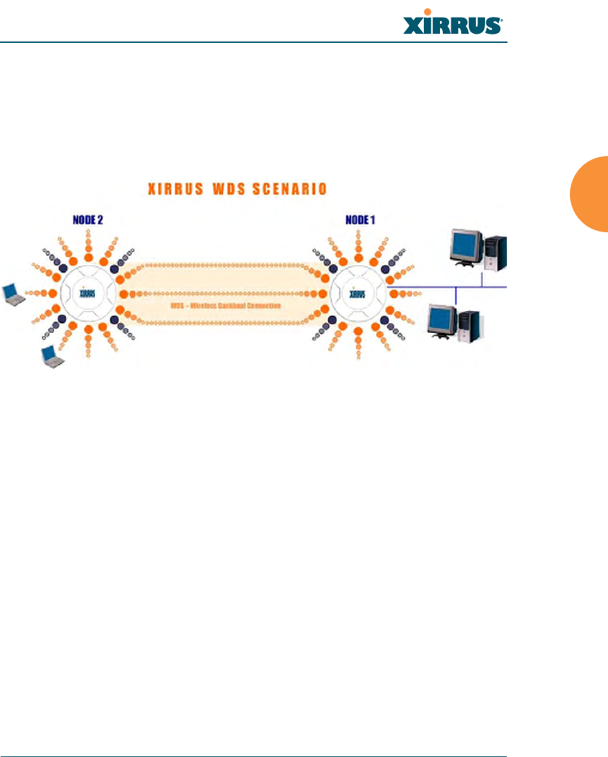
Wireless Array
Configuring the Wireless Array 339
and the maximum number of IAPs in the link. Then you will select the IAPs to be
used in the link. When the client link is created, each member IAP will associate to
an IAP on the host Array.
You may wish to consider configuring the WDS link IAPs so that only the WDS
link SSIDs are active on them. See “Active IAPs” on page 261.
Figure 163. Configuring a WDS Link
Long Distance Links
If you are using WDS to provide backhaul over an extended distance, use the
WDS Dist. (Miles) setting to prevent timeout problems associated with long
transmission times. (See “IAP Settings” on page 274) Set the approximate distance
Once an IAP has been selected to act as a WDS client link, you will not be
allowed to use auto-configured cell sizing on that IAP (since the cell must
extend all the way to the other Array).
When configuring WDS, if you use WPA-PSK (Pre-Shared Key) as a
security mechanism, ensure that EAP is disabled. Communication between
two Arrays in WDS mode will not succeed if the client Array has both PSK
and EAP enabled on the SSID used by WDS. See SSID Management.
TKIP encryption does not support high throughput rates, per IEEE 802.11n.
TKIP should never be used for WDS links on XR and XN arrays.
a2(52)
a3(149)
a4(40)
a10(52)
a9(149)
a8(40)
CLIENT HOST
Wired LAN
Client
Link
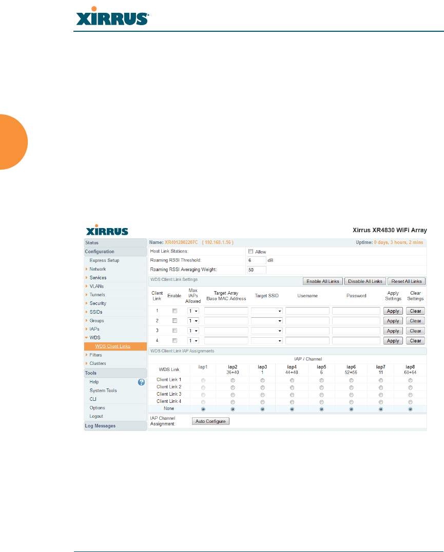
Wireless Array
340 Configuring the Wireless Array
in miles between this IAP and the connected Array in the WDS Dist. (Miles)
column. This will increase the wait time for frame transmission accordingly.
See Also
SSID Management
Active IAPs
WDS Client Link IAP Assignments:
WDS Client Links
WDS Statistics
WDS Client Links
This window allows you to set up a maximum of four WDS client links.
Figure 164. WDS Client Links

Wireless Array
Configuring the Wireless Array 341
Procedure for Setting Up WDS Client Links
WDS Client Link Settings:
1. Host Link Stations: Check the Allow checkbox to instruct the Array to
allow stations to associate to IAPs on a host Array that participates in a
WDS link. The WDS host IAP will send beacons announcing its
availability to wireless clients. This is disabled by default.
2. Spanning Tree Protocol (STP): Check the Enable checkbox to instruct the
Array to enforce the Spanning Tree Protocol on all WDS links. This is
enabled by default. Use of STP is strongly recommended in most
situations. However, in situations like the one in the next step, where
WDS is used by an Array mounted on a high speed train, STP can add
significant delay (often on the order of 30 to 60 seconds) while initially
analyzing network topology. In such a situation, it may be desirable to
disable STP.
3. Roaming RSSI Threshold: If an Array is deployed on a mobile site (on a
train, for example), you can use WDS to implement a wireless backhaul
that will roam between Arrays at fixed locations. When another
candidate Array for WDS host target is found, the client link will roam to
the new Array if its RSSI is stronger than the RSSI of the current host
connection by at least the Roaming RSSI Threshold. The default is 6 dB.
4. Roaming RSSI Averaging Weight: This weight changes how much the
latest RSSI reading influences the cumulative weighted RSSI value
utilized in checking the threshold (above) to make a roaming decision.
Once an IAP has been selected to act as a WDS client link, no other
association will be allowed on that IAP. However, wireless associations will
be allowed on the WDS host side of the WDS session.
Caution: If STP is disabled and a network connection is made on the WDS
Client Array’s Gigabit link that can reach the WDS Host Array, broadcast
and multicast packets will not be blocked. A broadcast storm may cause a
network outage.

Wireless Array
342 Configuring the Wireless Array
The higher the weight, the lower the influence of a new RSSI reading.
This is not exactly a percentage, but a factor in the formula for computing
the current RSSI value based on new readings:
StoredRSSI = (StoredRSSI * RoamingAvgWeight
+ NewRSSIReading * (100 - RoamingAvgWeight)) / 100
This prevents erroneous or out-of-line RSSI readings from causing the
WDS link to jump to a new array. Such readings can result from
temporary obstructions, external interference, etc.
5. Click Save changes to flash after you are finished making changes on this
page if you wish to make your changes permanent.
WDS Client Link IAP Setting:
6. Enable/Disable/Reset All Links: Click the appropriate button to:
•Enable All Links—this command activates all WDS links configured
on the Array.
•Disable All Links—this command deactivates all WDS links
configured on the Array. It leaves all your settings unchanged, ready
to re-enable.
•Reset All Links—this command tears down all links configured on
the Array and sets them back to their factory defaults, effective
immediately.
7. Client Link: Shows the ID (1 to 4) of each of the four possible WDS links.
8. Enabled: Check this box if you want to enable this WDS link, or uncheck
the box to disable the link.
9. Max IAPs Allowed (1-3): Enter the maximum number of IAPs for this
link, between 1 and 3.
10. Target Array Base MAC Address: Enter the base MAC address of the
target Array (the host Array at the other side of this link). To find this
MAC address, open the WDS window on the target Array, and use This
Array Address located on the right under the Summary of WDS Host

Wireless Array
Configuring the Wireless Array 343
Links. To allow any Xirrus Array to be accepted as a WDS target, enter the
Xirrus OUI: 00:0f:7d:00:00:00 (this is useful for roaming in a mobile
deployment, as described in Step 3 on page 341.
11. Target SSID: Enter the SSID that the target Array is using.
12. Username: Enter a username for this WDS link. A username and
password is required if the SSID is using PEAP for WDS authentication
from the internal RADIUS server.
13. Password: Enter a password for this WDS link.
14. Clear Settings: Click on the Clear button to reset all of the fields on this
line.
WDS Client Link IAP Assignments:
15. For each desired client link, select the IAPs that are part of that link. The
IAP channel assignments are shown in the column headers.
16. IAP Channel Assignment: Click Auto Configure to instruct the Array to
automatically determine the best channel allocation settings for each IAP
that participates in a WDS link, based on changes in the environment.
These changes are executed immediately, and are automatically applied.
See Also
SSID Management
WDS Planning
WDS
WDS Statistics
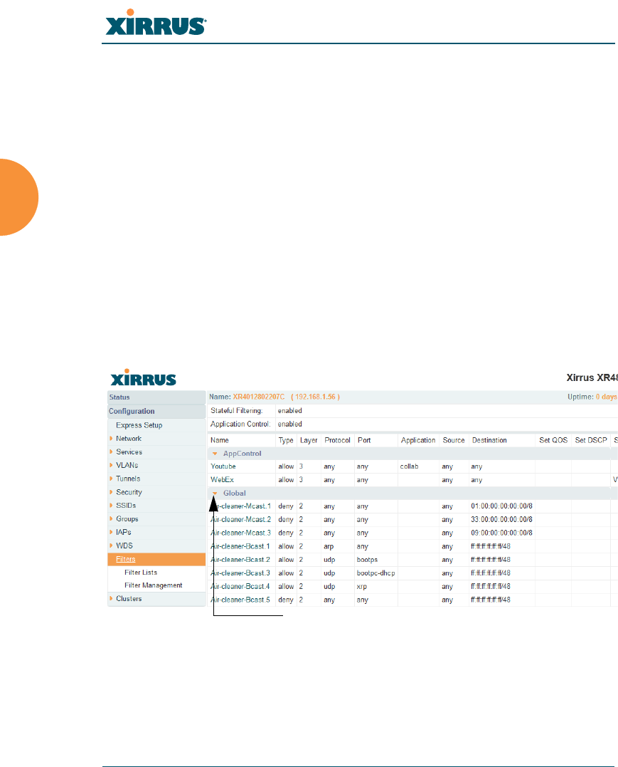
Wireless Array
344 Configuring the Wireless Array
Filters
The Wireless Array’s integrated firewall uses stateful inspection to speed the
decision of whether to allow or deny traffic. Filters are used to define the rules
used for blocking or passing traffic. Filters can also set the VLAN and QoS level
for selected traffic.
Figure 165. Filters
User connections managed by the firewall are maintained statefully — once a user
flow is established through the Array, it is recognized and passed through
This feature is only available if the Array’s license includes the Xirrus
Advanced RF Security Manager (RSM). If a setting is unavailable
(grayed out), then your license does not support the feature. Please see
“About Licensing and Upgrades” on page 361.
The air cleaner feature offers a number of predetermined filter rules that
eliminate a great deal of unnecessary wireless traffic. See “Air Cleaner” on
page 403.
Orange arrow
expands/collapses display
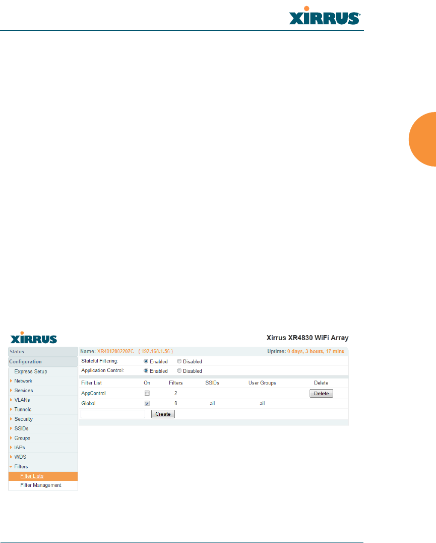
Wireless Array
Configuring the Wireless Array 345
without application of all defined filtering rules. Stateful inspection runs
automatically on the Array. The rest of this section describes how to view and
manage filters.
Filters are organized in groups, called Filter Lists. A filter list allows you to apply
a uniform set of filters to SSIDs or Groups very easily.
The read-only Filters window provides you with an overview of all filter lists that
have been defined for this Array, and the filters that have been created in each list.
Filters are listed in the left side column by name under the filter list to which they
belong. Each filter entry is a link that takes you to its Filter Management entry,
and the list includes information about the type of filter, the protocol it is filtering,
which port it applies to, source and destination addresses, and QoS and VLAN
assignments.
Filter Lists
This window allows you to create filter lists. The Array comes with one
predefined list, named Global, which cannot be deleted. Filter lists (including
Global) may be applied to SSIDs or to Groups. Only one filter list at a time may be
applied to a group or SSID (although the filter list may contain a number of
filters). All filters are created within filter lists.
Figure 166. Filter Lists

Wireless Array
346 Configuring the Wireless Array
Procedure for Managing Filter Lists
1. Stateful Filtering: Stateful operation of the integrated firewall can be
Enabled or Disabled. If you have a large number of filters and you don’t
want to apply them in a stateful manner, you may use this option to turn
the firewall off.
2. Application Control: Operation of the Application Control feature may
be Enabled or Disabled. See “Application Control Windows” on
page 150.
3. New Filter List Name: Enter a name for the new filter list in this field,
then click on the Create button to create the list. All new filters are
disabled when they are created. The new filter list is added to the Filter
List table in the window. Click on the filter list name, and you will be
taken to the Filter Management window for that filter list.
4. On: Check this box to enable this filter list, or leave it blank to disable the
list. If the list is disabled, you may still add filters to it or modify it, but
none of the filters will be applied to data traffic.
5. Filters: This read-only field displays the number of filters that belong to
this filter list.
6. SSIDs: This read-only field lists the SSIDs that use this filter list.
7. User Groups: This read-only field lists the Groups that use this filter list.
8. Delete: Click this button to delete this filter list. The Global filter list may
not be deleted.
The Application Control feature is only available if the Array license
includes Application Control. If a setting is unavailable (grayed out), then
your license does not support the feature. See “About Licensing and
Upgrades” on page 361.
Application Control data is only available from XR Series Array models. It
is not available on XN Arrays.
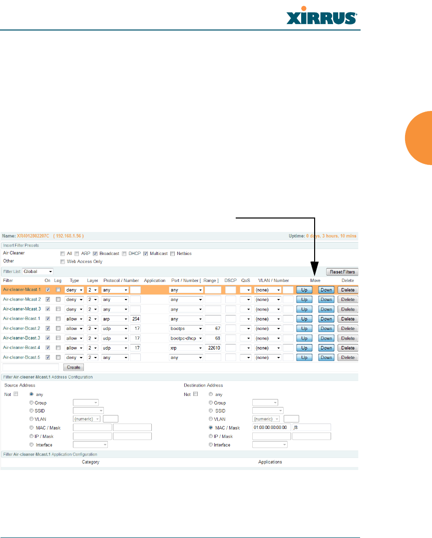
Wireless Array
Configuring the Wireless Array 347
9. Click Save changes to flash if you wish to make your changes
permanent.
10. Click a filter list to go to the Filter Management window to create and
manage the filters that belong to this list.
Filter Management
This window allows you to create and manage filters that belong to a selected
filter list, based on the filter criteria you specify. Filters are an especially powerful
feature when combined with the intelligence provided by the “Application
Control Windows” on page 150.
Figure 167. Filter Management
Filters are applied in order, from top to bottom.
Click here to change the order.

Wireless Array
348 Configuring the Wireless Array
Based on Application Control’s analysis of your wireless traffic, you can create
filters to enhance wireless usage for your business needs:
Usage of non-productive and risky applications like BitTorrent can be
restricted.
Traffic for mission-critical applications like VoIP and WebEx may be given
higher priority (QoS).
Non- critical traffic from applications like YouTube may be given lower
priority (QoS).
Traffic flows for specific applications may be controlled by sending them
into VLANs that are designated for that type of traffic.
Note that filtering is secondary to the stateful inspection performed by the
integrated firewall. Traffic for established connections is passed through without
the application of these filtering rules.
Procedure for Managing Filters
1. Filter List: Select the filter list to display and manage on this window. All
of the filters already defined for this list are shown, and you may create
additional filters for this list.
2. Add Preset Filter: A number of predefined “Air Cleaner” filters are
available using these buttons. You can use these rules to eliminate a great
deal of unnecessary wireless traffic, resulting in improved performance.
For more information, please see “Air Cleaner” on page 403.
3. New Filter Name: To add a new filter, enter its name in the field next to
the Create button at the bottom of the list, then click Create. All new
filters are added to the table of filters in the window. The filter name must
be unique within the list, but it may have the same name as a filter in a
different filter list. Two filters with the same name in different filter lists
will be completely unrelated to each other — they may be defined with
different parameter values.
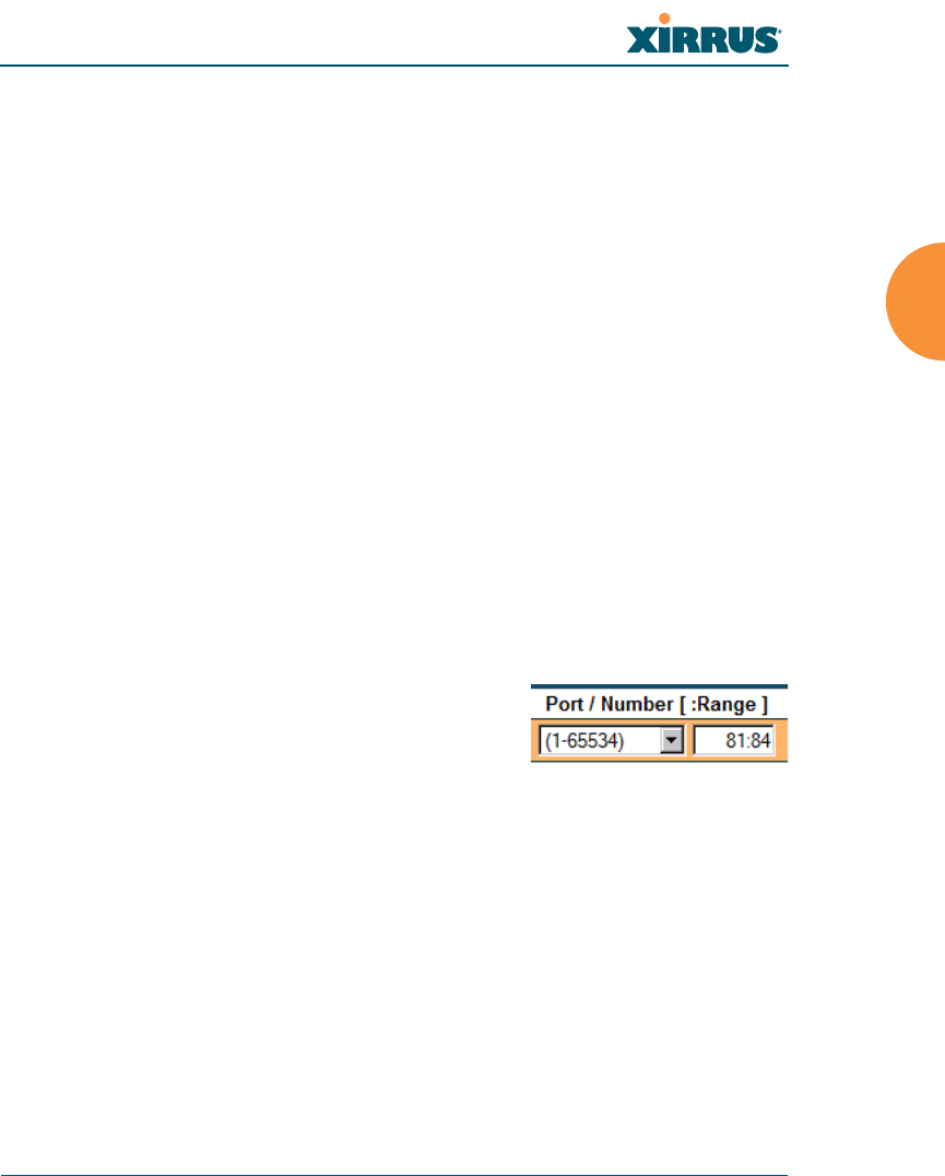
Wireless Array
Configuring the Wireless Array 349
Viewing or modifying existing filter entries:
4. Filter: Select a filter entry if you wish to modify it. Source and destination
details are displayed below the bottom of the list.
5. On: Use this field to enable or disable this filter.
6. Log: Log usage of this filter to Syslog.
7. Type: Choose whether this filter will be an Allow filter or a Deny filter. If
you define the filter as an Allow filter, then any associations that meet the
filter criteria will be allowed. If you define the filter as a Deny filter, any
associations that meet the filter criteria will be denied.
8. Layer: Select network layer 2 or 3 for operation of this filter.
9. Protocol/Number: Choose a specific filter protocol from the pull-down
list, or choose numeric and enter a Number, or choose any to instruct the
Array to use the best filter. This is a match criterion.
10. Port/Number: This is a match criterion. From the pull-down list, choose
the target port type for this filter. Choose any to instruct the Array to
apply the filter to any port, or choose 1-65534 and enter a Number.
To enter a Range of port numbers,
separate the start and end numbers with
a colon as shown: Start # : End #.
11. QoS: (Optional) Set packets that match the filter criteria to this QoS level
(0 to 3), selected from the pull-down list. Level 0 has the lowest priority;
level 3 has the highest priority. By default, this field is blank and the filter
does not modify QoS level. See “Understanding QoS Priority on the
Wireless Array” on page 244.
12. VLAN/Number: (Optional) Set packets that match the filter criteria to
this VLAN. Select a VLAN from the pull-down list, or select numeric and
enter the number of a previously defined VLAN (see “VLANs” on
page 199).

Wireless Array
350 Configuring the Wireless Array
13. Move Up/Down: The filters are applied in the order in which they are
displayed in the list, with filters on the top applied first. To change an
entry’s position in the list, just click its Up or Down button.
14. To delete a filter, click its Delete button.
Select an existing filter entry in the list to view or modify the following, shown
below the list of filters:
15. Source Address: Define a source address to match as a filter criterion.
Click the radio button for the desired type of address (or other attribute)
to match. Then specify the value to match in the field to the right of the
button. Choose Any to use any source address. Check Not to match any
address except for the specified address.
16. Destination Address: Define a destination address to match as a filter
criterion. Click the radio button for the desired type of address (or other
attribute) to match. Then specify the value to match in the field to the
right of the button. Choose any to use any source address. Check Not to
match any address except for the specified address.
Below the Source and Destination Addresses, you may enter a Category or an
Application to be matched by the filter:
17. Category: If you wish this filter to apply to a particular category of
application, such as File-Transfer or Database, select it from the listed
options.
Figure 168. Filter Category or Application

Wireless Array
Configuring the Wireless Array 351
18. Applications: If you wish this filter to apply to a specific application,
such as WebEx, click the letter or number that it starts with. Then select
the desired application. You may select a Category or an Application, but
not both.
19. Click Save changes to flash if you wish to make your changes
permanent.
See Also
Filters
Filter Statistics
Understanding QoS Priority on the Wireless Array
VLANs

Wireless Array
352 Configuring the Wireless Array
Clusters
Clusters allow you to configure multiple Arrays at the same time. Using WMI (or
CLI), you may define a set of Arrays that are members of the cluster. Then you
may enter Cluster mode for a selected cluster, which sends all successive
configuration commands issued via CLI or WMI to all of the member Arrays.
When you exit cluster mode, configuration commands revert to applying only to
the Array to which you are connected.
The read-only Clusters window provides you with an overview of all clusters that
have been defined for this Array, and the Arrays that have been added to each.
Arrays are listed in the left hand column by name under the cluster to which they
belong. Each Array entry displays its IP Address, Username, and Password.
Figure 169. Clusters
Clusters are discussed in the following topics:
Cluster Definition
Cluster Management
Cluster Operation
This feature is not avialable on XR500 Series Arrays.

Wireless Array
Configuring the Wireless Array 353
Cluster Definition
This window allows you to create clusters. All existing clusters are shown, along
with the number of Arrays currently in each. Up to 16 clusters may be created,
with up to 50 Arrays in each.
Figure 170. Cluster Definition
Procedure for Managing Cluster Definition
1. New Cluster Name: Enter a name for the new cluster in the field to the
left of the Create button, then click Create to add this entry. The new
cluster is added to the list in the window. Click on the cluster name, and
you will be taken to the Cluster Management window for that cluster.
2. Delete: To delete a cluster, click its Delete button.
3. Click Save changes to flash if you wish to make your changes
permanent.
4. Click a cluster to go to the Cluster Management window to add or
remove Arrays in the cluster.

Wireless Array
354 Configuring the Wireless Array
Cluster Management
This window allows you to add Arrays to or delete them from a selected cluster.
A cluster may include a maximum of 50 Arrays.
Note that the Array on which you are currently running WMI is not automatically
a member of the cluster. If you would like it to be a member, you must add it
explicitly.
Figure 171. Cluster Management
Procedure for Managing Clusters
1. Edit Cluster: Select the cluster to display and manage on this window. All
of the Arrays already defined for this cluster are shown, and you may
add additional Arrays to this list.
2. Array: Enter the hostname or IP address of the Array that you wish to
add to this cluster.
3. Username/Password: In these columns, enter the administrator name
and password for access to the Array.
4. Click the Add Array button to enter the Array.
5. To delete an Array, click its Delete button.
6. Click Save changes to flash if you wish to make your changes
permanent.

Wireless Array
Configuring the Wireless Array 355
Cluster Operation
This window puts WMI into Cluster Mode. In this mode, all configuration
operations that you execute in WMI or CLI are performed on the members of the
cluster. They are not performed on the Array where you are running WMI, unless
it is a member of the cluster.
You must use the Save changes to flash button at the top of configuration
windows to permanently save your changes in Cluster Mode, just as you would
in normal operation. When you are done configuring Arrays in the cluster, return
to this window and click the Exit button to leave Cluster Mode.
Figure 172. Cluster Mode Operation
Procedure for Operating in Cluster Mode
1. Operate: Click the Operate button to the right of the desired cluster. A
message informs you that you are operating in cluster mode. Click OK.
The Operate button is replaced with an Exit button.
Figure 173. Cluster Mode Activation
An XR-1000 Series Array cannot act as the Cluster controller. It will
operate correctly as a member of a cluster.
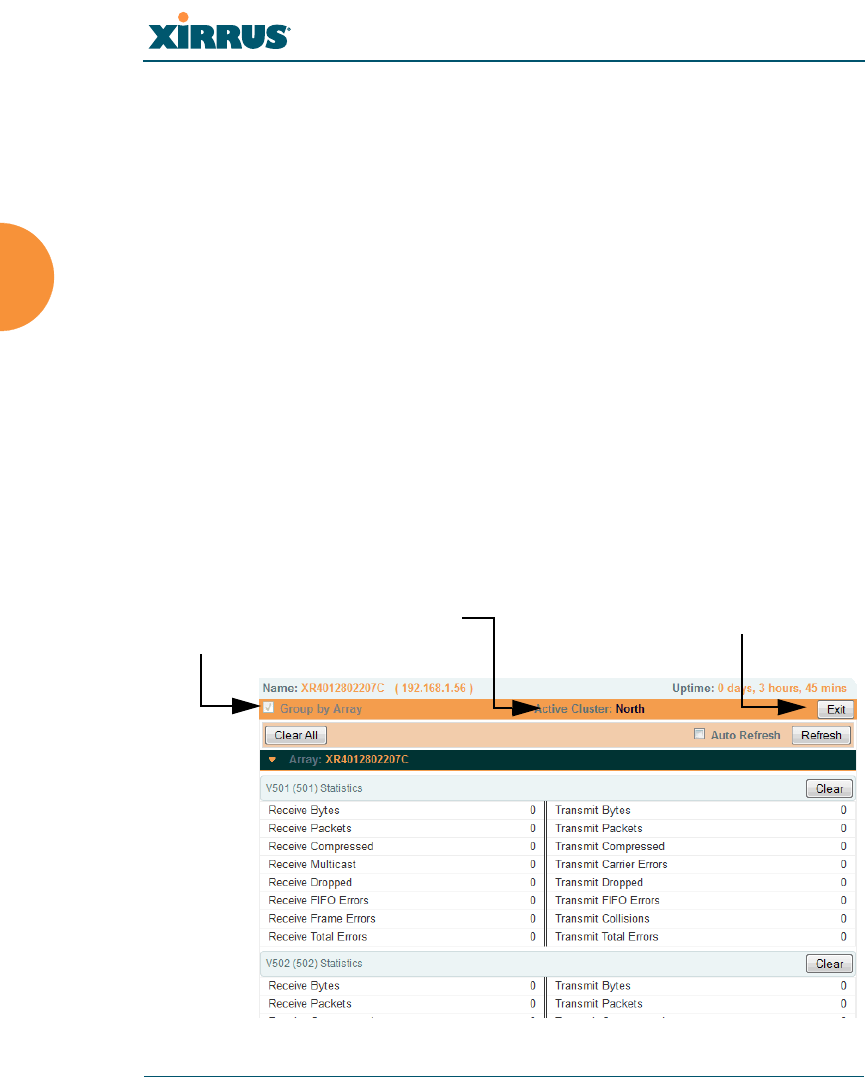
Wireless Array
356 Configuring the Wireless Array
2. Select a WMI window for settings that you wish to configure for the
cluster, and proceed to make the desired changes.
3. Proceed to any additional pages where you wish to make changes.
4. Some Status and Statistics windows will present information for all
Arrays in the cluster.
5. Click the Save button when done if you wish to save changes on the
cluster member Arrays.
6. Exit: Click the Exit button to the right of the operating cluster to terminate
Cluster Mode. The WMI returns to normal operation — managing only
the Array to which it is connected.
Status and Statistics Windows in Cluster Mode
In Cluster Mode, many of the Status and Statistics windows will display
information for all of the members of the cluster. You can tell whether a window
displays cluster information — if so, it will display the Cluster Name near the top,
as shown in Figure 174.
Figure 174. Viewing Statistics in Cluster Mode
Cluster Name
Specify Grouping
Exit Cluster Mode

Wireless Array
Configuring the Wireless Array 357
You have the option to show aggregate information for the cluster members, or
click the Group by Array check box to separate it out for each Array.
You may terminate cluster mode operation by clicking the Exit button to the right
of the Group by Array check box.

Wireless Array
358 Configuring the Wireless Array

Wireless Array
Using Tools on the Wireless Array 359
Using Tools on the Wireless
Array
These WMI windows allow you to perform administrative tasks on your Array,
such as upgrading software, rebooting, uploading and downloading
configuration files, and other utility tasks. Tools are described in the following
sections:
“System Tools” on page 360
“CLI” on page 371
“Options” on page 373
“Logout” on page 376
Note that the Tool s menu section may be collapsed down to hide the headings
under it by clicking it. Click again to display the headings. (See Figure 43 on
page 89)
This section does not discuss using status or configuration windows. For
information on those windows, please see:
“Viewing Status on the Wireless Array” on page 95
“Configuring the Wireless Array” on page 159
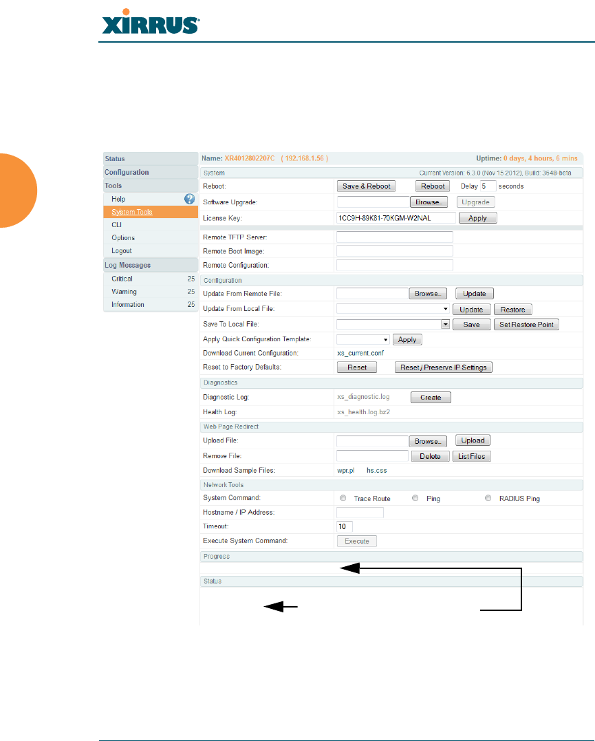
Wireless Array
360 Using Tools on the Wireless Array
System Tools
This window allows you to manage files for software images, configuration, and
Web Page Redirect (WPR), manage the system’s configuration parameters, reboot
the system, and use diagnostic tools.
Figure 175. System Tools
Status is
shown here
Progress is
shown here

Wireless Array
Using Tools on the Wireless Array 361
About Licensing and Upgrades
The Array’s license determines many of the features that are available on the
Array. For example, automatic cell sizing and channel allocation require a license
that includes the Xirrus Advanced RF Performance Manager (RPM). Also, IEEE
802.11n operation on XN model Arrays is a licensed feature. To check the features
supported by your license, see “Array Information” on page 101.
If you are upgrading the Array to add new features that are not supported by
your existing license, you must enter the new license key that includes the
upgrade’s features before upgrading.
Similarly, if you are upgrading the Array for a new release, you must enter the
new license key that enables the operation of that release before upgrading. If you
do not enter the new license first, the Array will display a message and revert to
the previous software image, rather than trying to run new software for which it
is not licensed. Major releases will need a new license key, but minor releases will
not. For example, to upgrade from ArrayOS Release 5.0.5 to Release 5.1, you must
enter a new license key. To upgrade from ArrayOS Release 5.0.5 to Release 5.0.6,
use your existing license key.
If you will be entering license keys and performing upgrades on many Arrays, the
effort will be streamlined by using the Xirrus Management System (XMS).
Procedure for Configuring System Tools
These tools are broken down into the following sections:
System
Configuration
Diagnostics
Web Page Redirect
Some tools, such as Network Tools and Diagnostics, are only available if the
Array’s license includes the Xirrus Advanced RF Analysis Manager
(RAM). If a tool is unavailable (grayed out), then your license does not
support the feature. See “About Licensing and Upgrades” on page 361.

Wireless Array
362 Using Tools on the Wireless Array
Network Tools
Progress and Status Frames
System
1. Save & Reboot or Reboot: Use Save & Reboot to save the current
configuration and then reboot the Array. The LEDs on the Array indicate
the progress of the reboot, as described in “Powering Up the Wireless
Array” on page 63. Alternatively, use the Reboot button to discard any
configuration changes which have not been saved since the last reboot.
You may specify an optional Delay period in seconds to wait before the
reboot starts.
2. Software Upgrade: This feature upgrades the ArrayOS to a newer
version provided by Xirrus. Please note that you typically will need to
enter a new license key to cover the upgrade’s features before clicking
the Upgrade button. See “About Licensing and Upgrades” on page 361
for details.
Enter the filename and directory location (or click on the Browse button
to locate the software upgrade file), then click on the Upgrade button to
upload the new file to the Array. Progress of the operation will be
displayed below, in the Progress section. Completion status of the
operation is shown in the Status section.
This operation does not run the new software or change any configured
values. The existing software continues to run on the Array until you
reboot, at which time the uploaded software will be used.
If you have difficulty upgrading the Array using the WMI, see “Upgrading
the Array via CLI” on page 464 for a lower-level procedure you may use.
Software Upgrade always uploads the file in binary mode. If you transfer
any image file to your computer to have it available for the Software Upgrade
command, it is critical to remember to transfer it (ftp, tftp) in binary mode!

Wireless Array
Using Tools on the Wireless Array 363
3. License Key: If Xirrus provides you with a new license key for your
Array, use this field to enter it, then click the Apply button to the right. A
valid license is required for Array operation, and it controls the features
available on the Array. If you upgrade your Array for additional features,
you will be provided with a license key to activate those capabilities.
If you attempt to enter an invalid key, you will receive an error message
and the current key will not be replaced.
Automatic Updates from Remote Image or Configuration File
The Array software image or configuration file can be downloaded from an
external server. In large deployments, all Arrays can be pointed to one TFTP
server instead of explicitly initiating software image uploads to all Arrays. When
the Array boots, the Array will download the software image from the specified
TFTP server. Similarly, if you decide to change a setting in the Arrays, you can
simply modify a single configuration file. After the Arrays are rebooted, they will
automatically download the new configuration file from a single location on the
specified TFTP server.
4. Remote TFTP Server: This field defines the path to a TFTP server to be
used for automated remote update of software image and configuration
files when rebooting. You may specify the server using an IP address or
host name.
5. Remote Boot Image: When the Array boots up, it fetches the software
image file specified here from the TFTP server defined above, and
upgrades to this image before booting. This must be an Array image file
with a .bin extension.
Make sure to place the file on the TFTP server. If you disable the remote
boot image (by blanking out this field) or if the image can't be transferred,
the Array will fall back to booting whatever image is on the compact
flash.

Wireless Array
364 Using Tools on the Wireless Array
6. Remote Configuration: When the Array boots up, it fetches the specified
configuration file from the TFTP server defined above, and applies this
configuration after the local configuration is applied. The remote
configuration must be an Array configuration file with a .conf extension.
Make sure to place the file on the TFTP server.
A partial configuration file may be used. For instance, if you wish to use a
single configuration file for all of your Arrays but don't want to have the
same IP address for each Array, you may remove the ipaddr line from the
file. You can then load the file on each Array and the local IP addresses
will not change.
A remote configuration is never saved to the compact flash unless you
issue a Save command.
Configuration
7. Update from Remote File: This field allows you to define the path to a
configuration file (one that you previously saved — see Step 9 and Step 10
below). Click on the Browse button if you need to browse for the location
of the file, then click Update to update your configuration settings.
8. Update from Local File: This field updates Array settings from a local
configuration file on the Array. Select one of the following files from the
drop-down list:
•factory.conf: The factory default settings.
•lastboot.conf: The setting values from just before the last reboot.
•saved.conf: The last settings that were explicitly saved using the Save
changes to flash button at the top of each window.
The Remote Boot Image or Configuration update happens every time that the
Array reboots. If you only want to fetch the remote image or configuration
file one time, be sure to turn off the remote option (blank out the field on the
System Tools page) after the initial download. When a remote boot image is
used, the image is transferred directly into memory and is never written to
the compact flash.

Wireless Array
Using Tools on the Wireless Array 365
•history/saved-yyyymmdd-pre-update.conf:
history/saved-yyyymmdd-post-update.conf:
Two files are saved for an upgrade: the setting values from just before
an upgrade was performed, and the initial values afterward.
The filename includes the upgrade date.
•history/saved-yyyymmdd-auto.conf: Each time you use the Save
changes to flash button, an “auto” file is saved with the settings
current at that time.
•history/saved-yyyymmdd-pre-reset.conf:
history/saved-yyyymmdd-post-reset.conf:
Each time you use one of the Reset to Factory Default buttons, two
files are saved: the setting values from just before the reset, and the
initial values afterward. The filename includes the reset date.
•history/saved-yyyymmdd-hhmm.conf: The setting values that were
explicitly saved using the Set Restore Point button (see Step 9
below).
Click Update to update your configuration settings. Note that the History
folder allows a maximum of 16 files. The oldest file is automatically
deleted to make room for each new file.
9. Save to Local File: There are a few options for explicitly requesting the
Array to save your current configuration to a file on the Array:
•To view the list of configuration files currently on the Array, click the
down arrow to the right of this field. If you wish to replace one of
these files (i.e., save the current configuration under an existing file
name), select the file, then click Save. Note that you cannot save to
the file names factory.conf, lastboot.conf, and saved.conf - these files
are write-protected.
•You may enter the desired file name, then click Save.
•Click Set Restore Point to save a copy of the current configuration,
basing the file name on the current date and time. For example:
history/saved-20100318-1842.conf

Wireless Array
366 Using Tools on the Wireless Array
Note that the configuration is automatically saved to a file in a few
situations, as described in Step 8 above.
10. Download Current Configuration: Click on the link titled
xs_current.conf to download the Array’s current configuration settings to
a file (that you can upload back to the Array at a later date). The system
will prompt you for a destination for the file. The file will contain the
Array’s current configuration values.
11. Reset to Factory Defaults: Click on the Reset/Preserve IP Settings button
to reset the system’s current configuration settings to the factory default
values, except for the Array’s management IP address which is left unchanged.
This function allows you to maintain management connectivity to the
Array even after the reset. This will retain the Gigabit Ethernet port’s IP
address (see “Network Interfaces” on page 171), or if you have
configured management over a VLAN it will maintain the management
VLAN’s IP address (see “VLAN Management” on page 201). All other
previous configuration settings will be lost.
Click Reset to reset all of the system’s current configuration settings to
the factory default values, including the management IP address — all
previous configuration settings will be lost. The Array’s Gigabit Ethernet
ports default to using DHCP to obtain an IP address.
Diagnostics
12. Diagnostic Log: Click the Create button to save a snapshot of Array
information for use by Xirrus Customer Support personnel. The Progress
and Status Frames show the progress of this operation. When the process
Important! When you have initially configured your Array, or have made
significant changes to its configuration, we strongly recommend that you
save the configuration to a file in order to have a safe backup of your working
configuration.
If the IP settings change, the connection to the WMI may be lost.
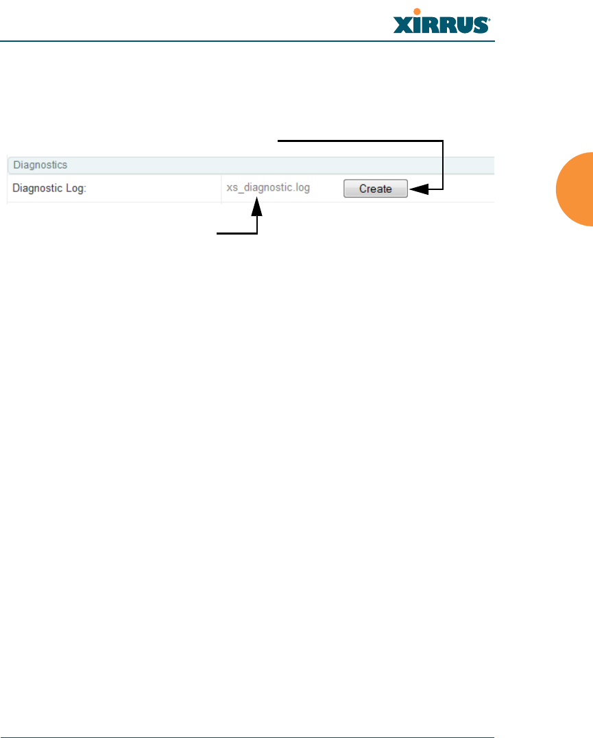
Wireless Array
Using Tools on the Wireless Array 367
is complete, the filename xs_diagnostic.log will be displayed in blue
and provides a link to the newly created log file. Click the link to
download this file to the C:\ folder on your local computer. (Figure 176)
Figure 176. Saving the Diagnostic Log
This feature is only used at the request of Customer Support. It saves all
of the information regarding your Array, including status, configuration,
statistics, log files, and recently performed actions.
The diagnostic log is always saved as a file named xs_diagnostic.log
on your C:\ drive, so you should immediately rename the file to save it.
This way, it will not be lost the next time you save a diagnostic log. Often,
Customer Support will instruct you to save two diagnostic logs about ten
minutes apart so that they can examine the difference in statistics
between the two snapshots (for example, to see traffic and error statistics
for the interval). Thus, you must rename the first diagnostic log file.
All passwords are stored on the array in an encrypted form and will not be
exposed in the diagnostic log.
Click Create to create log
Then click this link to save
log file to local computer
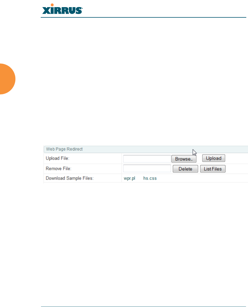
Wireless Array
368 Using Tools on the Wireless Array
Web Page Redirect
The Array uses a Perl script and a cascading style sheet to define the default
splash/login Web page that the Array delivers for WPR. You may replace
these files with files for one or more custom pages of your own. See Step 15
below to view the default files. See Step 14 on page 253 for more information
about WPR and how the splash/login page is used.
Each SSID that has WPR enabled may have its own page. Custom files for a
specific SSID must be named based on the SSID name. For example, if the
SSID is named Public, the default wpr.pl and hs.css files should be
modified as desired and renamed to wpr-Public.pl and hs-Public.css
before uploading to the Array. If you modify and upload files named wpr.pl
and hs.css, they will replace the factory default files and will be used for any
SSID that does not have its own custom files, per the naming convention just
described. Be careful not to replace the default files unintentionally.
Figure 177. Managing WPR Splash/Login page files
13. Upload File: Use this to install files for your own custom WPR splash/
login page (as described above) on the Array. Note that uploaded files are
not immediately used - you must reboot the Array first. At that time, the
Array looks for and uses these files, if found.
Enter the filename and directory location (or click Browse to locate the
splash/login page files), then click on the Upload button to upload the
new files to the Array. You must reboot to make your changes take effect.
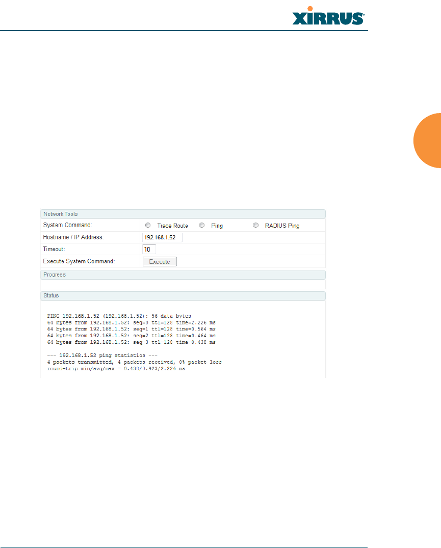
Wireless Array
Using Tools on the Wireless Array 369
14. Remove File: Enter the name of the WPR file you want to remove, then
click on the Delete button. You can use the List Files button to show you
a list of files that have been saved on the Array for WPR. The list is
displayed in the Status section at the bottom of the WMI window. You
must reboot to make your changes take effect.
15. Download Sample Files: Click on a link to access the corresponding
sample WPR files:
•wpr.pl — a sample Perl script.
•hs.css — a sample cascading style sheet.
Network Tools
Figure 178. System Command (Ping)
16. System Command: Choose Trace Route, Ping., or RADIUS Ping. For
Trace Route and Ping, fill in IP Address and Timeout. Then click the
Execute button to run the command.
The RADIUS Ping command is a simple utility that tests connectivity to a
RADIUS server by attempting to log in with the specified Username and
Password. When using a RADIUS server, this command allows you to
verify that the server configuration is correct and whether a particular
Username and Password are set up properly. If a client is having trouble
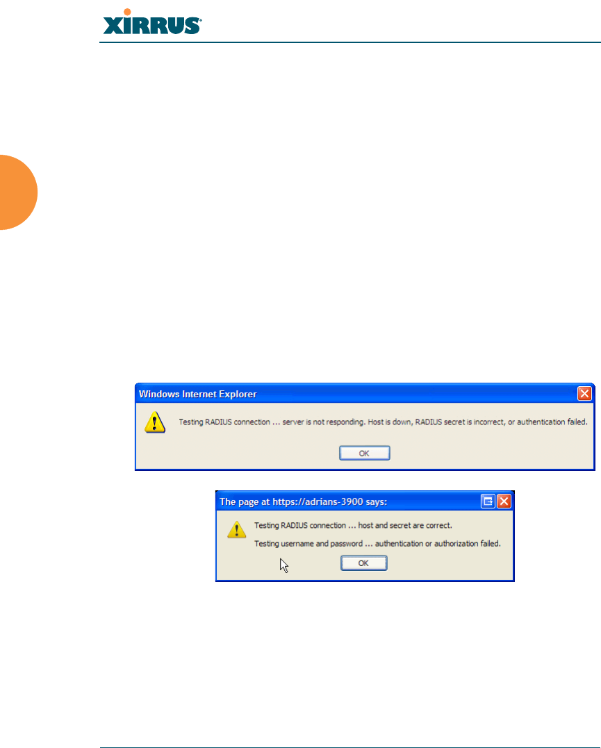
Wireless Array
370 Using Tools on the Wireless Array
accessing the network, you can quickly determine if there is a basic
RADIUS problem by using the RADIUS Ping tool. For example, in
Figure 179 (A), RADIUS Ping is unable to contact the server. In Figure 179
(B), RADIUS Ping verifies that the host information and secret for a
RADIUS server are correct, but that the user account information is not.
Select RADIUS allows you to select a RADIUS server that you have
already configured. When you make a choice in this field, additional
fields will be displayed. Set Select RADIUS to External Radius, Internal
Radius, or a server specified for a particular SSID, or select Other Server
to specify another server by entering its Host name or IP address, Port,
and shared Secret.
Enter the RADIUS Credentials: Username and Password. Select the
Authentication Type, PAP or CHAP. Click the Execute button to run the
command. The message Testing RADIUS connection appears. Click OK
to proceed.
Figure 179. Radius Ping Output
17. IP Address: For Ping or Trace Route, enter the IP address of the target
device.
18. Timeout: For Ping or Trace Route, enter a value (in seconds) before the
action times out.
A
B
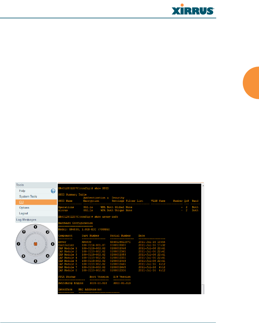
Wireless Array
Using Tools on the Wireless Array 371
19. Execute System Command: Click Execute to start the specified
command. Progress of command execution is displayed in the Progress
frame. Results are displayed in the Status frame.
Progress and Status Frames
The Progress frame displays a progress bar for commands such as Software
Upgrade and Ping. The Status frame presents the output from system
commands (Ping and Trace Route), as well as other information, such as the
results of software upgrade.
20. If you want to save the parameters you established in this window for
future sessions, click on the Save changes to flash button.
CLI
The WMI provides this window to allow you to use the Array’s Command Line
Interface (CLI). You can enter commands to configure the Array, or display
information using show commands. You will not need to log in - you already
logged in to the Array when you started the WMI.
Figure 180. CLI Window

Wireless Array
372 Using Tools on the Wireless Array
To enter a command, simply type it in. The command is echoed and output is
shown in the normal way — that is, the same way it would be if you were using
the CLI directly. You may use the extra scroll bar inside the right edge of the
window to scroll through your output. If output runs past the right edge of the
screen, there is also a horizontal scroll bar at the bottom of the page.
This window has some minor differences, compared to direct use of the CLI via
the console or an SSH connection:
The CLI starts in config mode. All configuration and show commands are
available in this mode. You can “drill down” the mode further in the
usual way. For example, you can type interface iap to change the mode to
config-iap. The prompt will indicate the current command mode, for
example:
My-Array(config-iap) #
You can abbreviate a command and it will be executed if you have typed
enough of the command to be unambiguous. The command will not
auto-complete, however. Only the abbreviated command that you
actually typed will be shown. You can type a partial command and press
Tab to have the command auto-complete. If the partial command is
ambiguous a list of legal endings is displayed.
Entering quit will return you to the previously viewed WMI page.
Most, but not all, CLI commands can be run in this window. Specifically
the run-test menu of commands is not available in this window. To use
the run-test command, please connect using SSH and use CLI directly, or
use the System Tools described in this chapter, such as Trace Route, Ping,
and RADIUS Ping.
Help commands (the ? character) are available, either at the prompt or after you
have typed part of a command.
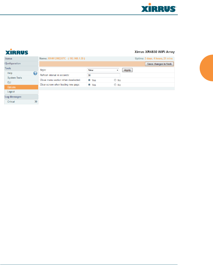
Wireless Array
Using Tools on the Wireless Array 373
Options
This window allows you to customize the behavior and appearance of the WMI.
By default, the Array uses the New style option, shown below.
Figure 181. WMI Display Options
Procedure for Configuring Options
1. Style: This option allows you to change the appearance and operation of
the user interface. Select one of the available styles from the drop-down
list. Click the Apply button to view the WMI with the selected style.
Note that some styles just change the display appearance (the skin) of
WMI, in much the same way as changing the display theme used in
Windows 7. Other styles include more extensive changes to the interface.
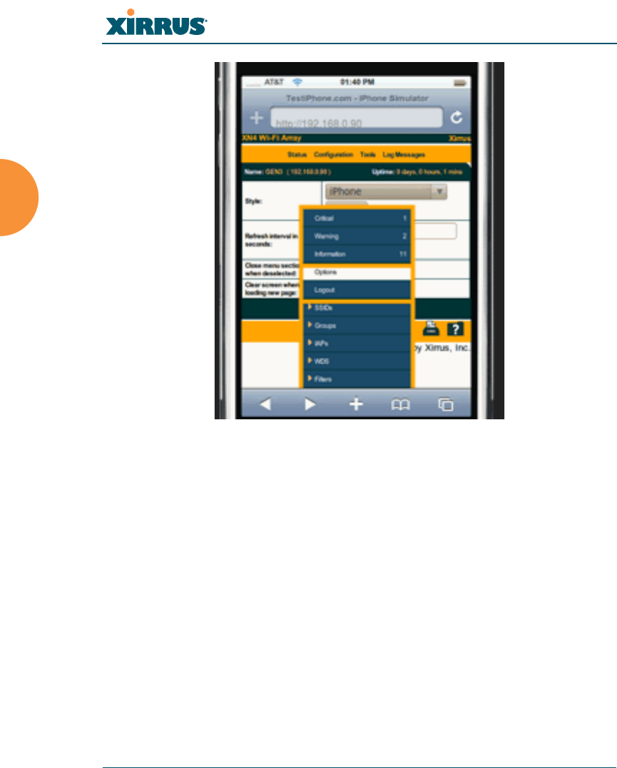
Wireless Array
374 Using Tools on the Wireless Array
Figure 182. iPhone Style Option
For example, the iPhone style option (Figure 182) has a more compact
display, suitable for use on smart phones. It shows the main menu in the
orange bar at the top, rather than as a tree in its own frame on the left.
Clicking one of the menu choices at the top in Figure 182 will display a
drop-down menu with the options for that menu choice. Menus may be
toggled on and off by clicking on the headers (Status, Configuration, etc.).
2. Refresh Interval in Seconds: Many of the windows in the Status section
of the WMI have an Auto Refresh option. You may use this setting to
change how often a status or statistics window is refreshed, if its auto
refresh option is enabled. Enter the desired number of seconds between
refreshes. The default refresh interval is 30 seconds.

Wireless Array
Using Tools on the Wireless Array 375
3. Close Menu Section when Deselected: When you click a main section
such as SSIDs in the left frame of the WMI (the navigation tree), the
section is expanded to show submenu choices. Click Yes to automatically
close any open submenus when you select a different section. If you click
No, all menu sections will remain expanded once opened. No is the
default. Note that if you enable this feature and you expand a section by
clicking its orange arrow, the section will stay open as you select
windows in other menu sections.
4. Clear Screen When Loading New Page: When this option is enabled and
you click on a page that takes a long time to load for any reason, the main
area of the screen is blanked out and displays a Loading… message. If
this option is disabled, WMI simply shows the page you were viewing
until the new page loads.
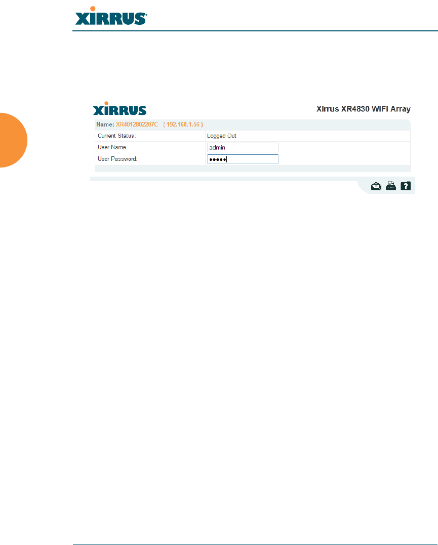
Wireless Array
376 Using Tools on the Wireless Array
Logout
Click on the Logout button to terminate your session. When the session is
terminated, you are presented with the Array’s login window.
Figure 183. Login Window