Cambium Networks XS3700A XS-3700 Wireless LAN Array User Manual xirrus array userguide2
Xirrus, Inc. XS-3700 Wireless LAN Array xirrus array userguide2
UserManual.wiki
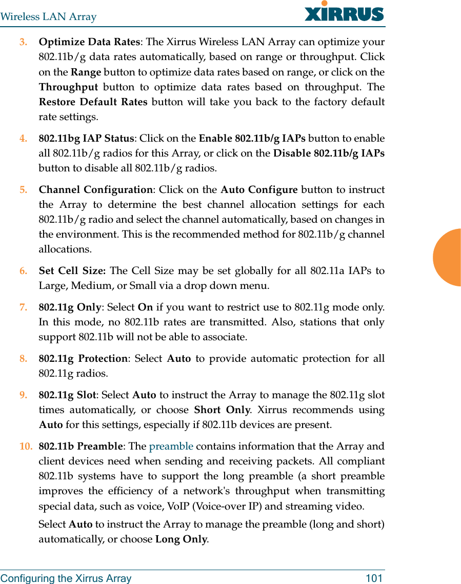
>
Cambium Networks
>
XS3700A User Manual
>
Users Manual Part 1
Contents
1.
Users Manual Part 1
2.
Users Manual Part 2
Users Manual Part 1
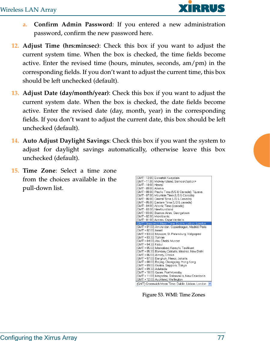
Navigation menu
Upload a User Manual
Namespaces
Wiki Guide
HTML
PDF
Info
Views
User Manual
Discussion / Help
Navigation
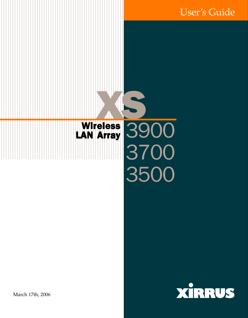
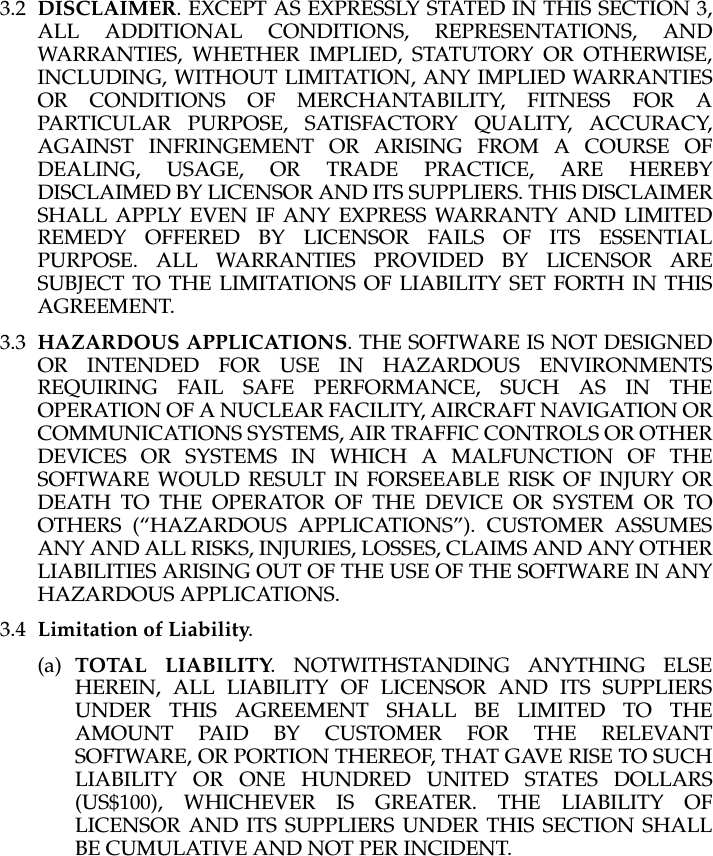
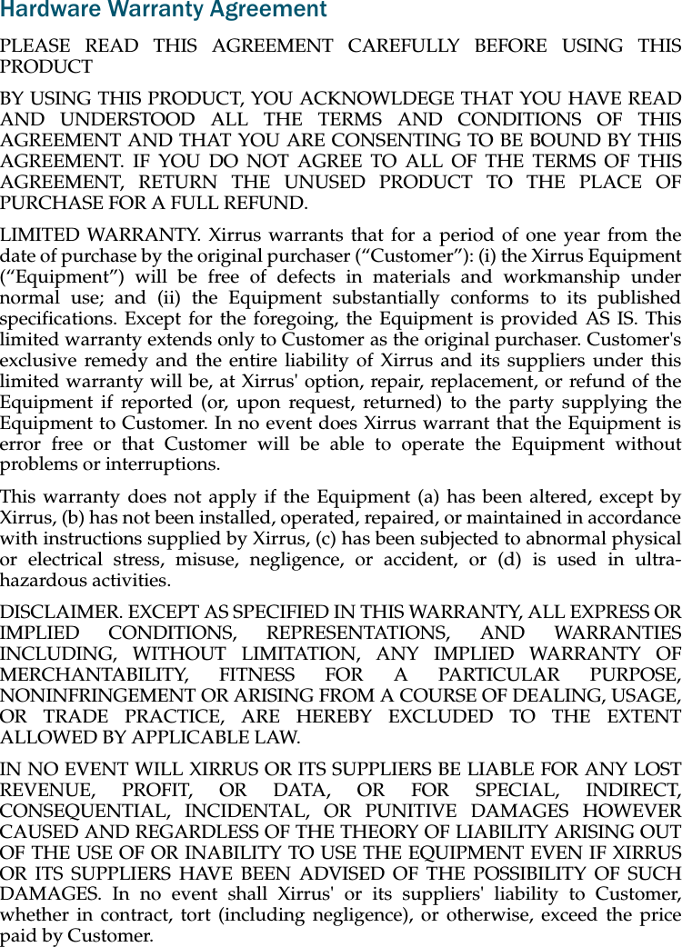
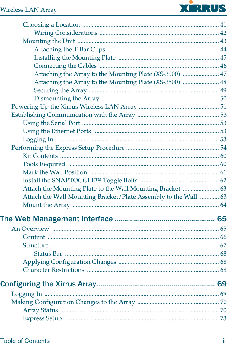
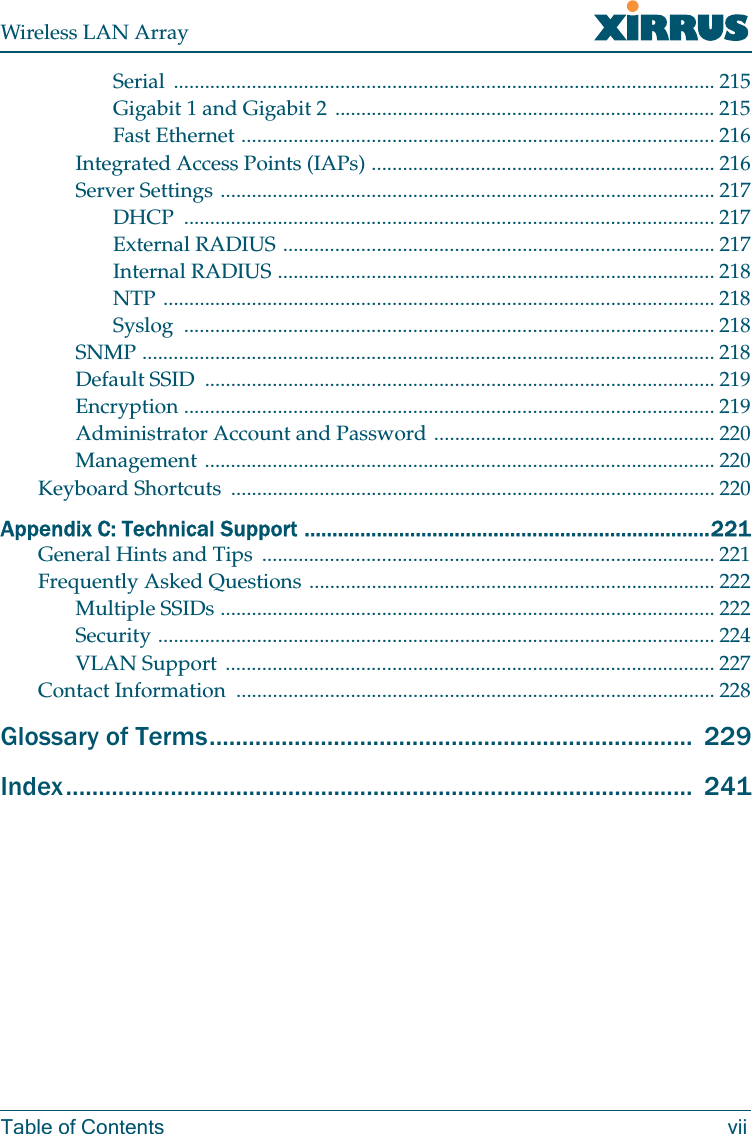
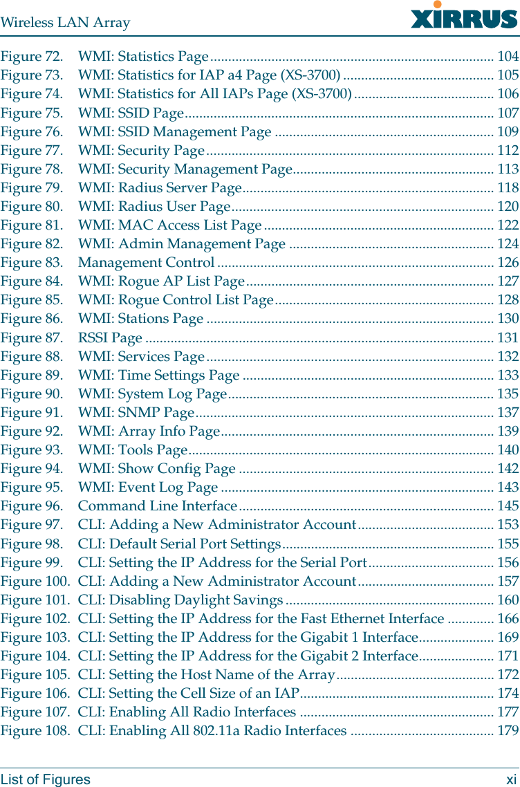
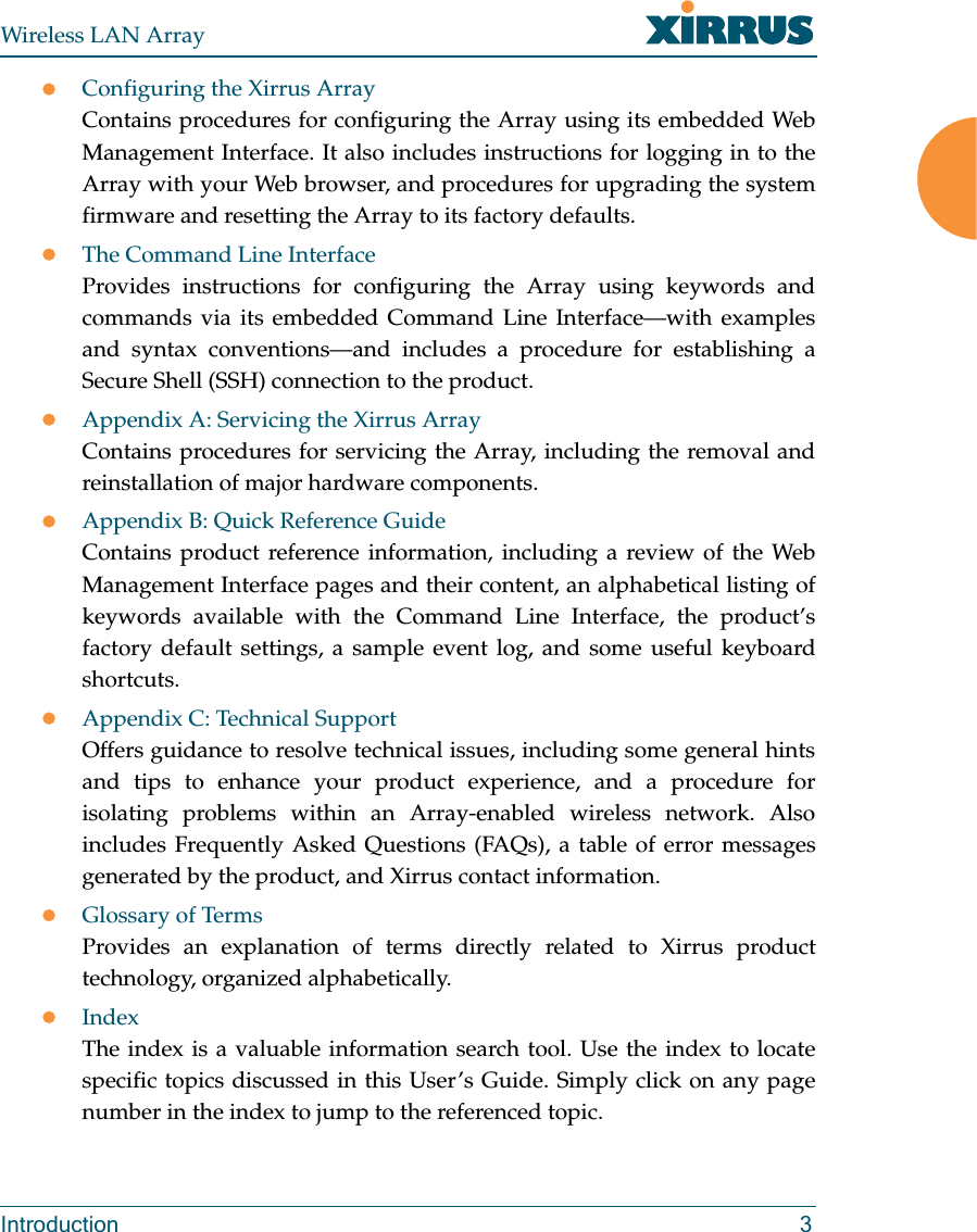
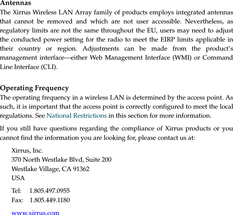
![EU Directive 1999/5/EC Compliance InformationThis section contains compliance information for the Xirrus Wireless LAN Arrayfamily of products, which includes the XS-3900, XS-3700 and XS-3500. Thecompliance information contained in this section is relevant to the EuropeanUnion and other countries that have implemented the EU Directive 1999/5/EC.Declaration of ConformityCesky [Czech] Toto zahzeni je v souladu se základnimi požadavky aostatnimi odpovidajcimi ustano veni mi SmČrnice1999/5/EC.Dansk [Danish] Dette udstyr er i overensstemmelse med devæsentlige krav og andre relevante bestemmelser iDirektiv 1999/5/EF.Deutsch [German] Dieses Gerat entspricht den grundlegendenAnforderungen und den weiteren entsprechendenVorgaben der Richtinie 1999/5/EU.Eesti [Estonian] See seande vastab direktiivi 1999/5/EU olulistelenöuetele ja teistele as jakohastele sätetele.English This equipment is in compliance with the essentialrequirements and other relevant provisions ofDirective 1999/5/EC.Español [Spain] Este equipo cump le con los requisitos esenciales asicomo con otras disposiciones de la Directiva 1999/5/CE.ǼȜȜȘȞȣțȘ [Greek] ǹȣIJȩȗ Ƞ İȟȠʌȜIJıµȩȗ İȓȞĮȚ ıİ ıȣµµȩȡijȦıȘ µİIJȚȗȠȣıȚȫįİȚȗ ĮʌĮȚIJȒıİȚȗ țĮȚ ȪȜȜİȗ ıȤİIJȚțȑȗ įȚĮIJȐȟİȚȗ IJȘȗȅįȘȖȚĮȗ 1999/5/EC.Français [French] Cet appareil est conforme aux exigences essentielleset aux autres dispositions pertinentes de la Directive1999/5/EC.Ďslenska [Icelandic] Þetta tæki er samkvæmt grunnkröfum og öðrumviðeigandi ákvæðum Tilskipunar 1999/5/EC.](https://usermanual.wiki/Cambium-Networks/XS3700A.Users-Manual-Part-1/User-Guide-649366-Page-5.png)
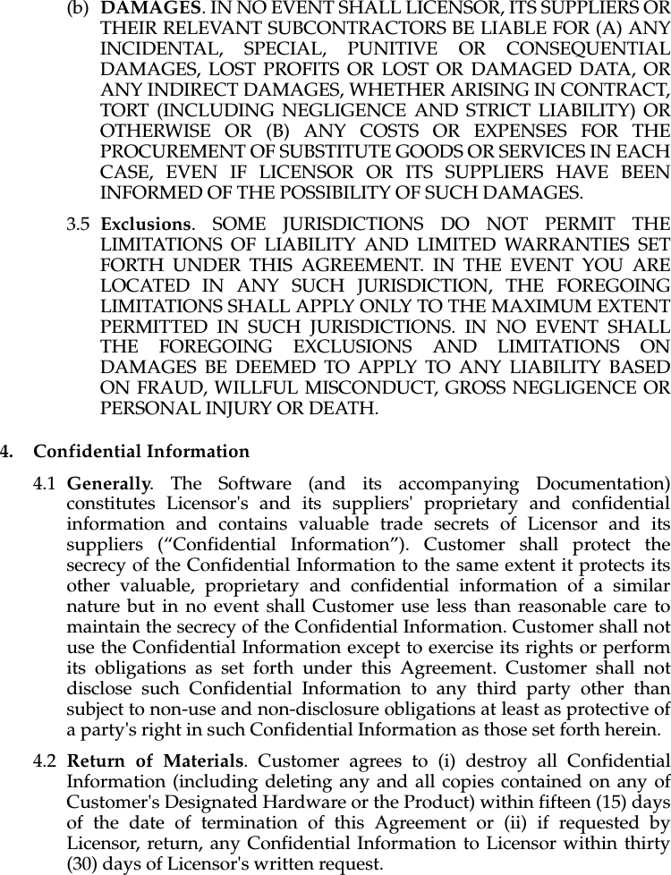
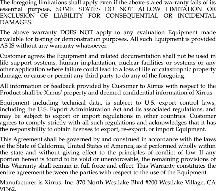
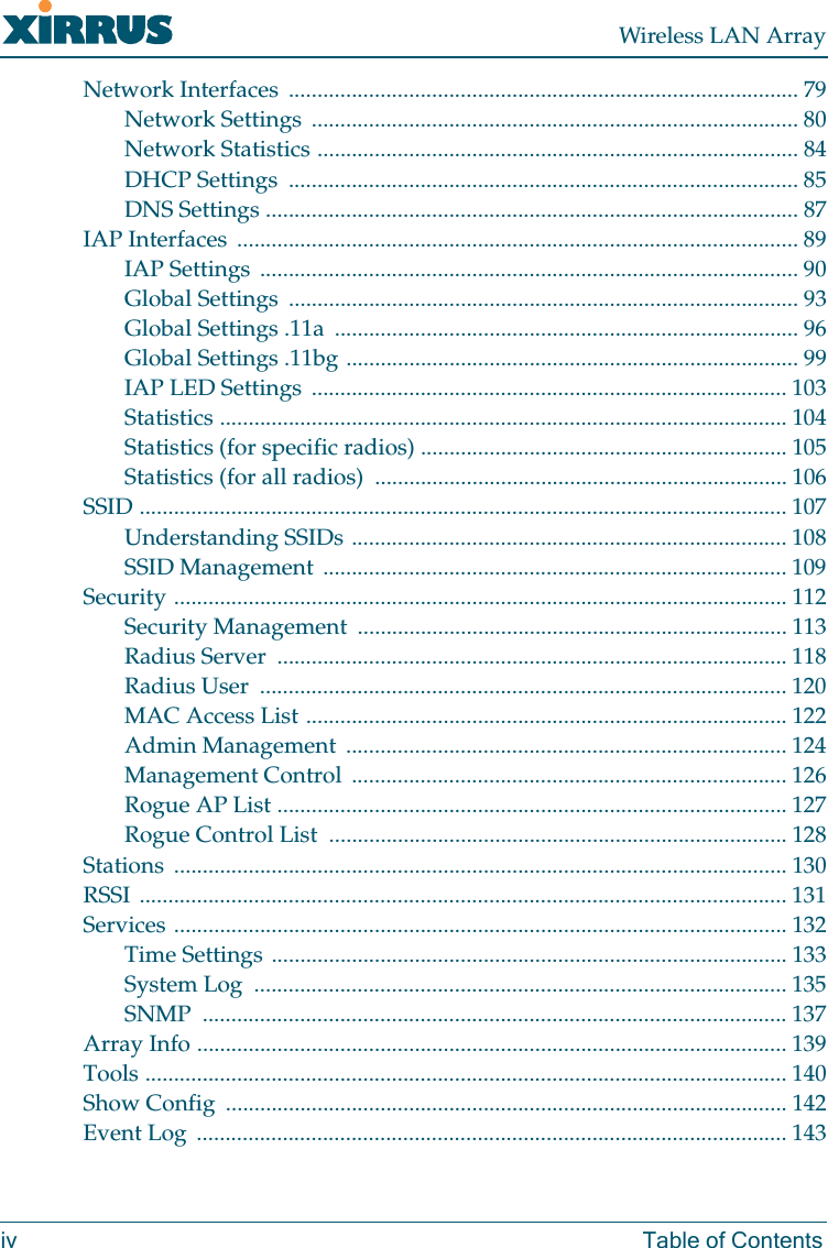
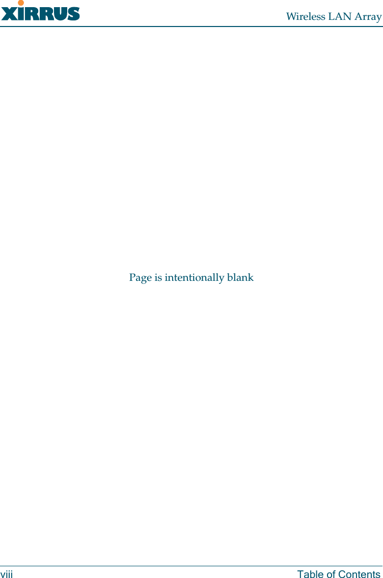
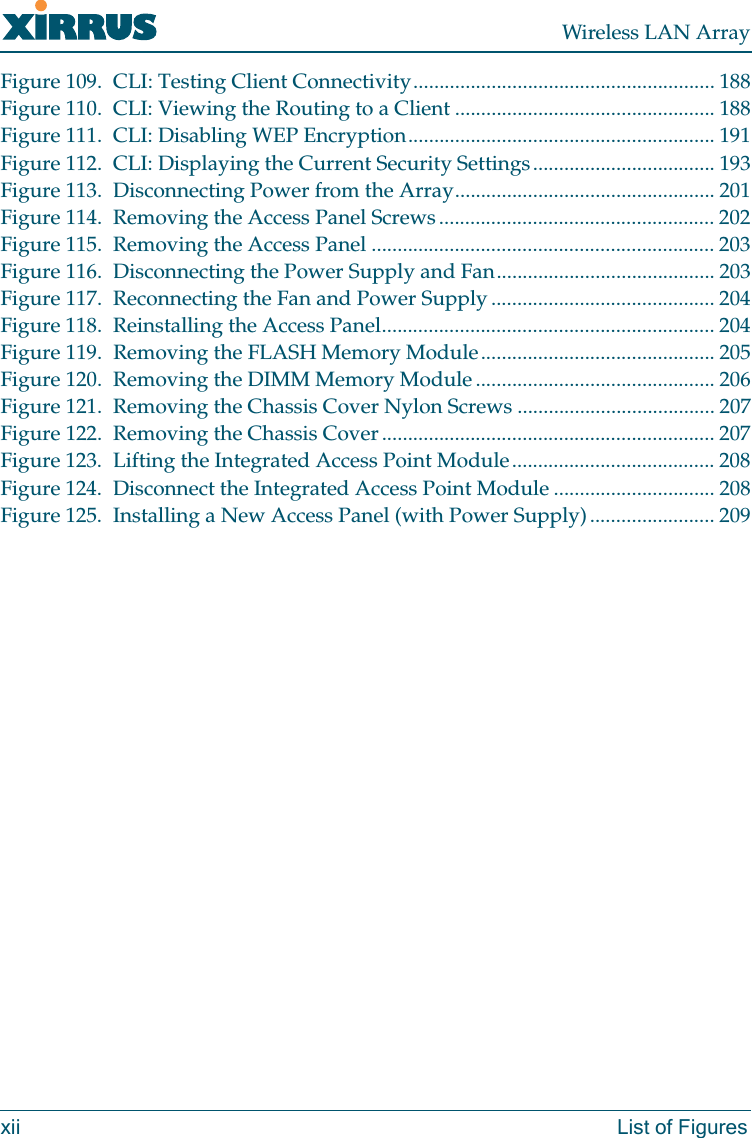
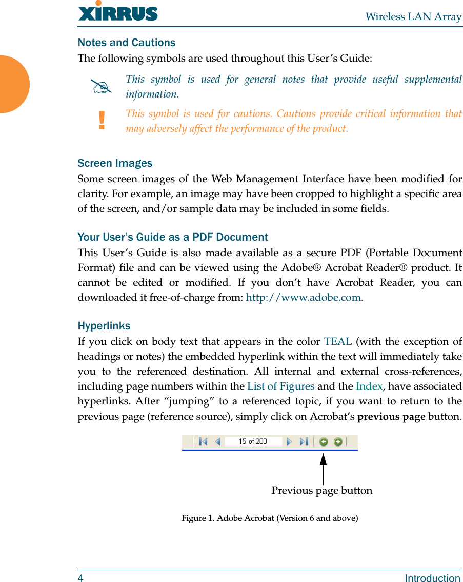
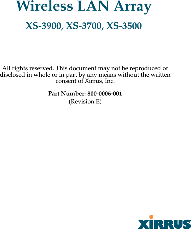
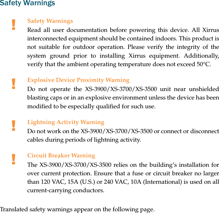
![Italiano [Italian] Questo apparato é conforme ai requisiti essenziali edagli altri principi sanciti dalla Direttiva 1999/5/CE.Latviski [Latvian] ŠƯiekƗrta atbilst DirektƯvas 1999/5/EK bnjtiskajƗprasƯbƗm un citiem ar to saistƯtajiem noteikumiem.Lietuviǐ [Lithuanian] Šis Ƴrenginys tenkina 1995/5/EB Direktyvosesminius reikalavimus ir kitas šios direktyvosnuostatas.Nederlands [Dutch] Dit apparant voldoet aan de essentiele eisen enandere van toepassing zijnde bepalingen van deRichtlijn 1995/5/EC.Malti [Maltese] Dan l-apparant huwa konformi mal-htigiet essenzjaliu l-provedimenti l-ohra rilevanti tad-Direttiva 1999/5/EC.Margyar [Hungarian] Ez a készülék teljesiti az alapvetö követelményeketés más 1999/5/EK irányelvben meghatározottvonatkozó rendelkezéseket.Norsk [Norwegian] Dette utstyret er i samsvar med de grunnleggendekrav og andre relevante bestemmelser i EU-direktiv1999/5/EF.Polski [Polish] Urządzenie jest zgodne z ogólnymi wymaganiamioraz sczególnymi mi warunkami okreĞlony miDyrektywą. UE:1999/5/EC.Portuguès [Portugese] Este equipamento está em conformidade com osrequisitos essenciais e outras provisões relevantes daDirectiva 1999/5/EC.Slovensko [Slovenian] Ta naprava je skladna z bistvenimi zahtevami inostalimi relevantnimi popoji Direktive 1999/5/EC.Slovensky [Slovak] Toto zariadenie je v zhode so základnýmipožadavkami a inými prislušnými nariadeniamidirektiv: 1999/5/EC.](https://usermanual.wiki/Cambium-Networks/XS3700A.Users-Manual-Part-1/User-Guide-649366-Page-6.png)
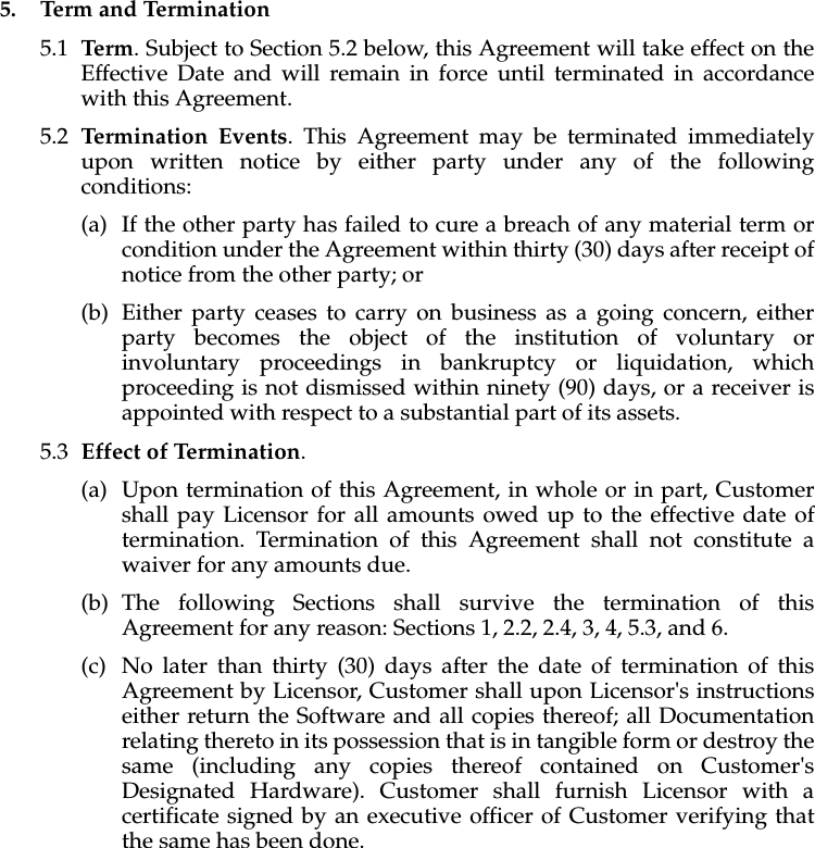
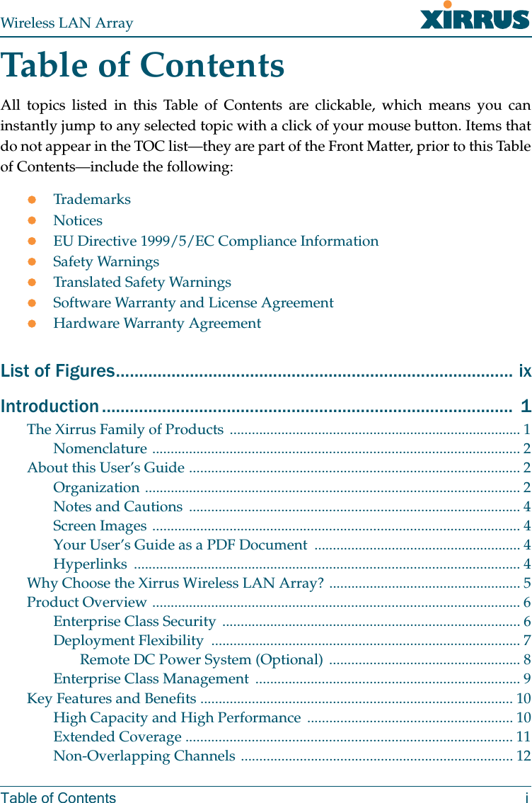
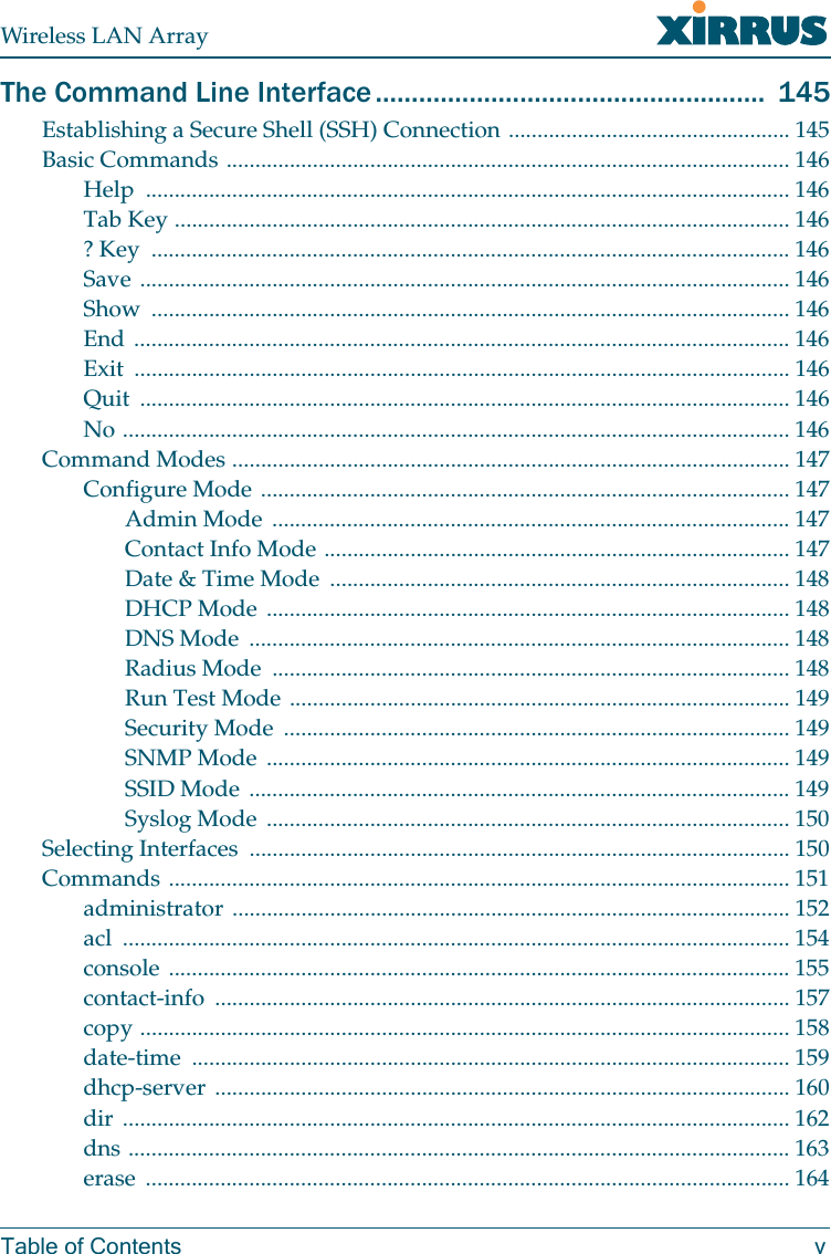
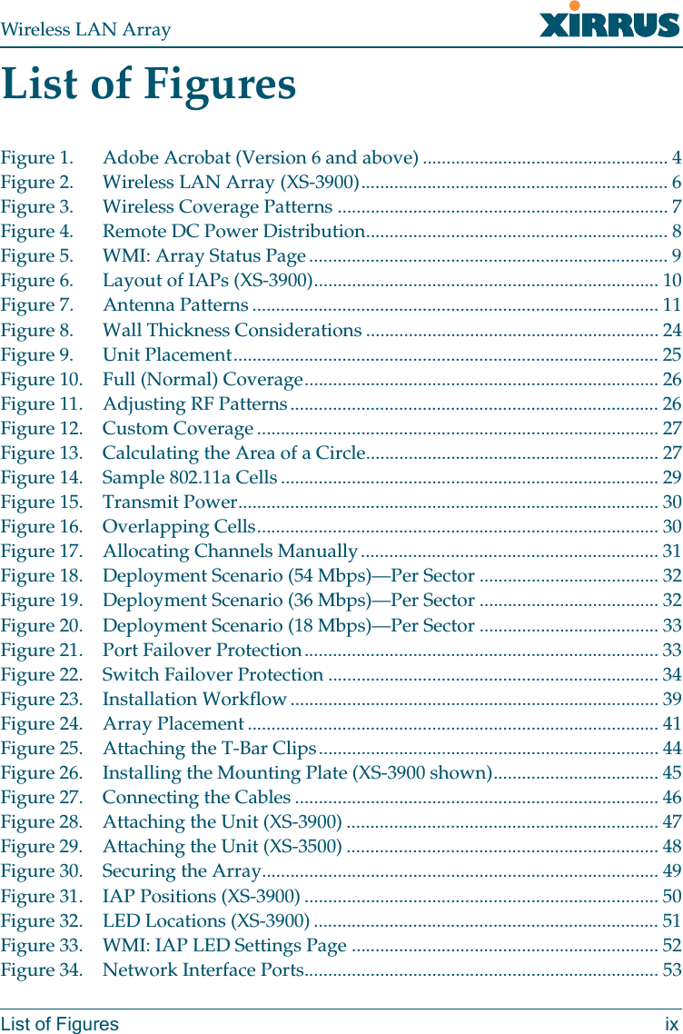
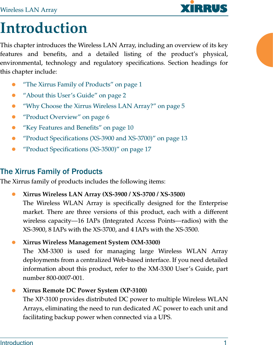
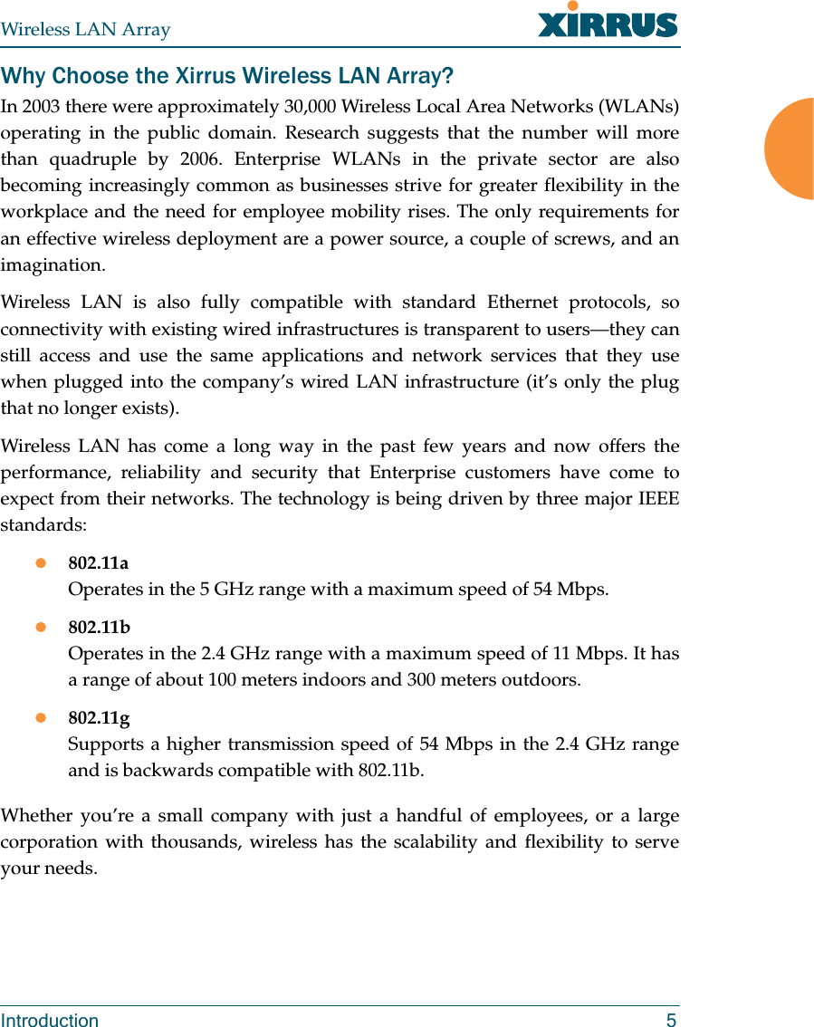
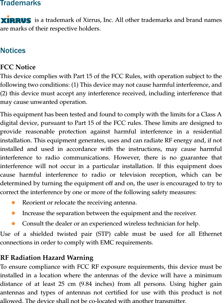
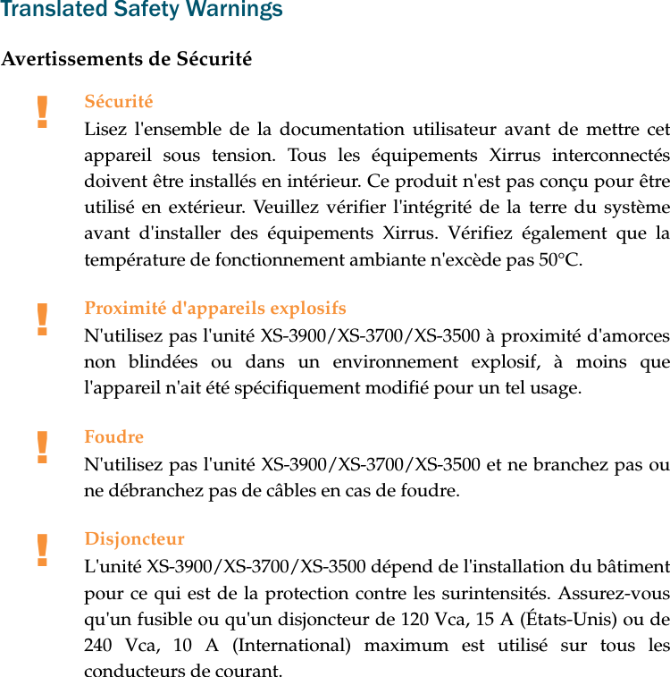
![Assessment CriteriaThe following standards were applied during the assessment of the productagainst the requirements of the Directive 1999/5/EC:zRadio: EN 301 893 and EN 300 328 (if applicable)zEMC: EN 301 489-1 AND en 301 489-17zSafety: EN 50371 to EN 50385CE MarkingFor the Xirrus Wireless LAN Array (XS-3900, XS-3700 and XS-3500), the CE markand Class-2 identifier opposite are affixed to the equipment and its packaging:Suomi [Finnish] Tämä laite täyttää direktiivin 1999/5//EY olennaisetvaatimukset ja on siinä asetettujen muiden laitettakoskevien määräysten mukainen.Svenska [Swedish] Denna utrustning är i överensstämmelse med deväsentliga kraven och andra relevanta bestämmelseri Direktiv 1999/5/EC.](https://usermanual.wiki/Cambium-Networks/XS3700A.Users-Manual-Part-1/User-Guide-649366-Page-7.png)
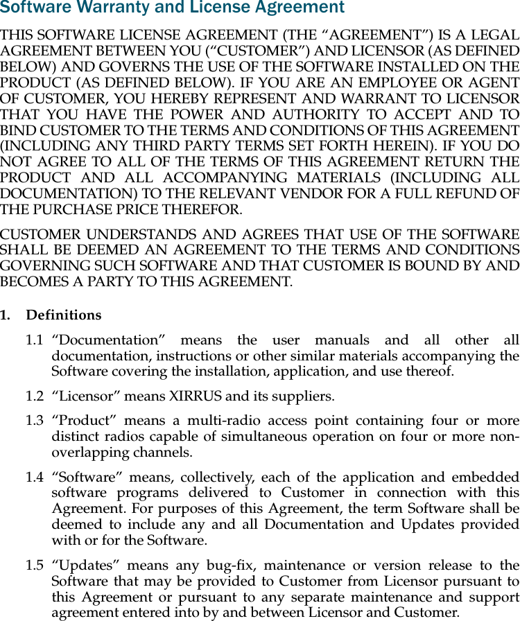
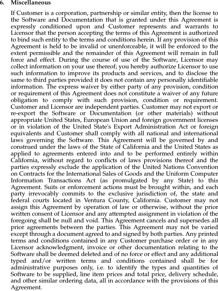
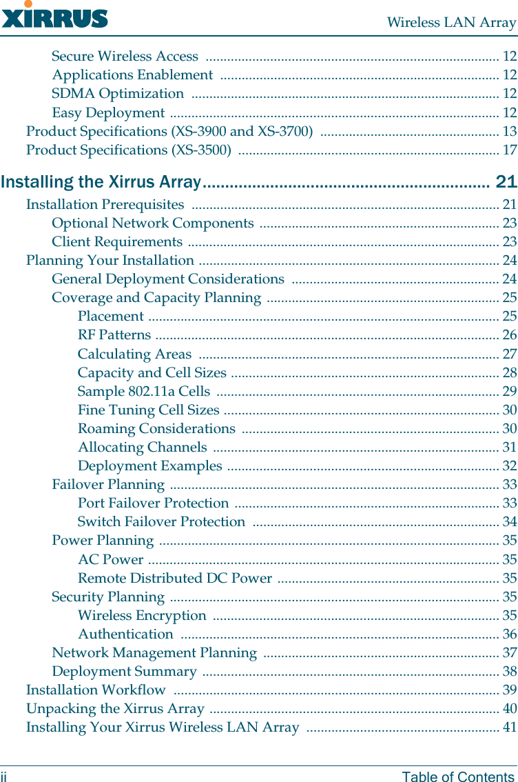
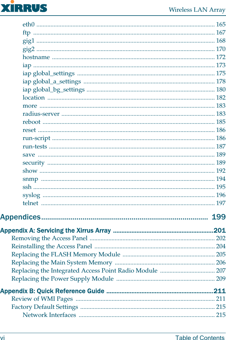
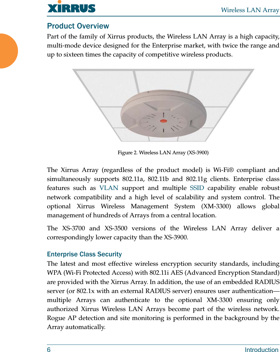
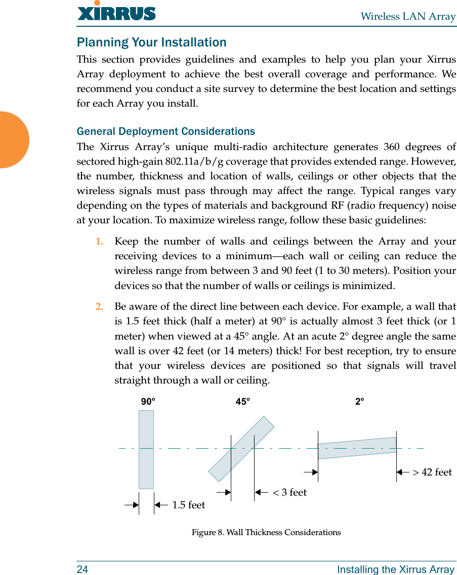
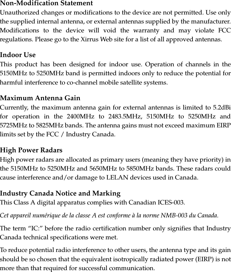
![2.4 Restrictions. Customer shall not itself, or through any parent, subsidiary,affiliate, agent or other third party (i) sell, rent, lease, license orsublicense, assign or otherwise transfer the Software, or any ofCustomer's rights and obligations under this Agreement except asexpressly permitted herein; (ii) decompile, disassemble, or reverseengineer the Software, in whole or in part, provided that in thosejurisdictions in which a total prohibition on any reverse engineering isprohibited as a matter of law and such prohibition is not cured by the factthat this Agreement is subject to the laws of the State of California,Licensor agrees to grant Customer, upon Customer's written request toLicensor, a limited reverse engineering license to permit interoperabilityof the Software with other software or code used by Customer; (iii) allowaccess to the Software by any user other than by Customer's employeesand contractors who are bound in writing to confidentiality and non-userestrictions at least as protective as those set forth herein; (iv) except asexpressly set forth herein, write or develop any derivative software orany other software program based upon the Software; or (v) use anycomputer software or hardware which is designated to defeat any copyprotection or other use limiting device, including any device intended tolimit the number of users or devices accessing the Product. 3. Limited Warranty and Limitation of Liability3.1 Limited Warranty & Exclusions. Licensor warrants that the Software willperform in substantial accordance with the specifications therefor setforth in the Documentation for a period of ninety [90] days afterCustomer's acceptance of the terms of this Agreement with respect to theSoftware (“Warranty Period”). If during the Warranty Period theSoftware does not perform as warranted, Licensor shall, at its option,correct the relevant Software giving rise to such breach of performance orreplace such Software free of charge. THE FOREGOING ARECUSTOMER'S SOLE AND EXCLUSIVE REMEDIES FOR BREACH OFTHE FOREGOING WARRANTY. THE WARRANTY SET FORTHABOVE IS MADE TO AND FOR THE BENEFIT OF CUSTOMER ONLY.The warranty will apply only if (i) the Software has been used at all timesand in accordance with the instructions for use set forth in theDocumentation and this Agreement; (ii) no modification, alteration oraddition has been made to the Software by persons other than Licensor orLicensor's authorized representative; and (iii) the Software or Product onwhich the Software is installed has not been subject to any unusualelectrical charge.](https://usermanual.wiki/Cambium-Networks/XS3700A.Users-Manual-Part-1/User-Guide-649366-Page-17.png)