Cameo Communications USR5453 Professional Access Point User Manual Instant802 APSDK Getting Started Guide
Cameo Communications Inc Professional Access Point Instant802 APSDK Getting Started Guide
Contents
- 1. Manual 1
- 2. Manual 2
Manual 1
Professional Access Point
Administrator Guide
R46.1161.00
rev 1.3 1/06

Professional Access Point
Administrator Guide
iii
Professional Access Point
Administrator Guide
U.S. Robotics Corporation
935 National Parkway
Schaumburg, Illinois
60173-5157
USA
No part of this documentation may be reproduced in any form or by any means or used to make any derivative work (such as a
translation, transformation, or adaptation) without written permission from U.S. Robotics Corporation. U.S. Robotics Corporation
reserves the right to revise this documentation and to make changes in the products and/or content of this document from time to
time without obligation to provide notification of such revision or change. U.S. Robotics Corporation provides this documentation
without warranty of any kind, either implied or expressed, including, but not limited to, implied warranties of merchantability and fit-
ness for a particular purpose. If there is any software on removable media described in this documentation, it is furnished under a
license agreement included with the product as a separate document, in the hard copy documentation, or on the removable media
in a directory named LICENSE. If you are unable to locate a copy, please contact USRobotics and a copy will be provided to you.
UNITED STATES GOVERNMENT LEGEND If you are a United States government agency, then this documentation and the soft-
ware described herein are provided to you subject to the following:
All technical data and computer software are commercial in nature and developed solely at private expense. Software is delivered
as “Commercial Computer Software” as defined in DFARS 252.227-7014 (June 1995) or as a “commercial item” as defined in
FAR 2.101(a) and as such is provided with only such rights as are provided in USRobotics standard commercial license for the
Software. Technical data is provided with limited rights only as provided in DFAR 252.227-7015 (Nov 1995) or FAR 52.227-14
(June 1987) whichever is applicable. You agree not to remove or deface any portion of any legend provided on any licensed pro-
gram or documentation contained in, or delivered to you in conjunction with, this Administrator Guide.
Copyright © 2005 U.S. Robotics Corporation. All rights reserved. U.S. Robotics and the USRobotics logo are registered trade-
marks of U.S. Robotics Corporation. Other product names are for identification purposes only and may be trademarks of their
respective companies. Product specifications subject to change without notice.

Professional Access Point
Administrator Guide
iv

Professional Access Point
Administrator Guide
v
Contents
About This Document . . . . . . . . . . . . . . . . . . . . . . . . . . . . . . . . . . . . .ix
Getting Started
Overview . . . . . . . . . . . . . . . . . . . . . . . . . . . . . . . . . . . . . . . . . . . . . . 1
Features and Benefits . . . . . . . . . . . . . . . . . . . . . . . . . . . . . . . . . . . . . . . . . . . . . . . . . . . . . 2
What’s Next? . . . . . . . . . . . . . . . . . . . . . . . . . . . . . . . . . . . . . . . . . . . . . . . . . . . . . . . . . . . 4
Pre-Launch Checklist: Default Settings and Supported Administrator/
Client Platforms . . . . . . . . . . . . . . . . . . . . . . . . . . . . . . . . . . . . . . . . . 5
Professional Access Point . . . . . . . . . . . . . . . . . . . . . . . . . . . . . . . . . . . . . . . . . . . . . . . . . . . 5
Administrator’s Computer . . . . . . . . . . . . . . . . . . . . . . . . . . . . . . . . . . . . . . . . . . . . . . . . . . 8
Wireless Client Computers . . . . . . . . . . . . . . . . . . . . . . . . . . . . . . . . . . . . . . . . . . . . . . . . . . 9
Understanding Dynamic and Static IP Addressing on the Professional Access Point . . . . . . . . . . 10
Setting Up and Launching Your Wireless Network. . . . . . . . . . . . . . 13
Step 1. Unpack the access point . . . . . . . . . . . . . . . . . . . . . . . . . . . . . . . . . . . . . . . . . . . . . 13
Step 2. Connect the access point to network and power . . . . . . . . . . . . . . . . . . . . . . . . . . . . 14
Step 3. Run the Detection Utility to find access points on the network. . . . . . . . . . . . . . . . . . . 16
Step 4. Log on to the Web User Interface . . . . . . . . . . . . . . . . . . . . . . . . . . . . . . . . . . . . . . 19
Step 5. Configure Basic Settings and start the wireless network . . . . . . . . . . . . . . . . . . . . . . . 21
Wall Mounting the Access Point. . . . . . . . . . . . . . . . . . . . . . . . . . . . . . . . . . . . . . . . . . . . . . 23
What’s Next? . . . . . . . . . . . . . . . . . . . . . . . . . . . . . . . . . . . . . . . . . . . . . . . . . . . . . . . . . . 23
Web User Interface
Basic Settings . . . . . . . . . . . . . . . . . . . . . . . . . . . . . . . . . . . . . . . . . . 25
Navigating to Basic Settings . . . . . . . . . . . . . . . . . . . . . . . . . . . . . . . . . . . . . . . . . . . . . . . . 26
Review / Describe the Access Point . . . . . . . . . . . . . . . . . . . . . . . . . . . . . . . . . . . . . . . . . . . 27
Provide Administrator Password and Wireless Network Name . . . . . . . . . . . . . . . . . . . . . . . . . 28
Set Configuration Policy for New Access Points . . . . . . . . . . . . . . . . . . . . . . . . . . . . . . . . . . . 29
Update Basic Settings . . . . . . . . . . . . . . . . . . . . . . . . . . . . . . . . . . . . . . . . . . . . . . . . . . . . 30
Summary of Settings. . . . . . . . . . . . . . . . . . . . . . . . . . . . . . . . . . . . . . . . . . . . . . . . . . . . . 30
Basic Settings for a Standalone Access Point . . . . . . . . . . . . . . . . . . . . . . . . . . . . . . . . . . . . 31
Your Network at a Glance: Understanding Indicator Icons . . . . . . . . . . . . . . . . . . . . . . . . . . . 31
Cluster . . . . . . . . . . . . . . . . . . . . . . . . . . . . . . . . . . . . . . . . . . . . . . . 33
Access Points . . . . . . . . . . . . . . . . . . . . . . . . . . . . . . . . . . . . . . . . . . . . . . . . . . . . . . . . . . 33
User Management . . . . . . . . . . . . . . . . . . . . . . . . . . . . . . . . . . . . . . . . . . . . . . . . . . . . . . . 43
Sessions . . . . . . . . . . . . . . . . . . . . . . . . . . . . . . . . . . . . . . . . . . . . . . . . . . . . . . . . . . . . . 49
Channel Management . . . . . . . . . . . . . . . . . . . . . . . . . . . . . . . . . . . . . . . . . . . . . . . . . . . . 53
Wireless Neighborhood . . . . . . . . . . . . . . . . . . . . . . . . . . . . . . . . . . . . . . . . . . . . . . . . . . . 61
Status . . . . . . . . . . . . . . . . . . . . . . . . . . . . . . . . . . . . . . . . . . . . . . . . 67
Interfaces . . . . . . . . . . . . . . . . . . . . . . . . . . . . . . . . . . . . . . . . . . . . . . . . . . . . . . . . . . . . 67

Professional Access Point
Administrator Guide
vi
Events . . . . . . . . . . . . . . . . . . . . . . . . . . . . . . . . . . . . . . . . . . . . . . . . . . . . . . . . . . . . . . . 69
Transmit/Receive Statistics . . . . . . . . . . . . . . . . . . . . . . . . . . . . . . . . . . . . . . . . . . . . . . . . 72
Client Associations . . . . . . . . . . . . . . . . . . . . . . . . . . . . . . . . . . . . . . . . . . . . . . . . . . . . . . 73
Neighboring Access Points . . . . . . . . . . . . . . . . . . . . . . . . . . . . . . . . . . . . . . . . . . . . . . . . . 75
Advanced . . . . . . . . . . . . . . . . . . . . . . . . . . . . . . . . . . . . . . . . . . . . . 79
Ethernet (Wired) Settings . . . . . . . . . . . . . . . . . . . . . . . . . . . . . . . . . . . . . . . . . . . . . . . . . 79
Wireless Settings . . . . . . . . . . . . . . . . . . . . . . . . . . . . . . . . . . . . . . . . . . . . . . . . . . . . . . . 87
Security . . . . . . . . . . . . . . . . . . . . . . . . . . . . . . . . . . . . . . . . . . . . . . . . . . . . . . . . . . . . . . 91
Guest Login . . . . . . . . . . . . . . . . . . . . . . . . . . . . . . . . . . . . . . . . . . . . . . . . . . . . . . . . . . 111
Virtual Wireless Networks. . . . . . . . . . . . . . . . . . . . . . . . . . . . . . . . . . . . . . . . . . . . . . . . . 115
Radio. . . . . . . . . . . . . . . . . . . . . . . . . . . . . . . . . . . . . . . . . . . . . . . . . . . . . . . . . . . . . . . 119
MAC Filtering . . . . . . . . . . . . . . . . . . . . . . . . . . . . . . . . . . . . . . . . . . . . . . . . . . . . . . . . . 125
Load Balancing . . . . . . . . . . . . . . . . . . . . . . . . . . . . . . . . . . . . . . . . . . . . . . . . . . . . . . . . 129
Quality of Service . . . . . . . . . . . . . . . . . . . . . . . . . . . . . . . . . . . . . . . . . . . . . . . . . . . . . . 133
Wireless Distribution System . . . . . . . . . . . . . . . . . . . . . . . . . . . . . . . . . . . . . . . . . . . . . . 143
Time Protocol . . . . . . . . . . . . . . . . . . . . . . . . . . . . . . . . . . . . . . . . . . . . . . . . . . . . . . . . . 151
SNMP . . . . . . . . . . . . . . . . . . . . . . . . . . . . . . . . . . . . . . . . . . . . . . . . . . . . . . . . . . . . . . 155
Reboot. . . . . . . . . . . . . . . . . . . . . . . . . . . . . . . . . . . . . . . . . . . . . . . . . . . . . . . . . . . . . . 159
Reset Configuration. . . . . . . . . . . . . . . . . . . . . . . . . . . . . . . . . . . . . . . . . . . . . . . . . . . . . 159
Upgrade. . . . . . . . . . . . . . . . . . . . . . . . . . . . . . . . . . . . . . . . . . . . . . . . . . . . . . . . . . . . . 160
Backup/Restore . . . . . . . . . . . . . . . . . . . . . . . . . . . . . . . . . . . . . . . . . . . . . . . . . . . . . . . 162
Command Line Interface
Class Structure, Commands, and Examples . . . . . . . . . . . . . . . . . . 165
Comparison of Settings Configurable with the CLI and Web User Interface. . . . . . . . . . . . . . . 166
How to Access the CLI for an Access Point . . . . . . . . . . . . . . . . . . . . . . . . . . . . . . . . . . . . . 169
Quick View of Commands and How to Get Help. . . . . . . . . . . . . . . . . . . . . . . . . . . . . . . . . . 171
Command Usage and Configuration Examples . . . . . . . . . . . . . . . . . . . . . . . . . . . . . . . . . . 175
Keyboard Shortcuts and Tab Completion Help . . . . . . . . . . . . . . . . . . . . . . . . . . . . . . . . . . 233
CLI Class and Field Overview . . . . . . . . . . . . . . . . . . . . . . . . . . . . . . . . . . . . . . . . . . . . . . 236
Class and Field Reference. . . . . . . . . . . . . . . . . . . . . . . . . . . . . . . . 239
Troubleshooting
Installation and Connectivity Troubleshooting . . . . . . . . . . . . . . . 269
Configuration Troubleshooting. . . . . . . . . . . . . . . . . . . . . . . . . . . . 273
Wireless Distribution System (WDS) Problems and Solutions . . . . . . . . . . . . . . . . . . . . . . . . 273
Cluster Recovery. . . . . . . . . . . . . . . . . . . . . . . . . . . . . . . . . . . . . . . . . . . . . . . . . . . . . . . 274
Support Information . . . . . . . . . . . . . . . . . . . . . . . . . . . . . . . . . . . 277
Regulatory Information . . . . . . . . . . . . . . . . . . . . . . . . . 279
Manufacturer’s Declaration of Conformity. . . . . . . . . . . . . . . . . . . . . . . . . . . . . . . . . . . . . . 279
For Canadian Users . . . . . . . . . . . . . . . . . . . . . . . . . . . . . . . . . . . . . . . . . . . . . . . . . . . . . 280

Professional Access Point
Administrator Guide
vii
CE Compliance . . . . . . . . . . . . . . . . . . . . . . . . . . . . . . . . . . . . . . . . . . . . . . . . . . . . . . . . 281
U.S. Robotics Corporation Two (2) Year Limited Warranty .
283
1.0 GENERAL TERMS: . . . . . . . . . . . . . . . . . . . . . . . . . . . . . . . . . . . . . . . . . . . . . . . . . . . 283
2.0 CUSTOMER OBLIGATIONS:. . . . . . . . . . . . . . . . . . . . . . . . . . . . . . . . . . . . . . . . . . . . . 283
3.0 OBTAINING WARRANTY SERVICE: . . . . . . . . . . . . . . . . . . . . . . . . . . . . . . . . . . . . . . . . 284
4.0 WARRANTY REPLACEMENT: . . . . . . . . . . . . . . . . . . . . . . . . . . . . . . . . . . . . . . . . . . . . 284
5.0 LIMITATIONS:. . . . . . . . . . . . . . . . . . . . . . . . . . . . . . . . . . . . . . . . . . . . . . . . . . . . . . 285
6.0 DISCLAIMER: . . . . . . . . . . . . . . . . . . . . . . . . . . . . . . . . . . . . . . . . . . . . . . . . . . . . . . 286
7.0 GOVERNING LAW: . . . . . . . . . . . . . . . . . . . . . . . . . . . . . . . . . . . . . . . . . . . . . . . . . . . 286
Glossary . . . . . . . . . . . . . . . . . . . . . . . . . . . . . . . . . . . . . 287
Index. . . . . . . . . . . . . . . . . . . . . . . . . . . . . . . . . . . . . . . . 307

Professional Access Point
Administrator Guide
viii
Professional Access Point
Administrator Guide
ix
About This Document
This guide describes setup, configuration, administration and maintenance of one or more Professional
Access Points on a wireless network.
Administrator Audience
This information is intended for the person responsible for installing, configuring, monitoring, and
maintaining the Professional Access Point as part of a small-to-medium business information technology
infrastructure.
Online Help Features
Online Help for the Professional Access Point Web User Interface provides information about all fields and
features available in the interface. The information in the Online Help is a subset of the information
available in the Administrator Guide.
Online Help information corresponds to each tab on the Professional Access Point Web User Interface. To
display help for the current tab, Click Help at the top of the Web User Interface page or click the More... link
at the bottom of the tab’s inline help panel.

Professional Access Point
Administrator Guide
x
Recommended Settings, Notes and Cautions
An arrow next to field description information indicates a recommended or suggested configuration
setting for an option on the Access Point.
A Note provides more information about a feature or technology and cross-references to related topics.
Typographical Conventions
This guide uses the following typographical conventions:
PDF Links
In addition to URL links, which are shown in blue and underscored, this document contains links to
related sections and to glossary terms. Whenever your cursor turns into the pointing hand, a single
click will take you to the referenced topic.
A Caution provides information about critical aspects of access point configuration, combinations of set-
tings, events, or procedures that can adversely affect network connectivity, security, and so on.
italics Glossary terms, new terms, and book titles
typewriter font
Screen text, URLs, IP addresses, and MAC addresses, UNIX file, command, and
directory names, user-typed command-line entries
typewriter font italics
Variables
Bold Keywords Menu titles, window names, and button names

Professional Access Point
Administrator Guide
Overview - 1
Getting Started
This part of the Professional Access Point Administrator Guide provides the information that you need to
establish a network by performing basic installation for one or more Professional Access Points:
•Overview
•Pre-Launch Checklist: Default Settings and Supported Administrator/Client Platforms
•Setting Up and Launching Your Wireless Network
Overview
The Professional Access Point provides continuous, high-speed access between your wireless and
Ethernet devices. It is an advanced, standards-based solution for wireless networking in small and
medium-sized businesses. The Professional Access Point enables zero-administration wireless local area
network (WLAN) deployment while providing state-of-the-art wireless networking features.
The Professional Access Point provides best-of-breed security, ease-of-administration, and industry
standards—providing a standalone and fully-secured wireless network without the need for additional
management and security server software.
The access point can broadcast in the following modes.
• IEEE 802.11b
• IEEE 802.11g
The following sections list features and benefits of the Professional Access Point, and tell you what’s next
when you’re ready to get started.
•Features and Benefits
•IEEE Standards Support and Wi-Fi Compliance
•Wireless Features
•Security Features
•Guest Interface
•Clustering and Auto-Management
•Networking

Professional Access Point
Administrator Guide
Overview - 2
•Maintainability
•What’s Next?
Features and Benefits
IEEE Standards Support and Wi-Fi Compliance
• Support for IEEE 802.11b and IEEE 802.11g wireless networking standards
• Provides bandwidth of up to 11 Mbps for IEEE 802.11b and 54 Mbps for IEEE 802.11g
• Wi-Fi compliance required for certification
Wireless Features
• Auto channel selection at startup
• Transmit power adjustment
• Wireless Distribution System (WDS) for connecting multiple access points wirelessly. Extends your
network with less cabling and provides a seamless experience for roaming clients.
• Quality of Service (QoS) for enhanced throughput and better performance of time-sensitive wireless
traffic like Video, Audio, Voice over IP (VoIP) and streaming media. The Professional Access Point
QoS is Wi-Fi Multimedia (WMM) compliant.
• Load Balancing
• Built-in support for multiple SSIDs (network names) and multiple BSSIDs (basic service set IDs) on the
same access point
• Channel management for automatic coordination of radio channel assignments to reduce access-
point-to-access-point interference on the network and maximise Wi-Fi bandwidth
• Neighbouring access point detection finds nearby access points, including rogues.
• Support for multiple IEEE 802.11d Regulatory Domains (country codes for global operation)
Security Features
• Prohibit SSID Broadcast
• Station isolation
• Weak IV avoidance
• Wireless Equivalent Privacy (WEP)

Professional Access Point
Administrator Guide
Overview - 3
• Wi-Fi Protected Access 2 (WPA2/802.11i)
• Advanced Encryption Standard (AES)
• User-based access control, local user database, and user life-cycle management with built-in RADIUS
authentication server
• WPA/WPA2 Enterprise
• MAC address filtering
Guest Interface
• Unique network name (SSID) for the Guest interface
• Captive portal to guide guests to customized, guest-only Web page
• VLAN implementation
Clustering and Auto-Management
• Automatic setup with the Professional Access Point Detection Utility
• Provisioning and auto-configuration of access points through clustering and cluster rendezvous
The administrator can specify how new access points should be configured before they are added to
the network. When new access points are added to the same wired network, they can automatically
rendezvous with the cluster and securely download the correct configuration. The process does not
require manual intervention, but is under the control of the administrator.
• Single universal view of clustered access points and cluster configuration settings
Configuration for all access points in a cluster can be managed from a single interface. Changes to
common parameters are automatically reflected in all members of the cluster.
• Self-managed access points with automatic configuration synchronization
The access points in a cluster periodically ensure that the cluster configuration is consistent, and
check for the presence and availability of the other members of the cluster. The administrator can mon-
itor this information through the Web User Interface.
• Enhanced local authentication using 802.1x without additional IT setup
A cluster can maintain a user authentication server and database stored on the access points. This
eliminates the need to install, configure, and maintain a RADIUS infrastructure and simplifies the
administrative task of deploying a secure wireless network.
Networking
• Dynamic Host Configuration Protocol (DHCP) support for dynamically assigning network configuration

Professional Access Point
Administrator Guide
Overview - 4
information to systems on the LAN/WLAN.
• Virtual Local Area Network (VLAN) support
SNMP Support
The Professional Access Point includes the following standard Simple Network Protocol (SNMP)
Management Information Bases (MIB):
• SNMP v1 and v2 MIBs
• IEEE802.11 MIB
• Four USRobotics proprietary MIBs support product, system, channel, and wireless system statistics.
Maintainability
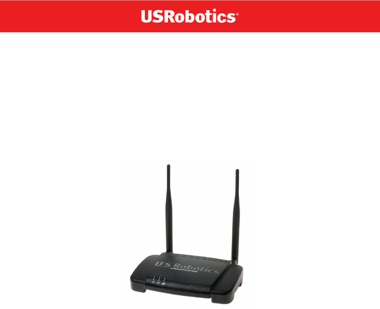
• Status, monitoring, and tracking views of the network including session monitoring, client associations,
transmit/receive statistics, and event log
• Link integrity monitoring to continually verify connection to the client, regardless of network traffic
activity levels
• Reset configuration option
• Firmware upgrade
• Backup and restore of access point configuration
• Backup and restore of user database for built-in RADIUS server (when using IEEE 802.1x or WPA/
WPA2 Enterprise (RADIUS) security mode)
What’s Next?
Are you ready to get started with wireless networking? Read through the “Pre-Launch Checklist: Default
Settings and Supported Administrator/Client Platforms” on page 5, and then follow the steps in “Setting Up
and Launching Your Wireless Network” on page 13.

Professional Access Point
Administrator Guide
Pre-Launch Checklist: Default Settings and Supported Administrator/Client Platforms - 5
Pre-Launch Checklist: Default Settings and
Supported Administrator/Client Platforms
Before you plug in and boot a new Access Point, review the following sections for hardware, software, and
client configuration requirements and for compatibility issues. Make sure that you have everything you
need for a successful launch and test of your new or extended wireless network.
•Professional Access Point
•Default Settings for the Professional Access Point
•What the Access Point Does Not Provide
•Administrator’s Computer
•Wireless Client Computers
•Understanding Dynamic and Static IP Addressing on the Professional Access Point
•How Does the Access Point Obtain an IP Address at Startup?
•Dynamic IP Addressing
•Static IP Addressing
Professional Access Point
The Professional Access Point provides continuous, high-speed access between your wireless and
Ethernet devices in IEEE 802.11b and 802.11g modes.
The Professional Access Point offers a Guest Interface feature that allows you to configure access points
for controlled guest access to the wireless network. This can be accomplished by using Virtual LANs. For
more information on the Guest interface, see “Guest Login” on page 111 and “A Note About Setting Up
Connections for a Guest Network” on page 15.

Professional Access Point
Administrator Guide
Pre-Launch Checklist: Default Settings and Supported Administrator/Client Platforms - 6
Default Settings for the Professional Access Point
Option Default Settings Related Information
System Name
USR5453-AP
“Setting the DNS Name” on
page 81 in “Ethernet (Wired) Set-
tings” on page 79
User Name
admin
The user name is read-only. It cannot be modi-
fied.
Password
admin
“Provide Administrator Pass-
word and Wireless Network
Name” on page 28 in “Basic Set-
tings” on page 25
Network Name (SSID)
USR5453 Internal Network
for the Inter-
nal interface
USR5453 Guest Network
for the Guest
interface
“Review / Describe the Access
Point” on page 27 in “Basic Set-
tings” on page 25
“Configuring Internal LAN Wire-
less Settings” on page 89 in
“Wireless Settings” on page 87
“Configuring Guest Network
Wireless Settings” on page 90 in
“Wireless Settings” on page 87
Network Time Protocol (NTP) None “Time Protocol” on page 151
IP Address
192.168.1.10
The default IP address is used if you do not
use a Dynamic Host Configuration Protocol
(DHCP) server. You can assign a new static IP
address through the Web User Interface.
If you have a DHCP server on the network,
then an IP address will be dynamically
assigned by the server at access point startup.
“Understanding Dynamic and
Static IP Addressing on the Pro-
fessional Access Point” on
page 10
Connection Type Dynamic Host Configuration Protocol
(DHCP)
If you do not have a DHCP server on the Inter-
nal network and do not plan to use one, the
first thing you must do after bringing up the
access point is to change the connection type
from DHCP to Static IP.
The Guest network must have a DHCP server.
“Understanding Dynamic and
Static IP Addressing on the Pro-
fessional Access Point” on
page 10
For information on how to recon-
figure the Connection Type, see
“Configuring Internal Interface
Ethernet Settings” on page 83.
Subnet Mask 255.255.255.0
This is determined by your network setup and
DHCP server configuration.
“Ethernet (Wired) Settings” on
page 79

Professional Access Point
Administrator Guide
Pre-Launch Checklist: Default Settings and Supported Administrator/Client Platforms - 7
What the Access Point Does Not Provide
The Professional Access Point is not designed to function as a gateway to the Internet. To connect your
Radio On “Radio” on page 119
IEEE 802.11 Mode 802.11g “Radio” on page 119
802.11g Channel Auto “Radio” on page 119
Beacon Interval 100 “Radio” on page 119
DTIM Period 2“Radio” on page 119
Fragmentation Threshold 2346 “Radio” on page 119
Regulatory Domain FCC “Radio” on page 119
RTS Threshold 2347 “Radio” on page 119
MAX Stations 2007 “Radio” on page 119
Transmit Power 100 percent “Radio” on page 119
Rate Sets Supported (Mbps) •IEEE 802.11g: 54, 48, 36, 24, 18, 12, 11, 9,
6, 5.5, 2, 1
•IEEE 802.11b: 11, 5.5, 2, 1
“Radio” on page 119
Rate Sets (Mbps)
(Basic/Advertised)
•IEEE 802.1g: 11, 5.5, 2, 1
•IEEE 802.1b: 2, 1
“Radio” on page 119
Broadcast SSID Allow “Broadcast SSID, Station Isola-
tion, and Security Mode” on
page 97 in “Security” on page 91
Security Mode None “Broadcast SSID, Station Isola-
tion, and Security Mode” on
page 97 in “Security” on page 91
Authentication Type None
MAC Filtering Allow any station unless in list “MAC Filtering” on page 125
Guest Login and
Management
Disabled “Guest Login” on page 111
Load Balancing Disabled “Load Balancing” on page 129
WDS Settings None “Wireless Distribution System”
on page 143
SNMP Enabled “Enabling and Disabling Simple
Network Management Protocol
(SNMP)” on page 156
SNMP SET Requests Disabled “Enabling and Disabling Simple
Network Management Protocol
(SNMP)” on page 156
Option Default Settings Related Information

Professional Access Point
Administrator Guide
Pre-Launch Checklist: Default Settings and Supported Administrator/Client Platforms - 8
Wireless LAN (WLAN) to other LANs or the Internet, you need a gateway device.
Administrator’s Computer
Configuration and administration of the Professional Access Point is accomplished with the Professional
Access Point Detection Utility, which you run from the CD, and through a Web-based user interface. The
following table describes the minimum requirements for the administrator’s computer.
Required Software or
Component
Description
Ethernet Connection to
the First Access Point
The computer used to configure the first access point with the Detection Utility must
be connected to the access point, either directly or through a hub, by an Ethernet
cable.
For more information on this step, see “Step 2. Connect the access point to network
and power” on page 14 in Setting Up and Launching Your Wireless Network.
Wireless Connection to
the Network
After initial configuration and launch of the first access point on your new wireless
network, you can make subsequent configuration changes through the Web User
Interface using a wireless connection to the internal network. For wireless connec-
tion to the access point, your administration device needs Wi-Fi capability:
• Portable or built-in Wi-Fi client adapter that supports one or more of the IEEE
802.11 modes in which you plan to run the access point. IEEE 802.11b and
802.11g modes are supported.
• Wireless client software such as Microsoft Windows XP or Funk Odyssey wire-
less client configured to associate with the Professional Access Point.
For more details on Wi-Fi client setup, see “Wireless Client Computers” on page 9.
Web Browser / Operating
System
Configuration and administration of the Professional Access Point is provided
through a Web-based user interface hosted on the access point. USRobotics rec-
ommends using one of the following supported Web browsers to access the Web
User Interface:
• Microsoft Internet Explorer version 5.5 or 6.x (with up-to-date patch level for
either major version) on Microsoft Windows XP or Microsoft Windows 2000
• Mozilla 1.7.x on Redhat 9 with 2.4 kernel
The administration Web browser must have JavaScript enabled to support the inter-
active features of the Web User Interface. The browser must also support HTTP
uploads to use the firmware upgrade feature.
Detection Utility Wizard on
CD-ROM
You can run the Installation CD-ROM on any Windows laptop or computer that is
connected to the access point via wired or wireless connection. It detects Profes-
sional Access Points on the network. The wizard steps you through initial configura-
tion of new access points, and provides a link to the Web User Interface where you
finish the basic setup process in a step-by-step mode and launch the network.
For more information about using the Detection Utility, see “Step 3. Run the Detec-
tion Utility to find access points on the network” on page 16 under “Setting Up and
Launching Your Wireless Network”.

Professional Access Point
Administrator Guide
Pre-Launch Checklist: Default Settings and Supported Administrator/Client Platforms - 9
Wireless Client Computers
The Professional Access Point provides wireless access to any client with a properly configured Wi-Fi
client adapter for the 802.11 mode in which the access point is running.
Multiple client operating systems are supported. Clients can be laptops or desktops, personal digital
assistants (PDAs), or any other hand-held, portable, or stationary device equipped with a Wi-Fi adapter
and supporting drivers.
In order to connect to the access point, wireless clients need the following software and hardware.
CD-ROM Drive The administrator’s computer must have a CD-ROM drive to run the Installation
CD-ROM.
Security Settings Ensure that security is disabled on the wireless client used to initially configure the
access point.
Required Component Description
Wi-Fi Client Adapter Portable or built-in Wi-Fi client adapter that supports one or more of the IEEE
802.11 modes in which you plan to run the access point. (IEEE 802.11b and
802.11g modes are supported.)
Wi-Fi client adapters vary considerably. The adapter can be a PC card built in to the
client device, a portable PCMCIA or PCI card, or an external device such as a USB
or Ethernet adapter that you connect to the client by means of a cable.
The access point supports 802.11b/g modes, but you will probably make a decision
during network design phase as to which mode to use. The fundamental require-
ment for clients is that they all have configured adapters that match the 802.11
mode for which your access point is configured.
Wireless Client Software Client software such as Microsoft Windows Supplicant or Funk Odyssey wireless
client configured to associate with the Professional Access Point.
Client Security Settings Security should be disabled on the client used to do initial configuration of the
access point.
If the Security mode on the access point is set to anything other than None, wire-
less clients will need to set a profile to the authentication mode used by the access
point and provide a valid user name and password, certificate, or similar user iden-
tity proof. Security modes are Static WEP, IEEE 802.1x, WPA/WPA2 with RADIUS
server, and WPA/WPA2-PSK.
For information on configuring security on the access point, see “Security” on
page 91.
Required Software or
Component
Description

Professional Access Point
Administrator Guide
Pre-Launch Checklist: Default Settings and Supported Administrator/Client Platforms - 10
Understanding Dynamic and Static IP Addressing on the
Professional Access Point
Professional Access Points are designed to auto-configure, with very little setup required for the first
access point and miminal configuration required for additional access points subsequently joining a pre-
configured cluster.
How Does the Access Point Obtain an IP Address at Startup?
When you deploy the access point, it looks for a network DHCP server and, if it finds one, obtains an IP
Address from the DHCP server. If no DHCP server is found on the network, the access point will continue
to use its default Static IP Address (192.168.1.10) until you reassign it a new static IP address and specify
a static IP addressing policy or until a DHCP server is brought online.
When you run the Detection Utility, it discovers the Professional Access Points on the network and lists
their IP addresses and MAC addresses. The Detection Utility also provides a link to the Web User
Interface of each access point using the IP address in the URL. For more information about the Detection
Utility, see “Step 3. Run the Detection Utility to find access points on the network” on page 16.
Dynamic IP Addressing
The Professional Access Point generally expects that a DHCP server is running on the network where the
access point is deployed. Most business networks already have DHCP service provided through either a
gateway device or a centralized server. However, if no DHCP server is present on the Internal network, the
access point will use the default Static IP Address for first-time startup.
Similarly, wireless clients and other network devices will receive their IP addresses from the DHCP server,
if there is one. If no DHCP server is present on the network, you must manually assign static IP addresses
to your wireless clients and other network devices.
The Guest network must have a DHCP server.
Static IP Addressing
The Professional Access Point ships with a default Static IP Address of 192.168.1.10. (See “Default
Settings for the Professional Access Point” on page 6.) If no DHCP server is found on the network, the
access point retains this static IP address at first-time startup.
After access point startup, you have the option of specifying a static IP addressing policy on Professional
Access Points and assigning static IP addresses to APs on the Internal network via the access point Web
User Interface. (See information about the Connection Type field and related fields in “Configuring Internal
Note
• If you configure both an Internal and Guest network and plan to use a dynamic addressing policy
for both, separate DHCP servers must be running on each network.
• A DHCP server is a requirement for the Guest network.

Professional Access Point
Administrator Guide
Pre-Launch Checklist: Default Settings and Supported Administrator/Client Platforms - 11
Interface Ethernet Settings” on page 83.)
Recovering an IP Address
If you experience trouble communicating with the access point, you can recover a Static IP Address by
resetting the access point configuration to the factory defaults (see “Reset Configuration” on page 159), or
you can get a dynamically assigned address by connecting the access point to a network that has DHCP.
Caution
If you do not have a DHCP server on the Internal network and do not plan to use one, the first thing
you must do after bringing up the access point is change the Connection Type from DHCP to
Static IP. You can either assign a new Static IP address to the access point or continue using the
default address. USRobotics recommends assigning a new Static IP address so that if later you
bring up another Professional Access Point on the same network, the IP address for each access
point will be unique.

Professional Access Point
Administrator Guide
Pre-Launch Checklist: Default Settings and Supported Administrator/Client Platforms - 12

Professional Access Point
Administrator Guide
Setting Up and Launching Your Wireless Network - 13
Setting Up and Launching Your Wireless
Network
Setting up and deploying one or more Professional Access Points is in effect creating and launching a
wireless network. The Detection Utility wizard and corresponding Basic Settings Administration Web page
simplify this process. Here is a step-by-step guide to setting up your Professional Access Points and the
resulting wireless network. Have the Installation CD-ROM handy, and familiarise yourself with the “Pre-
Launch Checklist: Default Settings and Supported Administrator/Client Platforms” on page 5 if you haven’t
already. The topics covered here are:
•Step 1. Unpack the access point
•Step 2. Connect the access point to network and power
•Step 3. Run the Detection Utility to find access points on the network
•Step 4. Log on to the Web User Interface
•Step 5. Configure Basic Settings and start the wireless network
•Wall Mounting the Access Point
Step 1. Unpack the access point
Unpack the access point and familiarize yourself with its hardware ports, associated cables, and
accessories.
Access Point Hardware and Ports
The Access Point includes:
• Ethernet port for connection to the Local Area Network (LAN) via Ethernet network cable
• Power port and power adapter
• Reset button
• Two 5 dB antennas
What’s inside the Access Point?
An access point is a single-purpose device designed to function as a wireless hub. Inside the access point
is a Wi-Fi radio system, a microprocessor, and a mini-PC card. The access point boots from FlashROM
that contains USRobotics firmware with the configurable, runtime features summarized in “Overview” on
page 1.

Professional Access Point
Administrator Guide
Setting Up and Launching Your Wireless Network - 14
As new features and enhancements become available, you can upgrade the firmware to add new
functionality and performance improvements to the access points that make up your wireless network.
(See “Upgrade” on page 160.)
Step 2. Connect the access point to network and power
The next step is to set up the network and power connections.
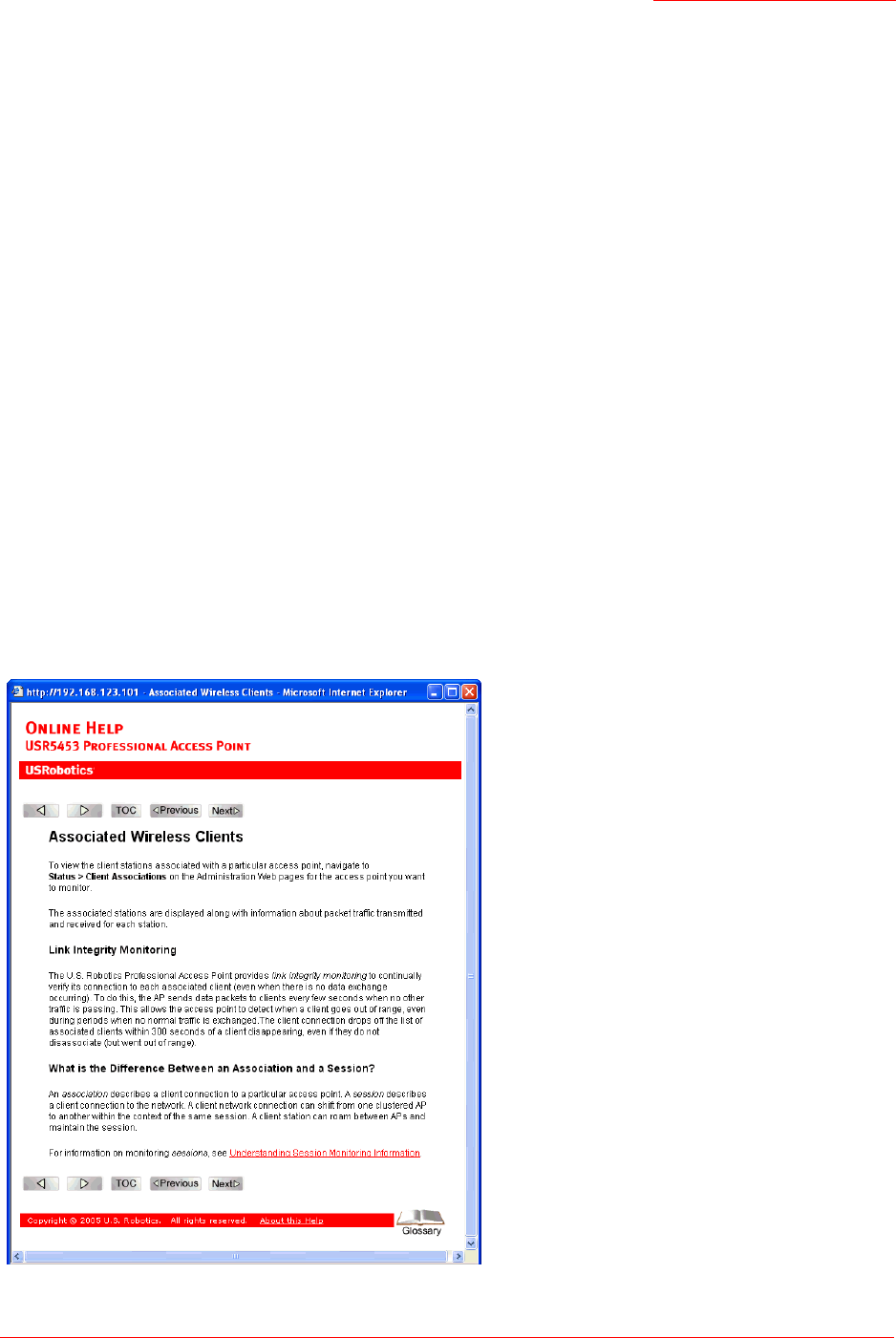
1. Do one of the following to create an Ethernet connection between the access point and your computer:
• Connect one end of an Ethernet cable to the LAN port on the access point and the other end to the
same networking device (such as a router) to which your computer is connected (see Figure 1).
Or
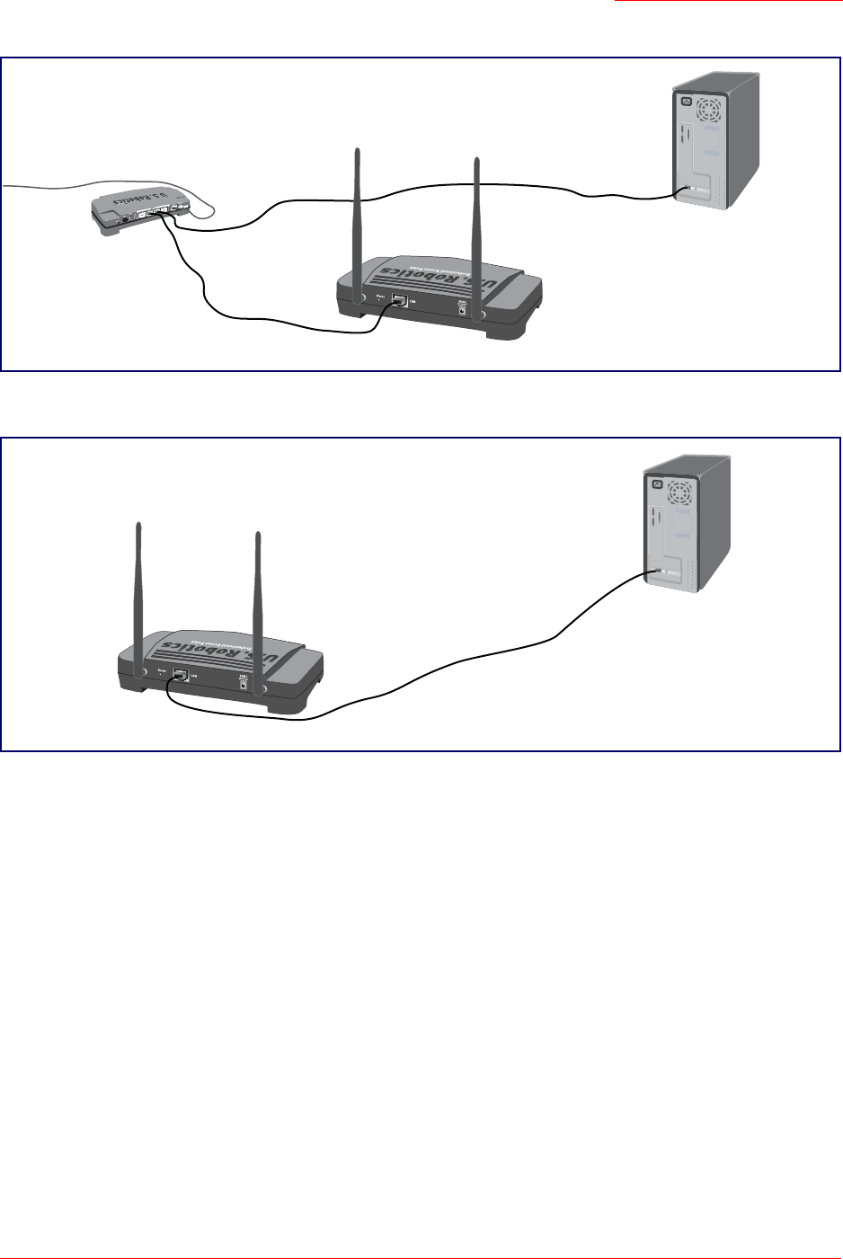
• Connect one end of an Ethernet cable to the LAN port on the access point and the other end of the
cable to the Ethernet port on your computer (see Figure 2).
Initial Connection Notes
If you use a hub, the device that you use must permit broadcast signals from the access point to reach
all other devices on the network. A standard hub should work fine. Some switches, however, do not
allow directed or subnet broadcasts through. You may have to configure the switch to allow directed
broadcasts.
For initial configuration with a direct Ethernet connection and no DHCP server, be sure to set your
computer to a static IP address in the subnet 255.255.255.0. (The default IP address for the access
point is 192.168.1.10.)
If for initial configuration you use a direct Ethernet (wired) connection between the access point and
your computer, you will need to reconfigure the cabling for subsequent startup and deployment of the
access point so that the access point is no longer connected directly to your computer but instead is
connected to the LAN (either via a networking device as shown in Figure 1 or directly).
It is possible to detect access points on the network (using the Detection Utility) with a wireless con-
nection. However, USRobotics strongly advises against using this method. In your environment you
may have no way of knowing whether you are connecting to the intended access point, and the initial
configuration changes required may cause you to lose connectivity with the access point over a wire-
less connection.
Professional Access Point
Administrator Guide
Setting Up and Launching Your Wireless Network - 15
Figure 1. Ethernet Connections When Using DHCP for Initial Configuration.
Figure 2. Ethernet Connections When Using Static IP Address for Initial Configuration.
2. Connect the power adapter to the power port on the back of the access point, and then plug the other
end of the power adapter into a power outlet (preferably, via a surge protector).
A Note About Setting Up Connections for a Guest Network
The Professional Access Point offers a Guest Interface that allows you to configure an access point for
controlled guest access to the network. The same access point can function as a bridge for two different
wireless networks: a secure Internal LAN and a public Guest network. This is done virtually, by defining
two different Virtual LANs in the Web User Interface.
Hardware Connections for a Guest VLAN
If you plan to configure a guest network using VLANs, do the following:
Note to
UK Users
Replace the plug on the power adapter with the UK standard plug that is supplied in your USRo-
botics package. Apply enough pressure to cause a click and firmly seat the new plug in the
adapter.
Administrator Computer
Professional Access Point
Switch
(This computer must have
an IP address on the same
subnet as the access point.)
Administrator Computer
Professional Access Point

Professional Access Point
Administrator Guide
Setting Up and Launching Your Wireless Network - 16
• Connect the LAN port on the access point to a VLAN-capable switch.
• Define VLANs on that switch.
Once you have the required physical connections set up, the rest of the configuration process is
accomplished through the Web User Interface. For information on configuring Guest interface settings in
the Web User Interface, see “Guest Login” on page 111.
Step 3. Run the Detection Utility to find access points on
the network
The Detection Utility is an easy-to-use utility for discovering and identifying new Professional Access
Points. The Detection Utility scans the network looking for access points, and displays ID details on those
it finds.
Run the Installation CD-ROM on a laptop or computer that is connected to the same network as your
access points and use it to step through the discovery process as follows:
1. Insert the Installation CD-ROM into the CD-ROM drive on your computer and select Setup from the
menu.
If the CD-ROM does not start automatically, navigate to the CD-ROM drive and double-click setup.exe.
If you receive a Windows Security Alert from your Windows Firewall, click Unblock to enable the java
program to access your network. If network access is blocked, the Detection Utility cannot find your
access point.
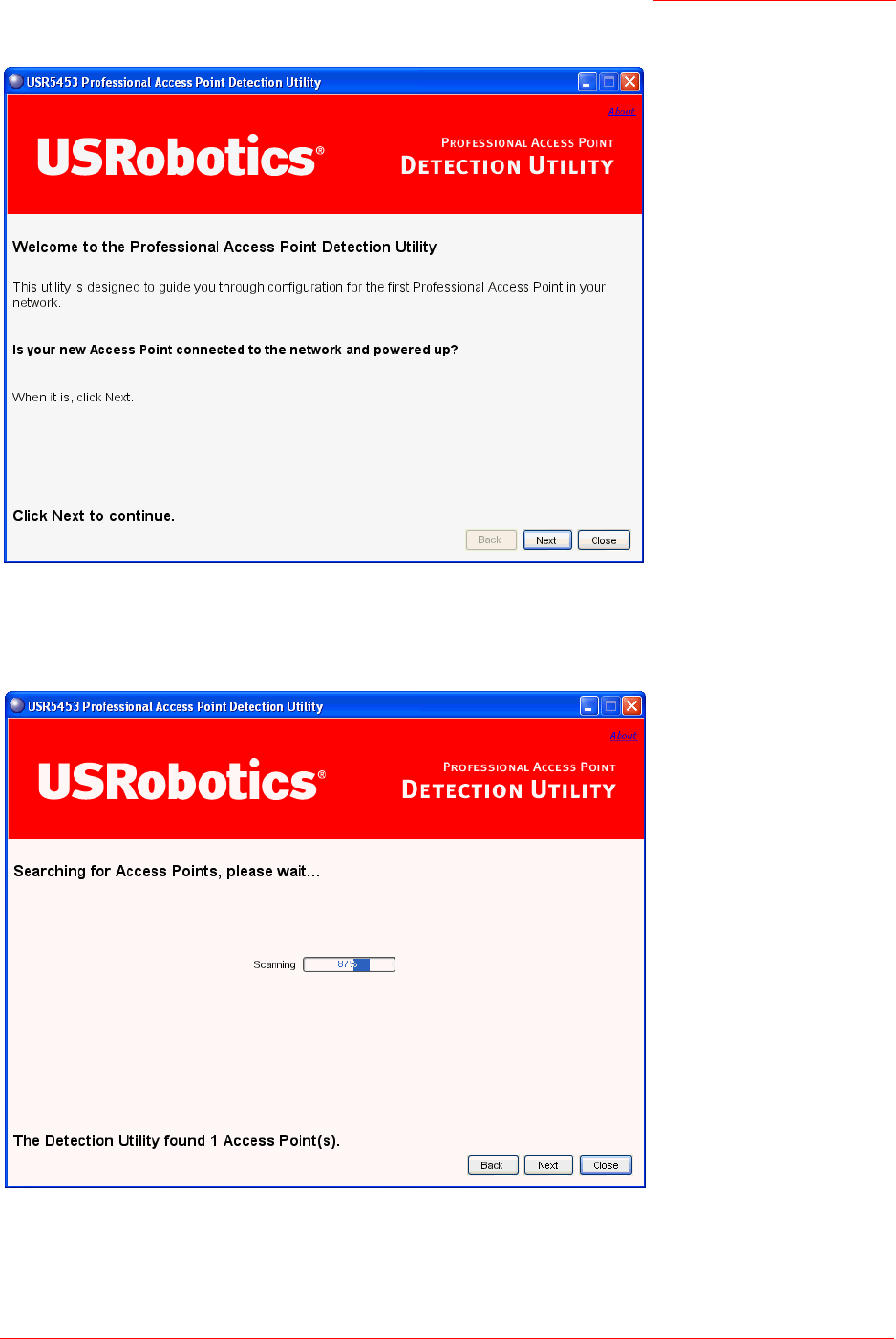
The Detection Utility Welcome screen is displayed.
Notes and Cautions
• Keep in mind that the Detection Utility recognizes and configures only USRobotics Professional
Access Points. The Detection Utility will not find any other devices.
• Run the Detection Utility only in the subnet of the internal network (SSID). Do not run the Detec-
tion Utility on the guest subnetwork.
• The Detection Utility will find only those access points that have IP addresses. IP addresses are
dynamically assigned to APs if you have a DHCP server running on the network. Keep in mind that
if you deploy the access point on a network with no DHCP server, the default static IP address
(192.168.1.10) will be used.
Use caution with non-DHCP enabled networks: Do not deploy more than one new access point
on a non-DHCP network because they will use the same default static IP addresses and conflict
with each other. (For more information, see “Understanding Dynamic and Static IP Addressing on
the Professional Access Point” on page 10 and “How Does the Access Point Obtain an IP Address
at Startup?” on page 10.)
Professional Access Point
Administrator Guide
Setting Up and Launching Your Wireless Network - 17
2. Click Next to search for access points. Wait for the search to complete, or until the Detection Utility has
found your new access points.
Professional Access Point
Administrator Guide
Setting Up and Launching Your Wireless Network - 18
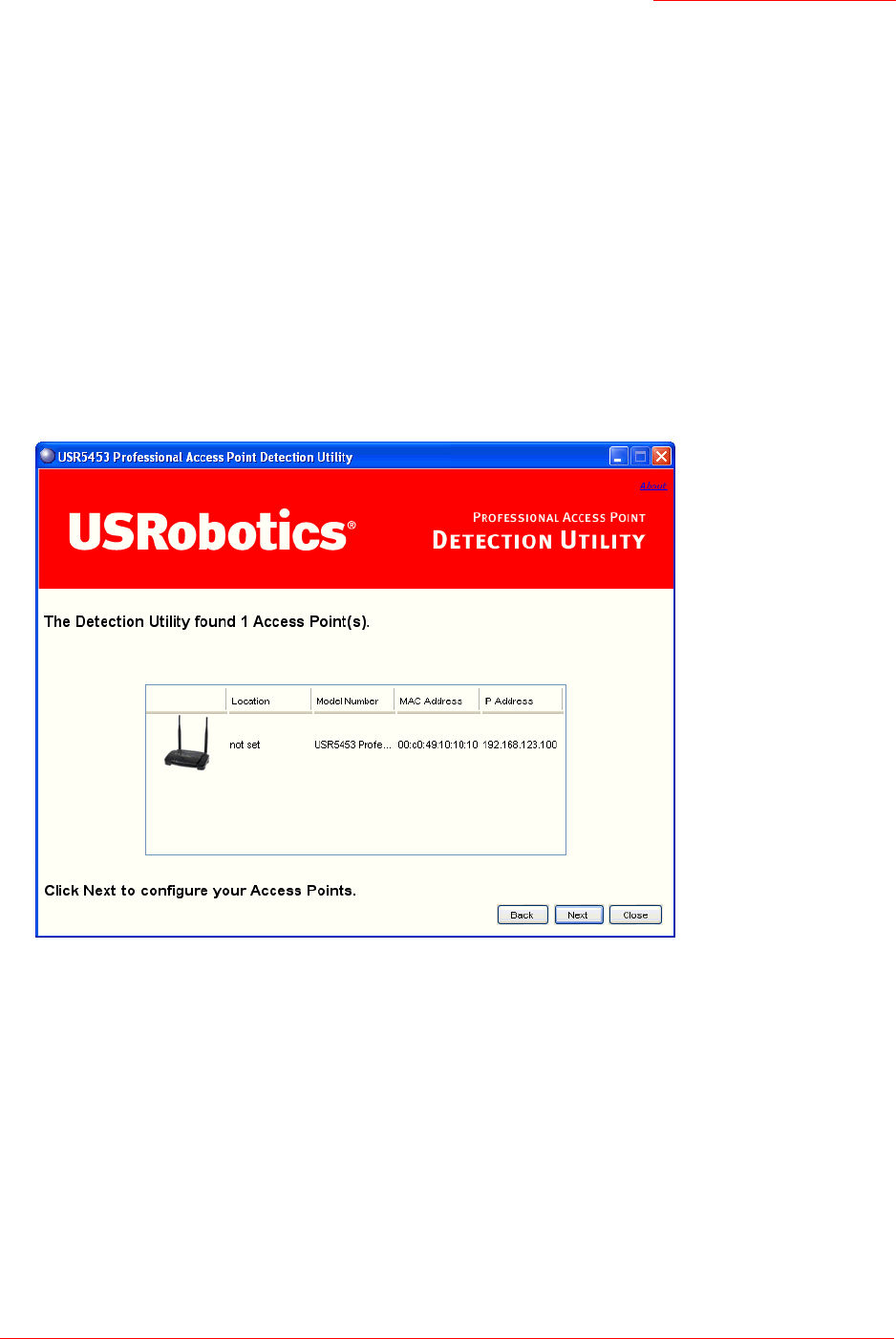
3. Review the list of access points found.
The Detection Utility will detect the IP addresses of Professional Access Points. Access points are
listed with their locations,MAC addresses, and IP Addresses. If you are installing the first access point
on a single-access-point network, only one entry will be displayed on this screen
Verify the MAC addresses shown here against the Professional Access Point’s LAN MAC address.
(You can find the LAN MAC on the label on the bottom of the access point.) This will be especially
helpful later in providing or modifying the descriptive Location name for each access point.
Click Next.
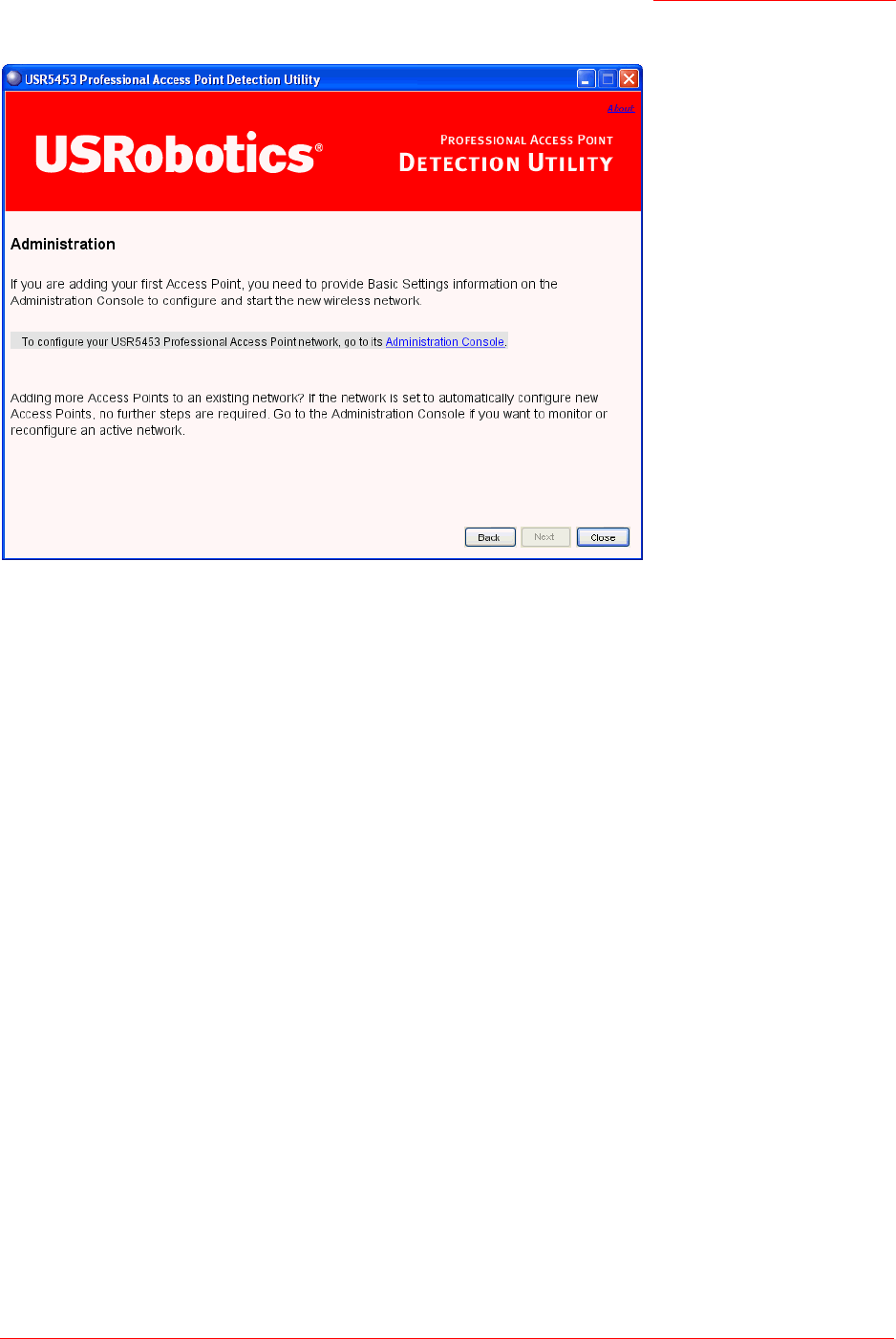
4. Go to the Access Point Web User Interface by clicking the link provided on the Detection Utility page.
Note
If no access points are found, the Detection Utility indicates this and presents troubleshooting informa-
tion about your LAN and power connections. Once you have checked hardware power and Ethernet
connections, you can click the Detection Utility Back button to search again for access points.
Professional Access Point
Administrator Guide
Setting Up and Launching Your Wireless Network - 19
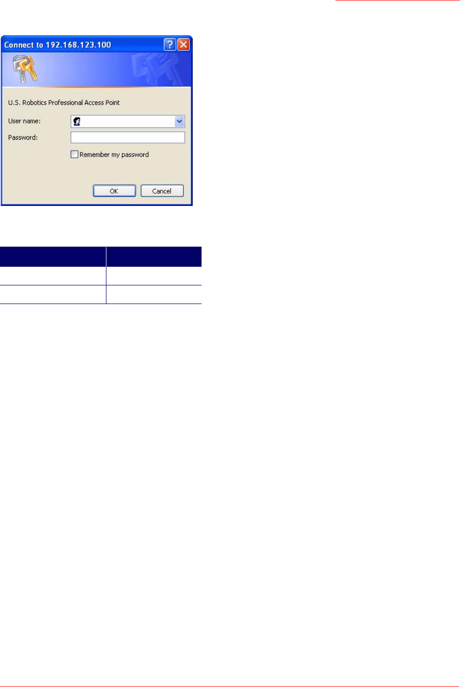
Step 4. Log on to the Web User Interface
When you follow the link from the Detection Utility to the Professional Access Point Web User Interface,
you are prompted for a user name and password.
Note
The Detection Utility provides a link to the Web User Interface via the IP address of the first
Professional Access Point.The Web User Interface is a management tool that you can access via the
IP address for any access point in a cluster. (For more information about clustering see
“Understanding Clustering” on page 34.)
Professional Access Point
Administrator Guide
Setting Up and Launching Your Wireless Network - 20
The defaults for user name and password are as follows.
Enter the user name and password and click OK.
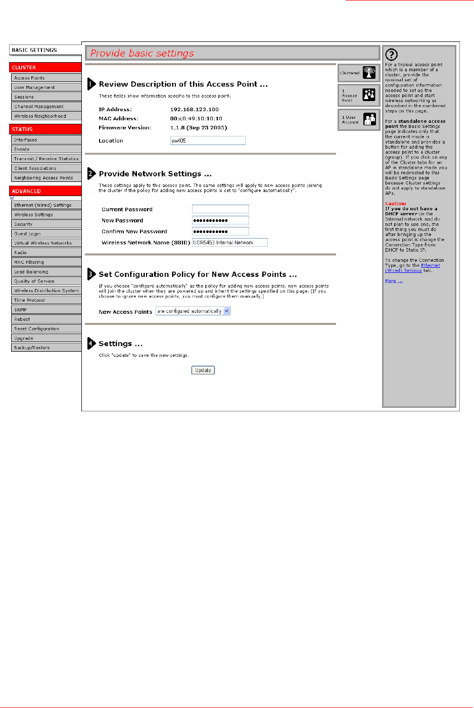
Viewing Basic Settings for Access Points
When you first log in, the Basic Settings page for Professional Access Point administration is displayed.
These are global settings for all access points that are members of the cluster and, if automatic
configuration is specified, for any new access points that are added later.
Field Default Setting
Username admin
Password admin
Professional Access Point
Administrator Guide
Setting Up and Launching Your Wireless Network - 21
Step 5. Configure Basic Settings and start the wireless
network
Provide a minimal set of configuration information by defining the basic settings for your wireless network.
These settings are all available on the Basic Settings page of the Web User Interface, and are categorized
into steps 1-4 on the Web page.
For a detailed description of these Basic Settings and how to properly configure them, please see “Basic
Settings” on page 25. Summarized briefly, the steps are:
1. Review Description of this Access Point.
Provide IP addressing information. For more information, see “Review / Describe the Access Point” on
page 27.
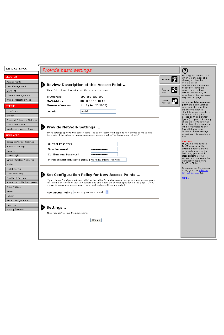
2. Provide Network Settings.

Professional Access Point
Administrator Guide
Setting Up and Launching Your Wireless Network - 22
Provide a new administrator password for clustered access points. For more information, see “Provide
Administrator Password and Wireless Network Name” on page 28.
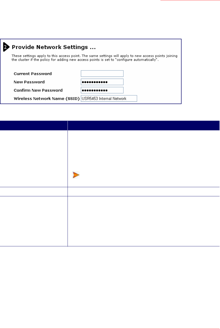
3. Set Configuration Policy for New Access Points.
Choose to configure new access points automatically (as new members of the cluster) or ignore new
access points.
If you set a configuration policy to configure new access points automatically, new access points
added to this network will join the cluster and be configured automatically based on the settings you
defined here. Updates to the Network settings on any cluster member will be shared with all other
access points in the group.
If you chose to ignore new access points, any additional access points will run in standalone mode.
In standalone mode, an access point does not share the cluster configuration with other access points;
it must be configured manually.
You can always update the settings on a standalone access point to have it join the cluster. You can
also remove an access point from a cluster thereby switching it to run in standalone mode.
For more information, see “Set Configuration Policy for New Access Points” on page 29.
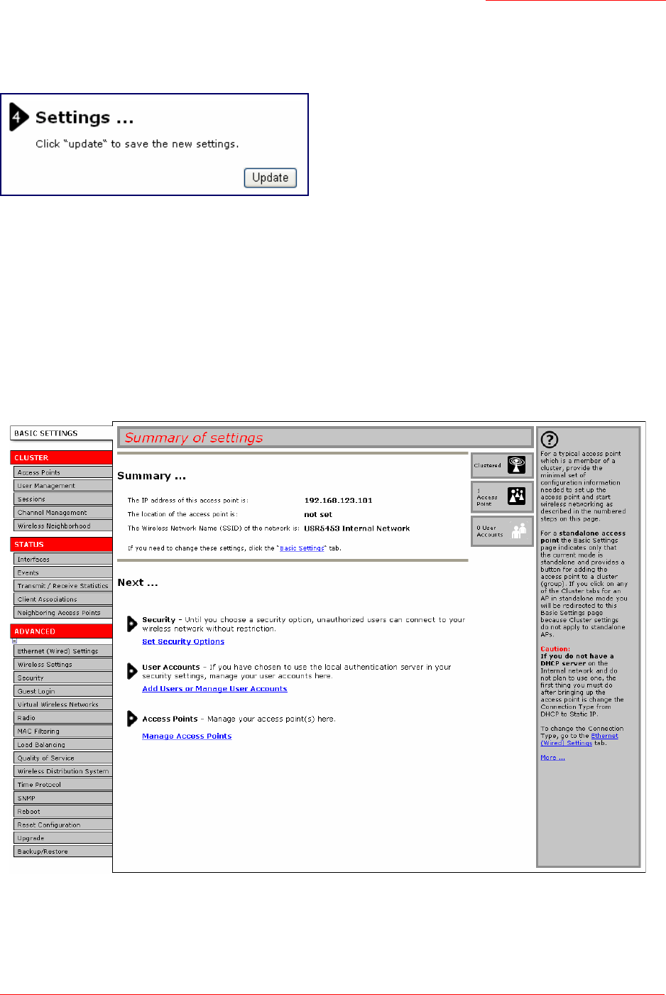
4. Start Wireless Networking
Click the Update button to activate the wireless network with these new settings. For more information,
see “Update Basic Settings” on page 30.
Default Configuration
If you follow the steps above and accept all the defaults, the access point will have the default
configuration described in “Default Settings for the Professional Access Point” on page 6.
Professional Access Point
Administrator Guide
Setting Up and Launching Your Wireless Network - 23
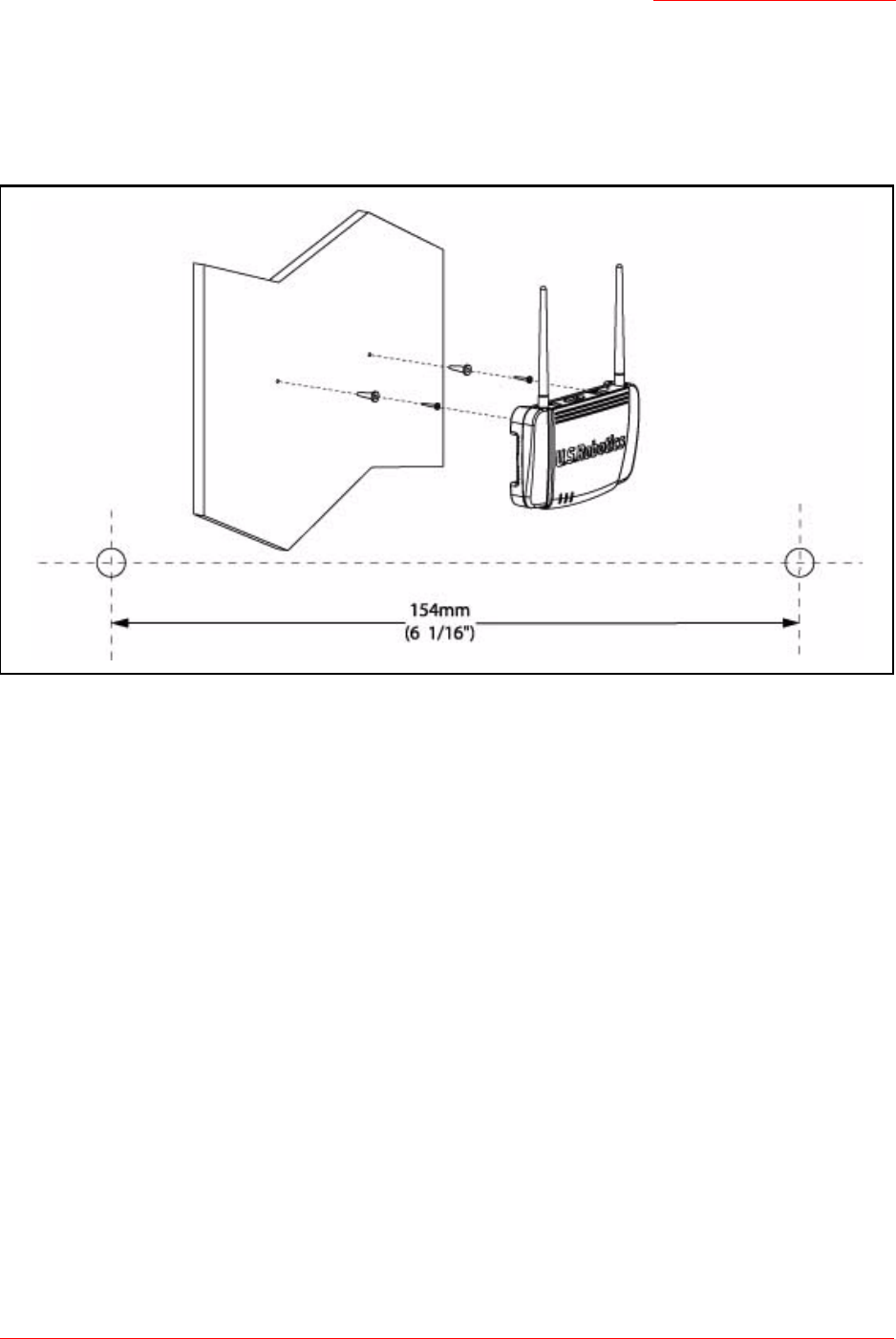
Wall Mounting the Access Point
The access point has keyhole openings for easy wall mounting. To expose the openings, remove the pads
from the rear feet. You can then mount the access point to the wall with two anchored screws, as shown in
the following illustration:
What’s Next?
Next, make sure the access point is connected to the LAN, bring up your wireless clients, and connect the
clients to the network. Once you have tested the basics of your wireless network, you can enable more
security and fine-tune the access point by modifying its advanced configuration features.
Make Sure the Access Point is Connected to the LAN
If you configured the access point and administrator PC by connecting both into a network hub, then your
access point is already connected to the LAN.
If you configured the access point using a direct wired connection via Ethernet cable from your computer to
the access point, do the following:
1. Disconnect the Ethernet cable from the computer.
2. Connect the free end of the cable to the LAN.
3. Connect your computer to the LAN either via Ethernet cable or wireless client card.

Professional Access Point
Administrator Guide
Setting Up and Launching Your Wireless Network - 24
Test LAN Connectivity with Wireless Clients
Test the Professional Access Point by trying to detect it and associate with it from a wireless client device.
(See “Wireless Client Computers” on page 9 in the Pre-Launch Checklist: Default Settings and Supported
Administrator/Client Platforms for information on requirements for these clients.)
Secure and Fine-Tune the Access Point Using Advanced Features
Once the wireless network is operational and has been tested with a wireless client, you can add more
security, add users, configure a Guest interface, and fine-tune the access point performance settings.

Professional Access Point
Administrator Guide
Basic Settings - 25
Web User Interface
This part of the Professional Access Point Administrator Guide covers usage of the Web User Interface
with each section corresponding to a menu section:
•“Basic Settings” on page 25
•“Cluster” on page 33
•“Status” on page 67
•“Advanced” on page 79
Basic Settings
The basic configuration tasks are described in the following sections:
•Navigating to Basic Settings
•Review / Describe the Access Point
•Provide Administrator Password and Wireless Network Name
•Set Configuration Policy for New Access Points
•Update Basic Settings
•Summary of Settings
•Basic Settings for a Standalone Access Point
•Your Network at a Glance: Understanding Indicator Icons
Professional Access Point
Administrator Guide
Basic Settings - 26
Navigating to Basic Settings
To configure initial settings, click Basic Settings.
If you use the Detection Utility to link to the Web User Interface, the Basic Settings page is displayed by
default.
Fill in the fields on the Basic Settings page as described below.

Professional Access Point
Administrator Guide
Basic Settings - 27
Review / Describe the Access Point
Field Description
IP Address The IP address assigned to this access point. This field is not editable because
the IP address is already assigned (either via DHCP, or statically through the
Ethernet (wired) settings as described in “Configuring Guest Interface Ethernet
(Wired) Settings” on page 85).
MAC Address The MAC address of the access point.
A MAC address is a permanent, unique hardware address for any device that
represents an interface to the network. The MAC address is assigned by the
manufacturer. You cannot change the MAC address. It is displayed for infor-
mational purposes as a unique identifier for an interface.
The address shown here is the MAC address for the bridge (
br0
). This is the
address by which the access point is known externally to other networks.
To see MAC addresses for Guest and Internal interfaces on the access point,
go to the Status menu and view the Interface tab.
Firmware Version Version information about the firmware currently installed on the access point.
As new versions of the Professional Access Point firmware become available,
you can upgrade the firmware on your access points to take advantages of
new features and enhancements.
For instructions on how to upgrade the firmware, see “Upgrade” on page 160.
Location Specify a location description for this access point.
Professional Access Point
Administrator Guide
Basic Settings - 28
Provide Administrator Password and Wireless Network
Name
Field Description
Administrator Password Enter a new administrator password. The characters you enter will be dis-
played as "
•
" characters to prevent others from seeing your password as you
type.
The Administrator password must be an alphanumeric string of up to 8 charac-
ters. Do not use special characters or spaces.
As an immediate first step in securing your wireless network, USRobot-
ics recommends that you change the administrator password from the
default.
Administrator Password (again) Re-enter the new password to confirm that you typed it as you intended.
Wireless Network Name (SSID) Enter a name for the wireless network. This name will apply to all access points
on this network. As you add more access points, they will share this SSID.
The Service Set Identifier (SSID) must be an alphanumeric string of up to 32
characters
Note: If you are connected as a wireless client to the access point that you are
administering, resetting the SSID will cause you to lose connectivity to the
access point. You will need to reconnect using the new SSID.
Note
The Professional Access Point is not designed for multiple, simultaneous configuration changes. If
more than one administrator is making changes to the configuration at the same time, all access points
in the cluster will stay synchronized, but there is no guarantee that all changes specified by all of the
administrators will be applied.
Professional Access Point
Administrator Guide
Basic Settings - 29
Set Configuration Policy for New Access Points
Field Description
New Access Points Choose the policy that you want to put in effect for adding New Access Points to
the network.
• If you choose are configured automatically, then when a new access point
is added to the network it automatically joins the existing cluster. The cluster
configuration is copied to the new access point, and no manual configura-
tion is required to deploy it.
• If you choose are ignored, new access points will not join the cluster; they
will be considered standalone. You need to configure standalone access
points manually via the Detection Utility and the Web User Interface residing
on the standalone access points. (To get to the Web page for a standalone
access point, use its IP address in a URL as follows: http://IPAddressOfAc-
cessPoint.)
Note: If you change the policy so that new access points are ignored, then any
new access points you add to the network will not join the cluster. Existing clus-
tered access points will not be aware of these standalone APs. Therefore, if
you are viewing the Web User Interface via the IP address of a clustered
access point, the new standalone APs will not show up in the list of access
points on the Cluster menu’s Access Points page. The only way to see a stan-
dalone access point is to browse to it directly by using its IP address as the
URL.
If you later change the policy back to the default so that new access points are
configured automatically, all subsequent new APs will automatically join the
cluster. Standalone APs, however, will stay in standalone mode until you
explicitly add them to the cluster.
For information on how to add standalone APs to the cluster, see “Adding an
Access Point to a Cluster” on page 40.
Professional Access Point
Administrator Guide
Basic Settings - 30
Update Basic Settings
When you have reviewed the new configuration, click Update to apply the settings and deploy the access
points as a wireless network.
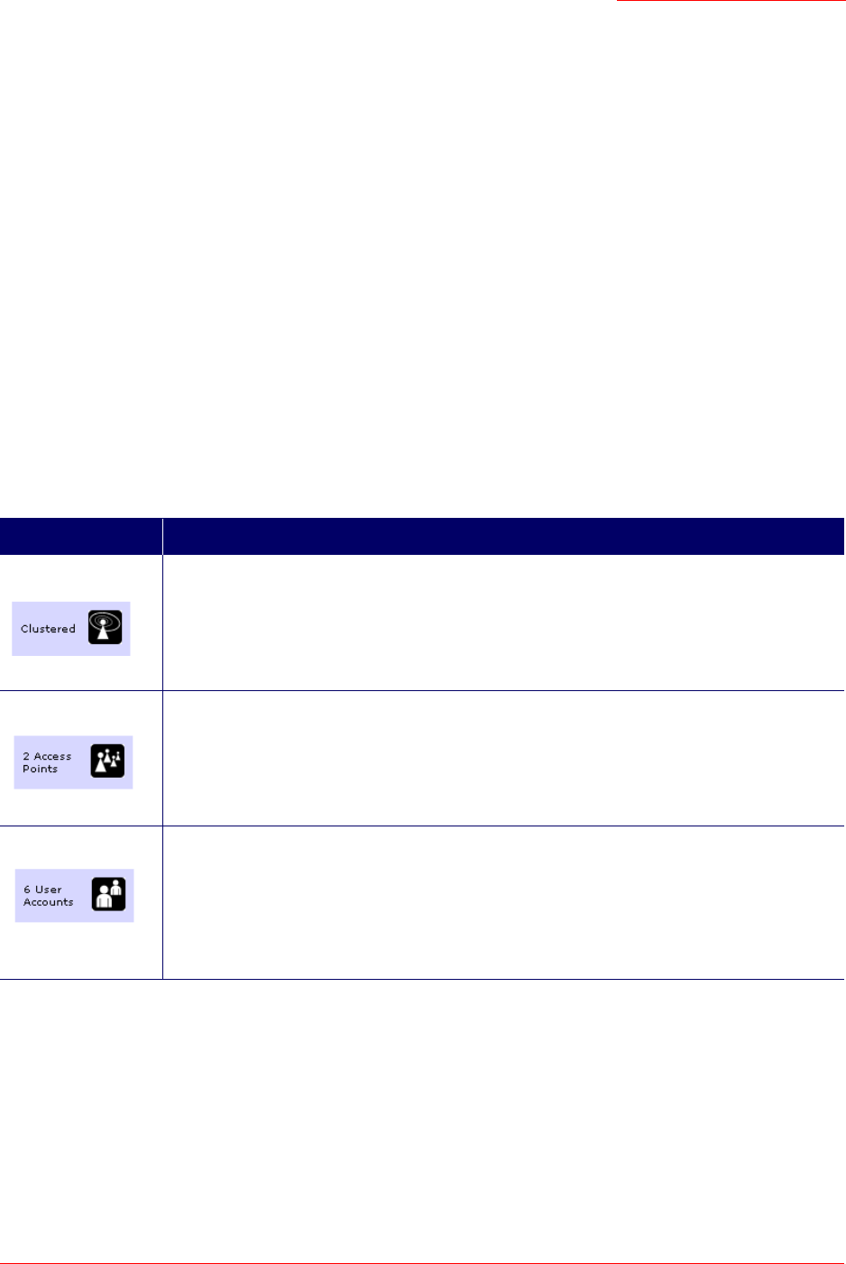
Summary of Settings
When you update the Basic Settings, a summary of the new settings is shown along with information
about next steps.
At initial startup, no security is in place on the access point. An important next step is to configure security,
as described in “Security” on page 91.
Professional Access Point
Administrator Guide
Basic Settings - 31
At this point if you click Basic Settings again, the summary of settings page is replaced by the standard
Basic Settings configuration options.
Basic Settings for a Standalone Access Point
The Basic Settings page for a standalone access point indicates only that the current mode is standalone
and provides a button for adding the access point to a cluster (group). If you click on any of the Cluster
tabs on the Web User Interface pages for an access point in standalone mode, you will be redirected to the
Basic Settings page because Cluster settings do not apply to standalone APs.
For more information see “Standalone Mode” on page 37 and “Adding an Access Point to a Cluster” on
page 40.
Your Network at a Glance: Understanding Indicator Icons
All the Cluster settings tabs on the Web User Interface include icons that show current network activity.
Icon Description
When one or more APs on your network are available for service, the Wireless Network
Available icon is shown. The clustering icon indicates whether the current access point is
Clustered or Not Clustered (that is, standalone).
For information about clustering, see “Understanding Clustering” on page 34.
The number of access points available for service on this network is indicated by the Access
Points icon.
For information about managing access points, see “Access Points” on page 33.
The number of user accounts created and enabled on this network is indicated by the User
Accounts icon.
For information about setting up user accounts on the access point for use with the built-in
authentication server, see “User Management” on page 43. See also “IEEE 802.1x” on
page 104 and “WPA/WPA2 Enterprise (RADIUS)” on page 107, which are the two security
modes that offer the option of using the built-in authentication server.

Professional Access Point
Administrator Guide
Basic Settings - 32

Professional Access Point
Administrator Guide
Access Points - 33
Cluster
This section covers the Web User Interface Cluster items:
•“Access Points” on page 33
•“User Management” on page 43
•“Sessions” on page 49
•“Channel Management” on page 53
•“Wireless Neighborhood” on page 61
Access Points
The Professional Access Point shows current basic configuration settings for clustered access points
(location, IP address, MAC address, status, and availability) and provides a way of navigating to the full
configuration for specific APs if they are cluster members.
Standalone access points or those which are not members of this cluster do not show up in this listing. To
configure standalone access points, you must discover (via the Detection Utility) or know the IP address of
the access point and by using its IP address in a URL (
http://IPAddressOfAccessPoint
).
The following topics are covered:
•Navigating to Access Points Management
•Understanding Clustering
•What is a Cluster?
•How Many APs Can a Cluster Support?
•What Kinds of APs Can Cluster?
•Which Settings are Shared as Part of the Cluster Configuration and Which Are Not?
•Cluster Mode
•Standalone Mode
•Cluster Formation
Note
The Professional Access Point is not designed for multiple, simultaneous configuration changes. If you
have a network that includes multiple access points, and more than one administrator is logged on to
the Web User Interface and making changes to the configuration, all access points in the cluster will
stay synchronized but there is no guarantee that all configuration changes specified by multiple users
will be applied.
Professional Access Point
Administrator Guide
Access Points - 34
•Cluster Size and Membership
•Intra-Cluster Security
•Auto-Synchronization of Cluster Configuration
•Understanding Access Point Settings
•Modifying the Location Description
•Removing an Access Point from the Cluster
•Adding an Access Point to a Cluster
•Navigating to the Web User Interface for a Specific Access Point
Navigating to Access Points Management
To view or edit information on access points in a cluster, click the Cluster menu’s Access Points tab.
Understanding Clustering
A key feature of the Professional Access Point is the ability to form a dynamic, configuration-aware group
(called a cluster) with other Professional Access Points in a network in the same subnet. Access points can

Professional Access Point
Administrator Guide
Access Points - 35
participate in a self-organizing cluster which makes it easier for you to deploy, administer, and secure your
wireless network. The cluster provides a single point of administration and lets you view the deployment of
access points as a single wireless network rather than a series of separate wireless devices.
What is a Cluster?
A cluster is a group of access points which are coordinated as a single group via Professional Access
Point administration. You cannot create multiple clusters on a single wireless network (SSID). Only one
cluster per wireless network is supported.
How Many APs Can a Cluster Support?
Up to eight access points are supported in a cluster at any one time. If a new access point is added to a
network with a cluster that is already at full capacity, the new access point is added in standalone mode.
Note that when the cluster is full, extra APs are added in stand-alone mode regardless of the configuration
policy in effect for new access points.
For related information, see “Cluster Mode” on page 37, “Standalone Mode” on page 37, and “Set
Configuration Policy for New Access Points” on page 29.
What Kinds of APs Can Cluster?
A single Professional Access Point can form a cluster with itself (a cluster of one) and with other
Professional Access Points of the same model. In order to be members of the same cluster, access points
must be on the same LAN.
Having a mix of APs on the network does not adversely affect Professional Access Point clustering in any
way. However, access points of other types will not join the cluster. Those APs must be administered with
their own associated administration tools.
Which Settings are Shared as Part of the Cluster Configuration and Which Are Not?
Most configuration settings defined via the Professional Access Point Web User Interface will be
propagated to cluster members as a part of the cluster configuration.
Settings Shared in the Cluster Configuration
The cluster configuration includes:
• Network name (SSID)
• Administrator Password
• Configuration policy
• User accounts and authentication
• Wireless interface settings
• Guest Welcome screen settings
• Network Time Protocol (NTP) settings

Professional Access Point
Administrator Guide
Access Points - 36
• Radio settings
The following radio settings are synchronized across clusters:
•Mode
• Channel
• Fragmentation Threshold
• RTS Threshold
• Rate Sets
The following radio settings are not synchronized across clusters:
• Beacon Interval
•DTIM Period
• Maximum Stations
• Transmit Power
• Security settings
•QoS queue parameters
• MAC address filtering
Settings Not Shared by the Cluster
The few exceptions (settings not shared among clustered access points) are the following; most of these,
by their nature, must be unique:
• IP addresses
• MAC addresses
• Location descriptions
• Load Balancing settings
• WDS bridges
• Ethernet (Wired) Settings, including enabling or disabling Guest access
• Guest interface configuration
Settings that are not shared must be configured individually in the Web User Interface for each access
Note
When Channel Planning is enabled, the radio Channel is not synchronized across the cluster.
See “Stopping/Starting Automatic Channel Assignment” on page 56.

Professional Access Point
Administrator Guide
Access Points - 37
point. To access the Web User Interface for an access point that is a member of the current cluster, click
the Cluster menu’s Access Points tab in the Web User Interface of the current access point, then click the
member access point’s IP Address link.
Cluster Mode
When an access point is a cluster member, it is considered to be in cluster mode. You define whether you
want new access points to join the cluster or not via the configuration policy you set in the Basic Settings.
(See “Set Configuration Policy for New Access Points” on page 29.) You can reset an access point in
cluster mode to standalone mode. (See “Removing an Access Point from the Cluster” on page 39.)
Standalone Mode
The Professional Access Point can be configured in standalone mode. In standalone mode, an access
point is not a member of the cluster and does not share the cluster configuration, but rather requires
manual configuration that is not shared with other access points. (See “Set Configuration Policy for New
Access Points” on page 29 and “Removing an Access Point from the Cluster” on page 39.)
Standalone access points are not listed on the Cluster menu’s Access Points page in the Web User
Interfaces of APs that are cluster members. You need to know the IP address for a standalone access
point in order to configure and manage it directly. (See “Navigating to an Access Point by Using its IP
Address in a URL” on page 40.)
The Basic Settings tab for a standalone access point indicates only that the current mode is standalone
and provides a button for adding the access point to a cluster (group). If you click any of the Cluster tabs in
the Web User Interface for a standalone access point, you will be redirected to the Basic Settings page
because Cluster settings do not apply to standalone APs.
You can re-enable cluster mode on a standalone access point. (See “Adding an Access Point to a Cluster”
on page 40.)
Cluster Formation
A cluster is formed when the first Professional Access Point is configured. (See “Setting Up and Launching
Your Wireless Network” on page 13 and “Basic Settings” on page 25.)
If a cluster configuration policy in place, when a new access point is deployed, it attempts to rendezvous
with an existing cluster.
If it is unable to locate a cluster, then it establishes a new cluster on its own.
If it locates a cluster but is rejected because the cluster is full or because the clustering policy is to ignore
new access points, then the access point deploys in standalone mode.
Note
When the cluster is full (eight APs is the limit), extra APs are added in stand-alone mode regardless of
the configuration policy in effect for new access points.
Note
When the cluster is full, new APs are added in stand-alone mode regardless of the configuration policy
in effect for new access points. A cluster supports a maximum of eight access points.

Professional Access Point
Administrator Guide
Access Points - 38
Cluster Size and Membership
The upper limit of a cluster is eight access points. The Cluster Web User Interface pages provide a visual
indicator of the number of access points in the current cluster and warn when the cluster has reached
capacity.
Intra-Cluster Security
To ensure that the security of the cluster as a whole is equivalent to the security of a single access point,
communication of certain data between access points in a cluster is accomplished through Secure Sockets
Layer (typically referred to as SSL) with private key encryption.
Both the cluster configuration file and the user database are transmitted among access points using SSL.
Auto-Synchronization of Cluster Configuration
If you are making changes to the access point configuration that require a relatively large amount of
processing (such as adding several new users), you may encounter a synchronization progress bar after
clicking Update on any of the Web User Interface pages. The progress bar indicates that the system is busy
performing an auto-synchronization of the updated configuration across all APs in the cluster. The Web
User Interface pages are not editable during the auto-synch.
Note that auto-synchronization always occurs during configuration updates that affect the cluster, but the
processing time is usually negligible. The auto-synchronization progress bar is displayed only for longer-
than-usual wait times.
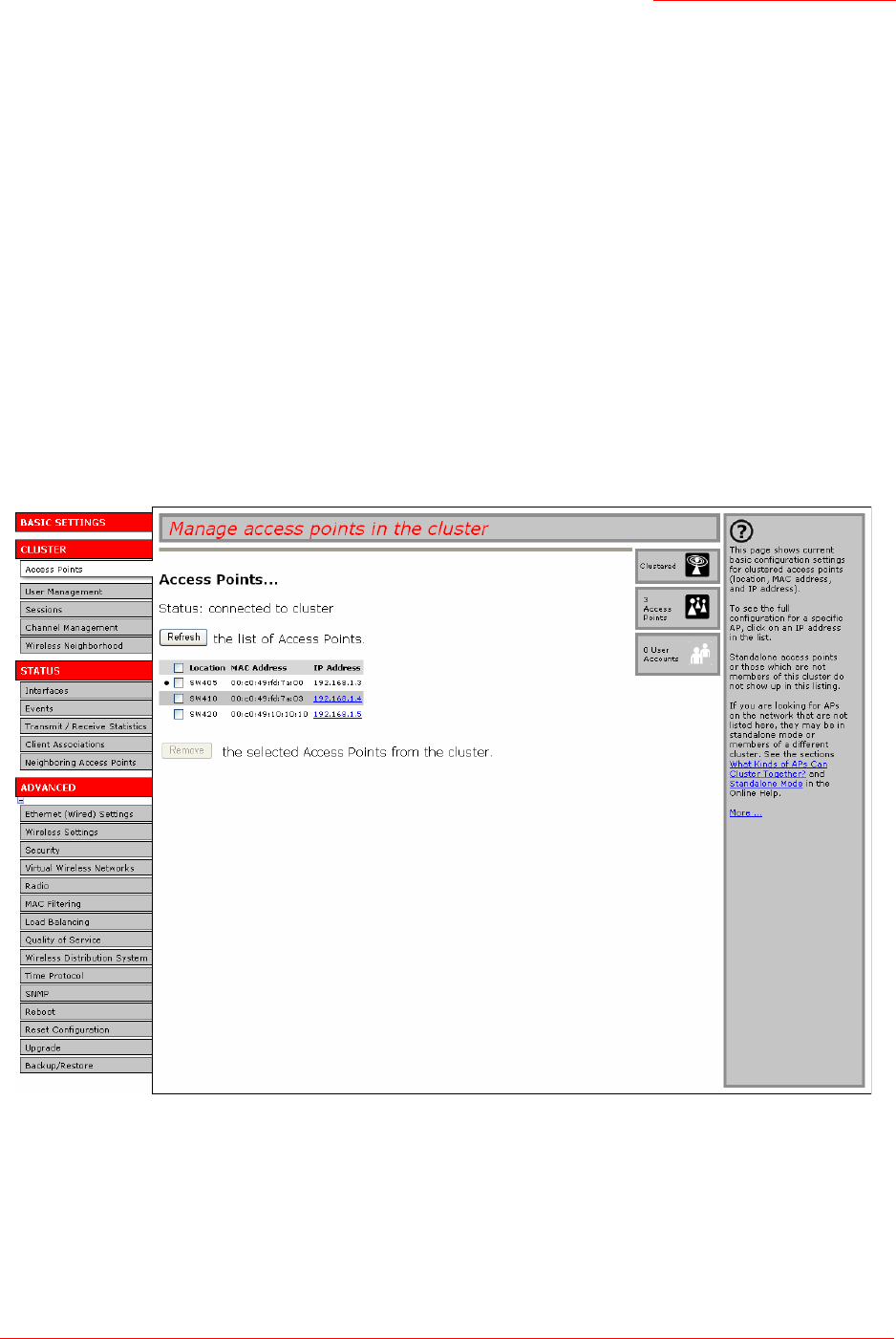
Understanding Access Point Settings
The Access Points tab provides information about all access points in the cluster.
From this tab, you can view location descriptions, IP addresses, enable (activate) or disable (deactivate)
clustered access points, and remove access points from the cluster. You can also modify the location
description for an access point.
The IP address links provide a way to navigate to configuration settings and data on an access point.
Standalone access points (those which are not members of the cluster) are not shown on this page.

Professional Access Point
Administrator Guide
Access Points - 39
The following table describes the access point settings and information display in detail.
Modifying the Location Description
To make modifications to the location description:
1. Navigate to the Basic Settings page.
2. Update the Location description in section 1 under Review Description of this Access Point.
3. Click Update button to apply the changes.
Removing an Access Point from the Cluster
To remove an access point from the cluster, do the following.
1. Select the check box next to the access point.
2. Click Remove from Cluster.
The change will be reflected under Status for that access point; the access point will now show as
standalone (instead of cluster).
Field Description
Location Description of the access point’s physical location.
MAC Address Media Access Control (MAC) address of the access point.
A MAC address is a permanent, unique hardware address for any device that repre-
sents an interface to the network. The MAC address is assigned by the manufacturer.
You cannot change the MAC address. It is provided here for informational purposes as a
unique identifier for the access point.
The address shown here is the MAC address for the bridge (
br0
). This is the address
by which the access point is known externally to other networks.
To see MAC addresses for Guest and Internal interfaces on the access point, see the
Status menu’s Interfaces page.
IP Address Specifies the IP address for the access point. Each IP address is a link to the Web User
Interface for that access point. You can use the links to navigate to the Web User Inter-
face for a specific access point. This is useful for viewing data on a specific access point
to make sure a cluster member is picking up cluster configuration changes, to configure
advanced settings on a particular access point, or to switch a standalone access point to
cluster mode.
Note
In some situations, it is possible for the cluster to lose synchronization. If, after removing an access
point from the cluster, the access point list still reflects the deleted access point or shows an incom-
plete display, refer to the information on Cluster Recovery in “Troubleshooting”.

Professional Access Point
Administrator Guide
Access Points - 40
Adding an Access Point to a Cluster
To add an access point that is currently in standalone mode back into a cluster, do the following.
1. Go to the Web User Interface for the standalone access point. (See “Navigating to an Access Point by
Using its IP Address in a URL” on page 40.)
The Web User Interface pages for the standalone access point are displayed.
2. Click the Basic Settings tab in the Administration pages for the standalone access point.
The Basic Settings tab for a standalone access point indicates that the current mode is standalone and
provides a button for adding the access point to a cluster (group).
3. Click the Join Cluster button.
The access point is now a cluster member. Its Status (Mode) on the Cluster menu’s Access Points
page now indicates cluster instead of standalone.
Navigating to the Web User Interface for a Specific Access Point
In general, the Professional Access Point is designed for central management of clustered access points.
All access points in a cluster reflect the same configuration. In this case, it does not matter which access
point you actually connect to for administration.
There may be situations, however, when you want to view or manage information on a particular access
point. For example, you might want to check status information such as client associations or events for an
access point. You can navigate to the Web User Interface for an individual access point by clicking the
access point’s IP address link on the Access Points tab.
All clustered access points are shown on the Cluster menu’s Access Points page. To navigate to clustered
access points, you can simply click on the IP address for a specific cluster member shown in the list.
Navigating to an Access Point by Using its IP Address in a URL
You can also link to the Web User Interface of a specific access point by entering the IP address for that
access point as a URL directly into a Web browser address bar in the following form:
http://IPAddressOfAccessPoint
where IPAddressOfAccessPoint is the address of the particular access point that you want to monitor or
configure.
For a standalone access point, this is the only way to navigate to the configuration information.
If you do not know the IP address for a standalone access point, use the Detection Utility to find all APs on
the network and you should be able to derive which ones are standalone by comparing the Detection Utility
Note
If you click any of the Cluster tabs in the Web User Interface for an access point in standalone
mode, you will be redirected to the Basic Settings page because Cluster settings do not apply to
standalone APs.

Professional Access Point
Administrator Guide
Access Points - 41
findings with access points listed on the Cluster menu’s Access Points page. The APs that the Detection
Utility finds that are not shown on the Access Points page are probably standalone APs. (For more
information on using the Detection Utility, see “Step 3. Run the Detection Utility to find access points on the
network” on page 16.)

Professional Access Point
Administrator Guide
Access Points - 42

Professional Access Point
Administrator Guide
User Management - 43
User Management
The Professional Access Point includes user management capabilities for controlling access to your
access points.
User management and authentication must always be used in conjunction with the following two security
modes, which require use of a RADIUS server for user authentication and management.
• IEEE 802.1x mode (see “IEEE 802.1x” on page 104 in Security)
• WPA with RADIUS mode (see “WPA/WPA2 Enterprise (RADIUS)” on page 107 in Security)
You have the option of using either the internal RADIUS server embedded in the Professional Access
Point or an external RADIUS server that you provide. If you use the embedded RADIUS server, use this
Administration Web page on the access point to set up and manage user accounts. If you are using an
external RADIUS server, you will need to set up and manage user accounts for that server in the Web User
Interface.
On the User Management page, you can create, edit, remove, and view user accounts. Each user account
consists of a user name and password. The set of users specified on the User Management page
represent approved clients that can log in and use one or more access points to access local and possibly
external networks via your wireless network.
The following topics are covered:
•Navigating to User Management for Clustered Access Points
•Viewing User Accounts
•Adding a User
•Editing a User Account
•Enabling and Disabling User Accounts
•Removing a User Account
•Backing Up and Restoring a User Database
Note
Users specified on the User Management page are those who use the APs as a connectivity hub, not
administrators of the wireless network. Only those with the administrator user name and password and
knowledge of the administration URL can log in as an administrator and view or modify configuration
settings.
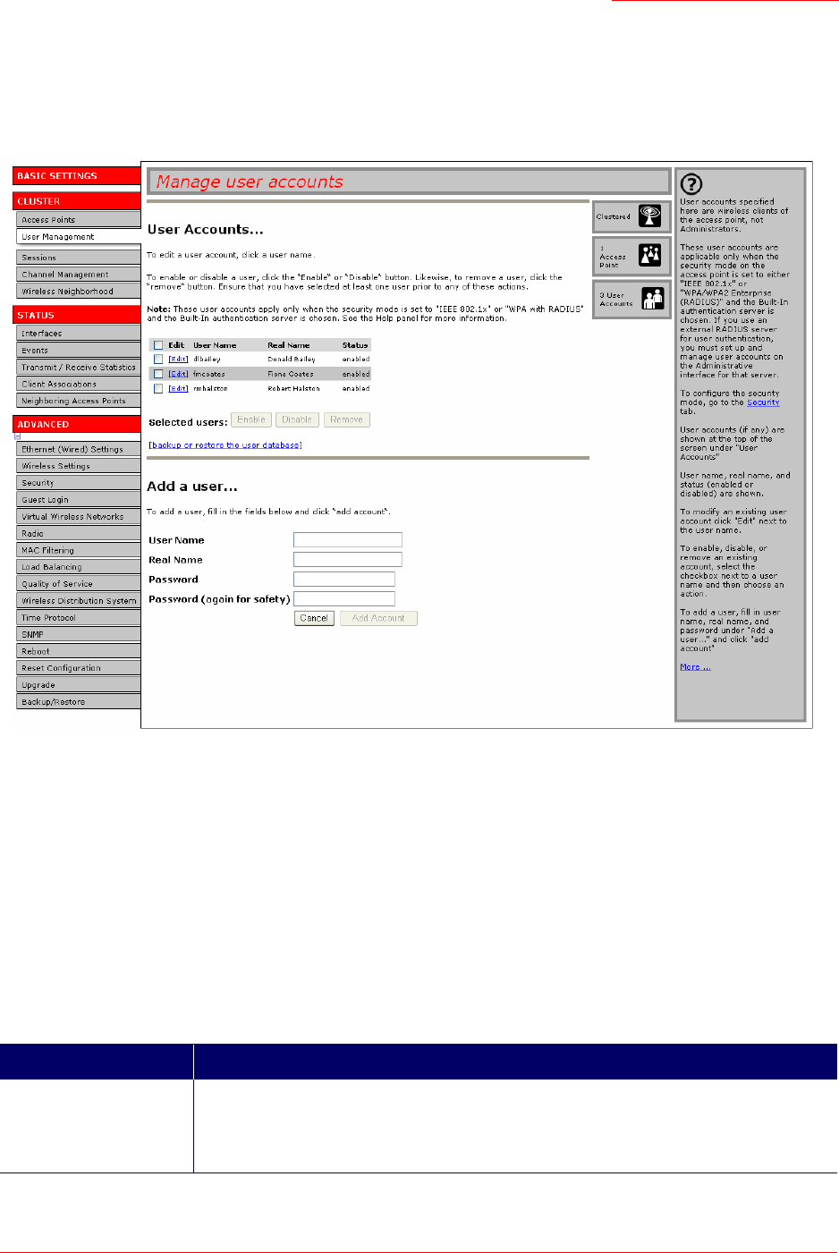
Professional Access Point
Administrator Guide
User Management - 44
Navigating to User Management for Clustered Access Points
To set up or modify user accounts, click the Cluster Menu’s User Management tab.
Viewing User Accounts
User accounts are shown at the top of the screen under User Accounts. User name, real name, and status
(enabled or disabled) are shown.
Adding a User
To create a new user, do the following:
1. Under Add a User, provide information in the following fields.
Field Description
Username Provide a user name.
The user name is an alphanumeric string of up to 237 characters. Do not use special
characters or spaces.
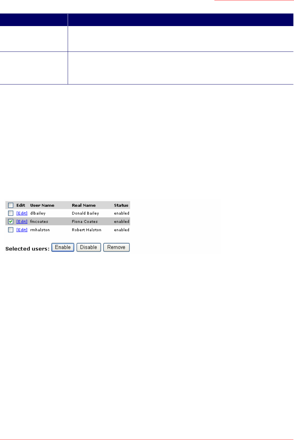
Professional Access Point
Administrator Guide
User Management - 45
2. When you have filled in the fields, click Add Account to add the account.
The new user is then displayed under User Accounts. The user account is enabled by default when you
first create it.
Editing a User Account
Once you have created a user account, it is displayed under User Accounts at the top of the
User Management Administration Web page. To modify an existing user account, first select [Edit] next to
the user name.
Then, make your changes in the Update Account section of the page and click Update Account.
Enabling and Disabling User Accounts
A user account must be enabled for the user to log on and use the access point.
You can enable or disable any user account. With this feature, you can maintain a set of user accounts
and authorize or prevent users from accessing the network without having to remove or re-create
accounts. This ability is useful in situations where users have an occasional need to access the network.
For example, contractors who do work for your company on an intermittent but regular basis might need
network access for 3 months at a time, then be off for 3 months, and back on for another assignment. You
can enable and disable these user accounts as needed, and control access as appropriate.
Enabling a User Account
To enable a user account, select the check box next to the user name and click Enable.
Real Name For information purposes, provide the user’s full name.
Real name is a maximum of 256 characters long.
Password Specify a password for this user.
The password is an alphanumeric string of up to 256 characters. Do not use special
characters or spaces.
Note
A limit of 100 user accounts per access point is imposed by the Web User Interface. Network usage
may impose a more practical limit, depending upon the demand from each user.
Field Description

Professional Access Point
Administrator Guide
User Management - 46
A user with an account that is enabled can log on to the wireless access points in your network.
Disabling a User Account
To disable a user account, select the check box next to the user name and click Disable.
A user with an account that is disabled cannot log on to the wireless access points in your network.
However, the user account remains in the database and can be enabled later as needed.
Removing a User Account
To remove a user account, select the check box next to the user name and click Remove.
If you think that you might need to add this user again at a later date, you might consider disabling the user
account rather than removing it.
Backing Up and Restoring a User Database
You can save a copy of the current set of user accounts to a backup configuration file. The backup file can
be used at a later date to restore the user accounts on the access point to the previous configuration.
Backing Up the User Database
To create a backup copy of the user accounts for the access point:
1. Click the backup or restore the user database link; then click backup user database.
A File Download or Open dialogue box is displayed.
2. Choose the Save option.
A file browser is displayed.
3. Use the file browser to navigate to the directory where you want to save the file, and click OK to save
the file.
You can use the default file name (
wirelessUsers.ubk
) or specify a new file name, but be sure to
save the file with a
.ubk
extension.
Restoring a User Database from a Backup File
To restore a user database from a backup file:
1. Click the backup or restore the user database link; then click restore user database.
2. Select the backup configuration file that you want to use, either by typing the full path and file name in
the Restore field or by clicking Browse and selecting the file.
(Only those files that were created with the User Database Backup function and saved as
.ubk
backup
configuration files are valid to use with Restore; for example,
wirelessUsers.ubk
.)

Professional Access Point
Administrator Guide
User Management - 47
3. Click the Restore button.
When the backup restore process is complete, a message indicates that the user database has been
successfully restored. (This process is not time-consuming; the restore should complete almost imme-
diately.)
Click the Cluster menu’s User Management tab to see the restored user accounts.

Professional Access Point
Administrator Guide
User Management - 48
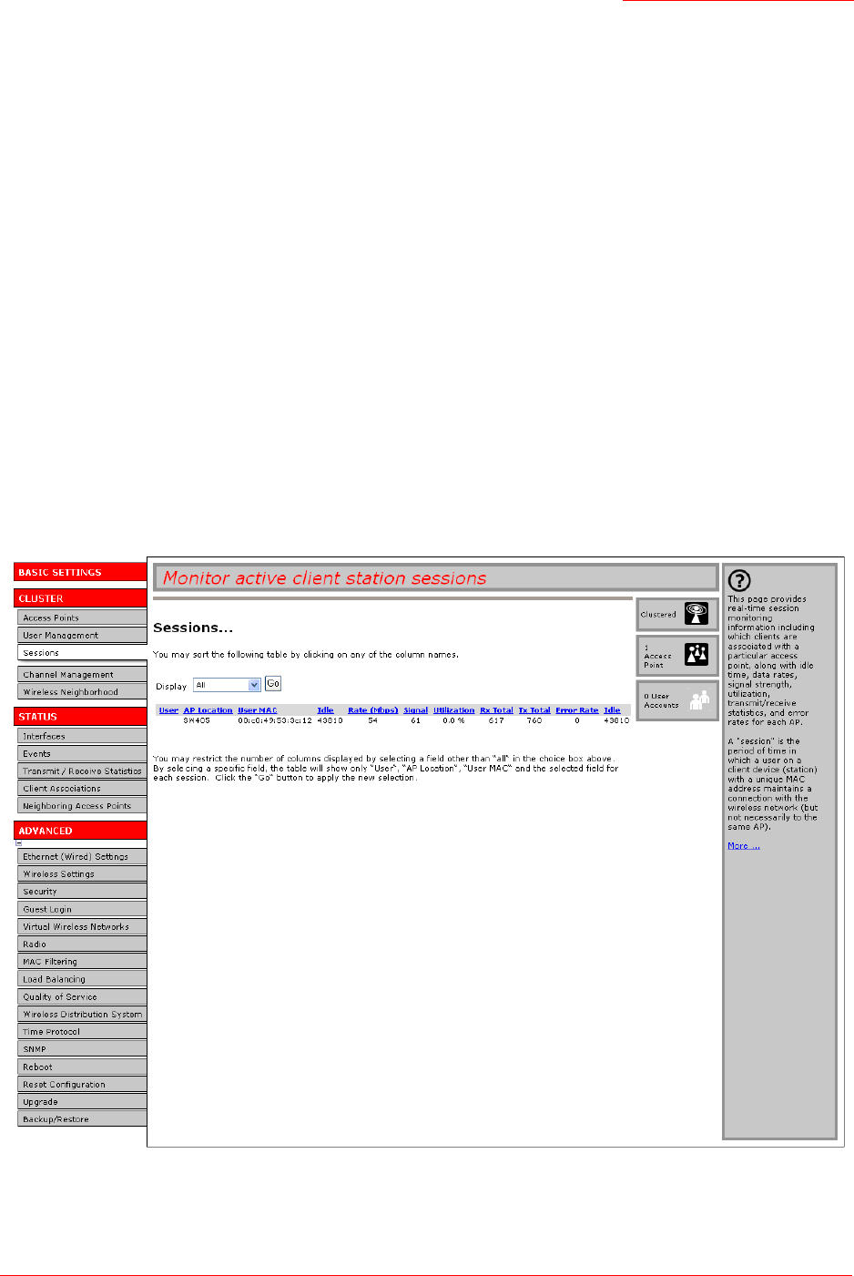
Professional Access Point
Administrator Guide
Sessions - 49
Sessions
The Professional Access Point provides real-time session monitoring information including which users
and clients are associated with a particular access point, data rates, transmit/receive statistics, signal
strength, and idle time.
The following Session Monitoring topics are covered here:
•Navigating to Session Monitoring
•Understanding Session Monitoring Information
•Viewing Session Information for Access Points
•Sorting Session Information
•Refreshing Session Information
Navigating to Session Monitoring
To view session monitoring information, click the Cluster menu’s Sessions tab.

Professional Access Point
Administrator Guide
Sessions - 50
Understanding Session Monitoring Information
The Sessions page shows information about users and client devices associated with access points in the
cluster. Each session is identified by user name and client MAC address, along with the access point
(location) to which the client is connected.
To view a particular statistic for a session, select the item from the Display list and click Go. You can view
Idle Time, Data Rate, Signal, Utilization, and so on; all of which are described in detail in the table below.
A session is the period of time for which a user on a client device with a unique MAC address maintains a
connection with the wireless network. The session begins when the user logs on to the network, and the
session ends when the user either logs off intentionally or loses the connection unintentionally.
Details about session information are given below.
Note
A session is not the same as an association, which describes a client connection to a particular access
point. A client network connection can shift from one clustered access point to another within the con-
text of the same session. A client station can roam between APs and maintain the session.
For information about monitoring associations and link integrity monitoring, see “Client Associations”
on page 73.
Field Description
User The user names of IEEE 802.1x clients.
Note: This field is relevant only for clients that are connected to APs using
IEEE 802.1x security mode and local authentication server. (For more informa-
tion about this mode, see “IEEE 802.1x” on page 104.) For clients of APs using
IEEE 802.1x with RADIUS server or other security modes, no user name will
be shown here.
AP Location The location of the access point.
This is derived from the location description specified on the Basic Settings
tab.
User MAC The MAC address of the user’s client device.
A MAC address is a hardware address that uniquely identifies each node of a
network.
Idle The amount of time that this station has remained inactive.
A station is considered to be idle when it is not receiving or transmitting data.
Idle time is measured in milliseconds.
Rate The speed at which this access point is transferring data to the client.
The data transmission rate is measured in megabits per second (Mbps).
This value will fall within the range of the advertised rate set for the IEEE
802.1x mode in use on the access point. For example, 1 to 54Mbps for
802.11g.

Professional Access Point
Administrator Guide
Sessions - 51
Viewing Session Information for Access Points
You can view session information for all access points on the network at the same time, or you can set the
display to show session information for a specified access point chosen from the list at the top of the page.
To view information on all access points, select Show all access points at the top of the page.
To view session information on a particular access point, select Show only this access point and select the
access point name from the list.
Sorting Session Information
To order (sort) the information in the tables, click on the column label by which you want to order the
information rows. For example, if you want to see the table rows ordered by utilization rate, click on the
Utilization column label. The entries will be sorted by utilization rate.
Refreshing Session Information
You can force an update of the information displayed on the Session Monitoring page by clicking the
Refresh button.
Signal Indicates the strength of the radio frequency (RF) signal the client receives
from the access point.
The measure used for this is an IEEE 802.1x value known as Received Signal
Strength Indication (RSSI), and is a value between 0 and 100.
RSSI is determined by a an IEEE 802.1x mechanism implemented on the net-
work interface card (NIC) of the client.
Utilization Utilization rate for this station.
For example, if the station is active (transmitting and receiving data) 90% of the
time and inactive 10% of the time, its utilization rate is 90%.
Rx Total Receive Total: Indicates number of total packets received by the client during
the current session.
Tx Total Transmit Total: Indicates number of total packets transmitted to the client dur-
ing this session.
Error Rate Indicates the percentage frames that are dropped during transmission on this
access point.
Field Description

Professional Access Point
Administrator Guide
Sessions - 52

Professional Access Point
Administrator Guide
Channel Management - 53
Channel Management
The following Channel Management topics are covered here:
•Navigating to Channel Management
•Understanding Channel Management
•How it Works: Overview
•Overlapping Channels: Background Information
•Example: A Network before and after Channel Management
•Configuring and Viewing Channel Management Settings
•Stopping/Starting Automatic Channel Assignment
•Viewing Current Channel Assignments and Setting Locks
•Viewing Last Proposed Set of Changes
•Configuring Advanced Settings (Customizing and Scheduling Channel Plans)
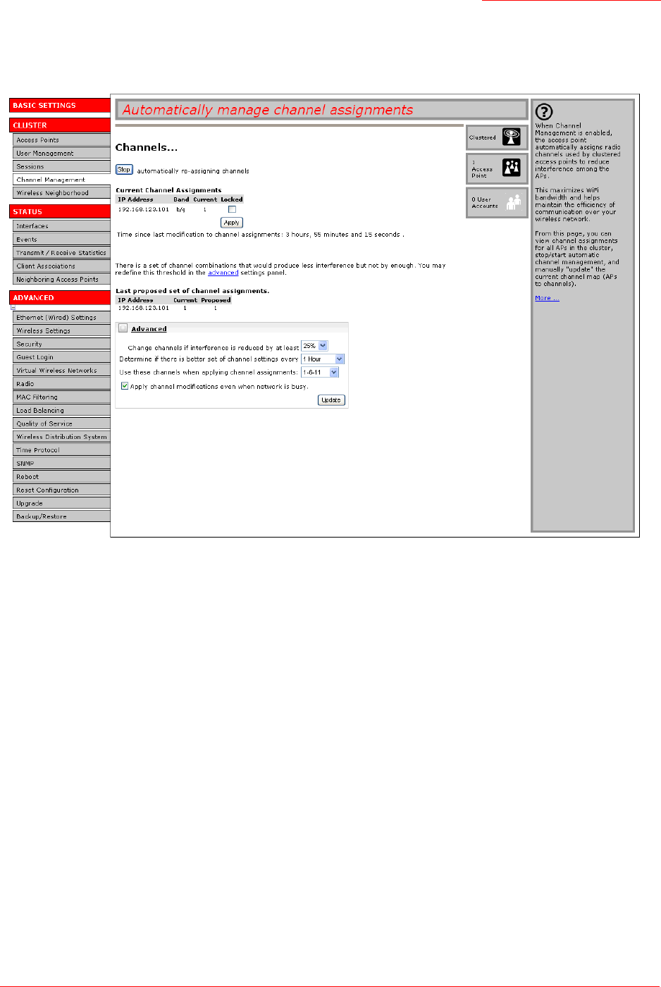
Professional Access Point
Administrator Guide
Channel Management - 54
Navigating to Channel Management
To view session monitoring information, click the Cluster menu’s Channel Management tab.
Understanding Channel Management
When Channel Management is enabled, the Professional Access Point automatically assigns radio
channels used by clustered access points to reduce interference with access points both within and
outside of its cluster. This dynamic channel assignment maximizes Wi-Fi bandwidth and helps maintain
the efficiency of communication over your wireless network.
How it Works: Overview
At a specified interval, or on demand, Channel Management maps APs to channel use and measures
interference levels in the cluster. If significant channel interference is detected, Channel Management
automatically reassigns some or all of the APs to new channels according to an efficiency algorithm (or
automated channel plan).
Overlapping Channels: Background Information
The radio frequency (RF) broadcast Channel defines the portion of the radio spectrum that the radio on the
access point uses for transmitting and receiving. The range of available channels for an access point is
determined by the IEEE 802.11 mode, or band, of the access point. IEEE 802.11b and 802.11g modes
(802.11 b/g) support the use of channels 1 through 11.
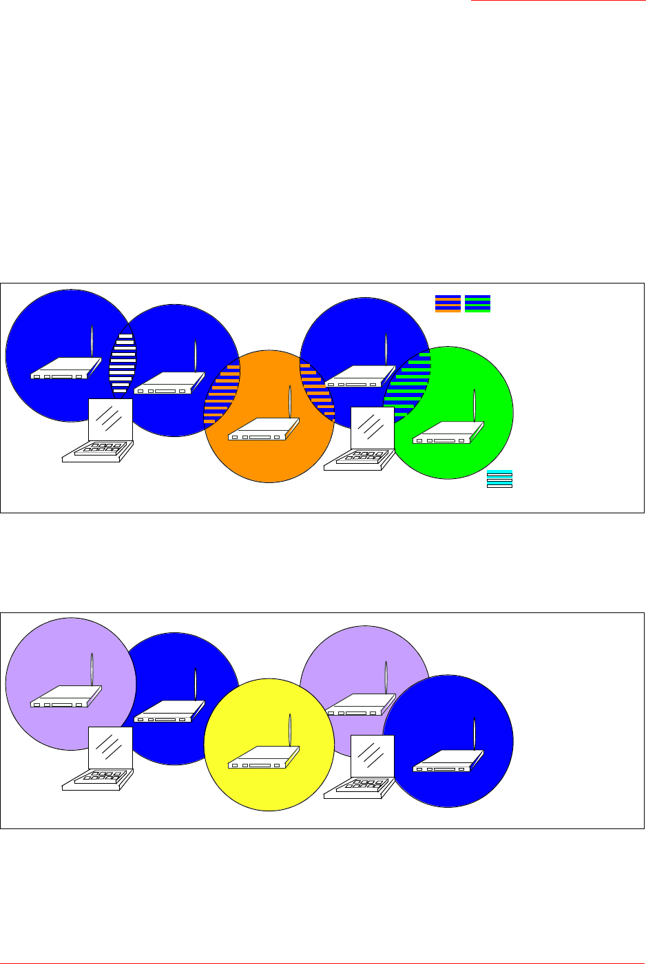
Professional Access Point
Administrator Guide
Channel Management - 55
Interference can occur when multiple access points within range of each other are broadcasting on the
same or overlapping channels. The impact of this interference on network performance can intensify
during busy times when large amounts of data and media traffic compete for bandwidth.
Channel management uses a predetermined set of channels that minimizes interference. For the b/g radio
band, the classic set of non-interfering channels is 1, 6, 11. Channels 1, 4, 8, 11 produce minimal overlap.
Example: A Network before and after Channel Management
Without automated channel management, channel assignments to clustered APs might be made on
consecutive channels, which would overlap and cause interference. For example, AP1 could be assigned
to channel 6, AP2 to channel 6, and AP3 to channel 5 as shown in Figure 3.
Figure 3. Without Automatic Channel Management: APs Can Broadcast on Overlapping Channels.
With automated channel management, APs in the cluster are automatically reassigned to non-interfering
channels as shown in Figure 4.
Figure 4. With Channel Management Enabled: APs are Reassigned to Non-Interfering Channels.
Configuring and Viewing Channel Management Settings
The Channel Management page shows previous, current, and planned channel assignments for clustered
AP3
AP1
Channel 6
(802.11b)
AP2
Channel 6
(802.11b)
Channel 5
(802.11b)
Channel 6
(802.11b)
AP5
Channel 7
(802.11b)
AP4
Client Station Client Station Interference from APs
on same channel (6)
Interference from
APs on adjacent channels
(5,6,7)
AP2
Channel 6
(802.11b)
AP1
Channel 1
(802.11b) Channel 1
(802.11b)
AP4
AP3
Channel 11
(802.11b)
AP5
Channel 6
(802.11b)
Client Station
Client Station

Professional Access Point
Administrator Guide
Channel Management - 56
access points. By default, automatic channel assignment is disabled. You can start channel management
to optimise channel usage across the cluster on a scheduled interval.
From this page, you can view channel assignments for all APs in the cluster, stop and start automatic
channel management, and manually update the current channel map (APs to channels). During a manual
update, channel management will assess channel usage and, if necessary, reassign APs to new channels
to reduce interference based on the current Advanced channel management settings.
By using the Advanced channel management settings you can modify the interference reduction potential
that triggers channel reassignment, change the schedule for automatic updates, and reconfigure the
channel set used for assignments.
The following sections describe how to configure and use channel management on your network:
•Stopping/Starting Automatic Channel Assignment
•Viewing Current Channel Assignments and Setting Locks
•Update Current Channel Assignments Manually
•Viewing Last Proposed Set of Changes
•Configuring Advanced Settings (Customizing and Scheduling Channel Plans)
•Update Advanced Settings
Stopping/Starting Automatic Channel Assignment
By default, automatic channel assignment is disabled (off).
To enable automatic channel assignment,
1. Click Start.
2. Wait 60 seconds.
3. Use your browser control to refresh the Channel Management page.
When automatic channel assignment is enabled, channel management periodically maps radio chan-
nels used by clustered access points and, if necessary, reassigns channels on clustered APs to
reduce interference with either cluster members or APs outside the cluster.
To stop automatic channel assignment, click Stop. No channel usage maps or channel reassignments will
be made. Only manual updates will affect the channel assignment.
Note
Channel Management overrides the default cluster behaviour, which is to synchronize radio chan-
nels of all APs across a cluster. When Channel Management is enabled, the radio Channel is not
synchronized across the cluster to other APs. See the note under Radio Settings in “Settings
Shared in the Cluster Configuration” on page 35.

Professional Access Point
Administrator Guide
Channel Management - 57
Viewing Current Channel Assignments and Setting Locks
The Current Channel Assignments show a list of all access points in the cluster by IP Address. The display
shows the band on which each access point is broadcasting, the channel currently used by each access
point, and an option to lock an access point on its current radio channel so that it cannot be reassigned to
another. Details about Current Channel Assignments are provided below.
Update Current Channel Assignments Manually
You can run a manual channel management update at any time by clicking Update under the Current
Channel Assignments display.
Viewing Last Proposed Set of Changes
The Last Proposed Set of Channel Assignments shows the last channel plan. The plan lists all access points in
the cluster by IP Address and shows the current and proposed channels for each access point. Locked
channels will not be reassigned, and the optimization of channel distribution among APs will take into
account the fact that locked APs must remain on their current channels. APs that are not locked may be
assigned to different channels than they were previously using, depending on the results of the plan.
Configuring Advanced Settings (Customizing and Scheduling Channel Plans)
If you use channel management without updating Advanced settings, channels are automatically fine-
tuned once every hour if interference can be reduced by 25 percent or more. Channels will be reassigned
even if the network is busy. These defaults are designed to satisfy most situations in which you would need
Field Description
IP Address Specifies the IP Address for the access point.
Band Indicates the band on which the access point is broadcasting.
Current Indicates the radio Channel on which this access point is currently
broadcasting.
Locked Select Locked if you want to this access point to remain on the current
channel.
When an access point’s channel is locked, automated channel management
plans will not reassign the access point to a different channel as a part of the
optimization strategy. Instead, APs with locked channels will be factored in as
requirements for the plan.
If you click Apply, you will see that locked APs show the same channel for
Current Channel and Proposed Channel. Locked APs keep their current channels.
Field Description
IP Address Specifies the IP Address for the access point.
Current Indicates the radio channel on which this access point is currently
broadcasting.
Proposed Indicates the radio channel to which this access point would be reassigned if
the Channel Plan is executed.

Professional Access Point
Administrator Guide
Channel Management - 58
to implement channel management.
You can use Advanced settings to modify the interference reduction potential that triggers channel
reassignment, change the schedule for automatic updates, and reconfigure the channel set used for
assignments
Field Description
Advanced Click Advanced to show or hide display settings that modify
timing and details of the channel planning algorithm.
By default, advanced settings are hidden.
Change channels if interference is reduced by at least Specify the minimum percentage of interference reduction a
proposed plan must achieve in order to be applied. The
default is 25 percent.
Use the list to select percentages ranging from 5 percent to
75 percent.
This setting lets you set a gating factor for channel
reassignment so that the network is not continually disrupted
for minimal gains in efficiency.
For example, if channel interference must be reduced by 75
percent and the proposed channel assignments will only
reduce interference by 30 percent, then channels will not be
reassigned. However; if you reset the minimal channel
interference benefit to 25 percent and click Update, the
proposed channel plan will be implemented and channels
reassigned as needed.
Determine if there is better set of channels every Specify the schedule for automated updates.
A range of intervals is provided, from 1 minute to 6 months
The default is 1 hour (channel usage assessed and the
resulting channel plan applied every hour).
Use these channels when applying channel assignments Choose a set of non-interfering channels. The choices are:
• b/g channels 1-6-11
• b/g channels 1-4-8-11
IEEE 802.11b and 802.11g modes support use of channels 1
through 11. For b and g radio bands, the classic set of non-
interfering channels is 1, 6, and 11. Channels 1, 4, 8, and 11
produce minimal overlap.

Professional Access Point
Administrator Guide
Channel Management - 59
Update Advanced Settings
Click Update under Advanced settings to apply these settings.
Advanced settings take affect when they are applied, and they influence how automatic channel
management is performed. The new interference reduction minimum, scheduled tuning interval, channel
set, and network busy settings will be taken into account for automated and manual updates.
Apply channel modifications even when the network is
busy
Click to enable or disable this setting.
If you enable this setting, channel modifications will be
applied even when the network is busy.
If you disable this setting, channel modifications will not be
applied on a busy network.
This setting, along with the interference reduction setting, is
designed to help weigh the cost/benefit impact on network
performance of reassigning channels against the inherent
disruption it can cause to clients during a busy time.
Field Description

Professional Access Point
Administrator Guide
Channel Management - 60

Professional Access Point
Administrator Guide
Wireless Neighborhood - 61
Wireless Neighborhood
The Wireless Neighborhood view shows those access points within range of any access point in the
cluster. This page provides a detailed view of neighbouring access points including identifying information
such as SSIDs and MAC addresses for each, cluster status, and statistical information such as the
broadcast channel and signal strength of each AP.
The following topics are covered here:
•Navigating to Wireless Neighborhood
•Understanding Wireless Neighbourhood Information
•Viewing Wireless Neighborhood
•Viewing Details for a Cluster Member
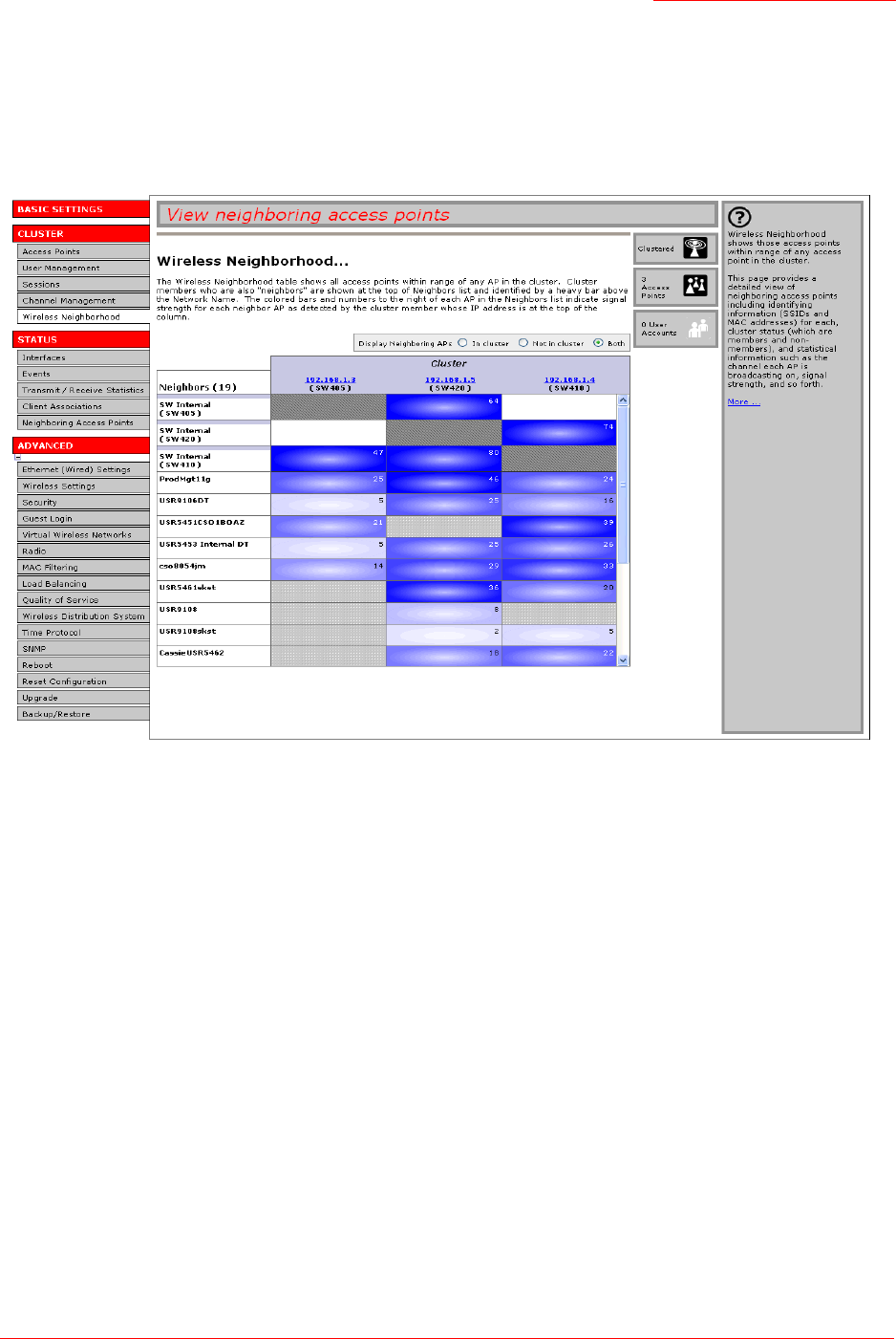
Professional Access Point
Administrator Guide
Wireless Neighborhood - 62
Navigating to Wireless Neighborhood
To view the Wireless Neighborhood, click the Cluster menu’s Wireless Neighborhood tab.
Figure 5. Neighbour APs Both in Cluster and Not in Cluster.
Understanding Wireless Neighbourhood Information
The Wireless Neighborhood view shows all access points within range of every member of the cluster,
shows which access points are within range of which cluster members, and distinguishes between cluster
members and non-members.
For each neighbour access point, the Wireless Neighborhood view shows identifying information (SSID or
Network Name, IP Address, MAC address) along with radio statistics (signal strength, channel, beacon
interval). You can click on an access point’s IP address to get additional statistics about the APs within
radio range of the currently selected AP.
The Wireless Neighborhood view can help you:
• Detect and locate unexpected (or rogue) access points in a wireless domain so that you can take
action to limit associated risks.
• Verify coverage expectations. By assessing which APs are visible at what signal strength from other
APs, you can verify that the deployment meets your planning goals.

Professional Access Point
Administrator Guide
Wireless Neighborhood - 63
• Detect faults. Unexpected changes in the coverage pattern are evident at a glance in the colour coded
table.
Viewing Wireless Neighborhood
Details about Wireless Neighborhood information shown is described below.
Field Description
Display neighboring APs Click one of the following radio buttons to change the view:
•In cluster - Shows only neighbour APs that are members of the cluster
•Not in cluster - Shows only neighbour APs that are not cluster members
•Both - Shows all neighbour APs (cluster members and non-members)
Cluster The Cluster list at the top of the table shows IP addresses for all access points
in the cluster. This is the same list of cluster members shown on the Cluster
menu’s Access Points tab described in “Navigating to Access Points
Management” on page 34.
If there is only one AP in the cluster, only a single IP address column will be
displayed here; indicating that the AP is clustered with itself.
You can click an IP address to view more details for a particular AP as shown
in Figure 6 below.
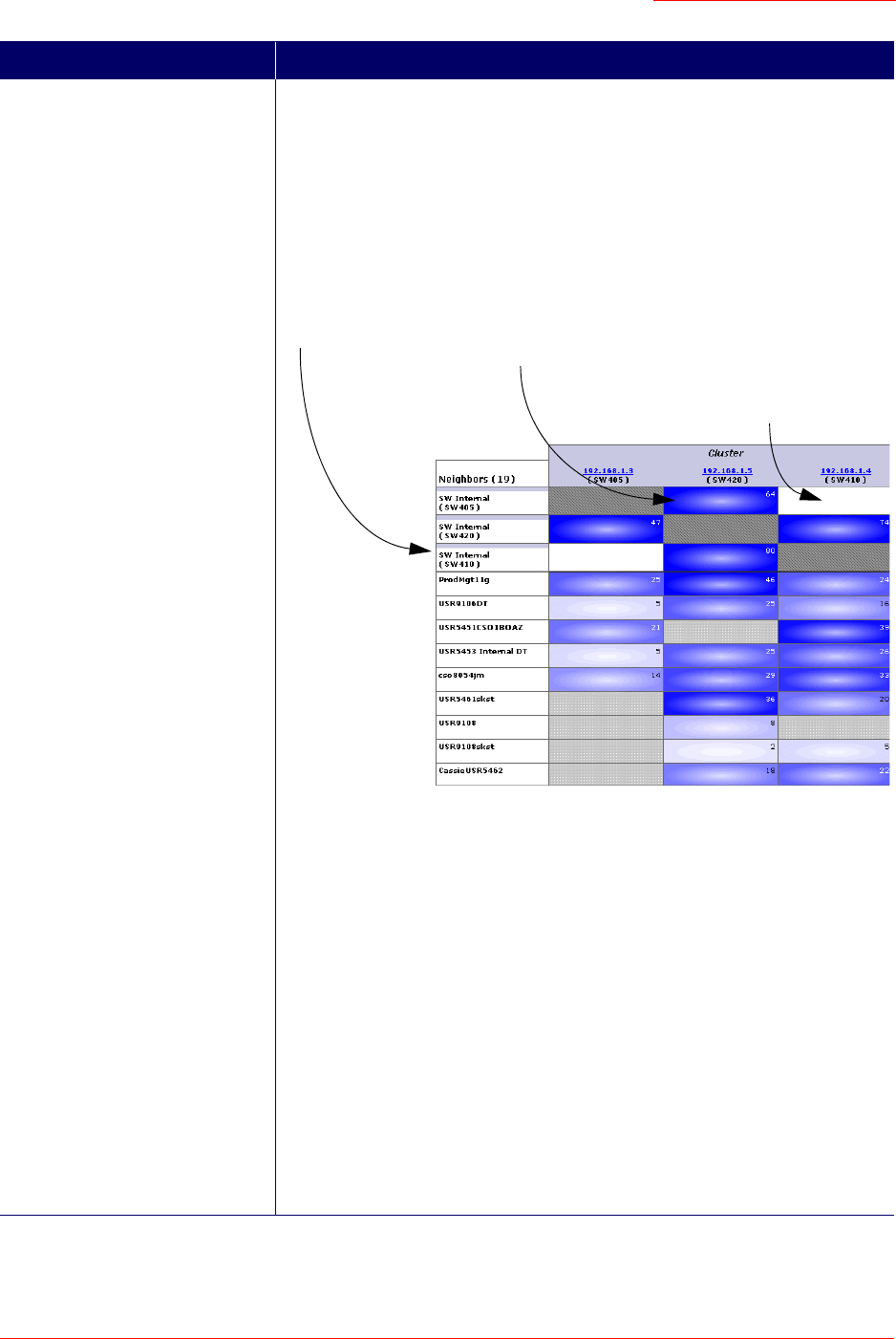
Professional Access Point
Administrator Guide
Wireless Neighborhood - 64
Neighbors Access points that are neighbours of one or more of the clustered APs are
listed in the left column by SSID (Network Name).
An access point which is detected as a neighbour of a cluster member can also
be a cluster member itself. Neighbours who are also cluster members are
always shown at the top of the list with a heavy bar above the name and
include a location indicator.
The coloured bars to the right of each AP in the Neighbors list shows the signal
strength for each of the neighbour APs as detected by the cluster member
whose IP address is shown at the top of the column:
•Dark Blue Bar - A dark blue bar and a high signal strength number (for
example 50) indicates good signal strength from the neighbour as seen by
the AP whose IP address is shown at the top of the column.
•Lighter Blue Bar - A lighter blue bar and a lower signal strength number (for
example 20 or lower) indicates medium or weak signal strength from the
neighbour as seen by the AP whose IP address is shown at the top of the
column.
•White Bar - A white bar and the number 0 indicates that a neighbouring AP
that was detected by one of the cluster members cannot be detected by the
AP whose IP address is shown at the top of the column.
•Light Gray Bar - A light gray bar and no signal strength number indicates a
neighbour that is detected by other cluster members but not by the AP
whose IP address is shown at the top of the column.
•Dark Gray Bar - A dark gray bar and no signal strength number indicates
this is the AP whose IP address is shown at the top of the column.
Field Description
This access point is a cluster member and can be seen by the AP
whose IP address is 192.168.1.5 at a signal strength of 64...
... but it cannot be seen by the access
point whose address is 192.168.1.4.
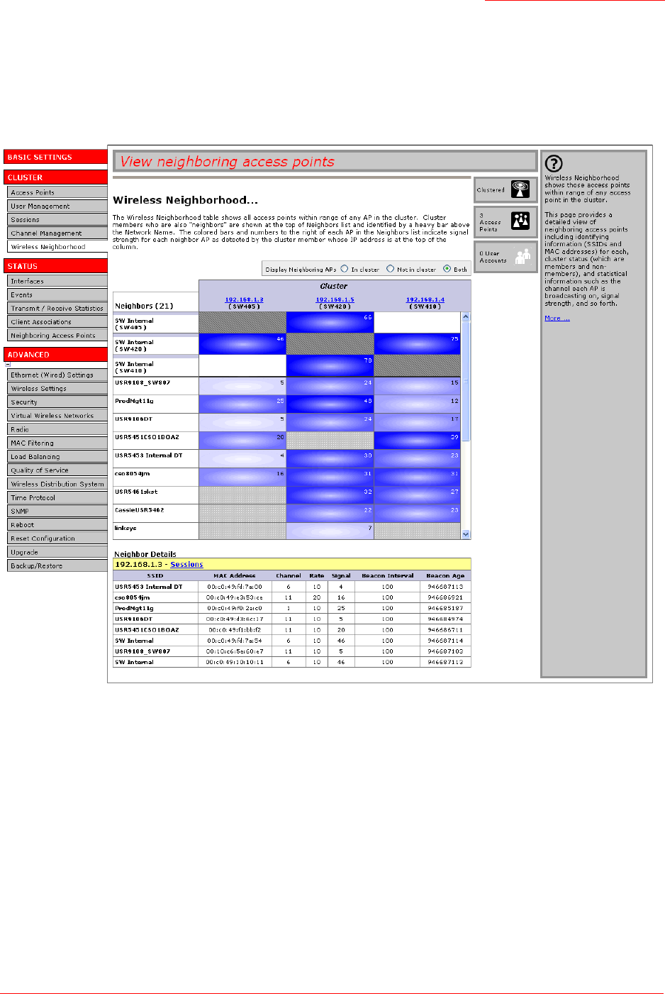
Professional Access Point
Administrator Guide
Wireless Neighborhood - 65
Viewing Details for a Cluster Member
To view details on a cluster member AP, click the IP address of a cluster member at the top of the table.
Figure 6. Details for a Cluster Member AP.

Professional Access Point
Administrator Guide
Wireless Neighborhood - 66
The following table explains the details shown about the selected AP.
Field Description
SSID Shows the Service Set Identifier (SSID) for the access point.
The SSID is an alphanumeric string of up to 32 characters that uniquely identi-
fies a wireless local area network. It is also referred to as the Network Name.
The SSID is set in Basic Settings. (See “Basic Settings” on page 25) or on
Advanced menu’s Wireless Settings page (see “Wireless Settings” on
page 87.)
A Guest network and an Internal network running on the same access point
must always have two different network names.
MAC Address Shows the MAC address of the neighbouring access point.
A MAC address is a hardware address that uniquely identifies each node of a
network.
Channel Shows the channel on which the access point is currently broadcasting.
The Channel defines the portion of the radio spectrum that the radio uses for
transmitting and receiving.
The channel is set on the Advanced menu’s Radio Settings page. (See “Radio”
on page 119.)
Rate Shows the rate (in megabits per second) at which this access point is currently
transmitting.
The current rate will always be one of the rates shown in Supported Rates.
Signal Indicates the strength of the radio signal emitting from this access point as
measured in decibels (Db).
Beacon Interval Shows the Beacon interval being used by this access point.
Beacon frames are transmitted by an access point at regular intervals to
announce the existence of the wireless network. The default behaviour is to
send a beacon frame once every 100 milliseconds (or 10 per second).
The beacon Interval is set on the Advanced menu’s Radio Settings page. (See
“Radio” on page 119.)
Beacon Age Shows the date and time of the most recent beacon transmission from the
access point.

Professional Access Point
Administrator Guide
Interfaces - 67
Status
You can view information about an individual access point from the Status menu. Because the Status
pages display settings for a specific access point—not for a cluster configuration that is automatically
shared by multiple access points—it is important to ensure that you are accessing the Web User Interface
for the access point that you want to monitor (see “Navigating to the Web User Interface for a Specific
Access Point” on page 40.)
You can use the Status pages to monitor the following aspects of an access point:
•Interfaces
•Events
•Transmit/Receive Statistics
•Client Associations
•Neighboring Access Points
Interfaces
To monitor wired LAN and wireless LAN (WLAN) settings, navigate to the Status menu’s Interfaces tab on
the Web User Interface for the access point that you want to monitor.
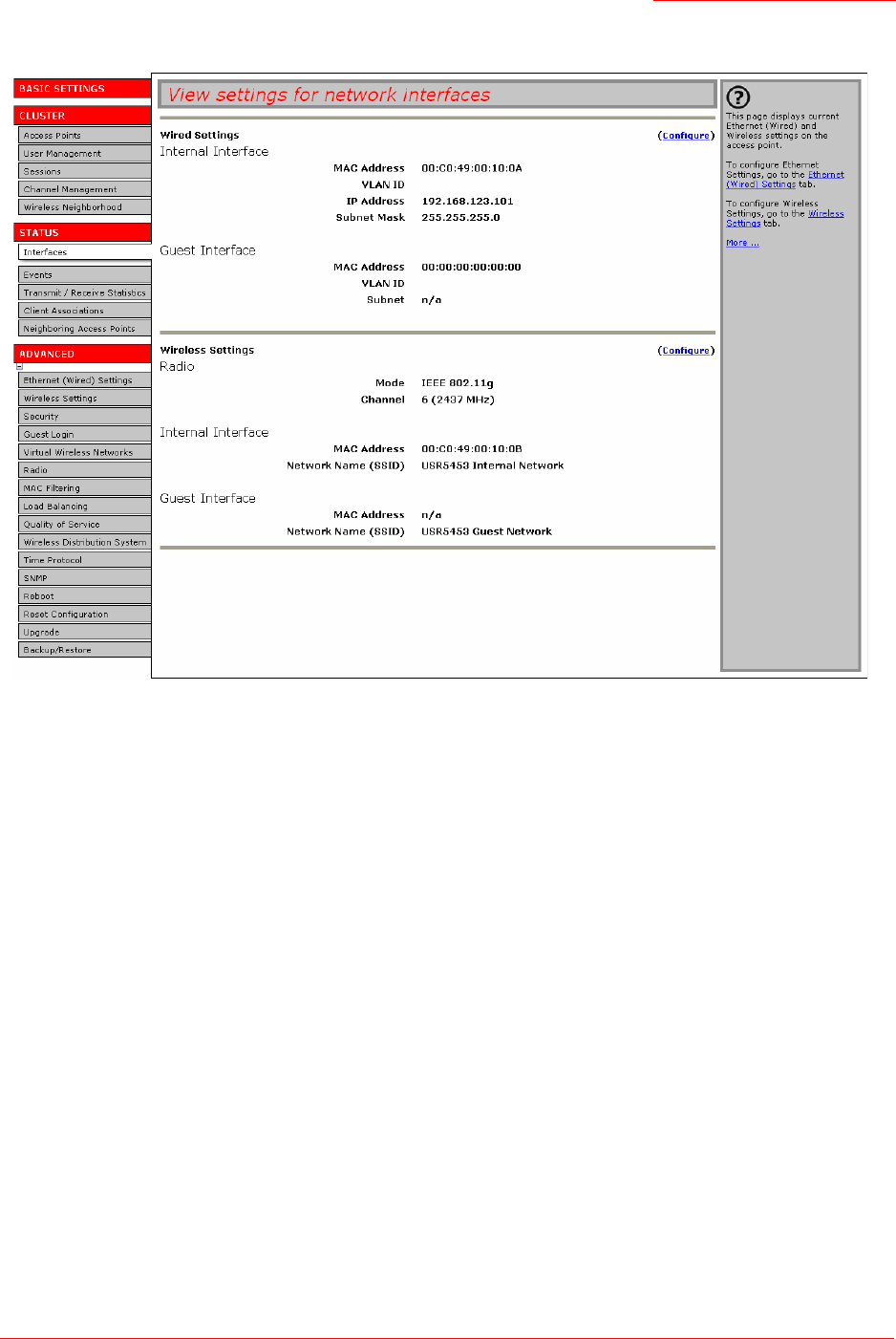
Professional Access Point
Administrator Guide
Interfaces - 68
This page displays the current Ethernet (Wired) Settings and Wireless Settings.
Ethernet (Wired) Settings
The Internal interface includes the Ethernet MAC Address, VLAN ID, IP Address, and Subnet Mask.
The Guest interface includes the MAC Address, VLAN ID, and Subnet.
If you want to change any of these settings, click the Configure link.
Wireless Settings
The Radio Interface settings include radio Mode and Channel. Also shown here are MAC addresses and
network names for internal and guest interfaces. (See “Wireless Settings” on page 87 and “Radio” on
page 119 for more information.)
If you want to change any of these settings, click the Configure link.
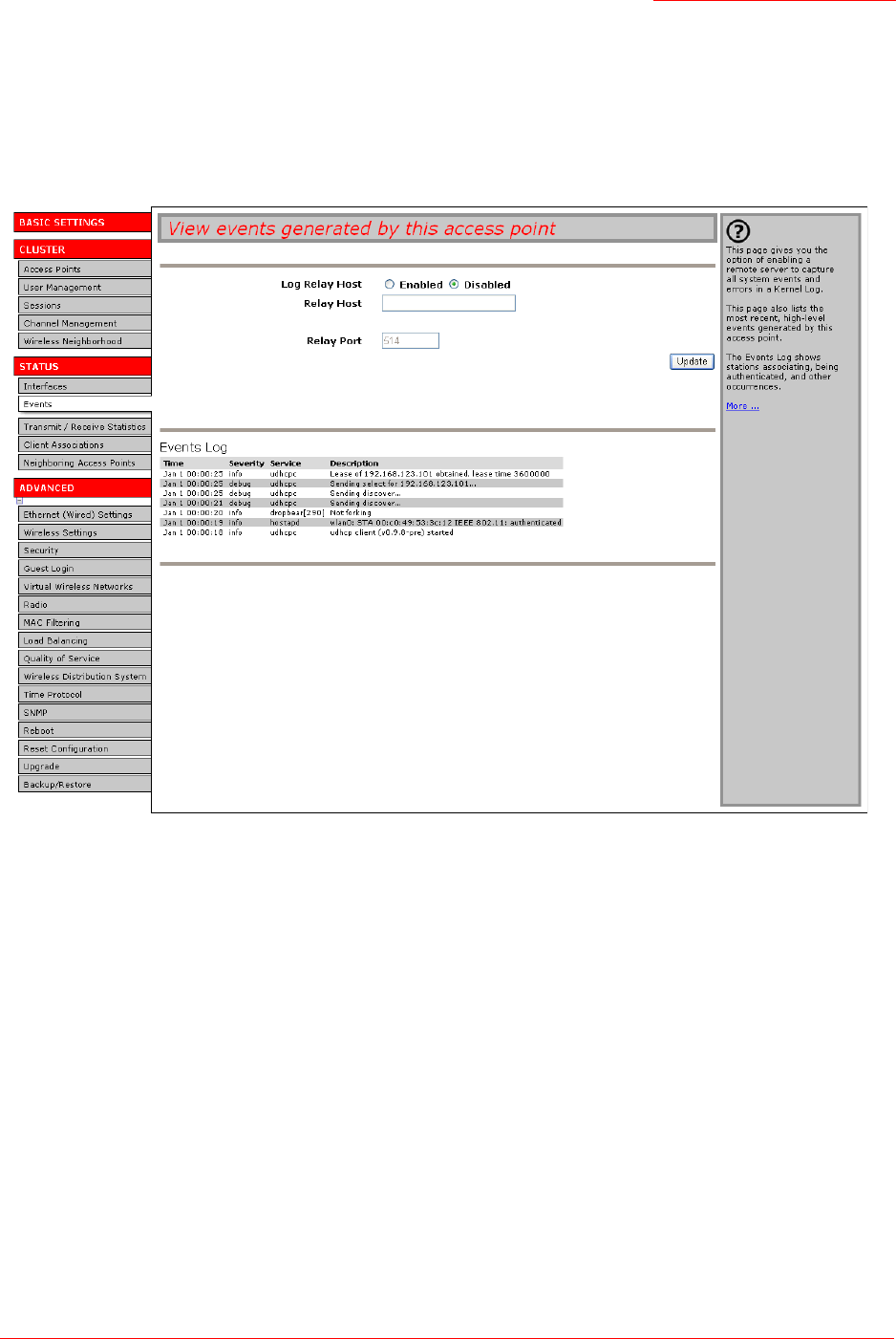
Professional Access Point
Administrator Guide
Events - 69
Events
To view system events and kernel log for a particular access point, navigate to the Status menu’s Events
tab on the Web User Interface for the access point that you want to monitor
.
This page lists the most recent events generated by this access point (see “Events Log” on page 72).
This page also gives you the option of enabling a remote log relay host to capture all system events and
errors in a Kernel Log. (This requires setting up a remote relay host first. See “Log Relay Host for Kernel
Messages” on page 69).
Log Relay Host for Kernel Messages
•Understanding Remote Logging
•Setting Up the Log Relay Host
Note
The Professional Access Point acquires its date and time information using the network time protocol
(NTP). This data is reported in UTC format (also known as Greenwich Mean Time). You need to con-
vert the reported time to your local time.
For information on setting the network time protocol, see “Time Protocol” on page 151.

Professional Access Point
Administrator Guide
Events - 70
•Enabling and Disabling the Log Relay Host on the Status Menu’s Events Page
Understanding Remote Logging
The kernel log is a comprehensive list of system events (shown in the System Log) and kernel messages,
such as an error message for dropping frames.
You cannot view kernel log messages directly from the Web User Interface for an access point. You must
first set up a remote server running a syslog process and acting as a system log relay host on your
network. Then, you can configure the Professional Access Point to send its system log messages to the
remote server.
Using a remote server to collect access point system log messages affords you several benefits. You can:
• Aggregate system log messages from multiple access points
• Store a longer history of messages than kept on a single access point
• Trigger scripted management operations and alerts
Setting Up the Log Relay Host
To use kernel log relaying, you must configure a remote server to receive the syslog messages. This
procedure will vary depending on the type of machine you use as the remote log host. Following is an
example of how to configure a remote Linux server using the syslog daemon.
Example of Using Linux syslogd
The following steps activate the syslog daemon on a Linux server. Make sure that you have
root
user
identity for these tasks.
1. Log on as
root
to the machine that you want to use as your syslog relay host.
The following operations require
root
user permissions. If you are not already logged on as
root
, type
su
at the command line prompt to become
root
("super user").
2. Edit
/etc/init.d/sysklogd
and add "
-r
" to the variable
SYSLOGD
near the top of the file. The line that
you edit will look like this:
SYSLOGD="-r"
Consult the man pages to get more information on
syslogd
command options. (Type
man syslogd
at
the command line.)
3. If you want to send all the messages to a file, edit
/etc/syslog.conf
.
For example you can add this line to send all messages to a log file called
AP_syslog
:
*.* -/tmp/AP_syslog
Consult the
man
pages to get more information on
syslog.conf
command options. (Type
man
syslog.conf
at the command line.)
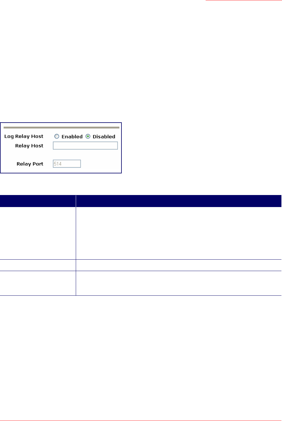
Professional Access Point
Administrator Guide
Events - 71
4. Restart the syslog server by typing the following at the command line prompt:
/etc/init.d/sysklogd restart
Enabling and Disabling the Log Relay Host on the Status Menu’s Events Page
To enable and configure log relaying on the Status menu’s Events page, set the log relay options as
described below.
Update Settings
To apply your changes, click Update.
If you enabled the log relay host, clicking Update will activate remote logging. The access point will send its
kernel messages real-time for display to the remote log server monitor, a specified kernel log file, or other
storage, depending on how you configured the log relay host.
If you disabled the log relay host, clicking Update will disable remote logging.
Note
The syslog process will default to use port 514. USRobotics recommends using this default port.
However, if you choose to reconfigure the log port, make sure that the port number that you assign to
syslog is not being used by another process.
Field Description
Log Relay Host Enabled Choose to either enable or disable use of the Log Relay Host:
• Enabled
• Disabled
If you select Enabled, the Relay Host and Relay Port fields are editable.
Relay Host Specify the IP Address or DNS name of the relay host.
Relay Port Specify the port number for the syslog process on the relay host.
The default port is 514.
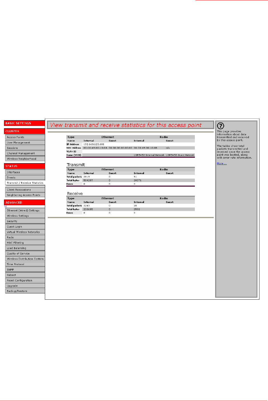
Professional Access Point
Administrator Guide
Transmit/Receive Statistics - 72
Events Log
The Events Log shows system events on the access point such as stations associating or being
authenticated. The real-time Events Log is always shown on the Status menu’s Events page for the access
point you are monitoring.
Transmit/Receive Statistics
To view transmit/receive statistics for a particular access point, navigate to the Status menu’s Transmit/
Receive Statistics on the Web User Interface for the access point that you want to monitor.

Professional Access Point
Administrator Guide
Client Associations - 73
This page provides basic information about the current access point and a real-time display of the transmit
and receive statistics for this access point as described in the table below. All transmit and receive
statistics shown are totals accumulated since the access point was last started. If the access point is
rebooted, these figures indicate transmit/receive totals since the reboot.
Client Associations
To view the client stations associated with a particular access point, navigate to the
Status menu’s Client Associations on the Web User Interface for the access point that you want to monitor.
Field Description
IP Address IP Address for the access point.
MAC Address Media Access Control (MAC) address for the specified interface.
The Professional Access Point has a unique MAC address for each interface.
VLAN ID Virtual LAN (VLAN) ID.
A VLAN is a software-based, logical grouping of devices on a network that
allow them to act as if they are connected to a single physical network, even
though they may not be.
VLANs can be used to establish internal and guest networks on the same
access point.
Name (SSID) Wireless network name. Also known as the SSID, this alphanumeric key
uniquely identifies a wireless local area network.
The SSID is set on the Basic Settings tab. (See “Provide Administrator Pass-
word and Wireless Network Name” on page 28.)
Transmit and Receive Information
Total Packets The total count of packets sent (in the Transmit table) or received (in the
Received table) by this access point.
Total Bytes The total count of bytes sent (in the Transmit table) or received (in the Received
table) by this access point.
Errors The total count of errors related to sending and receiving data on this access
point.
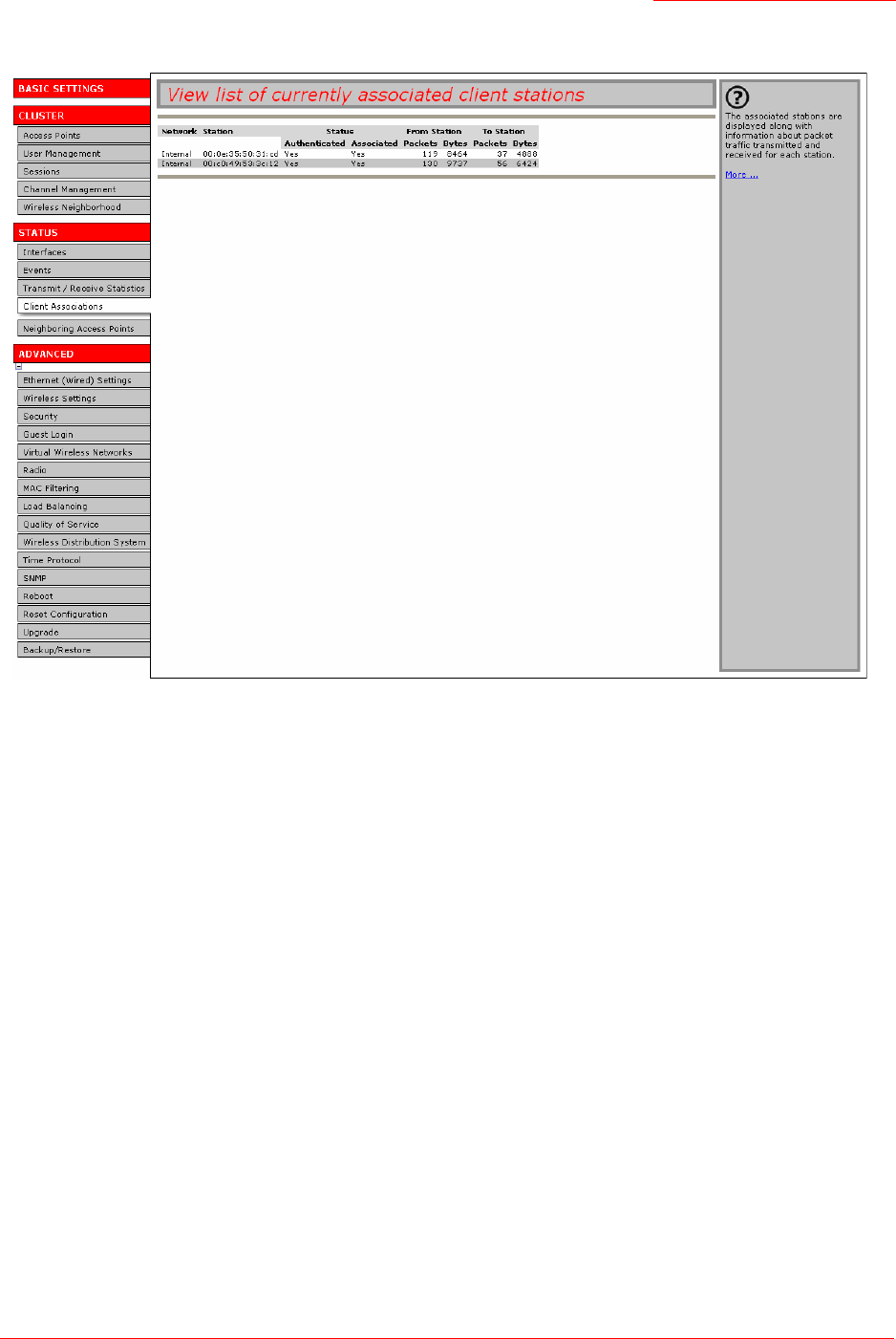
Professional Access Point
Administrator Guide
Client Associations - 74
The associated stations are displayed along with information about packet traffic transmitted and received
for each station.
Link Integrity Monitoring
The Professional Access Point provides link integrity monitoring to continually verify the access point’s
connection to each associated client, even when no data exchange is occurring. To perform this
verification, the access point sends data packets to clients every few seconds when no other traffic is
passing. This allows the access point to detect a client’s having gone out of range, even during periods
when no normal traffic is exchanged.The client connection is dropped from the list of associated clients
within 300 seconds of the client disappearing, even if the client does not disassociate (but went out of
range).
What is the Difference Between an Association and a Session?
An association describes a client’s connection to a particular access point. A session describes a client’s
connection to the network. A client’s network connection can shift from one clustered access point to
another within the context of the same session. A client station can roam between APs and maintain the
session.
For information on monitoring sessions, see “Understanding Session Monitoring Information” on page 50.
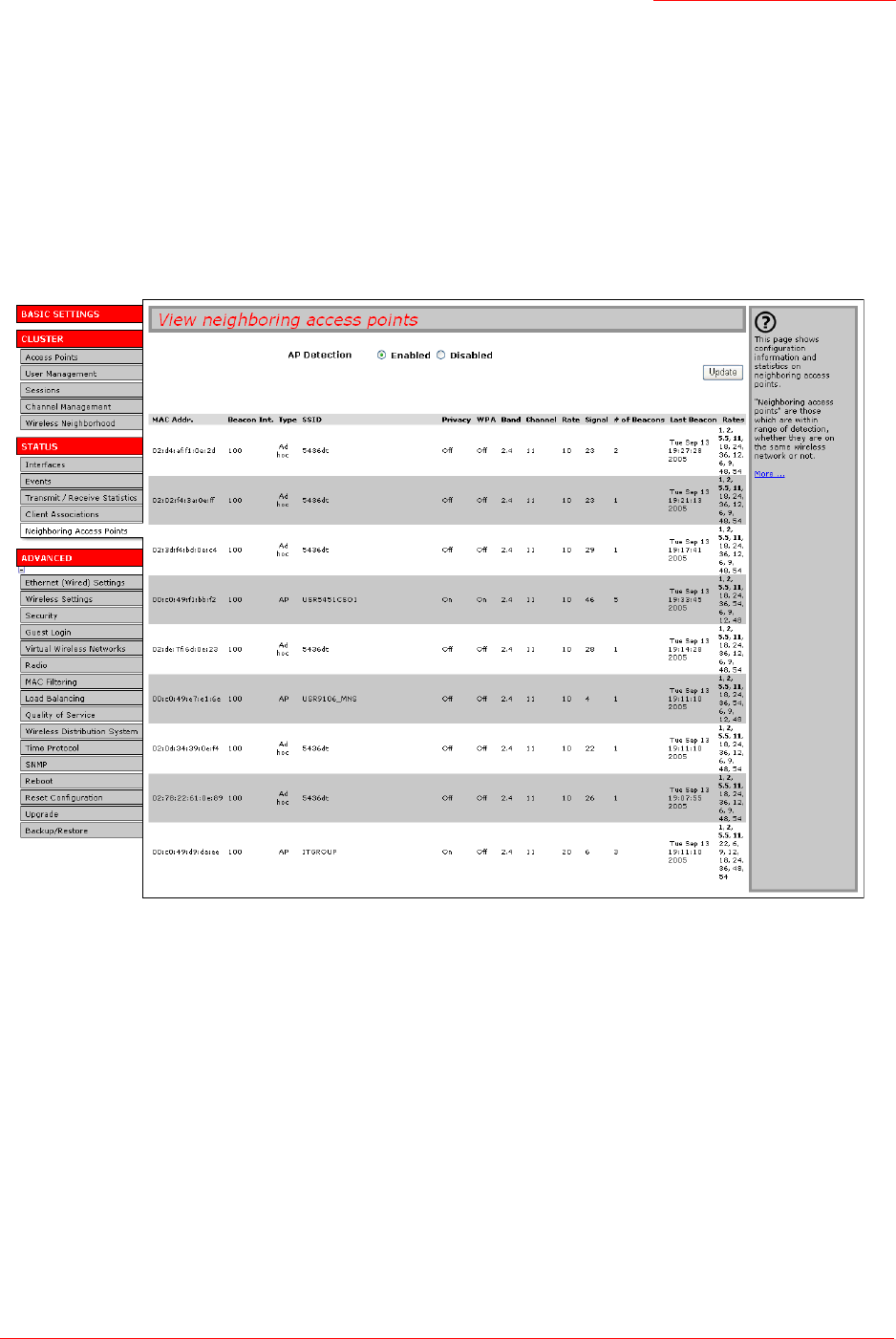
Professional Access Point
Administrator Guide
Neighboring Access Points - 75
Neighboring Access Points
The status page for neighbouring access points provides real-time statistics for all access points within
range of the access point on which you are viewing the Web User Interface.
To view information about other access points on the wireless network,
1. Navigate to the Status menu’s Neighboring Access Points tab.
.
2. Select AP Detection Enabled.
3. Click Update.

Professional Access Point
Administrator Guide
Neighboring Access Points - 76
Information provided for neighbouring access points is described in the following table:
Field Description
MAC Address Shows the MAC address of the neighbouring access point.
A MAC address is a hardware address that uniquely identifies each node of a
network.
Beacon Int. Shows the Beacon interval being used by this access point.
Beacon frames are transmitted by an access point at regular intervals to
announce the existence of the wireless network. The default behaviour is to
send a beacon frame once every 100 milliseconds (or 10 per second).
The Beacon Interval is set on Advanced menu’s Radio Settings page. (See
“Radio” on page 119.)
Type Indicates the type of device:
•AP indicates the neighbouring device is an access point that supports the
IEEE 802.11 Wireless Networking Framework in Infrastructure Mode.
•Ad hoc indicates a neighbouring station running in Ad-hoc Mode. Stations set
to ad-hoc mode communicate with each other directly, without the use of a
traditional access point. Ad-hoc mode is an IEEE 802.11 Wireless Network-
ing Framework also referred to as peer-to-peer mode or an Independent
Basic Service Set (IBSS).
SSID The Service Set Identifier (SSID) for the access point.
The SSID is an alphanumeric string of up to 32 characters that uniquely identi-
fies a wireless local area network. It is also referred to as the Network Name.
The SSID is set in Basic Settings (see “Basic Settings” on page 25) or on the
Advanced menu’s Wireless Settings page (see “Wireless Settings” on
page 87).
A Guest network and an Internal network running on the same access point
must always have two different network names.
Privacy Indicates whether there is any security on the neighbouring device.
•Off indicates that the Security mode on the neighbouring device is set to
None (no security).
•On indicates that the neighbouring device has security in place.
Access point security is configured on the Advanced menu’s Security page.
For more information on security settings, see “Security” on page 91.
WPA Indicates whether WPA security is on or off for this access point.
Band Indicates the IEEE 802.11 mode being used on this access point (IEEE
802.11b or IEEE 802.11g).

Professional Access Point
Administrator Guide
Neighboring Access Points - 77
Channel Shows the channel on which the access point is currently broadcasting.
The Channel defines the portion of the radio spectrum that the radio uses for
transmitting and receiving.
The channel is set on the Advanced menu’s Radio Settings page. (See “Radio”
on page 119.)
Rate Shows the rate (in megabits per second) at which this access point is currently
transmitting.
The current rate will always be one of the rates shown in supported Rates.
Signal Indicates the strength of the radio signal emitting from this access point as
measured in decibels (Db).
# of Beacons Shows the total number of beacons transmitted by this access point since the
access point was last booted.
Last Beacon Shows the date and time of the most recent beacon transmission from the
access point.
Rates Shows supported and basic (advertised) rate sets for the neighbouring access
point. Rates are shown in megabits per second (Mbps).
All supported rates are listed, with basic rates shown in bold.
Rate sets are configured on the Advanced menu’s Radio Settings page. (See
“Radio” on page 119.) The rates shown for an access point will always be the
rates currently specified for that access point in its radio settings.
Field Description

Professional Access Point
Administrator Guide
Neighboring Access Points - 78

Professional Access Point
Administrator Guide
Ethernet (Wired) Settings - 79
Advanced
Advanced Settings include the following:
•“Ethernet (Wired) Settings” on page 79
•“Wireless Settings” on page 87
•“Security” on page 91
•“Guest Login” on page 111
•“Virtual Wireless Networks” on page 115
•“Radio” on page 119
•“MAC Filtering” on page 125
•“Load Balancing” on page 129
•“Quality of Service” on page 133
•“Wireless Distribution System” on page 143
•“Time Protocol” on page 151
•“SNMP” on page 155
•“Reboot” on page 159
•“Reset Configuration” on page 159
•“Upgrade” on page 160
•“Backup/Restore” on page 162
Ethernet (Wired) Settings
Ethernet (Wired) Settings describe the configuration of your Ethernet local area network (LAN).
The following sections describe how to configure the wired address and related settings on the
Professional Access Point:
Note
The Ethernet settings, including guest access, are not shared across the cluster. These settings must
be configured individually on the Administration pages for each access point. To get to the Administra-
tion pages for an access point that is a member of the current cluster, click its IP Address link on the
Cluster menu’s Access Points page of the current access point. For more information about which set-
tings are shared by the cluster and which are not, see “Which Settings are Shared as Part of the Clus-
ter Configuration and Which Are Not?” on page 35.
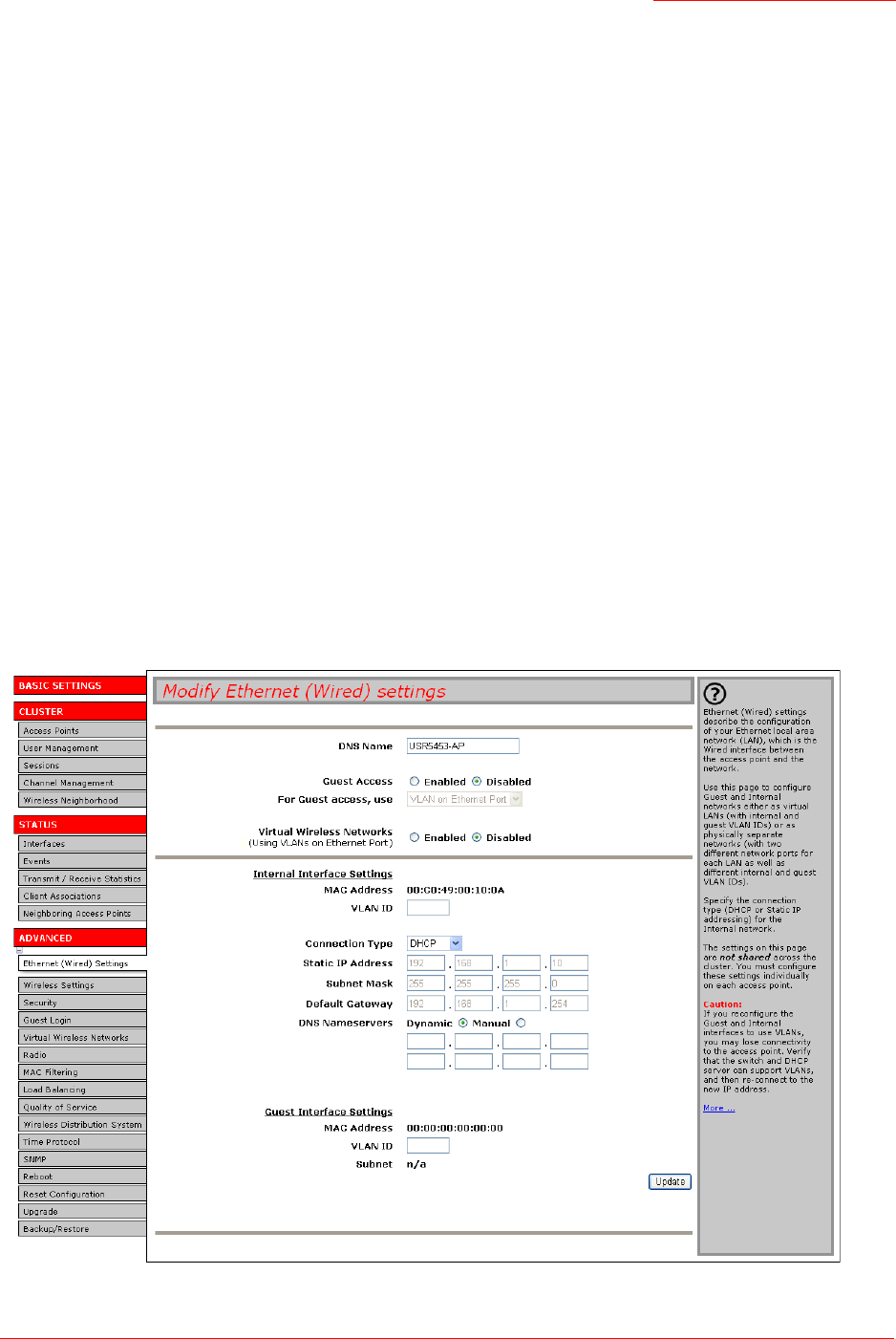
Professional Access Point
Administrator Guide
Ethernet (Wired) Settings - 80
•Navigating to Ethernet (Wired) Settings
•Setting the DNS Name
•Managing Guest Access
•Configuring an Internal LAN and a Guest Network
•Enabling and Disabling Guest Access
•Specifying a Virtual Guest Network
•Enabling and Disabling Virtual Wireless Networks on the Access Point
•Configuring Internal Interface Ethernet Settings
•Configuring Guest Interface Ethernet (Wired) Settings
•Updating Settings
Navigating to Ethernet (Wired) Settings
To set the wired address for an access point, click the Advanced menu’s Ethernet (Wired) Settings tab, and
update the fields as described below.

Professional Access Point
Administrator Guide
Ethernet (Wired) Settings - 81
Setting the DNS Name
Managing Guest Access
You can provide controlled guest access over an isolated network and a secure internal LAN on the same
Professional Access Point.
Configuring an Internal LAN and a Guest Network
A Local Area Network (LAN) is a communications network covering a limited area, for example, one floor
of a building. A LAN connects multiple computers and other network devices like storage and printers.
Ethernet is the most common technology for implementing a LAN. Wi-Fi (IEEE) is another very popular
LAN technology.
The Professional Access Point allows you to configure two different LANs on the same access point: one
for a secure internal LAN and another for a public guest network with no security and little or no access to
internal resources. To configure these networks, you need to provide both wireless and Ethernet (wired)
settings.
Information on how to configure the Ethernet (wired) settings is provided in the sections below.
(For information on how to configure the wireless settings, see “Wireless Settings” on page 87. For an
overview of how to set up the Guest interface, see “Guest Login” on page 111.)
Enabling and Disabling Guest Access
The Professional Access Point ships with the Guest Access feature disabled by default. If you want to
Field Description
DNS Name Enter the DNS name for the access point in the text box.
This is the host name. It may be provided by your ISP or network administrator,
or you can provide your own.
The rules for system names are:
• This name can be up to 20 characters long.
• Only letters, numbers, and dashes are allowed.
• The name must start with a letter and end with either a letter or a number.

Professional Access Point
Administrator Guide
Ethernet (Wired) Settings - 82
provide guest access on your access point, enable Guest Access on the Ethernet (Wired) Settings tab.
Specifying a Virtual Guest Network
If you enable Guest Access, you must represent both an Internal and a Guest Network on this access point
virtually, by connecting the LAN port on the access point to a tagged port on a VLAN-capable switch and
then defining two different virtual LANs on the Ethernet (Wired) Settings page. (For more information, see
“Guest Login” on page 111.)
Choose virtually separate internal and guest LANs as described below.
Enabling and Disabling Virtual Wireless Networks on the Access Point
If you want to configure the Internal network as a VLAN (whether or not you have a Guest network
configured), you can enable Virtual Wireless Networks on the access point.
You must enable this feature if you want to configure additional virtual networks on VLANs on the
Advanced menu’s Virtual Wireless Networks page as described in “Virtual Wireless Networks” on
Field Description
Guest Access By default, the Professional Access Point ships with Guest Access disabled.
• To enable Guest Access, click Enabled.
• To disable Guest Access, click Disabled.
Field Description
Guest Access •Select Enabled to enable Guest Access. (If you choose this option, you must
select VLANs on the next setting For Guest access, use, and then provide
details on VLAN or wired setting for the Guest Network on the rest of the
page.)
•Select Disabled to disable Guest Access
For Guest access, use Specify a virtually separate guest network on this access point:
• Choose VLAN on Ethernet Port. This will enable the VLAN settings where you
must provide a VLAN ID. See also “Configuring Guest Interface Ethernet
(Wired) Settings” on page 85.
Caution: If you reconfigure the Guest and Internal interfaces to use VLANs,
you may lose connectivity to the access point. First, be sure to verify that the
switch and DHCP server you are using can support VLANs per the IEEE
802.1Q standard. After configuring the VLAN on the Advanced menu’s
Ethernet (Wired) Settings page, physically reconnect the Ethernet cable on the
switch to the tagged packet (VLAN) port. Then, reconnect via the Web User
Interface to the new IP address. (If necessary, check with the infrastructure
support administrator regarding the VLAN and DHCP configurations.)

Professional Access Point
Administrator Guide
Ethernet (Wired) Settings - 83
page 115.
Configuring Internal Interface Ethernet Settings
To configure Ethernet (Wired) settings for the Internal LAN, fill in the fields as described below.
Field Description
Virtual Wireless Networks
(Using VLANs on Ethernet Port)
•Select Enabled to enable VLANs for the Internal network and for
additional networks. If you choose this option, you can run the Internal
network on a VLAN whether or not you have Guest Access configured
and you can set up additional networks on VLANs using the Advanced
menu’s Virtual Wireless Networks page as described in “Virtual Wireless
Networks” on page 115.
•Select Disabled to disable the VLAN for the Internal network, and for any
additional virtual networks on this access point.
Field Description
MAC Address Shows the MAC address for the Internal network interface for the LAN port on this
access point. This is a read-only field.
VLAN ID If you choose to configure Internal and Guest networks by VLANs, this field is ena-
bled.
Provide a number between 1 and 4094 for the Internal VLAN.
This will cause the access point to send DHCP requests with the VLAN tag. The
switch and the DHCP server must support VLAN IEEE 802.1Q frames. The access
point must be able to reach the DHCP server.

Professional Access Point
Administrator Guide
Ethernet (Wired) Settings - 84
Connection Type You can select DHCP or Static IP.
The Dynamic Host Configuration Protocol (DHCP) is a protocol that specifies how a
centralized server can provide network configuration information to devices on the
network. A DHCP server offers a lease to the client. The information supplied
includes the IP addresses and netmask plus the address of its DNS servers and
gateway.
Static IP indicates that all network settings are provided manually. You must provide
the IP address for the Professional Access Point, its subnet mask, the IP address of
the default gateway, and the IP address of at least one DNS name server.
If you select DHCP, the Professional Access Point will acquire its IP Address, subnet
mask, and DNS and gateway information from the DHCP Servers.
If you select Static IP, fill in the Static IP Address, Subnet Mask, and Default Gateway
fields.
Caution: If you do not have a DHCP server on the Internal network and do not plan
to use one, the first thing you must do after bringing up the access point is change
the connection type from DHCP to static IP. When you change the connection type
to static IP, you can either assign a new Static IP Address to the access point or
continue using the default address. USRobotics recommends assigning a new
address so that if later you bring up another Professional Access Point on the same
network, the IP addresses for the two APs will be unique.
If you need to recover the default static IP address, you can do so by resetting the
access point to the factory defaults as described in “Reset Configuration” on
page 159.
Static IP Address Enter the static IP address in the text boxes.
This field is enabled only if you selected Static IP as the connection type.
Subnet Mask Enter the Subnet Mask in the text boxes. You must obtain this information from your
ISP or network administrator.
This field is enabled only if you selected Static IP as the connection type.
Default Gateway Enter the Default Gateway in the text boxes.
This field is enabled only if you selected Static IP as the connection type.
DNS Nameservers The Domain Name Service (DNS) is a system that resolves the descriptive name
(domainname) of a network resource (for example,
www.usr.com
) to its numeric
IP address (for example,
66.93.138.219
). A DNS server is called a Nameserver.
There are usually two Nameservers; a Primary Nameserver and a Secondary
Nameserver.
You can choose Dynamic or Manual mode.
• If you choose Manual, assign static IP addresses for the DNS servers manually.
• If you choose Dynamic, the IP addresses for the DNS servers will be assigned
automatically via DHCP. This option is only available if you specified DHCP for the
Connection Type.
Field Description

Professional Access Point
Administrator Guide
Ethernet (Wired) Settings - 85
Configuring Guest Interface Ethernet (Wired) Settings
To configure Ethernet (Wired) Settings for the Guest interface, fill in the fields as described below.
Updating Settings
To apply your changes, click Update.
Field Description
MAC Address Shows the MAC address for the Guest interface for the LAN port on this access
point. This is a read-only field.
VLAN ID If you choose to configure Internal and Guest networks by VLANs, this field will be
enabled.
Provide a number between 1 and 4094 for the Guest VLAN. Be sure to assign a dif-
ferent VLAN ID than the one used for the Internal network.
Subnet Shows the subnetwork address for the Guest interface. For example, 192.168.1.0.

Professional Access Point
Administrator Guide
Ethernet (Wired) Settings - 86

Professional Access Point
Administrator Guide
Wireless Settings - 87
Wireless Settings
Wireless settings describe aspects of the local area network (LAN) related specifically to the radio device
in the access point (802.11 Mode and Channel) and to the network interface to the access point (MAC
address for access point and wireless network name, also known as SSID).
The following sections describe how to configure the wireless address and related settings on the
Professional Access Point:
•Navigating to Wireless Settings
•Configuring 802.11d Regulatory Domain Support
•Configuring the Radio Interface
•Configuring Internal LAN Wireless Settings
•Configuring Guest Network Wireless Settings
•Updating Settings
Navigating to Wireless Settings
To set the wireless address for an access point, click the Advanced menu’s Wireless Settings tab, and
update the fields as described below.
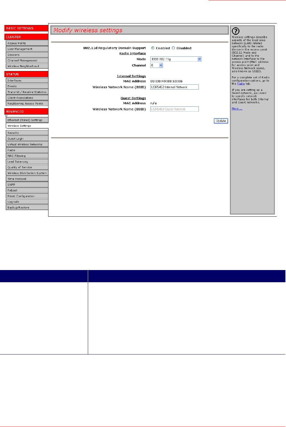
Professional Access Point
Administrator Guide
Wireless Settings - 88
Configuring 802.11d Regulatory Domain Support
You can enable or disable IEEE 802.11d Regulatory Domain Support to broadcast the access point
country code information as described below.
Field Description
802.11d Regulatory Domain Support Enabling support for IEEE 802.11d on the access point causes the access
point to broadcast which country it is operating in as a part of its beacons:
• To enable 802.11d regulatory domain support click Enabled.
• To disable 802.11d regulatory domain support click Disabled.
Note: IEEE 802.11d defines standard rules for the operation of IEEE 802.11
wireless LANs in any country without reconfiguration. IEEE 802.11d allows
client devices to operate in any country without reconfiguration.

Professional Access Point
Administrator Guide
Wireless Settings - 89
Configuring the Radio Interface
The radio interface allows you to set the radio Channel and 802.11 mode as described below.
Configuring Internal LAN Wireless Settings
The Internal Settings describe the MAC Address and Network Name (also known as the SSID) for the
internal Wireless LAN (WLAN) as described below.
Field Description
Mode The Mode defines the Physical Layer (PHY) standard being used by the radio.
Select one of these modes:
• IEEE 802.11b
• IEEE 802.11g
Channel Select the Channel. The range of channels is 1 through 11.
The Channel defines the portion of the radio spectrum the radio uses for trans-
mitting and receiving. Each mode offers a number of channels, depending on
how the spectrum is licensed by national and transnational authorities such as
the Federal Communications Commission (FCC) or the International Telecom-
munication Union (ITU-R).
The default is Auto, which picks the least busy channel at startup time.
Field Description
MAC Address Shows the MAC address for the Internal interface for this access point. This is
a read-only field that you cannot change.
Although this access point is physically a single device, it can be represented
on the network as two or more nodes each with a unique MAC Address. This is
accomplished by using multiple Basic Service Set Identifiers (BSSIDs) for a
single access point.
The MAC address shown for the Internal access point is the BSSID for the
Internal interface.
Wireless Network Name (SSID) Enter the SSID for the internal WLAN.
The Service Set Identifier (SSID) is an alphanumeric string of up to 32 charac-
ters that uniquely identifies a wireless local area network. It is also referred to
as the Network Name. There are no restrictions on the characters that may be
used in an SSID.

Professional Access Point
Administrator Guide
Wireless Settings - 90
Configuring Guest Network Wireless Settings
The Guest Settings describe the MAC Address (read-only) and wireless network name (SSID) for the Guest
Network as described below. Configuring an access point with two different network names (SSIDs) allows
you to implement the Guest interface feature on the Professional Access Point. For more information, see
“Guest Login” on page 111.
Updating Settings
To apply your changes, click Update.
Field Description
MAC Address Shows the MAC address for the Guest interface for this access point. This is a
read-only field.
Although this access is point is physically a single device, it can be represented
on the network as two or more nodes each with a unique MAC Address. This is
accomplished by using multiple Basic Service Set Identifiers (BSSID) for a sin-
gle access point.
The MAC address shown for the Guest access point is the BSSID for the
Guest interface.
Wireless Network Name (SSID) Enter the SSID for the guest network.
The Service Set Identifier (SSID) is an alphanumeric string of up to 32 charac-
ters that uniquely identifies a wireless local area network. It is also referred to
as the Network Name. There are no restrictions on the characters that may be
used in an SSID.
For the guest network, provide an SSID that is different from the internal SSID
and easily identifiable as the guest network.

Professional Access Point
Administrator Guide
Security - 91
Security
The following sections describe how to configure security settings on the Professional Access Point:
•Understanding Security Issues on Wireless Networks
•How Do I Know Which Security Mode to Use?
•Comparison of Security Modes for Key Management, Authentication and Encryption Algorithms
•Does Prohibiting the Broadcast of SSID Enhance Security?
•How Does Station Isolation Protect the Network?
•Navigating to Security Settings
•Configuring Security Settings
•Broadcast SSID, Station Isolation, and Security Mode
•None
•Static WEP
•IEEE 802.1x
•WPA/WPA2 Personal (PSK)
•WPA/WPA2 Enterprise (RADIUS)
•Updating Settings
Understanding Security Issues on Wireless Networks
Wireless mediums are inherently less secure than wired mediums. For example, an Ethernet NIC trans-
mits its packets over a physical medium such as coaxial cable or twisted pair. A wireless NIC broadcasts
radio signals over the air allowing a wireless LAN to be easily tapped without physical access or sophisti-
cated equipment. A hacker equipped with a laptop, a wireless NIC, and a bit of knowledge can easily
attempt to compromise your wireless network. By using a sophisticated antenna on the client, a hacker
may even be able to connect to the network from many miles away.
The Professional Access Point provides a number of authentication and encryption schemes to ensure
that your wireless infrastructure is accessed only by the intended users. The details of each security mode
are described in the sections below.
How Do I Know Which Security Mode to Use?
In general, USRobotics recommends that on your Internal network you use the most robust security mode
that is feasible in your environment. When configuring security on the access point, you first must choose
the security mode. Then, in some modes you must choose an authentication algorithm and whether to
allow clients not using the specified security mode to associate.

Professional Access Point
Administrator Guide
Security - 92
Wi-Fi Protected Access (WPA) with Remote Authentication Dial-In User Service (RADIUS) using the
CCMP (AES) encryption algorithm provides the best data protection available and is clearly the best
choice if all client devices are equipped with WPA supplicants. However, backward compatibility or
interoperability issues with clients or even with other access points may require that you configure WPA
with RADIUS with a different encryption algorithm or choose one of the other security modes.
However, security may not be as much of a priority on some types of networks. If you are simply providing
internet and printer access, as on a guest network, None may be the appropriate choice. To prevent clients
from accidentally discovering and connecting to your network, you can disable the broadcast SSID so that
your network name is not advertised. If the network is sufficiently isolated from access to sensitive
information, this may offer enough protection in some situations. This level of protection is the only one
offered for guest networks, and also may be the right convenience trade-off for other situations in which
the priority is making it as easy as possible for clients to connect. (See “Does Prohibiting the Broadcast of
SSID Enhance Security?” on page 96.)
Following is a brief discussion of the factors that make one mode more secure than another, a description
of each mode offered, and when to use each mode.
Comparison of Security Modes for Key Management, Authentication and Encryption
Algorithms
The major factors that determine the effectiveness of a security protocol are:
• How the protocol manages keys
• Presence or absence of integrated user authentication in the protocol
• Encryption algorithm or formula the protocol uses to encode and decode the data
Following is a list of the security modes available on the Professional Access Point along with a description
of the key management, authentication, and encryption algorithms used in each mode. Each discussion
includes suggestions as to when one mode might be more appropriate than another.
•When to Use No Security
•When to Use Static WEP
•When to Use IEEE 802.1x
•When to Use WPA/WPA2 Personal (PSK)
•When to Use WPA/WPA2 Enterprise (RADIUS)
When to Use No Security
None is a security mode option. In this mode, the data is not encrypted. Instead, the data is sent as plain
text across the network. No key management, data encryption, or user authentication is used.
RECOMMENDATIONS
None is not recommended for regular use on the Internal network because it is not secure.
You must run the Guest network with no security. The Guest network is, by definition, an insecure LAN

Professional Access Point
Administrator Guide
Security - 93
always virtually separated from any sensitive information on the Internal LAN.
Therefore, use None on the Guest network, and on the Internal network for initial setup, testing, or problem
solving only.
SEE ALSO
For information on how to configure this mode, see “None” on page 98 under “Configuring Security
Settings”.
When to Use Static WEP
Static Wired Equivalent Privacy (WEP) is a data encryption protocol for 802.11 wireless networks. All
wireless stations and access points on the network are configured with a static 64-bit (40-bit secret key +
24-bit initialization vector (IV)) or 128-bit (104-bit secret key + 24-bit IV) Shared Key for data encryption.
RECOMMENDATIONS
Static WEP was designed to provide security equivalent of sending unencrypted data through an Ethernet
connection, however it has major flaws and it does not provide even this intended level of security.
Therefore, Static WEP is not recommended as a secure mode. The only time to use Static WEP is when
interoperability issues make it the only option available to you and you are not concerned with the potential
of exposing the data on your network.
SEE ALSO
For information on how to configure Static WEP security mode, see “Static WEP” on page 99 under
“Configuring Security Settings”.
When to Use IEEE 802.1x
IEEE 802.1x is the standard for passing the Extensible Authentication Protocol (EAP) over an 802.11
wireless network using a protocol called EAP Encapsulation Over LANs (EAPOL). This is a newer, more
secure standard than Static WEP.
Key Management Encryption Algorithm User Authentication
Static WEP uses a fixed key that is
provided by the administrator. WEP
keys are indexed in different slots
(up to four on the Professional
Access Point).
The client devices must have the
same key indexed in the same slot
to access data on the access point.
An RC4 stream cipher is used to
encrypt the frame body and cyclic
redundancy checking (CRC) of each
802.11 frame.
If you set the Authentication Algorithm
to Shared Key, this protocol provides
a rudimentary form of user authenti-
cation.
However, if the Authentication Algo-
rithm is set to Open System, no
authentication is performed.
If the algorithm is set to Both, only
WEP clients are authenticated.

Professional Access Point
Administrator Guide
Security - 94
RECOMMENDATIONS
IEEE 802.1x mode is a better choice than Static WEP because keys are dynamically generated and
changed periodically. However, the encryption algorithm used is the same as that of Static WEP and is
therefore not as reliable as the more advanced encryption methods such as TKIP and CCMP (AES) used
in Wi-Fi Protected Access (WPA) or WPA2.
Additionally, compatibility issues may be cumbersome because of the variety of authentication methods
supported and the lack of a standard implementation method.
Therefore, IEEE 802.1x mode is not as secure a solution as Wi-Fi Protected Access (WPA) or WPA2.
SEE ALSO
For information on how to configure IEEE 802.1x security mode, see “IEEE 802.1x” on page 104 under
“Configuring Security Settings”.
When to Use WPA/WPA2 Personal (PSK)
Wi-Fi Protected Access 2 (WPA2) Personal Pre-Shared Key (PSK) is an implementation of the Wi-Fi
Alliance IEEE 802.11i standard, which includes Advanced Encryption Algorithm (AES), Counter mode/
CBC-MAC Protocol (CCMP), and Temporal Key Integrity Protocol (TKIP) mechanisms. This mode offers
the same encryption algorithms as WPA 2 with RADIUS but without the ability to integrate a RADIUS
server for user authentication.
This security mode is backward compatible for wireless clients that support only the original WPA.
Key Management Encryption Algorithm User Authentication
IEEE 802.1x provides dynamically-
generated keys that are periodically
refreshed.
There are different Unicast keys for
each station.
An RC4 stream cipher is used to
encrypt the frame body and cyclic
redundancy checking (CRC) of each
802.11 frame.
IEEE 802.1x mode supports a vari-
ety of authentication methods, like
certificates, Kerberos, and public
key authentication with a RADIUS
server.
You have a choice of using the Pro-
fessional Access Point embedded
RADIUS server or an external
RADIUS server. The embedded
RADIUS server supports Protected
EAP (PEAP) and MSCHAP V2.
Key Management Encryption Algorithms User Authentication
WPA/WPA2 Personal (PSK) pro-
vides dynamically-generated keys
that are periodically refreshed.
There are different Unicast keys for
each station.
•Temporal Key Integrity Protocol
(TKIP)
•Counter mode/CBC-MAC Proto-
col (CCMP) Advanced Encryption
Standard (AES)
The use of a Pre-Shared (PSK) key
provides user authentication similar
to that of shared keys in WEP.

Professional Access Point
Administrator Guide
Security - 95
RECOMMENDATIONS
WPA/WPA2 Personal (PSK) is not recommended for use with the Professional Access Point when WPA/
WPA2 Enterprise (RADIUS) is an option.
USRobotics recommends that you use WPA/WPA2 Enterprise (RADIUS) mode instead, unless you have
interoperability issues that prevent you from using this mode.
For example, some devices on your network may not support WPA or WPA2 with EAP talking to a
RADIUS server. Embedded printer servers or other small client devices with very limited space for
implementation may not support RADIUS. For such cases, USRobotics recommends that you use WPA/
WPA2 Personal (PSK).
SEE ALSO
For information on how to configure this security mode, see “WPA/WPA2 Personal (PSK)” on page 105.
When to Use WPA/WPA2 Enterprise (RADIUS)
Wi-Fi Protected Access 2 (WPA2) with Remote Authentication Dial-In User Service (RADIUS) is an
implementation of the Wi-Fi Alliance IEEE 802.11i standard, which includes Advanced Encryption
Standard (AES), Counter mode/CBC-MAC Protocol (CCMP), and Temporal Key Integrity Protocol (TKIP)
mechanisms. This mode requires the use of a RADIUS server to authenticate users. WPA/WPA2
Enterprise (RADIUS) provides the best security available for wireless networks.
This security mode also provides backward compatibility for wireless clients that support only the original
WPA.
RECOMMENDATIONS
WPA/WPA2 Enterprise (RADIUS) mode is the recommended mode. The CCMP (AES) and TKIP
encryption algorithms used with WPA modes are far superior to the RC4 algorithm used for Static WEP or
IEEE 802.1x modes. Therefore, CCMP (AES) or TKIP should be used whenever possible. All WPA modes
allow you to use these encryption schemes, so WPA security modes are recommended above the others
when using WPA is an option.
Additionally, this mode incorporates a RADIUS server for user authentication, which gives it an edge over
WPA/WPA2 Personal (PSK) mode.
Use the following guidelines for choosing options within the WPA/WPA2 Enterprise (RADIUS) mode
security mode:
Key Management Encryption Algorithms User Authentication
WPA/WPA2 Enterprise (RADIUS)
mode provides dynamically-gener-
ated keys that are periodically
refreshed.
There are different Unicast keys for
each station.
•Temporal Key Integrity Protocol
(TKIP)
•Counter mode/CBC-MAC Proto-
col (CCMP) Advanced Encryption
Standard (AES)
Remote Authentication Dial-In User
Service (RADIUS)
You have a choice of using the Pro-
fessional Access Point embedded
RADIUS server or an external
RADIUS server. The embedded
RADIUS server supports Protected
EAP (PEAP) and MSCHAP V2.

Professional Access Point
Administrator Guide
Security - 96
1. The best security you can have to-date on a wireless network is WPA/WPA2 Enterprise (RADIUS)
mode using CCMP (AES) encryption algorithm. AES is a symmetric 128-bit block data encryption
technique that works on multiple layers of the network. It is the most effective encryption system
currently available for wireless networks. If all clients or other APs on the network are WPA/CCMP
compatible, use this encryption algorithm. If all clients are WPA2 compatible, choose to support only
WPA2 clients.
2. The second best choice is WPA/WPA2 Enterprise (RADIUS) with the encryption algorithm set to Both
(that is, both TKIP and CCMP). This lets WPA clients without CCMP associate, uses TKIP for encrypt-
ing Multicast and Broadcast frames, and allows clients to select whether to use CCMP or TKIP for Uni-
cast (access-point-to-single-station) frames. This WPA configuration allows more interoperability, at
the expense of some security. Clients that support CCMP can use it for their Unicast frames. If you
encounter access-point-to-station interoperability problems with the Both encryption algorithm setting,
then you will need to select TKIP instead.
3. The third best choice is WPA/WPA2 Enterprise (RADIUS) with the encryption algorithm set to TKIP.
Some clients have interoperability issues with CCMP and TKIP enabled at same time. If you encounter
this problem, then choose TKIP as the encryption algorithm. This is the standard WPA mode, and
most interoperable mode with client wireless software security features. TKIP is the only encryption
algorithm that is being tested in Wi-Fi WPA certification.
SEE ALSO
For information on how to configure this security mode, see “WPA/WPA2 Enterprise (RADIUS)” on
page 107 under “Configuring Security Settings”.
Does Prohibiting the Broadcast of SSID Enhance Security?
You can prohibit the broadcast of the AP’s SSID to discourage stations from automatically discovering
your access point. When the access point’s SSID broadcast is prohibited, the network name is not
displayed in the List of Available Networks on a client device. Instead, the client must have the exact network
name configured in the supplicant before the client will be able to connect.
Prohibiting the SSID broadcast is sufficient to prevent clients from accidentally connecting to your network,
but it will not prevent even the simplest of attempts by a hacker to connect or to monitor insecure traffic.
This offers a minimum level of protection on an otherwise exposed network (such as a guest network)
where the priority is making it easy for clients to get a connection and where no sensitive information is
available.
(See also “Guest Network” on page 98.)
How Does Station Isolation Protect the Network?
When Station Isolation is enabled, the access point blocks communication between wireless clients. The
access point allows data traffic between its wireless clients and wired devices on the network, but not
among wireless clients.
The traffic blocking extends to wireless clients connected to the network via WDS links; these clients
cannot communicate with each other when Station Isolation is on. See “Wireless Distribution System” on
page 143 for more information about WDS.
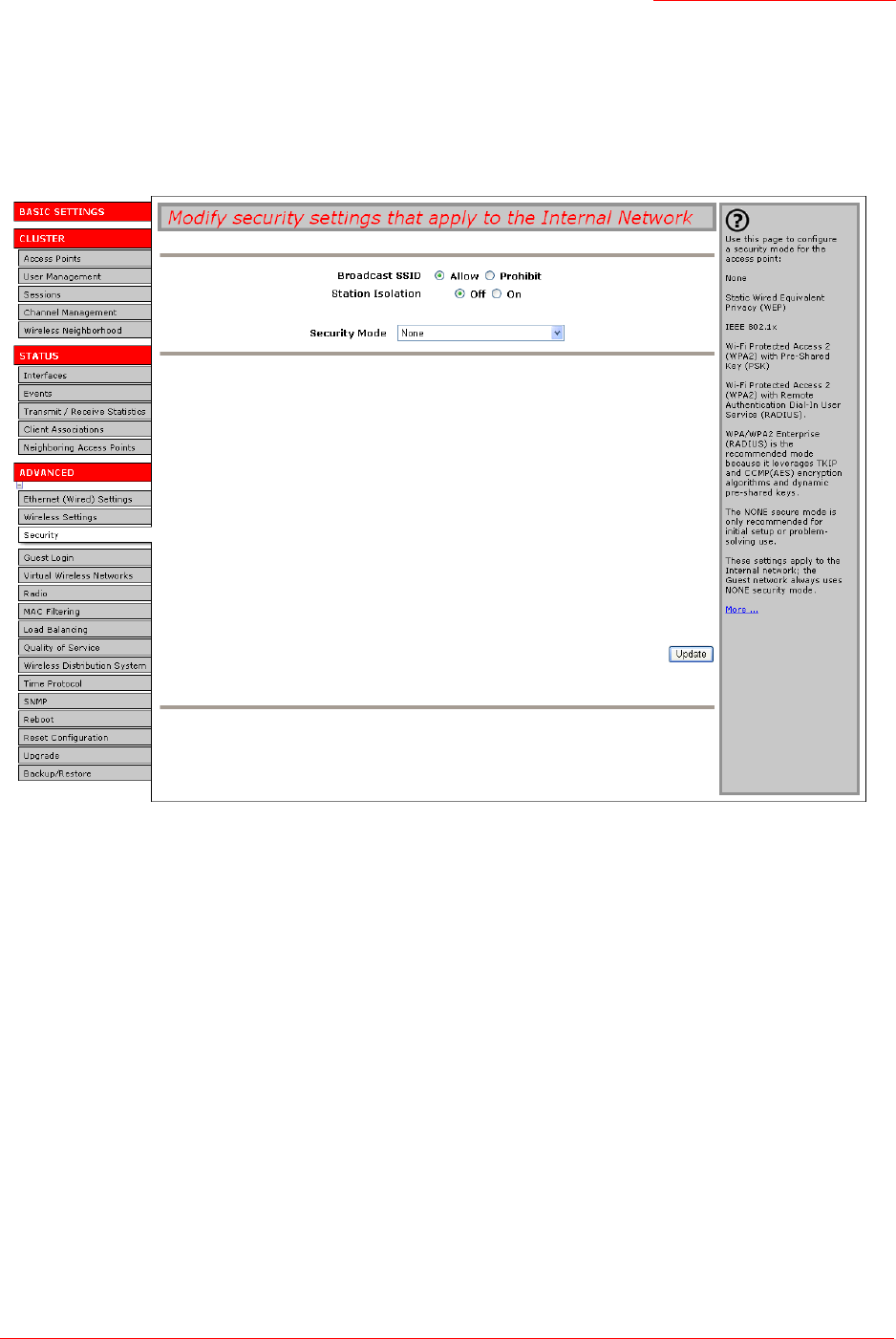
Professional Access Point
Administrator Guide
Security - 97
Navigating to Security Settings
To set the security mode, click the Advanced menu’s Security tab, and update the fields as described
below.
Configuring Security Settings
The following configuration information explains how to configure security modes on the access point.
Keep in mind that each wireless client that wants to exchange data with the access point must be
configured with the same security mode and encryption key settings consistent with access point security.
Broadcast SSID, Station Isolation, and Security Mode
To configure security on the access point, select a security mode and fill in the related fields as described
in the following table. You can also allow or prohibit the Broadcast SSID and enable or disable Station
Notes
Security modes other than None apply only to configuration of the Internal network. On the Guest net-
work, you can use only None. (For more information about guest networks, see “Guest Login” on
page 111.)

Professional Access Point
Administrator Guide
Security - 98
Isolation as extra precautions as mentioned below.
None
None means that any data transferred to and from the Professional Access Point is not encrypted.
There are no further options for this mode.Running without security can be useful during initial network
configuration or for problem solving, but it is not recommended for regular use on the Internal network
because it is not secure.
Guest Network
None is the only mode in which you can run the Guest network, which is by definition an easily accessible,
Field Description
Broadcast SSID Select the Broadcast SSID setting by clicking Allow or Prohibit.
By default, the access point broadcasts the Service Set Identifier (SSID) in its
beacon frames.
You can prohibit this broadcast to discourage stations from automatically dis-
covering your access point. When the access point’s broadcast SSID is sup-
pressed, the network name will not be displayed in the List of Available Networks
on a client device. Instead, the client must have the exact network name con-
figured in the supplicant before the client will be able to connect.
Station Isolation Select Off to disable station isolation or On to enable it.
• When station isolation is Off, wireless clients can communicate with one
another normally by sending traffic through the access point.
• When station isolation is On, the access point blocks communication
between wireless clients. The access point allows data traffic between its
wireless clients and wired devices on the network, but not among wireless
clients. The traffic blocking extends to wireless clients connected to the
network via WDS links; these clients cannot communicate with each other
when station isolation is on. See “Wireless Distribution System” on page 143
for more information about WDS.
Security Mode Select the Security Mode. Select one of the following:
• None
• Static WEP
• IEEE 802.1x
• WPA/WPA2 Personal (PSK)
• WPA/WPA2 Enterprise (RADIUS)
For a Guest network, only the None setting can be used. (For more information,
see “Guest Login” on page 111.)
Security modes other than None apply only to configuration of the Internal net-
work.
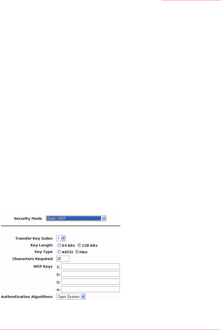
Professional Access Point
Administrator Guide
Security - 99
insecure LAN always virtually separated from any sensitive information on the Internal LAN. For example,
the guest network might simply provide internet and printer access for day visitors.
The absence of security on the Guest network is designed to make it as easy as possible for guests to get
a connection without having to program any security settings in their clients.
For a minimum level of protection on a guest network, you can choose to prohibit the broadcast of the
SSID, discouraging client devices from automatically discovering your access point. (See also “Does
Prohibiting the Broadcast of SSID Enhance Security?” on page 96).
For more about the Guest network, see “Guest Login” on page 111.
Static WEP
Wired Equivalent Privacy (WEP) is a data encryption protocol for 802.11 wireless networks. All wireless
stations and access points on the network are configured with a static 64-bit (40-bit secret key + 24-bit ini-
tialization vector (IV)) or 128-bit (104-bit secret key + 24-bit IV) Shared Key for data encryption.
You cannot mix 64-bit and 128-bit WEP keys between the access point and its clients.
Static WEP is not the most secure mode available, but it offers more protection than None as it does pre-
vent an outsider from easily sniffing out unencrypted wireless traffic. (For more secure modes, see the sec-
tions on “IEEE 802.1x” on page 104, “WPA/WPA2 Enterprise (RADIUS)” on page 107, or “WPA/WPA2
Personal (PSK)” on page 105.)
WEP encrypts data moving across the wireless network based on a static key. (The encryption algorithm is
a stream cipher called RC4.)
The access point uses a key to transmit data to the clients. Each client must use that same key to decrypt
data it receives from the access point.
Clients can use different keys to transmit data to the access point. (Or they can all use the same key, but
this is less secure because it means one station can decrypt the data being sent by another.)
If you selected Static WEP as the security mode, provide the following on the access point settings:

Professional Access Point
Administrator Guide
Security - 100
.
Field Description
Transfer Key Index Select a key index. Key indexes 1 through 4 are available. The default is 1.
The transfer key index indicates which WEP key the access point will use to encrypt
the data it transmits.
Key Length Specify one of the following lengths for the key:
•64 bits
•128 bits
Key Type Select one of the following key types:
•ASCII
•Hex
Characters Required Indicates the number of characters required in the WEP key.
The number is updated automatically based on how you set Key Length and Key
Type.
WEP Keys You can specify up to four WEP keys. In each text box, enter a string of characters
for one key.
If you selected ASCII, enter any combination of integers and letters
0-9
,
a-z
, and
A-Z
.
If you selected HEX, enter hexadecimal digits (any combination of
0-9
and
a-f
or
A-F
).
Use the same number of characters for each key as specified in the Characters
Required field. These are the RC4 WEP keys shared with the stations using the
access point.
Each client must be configured to use one of these same WEP keys in the same
slot as specified here on the access point. (See “Rules to Remember for Static
WEP” on page 101.)

Professional Access Point
Administrator Guide
Security - 101
Rules to Remember for Static WEP
• All clients must have the Wireless LAN (WLAN) security set to WEP, and all clients must have one of
the WEP keys specified on the access point in order to decode access-point-to-station data transmis-
sions.
• The access point must have all keys used by clients for station-to-access-point transmit so that it can
decode the station transmissions.
• The same key must occupy the same slot on all nodes (access point and clients). For example, if the
access point defines
abc123
key as WEP key 3, then the clients must define that same string as WEP
key 3.
• On some wireless client software (like Funk Odyssey), you can configure multiple WEP keys and
define a client transfer key index, then set the stations to encrypt the data they transmit using different
keys. This ensures that neighbouring APs cannot decode each other’s transmissions.
Authentication Algorithm The authentication algorithm defines the method used to determine whether a client
is allowed to associate with an access point when static WEP is the security mode.
Specify the authentication algorithm you want to use by choosing one of the follow-
ing:
• Open System
•Shared Key
•Both
Open System authentication allows any client to associate with the access point
whether that client has the correct WEP key or not. This algorithm is also used in
None, IEEE 802.1x, and WPA modes. When the authentication algorithm is set to
Open System, any client can associate with the access point.
That a client is allowed to associate does not ensure that the client can exchange
traffic with an access point. A client must have the correct WEP key to be able to
successfully access and decrypt data from an access point, and to transmit reada-
ble data to the access point.
Shared Key authentication requires the client to have the correct WEP key in order to
associate with the access point. When the authentication algorithm is set to Shared
Key, a station with an incorrect WEP key will not be able to associate with the
access point.
Both is the default. When the authentication algorithm is set to Both:
• Clients configured to use WEP in shared key mode must have a valid WEP key
in order to associate with the access point.
• Clients configured to use WEP in an open system mode (shared key mode not
enabled) will be able to associate with the access point even if they do not have
the correct WEP key.
Field Description
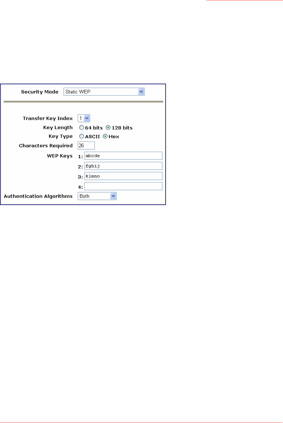
Professional Access Point
Administrator Guide
Security - 102
Example of Using Static WEP
For a simple example, suppose that you configure three WEP keys on the access point. In this example,
the Transfer Key Index for the access point is set to 3. This means that the WEP key in slot 3 is the key
that the access point will use to encrypt the data it sends.
Figure 7. Setting the Access Point Transfer Key on the Access Point.
You must then set all clients to use WEP and provide each client with one of the slot and key combinations
you defined on the access point.
The following example will set WEP key 1 on a Windows client.
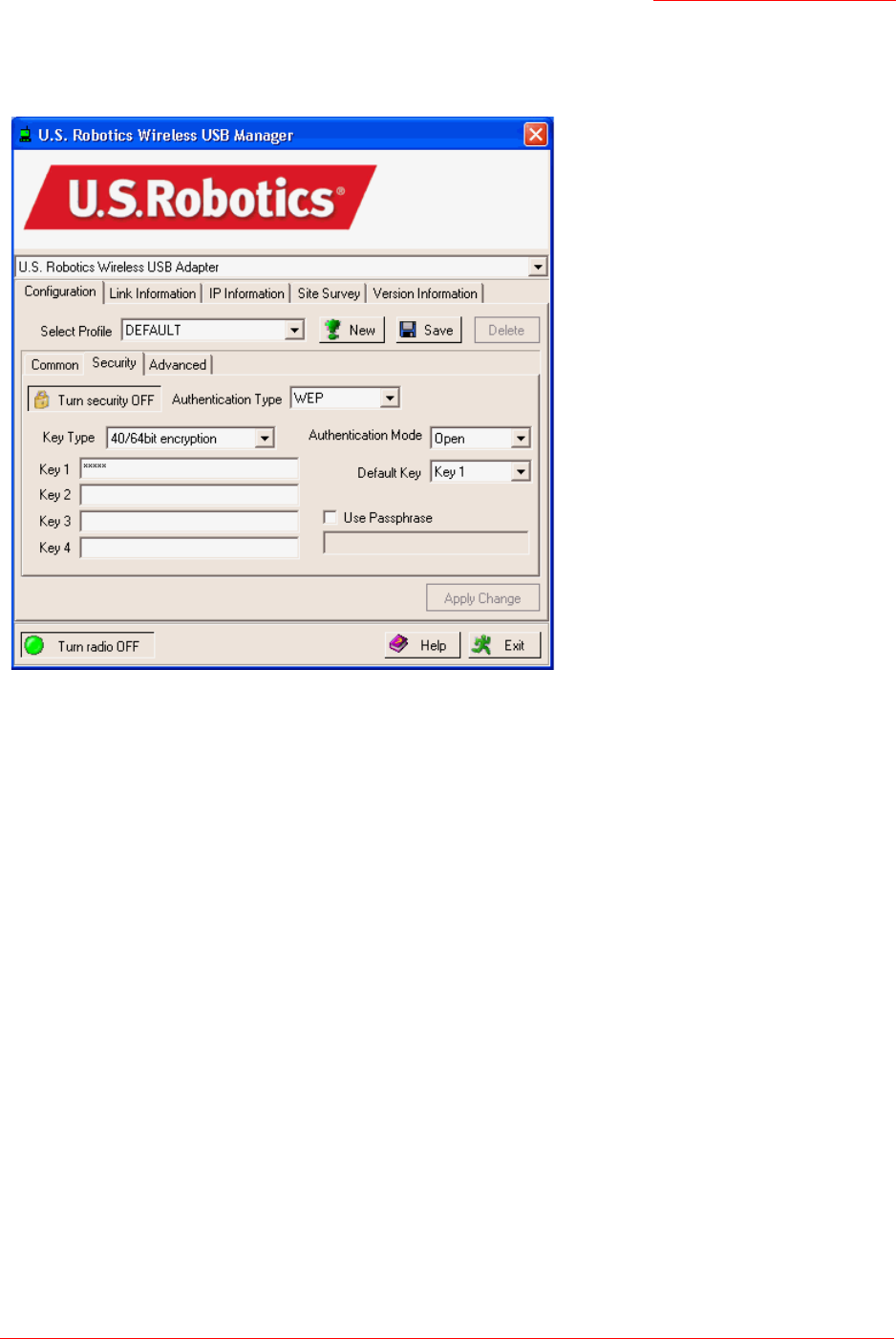
Professional Access Point
Administrator Guide
Security - 103
Figure 8. Providing a Wireless Client with a WEP Key
If you have a second client, that client also needs to have one of the WEP keys defined on the access
point. You could give it the same WEP key that you gave to the first station. Or, for a more secure solution,
you could give the second station a different WEP key (key 2, for example) so that the two stations cannot
decrypt each other’s transmissions.
STATIC WEP WITH TRANSFER KEY INDEXES ON CLIENT DEVICES
Some Wireless client software, such as like Funk Odyssey, lets you configure multiple WEP keys and set a
transfer index on the client; then you can specify different keys to be used for station-to-access-point
transmissions. (The standard Windows wireless client software does not allow you to do this.)
To build on the previous example, using Funk Odyssey client software you could give each of the clients
WEP key 3 so that they can decode the access point transmissions with that key and also give client 1
WEP key 1 and set this as the client 1’s transfer key index. You could then give client 2 WEP key 2 and set
this as client 2’s transfer key index.
Figure 9 illustrates the dynamics of the access point and two clients using multiple WEP keys and a
transfer key index.
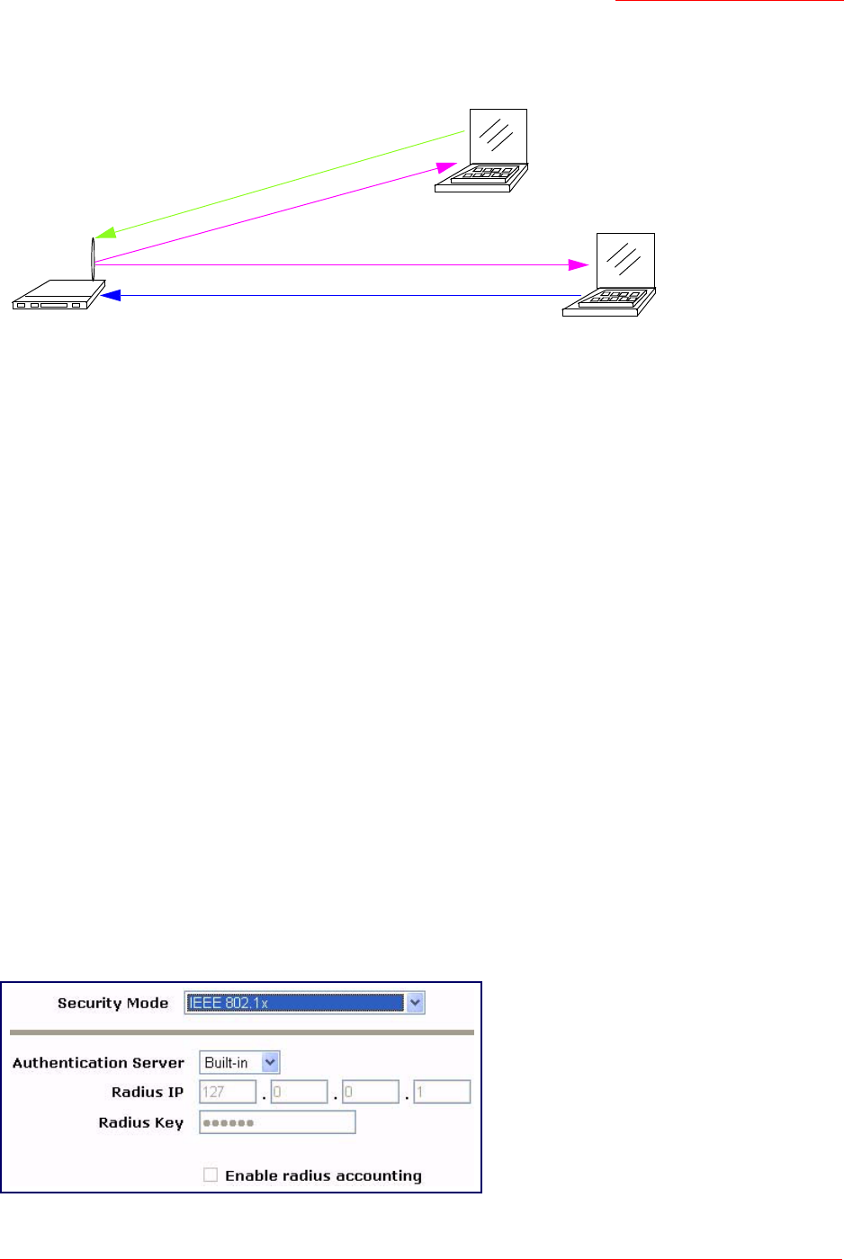
Professional Access Point
Administrator Guide
Security - 104
Figure 9. Example of Using Multiple WEP Keys and Transfer Key Index on Client Devices
IEEE 802.1x
IEEE 802.1x is the standard that defines port-based authentication and provides a framework for
implementing key management. Extensible Authentication Protocol (EAP) packets are sent over an IEEE
802.11 wireless network using a protocol called EAP Encapsulation Over LANs (EAPOL). IEEE 802.1x
provides dynamically-generated keys that are periodically refreshed. An RC4 stream cipher is used to
encrypt the frame body and cyclic redundancy checking (CRC) of each 802.11 frame.
The IEEE 802.1x security mode requires the use of a RADIUS server to authenticate users and requires
configuration of user accounts via the Cluster menu’s User Management page.
The access point requires a RADIUS server capable of EAP, such as the Microsoft Internet Authentication
Server or the Professional Access Point internal authentication server. To work with Windows clients, the
authentication server must support Protected EAP (PEAP) and MSCHAP V2.
When configuring IEEE 802.1x mode, you can use either the embedded RADIUS server or an external
RADIUS server that you provide. The Professional Access Point embedded RADIUS server supports
Protected EAP (PEAP) and MSCHAP V2.
If you use your own RADIUS server, you can use any of a variety of authentication methods that the IEEE
802.1x mode supports, including certificates, Kerberos, and public key authentication. Keep in mind,
however, that the clients must be configured to use the same authentication method being used by the
access point.
If you select IEEE 802.1x Security Mode, you must provide the following:
Access Point transmits to both stations with WEP key 3
Client Station 1
Client Station 2
WEP key 3
WEP key 3
WEP key 2
WEP key 1
can decrypt WEP key 3
transmits in WEP key 1
can decrypt WEP key 3
transmits in WEP key 2

Professional Access Point
Administrator Guide
Security - 105
WPA/WPA2 Personal (PSK)
Wi-Fi Protected Access 2 (WPA2) with Pre-Shared Key (PSK) is a Wi-Fi Alliance IEEE 802.11i standard,
which includes Advanced Encryption Algorithm (AES), Counter mode/CBC-MAC Protocol (CCMP), and
Temporal Key Integrity Protocol (TKIP) mechanisms. The Personal version of WPA2 employs a pre-
shared key (instead of using IEEE 802.1x and EAP as is used in the Enterprise WPA2 security mode). The
PSK is used for an initial check of credentials only.
This security mode is backward-compatible for wireless clients that support the original WPA.
If you select WPA/WPA2 Personal (PSK) Security Mode, you must provide the following:
Field Description
Authentication Server Select one of the following:
•Built-in—To use the authentication server provided with the Professional Access
Point. If you choose this option, you do not have to provide the Radius IP and
Radius Key; they are automatically provided.
•External—To use an external authentication server. If you choose this option you
must supply the Radius IP and Radius Key of the server you want to use.
Note: The RADIUS server is identified by its IP address and UDP port numbers for
the different services it provides.The RADIUS server User Datagram Protocol
(UDP) ports used by the access point are not configurable on the Professional
Access Point. (The access point is hard-coded to use RADIUS server UDP port
1812 for authentication and port 1813 for accounting.)
Radius IP Enter the Radius IP in the text box.
The Radius IP is the IP address of the RADIUS server.
The Professional Access Point internal authentication server is
127.0.0.1
For information on setting up user accounts, see “User Management” on page 43.
Radius Key Enter the Radius Key in the text box.
The Radius Key is the shared secret key for the RADIUS server. The text you enter
will be displayed as "*" characters to prevent others from seeing the RADIUS key
as you type.
(The Professional Access Point internal authentication server key is
secret
.)
This value is never sent over the network.
Enable RADIUS Accounting Click Enable RADIUS Accounting if you want to track and measure the resources that a
particular user has consumed. Resources measured include system time, amount
of data transmitted and received, and so on.

Professional Access Point
Administrator Guide
Security - 106
Field Description
WPA Versions Select the types of clients you want to support:
•WPA—
If all clients on the network support the original
WPA,
but none support the newer
WPA2
, then select
WPA
•WPA2—
If all clients on the network support
WPA2
,
USRobotics
suggests using
WPA2
,
which provides the best security per the
IEEE
802.11i
standard.
•Both—
If you have a mix of clients, some of which support
WPA2
and others which sup-
port only the original
WPA
, select
Both
. This option lets both WPA and WPA2 clients
associate and authenticate, but uses the more robust WPA2 for clients who support it.
This WPA configuration allows more interoperability, at the expense of some security.
Cipher Suites Select the cipher you want to use from the list:
•TKIP—
TKIP (Temporal Key Integrity Protocol) is the default.
TKIP provides a more secure encryption solution than WEP keys. The TKIP
process more frequently changes the encryption key used and better ensures
that the same key will not be reused to encrypt data (a weakness of WEP). TKIP
uses a 128-bit temporal key shared by clients and access points. The temporal
key is combined with the client's MAC address and a 16-octet initialization vector
to produce the key that will encrypt the data. This ensures that each client uses a
different key to encrypt data. TKIP uses RC4 to perform the encryption, which is
the same as WEP. But TKIP changes temporal keys every 10,000 packets and
distributes them, thereby greatly improving the security of the network.
•CCMP (AES)—
Counter mode/CBC-MAC Protocol (CCMP) is an encryption method for
IEEE
802.11i
that uses the
Advanced Encryption Algorithm
(
AES
). It uses a CCM
combined with Cipher Block Chaining Counter mode (CBC-CTR) and Cipher Block Chain-
ing Message Authentication Code (CBC-MAC) for encryption and message integrity.
•Both—When the authentication algorithm is set to Both, both TKIP and AES cli-
ents can associate with the access point. WPA clients must have one of the fol-
lowing to be able to associate with the access point:
• A valid TKIP key
• A valid CCMP (AES) key
Clients not configured to use a WPA-PSK will not be able to associate with the
access point.
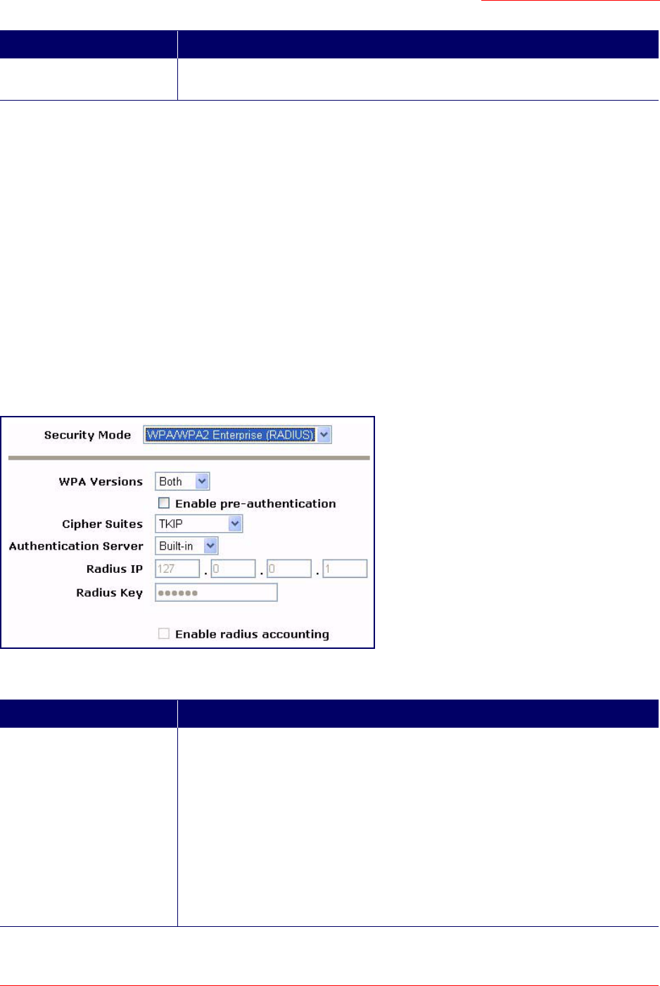
Professional Access Point
Administrator Guide
Security - 107
WPA/WPA2 Enterprise (RADIUS)
Wi-Fi Protected Access 2 (WPA2) with Remote Authentication Dial-In User Service (RADIUS) is an
implementation of the Wi-Fi Alliance IEEE 802.11i standard, which includes Advanced Encryption
Standard (AES), Counter mode/CBC-MAC Protocol (CCMP), and Temporal Key Integrity Protocol (TKIP)
mechanisms. The Enterprise mode requires the use of a RADIUS server to authenticate users, and
configuration of user accounts via the Cluster menu’s User Management page.
This security mode is backward-compatible with wireless clients that support the original WPA.
When configuring WPA2 Enterprise (RADIUS) mode, you can use either the built-in RADIUS server or an
external RADIUS server that you provide. The Professional Access Point built-in RADIUS server supports
Protected EAP (PEAP) and MSCHAP V2.
If you select WPA/WPA2 Enterprise (RADIUS) Security Mode, you must provide the following:
Key The Pre-shared Key is the shared secret key for WPA-PSK. Enter a string of at
least 8 characters to a maximum of 63 characters.
Field Description
WPA Versions Select the types of clients you want to support:
•WPA—
If all clients on the network support the original
WPA,
but none support the newer
WPA2
, then select
WPA
•WPA2—
If all clients on the network support
WPA2
,
USRobotics
suggests using
WPA2
,
which provides the best security per the
IEEE
802.11i
standard.
•Both—
If you have a mix of clients, some of which support
WPA2
and others which sup-
port only the original
WPA
, select
Both
. This option lets both WPA and WPA2 clients
associate and authenticate, but uses the more robust WPA2 for clients who support it.
This WPA configuration allows more interoperability, at the expense of some security.
Field Description

Professional Access Point
Administrator Guide
Security - 108
Enable pre-authentication If for WPA Versions you select WPA2 or Both, you can enable pre-authentication for
WPA2 clients.
Click Enable pre-authentication if you want WPA2 wireless clients to send pre-authen-
tication packet. The pre-authentication information will be relayed from the access
point the client is currently using to the target access point. Enabling this feature
can help speed up authentication for roaming clients who connect to multiple
access points.
This option does not apply if you selected WPA for WPA Versions because the orig-
inal WPA does not support this feature.
Cipher Suites Select the cipher you want to use from the list:
•TKIP—
Temporal Key Integrity Protocol
(TKIP)
provides a more secure encryption
solution than WEP keys. The TKIP process more frequently changes the encryp-
tion key used and better ensures that the same key will not be reused to encrypt
data (a weakness of WEP). TKIP uses a 128-bit temporal key shared by clients
and access points. The temporal key is combined with the client's MAC address
and a 16-octet initialization vector to produce the key that will encrypt the data.
This ensures that each client uses a different key to encrypt data. TKIP uses
RC4 to perform the encryption, which is the same as WEP. But TKIP changes
temporal keys every 10,000 packets and distributes them, thereby greatly
improving the security of the network.
•CCMP (AES)—
Counter mode/CBC-MAC Protocol (CCMP) is an encryption method for
IEEE
802.11i
that uses the
Advanced Encryption Algorithm
(
AES
). It uses a CCM
combined with Cipher Block Chaining Counter mode (CBC-CTR) and Cipher Block Chain-
ing Message Authentication Code (CBC-MAC) for encryption and message integrity.
•Both—The default. When the authentication algorithm is set to Both, both TKIP
and AES clients can associate with the access point.
Clients configured to use WPA
with RADIUS must have one of the following
to be able to associate with the access
point:
• A valid TKIP RADIUS IP address and RADIUS Key
• A valid CCMP (AES) IP address and RADIUS Key
Clients not configured to use WPA with RADIUS will not be able to associate with
access point.
Authentication Server Select one of the following from list:
•Built-in—To use the authentication server provided with the Professional Access
Point. If you choose this option, you do not have to provide the Radius IP and
Radius Key; they are automatically provided.
•External—To use an external authentication server. If you choose this option you
must supply a Radius IP and Radius Key of the server you want to use.
Note: The RADIUS server is identified by its IP address and UDP port numbers for
the different services it provides. On the Professional Access Point, the RADIUS
server User Datagram Protocol (UDP) ports used by the access point are not con-
figurable. The Professional Access Point is hard-coded to use RADIUS server UDP
port 1812 for authentication and port 1813 for accounting.
Field Description

Professional Access Point
Administrator Guide
Security - 109
Updating Settings
To apply your changes, click Update.
Radius IP Enter the Radius IP.
The Radius IP is the IP address of the RADIUS server.
(The Professional Access Point internal authentication server is
127.0.0.1
.)
For information on setting up user accounts, see “User Management” on page 43.
Radius Key Enter the Radius Key.
The Radius Key is the shared secret key for the RADIUS server. The text you enter
will be displayed as "*" characters to prevent others from seeing the RADIUS key
as you type.
(The Professional Access Point internal authentication server key is
secret
.)
This value is never sent over the network.
Enable RADIUS Accounting Click Enable RADIUS Accounting if you want to enforce authentication for WPA clients
with user names and passwords for each client.
See also “User Management” on page 43.
Field Description

Professional Access Point
Administrator Guide
Security - 110

Professional Access Point
Administrator Guide
Guest Login - 111
Guest Login
The Professional Access Point’s Guest Interface features allow you to configure the access point for
controlled guest access to an isolated network. You can configure the same access point to broadcast and
function as two different wireless networks: a secure Internal LAN and a public Guest network.
Guest clients can access the guest network without a user name or password. When guests log in, they
see a guest Welcome screen (also known as a captive portal).
The following sections are included here:
•Understanding the Guest Interface
•Configuring the Guest Interface
•Configuring a Guest Network on a Virtual LAN
•Configuring the Welcome Screen (Captive Portal)
•Using the Guest Network
•Deployment Example
Understanding the Guest Interface
You can define unique parameters for guest connectivity and isolate guest clients from other, more
sensitive areas of the network. No security is provided on the guest network; only None is allowed as the
security mode.
Simultaneously, you can configure a secure internal network (using the same access point as your guest
interface) that provides full access to protected information behind a firewall and requires secure logins or
certificates for access.
Configuring the Guest Interface
To configure the Guest interface on the Professional Access Point, perform these configuration steps:
1. Configure the access point to represent two virtually separate networks as described in the section
“Configuring a Guest Network on a Virtual LAN” on page 112.
2. Set up the guest Welcome screen for the guest captive portal as described in the section “Configuring
Note
The Guest Interface uses the multiple BSSID and Virtual LAN (VLAN) technologies that are built into
the Professional Access Point. The Internal and Guest networks are implemented as multiple BSSIDs
on the same access point, each with different network names (SSIDs) on the Wireless interface and
different VLAN IDs on the Wired interface.

Professional Access Point
Administrator Guide
Guest Login - 112
the Welcome Screen (Captive Portal)” on page 113.
Configuring a Guest Network on a Virtual LAN
To configure Internal and Guest networks on virtual LANs, do the following:
1. Use an Ethernet cable to make a wired connection from the LAN port on the access point to the LAN.
(Make sure this port is configured to handle VLAN tagged packets.)
2. Configure Ethernet (Wired) Settings for Internal and Guest networks on VLANs as described in “Ethernet
(Wired) Settings” on page 79.
(Start by enabling Guest Access and choosing For Internal and Guest access, use VLAN on Ethernet Port as
described in “Specifying a Virtual Guest Network” on page 82.)
3. Provide the radio interface settings and network names (SSIDs) for both Internal and Guest networks
as described in “Wireless Settings” on page 87.
4. Configure the guest splash screen as described below.
Note
Guest Interface settings are not shared among access points across the cluster. These settings must
be configured individually on the Web User Interface pages for each access point. To get to the Web
User Interface for an access point that is a member of the current cluster, click on its IP Address link on
the Cluster menu’s Access Points page of the current access point. For more information about which
settings are shared by the cluster and which are not, see “Which Settings are Shared as Part of the
Cluster Configuration and Which Are Not?” on page 35.
Notes
If you want to configure the Guest and Internal networks on Virtual LAN (VLANs), the switch and
DHCP server you are using must support VLANs.
As a prerequisite step, configure a port on the switch for handling VLAN tagged packets as described
in the IEEE 802.1Q standard.
Guest Welcome Screen settings are shared among access points across the cluster. When you
update these settings for one access point, the configuration will be shared with the other access
points in the cluster. For more information about which settings are shared by the cluster and which
are not, see “Which Settings are Shared as Part of the Cluster Configuration and Which Are Not?” on
page 35.
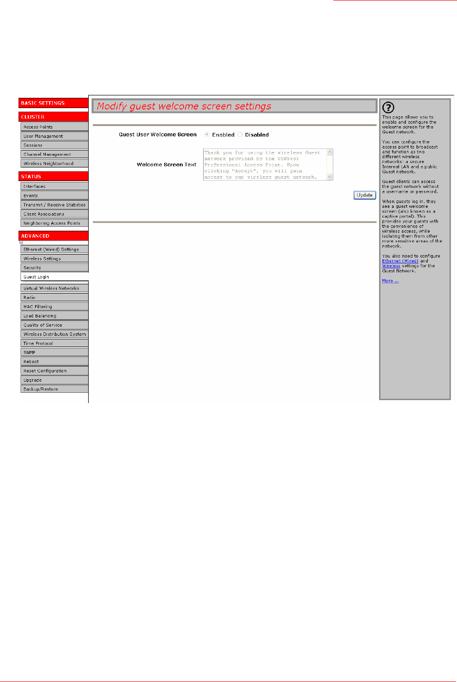
Professional Access Point
Administrator Guide
Guest Login - 113
Configuring the Welcome Screen (Captive Portal)
You can set up or modify the Welcome screen that guest clients see when they open a Web browser or try
to browse the Web. To set up the captive portal, do the following.
1. Click the Advanced menu’s Guest Login tab.
2. Choose Enabled to activate the Welcome screen.
3. In the Welcome Screen Text field, type the text message that you would like guest clients to see on the
captive portal.
4. Click Update to apply the changes.
Using the Guest Network
Once the guest network is configured, a client can access the guest network as follows:
1. A guest client enters an area of coverage and scans for wireless networks.
2. The guest network advertises itself via a Guest SSID or a similar name, depending on how the guest
SSID is specified in the Web User Interface for the Guest interface.
3. The guest chooses Guest SSID.
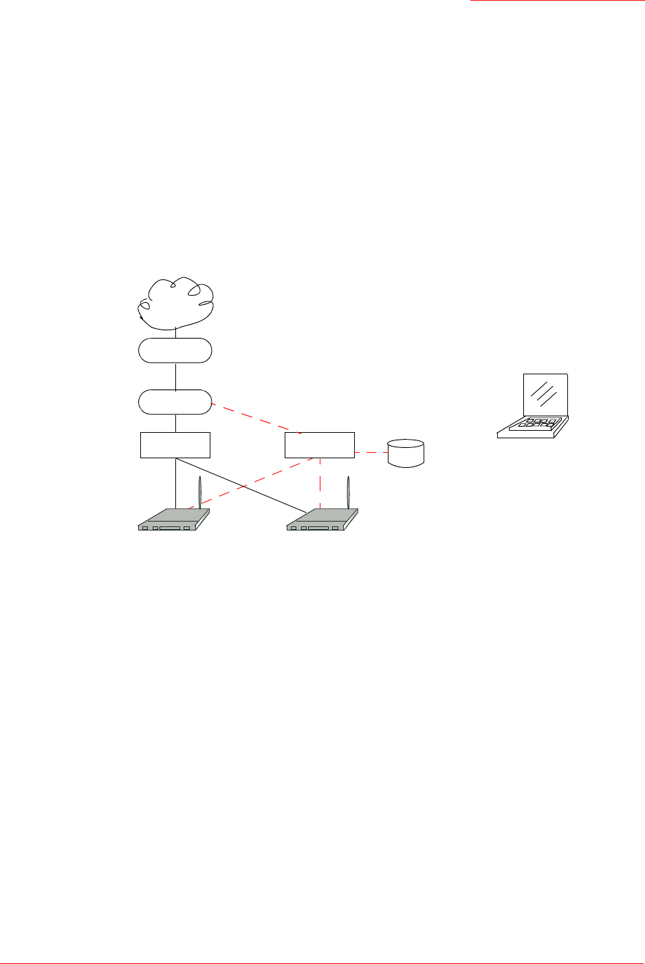
Professional Access Point
Administrator Guide
Guest Login - 114
4. The guest starts a Web browser and receives a Guest Welcome screen.
5. The Guest Welcome Screen provides a button for the guest to click to continue.
6. The guest client is now enabled to use the guest network.
Deployment Example
In the figure below, the dotted red lines indicate dedicated guest connections.
All access points and all connections, including guests, are administered from the same Professional
Access Point Web User Interface.
Access Point Access Point
Firewall
DSL/T1
Switch
Internet
Switch Guest Client Station
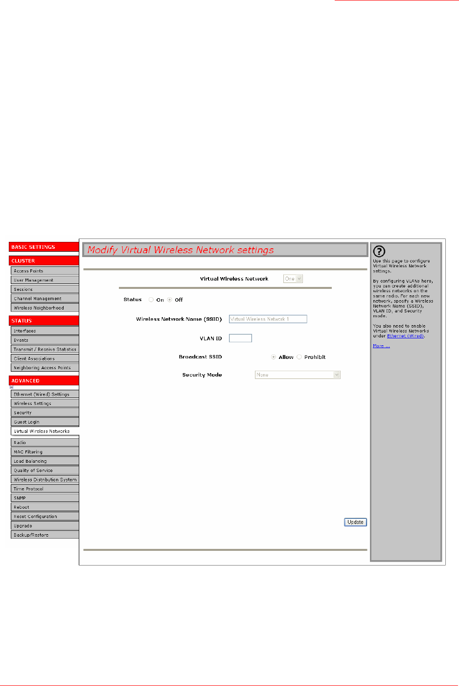
Professional Access Point
Administrator Guide
Virtual Wireless Networks - 115
Virtual Wireless Networks
The following sections describe how to configure multiple wireless networks on Virtual LANs (VLANs):
•Navigating to Virtual Wireless Network Settings
•Configuring VLANs
•Updating Settings
Navigating to Virtual Wireless Network Settings
To set up multiple networks on VLANs, click the Advanced menu’s Virtual Wireless Networks tab, and update
the fields as described below.

Professional Access Point
Administrator Guide
Virtual Wireless Networks - 116
Configuring VLANs
Notes / Cautions
• To configure additional networks on VLANs, you must first enable Virtual Wireless Networks on the
Ethernet (Wired) interface. See “Enabling and Disabling Virtual Wireless Networks on the Access
Point” on page 82.
• If you configure VLANs, you may lose connectivity to the access point. First, be sure to verify that
the switch and DHCP server you are using can support VLANs per the IEEE 802.1Q standard.
After configuring VLANs, physically reconnect the Ethernet cable on the switch to the tagged
packet (VLAN) port. Then, reconnect via the Web User Interface to the new IP address. (If neces-
sary, check with the infrastructure support administrator regarding the VLAN and DHCP configura-
tions.)
Field Description
Virtual Wireless Network Choose one of the following from the drop-down list to identify an additional
network to configure:
•One
•Two
Status You can enable or disable a configured network.
• To enable the specified network, click On.
• To disable the specified network, click Off.
Wireless Network Name (SSID) Enter a name for the wireless network as a character string. This name will
apply to all access points on this network. As you add more access points, they
will share this SSID.
The Service Set Identifier (SSID) is an alphanumeric string of up to 32 charac-
ters
Note: If you are connected as a wireless client to the same access point that
you are administering, resetting the SSID will cause you to lose connectivity to
the access point. You will need to reconnect to the new SSID after you save
this new setting.
VLAN ID Provide a number between 1 and 4094 for the Internal VLAN.
This will cause the access point to send DHCP requests with the VLAN tag.
The switch and the DHCP server must support VLAN IEEE 802.1Q frames.
The access point must be able to reach the DHCP server.
Check with the Administrator regarding the VLAN and DHCP configurations.

Professional Access Point
Administrator Guide
Virtual Wireless Networks - 117
Updating Settings
To apply your changes, click Update.
Broadcast SSID Select the Broadcast SSID setting by clicking the "Allow" or "Prohibit" radio but-
ton.
By default, the access point broadcasts (allows) the Service Set Identifier
(SSID) in its beacon frames.
You can suppress (prohibit) this broadcast to discourage stations from auto-
matically discovering your access point. When the access point’s broadcast
SSID is suppressed, the network name will not be displayed in the List of Avail-
able Networks on a client device. Instead, the client must have the exact net-
work name configured in the supplicant before it will be able to connect.
Note: The Broadcast SSID you set here is specifically for this Virtual Network
(One or Two). Other networks continue to use the security modes already
configured:
• Your original Internal network (configured on Advanced menu’s Ethernet
[Wired] page) uses the Broadcast SSID set on Advanced menu’s Security
page.
• If a Guest network is configured, the Broadcast SSID is always allowed.
Security Mode Select the Security Mode for this VLAN. Select one of the following:
•None
• Static WEP
• IEEE 802.1x
• WPA/WPA2 Personal (PSK)
• WPA/WPA2 Enterprise (RADIUS)
Note: The Security mode you set here is specifically for this Virtual Network
(One or Two). Other networks continue to use the security modes already
configured:
• Your original Internal network uses the Security mode set on the Advanced
menu’s Security page.
• If a Guest network is configured, it always uses None.
For a comparison of the available security modes, see “How Do I Know Which
Security Mode to Use?” on page 91.
Field Description

Professional Access Point
Administrator Guide
Virtual Wireless Networks - 118

Professional Access Point
Administrator Guide
Radio - 119
Radio
The following sections describe how to configure Radio Settings on the Professional Access Point:
•Understanding Radio Settings
•Navigating to Radio Settings
•Configuring Radio Settings
•Updating Settings
Understanding Radio Settings
Radio settings directly control the behaviour of the radio device in the access point and its interaction with
the physical medium, that is, how and what type of electromagnetic waves the access point emits. You can
specify whether the radio is on or off, radio frequency (RF) broadcast channel, beacon interval (amount of
time between access point beacon transmissions), transmit power, IEEE 802.11 mode in which the radio
operates, and so on.
The Professional Access Point can broadcast in the following modes:
• IEEE 802.11b
• IEEE 802.11g
The IEEE mode along with other radio settings are configured as described in “Navigating to Radio
Settings” on page 120 and “Configuring Radio Settings” on page 120.
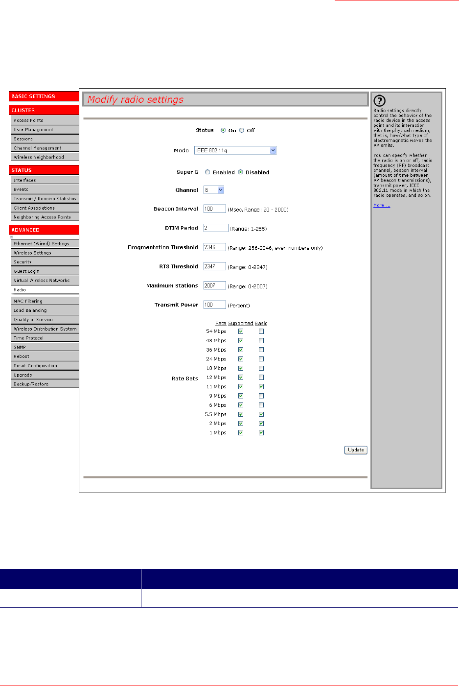
Professional Access Point
Administrator Guide
Radio - 120
Navigating to Radio Settings
To specify radio settings, click the Advanced menu’s Radio tab, and update the fields as described below.
Configuring Radio Settings
Field Description
Status (On/Off) Specify whether you want the radio on or off by clicking On or Off.

Professional Access Point
Administrator Guide
Radio - 121
Mode The Mode defines the Physical Layer (PHY) standard being used by the radio.
Select one of these modes:
• IEEE 802.11b
•IEEE 802.11g (the default). This mode allows both 802.11b and 802.11g cli-
ents to connect to the access point. To enable 802.11g clients only and
deny acces to 802.11b clients, select a Basic rate that is not supported by
802.11b, such as 6Mbps. Basic rate options appear at the bottom of the
Radio tab.
Super G Enabling Super G provides better performance by increasing radio throughput
for a radio mode. Keep in mind that with Super G enabled the access point
transmissions will consume more bandwidth.
• To enable Super G click Enabled.
• To disable Super G click Disabled.
Channel The Channel defines the portion of the radio spectrum that the radio uses for
transmitting and receiving. The range of channels and the default channel are
determined by the Mode of the radio interface.
For most Modes, the default is Auto. Auto is the recommended mode because
it automatically detects the best channel choices based on signal strength, traf-
fic loads, and so on.
Beacon Interval The Beacon Interval value is set in milliseconds. Enter a value within the range
20–2000.
Beacon frames are transmitted by an access point at regular intervals to
announce the existence of the wireless network. The default behaviour is to
send a beacon frame once every 100 milliseconds (or 10 per second).
DTIM Period Specify a DTIM period within the range 1–255.
The Delivery Traffic Information Map (DTIM) message is an element included
in some Beacon frames. It indicates which clients, currently sleeping in low-
power mode, have data buffered on the access point awaiting pickup.
The DTIM period you specify here indicates how often the clients served by
this access point will check for buffered data still on the access point awaiting
pickup.
The measurement is the count of beacons. For example, if you set the DTIM
period to 1, clients will check for buffered data on the access point at every
beacon. If you set this to 10, clients will check at every 10th beacon.
Field Description

Professional Access Point
Administrator Guide
Radio - 122
Fragmentation Threshold Specify a number within the range 256–2,346 to set the frame size threshold in
bytes.
The fragmentation threshold is a way of limiting the size of packets (frames)
transmitted over the network. If a packet exceeds the fragmentation threshold
set here, the fragmentation function will be activated and the packet will be
sent as multiple 802.11 frames.
If the packet being transmitted is equal to or less than the threshold, fragmen-
tation will not be used.
Setting the threshold to the largest value (2,346 bytes) effectively disables frag-
mentation.
Fragmentation involves more overhead both because of the extra work of
dividing up and reassembling of frames it requires, and because it increases
message traffic on the network. However, fragmentation can help improve net-
work performance and reliability if properly configured.
Sending smaller frames (by using lower fragmentation threshold) may help
with some interference problems; for example, with microwave ovens.
By default, fragmentation is off. USRobotics recommends not using fragmen-
tation unless you suspect radio interference. The additional headers applied to
each fragment increase the overhead on the network and can greatly reduce
throughput.
RTS Threshold Specify an RTS Threshold value within the range 0–2347.
The RTS threshold specifies the packet size of a request to send (RTS) trans-
mission. This helps control traffic flow through the access point, especially one
with a lot of clients.
If you specify a low threshold value, RTS packets will be sent more frequently.
This will consume more bandwidth and reduce the throughput of the packet.
On the other hand, sending more RTS packets can help the network recover
from interference or collisions which might occur on a busy network, or on a
network experiencing electromagnetic interference.
Maximum Stations Enter a value within the range 0–2007.
Specify the maximum number of stations allowed to access this access point at
any one time.
Field Description

Professional Access Point
Administrator Guide
Radio - 123
Updating Settings
To apply your changes, click Update.
Transmit Power Provide a percentage value to set the transmit power for this access point.
The default is to have the access point transmit using 100 percent of its power.
Recommendations:
• For most cases, USRobotics recommends using the default and having the
transmit power set to 100 percent. This is more cost-efficient because it
gives the access point a maximum broadcast range and reduces the
number of APs needed.
• To increase capacity of the network, place APs closer together and reduce
the value of the transmit power. This will help reduce overlap and interfer-
ence among APs. A lower transmit power setting can also keep your net-
work more secure because weaker wireless signals are less likely to
propagate outside of the physical location of your network.
Rate Sets Select the transmission rate sets that you want the access point to support and
the basic rate sets you want the access point to advertise.
Rates are expressed in megabits per second.
•Supported Rate Sets indicate rates that the access point supports. You can
select multiple rates. The access point will automatically choose the most
efficient rate based on factors like error rates and distance of clients from
the access point.
•Basic Rate Sets indicate rates that the access point will advertise to the net-
work for the purposes of setting up communication with other APs and cli-
ents on the network. It is generally more efficient to have an access point
broadcast a subset of its supported rate sets.
The highest basic rate selected is also the access point’s multicast rate. To
transmit multicast packets at a higher rate than the default of 11Mbps, select
a higher Basic Rate.
Field Description

Professional Access Point
Administrator Guide
Radio - 124

Professional Access Point
Administrator Guide
MAC Filtering - 125
MAC Filtering
A Media Access Control (MAC) address is a hardware address that uniquely identifies each node of a
network. All IEEE 802 network devices share a common 48-bit MAC address format, usually displayed as
a string of 12 hexadecimal digits separated by colons, for example
FE:DC:BA:09:87:65
.
Each wireless network interface card (NIC) used by a wireless client has a unique MAC address.
You can control client access to your wireless network by switching on MAC Filtering and specifying a list
of approved MAC addresses. When MAC Filtering is on, only clients with approved MAC addresses can
access the network.
The following sections describe how to use MAC address filtering on the Professional Access Point:
•Navigating to MAC Filtering Settings
•Using MAC Filtering
•Updating Settings
Navigating to MAC Filtering Settings
To enable filtering by MAC address, click the Advanced menu’s MAC Filtering tab, and update the fields as
described below.
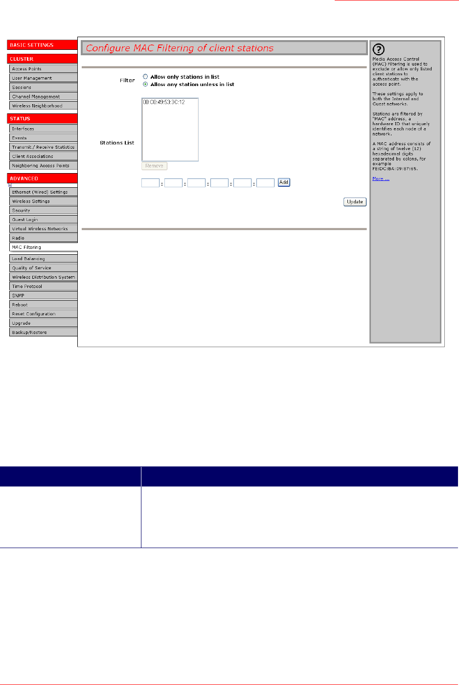
Professional Access Point
Administrator Guide
MAC Filtering - 126
Using MAC Filtering
This page allows you to control access to Professional Access Point based on Media Access Control
(MAC) addresses. You can choose to allow access by listed MAC addresses or prevent access by listed
MAC addresses.
For the Guest interface, MAC Filtering settings apply to both BSSes.
Field Description
Filter To set the MAC Address Filter, select one of the following options:
• Allow only stations in the list
• Allow any station unless in list

Professional Access Point
Administrator Guide
MAC Filtering - 127
Updating Settings
To apply your changes, click Update.
Stations List To add a MAC Address to the Stations List, type the 48-bit MAC address into
the lower text boxes, then click Add.
The MAC Address is added to the Stations List.
To remove a MAC Address from the Stations List, select its 48-bit MAC
address, then click Remove.
The stations in the list will be either allowed to access or prevented from
accessing the access point depending on the value that you chose for Filter.
Field Description

Professional Access Point
Administrator Guide
MAC Filtering - 128

Professional Access Point
Administrator Guide
Load Balancing - 129
Load Balancing
The Professional Access Point allows you to balance the distribution of wireless client connections across
multiple access points. Using load balancing, you can prevent the performance degradation that results
when a single access point handles a disproportionate share of the wireless traffic.
The following sections describe how to configure Load Balancing on your wireless network:
•Understanding Load Balancing
•Identifying the Imbalance: Overworked or Under-utilized Access Points
•Specifying Limits for Utilization and Client Associations
•Load Balancing and QoS
•Navigating to Load Balancing Settings
•Configuring Load Balancing
•Updating Settings
Understanding Load Balancing
Like most configuration settings on the Professional Access Point, load balancing settings are shared
among clustered access points.
Identifying the Imbalance: Overworked or Under-utilized Access Points
Comparison of Sessions data for multiple access points allows you to identify an access point that is
consistently handling a disproportionately large percentage of wireless traffic. This can happen when
location placement or other factors cause one access point to transmit the strongest signal to a majority of
clients on a network. By default, that access point will receive most of client requests while the other
access points stay idle much of the time.
Imbalances in distribution of wireless traffic across access points will be evident in Sessions statistics,
which will show higher utilization rates on overworked APs and higher Idle times on under-utilized APs. An
access point that is handling a disproportionate amount of traffic might also show slower data rates or
lower transmit and receive rates due to the overload.
Specifying Limits for Utilization and Client Associations
You can correct for imbalances in network access point utilization by enabling load balancing and setting
limits on utilization rates and number of client associations allowed per access point.
Note
In some cases you might want to set limits for only one access point that is consistently over-utilized.
You can apply unique settings to an access point if it is operating in standalone mode. (See “Under-
standing Clustering” on page 34 and “Navigating to Access Points Management” on page 34.)
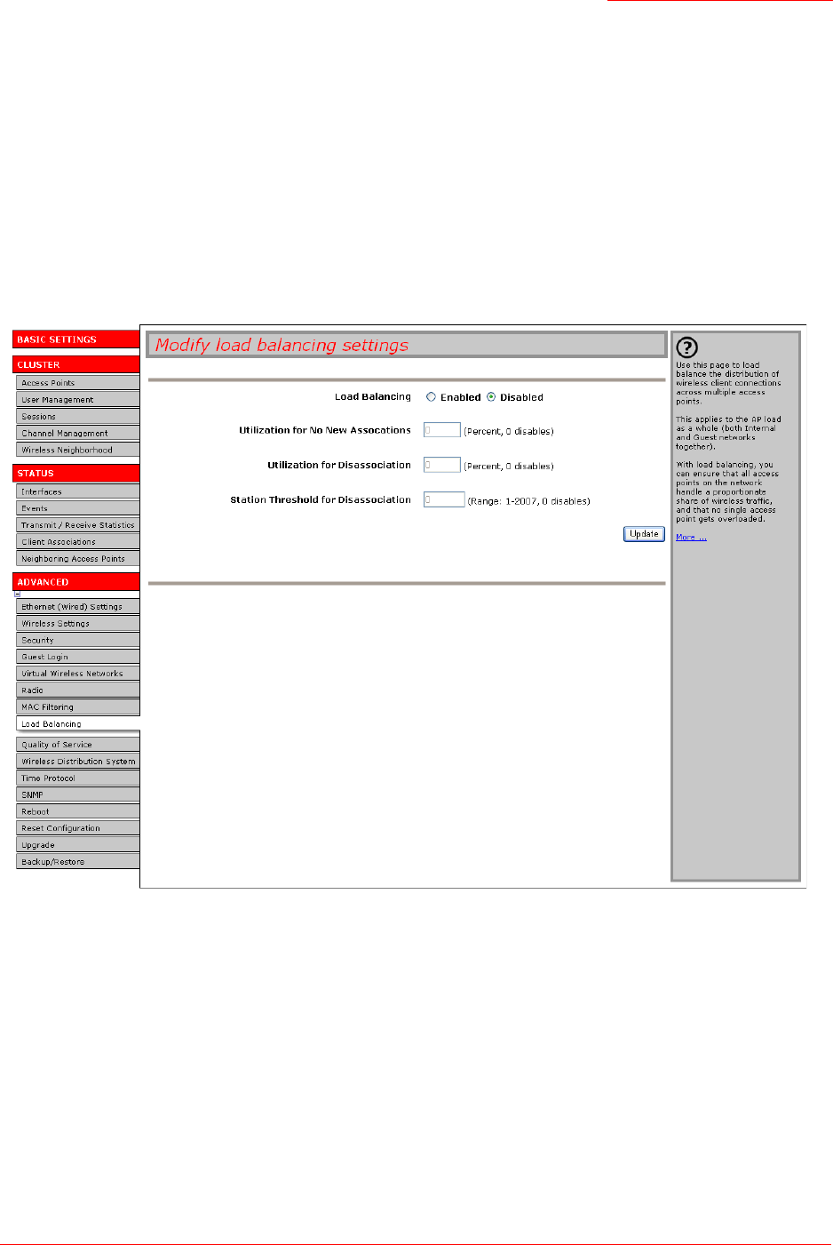
Professional Access Point
Administrator Guide
Load Balancing - 130
Load Balancing and QoS
Load balancing contributes to Quality of Service (QoS) for Voice Over IP (VoIP) and other such time-
sensitive applications competing for bandwidth and timely access to the air waves on a wireless network.
For more information about configuring your network for QoS, see “Quality of Service” on page 133.
Navigating to Load Balancing Settings
In the Web User Interface, click the Advanced menu’s Load Balancing tab, and update the fields as
described in the next section.
Configuring Load Balancing
To configure load balancing, enable Load Balancing and set limits and behaviour to be triggered by a

Professional Access Point
Administrator Guide
Load Balancing - 131
specified utilization rate of the access point.
Note
• To view the current Utilization Rates for access points, click the Cluster menu’s Sessions tab. (See
“Sessions” on page 49.)
• When clients are disassociated from an access point, the network will provide continuous service if
another access point is within range of the client. Clients should automatically retry the access
points to which they were originally connected and then try other APs on the subnet. Clients who
are disassociated from one access point will experience a seamless transition to another access
point on the same subnet.
• Load Balancing settings apply to the access point load as a whole. When Guest access is ena-
bled, the settings apply to both Internal and Guest networks together.
Field Description
Load Balancing To enable load balancing on this access point, click Enable.
To disable load balancing on this access point, click Disable.
Utilization for No New Associations Utilization rate limits relate to wireless bandwidth utilization.
Provide a bandwidth utilization rate percentage limit for this access point to
indicate when to stop accepting new client associations.
When the utilization rate for this access point exceeds the specified limit, no
new client associations will be allowed on this access point.
If you specify 0 in this field, all new associations will be allowed regardless of
the utilization rate.
Utilization for Disassociation Utilization rate limits relate to wireless bandwidth utilization.
Provide a bandwidth utilization rate percentage limit for this access point to
indicate when to disassociate current clients.
When the utilization rate exceeds the specified limit, a client currently associ-
ated with this access point will be disconnected.
If you specify 0 in this field, current clients will never be disconnected regard-
less of the utilization rate.
Stations Threshold for Disassocia-
tion
Specify the number of clients that you want as a stations threshold for disasso-
ciation. If the number of clients associated with the access point at any one
time is equal to or less than the number you specify here, no client will be dis-
associated regardless of the Utilization for Disassociation value.
Theoretically, the maximum number of clients allowed is 2007.
USRobotics recommends setting the maximum to between 30 and 50
clients . This allows for a workable load on the access point, given that
bandwidth is shared among the access point clients.

Professional Access Point
Administrator Guide
Load Balancing - 132
Updating Settings
To apply your changes, click Update Settings.

Professional Access Point
Administrator Guide
Quality of Service - 133
Quality of Service
Quality of Service (QoS) provides you with the ability to specify parameters on multiple queues for
increased throughput and better performance of differentiated wireless traffic like Voice-over-IP (VoIP);
other types of audio, video, and streaming media; and traditional IP data.
The following sections describe how to configure Quality of Service queues on the Professional Access
Point:
•Understanding QoS
•QoS and Load Balancing
•802.11e and WMM Standards Support
•QoS Queues and Parameters to Coordinate Traffic Flow
•Navigating to QoS Settings
•Configuring QoS Queues
•Configuring AP EDCA Parameters
•Enabling/Disabling Wi-Fi Multimedia
•Configuring Station EDCA Parameters
•Updating Settings
Understanding QoS
A primary factor that affects QoS is network congestion due to an increased number of clients attempting
to access the air waves and higher traffic volume competing for bandwidth during a busy time of day. The
most noticeable degradation in service on a busy, overloaded network will be evident in time-sensitive
applications like video, Voice-over-IP (VoIP), and streaming media.
Unlike typical data files, which are less affected by variability in QoS, video, VoIP and streaming media
must be sent in a specific order at a consistent rate and with minimum delay between Packet
transmissions. If the quality of service is compromised, the audio or video will be distorted.
QoS and Load Balancing
By using a combination of load balancing (see “Load Balancing” on page 129) and QoS techniques, you
can provide a high quality of service for time-sensitive applications, even on a busy network. Load
balancing is a way of better distributing the traffic volume across access points. QoS is a means of
allocating bandwidth and network access based on transmission priorities for different types of wireless
traffic within a single access point.
802.11e and WMM Standards Support
QoS describes a range of technologies for controlling data streams on shared network connections. The

Professional Access Point
Administrator Guide
Quality of Service - 134
IEEE 802.11e task group is in the process of defining a QoS standard for transmission quality and
availability of service on wireless networks. QoS is designed to provide better network service by
minimizing network congestion; limiting Jitter, Latency, and Packet Loss; supporting dedicated bandwidth
for time-sensitive or mission critical applications; and prioritising wireless traffic for channel access.
As with all IEEE 802.11 working group standards, the goal is to provide a standard way of implementing
QoS features so that components from different companies are interoperable.
The Professional Access Point provides QoS based on the Wireless Multimedia (WMM) specification and
Wireless Multimedia (WMM) standards, which are implementations of a subset of 802.11e features.
Both access points and wireless clients can be WMM-enabled.
QoS Queues and Parameters to Coordinate Traffic Flow
Configuring QoS options on the Professional Access Point consists of setting parameters on existing
queues for different types of wireless traffic. You can configure different minimum and maximum wait times
for the transmission of packets in each queue based on the requirements of the media being sent. Queues
automatically provide minimum transmission delay for voice, video, multimedia, and mission-critical
applications and rely on best-effort parameters for traditional IP data.
For example, time-sensitive voice, video, and multimedia are given effectively higher priority for
transmission (lower wait times for channel access), while other applications and traditional IP data—which
are less time-sensitive but often more data-intensive—are expected to tolerate longer wait times.
The Professional Access Point implementation of QoS is based on the IEEE Wireless Multimedia (WMM)
standard. A Linux-based queuing class is used to tag packets and establish multiple queues. The queues
provided offer built-in prioritisation and routing based on the type of data being transmitted.
The Web User Interface provides a way for you to configure parameters on the queues.
QoS Queues and Type of Service (ToS) on Packets
QoS on the Professional Access Point uses WMM information in the IP packet header related to Type of
Service (To S). Every IP packet sent over the network includes a ToS field in the header that indicates how
the data is to be prioritised and transmitted over the network. The ToS field consists of a 3- to 7-bit value
with each bit representing a different aspect or degree of priority for this data as well as other meta-
information (low delay, high throughput, high reliability, low cost, and so on).
For example, the ToS for FTP data packets is likely to be set for maximum throughput since the critical
consideration for FTP is the ability to transmit bulk data. Interactive feedback is a benefit in this situation
but certainly is less critical than the FTP data itself. VoIP data packets are set for minimum delay because
time is a critical factor in quality and performance for that type of data.
The access point examines the ToS field in the header of each packet that passes through the access
point. Based on the value in a packet’s ToS field, the access point prioritises the packet for transmission by
assigning it to one of the queues. This process occurs automatically, regardless of whether you
deliberately configure QoS or not.
A different type of data is associated with each queue. The queue and associated priorities and
parameters for transmission are as follows:
•Data 0 (Voice). Highest priority queue, minimum delay. Time-sensitive data such as Voice over IP (VoIP)

Professional Access Point
Administrator Guide
Quality of Service - 135
is automatically sent to this queue.
•Data 1 (Video). High priority queue, minimum delay. Time-sensitive data such as Video and other
streaming media are automatically sent to this queue.
•Data 2 (Best Effort). Medium priority queue, medium throughput and delay. Most traditional IP data is
sent to this queue.
•Data 3 (Background). Lowest priority queue, high throughput. Bulk data that requires maximum through-
put and is not time-sensitive is sent to this queue (FTP data, for example).
Packets in a higher priority queue will be transmitted before packets in a lower priority queue. Interactive
data in the queues labeled "Data 0" and "Data 1" is always sent first, best effort data in "Data 2" is sent
next, and Background (bulk) data in "Data 3" is sent last. Each lower-priority queue (class of traffic) gets
bandwidth that is left over after the higher classes of traffic have been sent. At an extreme end if you have
enough interactive data to keep the access point busy all the time, low priority traffic would never get sent.
Using the QoS settings in the Web User Interface, you can configure Enhanced Distributed Channel
Access (EDCA) parameters that determine how each queue is treated when it is sent by the access point
to the client or by the client to the access point.
EDCF Control of Data Frames and Arbitration Interframe Spaces
Data is transmitted over 802.11 wireless networks in frames. A Frame consists of a discrete portion of data
along with descriptive meta-information packaged for transmission on a wireless network.
Each frame includes a source and destination MAC address, a control field with protocol version, frame
type, frame sequence number, frame body (with the actual information to be transmitted) and frame check
sequence for error detection.
The 802.11 standard defines various frame types for management and control of the wireless
infrastructure, and for data transmission. 802.11 frame types are (1) management frames, (2) control
frames, and (3) data frames. Management and control frames, which manage and control the availability of
the wireless infrastructure, automatically have higher priority for transmission.
Note
Wireless traffic travels:
• Downstream from the access point to the client
• Upstream from client to access point
• Upstream from access point to network
• Downstream from network to access point
With WMM enabled, QoS settings on the Professional Access Point affect the first two of these; down-
stream traffic flowing from the access point to client (access point EDCA parameters) and the
upstream traffic flowing from the client to the access point (station EDCA parameters).
With WMM disabled, you can still set some parameters on the downstream traffic flowing from the
access point to the client (access point EDCA parameters).
Traffic flow to and from the network is not under control of the QoS settings on the access point.
Note
A Frame is similar in concept to a Packet, the difference being that a packet operates on the Network
layer (layer 3 in the OSI model) whereas a frame operates on the Data-Link layer (layer 2 in the OSI
model).

Professional Access Point
Administrator Guide
Quality of Service - 136
802.11e uses interframe spaces to regulate which frames get access to available channels and to
coordinate wait times for transmission of different types of data.
Management and control frames wait a minimum amount of time for transmission: they wait a short
interframe space (SIF). These wait times are built into 802.11 as infrastructure support and are not
configurable.
The Professional Access Point supports the Enhanced Distribution Coordination Function (EDCF) as
defined by the 802.11e standard. EDCF, which is an enhancement to the DCF standard and is based on
CSMA/CA protocol, defines the interframe space (IFS) between data frames. Data frames wait for an
amount of time defined as the arbitration interframe space (AIFS) before transmitting. The AIFS parameter
is configurable.
(Note that sending data frames in AIFS allows higher priority management and control frames to be sent in
SIFs first.)
The AIFS ensures that multiple access points do not try to send data at the same time but instead wait until
a channel is free.
Random Backoff and Minimum / Maximum Contention Windows
If an access point detects that the medium is in use, it uses the DCF random backoff timer to determine the
amount of time to wait before attempting to access a given channel again. Each access point waits a
random period of time between retries. The wait time (initially a random value within a range specified as
the Minimum Contention Window) increases exponentially up to a specified limit (Maximum Contention
Window). The random delay avoids most of the collisions that would occur if multiple APs got access to the
medium at the same time and tried to transmit data simultaneously. The greater the number of active users
on a network, the more significant the performance gains of the backoff timer will be due to the reduction in
the number of collisions and retransmissions.
The random backoff used by the access point is a configurable parameter. To describe the random delay,
a Minimum Contention Window (cwMin) and a Maximum Contention Window (cwMax) is defined.
• The value specified for the Minimum Contention Window is the upper limit of a range for the initial ran-
dom backoff wait time. The number used in the random backoff is initially a random number between 0
and the number defined for the Minimum Contention Window.
• If the first random backoff time ends before successful transmission of the data frame, the access point
increments a retry counter, and doubles the value of the random backoff window. The value specified
in the Maximum Contention Window is the upper limit for this doubling of the random backoff. This
doubling continues until either the data frame is sent or the Maximum Contention Window size is
reached.
15 10 15 20
Backoff time
in milliseconds
Backoff2 = MinCW doubled
Initial Backoff = random number in
Backoff 4 = re-doubled
range of MinCW
25
Doubling continues on each try until MaxCW is reached
at which point this wait time is used on retries
until data is sent or until retries limit is reached
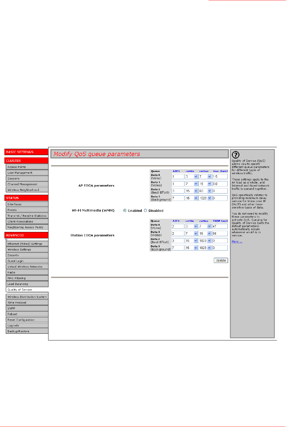
Professional Access Point
Administrator Guide
Quality of Service - 137
Packet Bursting for Better Performance
The Professional Access Point includes 802.11e based packet bursting technology that increases data
throughput and speed of transmission over the wireless network. Packet bursting enables the transmission
of multiple packets without the extra overhead of header information. The effect of this is to increase
network speed and data throughput. The size of packet bursts allowed (maximum burst length) is a
configurable parameter.
Transmission Opportunity (TXOP) Interval for Client Stations
The Transmission Opportunity (TXOP) is an interval of time when a Wi-Fi Multimedia (WMM) client station
has the right to initiate transmissions onto the wireless medium (WM).
Navigating to QoS Settings
To set up queues for QoS, click the Advanced menu’s Quality of Service tab, and configure settings as
described below.
Configuring QoS Queues
Configuring Quality of Service (QoS) on the Professional Access Point consists of setting parameters on
existing queues for different types of wireless traffic, and effectively specifying minimum and maximum
wait times (via Contention Windows) for transmission. The settings described here apply to data

Professional Access Point
Administrator Guide
Quality of Service - 138
transmission behaviour on the access point only, not to that of the client stations.
Configuring Quality of Service includes:
•Configuring AP EDCA Parameters
•Enabling/Disabling Wi-Fi Multimedia
•Updating Settings
Configuring AP EDCA Parameters
AP Enhanced Distributed Channel Access (EDCA) Parameters affect traffic flowing from the access point
to the client station.
Notes
• For the Guest interface, QoS queue settings apply to the access point load as a whole (both
BSSes together).
• Internal and Guest network traffic is always queued together.
Field Description
Queue Queues are defined for different types of data transmitted from the access
point-to the client station:
Data 0 (Voice)
Highest priority queue, minimum delay. Time-sensitive data such as VoIP and
streaming media are automatically sent to this queue.
Data 1(Video)
Highest priority queue, minimum delay. Time-sensitive video data is
automatically sent to this queue.
Data 2 (best effort)
Medium priority queue, medium throughput and delay. Most traditional IP data
is sent to this queue.
Data 3 (Background)
Lowest priority queue, high throughput. Bulk data that requires maximum
throughput and is not time-sensitive is sent to this queue (FTP data, for exam-
ple).
For more information, see “QoS Queues and Parameters to Coordinate Traffic
Flow” on page 134.
AIFS
(Inter-Frame Space)
The Arbitration Inter-Frame Spacing (AIFS) specifies a wait time in milliseconds
for data frames.
Valid values for AIFS are 1 through 255.
For more information, see “EDCF Control of Data Frames and Arbitration Inter-
frame Spaces” on page 135.

Professional Access Point
Administrator Guide
Quality of Service - 139
Enabling/Disabling Wi-Fi Multimedia
By default, Wi-Fi MultiMedia (WMM) is enabled on the access point. With WMM enabled, QoS prioritisation
and coordination of wireless medium access is on. With WMM enabled, QoS settings on the Professional
Access Point control downstream traffic flowing from the access point to client station (access point EDCA
parameters) and the upstream traffic flowing from the station to the access point (station EDCA
parameters).
Disabling WMM will deactivate QoS control of station EDCA parameters on upstream traffic flowing from
the station to the access point
With WMM disabled, you can still set some parameters on the downstream traffic flowing from the access
cwMin
(Minimum Contention Window)
This parameter is input to the algorithm that determines the initial random
backoff wait time for retry of a transmission.
Select a value from the list. The value selected for cwMin is the upper limit, in
milliseconds, of a range from which the initial random backoff wait time is
determined.
The first random number generated will be a number between 0 and the
number specified in cwMin.
If the first random backoff wait time expires before the data frame is sent, a
retry counter is incremented and the random backoff value (window) is dou-
bled. Doubling will continue until the size of the random backoff value reaches
the number defined in the Maximum Contention Window.
For more information, see “Random Backoff and Minimum / Maximum Conten-
tion Windows” on page 136.
cwMax
(Maximum Contention Window)
Select a value that is higher than cwMin.
The value specified for cwMax is the upper limit, in milliseconds, for the dou-
bling of the random backoff value. This doubling continues until either the data
frame is sent or the Maximum Contention Window size is reached.
Once the Maximum Contention Window size is reached, retries will continue
until a maximum number of retries allowed is reached.
For more information, see “Random Backoff and Minimum / Maximum Conten-
tion Windows” on page 136.
Max. Burst
(Maximum Burst Length)
AP EDCA Parameter Only. The Max. Burst Length applies only to traffic flowing
from the access point to the client station.
This value specifies, in milliseconds, the Maximum Burst Length allowed for
packet bursts on the wireless network. A packet burst is a collection of multiple
frames transmitted without header information. The decreased overhead
results in higher throughput and better performance.
Valid values for maximum burst length are 0.0 through 999.9.
For more information, see “Packet Bursting for Better Performance” on
page 137.
Field Description

Professional Access Point
Administrator Guide
Quality of Service - 140
point to the client station (access point EDCA parameters).
• To disable WMM extensions, click Disabled.
• To enable WMM extensions, click Enabled.
Configuring Station EDCA Parameters
Station Enhanced Distributed Channel Access (EDCA) Parameters affect traffic flowing from the client
station to the access point.
Field Description
Queue Queues are defined for different types of data transmitted from the client sta-
tion to the access point:
Data 0 (Voice)
Highest priority queue, minimum delay. Time-sensitive data such as VoIP and
streaming media are automatically sent to this queue.
Data 1(Video)
Highest priority queue, minimum delay. Time-sensitive video data is
automatically sent to this queue.
Data 2 (best effort)
Medium priority queue, medium throughput and delay. Most traditional IP data
is sent to this queue.
Data 3 (Background)
Lowest priority queue, high throughput. Bulk data that requires maximum
throughput and is not time-sensitive is sent to this queue (FTP data, for exam-
ple).
For more information, see “QoS Queues and Parameters to Coordinate Traffic
Flow” on page 134.
AIFS
(Inter-Frame Space)
The Arbitration Inter-Frame Spacing (AIFS) specifies a wait time (in millisec-
onds) for data frames.
For more information, see “EDCF Control of Data Frames and Arbitration Inter-
frame Spaces” on page 135.

Professional Access Point
Administrator Guide
Quality of Service - 141
Updating Settings
To apply your changes, click Update.
cwMin
(Minimum Contention Window)
This parameter is input to the algorithm that determines the initial random
backoff wait time (window) for retry of a transmission.
The value specified here in the Minimum Contention Window is the upper limit
(in milliseconds) of a range from which the initial random backoff wait time is
determined.
The first random number generated will be a number between 0 and the
number specified here.
If the first random backoff wait time expires before the data frame is sent, a
retry counter is incremented and the random backoff value (window) is dou-
bled. Doubling will continue until the size of the random backoff value reaches
the number defined in the Maximum Contention Window.
For more information, see “Random Backoff and Minimum / Maximum Conten-
tion Windows” on page 136.
cwMax
(Maximum Contention Window)
The value specified here in the Maximum Contention Window is the upper limit
(in milliseconds) for the doubling of the random backoff value. This doubling
continues until either the data frame is sent or the Maximum Contention Win-
dow size is reached.
Once the Maximum Contention Window size is reached, retries will continue
until a maximum number of retries allowed is reached.
For more information, see “Random Backoff and Minimum / Maximum Conten-
tion Windows” on page 136.
TXOP Limit
(Transmission Opportunity Limit)
Station EDCA Parameter Only (The TXOP Limit applies only to traffic flowing
from the client station to the access point.)
The Transmission Opportunity (TXOP) is an interval of time when a WME
client station has the right to initiate transmissions onto the wireless medium
(WM).
This value specifies (in milliseconds) the Transmission Opportunity (TXOP) for
client stations; that is, the interval of time when a WMM client station has the
right to initiate transmissions on the wireless network.
Field Description

Professional Access Point
Administrator Guide
Quality of Service - 142

Professional Access Point
Administrator Guide
Wireless Distribution System - 143
Wireless Distribution System
The Professional Access Point lets you connect multiple access points using a Wireless Distribution
System (WDS). WDS allows access points to communicate with one another wirelessly in a standardized
way. This capability is critical to providing a seamless experience for roaming clients and for managing
multiple wireless networks. It can also simplify the network infrastructure by reducing the amount of cabling
required.
The following sections describe how to configure the WDS on the Professional Access Point:
•Understanding the Wireless Distribution System
•Using WDS to Bridge Distant Wired LANs
•Using WDS to Extend the Network Beyond the Wired Coverage Area
•Backup Links and Unwanted Loops in WDS Bridges
•Security Considerations Related to WDS Bridges
•Navigating to WDS Settings
•Configuring WDS Settings
•Example of Configuring a WDS Link
•Updating Settings
Understanding the Wireless Distribution System
A Wireless Distribution System (WDS) is an 802.11f technology that wirelessly connects access points,
known as Basic Service Sets (BSS), to form what is known as an Extended Service Set (ESS).
Using WDS to Bridge Distant Wired LANs
In an ESS—a network of multiple access points—each access point serves part of an area that is too large
for a single access point to cover. You can use WDS to bridge distant Ethernets to create a single LAN.
For example, suppose that you have one access point that is connected to the network by Ethernet and
serving multiple clients in the Conference Room (LAN Segment 1), and another Ethernet-wired access
point serving stations in the West Wing offices (LAN Segment 2). You can bridge the Conference Room
Note
A BSS generally equates to an access point deployed as a single-access-point wireless network. In
cases where multi-BSSID features make a single access point look like two or more access points to
the network, the access point has multiple unique BSSIDs.
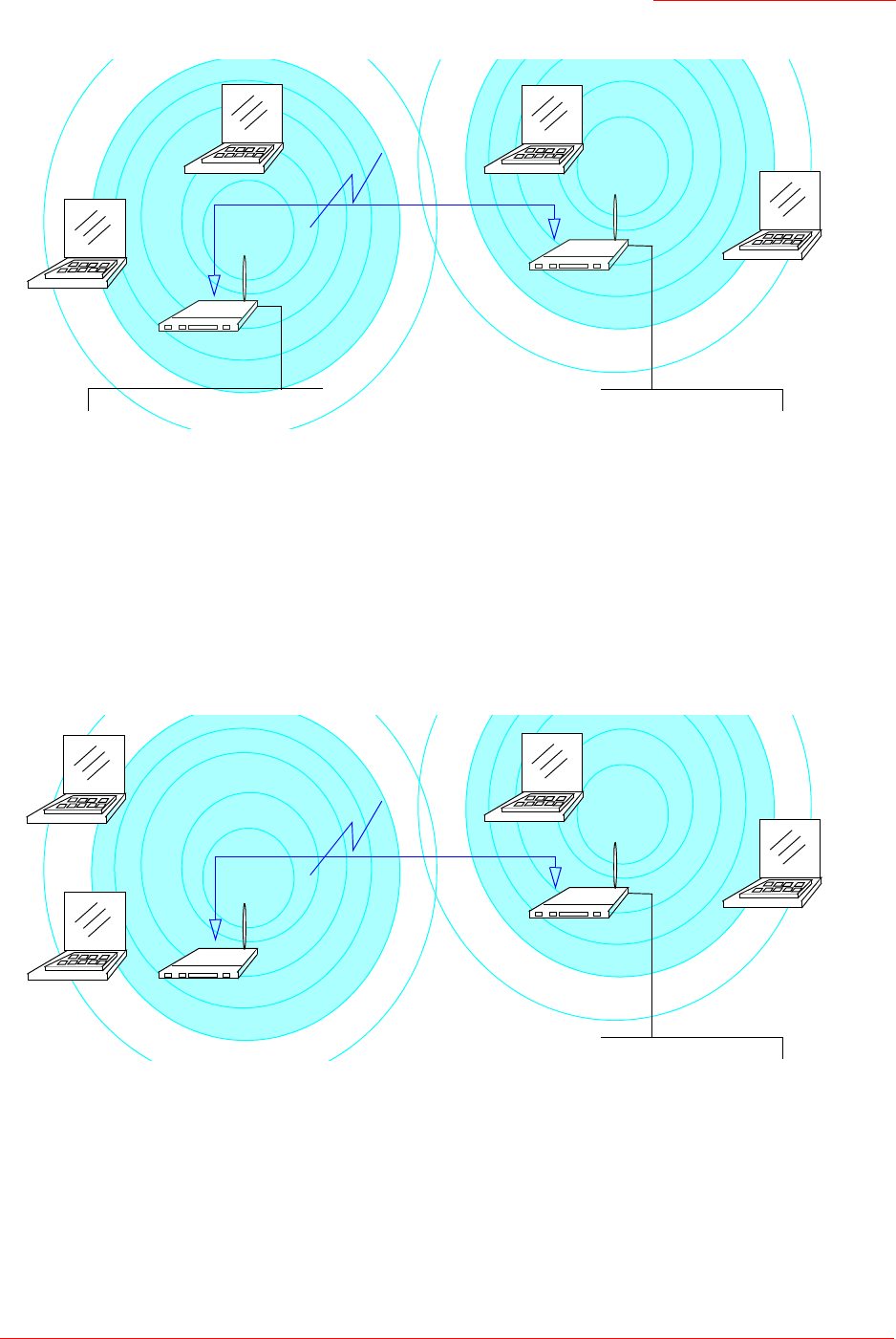
Professional Access Point
Administrator Guide
Wireless Distribution System - 144
and West Wing access points with a WDS link to create a single network for clients in both areas.
Using WDS to Extend the Network Beyond the Wired Coverage Area
An ESS can extend the reach of the network into areas where cabling would be difficult, costly, or
inefficient.
For example, suppose you have an access point which is connected to the network by Ethernet and
serving multiple clients in one area ("East Wing" in this example) but cannot reach other clients which are
out of range. Suppose also that it is too difficult or too costly to wire the distant area with Ethernet cabling.
You can solve this problem by placing a second access point closer to second group of stations
("Poolside" in this example) and bridge the two APs with a WDS link. This extends your network wirelessly
by providing an extra hop to get to distant stations.
Backup Links and Unwanted Loops in WDS Bridges
Another use for WDS bridging, the creation of backup links, is not supported by the Professional Access
Point. The topic is included here to emphasize that you should not try to use WDS in this way; backup links
will result in unwanted, endless loops of data traffic.
If an access point provides Spanning Tree Protocol (STP), WDS can be used to configure backup paths
between access points across the network. For example, between two access points you could have both
WDS Bridge
Client Station
Client Station
Client Station
"Conference Room" AP
"West Wing" AP
Client Station
LAN Segment 2 LAN Segment 1
Wired (Ethernet)
Connection
Wired (Ethernet)
Connection
WDS Bridge
Client Station
Client Station
Client Station
"East Wing" AP
"Poolside" AP
Client Station
LAN
Wired (Ethernet)
Connection

Professional Access Point
Administrator Guide
Wireless Distribution System - 145
a primary path via Ethernet and a secondary (backup) wireless path via a WDS link. If the Ethernet
connection goes down, STP would reconfigure its map of the network and effectively fix the down network
segment by activating the backup wireless path.
The Professional Access Point does not provide STP. Without STP, it is possible that both connections, or
paths, may be active at the same time, resulting in an endless loop of traffic on the LAN.
Therefore, be sure not create loops with either WDS bridges or combinations of Wired (Ethernet)
connections and WDS bridges.
For more information, see the "Do not create loops" note under “Configuring WDS Settings” on page 146.
Security Considerations Related to WDS Bridges
Static Wired Equivalent Privacy (WEP) is a data encryption protocol for 802.11 wireless networks. Both
access points in a given WDS link must be configured with the same security settings. For static WEP,
either a static 64-bit (40-bit secret key + 24-bit initialization vector (IV)) or 128-bit (104-bit secret key + 24-
bit IV) Shared Key is specified for data encryption.
You can enable Static WEP on the WDS link (bridge). When WEP is enabled, all data exchanged between
the two access points in a WDS link is encrypted using a fixed WEP key that you provide.
Static WEP is the only security mode available for the WDS link, and it does not provide effective data
protection to the level of other security modes available for service to clients. If you use WDS on a LAN
intended for secure wireless traffic you are putting your network at risk. Therefore, USRobotics
recommends using WDS to bridge the Guest network only. Do not use WDS to bridge access points on the
Internal network unless you are not concerned about the security risk for data traffic on that network.
For more information about the effectiveness of different security modes, see “Security” on page 91. This
topic also covers use of None as the security mode for access-point-to-station traffic on the Guest network,
which is intended for less sensitive data traffic.
Navigating to WDS Settings
To specify the details of traffic exchange from this access point to others, click the Advanced menu’s
Wireless Distribution System tab, and update the fields as described below.
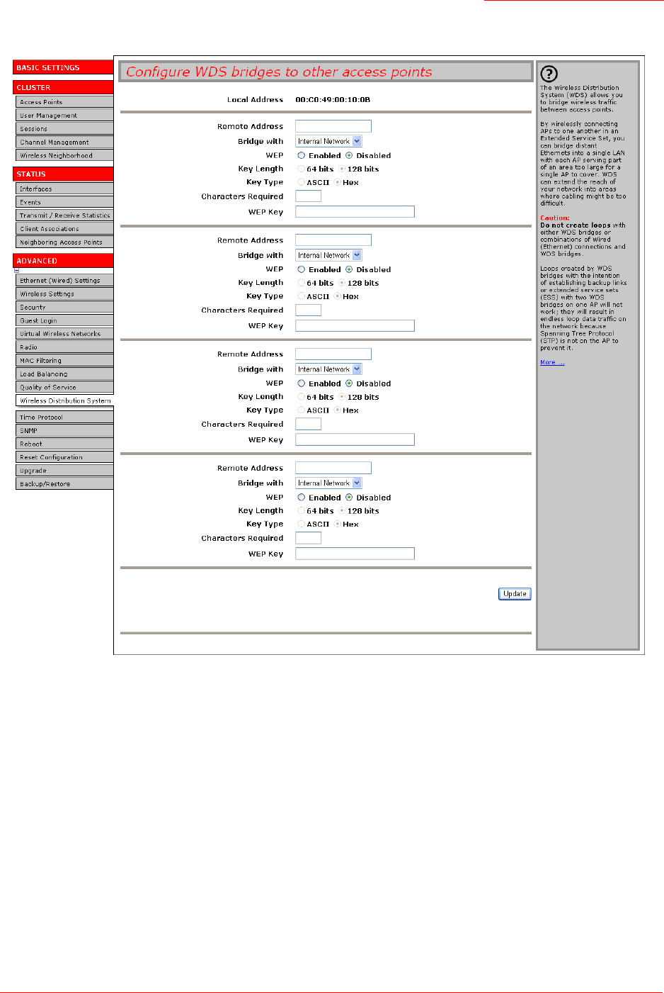
Professional Access Point
Administrator Guide
Wireless Distribution System - 146
Configuring WDS Settings
The following notes summarize critical guidelines regarding WDS configuration. Please read all the notes

Professional Access Point
Administrator Guide
Wireless Distribution System - 147
before proceeding with WDS configuration.
To configure WDS on this access point, describe each access point intended to receive hand-offs and
send information to this access point. Each destination access point needs the following description:
Notes
• The only security mode available on the WDS link is Static WEP, which is not particularly secure.
Therefore, USRobotics recommends using WDS to bridge the Guest network only. Do not use
WDS to bridge access points on the Internal network unless you are not concerned about the
security risk for data traffic on that network.
• When using WDS, be sure to configure WDS settings on both access points participating in the
WDS link.
• You can have only one WDS link between any pair of access points. That is, a remote MAC
address may appear only once on the WDS page for a particular access point.
• Both access points participating in a WDS link must be on the same radio channel and use the
same IEEE 802.11 mode. (See “Radio” on page 119 for information on configuring the Radio
mode and channel.)
•Do not create loops with either WDS bridges or combinations of Wired (Ethernet) connections
and WDS bridges. Spanning Tree Protocol (STP), which manages path redundancy and prevent
unwanted loops, is not available in the Professional Access Point. Keep these rules in mind when
working with WDS on the access point:
Any two access points can be connected by only a single path; either a WDS bridge (wireless) or
an Ethernet connection (wired), but not both.
Do not create backup links.
If you can trace more than one path between any pair of APs going through any combination of
Ethernet or WDS links, you have a loop.
You can only extend or bridge either the Internal or Guest network but not both.
Field Description
Local Address Indicates the Media Access Control (MAC) addresses for this access point.
This is a read-only field.
Remote Address Specify the MAC address of the destination access point; that is, the access
point to which data will be sent and from which data will be received.
Bridge with The Professional Access Point provides the capability of setting up guest and
internal networks on the same access point. (See “Guest Login” on page 111.)
The guest network typically provides internet access but isolates guest clients
from more sensitive areas of your internal network. It is common to have secu-
rity disabled on the guest network to provide open access. In contrast, the
internal network provides full access to protected information behind a firewall
and requires secure logins or certificates for access.
When using WDS to link one access point to another, you need to identify the
network within which you want the data exchange to occur. Specify the network
to which you want to bridge this access point:
• Internal Network
• Guest Network

Professional Access Point
Administrator Guide
Wireless Distribution System - 148
Example of Configuring a WDS Link
When using WDS, be sure to configure WDS settings on both access points on the WDS link.
For example, to create a WDS link between the pair of access points
MyAP1
and
MyAP2
do the following:
1. Open the Web User Interface for MyAP1 by entering the IP address for MyAP1 as a URL in the Web
browser address bar in the following form:
http://IPAddressOfAccessPoint
where
IPAddressOfAccessPoint
is the address of MyAP1.
2. Navigate to the WDS tab on MyAP1 Web User Interface.
WEP Specify whether you want Wired Equivalent Privacy (WEP) encryption enabled
for the WDS link.
• Enabled
• Disabled
Wired Equivalent Privacy (WEP) is a data encryption protocol for 802.11 wire-
less networks. Both access points on the WDS link must be configured with the
same security settings. For static WEP, a static 64-bit (40-bit secret key + 24-bit
initialization vector (IV)) or 128-bit (104-bit secret key + 24-bit IV) Shared Key
for data encryption.
Key Length If WEP is enabled, specify the length of the WEP key:
•64 bits
•128 bits
Key Type If WEP is enabled, specify the WEP key type:
•ASCII
•Hex
Characters Required Indicates the number of characters required in the WEP key.
The number of characters required updates automatically based on how you
set key length and key type.
WEP Key Enter a string of characters.
• If you selected ASCII as your key type, enter any combination of
0-9
,
a-z
,
and
A-Z
.
• If you selected HEX as your key type, enter hexadecimal digits (any combi-
nation of
0-9
and
a-f
or
A-F
).
These are the RC4 encryption keys shared with the stations using the access
point.
Field Description

Professional Access Point
Administrator Guide
Wireless Distribution System - 149
The MAC address for MyAP1 (the access point you are currently viewing) will appear as the Local
Address at the top of the page.
3. Configure a WDS interface for data exchange with MyAP2.
Start by entering the MAC address for MyAP2 as the Remote Address, and fill in the rest of the fields to
specify the network (guest or internal), security, and so on. Save the settings by clicking Update.
4. Navigate to the radio settings on the Web User Interface (Advanced menu’s Radio tab) to verify or set
the mode and the radio channel on which you want MyAP1 to broadcast.
Remember that the two access points participating in the link, MyAP1 and MyAP2, must be set to the
same mode and be transmitting on the same channel.
For this example, suppose that you are using IEEE 802.11b mode and broadcasting on Channel 6.
(Choose Mode and Channel from the drop-down lists on the Radio tab.)
5. Now repeat steps 1–4 for MyAP2:
• Open the Web User Interface for MyAP2 by using MyAP2’s IP address in a URL.
• Navigate to the WDS tab on MyAP2 Web User Interface. MyAP2’s MAC address will show as the
Local Address.
• Configure a WDS interface for data exchange with MyAP1, starting with the MAC address for
MyAP1.
• Navigate to the radio settings for MyAP2 to verify that it is using the same mode and broadcasting
on the same channel as MyAP1. In this example, Mode is 802.11b and the channel is 6.
• Be sure to save the settings by clicking Update.
Updating Settings
To apply your changes, click Update.

Professional Access Point
Administrator Guide
Wireless Distribution System - 150

Professional Access Point
Administrator Guide
Time Protocol - 151
Time Protocol
The Network Time Protocol (NTP) is an Internet standard protocol that synchronizes computer clock times
on your network. NTP servers transmit Coordinated Universal Time (UTC, also known as Greenwich Mean
Time) to their client systems. NTP sends periodic time requests to servers, using the returned time stamp
to adjust its clock.
The timestamp is used to indicate the date and time of each event in log messages.
See http://www.ntp.org for more general information on NTP.
The following sections describe how to configure the Professional Access Point to use a specified NTP
server:
•Navigating to Time Protocol Settings
•Enabling and Disabling a Network Time Protocol (NTP) Server
•Updating Settings
Navigating to Time Protocol Settings
To enable an NTP server, click the Advanced menu’s Time Protocol tab, and update the fields as described
below.
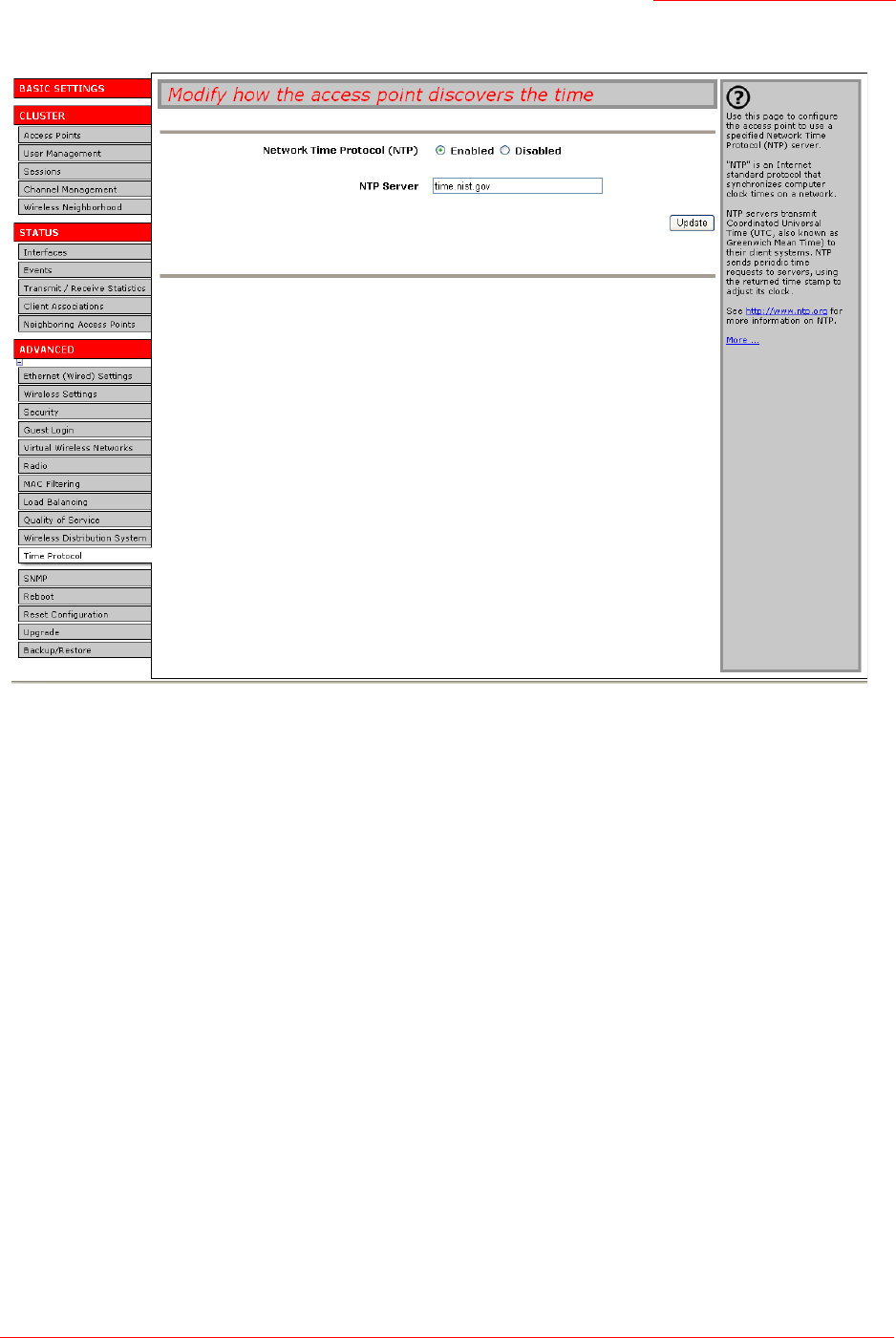
Professional Access Point
Administrator Guide
Time Protocol - 152
Enabling and Disabling a Network Time Protocol (NTP) Server
To configure your access point to use a network time protocol (NTP) server, first enable the use of NTP,
and then select the NTP server you want to use. (To shut down NTP service on the network, disable NTP
on the access point.

Professional Access Point
Administrator Guide
Time Protocol - 153
)
Updating Settings
To apply your changes, click Update.
Field Description
Network Time Protocol (NTP) NTP provides a way for the access point to obtain and maintain its time from a
server on the network. Using an NTP server gives your access point the ability
to provide the correct time of day in log messages and session information.
(See
http://www.ntp.org for more general information on NTP.)
Choose either to enable or to disable the use of a network time protocol (NTP)
server:
• Enabled
• Disabled
NTP Server If NTP is enabled, select the NTP server that you want to use.
You can specify the NTP server by host name or IP address. However, using
the host name is recommended because host names tend to be more constant
than IP addresses.

Professional Access Point
Administrator Guide
Time Protocol - 154