Cameo Communications USR5453 Professional Access Point User Manual Instant802 APSDK Getting Started Guide
Cameo Communications Inc Professional Access Point Instant802 APSDK Getting Started Guide
UserManual.wiki
>
Cameo Communications
>
USR5453 User Manual
>
Manual 1
Contents
1.
Manual 1
2.
Manual 2
Manual 1
Navigation menu
Upload a User Manual
Namespaces
Wiki Guide
HTML
PDF
Info
Views
User Manual
Discussion / Help
Navigation


![Professional Access Point Administrator GuideUser Management - 452. When you have filled in the fields, click Add Account to add the account.The new user is then displayed under User Accounts. The user account is enabled by default when you first create it.Editing a User AccountOnce you have created a user account, it is displayed under User Accounts at the top of the User Management Administration Web page. To modify an existing user account, first select [Edit] next to the user name.Then, make your changes in the Update Account section of the page and click Update Account.Enabling and Disabling User AccountsA user account must be enabled for the user to log on and use the access point.You can enable or disable any user account. With this feature, you can maintain a set of user accounts and authorize or prevent users from accessing the network without having to remove or re-create accounts. This ability is useful in situations where users have an occasional need to access the network. For example, contractors who do work for your company on an intermittent but regular basis might need network access for 3 months at a time, then be off for 3 months, and back on for another assignment. You can enable and disable these user accounts as needed, and control access as appropriate.Enabling a User AccountTo enable a user account, select the check box next to the user name and click Enable.Real Name For information purposes, provide the user’s full name.Real name is a maximum of 256 characters long.Password Specify a password for this user.The password is an alphanumeric string of up to 256 characters. Do not use special characters or spaces.NoteA limit of 100 user accounts per access point is imposed by the Web User Interface. Network usage may impose a more practical limit, depending upon the demand from each user. Field Description](https://usermanual.wiki/Cameo-Communications/USR5453.Manual-1/User-Guide-628650-Page-55.png)


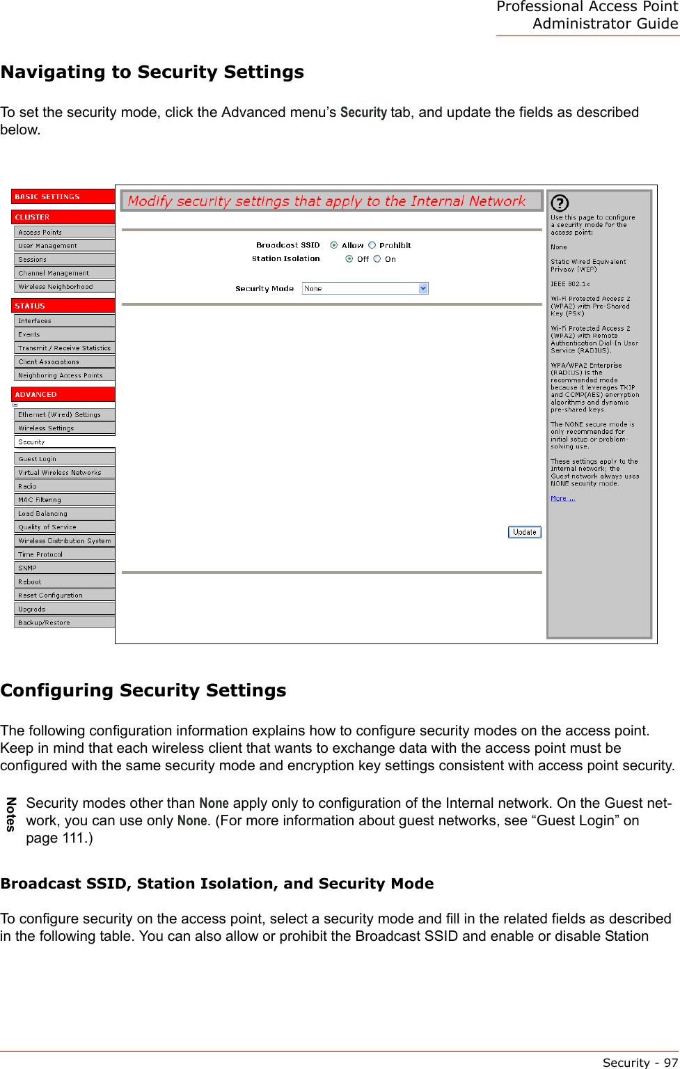

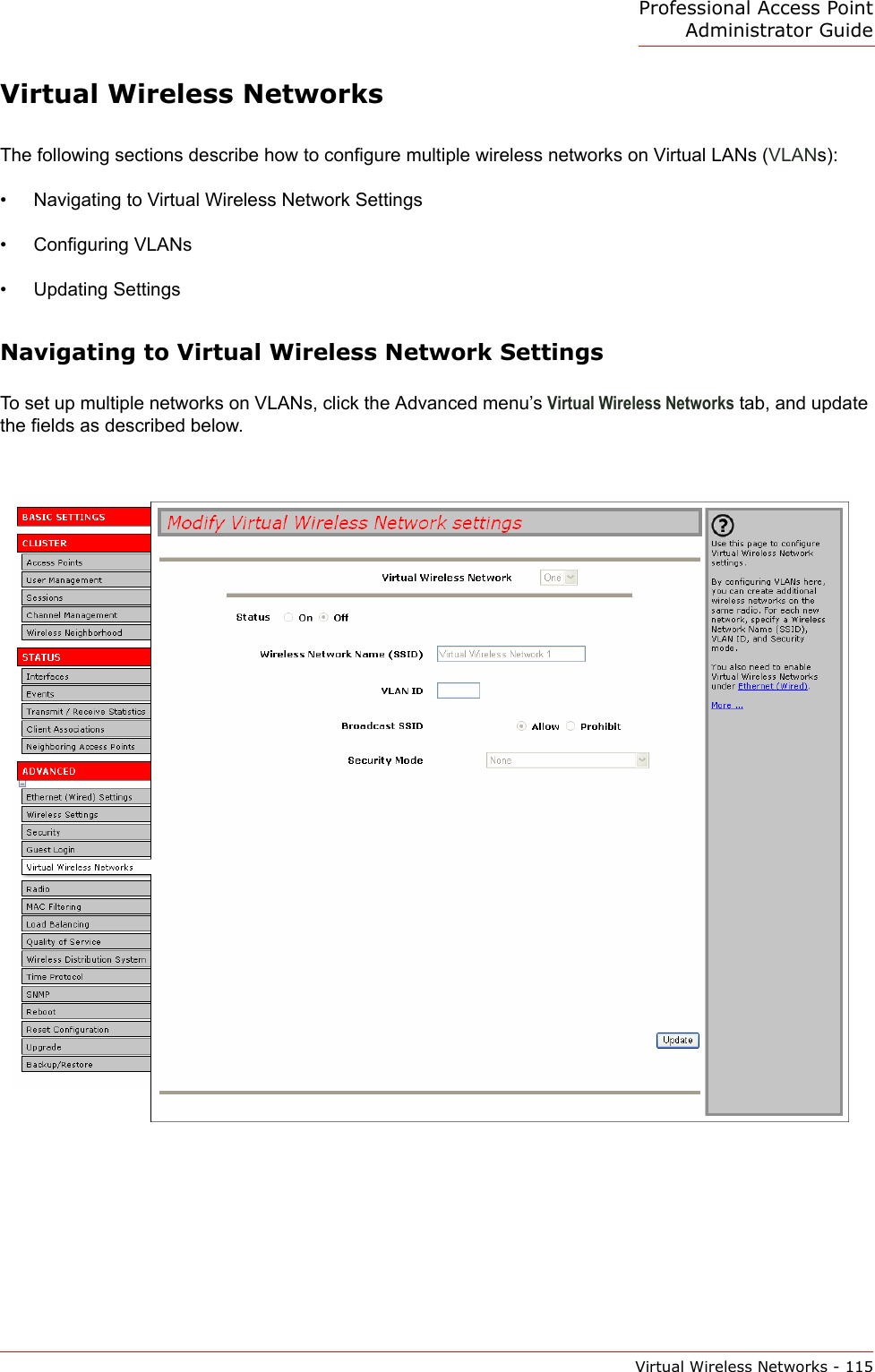
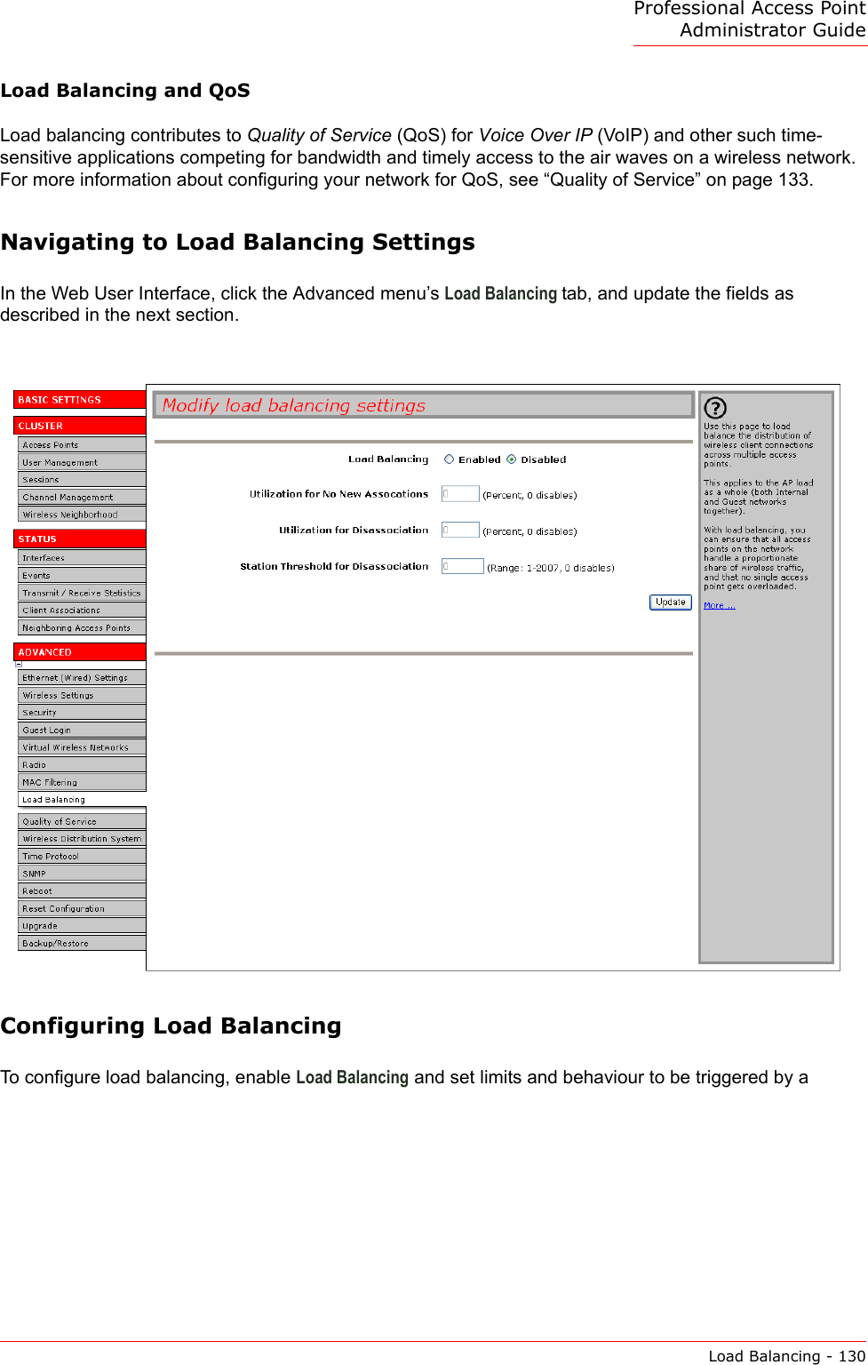
![Professional Access Point Administrator GuideVirtual Wireless Networks - 117Updating SettingsTo apply your changes, click Update. Broadcast SSID Select the Broadcast SSID setting by clicking the "Allow" or "Prohibit" radio but-ton. By default, the access point broadcasts (allows) the Service Set Identifier (SSID) in its beacon frames.You can suppress (prohibit) this broadcast to discourage stations from auto-matically discovering your access point. When the access point’s broadcast SSID is suppressed, the network name will not be displayed in the List of Avail-able Networks on a client device. Instead, the client must have the exact net-work name configured in the supplicant before it will be able to connect.Note: The Broadcast SSID you set here is specifically for this Virtual Network (One or Two). Other networks continue to use the security modes already configured:• Your original Internal network (configured on Advanced menu’s Ethernet [Wired] page) uses the Broadcast SSID set on Advanced menu’s Security page.• If a Guest network is configured, the Broadcast SSID is always allowed.Security Mode Select the Security Mode for this VLAN. Select one of the following:•None• Static WEP• IEEE 802.1x• WPA/WPA2 Personal (PSK)• WPA/WPA2 Enterprise (RADIUS)Note: The Security mode you set here is specifically for this Virtual Network (One or Two). Other networks continue to use the security modes already configured:• Your original Internal network uses the Security mode set on the Advanced menu’s Security page.• If a Guest network is configured, it always uses None.For a comparison of the available security modes, see “How Do I Know Which Security Mode to Use?” on page 91.Field Description](https://usermanual.wiki/Cameo-Communications/USR5453.Manual-1/User-Guide-628650-Page-127.png)