Cameo Communications USR5453 Professional Access Point User Manual Instant802 APSDK Getting Started Guide
Cameo Communications Inc Professional Access Point Instant802 APSDK Getting Started Guide
UserManual.wiki
>
Cameo Communications
>
USR5453 User Manual
>
Manual 2
Contents
1.
Manual 1
2.
Manual 2
Manual 2
Navigation menu
Upload a User Manual
Namespaces
Wiki Guide
HTML
PDF
Info
Views
User Manual
Discussion / Help
Navigation
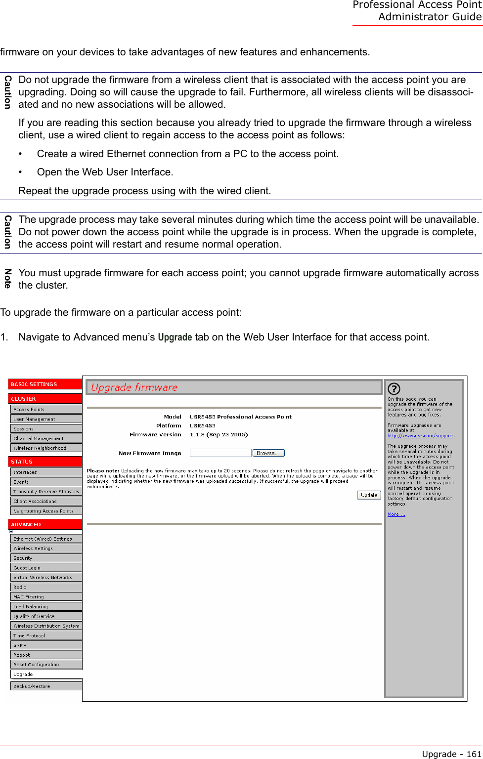
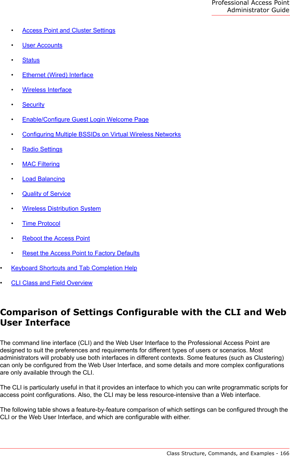
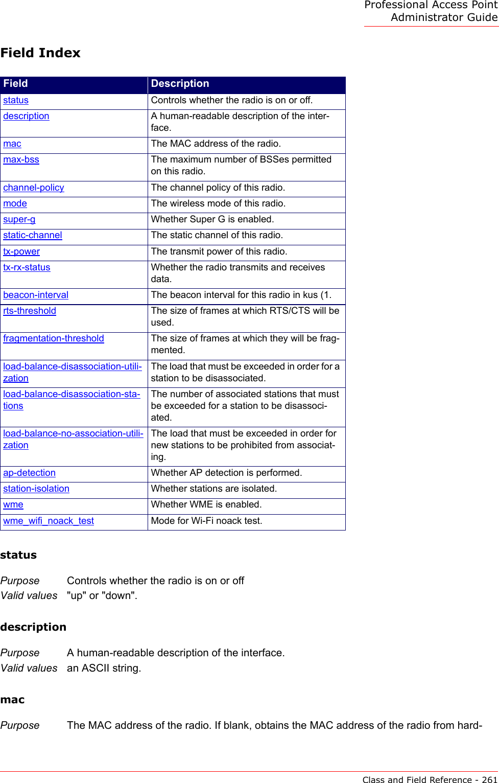
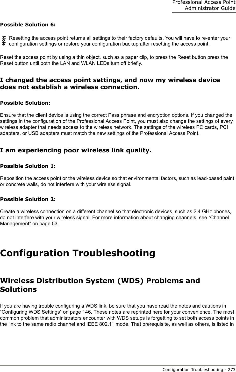
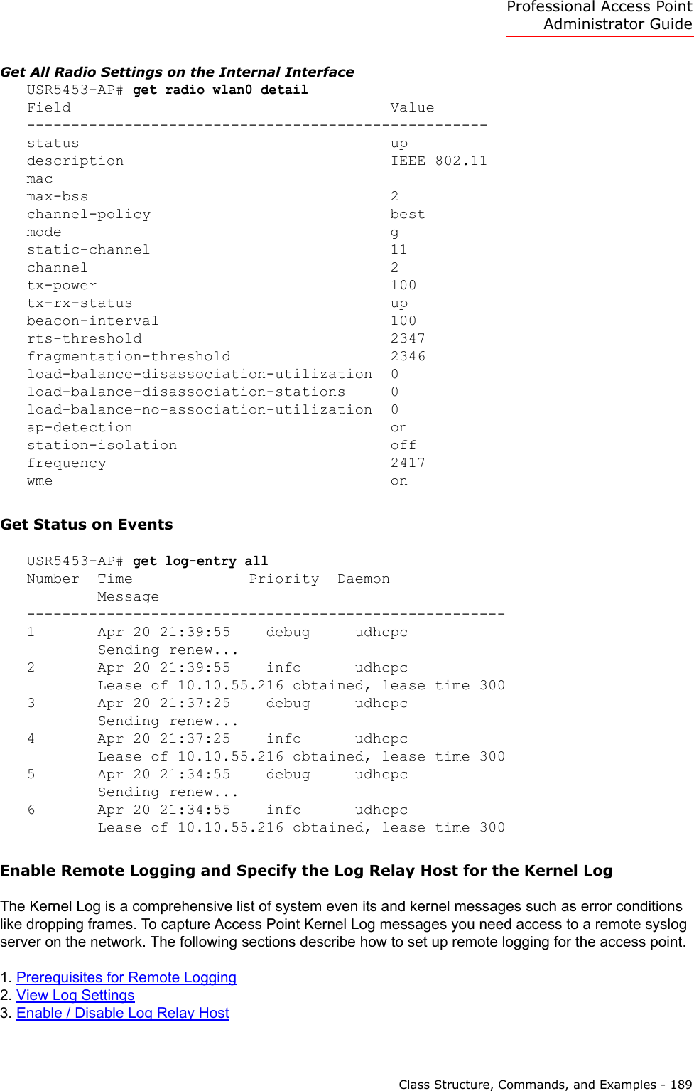
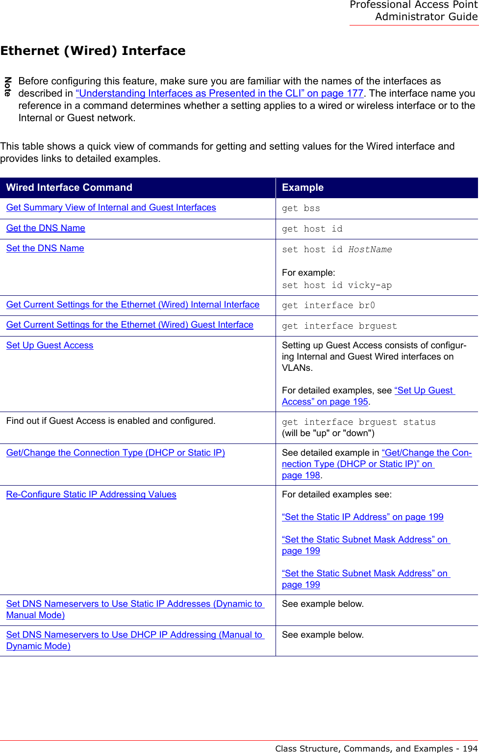
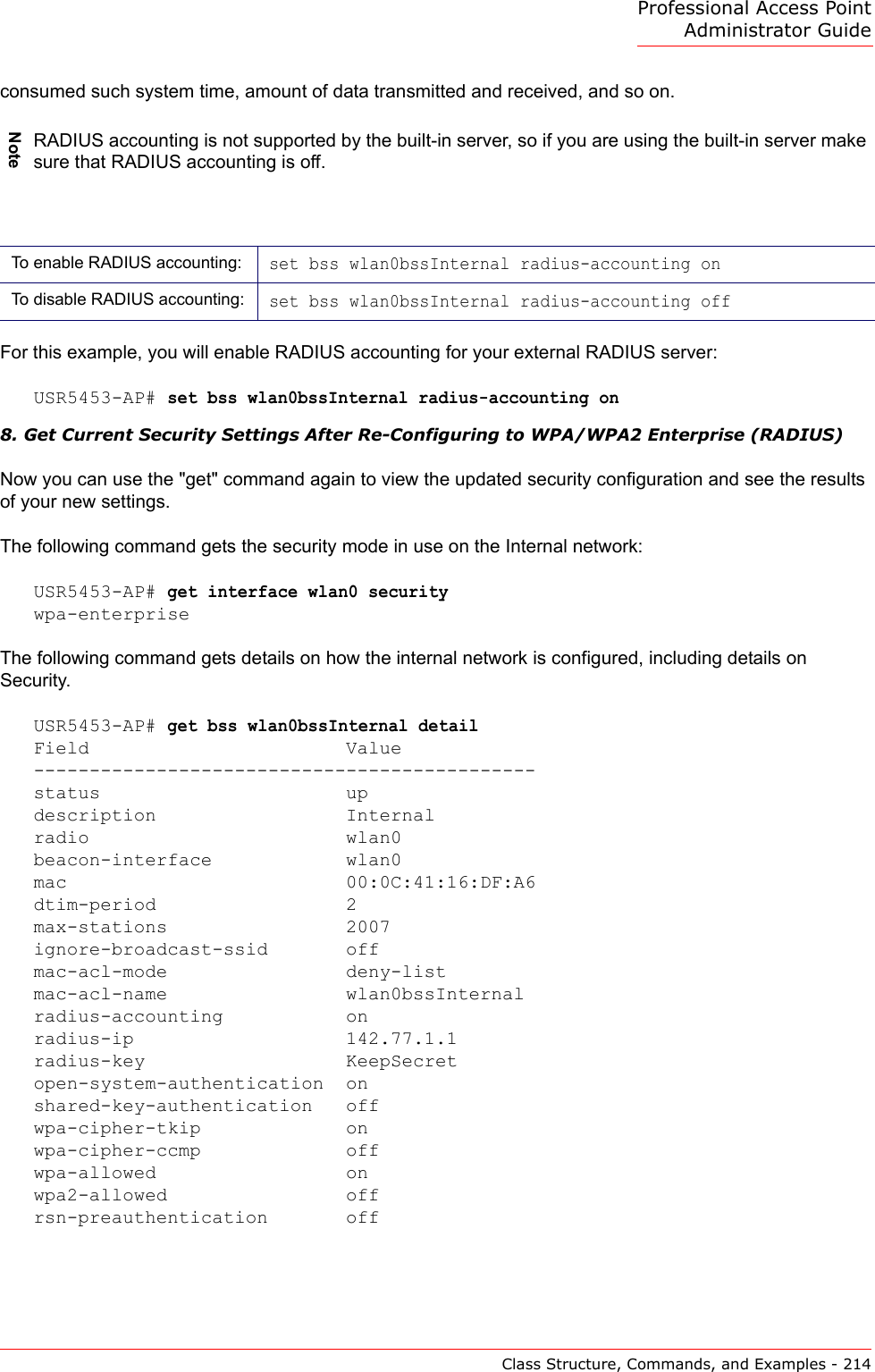
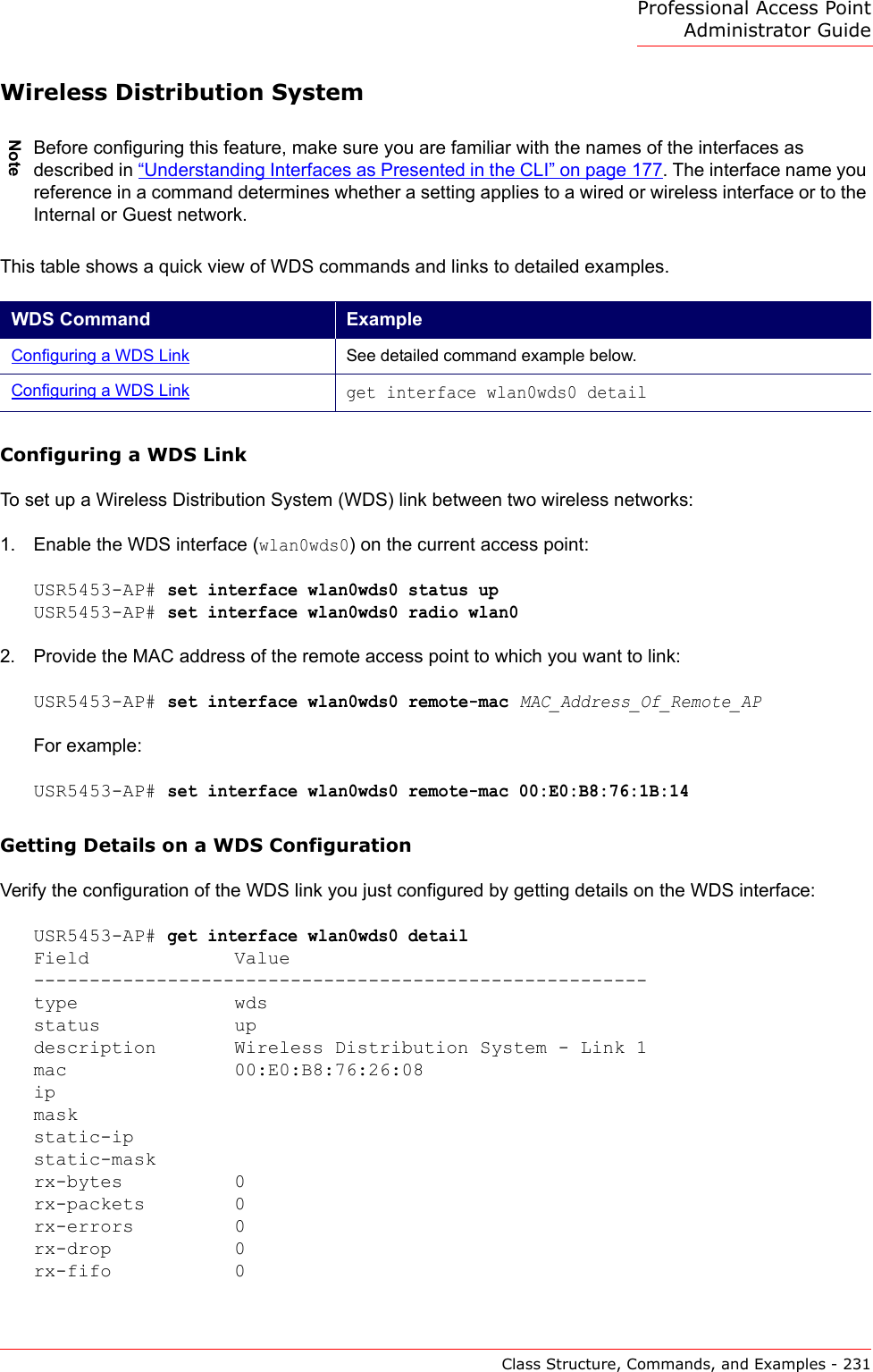
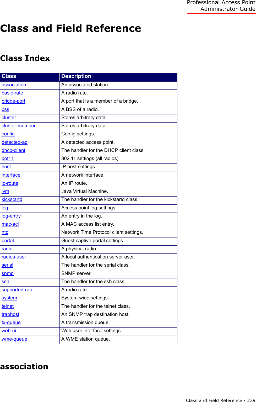
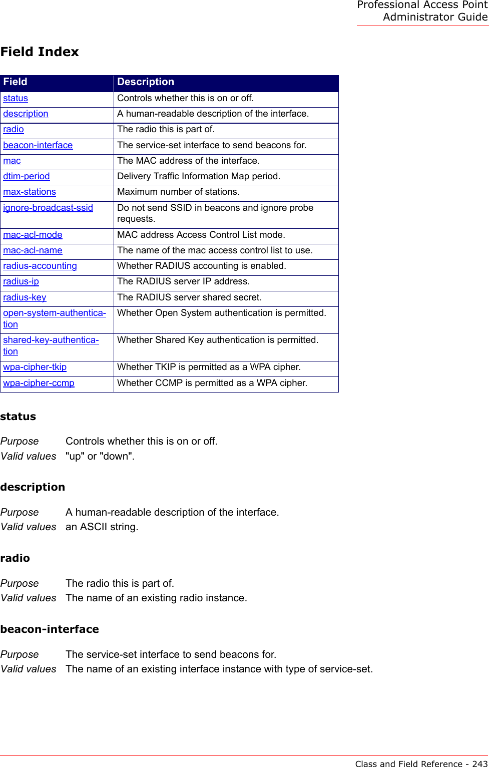
![Professional Access Point Administrator GuideClass Structure, Commands, and Examples - 172Command Descriptionget The "get" command allows you to get the field values of existing instances of a class. Classes can be "named" or "unnamed". The command syntax is:get unnamed-class [ field ... | detail ]get named-class [ instance | all [ field ... | name | detail ] ]The rest of the command line is optional. If provided, it is either a list of one or more fields, or the keyword detail.An example of using the "get" command on an unnamed class with a single instance is: get log (There is only one log on the access point. This command returns information on the log file.)An example of using the "get" command on an unnamed class with multiple instances is: get log-entry (There are multiple log entries but they are not named. This command returns all log entries.)An example of using the "get" command on a named class with multiple instances is: get bss wlan0bssInternal (There are multiple bss’s and they are named. This command returns information on the BSS named "wlan0bssInternal".)An example of using the "get" command on a named class to get all instances: get radius-user all name get radius-user allNote: "wlan0bssInternal" is the name of the basic service set (BSS) on the internal network (wlan0 interface). For information on interfaces, see “Understanding Interfaces as Presented in the CLI” on page 177.](https://usermanual.wiki/Cameo-Communications/USR5453.Manual-2/User-Guide-628651-Page-18.png)
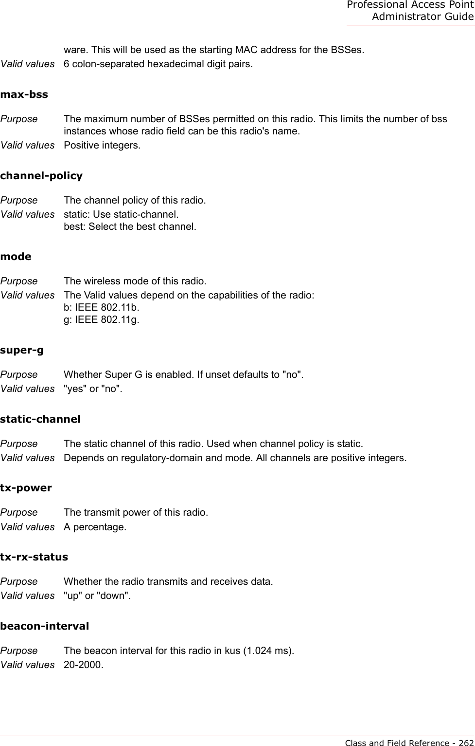
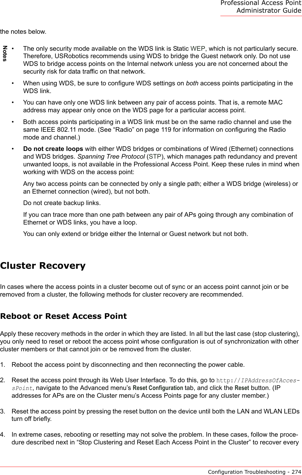
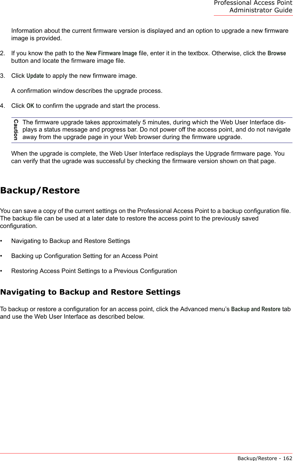
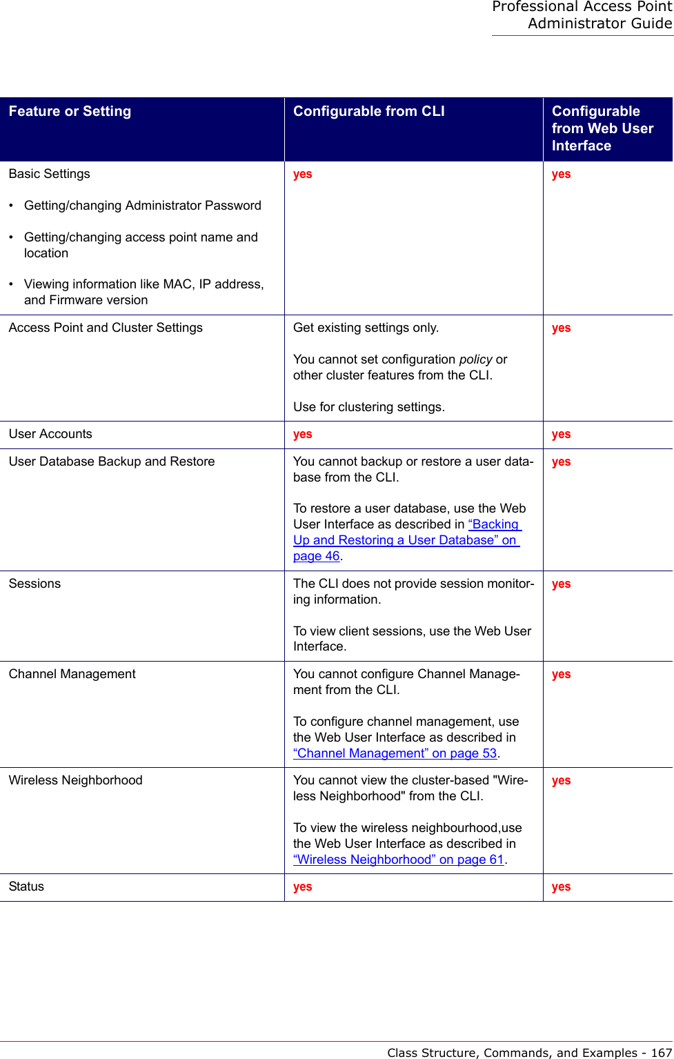
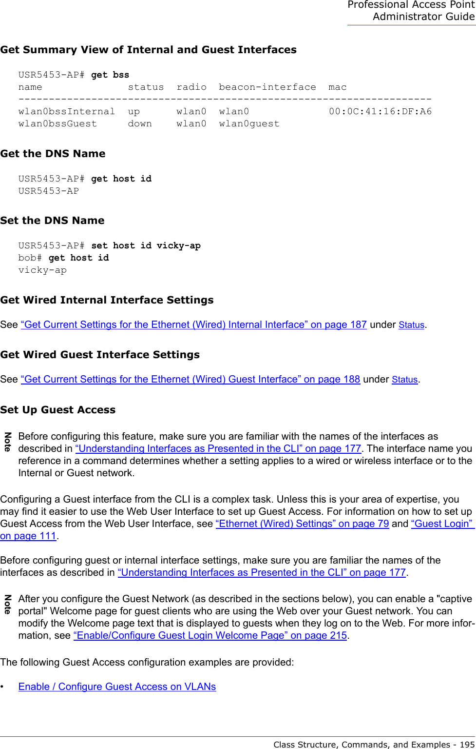
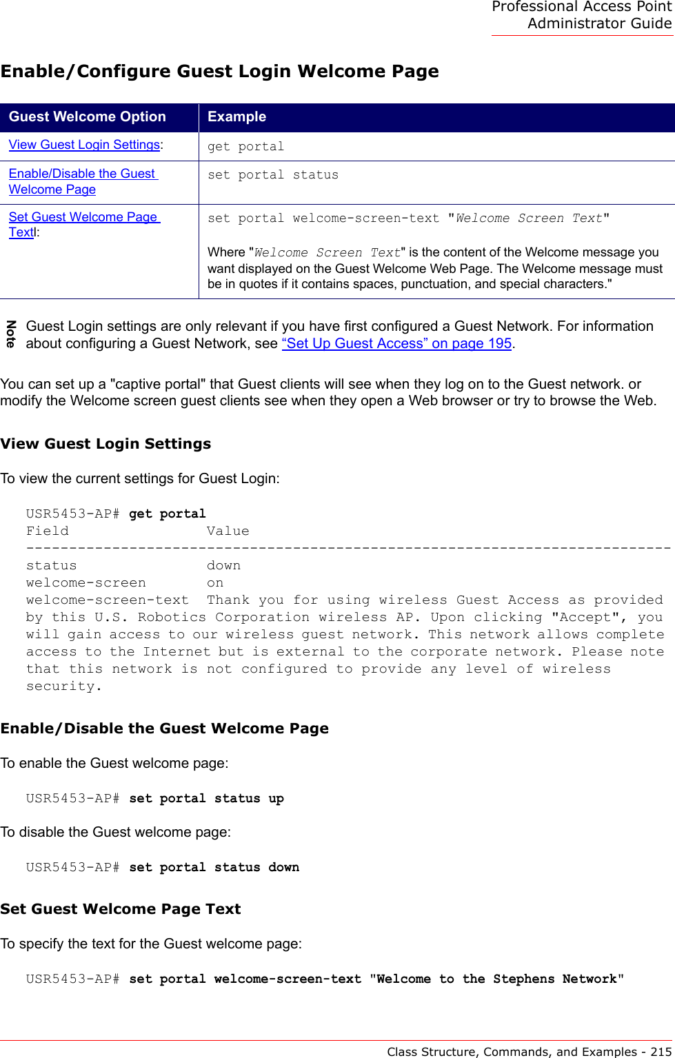
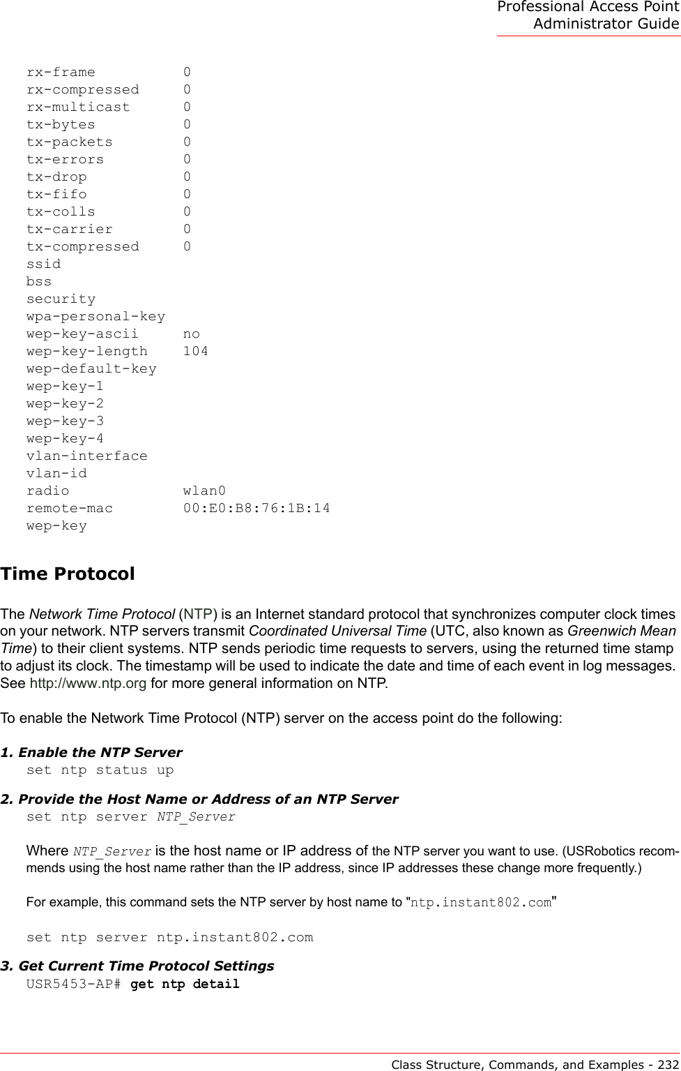
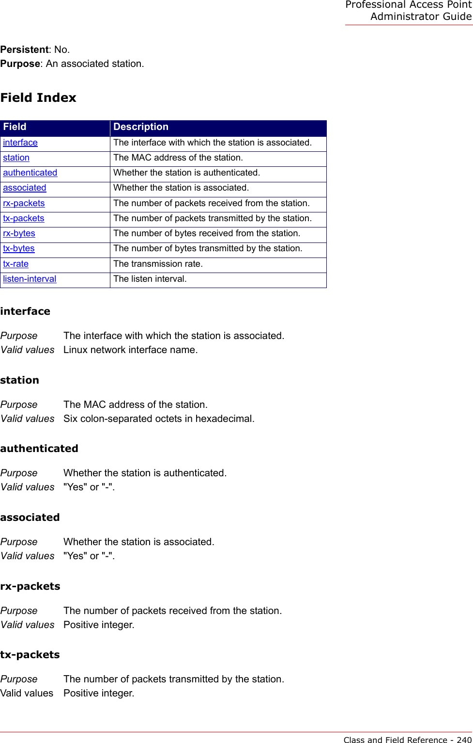
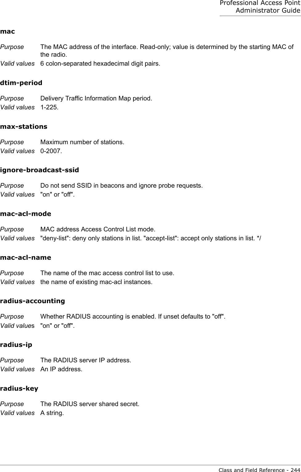
![Professional Access Point Administrator GuideClass Structure, Commands, and Examples - 173set The "set" command allows you to set the field values of existing instances of a class.set unnamed-class [ with qualifier-field qualifier-value ... to ] field value . . .The first argument is an unnamed class in the configuration.After this is an optional qualifier that restricts the set to only some instances. For single-ton classes (with only one instance) no qualifier is needed. If there is a qualifier, it starts with the keyword with, then has a sequence of one or more qualifier-field qualifier-value pairs, and ends with the keyword to. If these are included, then only instances whose present value of qualifier-field is qualifier-value will be set. The qualifier-value arguments cannot contain spaces. Therefore, you cannot select instances whose desired qualifier-value has a space in it.The rest of the command line contains field-value pairs.set named-class instance | all [ with qualifier-field qualifier-value ... to ] field value . . .The first argument is either a named class in the configuration.The next argument is the name of the instance to set, or the keyword all, which indi-cates that all instances should be set. Classes with multiple instances can be set con-secutively in the same command line as shown in Example 4 below. The qualifier-value arguments cannot contain spaces.Here are some examples. (Bold text indicates class names, field names, or keywords; text that is not bold indicates values to which the fields are being set.)1. set interface wlan0 ssid "Vicky's AP" 2. set radio all beacon-interval 200 3. set tx-queue wlan0 with queue data0 to aifs 3 4. set tx-queue wlan0 with queue data0 to aifs 7 cwmin 15 cwmax 1024 burst 0 5. set bridge-port br0 with interface eth0 to path-cost 200Note: For information on interfaces used in this example (such as wlan0, br0, or eth0) see “Understanding Interfaces as Presented in the CLI” on page 177.add The "add" command allows you to add a new instance of a class.add named-class instance [ field value ... ]add anonymous-class [ field value ... ]For example: add radius-user wally Command Description](https://usermanual.wiki/Cameo-Communications/USR5453.Manual-2/User-Guide-628651-Page-19.png)
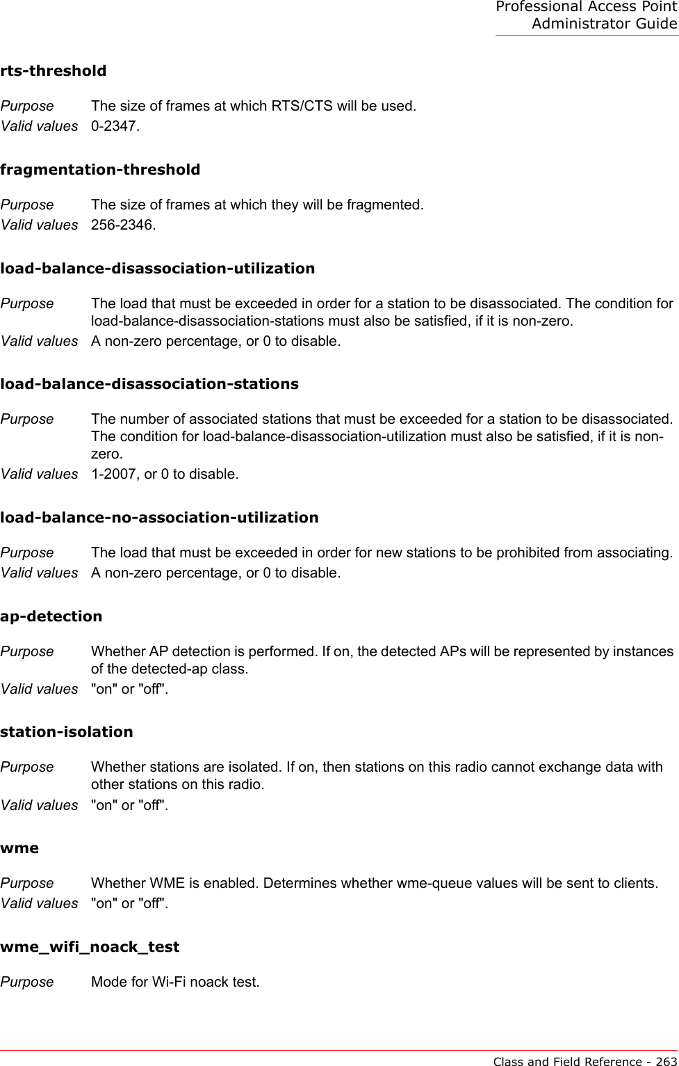
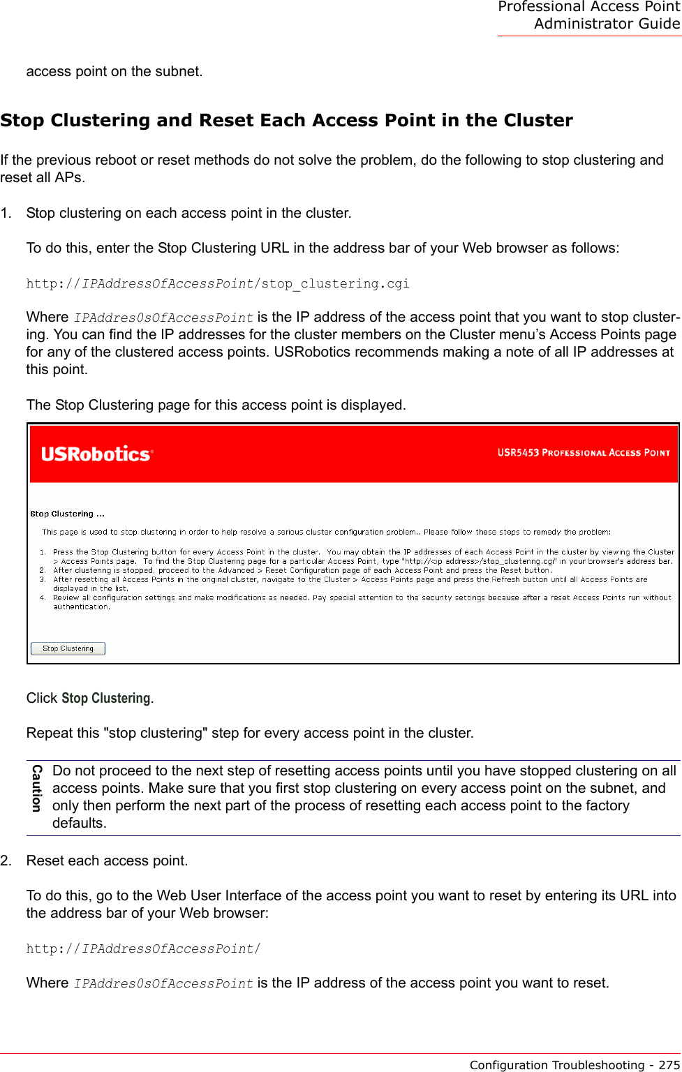
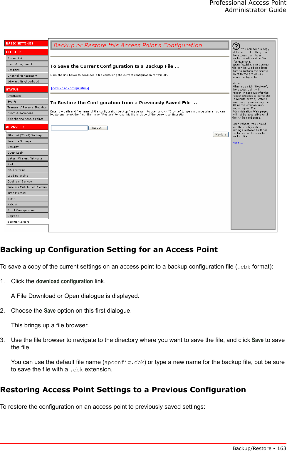
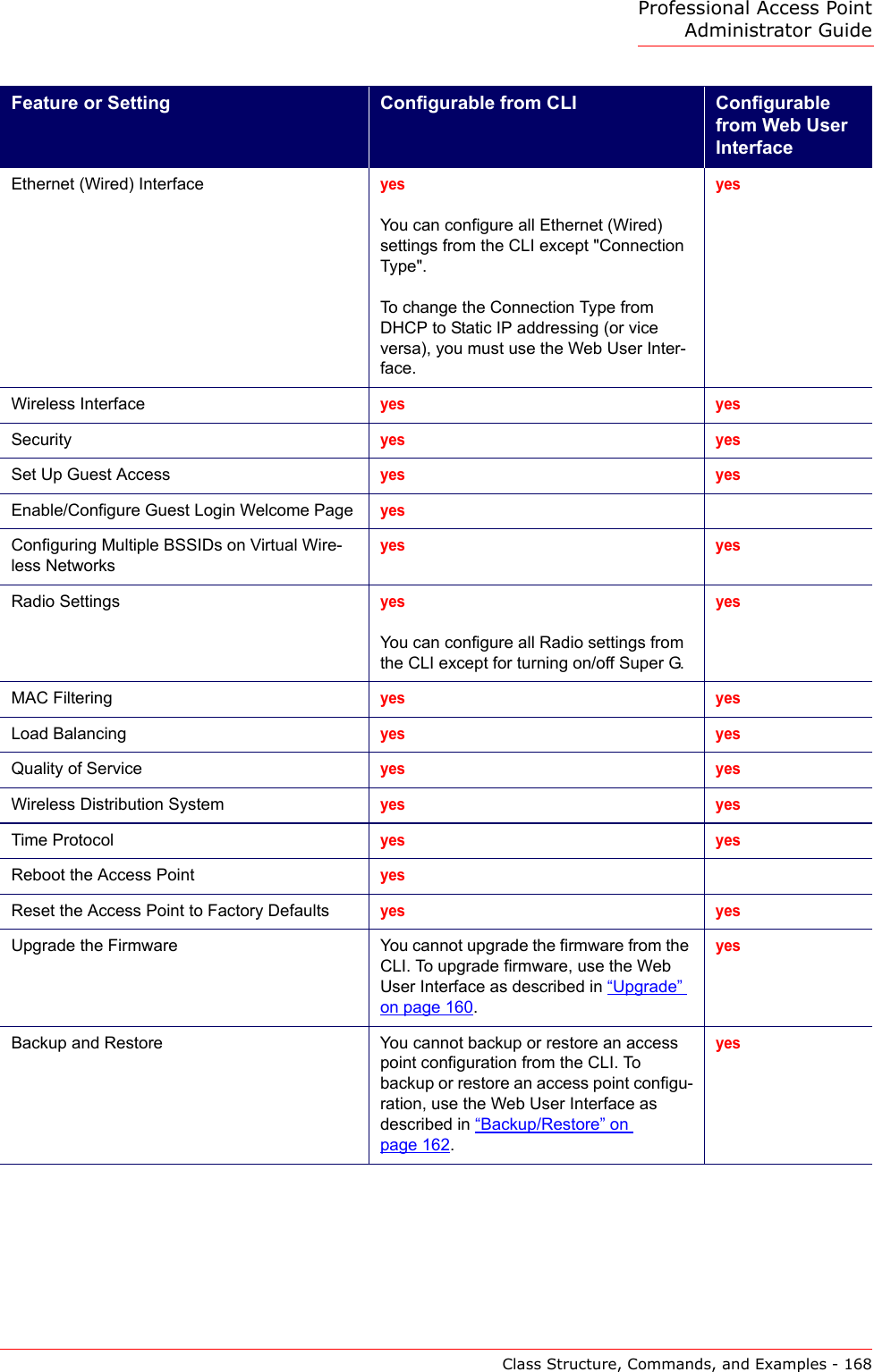
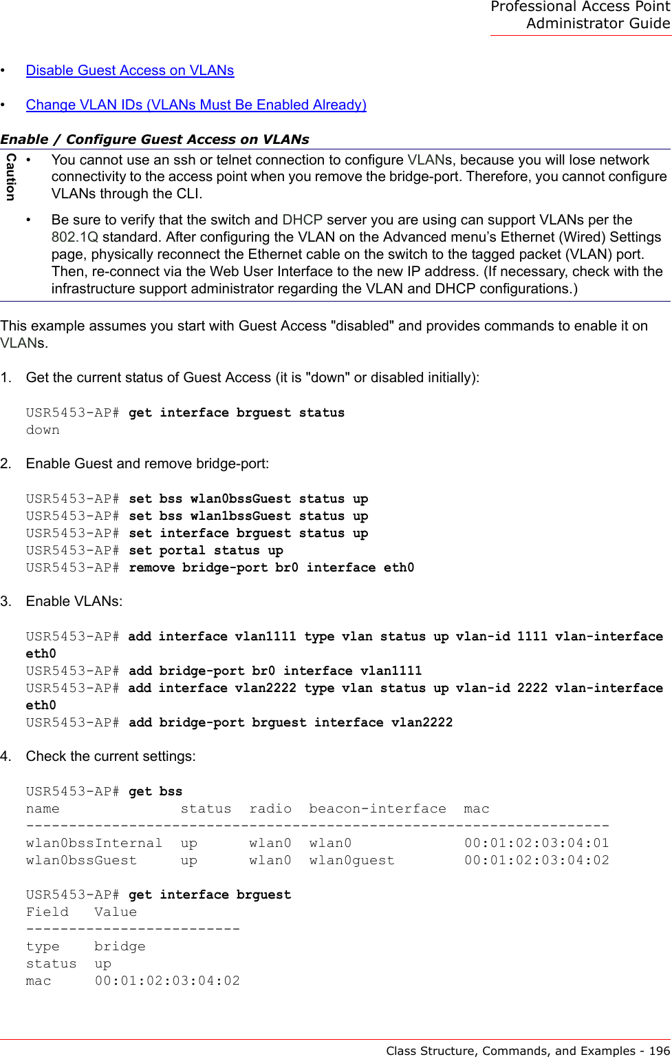
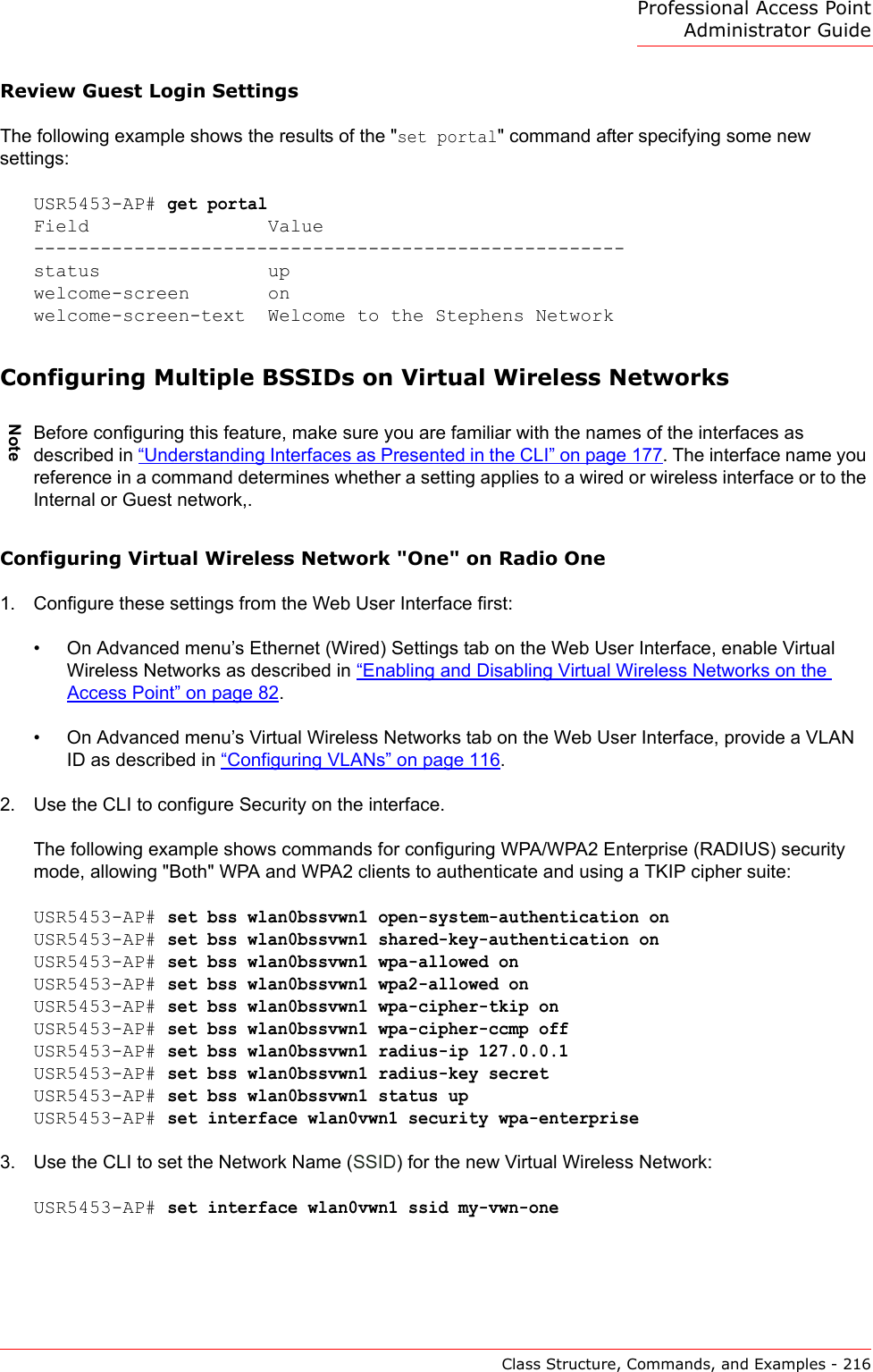
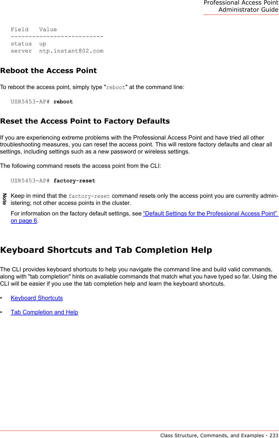
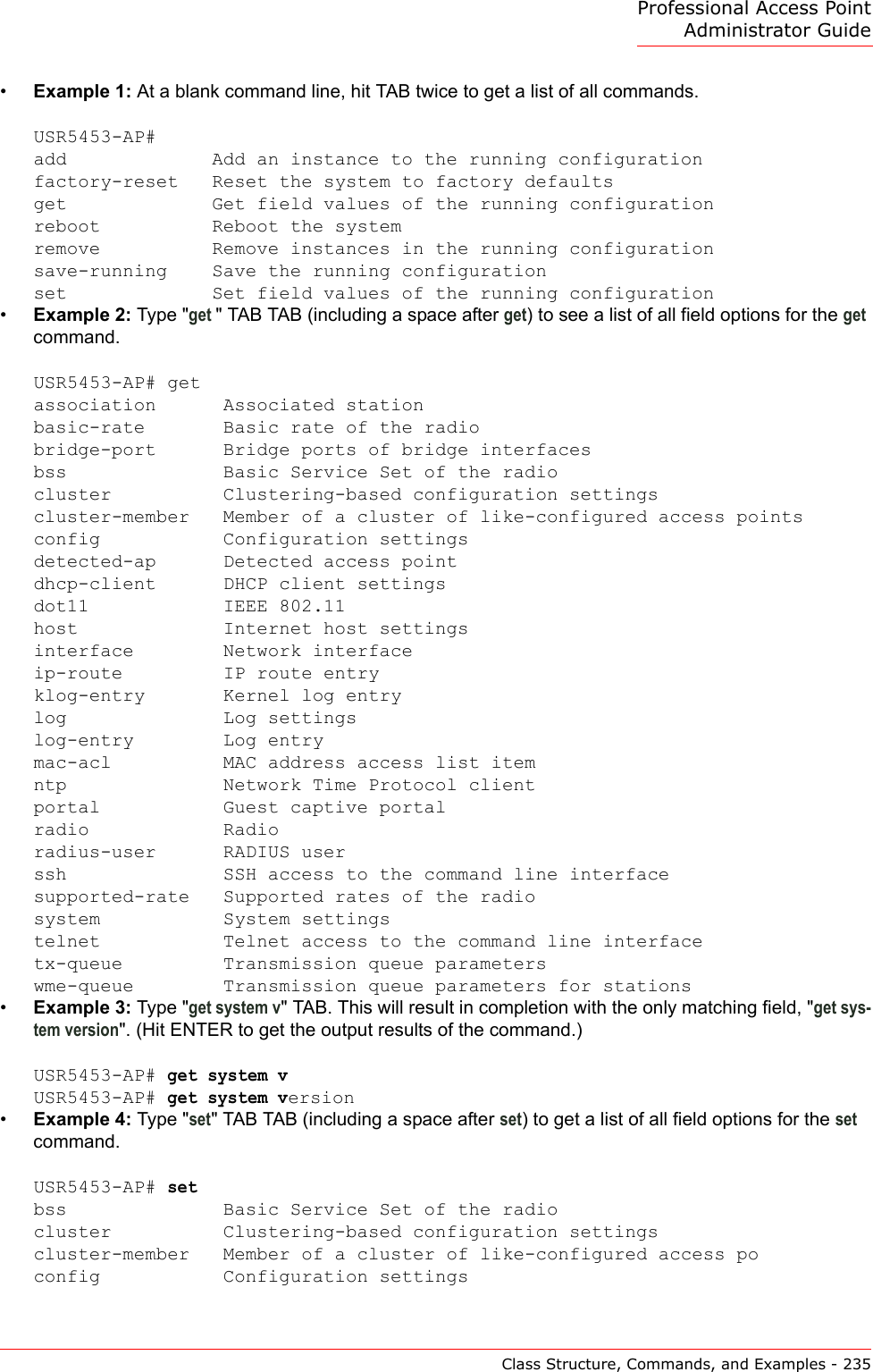
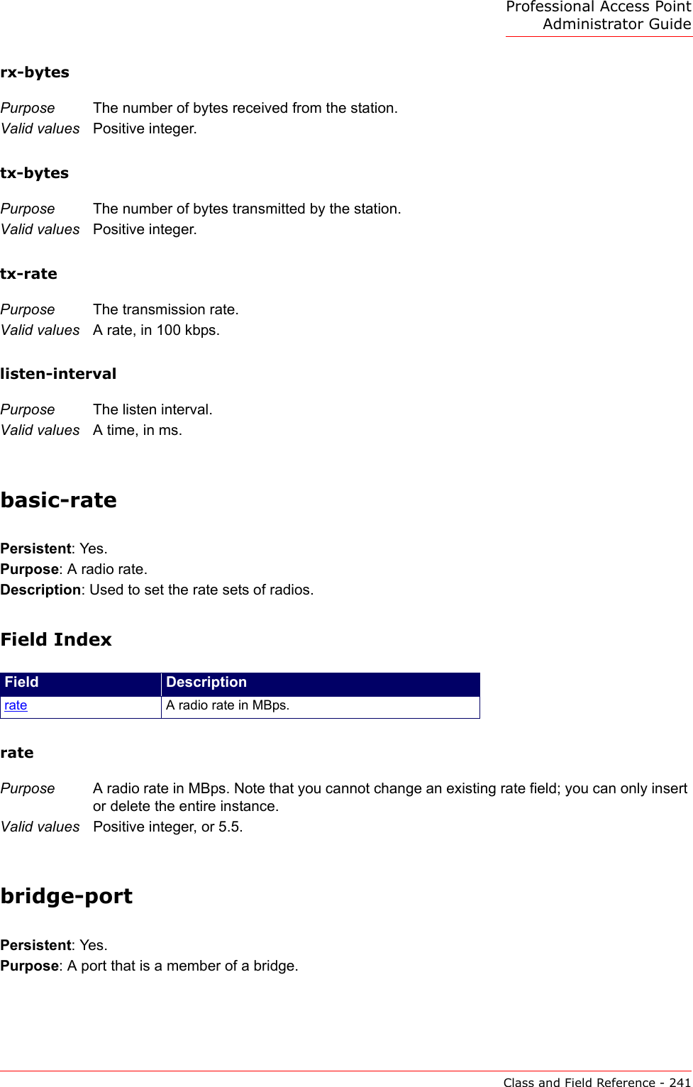
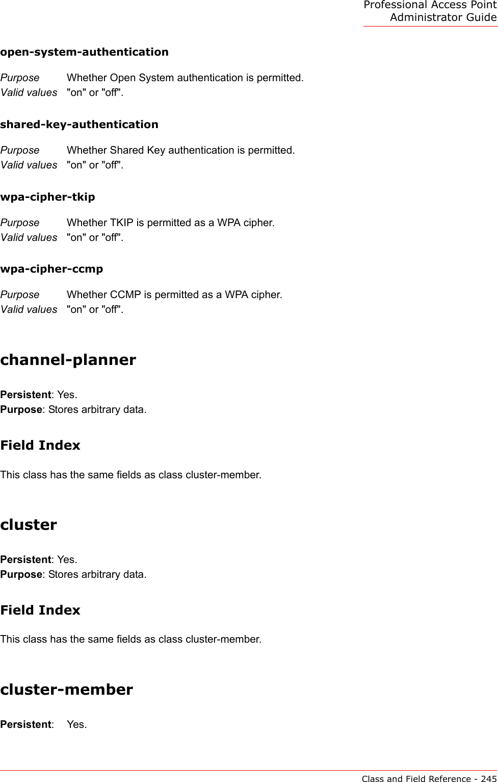
![Professional Access Point Administrator GuideClass Structure, Commands, and Examples - 174The CLI also includes the following commands for maintenance tasks:Getting Help on Commands at the CLIHelp on commands can be requested at the command line interface (CLI) by using the TAB key. This is a quick way to see all valid completions for a class.Hitting TAB once will attempt to complete the current command.If multiple completions exist, a beep will sound and no results will be displayed. Enter TAB again to display all available completions.•Example 1: At a blank command line, hit TAB twice to get a list of all commands.USR5453-AP#add Add an instance to the running configurationfactory-reset Reset the system to factory defaultsget Get field values of the running configurationreboot Reboot the systemremove Remove instances in the running configurationsave-running Save the running configurationset Set field values of the running configuration•Example 2: Type "get " TAB TAB (including a space after get) to see a list of all field options for the get command.USR5453-AP# getassociation Associated stationbasic-rate Basic rate of the radiobridge-port Bridge ports of bridge interfacesbss Basic Service Set of the radiocluster Clustering-based configuration settingsremove The "remove" command allows you to remove an existing instance of a class.remove unnamed-class [ field value . . . ]remove named-class instance | all [ field value . . .]For example: remove radius-user wallysave-running The save-running command saves the running configuration as the startup configuration.For more information, see ““Saving Configuration Changes” on page 178.reboot The reboot command restarts the access point (a soft reboot).For more information, see ““Reboot the Access Point” on page 233.factory-reset The factory-reset command resets the access point to factory defaults and reboots.For more information, see ““Reset the Access Point to Factory Defaults” on page 233.Command Description](https://usermanual.wiki/Cameo-Communications/USR5453.Manual-2/User-Guide-628651-Page-20.png)

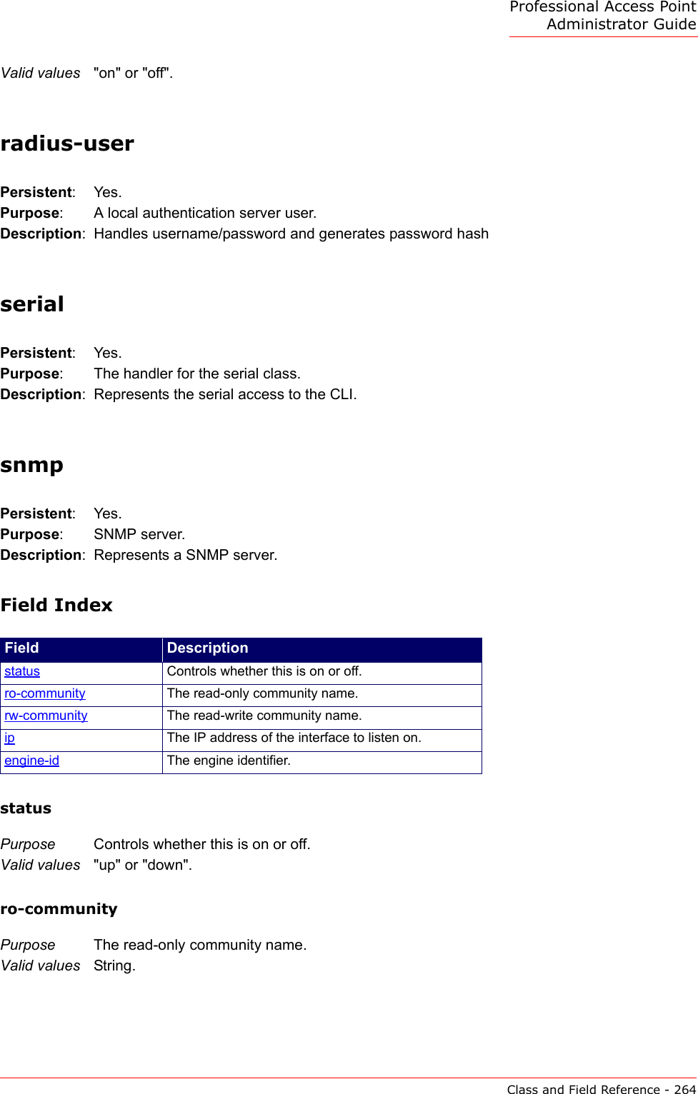
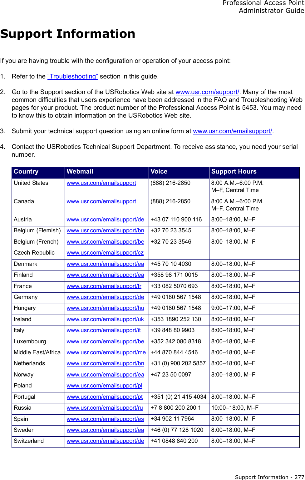
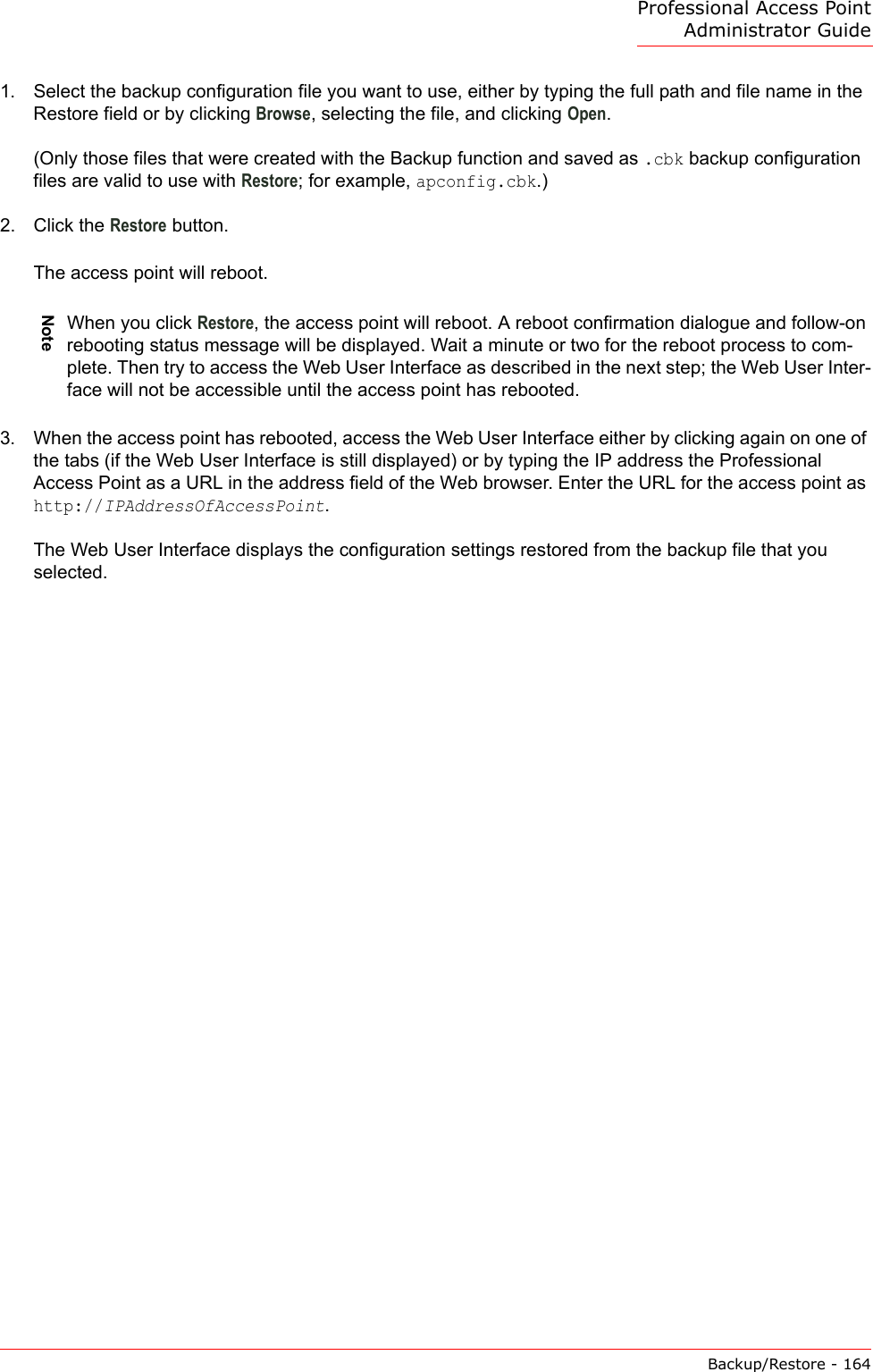
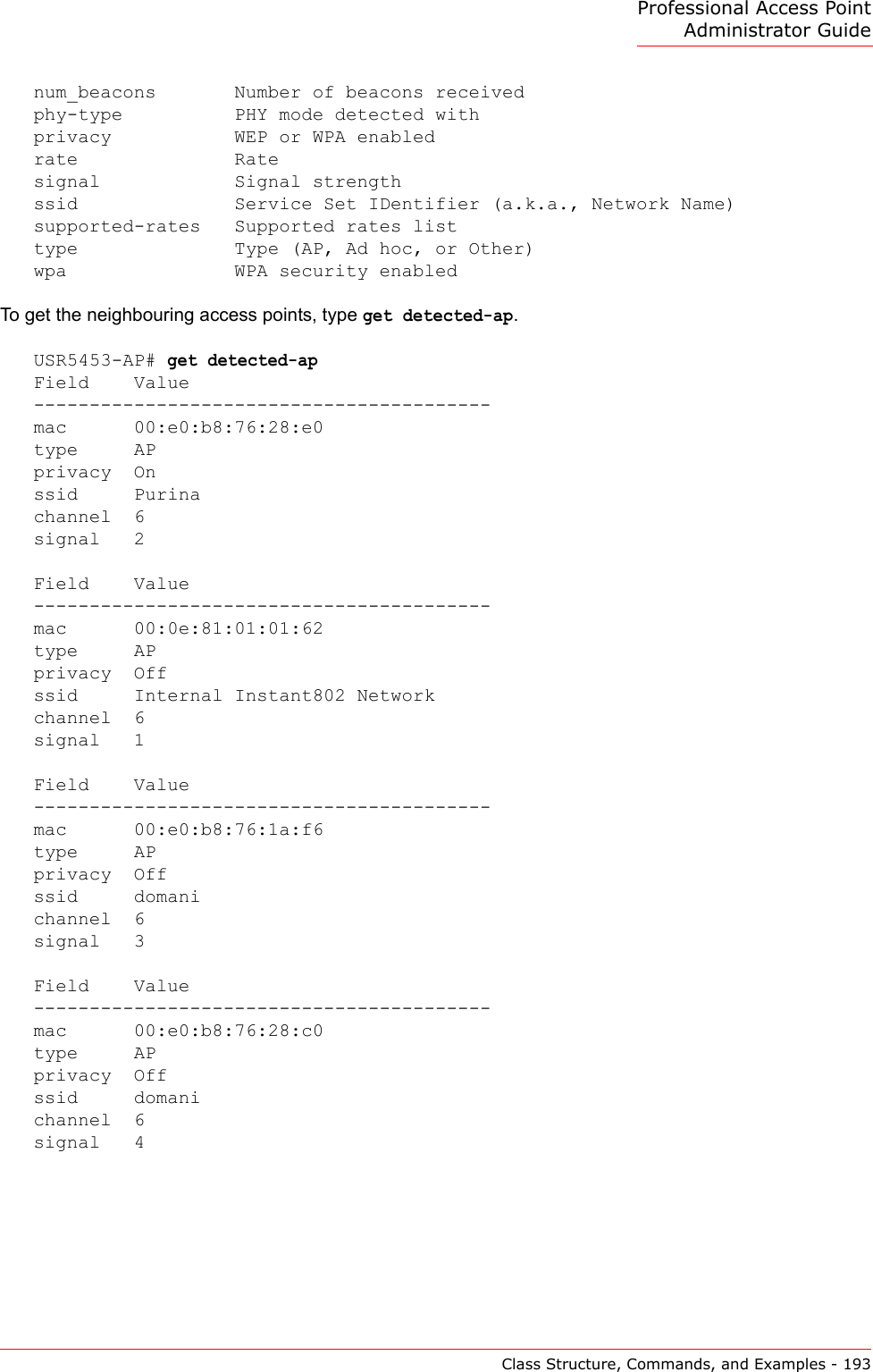
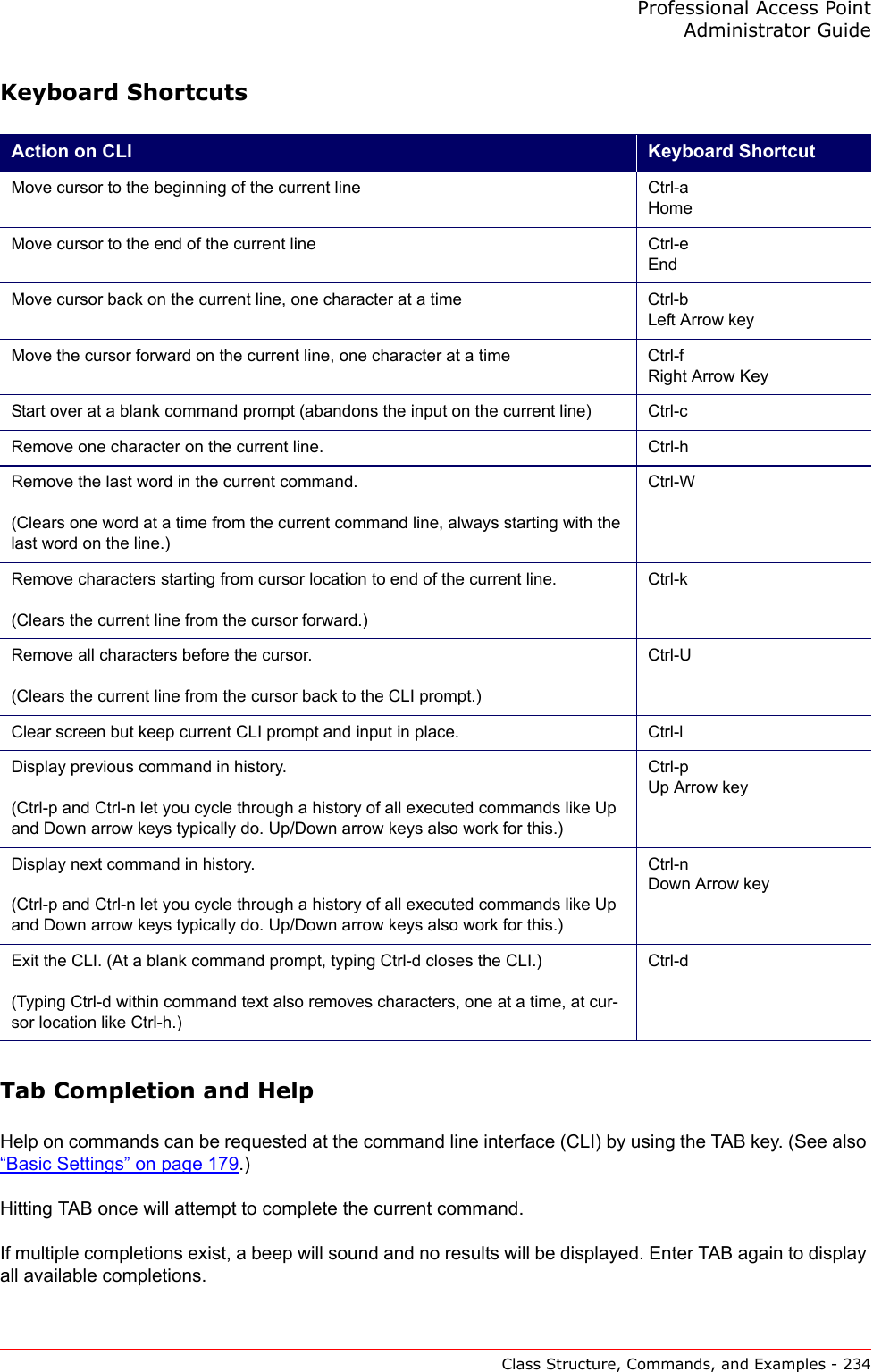
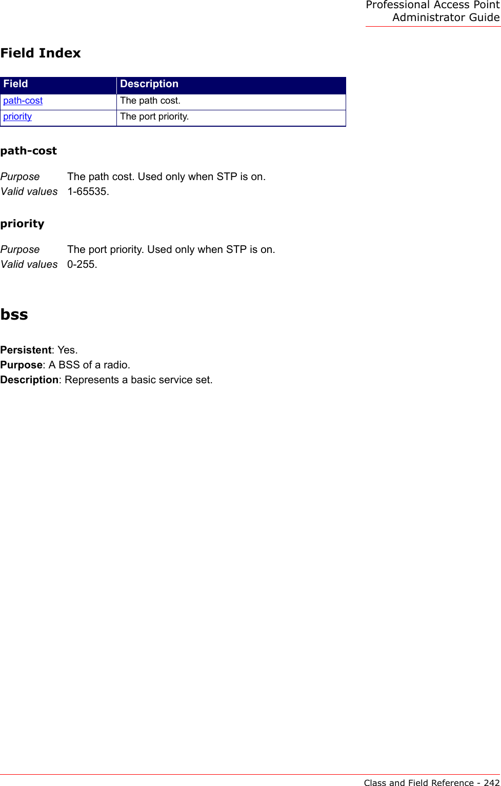
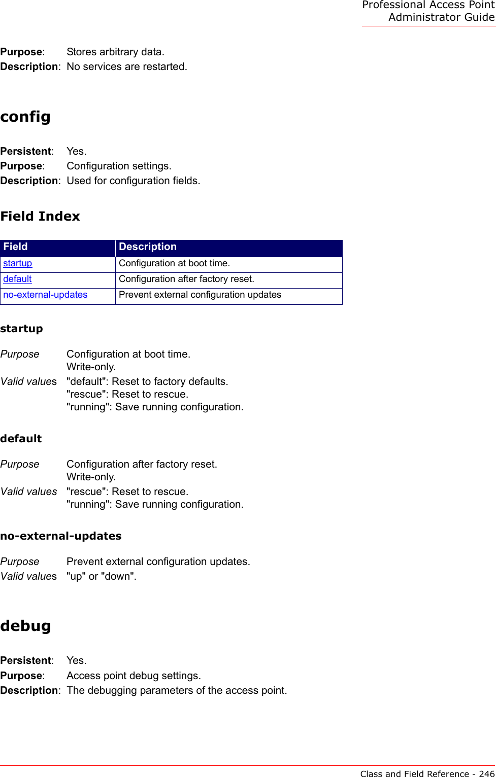
![Professional Access Point Administrator GuideClass Structure, Commands, and Examples - 192Name Ip Mac Ssid Tx-packets Tx-bytes Tx-errors Rx-packets Rx-bytes Rx-errors---------------------------------------------------------------------------lo 127.0.0.1 00:00:00:00:00:00 1319 151772 0 1319 151772 0eth0 00:A0:C9:8C:C4:7E 4699 3025566 0 11323 1259824 0eth1 0.0.0.0 00:50:04:6F:6F:90 152 49400 0 6632 664298 0br0 10.10.55.216 00:A0:C9:8C:C4:7E 4699 3025566 0 10467 885264 0brguest 10.10.56.248 00:50:04:6F:6F:90 152 48032 0 5909 293550 0wlan0 0.0.0.0 02:0C:41:00:02:00 AAP1000 (Trusted) 6483 710681 0 0 0 0wlan0guest 0.0.0.0 02:0C:41:00:02:01 AAP1000 (Guest) 5963 471228 0 0 0 0wlan0wds0wlan0wds1wlan0wds2wlan0wds3Get Client AssociationsUSR5453-AP# get associationInterf Station Authen Associ Rx-pac Tx-pac Rx-byt Tx-byt Tx-ratwlan0 00:0c:41:8f:a7:72 Yes Yes 126 29 9222 3055 540wlan0 00:09:5b:2f:a5:2f Yes Yes 382 97 16620 10065 110USR5453-AP# get association detailInter Station Authe Assoc Rx-pa Tx-pa Rx-byt Tx-byt Tx-ra Listewlan0 00:0c:41:8f:a7:72 Yes Yes 126 29 9222 3055 540 1wlan0 00:09:5b:2f:a5:2f Yes Yes 382 97 16620 10065 110 1Get neighbouring Access PointsThe Neighboring access point view shows wireless networks within range of the access point. These commands provide a detailed view of neighboring access points including identifying information (SSIDs and MAC addresses) for each, and statistical information such as the channel each access point is broadcasting on, signal strength, and so forth.To see the kinds of information about access point neighbours you can search on, type get detected-ap TAB TAB.USR5453-AP# get detected-ap[Enter] * Get common fields *band Frequency bandbeacon-interval Beacon interval in kus (1.024 ms)capability IEEE 802.11 capability valuechannel Channeldetail * Get all fields *erp ERPlast-beacon Time of last beaconmac MAC address](https://usermanual.wiki/Cameo-Communications/USR5453.Manual-2/User-Guide-628651-Page-38.png)
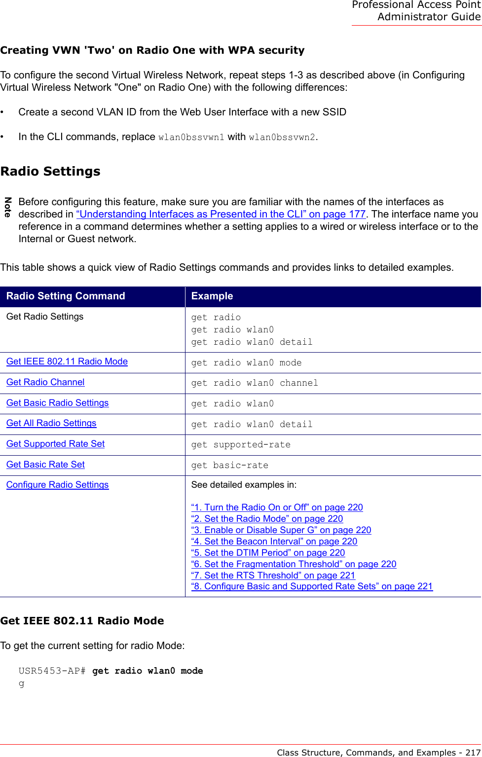
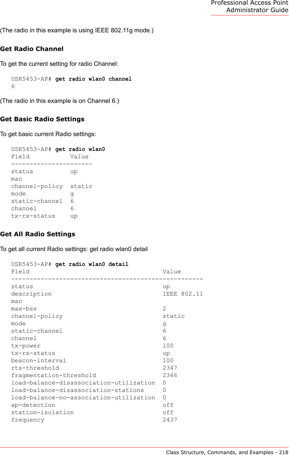
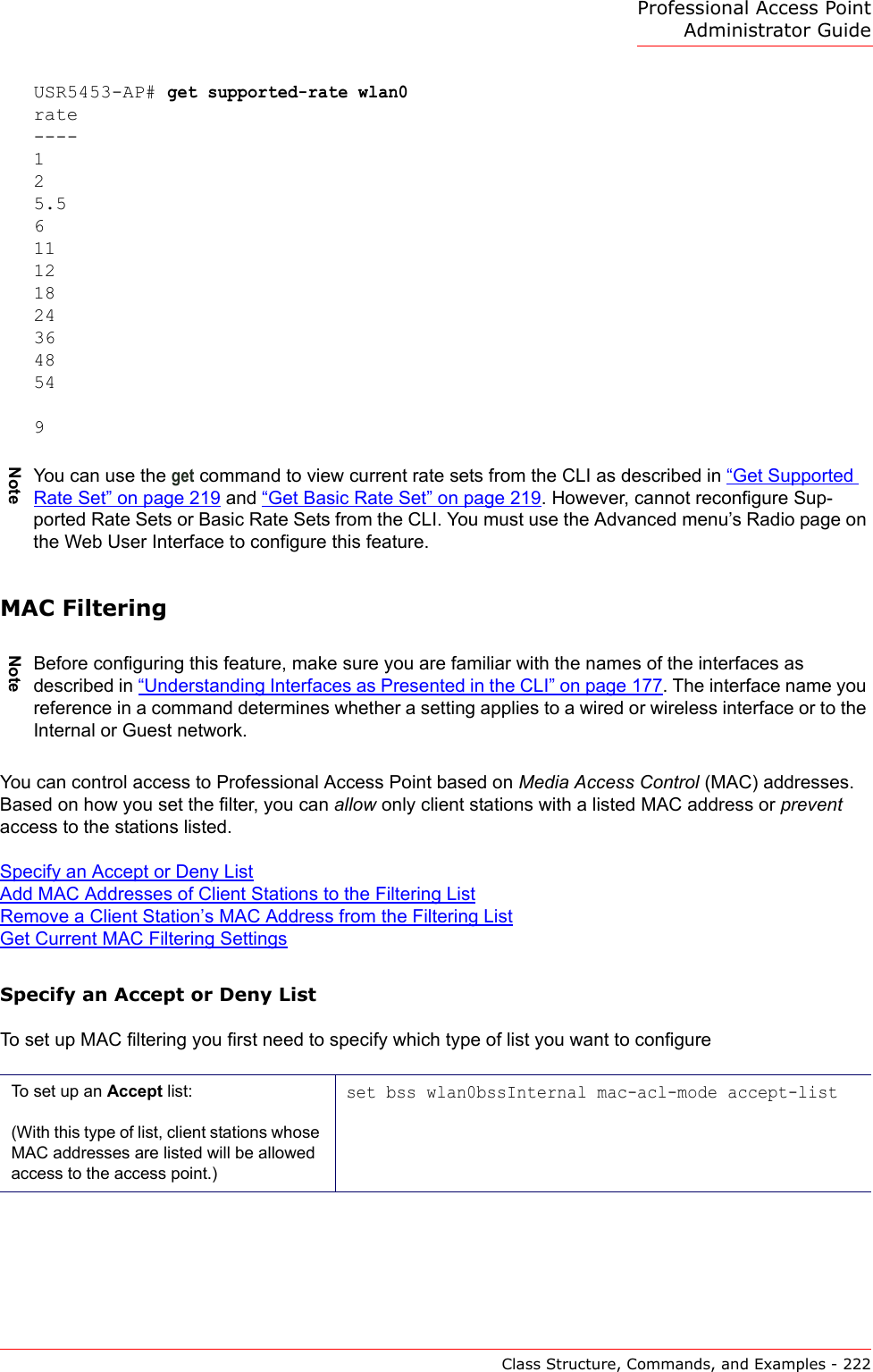
![Professional Access Point Administrator GuideClass Structure, Commands, and Examples - 219wme onGet Supported Rate SetThe Supported Rate Set is what the access point supports. The access point will automatically choose the most efficient rate based on factors like error rates and distance of client stations from the access point.USR5453-AP# get supported-ratename rate-----------wlan0 54wlan0 48wlan0 36wlan0 24wlan0 18wlan0 12wlan0 11wlan0 9wlan0 6wlan0 5.5wlan0 2wlan0 1Get Basic Rate SetThe Basic Rate Set is what the access point will advertise to the network for the purposes of setting up communication with other APs and client stations on the network. It is generally more efficient to have an access point broadcast a subset of its supported rate sets.USR5453-AP# get basic-ratename rate-----------wlan0 11wlan0 5.5wlan0 2wlan0 1Configure Radio Settings1. Turn the Radio On or Off 2. Set the Radio Mode 3. Enable or Disable Super G 4. Set the Beacon Interval 5. Set the DTIM Period 6. Set the Fragmentation Threshold 7. Set the RTS Threshold 8. Configure Basic and Supported Rate SetsNoteTo get a list of all fields you can set on the access point radio, type the following at the CLI prompt: set radio wlan0 [SpaceKey] [TAB] [TAB]](https://usermanual.wiki/Cameo-Communications/USR5453.Manual-2/User-Guide-628651-Page-65.png)
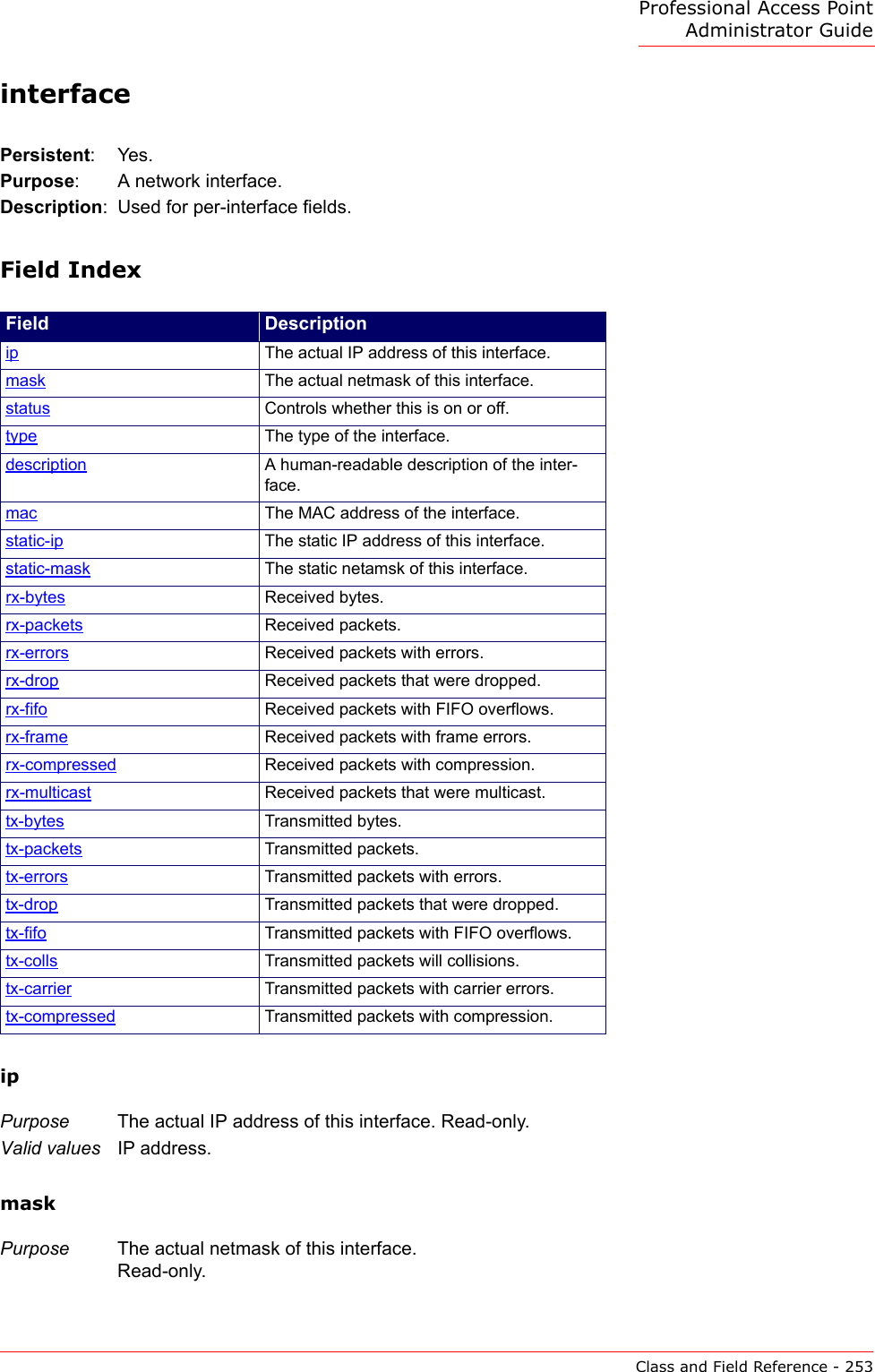
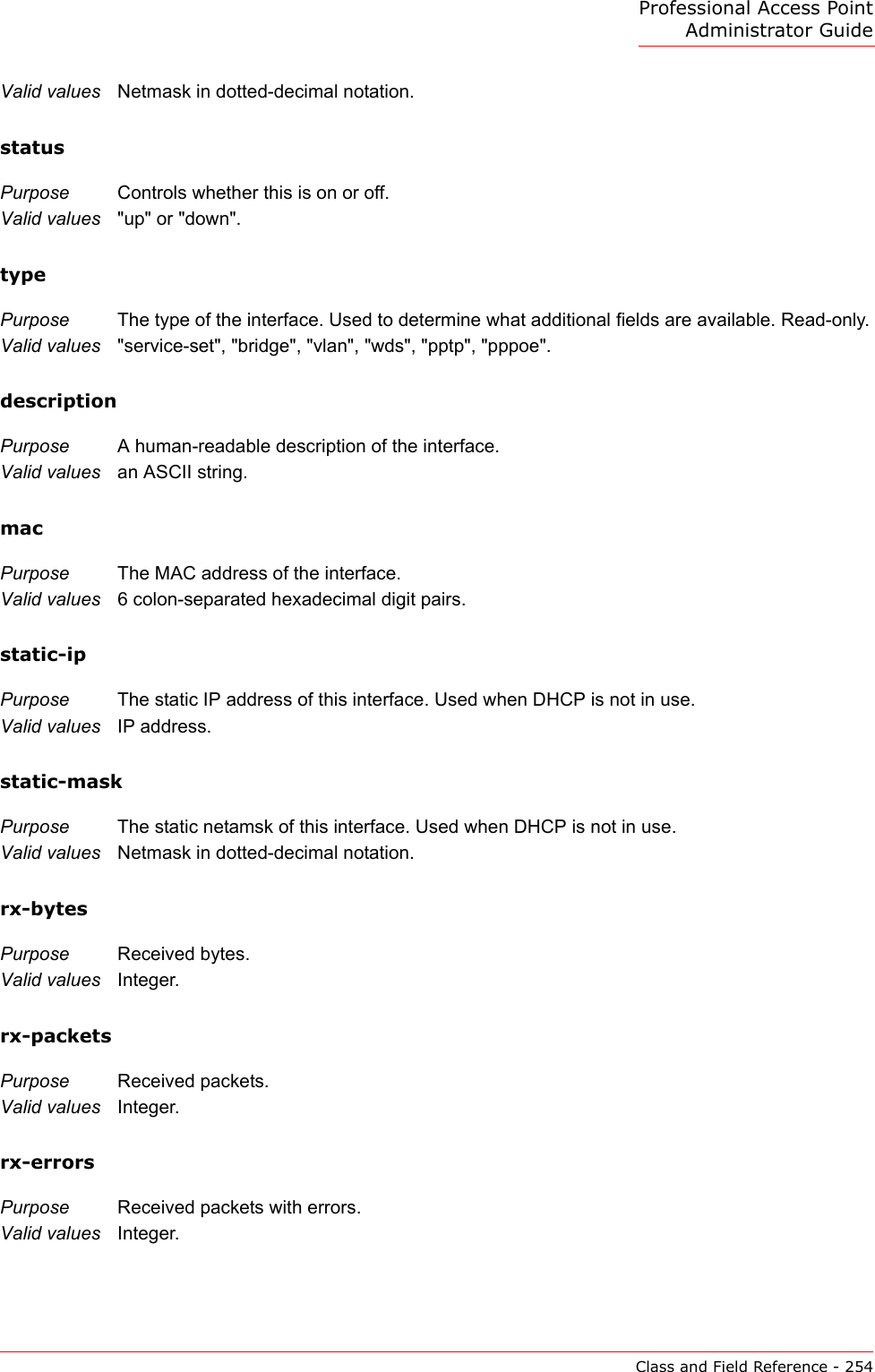
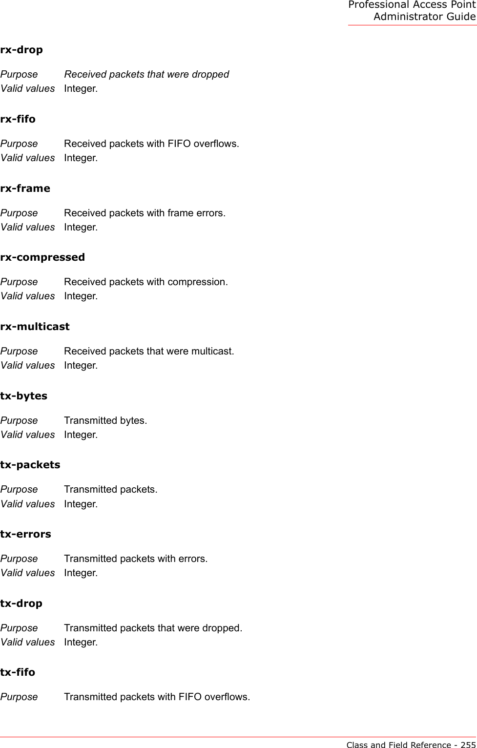
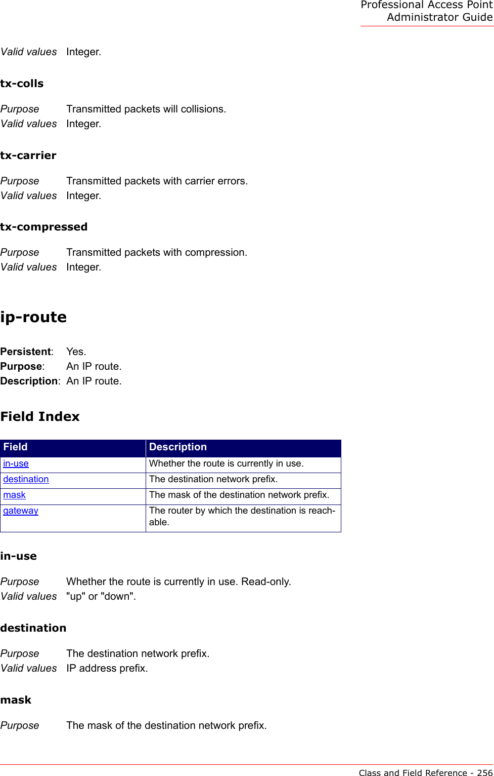
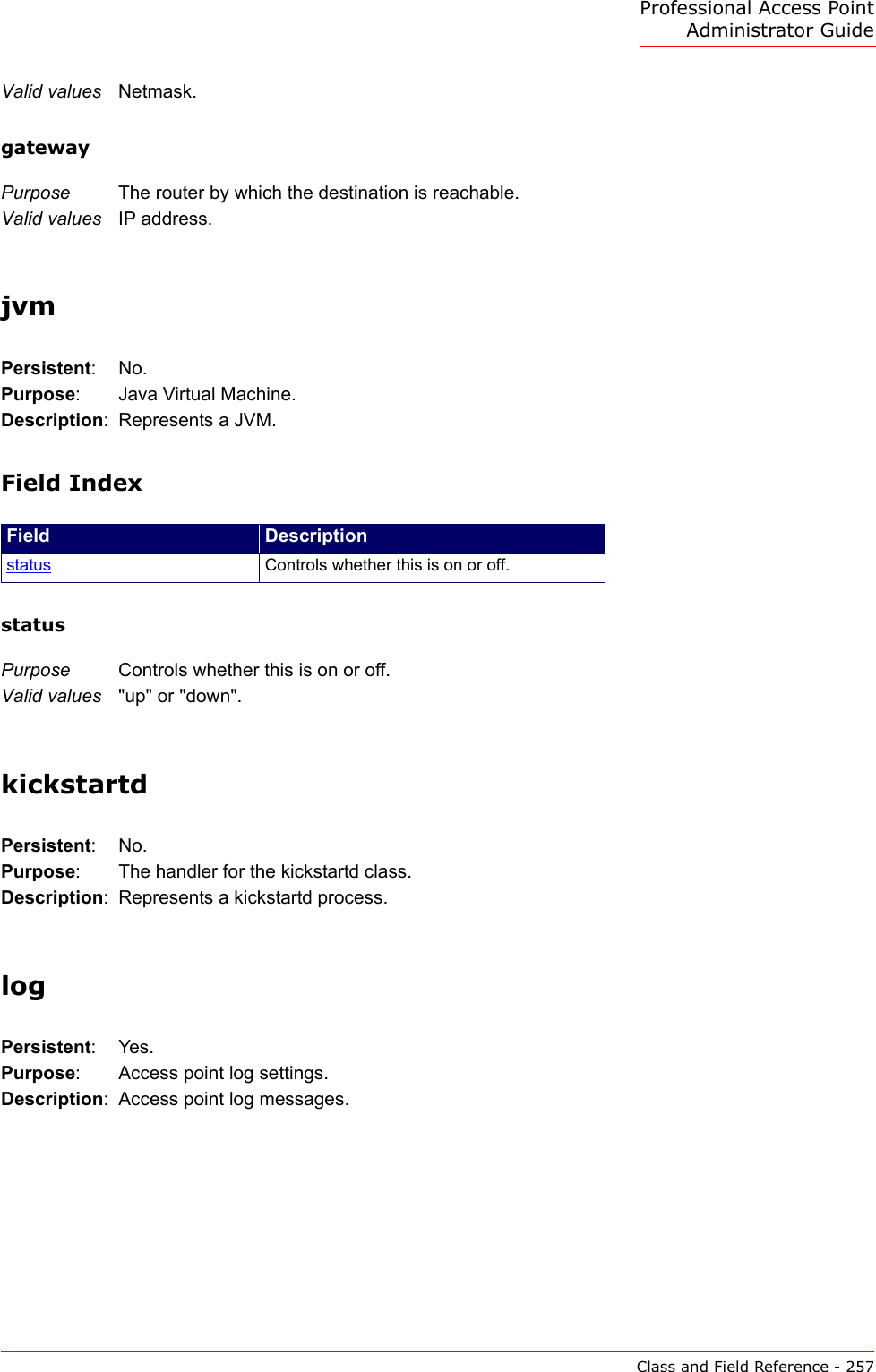
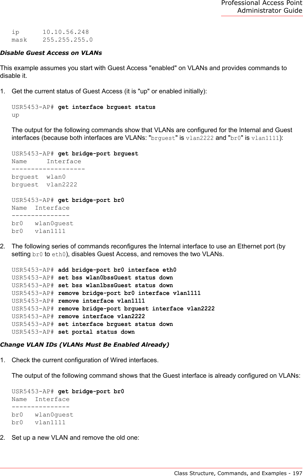
![Professional Access Point Administrator GuideClass and Field Reference - 252Field Indexdns-[12]Purpose Domain name servers in use.Valid values IP address.domain Purpose Domain name in use.Valid values DNS domain name.idpurpose The host name.Valid values DNS domain name.static-dns-[12]Purpose Domain name servers to use when not obtained through DHCP.Valid values IP address.static-domainPurpose Domain name to use when not obtained through DHCP.Valid values DNS domain name.dns-via-dhcpPurpose Whether DNS parameters are obtained through DHCP.Valid values "up" or "down".Field Descriptiondns-[12] Domain name servers in use.domain Domain name in use.id The host name.static-dns-[12] Domain name servers to use when not obtained through DHCP.static-domain Domain name to use when not obtained through DHCP.dns-via-dhcp Whether DNS parameters are obtained through DHCP.](https://usermanual.wiki/Cameo-Communications/USR5453.Manual-2/User-Guide-628651-Page-98.png)