Cameo Communications WLAG1302 802.11a/b/g mini PCI Adapter User Manual WLAG 1302 FCC DGT
Cameo Communications Inc 802.11a/b/g mini PCI Adapter WLAG 1302 FCC DGT
UserManual.wiki
>
Cameo Communications
>
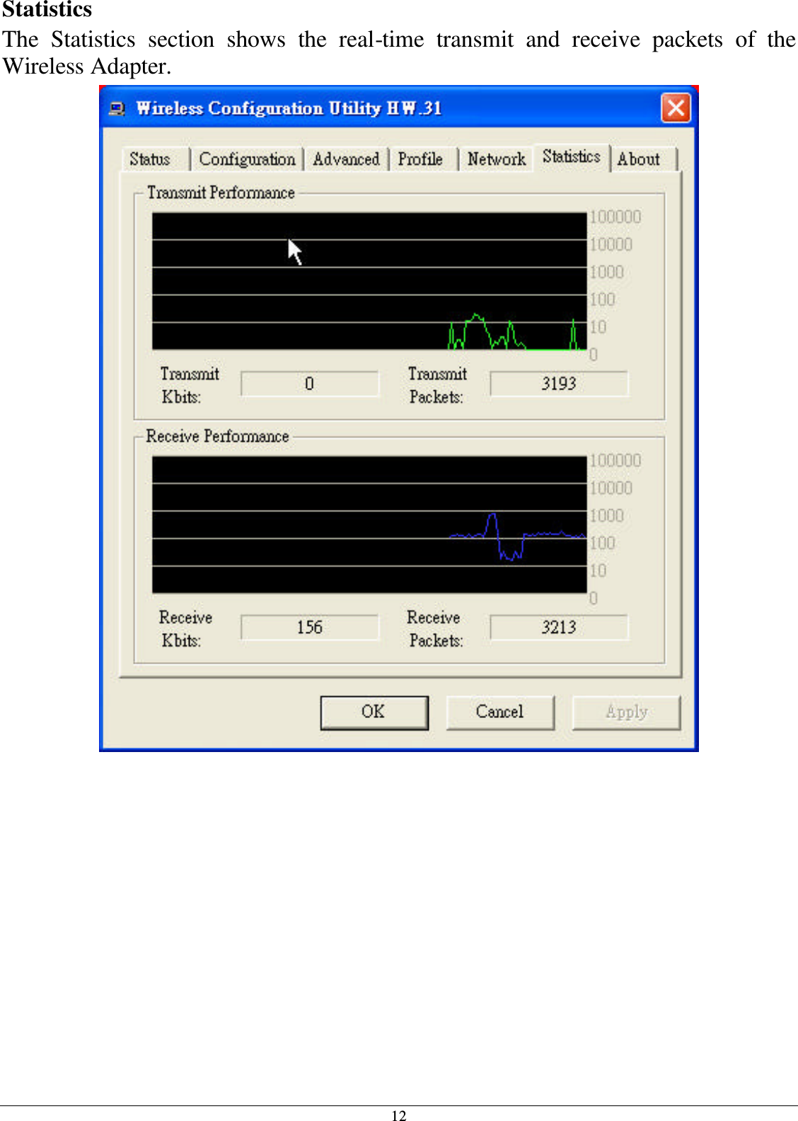
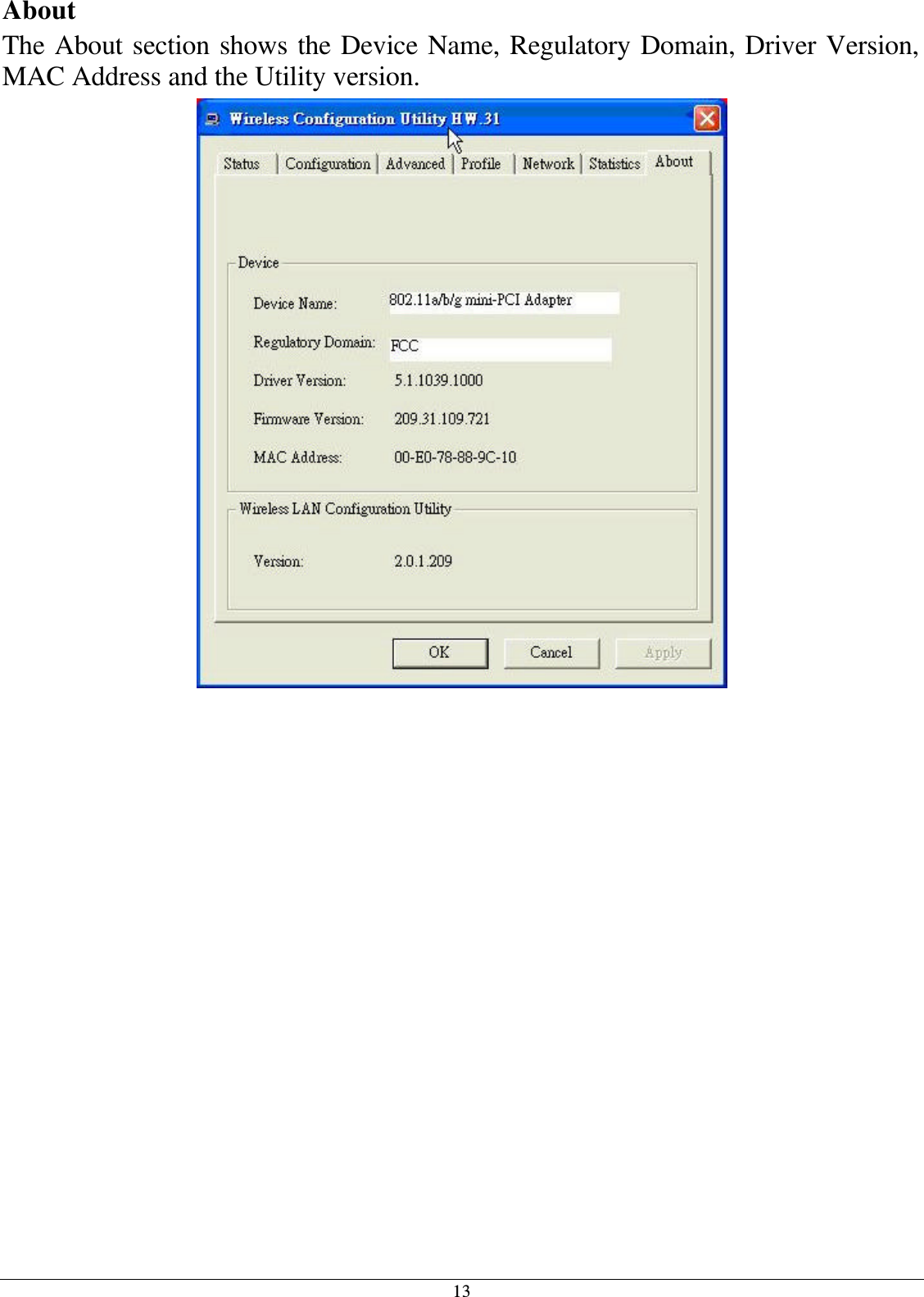
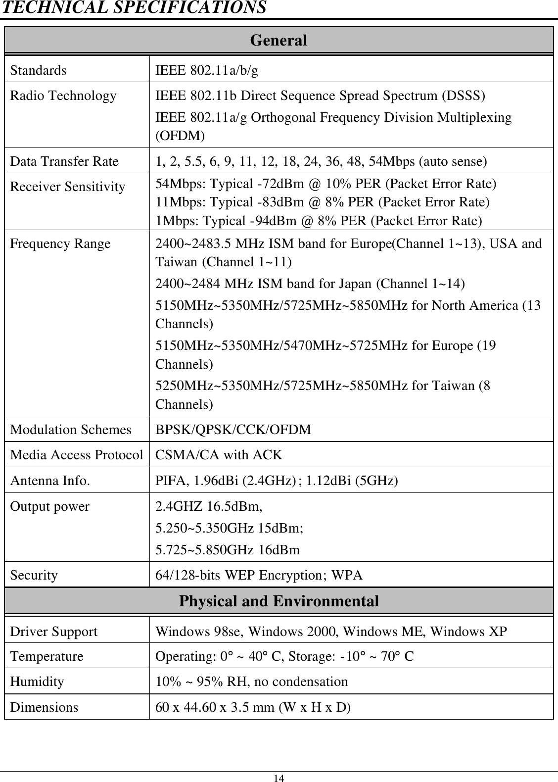
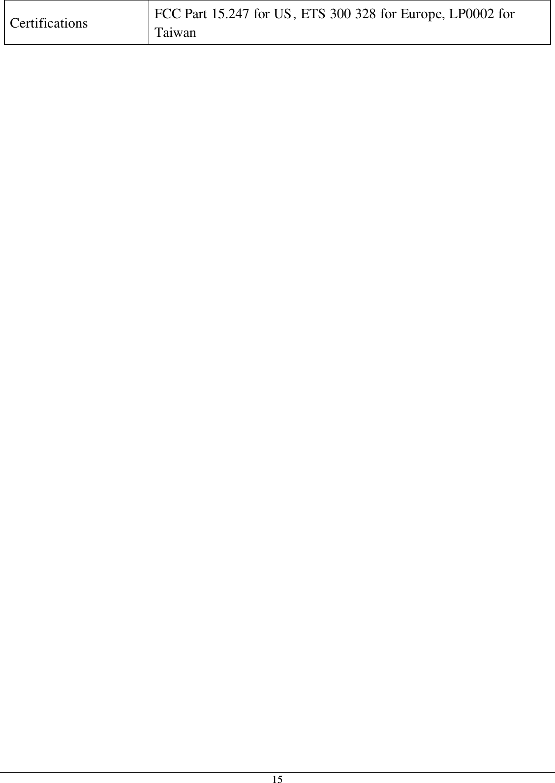
WLAG1302 User Manual
Manual
Navigation menu
Upload a User Manual
Namespaces
Wiki Guide
HTML
PDF
Info
Views
User Manual
Discussion / Help
Navigation