Cameo Communications WLAG1302 802.11a/b/g mini PCI Adapter User Manual WLAG 1302 FCC DGT
Cameo Communications Inc 802.11a/b/g mini PCI Adapter WLAG 1302 FCC DGT
Manual
802.11a/b/g
mini PCI Adapter
CAMEO WLAG-1302 User’s Guide

i
Regulatory notes and statements
Federal Communication Commission Interference Statement
This equipment has been tested and found to comply with the limits for a Class B
digital device, pursuant to Part 15 of the FCC Rules. These limits are designed to
provide reasonable protection against harmful interference in a residential
installation. This equipment generate, uses and can radiate radio frequency energy
and, if not installed and used in accordance with the instructions, may cause
harmful interference to radio communications. However, there is no guarantee that
interference will not occur in a particular installation. If this equipment does cause
harmful interference to radio or television reception, which can be determined by
turning the equipment off and on, the user is encouraged to try to correct the
interference by one of the following measures:
- Reorient or relocate the receiving antenna.
- Increase the separation between the equipment and receiver.
- Connect the equipment into an outlet on a circuit different from that to which
the receiver is connected.
- Consult the dealer or an experienced radio/TV technician for help.
This device complies with Part 15 of the FCC Rules. Operation is subject to the
following two conditions: (1) This device may not cause harmful interference, and
(2) this device must accept any interference received, including interference that
may cause undesired operation.
FCC Caution: Any changes or modifications not expressly approved by the party
responsible for compliance could void the user's authority to operate this equipment.
IMPORTANT NOTE:
FCC Radiation Exposure Statement:
This equipment complies with FCC radiation exposure limits set forth for an
uncontrolled environment. This equipment should be installed and operated with
minimum distance 20cm between the radiator & your body.
This device is intended only for OEM integrators under the following conditions:
1) The antenna must be installed such that 20 cm is maintained between the antenna
and users, and
2) The antenna should be integral if the end device is intended to be operated in
5.15 ~ 5.25GHz frequency range.
As long as 2 conditions above are met, further transmitter test will not be required.
However, the OEM integrator is still responsible for testing their end-product for
any additional compliance requirements required with this module installed (for
example, digital device emissions, PC peripheral requirements, etc.).

ii
IMPORTANT NOTE: In the event that these conditions can not be met (for
example certain laptop configurations or co-location with another transmitter), then
the FCC authorization is no longer considered valid and the FCC ID can not be
used on the final product. In these circumstances, the OEM integrator will be
responsible for re-evaluating the end product (including the transmitter) and
obtaining a separate FCC authorization. The availability of some specific channels
and/or operational frequency bands are country dependent and are firmware
programmed at the factory to match the intended destination. The firmware setting
is not accessible by the end user.
End Product Labeling
This transmitter module is authorized only for use in device where the antenna may
be installed such that 20 cm may be maintained between the antenna and users (for
example: Notebook, etc.). The final end product must be labeled in a visible area
with the following: “Contains TX FCC ID: NHPWLAG1302”.
Manual Information That Must be Included
The OEM integrator has to be aware not to provide information to the end user
regarding how to install or remove this RF module in the user’s manual of the end
product which integrates this module.
The users manual for OEM integrators end users must include the following
information in a prominent location “IMPORTANT NOTE: To comply with FCC
RF exposure compliance requirements, the antenna used for this transmitter must be
installed to provide a separation distance of at least 20 cm from all persons and
must not be co-located or operating in conjunction with any other antenna or
transmitter”.
If the end product integrating this module is going to be operated in 5.15 ~
5.25GHz frequency range, the warning statement in the user manual of the end
product should include the restriction of operating this device in indoor could void
the user’s authority to operate the equipment.
This product is limited in CH1-CH11 for 2.4G band by specific firmware controlled
by the manufacturer and is not user changeable. The antenna(s) used for this
transmitter must be installed to provide a separation distance of at least 20 cm from
all persons and must not be co-located or operating in conjunction with any other
antenna or transmitter. The availability of some specific channels and/or operational
frequency bands are country dependent and are firmware programmed at the
factory to match the intended destination. The firmware setting is not accessible by
the end user.

iii
CE Mark Warning
This is a Class B product. In a domestic environment, this product may cause radio
interference, in which case the user may be required to take adequate measures.
Protection requirements for health and safety – Article 3.1a
Testing for electric safety according to EN 60950 has been conducted. These are
considered relevant and sufficient.
Protection requirements for electromagnetic compatibility – Article
3.1b
Testing for electromagnetic compatibility according to EN 301 489-1, EN 301 489-
17 and EN 55024 has been conducted. These are considered relevant and sufficient.
Effective use of the radio spectrum – Article 3.2
Testing for radio test suites according to EN 300 328 has been conducted. These are
considered relevant and sufficient.
CE in which Countries where the product may be used freely:
Germany, UK, Italy, Spain, Belgium, Netherlands, Portugal, Greece, Ireland,
Denmark, Luxembourg, Austria, Finland, Sweden, Norway and Iceland.
France: except the channel 10 through 13, law prohibits the use of other channels.
使用本產品之系統製造商請於設備上標示本產品內含射頻模組:
XXXyyyLPDzzzz-x"
經型式認證合格之低功率射頻電機,非經許可,公司、商號或使用者均不得
擅自變更頻率、加大功率或變更原設計之特性及功能。
低功率射頻電機之使用不得影響飛航安全及干擾合法通信;經發現有干擾現
象時,應立即停用,並改善至無干擾時方得繼續使用。前項合法通信,指依
電信法規定作業之無線電通信。低功率射頻電機須忍受合法通信或工業、科
學及醫療用電波輻射性電機設備之干擾。
工作頻率 5.250 ~ 5.350GHz 該頻段限於室內使用

iv

v
TABLE OF CONTENT
Introduction.........................................................................................1
Overview of this User’s Guide ........................................................1
Software Installation...........................................................................2
Windows 98se/ME/2000/XP Utility and Driver Installation.........2
Wireless Utility Setting....................................................................4
Technical Specifications ..................................................................14

1
INTRODUCTION
Congratulations on your purchase of this 802.11a/b/g mini-PCI Adapter.
This manual helps to get familiar with the Wireless mini PCI Adapter. This manual
contains detailed instructions in operation of this product. Please keep this manual
for future reference.
With a the 802.11a/b/g mini PCI Adapter, a desktop or laptop computer can
communicate with another computer in a wireless way. Easy-to-use utilities are
bundled with Wireless mini-PCI Adapter for configuration, monitoring, and
diagnosis purposes.
Wireless mini PCI Adapter can wirelessly transmit and receive data, minimizing the
need for wired connections, at a speed of up to fifty-four megabit per second.
Wireless mini PCI Adapter provides users with an access to real-time information
anywhere in their organization. The mobility provides productivity and service,
which are not available under wired networks. The Wireless mini PCI Adapter
configuration is easy to change from peer-to-peer networks, suitable for a small
number of users, to full infrastructure networks of thousands of users that allow
roaming around a broad area.
Overview of this User’s Guide
Introduction. Describes the Wireless mini PCI Adapter and its features.
Software Installation. Tells how to setup the driver and the utility setting.
Technical Specifications. Lists the technical (general, physical and environmental)
specifications of the Wireless mini PCI Adapter.
2
SOFTWARE INSTALLATION
This section will lead you to install the driver and utility of the 802.11a/b/g mini-
PCI Adapter Windows OS installation.
Windows 98se/ME/2000/XP Utility and Driver Installation
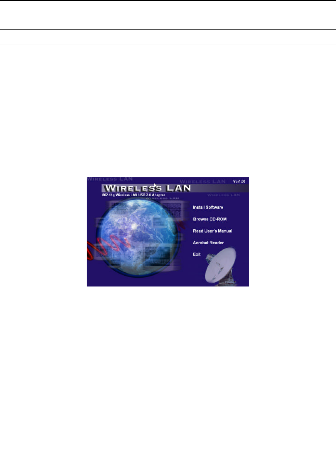
1. Insert the Wireless LAN mini PCI Adapter Driver & Utility CD-ROM into
computer’s CD-ROM Drive and it will automatically run a setup menu and
install the driver and the utility, for Win98se, please reboot the system to install
the driver to the system properly. In some specific setting on Windows system,
you may need to proceed the software manually, go to your Windows Start
menu and choose Run, type “D:\Utility\Setup.exe” in the dialog box (D:\ will
depend on where your CD-ROM drive is located) and click OK.
2. If you need to install the driver manually, refer each Windows OS to the
following CD-Rom directory path: D:\Drivers\<Windows OS>\SIS163U.INF.
Note: (D:\ will depends on where the CD-ROM drive is located and
<Windows OS> will depend on the Windows Operating System you are using).
3. The Install Shield Wizard screen will appear. Click “Next” to continue.
4. The installation program will help you to setup the Wireless Utility.
Be noted that the Windows XP have its own Wireless Utility; you can either
use the utility of Windows XP or the provided utility.

3
.
5. You will see the icon on the Windows task bar when you finish the installation.
When the icon in the toolbar represents in green color, it is properly connected
to the network and if it represents in red color, then it is not connected to the
network.
4
Wireless Utility Setting
With the 802.11a/b/g mini-PCI Adapter utility, users can configure all the functions
provided by the Wireless Monitor Utility. Double-click the utility icon that appears
in the taskbar.
The Wireless Monitor Utility includes seven tabs: Status, Configuration, Advanced,
Profile, Network, Statistics and About.
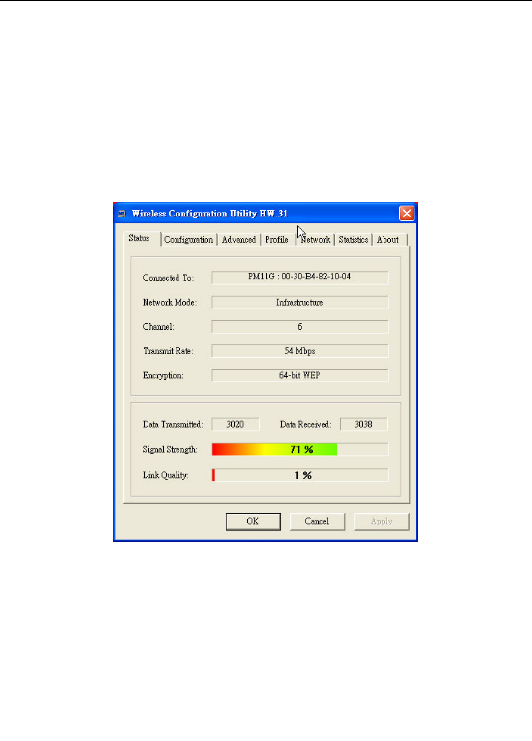
Status
The Status screen shows you the status of the Wireless Adapter, it shows that where
the device is connected to, the Network mode, the Channel, the transmit rate and
the encryption mode.
There are two dialog boxes showing the data transmitted and the data received. The
two signal lines show the Signal Strength and the Link Quality of the device.
5
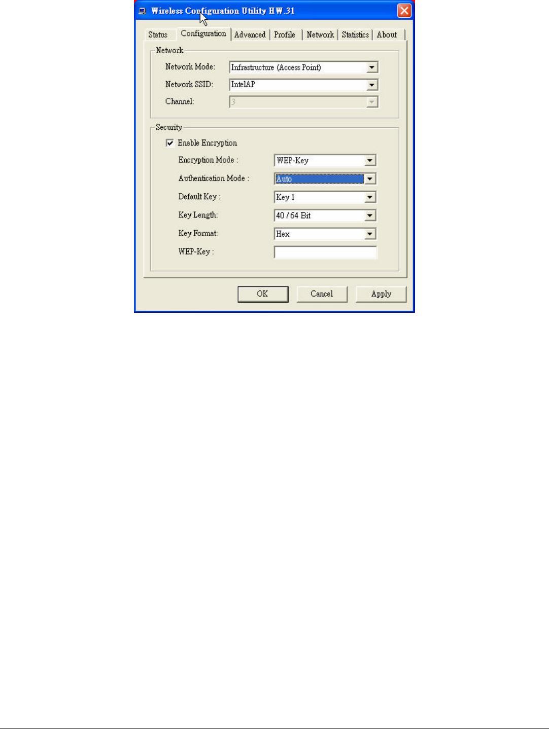
Configuration
The Configuration function helps you to configure the Network and the Security.
Network: the setting of the Network mode, the SSID and the Channels.
Ø Network Mode:
If you want to connect with an Access Point, please set to “Infrastructure” mode. If
you have more stations and just want to set them as local network, please set the
mode to “Ad-Hoc” mode.
Ø Network SSID:
The SSID differentiates one Wireless LAN group name from another; so all access
points and all devices attempting to connect to a specific Wireless LAN group
name must use the same SSID. A device will not be permitted to join the BSS
unless it can provide the unique SSID.
If the SSID parameter is “ANY”, it will detect the strongest signal of the wireless
station.
Ø Channel:
It shows radio channel numbers that used for Wireless LAN networking.
The channel number can be set only under the Ad-Hoc operation mode. In Ad-Hoc
mode stations, each station must have the same channel numbers and SSID.
In Infrastructure mode, the Wireless mini-PCI Adapter will automatically detect the
channel number of the Access Point.
Security: the setting of the Network Encryption.
This function is used to protect wireless communication from eavesdropping. A
secondary function of encryption is to prevent unauthorized access to a wireless
network, and it can be achieved by using the Encryption function.

6
Ø Encryption Mode:
There are two kinds of encryption mode, WEP encryption and WPA-PSK.
Click the Enable Encryption to activate the security of the mini-PCI Adapter.
WEP-Key: WEP (Wired Equivalent Privacy) relies on a secret key that is
shared between a mobile station and a base station (Access Point).
WEP-Passphrase: the Passphrase in the dialog box helps you to create a
group of WEP key in the Key Setting.
Ø Authentication Mode:
Open System: with the same WEP key between the stations, the stations
don’t need to be authenticated, and this algorithm was set to default.
Shared Key: with the same WEP key between the stations in this
Authentication algorithm, this type will use packets with encryption by
transferring a challenge text which will be acknowledge by both side of the
stations. In order to choose which authentication algorithm will be used, you
must know which one the station supports this algorithm first.
It is recommended to select “Auto” if you are not familiar with the setting.
Ø Default Key (Key 1 ~ Key 4):
You can type the key that you want to use from Key#1 to Key #4, and the key that
you type will be the encryption between the stations that you connected with.
Ø Key Length, Key Format and WEP Key:
If you select 64bit in Hex format, you must type 10 values in the following range
(0~F, hexadecimal), or 64bit in ASCII format, you must type 5 values in the
following range (0~9, A~Z and a~z Alphanumeric).
If you select 128bit in Hex format, you must type 26 values (0~F, hexadecimal), or
128bit in ASCII format, you must type 13 values in the following range (0~9, A~Z
and a~z Alphanumeric).
Be sure that the mini-PCI Adapter and the wireless station were set in the same key.
Note: After all the settings are completed, click Apply to save the setting.
7
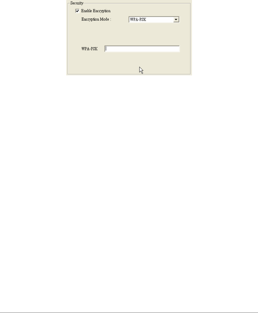
WPA-PSK: WPA-PSK (Wi-Fi Protected Access pre-shared key) is a simpler
version that does not support 802.1x and requires a separate RADIUS server for
mutual authentication.
Enter a Passphrase in the WPA-PSK dialog box. This passphrase must be the same
on each computer that is connected to the wireless network.
8
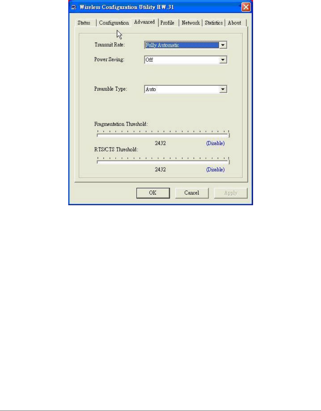
Advanced
The Advanced settings help you to control the Wireless Adapter to adjust with
wireless devices in certain environment.
Ø Transmit Rate:
You can choose one of the transmission rates as follows, 54Mbps, 48Mbps,
36Mbps, 24Mbps, 18Mbps, 12Mbps, 11Mbps, 9Mbps, 6Mbps, 5.5Mbps, 2Mbps,
1Mbps, and Fully Automatic. The Fully Automatic will automatically detect the
suitable linking transfer rate and auto fall back when the signal is not too strong to
transmit data, it will auto fall back from 54Mbps to 1 Mbps.
Ø Power Saving:
To set your Wireless Adapter as power saving mode, select “Off”, “Normal” or
“Maximum”.

9
Ø Preamble Type:
The usage of the preamble is to limit the packet size of the data to transmit. It is
recommended to choose the short preamble when the link quality is bad, it is to
prevent the wasting time of resending a long packet that is lost. The Default is Auto
which access short and long preamble.
Ø Fragment Threshold:
Fragmentation Threshold is a way of transmitting the packets that will be
fragmented. Choose a setting within a range of 256 to 2432 bytes. It is
recommended to fragment the packet when the link quality is bad, it is to prevent
the wasting time of resending a long packet that is lost.
Ø RTS/CTS Threshold:
The RTS/CTS Threshold is a station initiates the process by sending a RTS frame,
the other ends receives the RTS and responds with a CTS frame, the station must
receive a CTS frame before sending the data frame. This is to prevent the collisions
by each station. Choose a setting within a range of 256 to 2432 bytes. It is
recommended limiting a long packet to prevent each station waiting too long to
transmit a data.
10
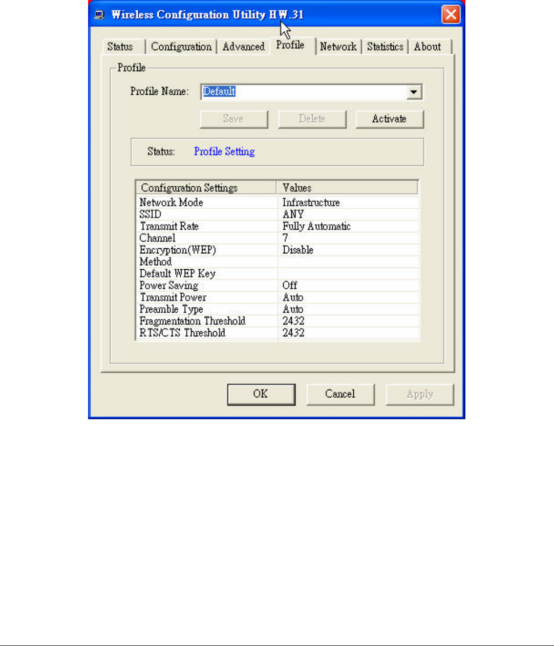
Profile
The Profile section allows you to set values for all parameters by selecting a
previously defined profile. Type a name in the Profile Name field to create a profile,
click “Save” and then click “Apply” when a profile is done. You can click “Delete”
if the profile is no longer used, to activate other profile, choose a profile name in
the Profile Name field and click Activate.
11
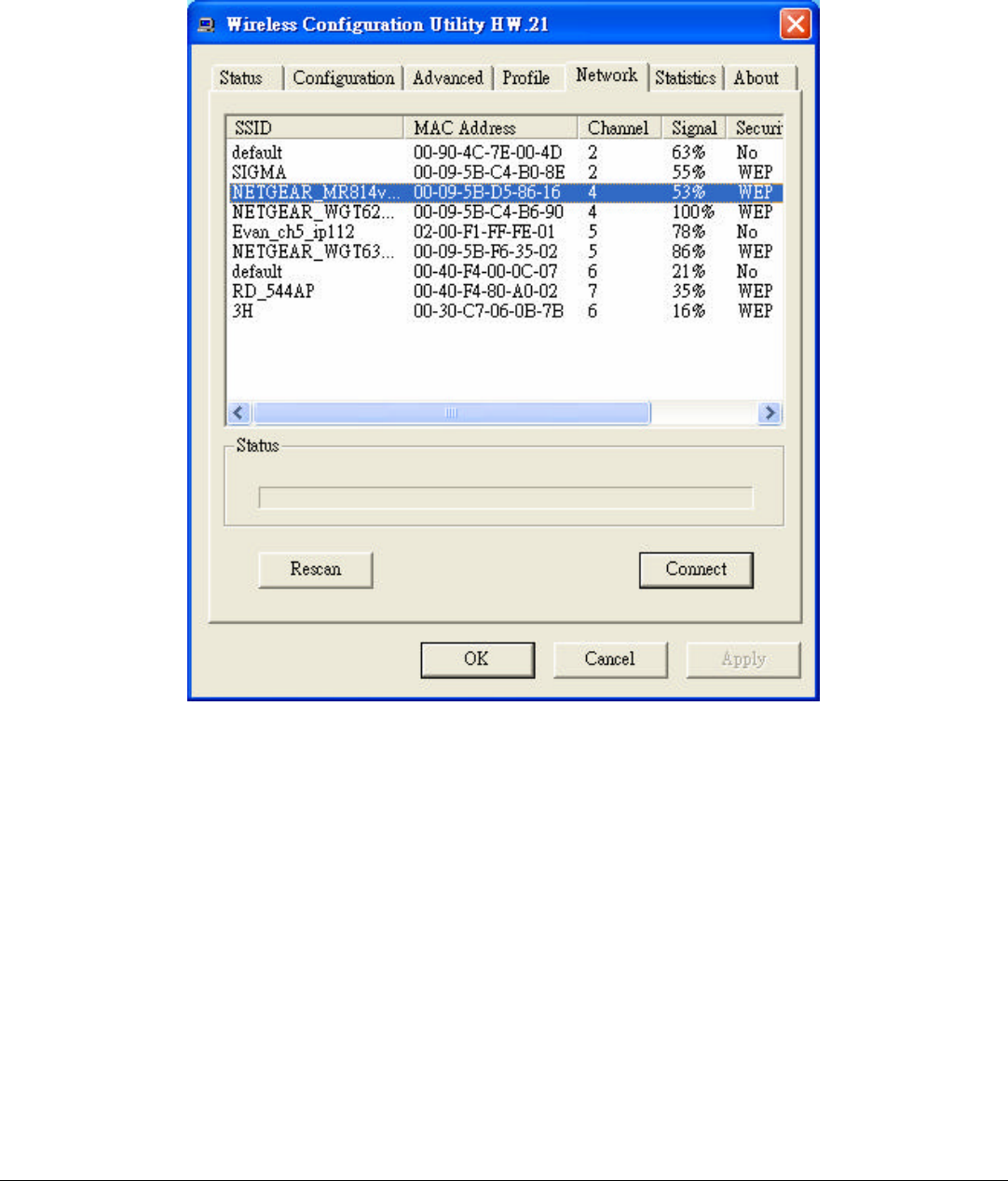
Network
The screen shows all the Wireless devices around your Wireless Adapter. The
information of the wireless devices includes the SSID, MAC Address, Channels,
Signal, the Security type and the Network mode.
You can click the “Rescan” button to find the new wireless devices, and double-
click the device to choose the wireless station that you want to connect with.
12
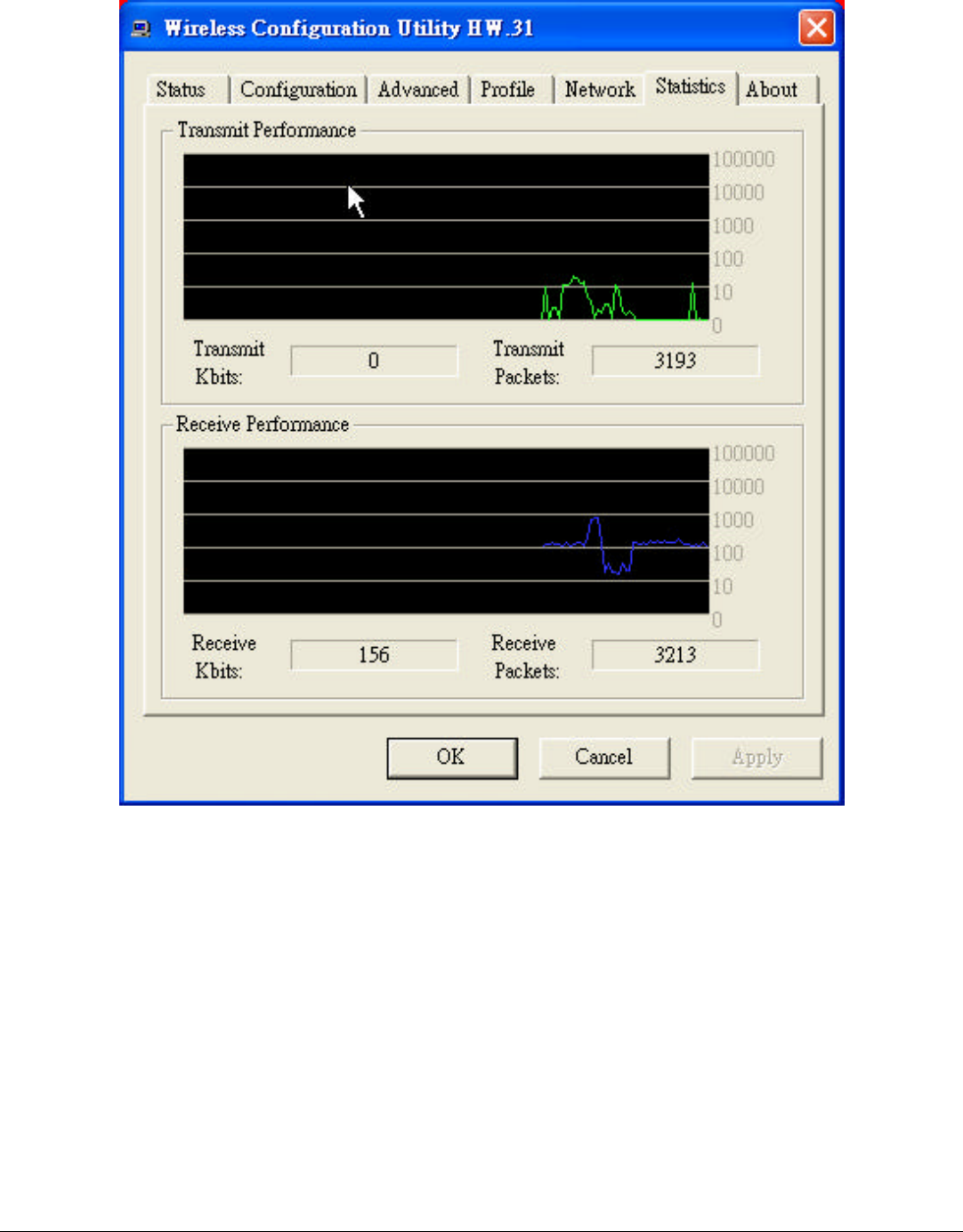
Statistics
The Statistics section shows the real-time transmit and receive packets of the
Wireless Adapter.
13
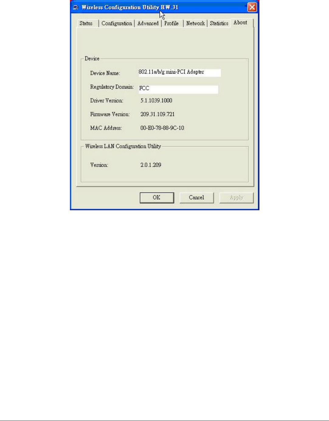
About
The About section shows the Device Name, Regulatory Domain, Driver Version,
MAC Address and the Utility version.

14
TECHNICAL SPECIFICATIONS
General
Standards IEEE 802.11a/b/g
Radio Technology IEEE 802.11b Direct Sequence Spread Spectrum (DSSS)
IEEE 802.11a/g Orthogonal Frequency Division Multiplexing
(OFDM)
Data Transfer Rate 1, 2, 5.5, 6, 9, 11, 12, 18, 24, 36, 48, 54Mbps (auto sense)
Receiver Sensitivity 54Mbps: Typical -72dBm @ 10% PER (Packet Error Rate)
11Mbps: Typical -83dBm @ 8% PER (Packet Error Rate)
1Mbps: Typical -94dBm @ 8% PER (Packet Error Rate)
Frequency Range 2400~2483.5 MHz ISM band for Europe(Channel 1~13), USA and
Taiwan (Channel 1~11)
2400~2484 MHz ISM band for Japan (Channel 1~14)
5150MHz~5350MHz/5725MHz~5850MHz for North America (13
Channels)
5150MHz~5350MHz/5470MHz~5725MHz for Europe (19
Channels)
5250MHz~5350MHz/5725MHz~5850MHz for Taiwan (8
Channels)
Modulation Schemes BPSK/QPSK/CCK/OFDM
Media Access Protocol
CSMA/CA with ACK
Antenna Info. PIFA, 1.96dBi (2.4GHz); 1.12dBi (5GHz)
Output power 2.4GHZ 16.5dBm,
5.250~5.350GHz 15dBm;
5.725~5.850GHz 16dBm
Security 64/128-bits WEP Encryption; WPA
Physical and Environmental
Driver Support Windows 98se, Windows 2000, Windows ME, Windows XP
Temperature Operating: 0° ~ 40° C, Storage: -10° ~ 70° C
Humidity 10% ~ 95% RH, no condensation
Dimensions 60 x 44.60 x 3.5 mm (W x H x D)

15
Certifications FCC Part 15.247 for US, ETS 300 328 for Europe, LP0002 for
Taiwan