Cameo Communications WLB2006 802.11b WIRLESS ACCESS POINT User Manual USERS MANUAL
Cameo Communications Inc 802.11b WIRLESS ACCESS POINT USERS MANUAL
UserManual.wiki
>
Cameo Communications
>
WLB2006 User Manual
USERS MANUAL
Navigation menu
Upload a User Manual
Namespaces
Wiki Guide
HTML
PDF
Info
Views
User Manual
Discussion / Help
Navigation

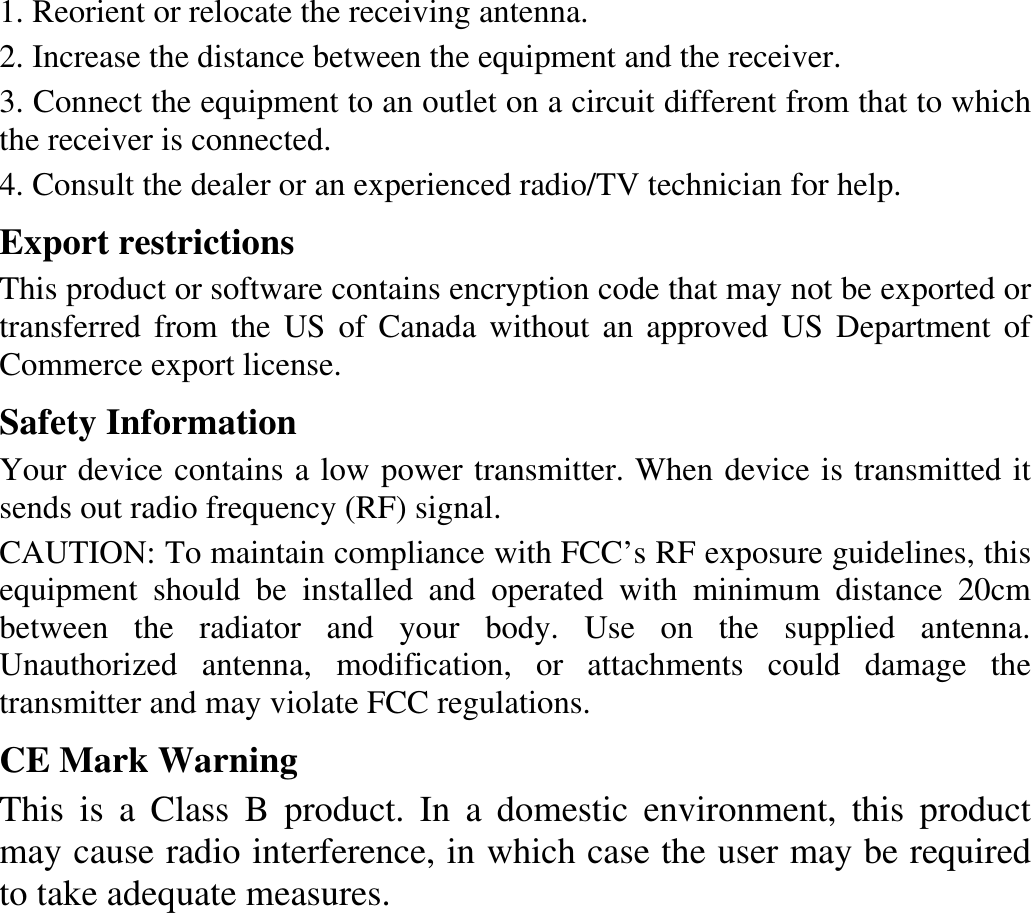
![Declaration of Conformity for R&TTE directive 1999/5/EC Essential requirements – Article 3 Protection requirements for health and safety – Article 3.1a Testing for electric safety according to EN 60950 has been conducted. These are considered relevant and sufficient. Protection requirements for electromagnetic compatibility – Article 3.1b Testing for electromagnetic compatibility according to EN 301 489-1 and EN 301 489-17 has been conducted. These are considered relevant and sufficient. Effective use of the radio spectrum – Article 3.2 Testing for radio test suites according to EN 300 328- 2 has been conducted. These are considered relevant and sufficient. Hereby, [CAMEO COMMUNICATIONS, INC.], declares that this [IEEE 802.11b Wireless Access Point] is in compliance with the essential requirements and other relevant provisions of Directive 1999/5/EC.”](https://usermanual.wiki/Cameo-Communications/WLB2006/User-Guide-375995-Page-6.png)