Cameo Communications WLG2008B 54Mbps Wireless LAN Pocket Access Point User Manual WLG 2008
Cameo Communications Inc 54Mbps Wireless LAN Pocket Access Point WLG 2008
UserManual.wiki
>
Cameo Communications
>
WLG2008B User Manual
>
Manual Part2
Contents
1.
Manual Part1
2.
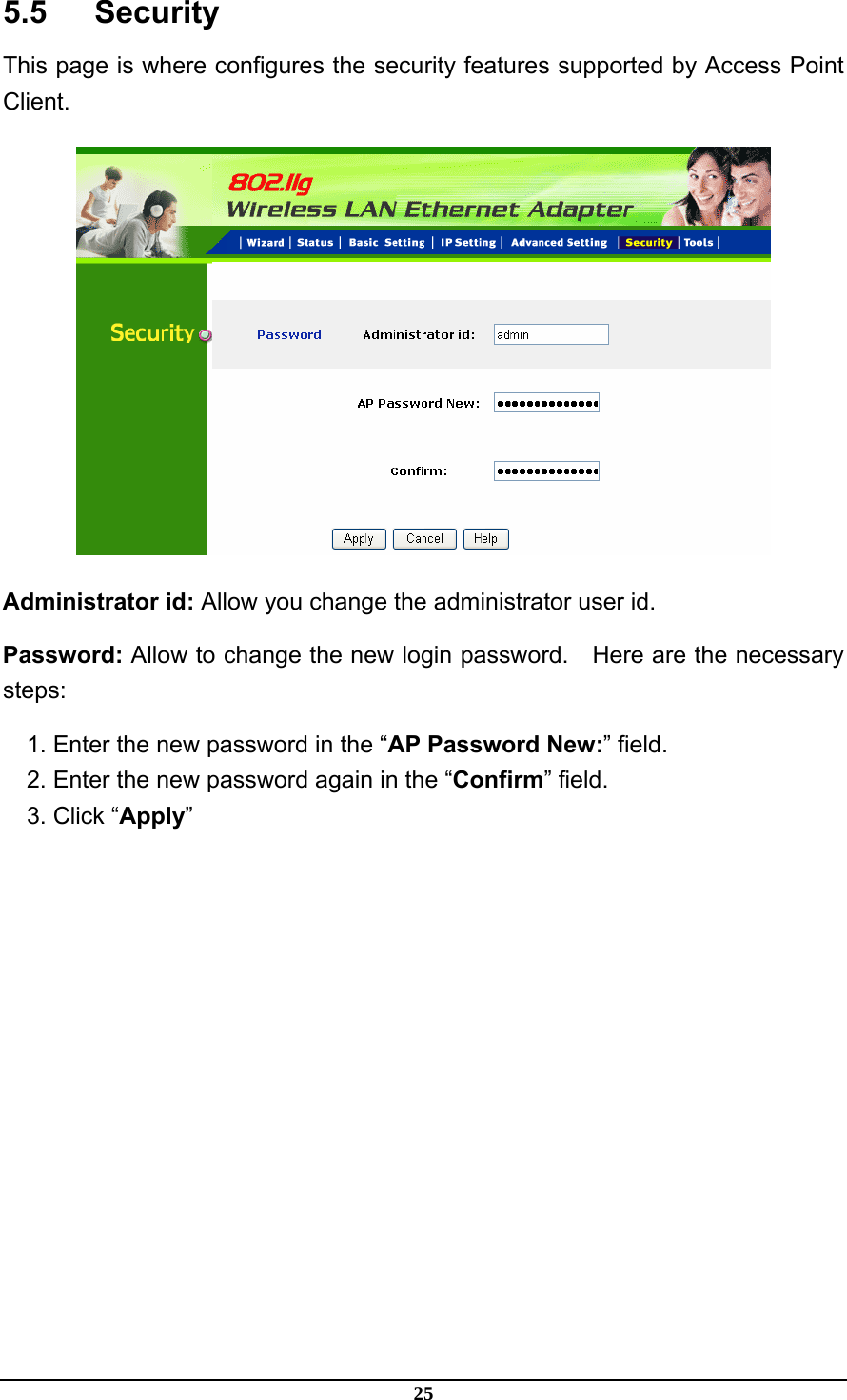
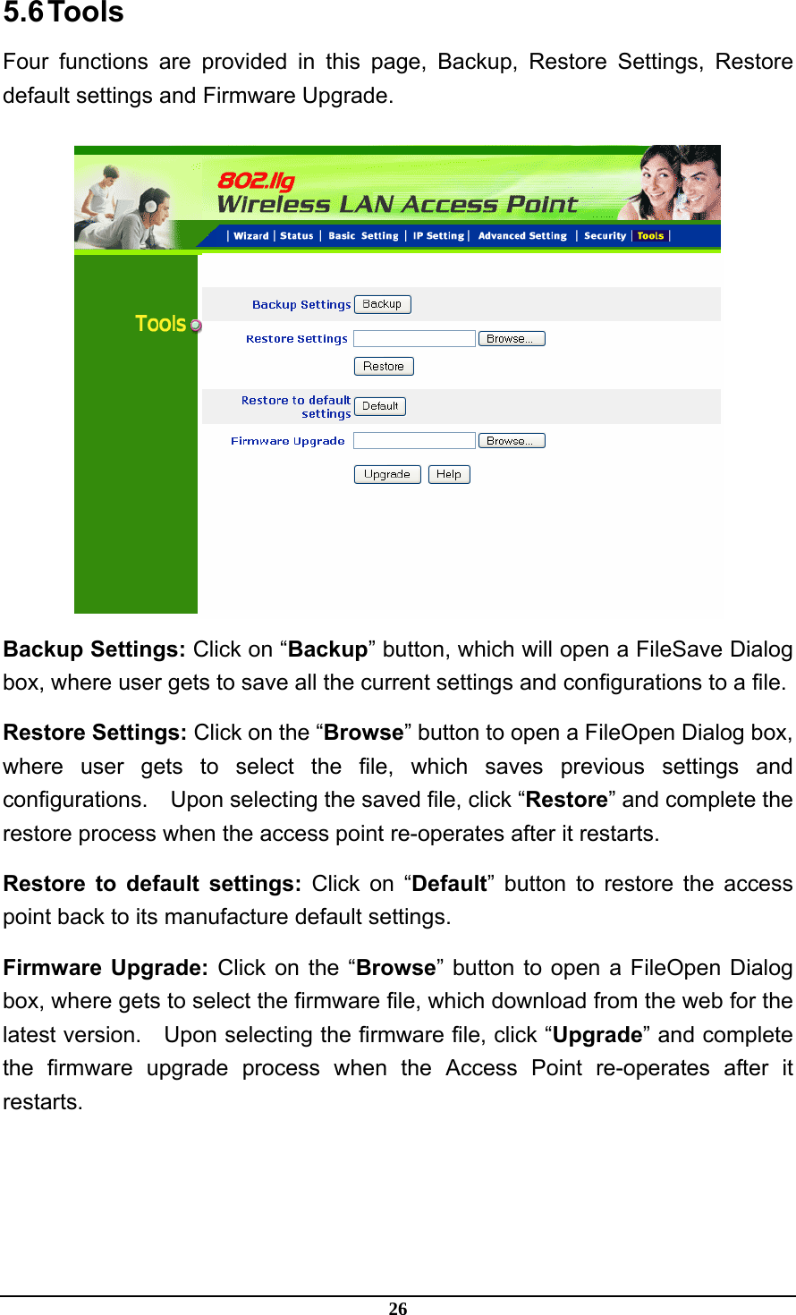
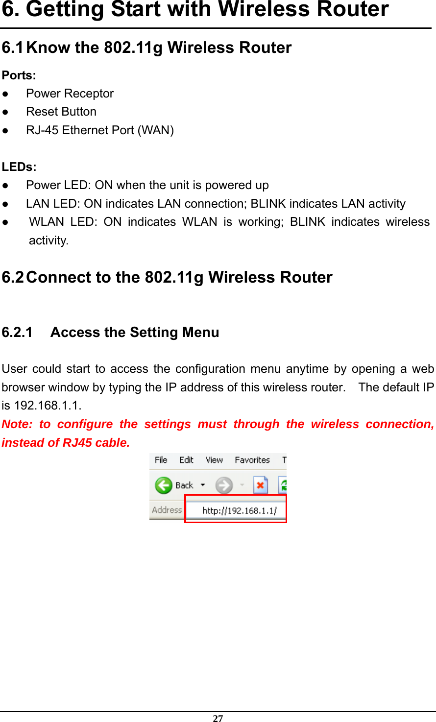
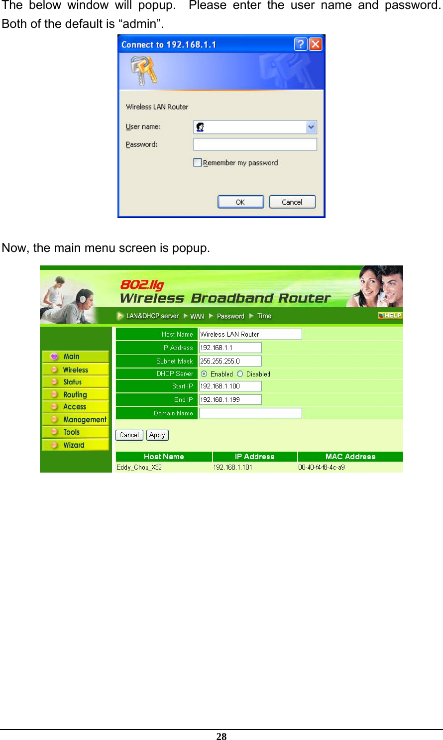
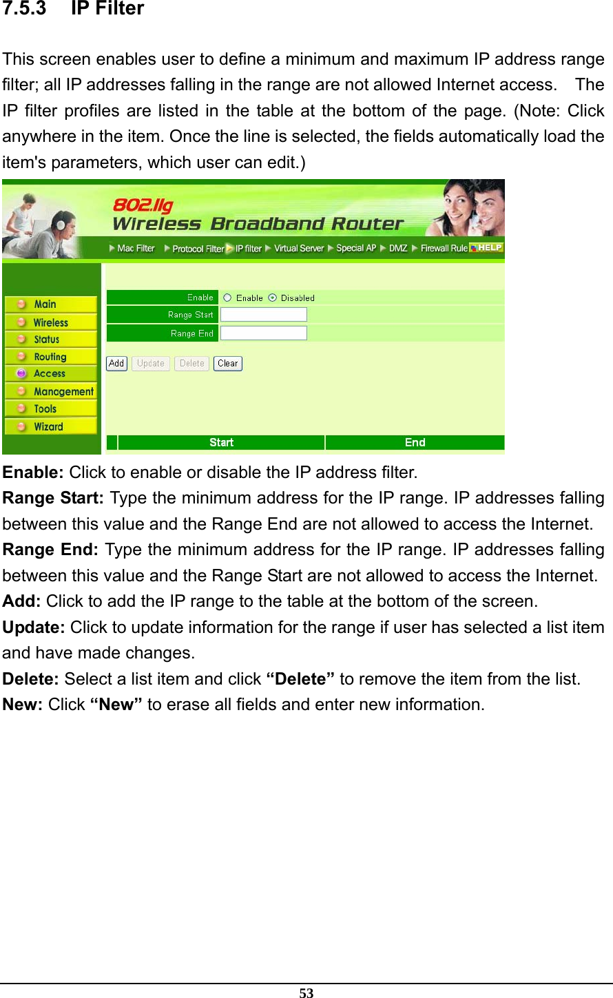
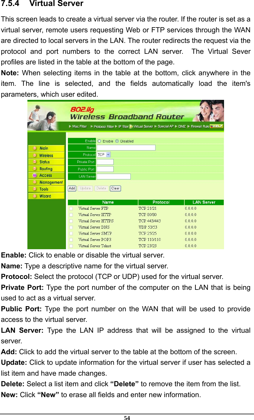
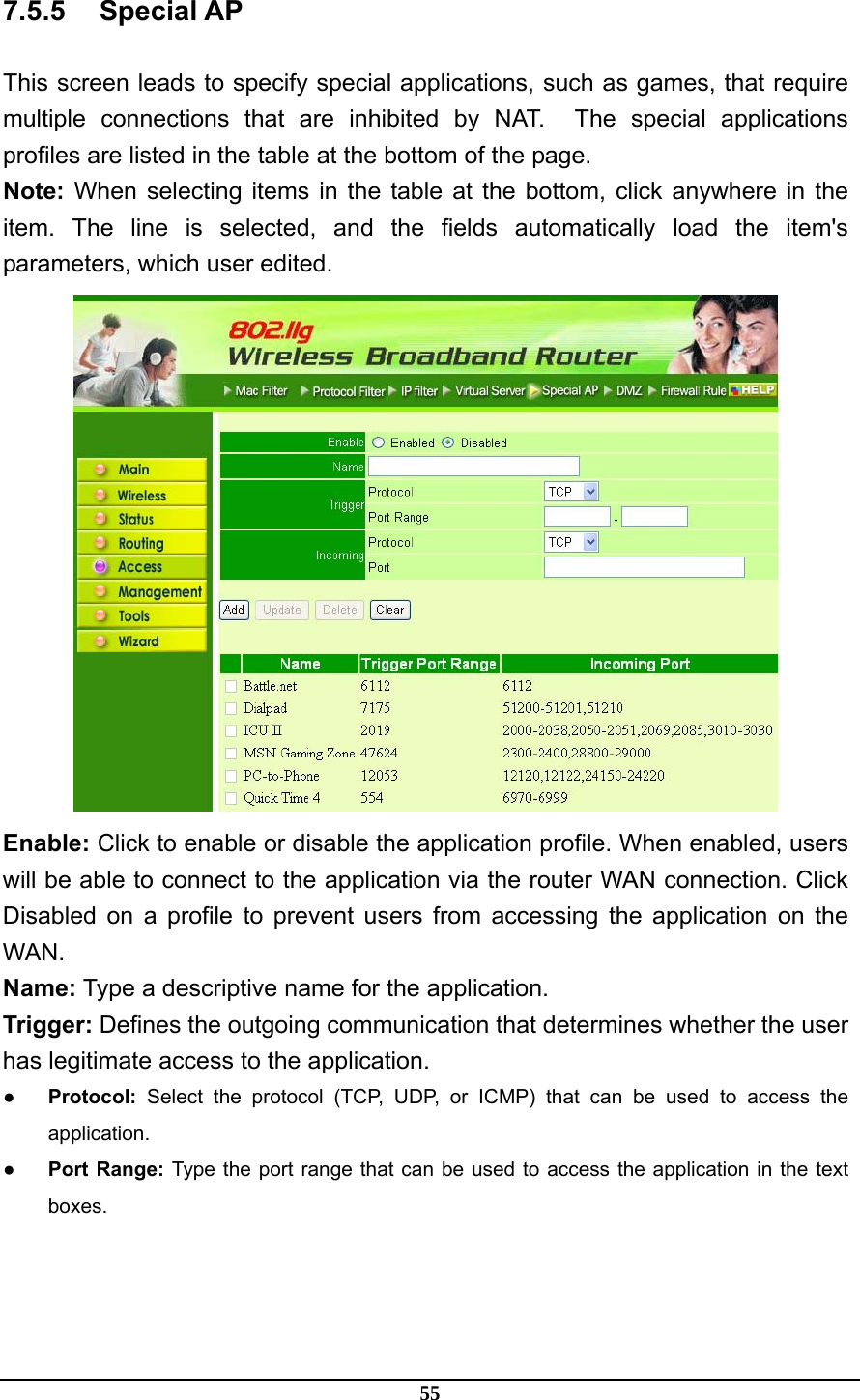
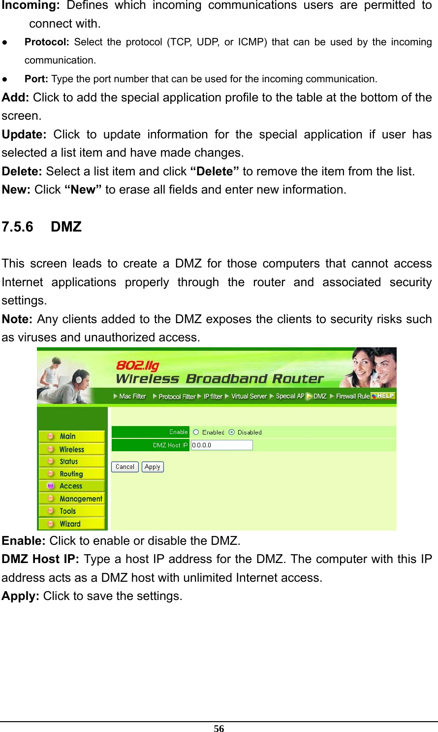
Manual Part2
Manual Part2
Navigation menu
Upload a User Manual
Namespaces
Wiki Guide
HTML
PDF
Info
Views
User Manual
Discussion / Help
Navigation