Canon Production Printing Netherlands 3010105668 rfid module User Manual rfid hardware REV4
Oce Display Graphics Inc rfid module rfid hardware REV4
UserManual.wiki
>
Canon Production Printing Netherlands
>
3010105668 User Manual
USERS MANUAL
Navigation menu
Upload a User Manual
Namespaces
Wiki Guide
HTML
PDF
Info
Views
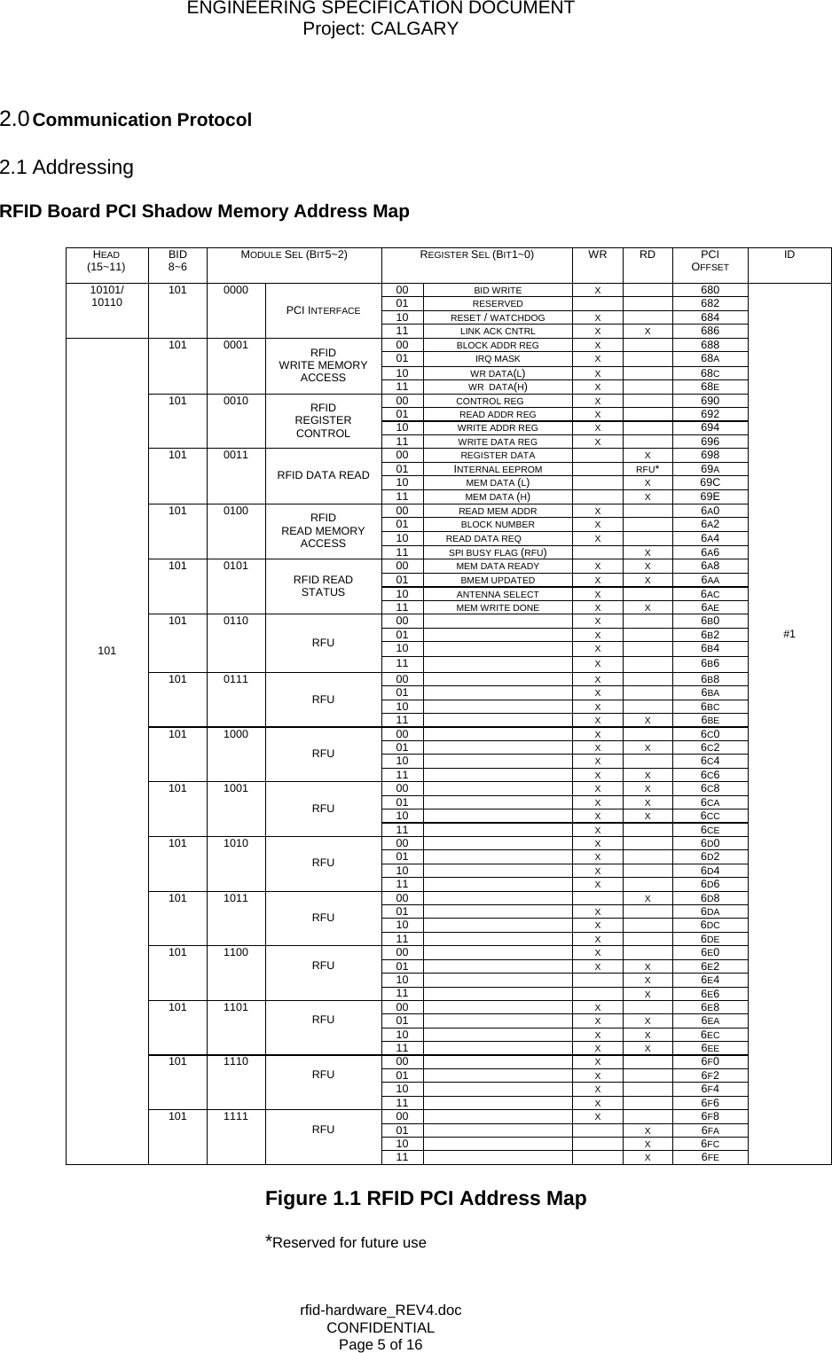
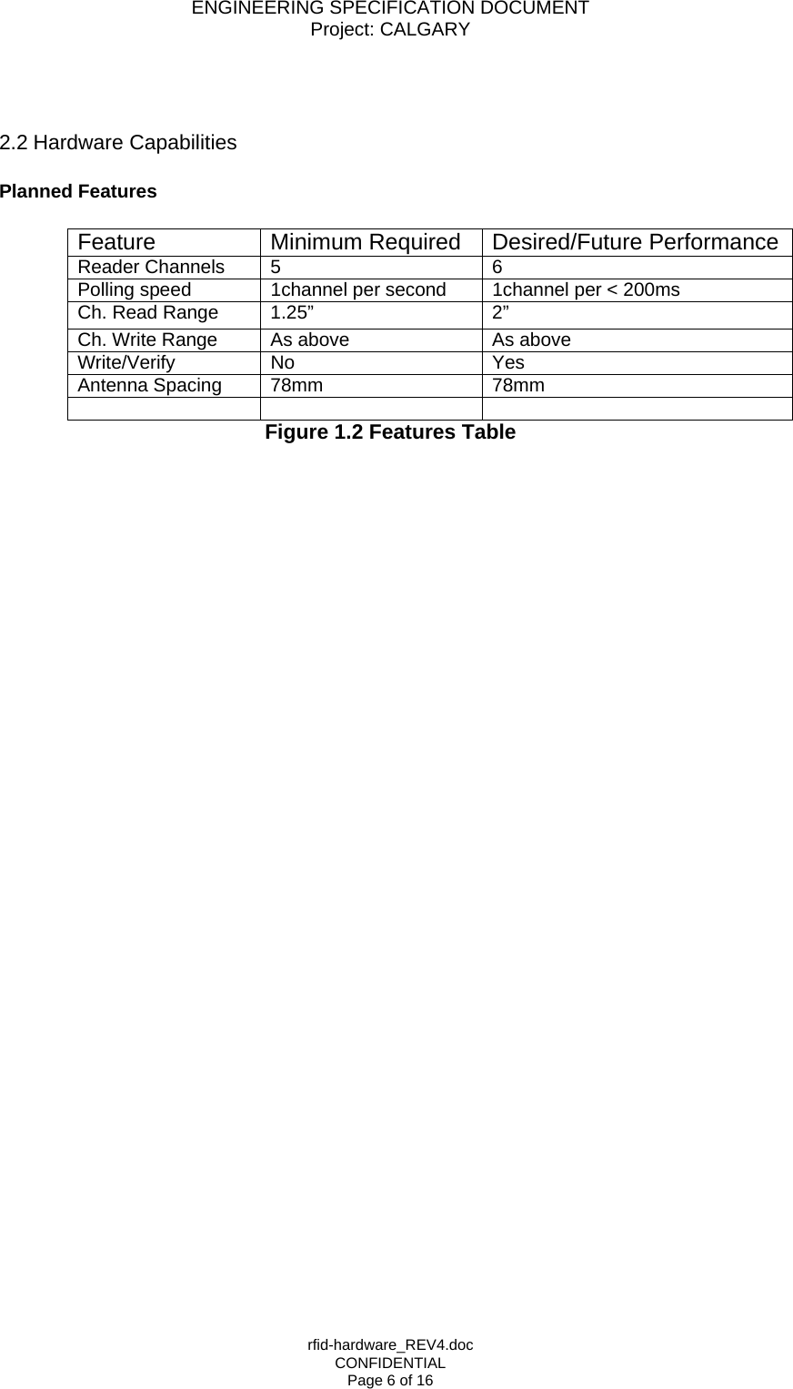
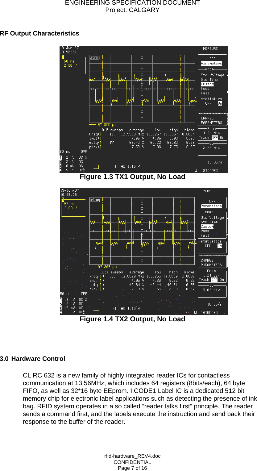
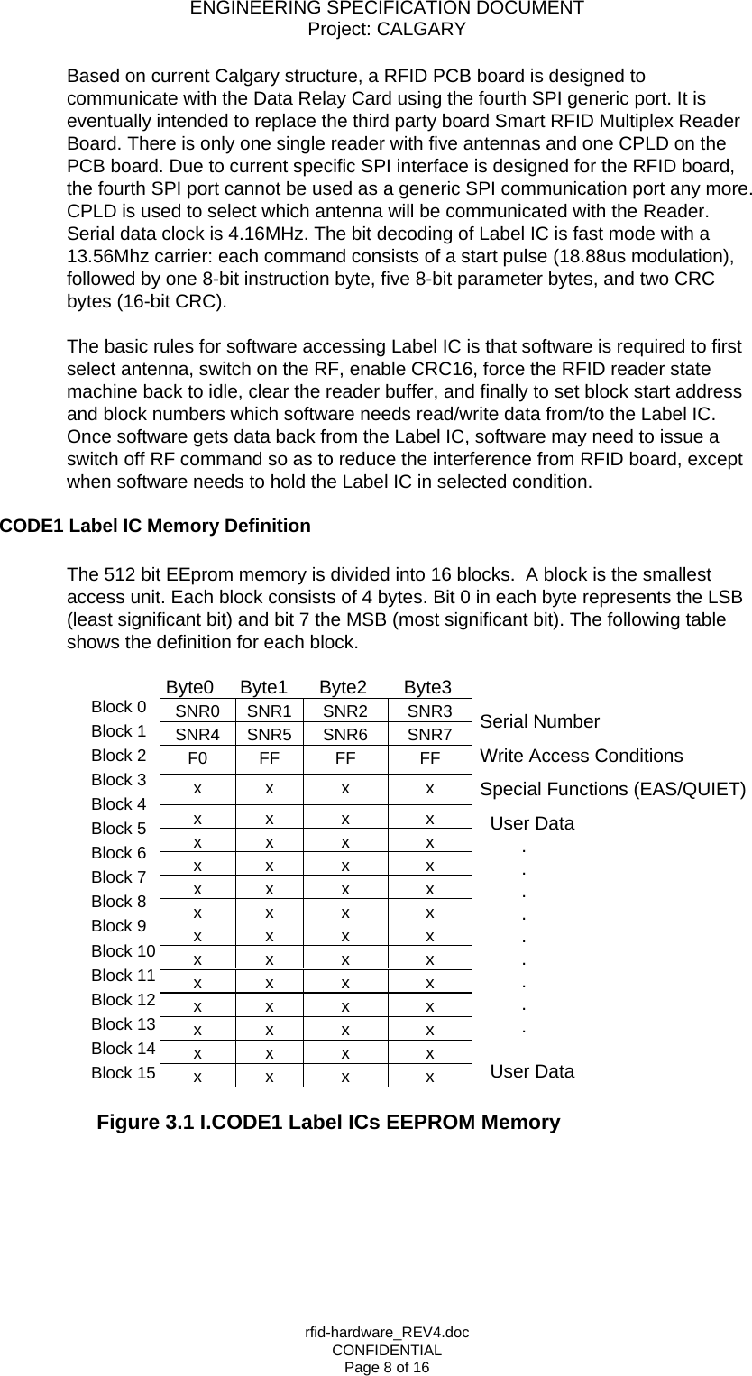
User Manual
Discussion / Help
Navigation