Canon FM48944 Wireless LAN Module User Manual Instllation manual
Canon Inc Wireless LAN Module Instllation manual
Canon >
Contents
- 1. Instllation manual
- 2. User manual for host
Instllation manual
1-1
1-1
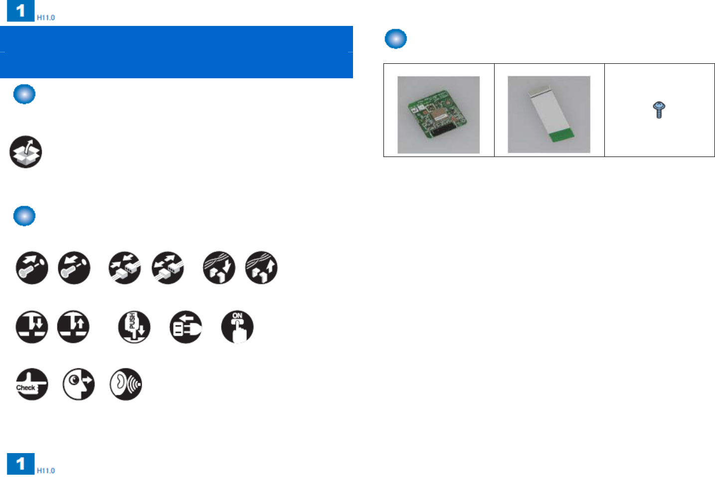
Wireless LAN Board-C1 Check of bundled parts
Installation procedure
[1] Wireless board x 1 [2] Flat cable x 1 [3] Screw (TP;M3x6) 1
If bundled parts are used;
If the parts bundled with this product are used, the symbol indicating the use of
bundled parts is illustrated.
Bundled
parts
In this procedure manual, the frequent operations are illustrated with symbols.
Screw Connector Binding wire
Attach Detach Attach Detach Attach Detach
Claw
Attach Detach Push Plug in Switch ON
Check Visual check Noise check
1-2
1-2
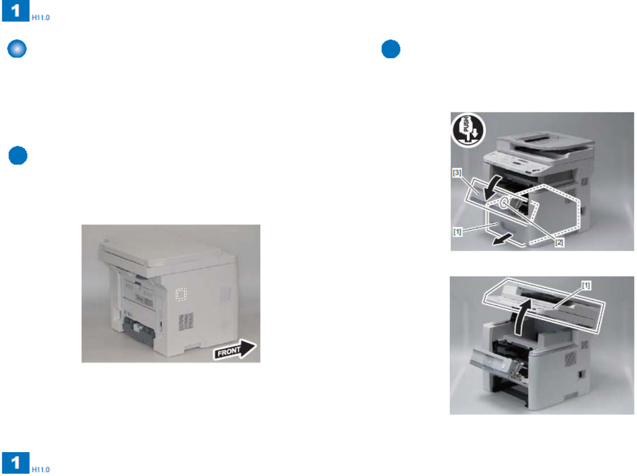
Check of main power OFF Installation procedure
Check that the main power switch of the main body is OFF.
1) Turn OFF the main power switch of the main body.
2) Check that the indication lamps on the operation panel and the main power
lamp are out, and pull out the power plug.
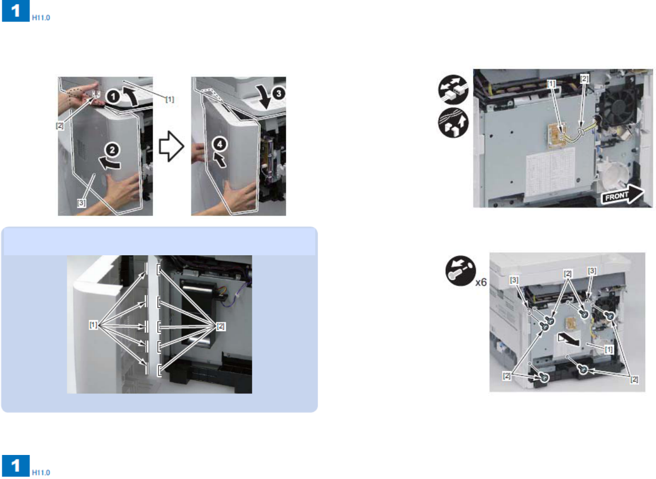
1) Press cassette [1].
2) Press button [2]. Open cartridge door unit [3].
3) Open ADF unit and reader unit [1].
Schematic diagram of attachment
1-3
1-3
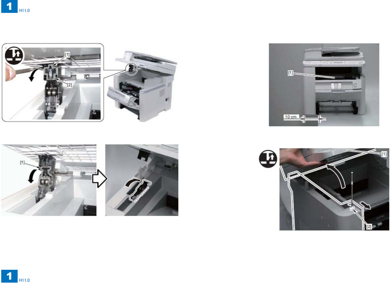
4) Remove claw [1] and arm cover [2].
5) Disconnect arm [1] and push it back.
6) Shift the left side of main body [1] from the workbench by about 10 cm.
7) Open ADF unit and reader unit [1]. Reset claw [2].
1-4
1-4
8) Open ADF unit and reader unit [1]. While applying stress to left cover [2] in
the arrow direction, reset claw [3].
9) Reset two bottom claws [2] with left cover [1] opened in the arrow
direction.
10) Open ADF unit and reader unit [1]. Reset claw [3].
Memo
Remove the claw with right cover edge [2] reset from four rear cover hooks [1]. Memo
Reset claw [3] while holding left cover [2].
1-5
1-5
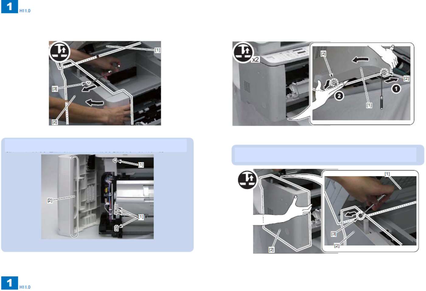
11) Open ADF unit and reader unit [1]. Remove boss [2] from left cover [3].
12) Remove left cover [3].
13) After removing the left cover, put the main body at the center of the
workbench.
14) Remove connector [1] from the counter board.
Wire saddle [2]
15) Remove controller cover [1].
Six screws [2] (Removed screws are used in step 19).)
Hook [3]
Memo
For attachment, attach left cover [1] aligning with four protrusions [2] on the left
bottom cover.
1-6
1-6
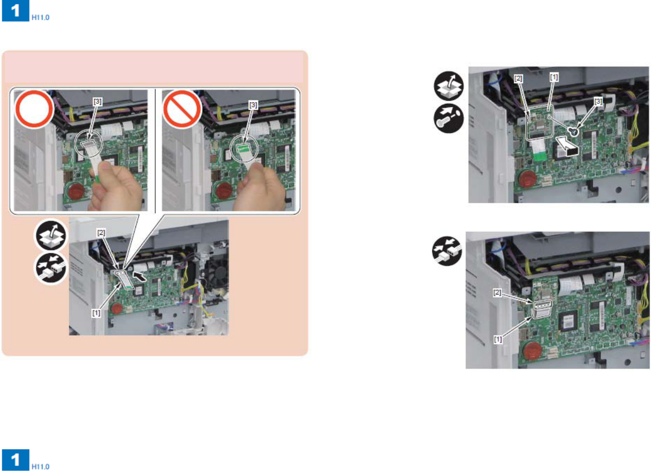
16) Attach Flat cable [1] on the main controller board [2].
17) Attach Wireless board [1].
・Hook [2]
・Screw [3] (TP;M3×6)
18) Attach Flat cable [1] on the W-LAN board [2].
19) Put all covers back.
・Control cover
・Left cover
CAUTION:
・Insert the Flat Cable face up.
1-7
1-7
Note
■Put following sentences outside of the host device if the FCC ID on the module cannot be seen from exterior.
・“Contains Transmitter Module FCC ID: AZDFM48944” or “Contains FCC ID: AZDFM48944”
・“Contains Transmitter Module IC: 498D-FM48944” or “Contains IC: 498D-FM48944”
■User’s manual of the host device should contain sentences listed below.
This device complies with Part 15 of FCC Rules and RSS-Gen of IC Rules. Operation is subject to the following two conditions: (1) this device may not cause
interference, and (2) this device must accept any interference, including interference that may cause undesired operation of this device.
This equipment complies with FCC/IC radiation exposure limits set forth for an uncontrolled environment and meets the FCC radio frequency (RF) Exposure
Guidelines in Supplement C to OET65 and RSS-102 of the IC radio frequency (RF) Exposure rules. This equipment should be installed and operated keeping the
radiator at least 20cm or more away from person’s body (excluding extremities: hands, wrists, feet and ankles).
FCC WARNING
Changes or modifications not expressly approved by the party responsible for compliance could void the user’s authority to operate the equipment.
This transmitter must not be co-located or operated in conjunction with any other antenna or transmitter.
This equipment has been tested and found to comply with the limits for a Class B digital device, pursuant to part 15 of the FCC Rules. These limits are designed to
provide reasonable protection against harmful interference in a residential installation. This equipment generates, uses and can radiate radio frequency energy and,
if not installed and used in accordance with the instructions, may cause harmful interference to radio communications. However, there is no guarantee that
interference will not occur in a particular installation. If this equipment does cause harmful interference to radio or television reception, which can be determined by
turning the equipment off and on, the user is encouraged to try to correct the interference by one or more of the following measures:
—Reorient or relocate the receiving antenna.
—Increase the separation between the equipment and receiver.
—Connect the equipment into an outlet on a circuit different from that to which the receiver is connected.
—Consult the dealer or an experienced radio/TV technician for help.
This equipment complies with the Canadian ICES-003 Class B limits.