Cansec Systems ZODRCS ZORDCS User Manual T MyFiles Wiring Zodiac Wiring
Cansec Systems Ltd ZORDCS T MyFiles Wiring Zodiac Wiring
Contents
- 1. users manual 1
- 2. users manual 2
users manual 2

CANSEC SYSTEMS LTD., 3105 Unity Drive, Unit 9, Mississauga, Ontario, L5L 4L2 Tel: (905) 820-2404 Fax: (905) 820-0301
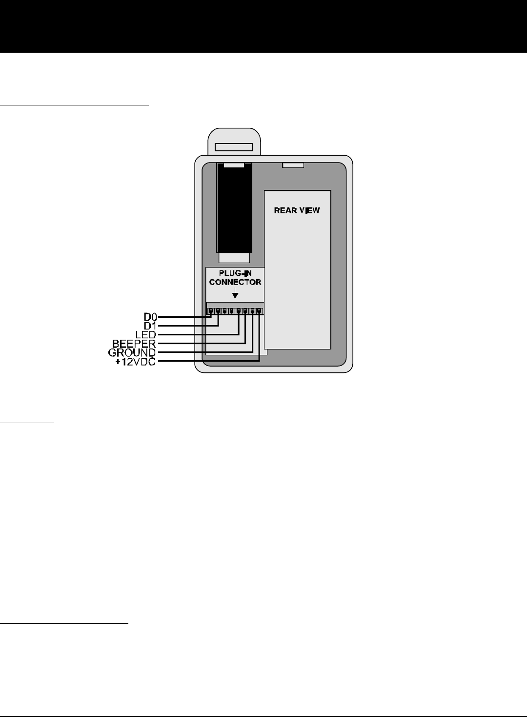
WIRING TO HOST CONTROLLER:
MOUNTING:
Zodiac mounts on a single-gang electrical box.
1. Remove screw from bottom of unit.
2. Remove back mounting plate by pulling gently from inside the cable feed-through hole.
3. Insert the Wiegand cable from the wall through the hole in the back plate, then mount the back plate to the electrical
box with the supplied screws.
4. Remove the plug-in connector from the unit and connect Wiegand cable as per wiring instructions on Page 1. Plug the
connector back into the unit.
Important: Confirm wiring as 12VDC applied to incorrect pin can damage the unit.
5. Attach the main unit to the back plate by tilting the bottom of the unit toward you, then sliding the top of the unit over
the back plate.
6. Secure the main unit to the back plate with the screw removed in step 1.
LED and BEEPER CONTROL:
The LED line is used to control the LED on the right side of the unit. This LED is normally RED and will turn GREEN when
the line is pulled LOW.
The BEEPER line is used to activate the unit’s internal beeper. The beeper will sound if the line is pulled LOW.
INSTALLATION INSTRUCTIONS:
MODEL CA-ZODRCS ZODIAC FINGERPRINT ACCESS READER

CANSEC SYSTEMS LTD., 3105 Unity Drive, Unit 9, Mississauga, Ontario, L5L 4L2 Tel: (905) 820-2404 Fax: (905) 820-0301
SPECIFICATIONS:
Reader Output:
26 or Cansec Proprietary Wiegand
Operating Temperature:
-40 to +70 C
Indoor (Outdoor with Heated Enclosure)
Size:
3 1/4" (w) x 4 3/4" (h) x 1 1/2" (d)
Weight:
10 oz
Housing:
High Impact Polycarbonate (Lexan)
Mounting:
Single gang electrical box
Sensor:
Manufacturer: SecuGen®
Type: Optical
Verification: <1 Second (after template is read)
Supply Voltage:
12VDC, 400 mA
LED Indicators:
Bi-Color Standard (red, green)
1 x Authentication Indicator
1 x Externally Controlled Indicator
Audio Tone:
Standard
Cable:
22 AWG, 6 Conductor, Stranded,
Overall Shield,
Maximum 500 ft. to controller
NOTE: This equipment has been tested and found to comply with the limits for a Class B digital devices, pursuant to Part 15 of the FCC Rules. These
limits are designed to provide reasonable protection against harmful interference in a residential installation. This equipment generates, uses, and can
radiate radio frequency energy and, if not installed and used in accordance with the instruction manual, may cause harmful interference to radio
communications. However, there is no guarantee that interference will not occur in a particular installation. If this equipment does cause harmful
interference to radio or television reception, which can be determined by turning the equipment off and on, the user is encouraged to try to correct the
interference by one of more of the following measures:
•Reorient or relocate the receiving antenna
•Increase the separation between the equipment and receiver
•Connect the equipment into an outlet on a circuit different from that to which the receiver is connected.
•Consult the dealer or an experienced radio/TV technician for help.
Warning: Changes or modifications not expressly approved by Cansec Systems Ltd. could void the user's authority to operate the equipment.