Capital Prospect AM001 Home Smart Centre User Manual Users Guide
Capital Prospect Ltd Home Smart Centre Users Guide
UserManual.wiki
>
Capital Prospect
>
AM001 User Manual
User Manual
Navigation menu
Upload a User Manual
Namespaces
Wiki Guide
HTML
PDF
Info
Views
User Manual
Discussion / Help
Navigation

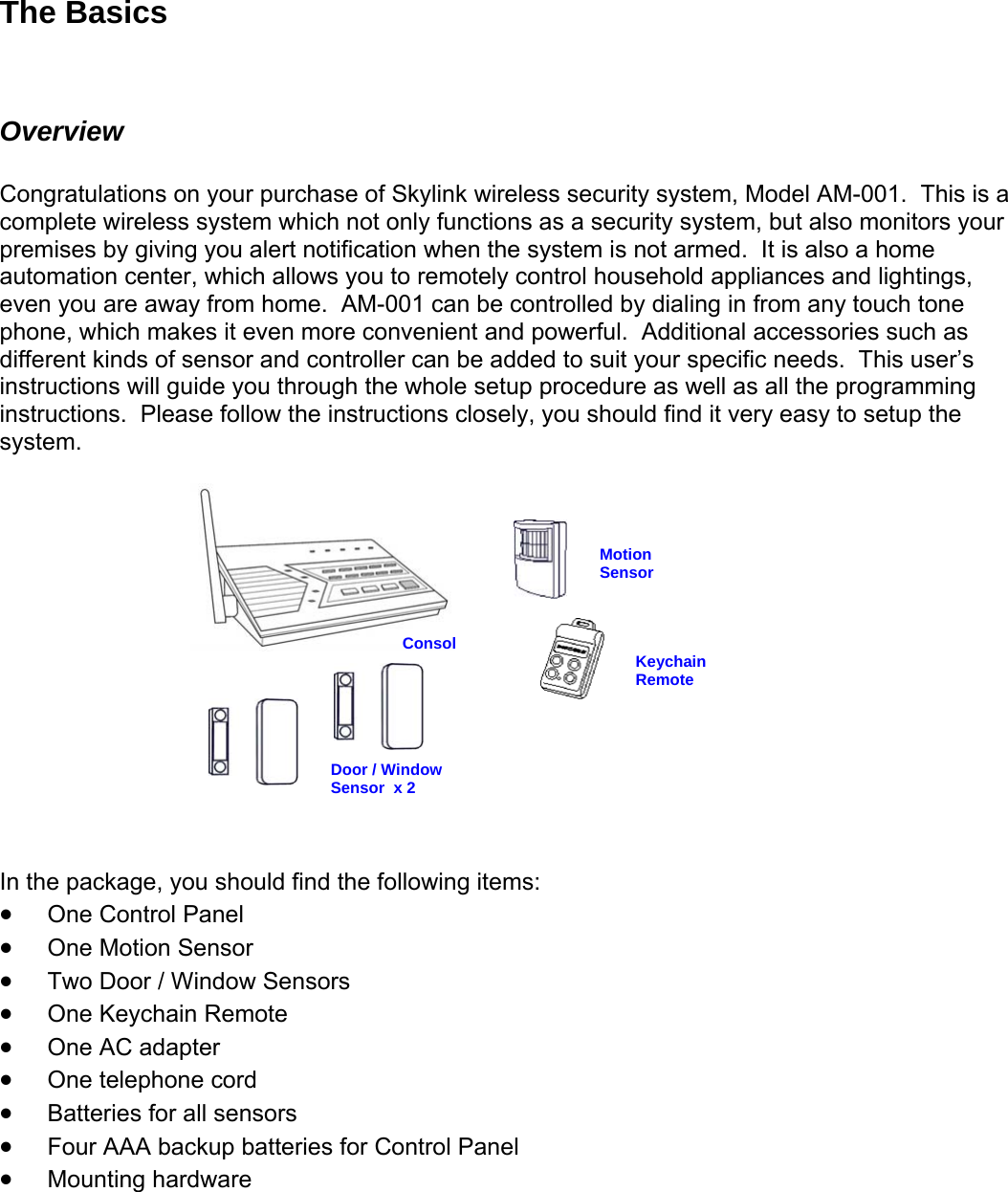
![Program Passwords Master Password can be used for programming, arming, disarming the system, and telephone access. The default Master Password is [1234]. Secondary Password can be used for arming, disarming the system, and telephone access. Secondary Password cannot be used for programming. The default Secondary Password is [0000]. Duress Password is used when you are forcibly compelled to disarm the control panel. You may enter the Duress Password. Entering the duress password will stop the siren from sounding but the control panel will silently call the emergency phone numbers for help. The default Duress Password is [3838]. You should definitely change this password and let all the users know this password. In order to change the password, follow the procedures below. 1. Press the PROG button on the side of the control panel, the [PROG] LED will be on.. 2. Enter the current Master Password, [1234]. Enter [2], which represents Password Programming. 3. Select the type of password you would like to change: • Enter [1] for Master Password, • Enter [2] for Secondary Password • assword Enter [3] for Duress P4. Enter new 4-digit password. 5. Enter new 4-digit password again, password accepted. Program Emergency Phone Numbers You can program up to 5 Emergency Phone Numbers. When the system is in panic situation, he control panel will call 5 phone numbers and announce its status t ide of the control panel, the [PROG] LED will be on. 1. Press the PROG button on the right s2. Enter the current Master Password. 3. Enter [1], which represents Phone Number Programming. 4. Select the phone memory from 1 to 5. Note: In an emergency, the control panel will call phone memory 1 as the first number, then phone memory 2 will be called, then memory 3, 4, and 5. So it is recommended to program most important phone number in phone memory 1. [Do not program police, 911 or fire station phone numbers into the control panel.] 5. Enter the phone number then press [Arm]. Note: You may enter a 3-second pause by pressing [Mute] if needed. The phone number can be up to 29-digit long, including multiple pause periods. 6. After entering the phone number, enter how many times you want the phone number to be called, from 1 to 9 times. Press ARM to confirm. 7. After entering the redial, enter how many times you want the emergency message to be played, from 1 to 9 times. It is recommended to play the message at least 2 times. Press ARM, phone accepted. WHEN PROGRAMMING EMERGENCY NUMBERS AND (OR) MAKING TEST CALLS TO EMERGENCY NUMBERS:](https://usermanual.wiki/Capital-Prospect/AM001/User-Guide-572885-Page-7.png)


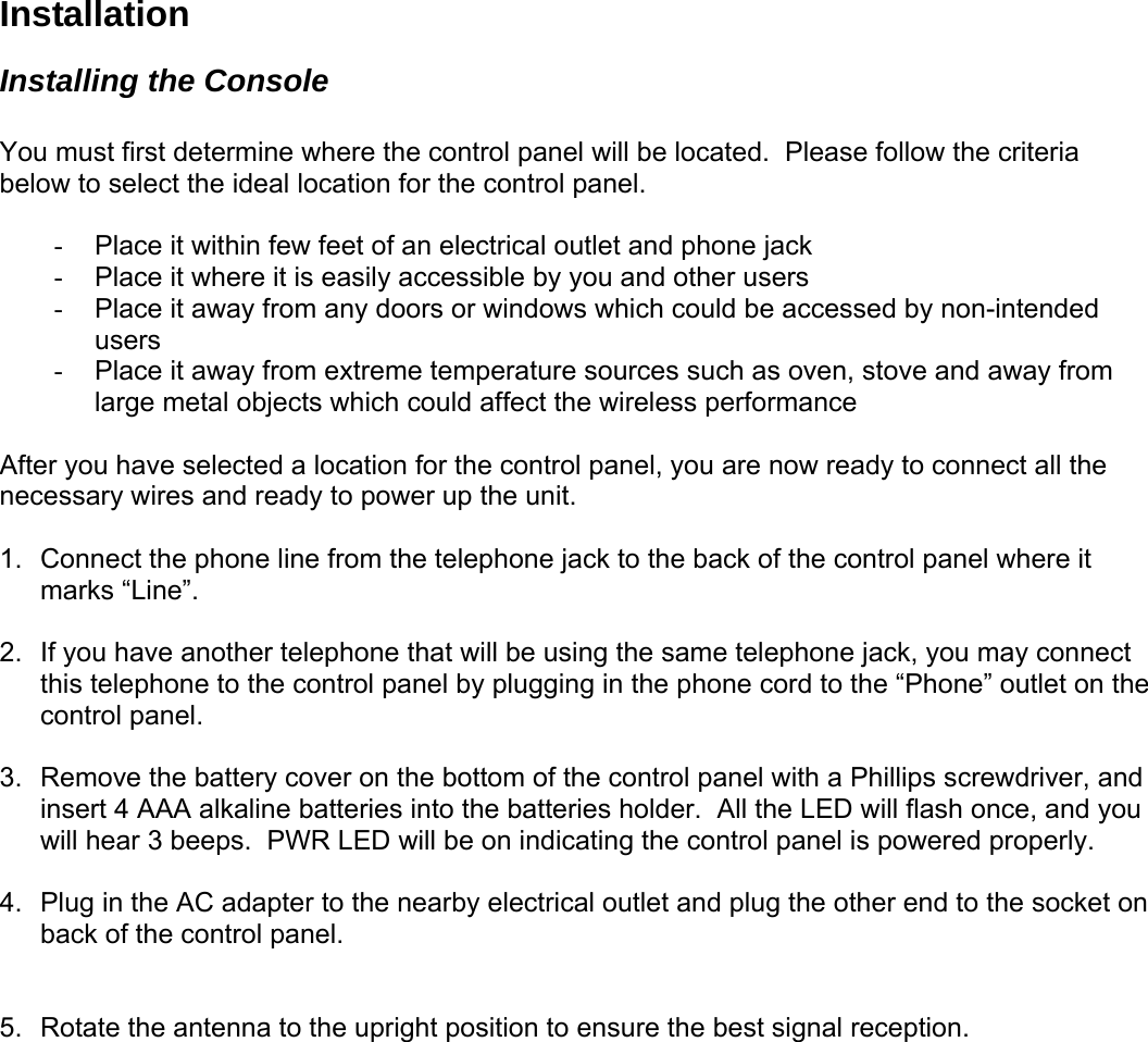
![To access the control panel away from home 1. Call your home phone number, or the number that the control panel is connected to. Hang u2. p after hearing the second ring. 4. need to enter hear “Password Accepted”, otherwise, you will hear “Password Failure”. ou can have access to all the operations listed below: able 1: Remote Phone Operations rgency phone umbers, the called party will hear the emergency message, it will then ask for a password. If a valid password is entered, the operations listed in Table 1 will be available. ds, including ow the program additional sensors, remotes, how the buzzer behaves for different zones, The follow advanced programming fields. Options Com3. Wait at least 10 seconds, but not more than 1 minute, then call your home phone numberagain. The control panel will pick up the phone call and ask for a password. You either the Master Password or Secondary Password. If the password is correct, you will 5. Once the password is accepted, y T System Operation Phone Command Description Turn on device X X + [#] on, will hear Turn lights confirmation, “Device OnAccepted” Turn off device X X + [*] Turn lights off, will hear f confirmation, “Device OfAccepted” Check system status [8] + [#] Will hear system status announcement Arm [7] + [#] Will hear “System Armed” Disarm [9] + [#] Will hear “System Disar med” The same operations can be performed when the control panel calls the emeDisconnect [0] + [#] Phone line disconnect n Advanced Programming You can customized the control panel in different configurations to suit your neehevent trigger setting etc. ings are the Programming mand Learn Sensor [PROG] + [3] Learn Remote or Receiver [PROG] + [4] Beep / Alarm [PROG] + [5] Auto Mute [PROG] + [6] Event Trigger [PROG] + [7]](https://usermanual.wiki/Capital-Prospect/AM001/User-Guide-572885-Page-17.png)
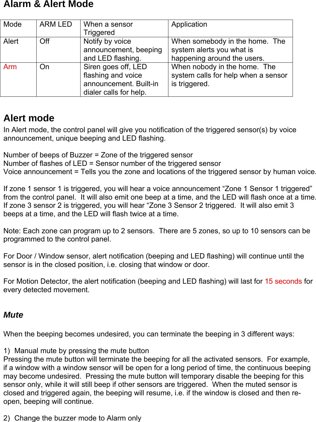
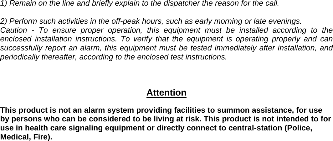
![Alert Zone [PROG] + [8] Erase Sensor [PROG] + [9] Erase Remote / Receiver [PROG] + [0] Learn Sensor t trigger, xplanation for each zone dependent feature can be found in Advanced rogramming. ensor Location Selection Guide bled. It is not possible to enable a zone dependent feature for sensor 1 only, but ne 2. 3. able es. Detailed explanation for each feature can be found in Advanced Programming. en You can program up to 10 sensors to the control panel. There are 5 zones, each zone can program 2 sensors. Before programming a sensor, you must decide which sensor location(zone number and sensor number) you would like to program the sensor to. It is strongly recommended that you refer to “Sensor Location Selection Guide” and study the 4 zone dependent features before deciding which sensor location you would like to program the new sensors to. The 4 zone dependent features are: 1) buzzer sound, 2) auto mute, 3) even) alert zone. E4P S You can program up to 10 sensors to the control panel. There are 5 zones and there are some zone dependent features. Zone dependent feature means all the sensors in that zone will operate based on the setting for that zone. So if you program 2 sensors into one zone, those 2 sensors will react in the same manner for those zone dependent features. For example, if you enable the Auto-Mute feature for zone 1, both zone 1 sensor 1, and zone 1 sensor 2 will have his feature enatnot sensor 2. Therefore, the followings are some suggestions of how you should select the sensor location. 1. Check all the zone dependent features, and determine if you would like to enable any oof them. If you decide not to enable any zone dependent features and keep the factory default setting, you can simply program the sensor to any sensor location based on your own preference. Omit the following steps. If you decide to enable some of the zone dependent features, check Table 2 below. Circlethe zone dependent feature selections. If there are features that you would like to enfor more than 2 sensors, you need to select more than one zone for those featur Sensor 1 Sensor 2 Zone Depend t Features Location Location Auto Mute Beep / Alarm Event Trigger Alert Zone 1 Beep / Alarm Y / N Disabled / On / Off Y / N Zone 2 Beep / Alarm Y / N Disabled / On / Off Y / N Zone 3 Beep / Alarm Y / N Disabled / On / Off Y / N Zone 4 Beep / Alarm Y / N Disabled / On / Off Y / N Zone 5 Beep / Alarm Y / N Disabled / On / Off Y / N](https://usermanual.wiki/Capital-Prospect/AM001/User-Guide-572885-Page-18.png)
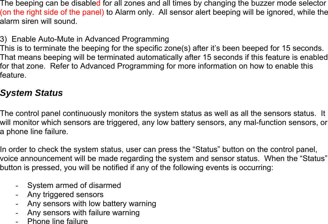
![4. Once you have filled out the table, it should look something like this. enSensor 1 Sensor 2 Zone Depend t Features Auto Mute Location Beep / Alarm Event Trigger Alert Location Zone 1 Front Door Front Window Beep / Alarm Y / N Disabled / On / Off Y / N Zone 2 Kitchen Motion Beep / Alarm Y / N Disabled / On / Off Y / N Zone 3 Back Door Y / N Beep / Alarm Disabled / On / Off Y / N Zone 4 Backyard Motion Beep / Alarm Y / N Disabled / On / Off Y / N Zone 5 Basement Water Motion Beep / Alarm Y / N Disabled / On / Off Y / N Basement You can now refer to each column representing the zone dependent features, to program each zone with the selected feature. For example, Auto Mute feature is only enabled for zone 3, when you are in the auto mute programming, you should set it so that auto mute is only enabled for zone 3, the rest of the zone should hav5. e this feature disabled. Repeat this step for all 4 zone dependent features programming. earn Sensor – continue r to e control panel. To learn a sensor into the control panel, follow the instructions below. 6. sword is e emitted and [PROG] LED will be off. 8. once, some of or. 9. 1 for ee Fig. X. After selecting the zone and sensor numbers, that zone LED will be on. L After studying the “Sensor Location Selection Guide”, you may proceed to learn the sensoth 5. Press the [PROG] button on the side of the control panel, the [PROG] LED will be on. Enter the current Master Password. Control panel will emit 3 beeps if the valid pasentered, otherwise a single long beep will b7. Enter [3], which represents “learn sensor”. Notice all 5 zone LEDs, some of them may be off, some of them may flashthe may flash twice. The LED flashing represents the occupied sensors. • If the zone LED remains off, that indicates that zone is not occupied by any sens• If the zone LED flashes once, that indicates sensor 1 of that zone is occupied. • If the zone LED flashes twice, that indicates sensor 2 of that zone is occupied. You may now select a zone and sensor location to program the sensor to. Select the zoneand sensor number by pressing on to button 1 to 0. Buttons 1 to 5 represent sensorzones 1 to 5. Buttons 6 to 0 represent sensor 2 for zones 1 to 5. S Sensor 1 Sensor 2 Zone 1 Button [1] Button [6] Zone 2 Button [2] Button [7] Zone 3 Button [3] Button [8] Zone 4 Button [4] Button [9] Zone 5 Button [5] Button [0]](https://usermanual.wiki/Capital-Prospect/AM001/User-Guide-572885-Page-19.png)
![10. Activate the sensor, the control panel will beep and you will hear “Zone _ Sensor _ Accepted” if the sensor is programmed, the [PROG] LED will be off. To program another sensor, repeat the above steps. ote: If an occupied sensor location is selected, the new sensor will replace the old one. dditional keychain or keypad remote can be programmed to the control. You may also odel SW-100R or Garage e programmed the control panel. Receivers should be programmed to Device 1 to Device 5. ll1. 2. panel will emit 3 beeps if the valid password is ente , 3. Enter [4] arn Keychain / Receiver”. Notice all 5 zone LEDs, some of them aflashing N Learn Remote / Receiver Aprogram additional receivers such as the Light Switch Receiver, MDoor Receiver GD-101R. Maximum of 5 keychain remotes and 5 receivers can bto •• Keychain or keypad remote should be programmed to Device 6 to Device 0. ow the instructions below to program remotes / receivers. Fo Press the [PROG] button on the side of the control panel, the [PROG] LED will be on. Enter the current Master Password. Controlred otherwise a single long beep will be emitted and [PROG] LED will be off. , which represents “Le m y be off, some of them may flash once, some of the may flash twice. The LED represents the occupied sensors. • If the zone LED remains off, that indicates that zone is not occupied by any keychain / receiver. • If the zone LED flashes once, that indicates a receiver has occupied that device. Zone 1 LED flashes once means Device 1 is occupied. • If the zone LED flashes twice, that indicates a keychain / keypad remote has occupied that zone. Zone 1 LED flashes twice means Device 6 is occupied. For programming a receiver, select a device number from Device 1 to Device 5. Press and 4. ce on 5. selected, that zone LED will be on steadily. You can now transmit a signal by pressing one of the buttons from the keychain. . The control panel will beep and you will hear “Device X Accepted” if the device is programmed and the [PROG] LED will be off. To program another remote / receiver, repeat hold the learn button on the receiver continuously, you will see the LED flashing rapidly. To select device 1, press button 6. The LED stop flashing indicate the receiver has received the signal. Then press button 1 on control panel for device 1. Once a device is selected, that zone LED will be on steadily. . You can now transmit a signal by pressing onlearn button on the receiver. For programming a keychain, select a device number from Device 6 to Device 0. To select device 6, press button 6. Once a device is 6the above steps. Note: If an occupied device is selected, the new sensor will replace the old one.](https://usermanual.wiki/Capital-Prospect/AM001/User-Guide-572885-Page-20.png)
![Zone Dependent Setting – Beep / Alarm r can customize the audio warning so that when a sensor is triggered, it may bee sesecu • alarm immediately, but it will stop when the sensor is back to normal (door closes). It umbers since it is not armed. without entry delay, it is called tered. l z the factory. • • or is not located outdoor 1. Pre th2. Enter the current Master Password. Control panel will emit 3 beeps if the valid password is 3. ents the current beep / alarm setting. • If the zone LED flashes, that ind the zon rammed to “Beep”. • If the zone LED remains steadily on, that indicates the zone is programmed to “Alarm”. 4. To change the setting between beep and alarm, press buttons 1 to 5 will set that zone to beep. Pressing buttons 6 to 0 will set that zone to alarm. Refer to Fig X. After making the change, notice the stat zone es a Beep Alarm Up, or an alarm may sound immediately. Depending on whether the control panel is in alert mode or rity mode, the audio warning will be different. Alert mode: If a sensor is triggered (i.e. opening a door) with the alarm feature on, thewill soundcontrol panel will not call the emergency phone n Security mode: If a sensor is triggered (i.e. opening a door) with the alarm feature on and •the system is armed, the siren will sound immediately “Instant Alarm”. The siren will not stop until the siren timeout or a valid password is enControl panel will call the emergency phone numbers to notify the users of the alarm situation. l ones were programmed to beep at A It is recommended to program a zone into Alarm mode if: • You need immediate attention if that sensor is triggered, such as flood sensor, smoke sensor etc. The sensor will not be triggered on a daily basis The sensss e [PROG] button on the side of the control panel, the [PROG] LED will be on. entered, otherwise a single long beep will be emitted and [PROG] LED will be off. Enter [5], which represents “Beep / Alarm” setting. Notice all 5 zone LEDs, some of them may be off, some of them may flash. The LED flashing repres icates e is progus of the LED chang s well. Zone 1 Button [1] Button [6] Zone 2 Button [2] Button [7] Zone 3 Button [3] Button [8] Zone 4 Button [4] Button [9] Zone 5 Button [5] Button [0] 5. You are allow to make unlimited changes before programming is quit. Once you are satisfied with the settings, press [PROG] to quit programming and the settings will be saved.](https://usermanual.wiki/Capital-Prospect/AM001/User-Guide-572885-Page-21.png)
![Zone Dependent Setting – Auto Mute Once a sensor is triggered, audio warning will be emitted, either beep or alarm. For example, if n for This fea re 1. current Master Password. Control panel will emit 3 beeps if the valid password is entered, otherwise a single long beep will be emitted and [PROG] LED will be off. 3. Enter [6], which represents “A ti ome of them may be off, some of them may flash. The LED flashing represents the current auto mute setting. • If the zone LED flashes, that indicates auto mute is disabled • If the z remains s4. To change the setting between au ble and disa buttons 1 to 5 will disable auto mute for those zones buttons 6 to le auto mute for those zones. Refer to Fig X. After maki notice the status of the zone LED changes as well. a door is opened, the audio warning will not stop until the door is closed. If the door is ope2 hours, the audio warning will go on for 2 hours. There are times that this is not desired. With the auto mute feature enabled, the audio warning will go on for only 15 seconds. After that, if sensor remains open, only the zone LED will flash to indicate the sensor is triggerethe d. Audio warning will go on again if the sensor is closed and open again. tu was disabled for all zones at the factory. To enable auto mute feature, follow the instructions below. Press the [PROG] button on the side of the control panel, the [PROG] LED will be on. Enter the 2. uto Mute” setting. No ce all 5 zone LEDs, sone LED teadily on, that indicates auto mute is enabled to mute ena ble, press . Pressing 0 will enabng the change, Disable Auto Mute Enable Auto Mute Zone 1 Button [1] Button [6] Zone 2 Button [2] Button [7] Zone 3 Button [3] Button [8] Zone 4 Button [4] Button [9] Zone 5 Button [5] Button [0] 5. You are allowed to make unlimited changes before programming is quit. Once you are satisfied with the settings, press [PROG] to quit programming and the settings will be saved. ically. It is called Event Trigger. nel will transmit a signal to activate the en the door sensor is open, turn the s Even , you can program device 1 to be on or off when zone 1 sensor(s) is triggered. You can also program device 2 to be on / off when zone 2 sensor(s) is triggered. Zone Dependent Setting – Event Trigger Home Automation is one of the features that makes this system so powerful. You can control p to 5 different devices not only manually, but also automatuThat means when a sensor is triggered, the control paesignated receiver. Applications include: d• Lights on when you open the front door (whlighting receiver on) • Lights on when you walk into the kitchen (when the motion sensor in the kitchen iactivated, turn the lighting receiver on) t trigger is only applicable to the sensors and receiver in the same zone. For example](https://usermanual.wiki/Capital-Prospect/AM001/User-Guide-572885-Page-22.png)
![feature was disabled for all zones at the factory. This To en le 1. Press e [PROG] LED will be on. 2. is en D will be off. ab event trigger, follow the instructions below. the [PROG] button on the side of the control panel, thEnter the current Master Password. Control panel will emit 3 beeps if the valid password tered, otherwise a single long beep will be emitted and [PROG] LE3. Enter [7], which represents “Event Trigger” setting. Notice all 5 zone LEDs, some of them may be off, some of them may flash once, some of them may be on steadily. The LED flashing represents the current event trigger setting. • If the zone LED is off, that indicates event trigger is disabled. • If the zone LED flashes, that indicates event trigger is enabled, and it will turn off the corresponding device when the sensor(s) is activated • If the zone LED remains steadily on, that indicates event trigger is enabled, and turn it will on the corresponding device when the sensor(s) is activated . To change the event trigger setting, press buttons 1 to 5 will dzones. P ssing buttons 6 event trigger for those zones. However, even this feature is enabled, you still have to select whether you want to turn that device on or off when the sensor(s) is trig ssing buttons [6] to [0] will toggle the setting between on and off. For exa LED is currently vent trigger for zone 2 is enable with the Off signal, you can press button [7] to change it to the On signal. Pressing [7] again will change it back to Off signal. Refer to Fig X. After making the change, notice the status of the zone LED changes as w Disable Event Trigger Enable Event Trigger (Toggle between Off 4isable event trigger for those re to 0 will enablegered. Premple, if the showing eell. and On) Zone 1 Button [1] Button [6] Zone 2 Button [2] Button [7] Zone 3 Button [3] Button [8] Zone 4 Button [4] Button [9] Zone 5 Button [5] Button [0] 5. You are allowed to make unlimited changes before programming is quit. Once you are satisfied with the settings, press [PROG] to quit programming and the settings will be ote: If event triggered is enabled for a door sensor, which turn lights on when it is open, this ave n operate in 2 different modes, 1) Alert Mode, 2) nd immediately (with instant not want to trigger the alarm when the system saved. Nfeature will not be activated during exit delay. Since during exit delay, users suppose to lethe premises and therefore lights will not be turned on. However, if the event triggered is enabled to turn lights off, it will be activated during exit delay. Zone Dependent Setting – Alert Zone As explained earlier, the control panel caSecurity Mode. In security mode, when a sensor is triggered, the control panel will need to be disarmed either after 30 seconds (with entry delay), or siren will soualarm). However, there are sensors that you do](https://usermanual.wiki/Capital-Prospect/AM001/User-Guide-572885-Page-23.png)
![is armed. Such as outdoor motion sensor, or any other sensors that you only want to give you lert notification. Under such circumstances, zone(s) can be program to react only when the red when the control panel is in security ode. is recommend to enable alert zone if: This To enabl le2. . lert Zone” setting. Notice all 5 zone LEDs, some of them may be off, so e of them m sh urrent alert zone setting. • If the flashes, s alert zone • If the zone LED remains steadily on, that indicates alert zone is enabled 4. To change the setting between alert zone enable and disable, press buttons 1 to 5 will disable alert z ure for thofeature for those zones. Refer to r making th otice the status of the zone LED cha well. acontrol panel is in alert mode, these zones will be ignom It• You do not consider the sensors in that zone are emergency • Sensors in that zone are located outdoor • When nobody is home, you do not want to know the status of the sensors in that zone feature was disabled for all zones at the factory. e a rt zone feature, follow the instructions below. 1. Press the [PROG] button on the side of the control panel, the [PROG] LED will be on. Enter the current Master Password. Control panel will emit 3 beeps if the valid password is entered, otherwise a single long beep will be emitted and [PROG] LED will be off. Enter [8], which represents “A3m ay flash. The LED fla ing represents the czone LED that indicate is disabledone feat se zones. Pressing buttons 6 to 0 will enable alert zone Fig X. Afte e change, nnges as Disable Alert Zone Enable Alert Zone Zone 1 Button [1] Button [6] Zone 2 Button [2] Button [7] Zone 3 Button [3] Button [8] Zone 4 Button [4] Button [9] Zone 5 Button [5] Button [0] . You are allowed to make unlimited ch5 anges before programming is quit. Once you are Procee the 3. 4. f satisfied with the settings, press [PROG] to quit programming and the settings will be saved. Erase Sensor d followings to erase a sensor. 1. Press the [PROG] button on the side of the control panel, the [PROG] LED will be on. 2. Enter the current Master Password. Control panel will emit 3 beeps if the valid password is entered, otherwise a single long beep will be emitted and [PROG] LED will be off. Enter [9], which represents “Erase Sensor”. Notice all 5 zone LEDs, some of them may be off, some of them may flash once, some othe may flash twice. The LED flashing represents the occupied sensors.](https://usermanual.wiki/Capital-Prospect/AM001/User-Guide-572885-Page-24.png)
![• If the zone LED remains off, that indicates that zone is not occupied by any sensor. • If the zone LED flashes once, that indicates sensor 1 of that zone is occupied. • If the zone LED flashes twice, that indicates sensor 2 of that zone is occupied. 5. You may now select which sensor lo ase zone and sensor number by pressing buttons [1 utton prese6 to 0 represent sens ones r sel ensor location, you will hear 3 beeps and “Zone_ Sensor_ E ory”. rms the selected sensor has been erased, and OG] L ff. To erase another sensor, repeat the above steps. Sensor 1 Sensor 2 cation to er . Select the] to [0]. B s 1 to 5 re1 to 5. Aftent sensor 1 for zones 1 to 5. Buttons ecting the sor 2 for zmpty Mem This confi the [PR ED will be o Zone 1 Button [1] Button [6] Zone 2 Button [2] Button [7] Zone 3 Button [3] Button [8] Zone 4 Button [4] Button [9] Zone 5 Button [5] Button [0] e Remotes / Receiver E rasFollow the instructions below to erase keychain or keypad remotes / receivers. 1. Press the [PROG] button on the side of the control panel, the [PROG] LED will be on. 2. Enter the current Master Password. Control panel will emit 3 beeps if the valid password is entered, otherwise a single long beep will be emitted and [PROG] LED will be off. 3. Enter [0], which represents “Erase Keychain / Receiver”. Notice all 5 zone LEDs, some of them may be off, some of them may flash once, some of the may flash twice. The LED flashing represents the occupied sensors. • If the zone LED remains off, that indicates that zone is not occupied by any keychain / receiver. • If the zone LED flashes once, that indicates a receiver has occupied that device. Zone 1 LED flashes once means Device 1 is occupied. • If the zone LED flashes twice, that indicates a keychain / keypad remote has occupied that zone. Zone 1 LED flashes twice means Device 6 is occupied. 4. To erase a receiver, enter a device number from Device 1 to Device 5. To select device 1, press button 1. Once a device is selected, you will hear 3 beeps and “Device_ Empty Memory”. 5. To erase a keychain, enter a device number from Device 6 to Device 0. To select device 6, press button 6. Once a device is selected, you will hear 3 beeps and “Device_ Empty Memory”. 6. To erase another remote / receiver, repeat the above steps.](https://usermanual.wiki/Capital-Prospect/AM001/User-Guide-572885-Page-25.png)
![FCC Information Consumer Information: a) This equipment complies with Part 68 of the FCC rules and the requirements adopted by the ACTA. On the bottom of this equipment is a label that contains, among other information, a product identifier in the format US:AAAEQ##TXXXX. If requested, this number must be provided to the telephone company. b) An applicable certification jacks Universal Service Order Codes (USOC) for the equipment is provided (i.e., RJ11C) in the packaging with each piece of approved terminal equipment. c) A plug and jack used to connect this equipment to the premises wiring and telephone network must comply with the applicable FCC Part 68 rules and requirements adopted by the ACTA. A compliant telephone cord and modular plug is provided with this product. It is designed to be connected to a compatible modular jack that is also compliant. See installation instructions for details. d) The REN is used to determine the number of devices that may be connected to a telephone line. Excessive RENs on a telephone line may result in the devices not ringing in response to an incoming call. In most but not all areas, the sum of RENs should not exceed five (5.0). To be certain of the number of devices that may be connected to a line, as determined by the total RENs, contact the local telephone company. [For products approved after July 23, 2001, the REN for this product is part of the product identifier that has the format US:AAAEQ##TXXXX. The digits represented by ## are the REN without a decimal point (e.g., 03 is a REN of 0.3). For earlier products, the REN is separately shown on the label.] e) If this equipment AM-001 causes harm to the telephone network, the telephone company will notify you in advance that temporary discontinuance of service may be required. But if advance notice isn't practical, the telephone company will notify the customer as soon as possible. Also, you will be advised of your right to file a complaint with the FCC if you believe it is necessary. f) The telephone company may make changes in its facilities, equipment, operations or procedures that could affect the operation of the equipment. If this happens the telephone company will provide advance notice in order for you to make necessary modifications to maintain uninterrupted service. g) Should you experience trouble with this equipment, please contact Skylink Customer Support at 1-800-304-1187 for repair or warranty information. If the equipment is causing harm to the telephone network, the telephone company may request that you disconnect the equipment until the problem is resolved. h) Please follow instructions for repairing if any (e.g. battery replacement section); otherwise do not alternate or repair any parts of device except specified. i) Connection to party line service is subject to state tariffs. Contact the state public utility commission, public service commission or corporation commission for information. j) NOTICE: If your home has specially wired alarm equipment connected to the telephone line, ensure the installation of this model AM-001 does not disable your alarm equipment. If you have questions about what will disable alarm equipment, consult your telephone company or a qualified installer.](https://usermanual.wiki/Capital-Prospect/AM001/User-Guide-572885-Page-27.png)


![Program Passwords Master Password can be used for programming, arming, disarming the system, and telephone access. The default Master Password is [1234]. Secondary Password can be used for arming, disarming the system, and telephone access. Secondary Password cannot be used for programming. The default Secondary Password is [0000]. Duress Password is used when you are forcibly compelled to disarm the control panel. You may enter the Duress Password. Entering the duress password will stop the siren from sounding but the control panel will silently call the emergency phone numbers for help. The default Duress Password is [3838]. You should definitely change this password and let all the users know this password. In order to change the password, follow the procedures below. 1. Press the PROG button on the side of the control panel, the [PROG] LED will be on.. 2. Enter the current Master Password, [1234]. Enter [2], which represents Password Programming. 3. Select the type of password you would like to change: • Enter [1] for Master Password, • Enter [2] for Secondary Password • assword Enter [3] for Duress P4. Enter new 4-digit password. 5. Enter new 4-digit password again, password accepted. Program Service/Important Phone Numbers You can program up to 5 Phone Numbers. When the system is in panic situation, the control anel will call 5 phone numbers and announce its status p ide of the control panel, the [PROG] LED will be on. 1. Press the PROG button on the right s2. Enter the current Master Password. 3. Enter [1], which represents Phone Number Programming. 4. Select the phone memory from 1 to 5. Note: In an emergency, the control panel will call phone memory 1 as the first number, then phone memory 2 will be called, then memory 3, 4, and 5. So it is recommended to program most important phone number in phone memory 1. [Do not program police, 911 or fire station phone numbers into the control panel.] 5. Enter the phone number then press [Arm]. Note: You may enter a 3-second pause by pressing [Mute] if needed. The phone number can be up to 29-digit long, including multiple pause periods. 6. After entering the phone number, enter how many times you want the phone number to be called, from 1 to 9 times. Press ARM to confirm. 7. After entering the redial, enter how many times you want the emergency message to be played, from 1 to 9 times. It is recommended to play the message at least 2 times. Press ARM, phone accepted. WHEN PROGRAMMING SERVICE/IMPORTANT NUMBERS AND (OR) MAKING TEST CALLS TO EMERGENCY NUMBERS:](https://usermanual.wiki/Capital-Prospect/AM001/User-Guide-572885-Page-38.png)


![To access the control panel away from home 1. Call your home phone number, or the number that the control panel is connected to. Hang u2. p after hearing the second ring. 4. need to enter hear “Password Accepted”, otherwise, you will hear “Password Failure”. ou can have access to all the operations listed below: able 1: Remote Phone Operations rgency phone umbers, the called party will hear the emergency message, it will then ask for a password. If a valid password is entered, the operations listed in Table 1 will be available. ds, including ow the program additional sensors, remotes, how the buzzer behaves for different zones, The follow advanced programming fields. Options Com3. Wait at least 10 seconds, but not more than 1 minute, then call your home phone numberagain. The control panel will pick up the phone call and ask for a password. You either the Master Password or Secondary Password. If the password is correct, you will 5. Once the password is accepted, y T System Operation Phone Command Description Turn on device X X + [#] on, will hear Turn lights confirmation, “Device OnAccepted” Turn off device X X + [*] Turn lights off, will hear f confirmation, “Device OfAccepted” Check system status [8] + [#] Will hear system status announcement Arm [7] + [#] Will hear “System Armed” Disarm [9] + [#] Will hear “System Disar med” The same operations can be performed when the control panel calls the emeDisconnect [0] + [#] Phone line disconnect n Advanced Programming You can customized the control panel in different configurations to suit your neehevent trigger setting etc. ings are the Programming mand Learn Sensor [PROG] + [3] Learn Remote or Receiver [PROG] + [4] Beep / Alarm [PROG] + [5] Auto Mute [PROG] + [6] Event Trigger [PROG] + [7]](https://usermanual.wiki/Capital-Prospect/AM001/User-Guide-572885-Page-48.png)
![Alert Zone [PROG] + [8] Erase Sensor [PROG] + [9] Erase Remote / Receiver [PROG] + [0] Learn Sensor t trigger, xplanation for each zone dependent feature can be found in Advanced rogramming. ensor Location Selection Guide bled. It is not possible to enable a zone dependent feature for sensor 1 only, but ne 2. 3. able es. Detailed explanation for each feature can be found in Advanced Programming. en You can program up to 10 sensors to the control panel. There are 5 zones, each zone can program 2 sensors. Before programming a sensor, you must decide which sensor location(zone number and sensor number) you would like to program the sensor to. It is strongly recommended that you refer to “Sensor Location Selection Guide” and study the 4 zone dependent features before deciding which sensor location you would like to program the new sensors to. The 4 zone dependent features are: 1) buzzer sound, 2) auto mute, 3) even) alert zone. E4P S You can program up to 10 sensors to the control panel. There are 5 zones and there are some zone dependent features. Zone dependent feature means all the sensors in that zone will operate based on the setting for that zone. So if you program 2 sensors into one zone, those 2 sensors will react in the same manner for those zone dependent features. For example, if you enable the Auto-Mute feature for zone 1, both zone 1 sensor 1, and zone 1 sensor 2 will have his feature enatnot sensor 2. Therefore, the followings are some suggestions of how you should select the sensor location. 1. Check all the zone dependent features, and determine if you would like to enable any oof them. If you decide not to enable any zone dependent features and keep the factory default setting, you can simply program the sensor to any sensor location based on your own preference. Omit the following steps. If you decide to enable some of the zone dependent features, check Table 2 below. Circlethe zone dependent feature selections. If there are features that you would like to enfor more than 2 sensors, you need to select more than one zone for those featur Sensor 1 Sensor 2 Zone Depend t Features Location Location Auto Mute Beep / Alarm Event Trigger Alert Zone 1 Beep / Alarm Y / N Disabled / On / Off Y / N Zone 2 Beep / Alarm Y / N Disabled / On / Off Y / N Zone 3 Beep / Alarm Y / N Disabled / On / Off Y / N Zone 4 Beep / Alarm Y / N Disabled / On / Off Y / N Zone 5 Beep / Alarm Y / N Disabled / On / Off Y / N](https://usermanual.wiki/Capital-Prospect/AM001/User-Guide-572885-Page-49.png)
![4. Once you have filled out the table, it should look something like this. enSensor 1 Sensor 2 Zone Depend t Features Auto Mute Location Beep / Alarm Event Trigger Alert Location Zone 1 Front Door Front Window Beep / Alarm Y / N Disabled / On / Off Y / N Zone 2 Kitchen Motion Beep / Alarm Y / N Disabled / On / Off Y / N Zone 3 Back Door Y / N Beep / Alarm Disabled / On / Off Y / N Zone 4 Backyard Motion Beep / Alarm Y / N Disabled / On / Off Y / N Zone 5 Basement Water Motion Beep / Alarm Y / N Disabled / On / Off Y / N Basement You can now refer to each column representing the zone dependent features, to program each zone with the selected feature. For example, Auto Mute feature is only enabled for zone 3, when you are in the auto mute programming, you should set it so that auto mute is only enabled for zone 3, the rest of the zone should hav5. e this feature disabled. Repeat this step for all 4 zone dependent features programming. earn Sensor – continue r to e control panel. To learn a sensor into the control panel, follow the instructions below. 6. sword is e emitted and [PROG] LED will be off. 8. once, some of or. 9. 1 for ee Fig. X. After selecting the zone and sensor numbers, that zone LED will be on. L After studying the “Sensor Location Selection Guide”, you may proceed to learn the sensoth 5. Press the [PROG] button on the side of the control panel, the [PROG] LED will be on. Enter the current Master Password. Control panel will emit 3 beeps if the valid pasentered, otherwise a single long beep will b7. Enter [3], which represents “learn sensor”. Notice all 5 zone LEDs, some of them may be off, some of them may flashthe may flash twice. The LED flashing represents the occupied sensors. • If the zone LED remains off, that indicates that zone is not occupied by any sens• If the zone LED flashes once, that indicates sensor 1 of that zone is occupied. • If the zone LED flashes twice, that indicates sensor 2 of that zone is occupied. You may now select a zone and sensor location to program the sensor to. Select the zoneand sensor number by pressing on to button 1 to 0. Buttons 1 to 5 represent sensorzones 1 to 5. Buttons 6 to 0 represent sensor 2 for zones 1 to 5. S Sensor 1 Sensor 2 Zone 1 Button [1] Button [6] Zone 2 Button [2] Button [7] Zone 3 Button [3] Button [8] Zone 4 Button [4] Button [9] Zone 5 Button [5] Button [0]](https://usermanual.wiki/Capital-Prospect/AM001/User-Guide-572885-Page-50.png)
![10. Activate the sensor, the control panel will beep and you will hear “Zone _ Sensor _ Accepted” if the sensor is programmed, the [PROG] LED will be off. To program another sensor, repeat the above steps. ote: If an occupied sensor location is selected, the new sensor will replace the old one. dditional keychain or keypad remote can be programmed to the control. You may also odel SW-100R or Garage programmed the control panel. Receivers should be programmed to Device 1 to Device 5. ll1. 2. panel will emit 3 beeps if the valid password is ente , 3. Enter [4] arn Keychain / Receiver”. Notice all 5 zone LEDs, some of them aflashing N Learn Remote / Receiver Aprogram additional receivers such as the Light Switch Receiver, MDoor Receiver GD-101R. Maximum of 5 keychain remotes and 5 receivers can beto •• Keychain or keypad remote should be programmed to Device 6 to Device 0. ow the instructions below to program remotes / receivers. Fo Press the [PROG] button on the side of the control panel, the [PROG] LED will be on. Enter the current Master Password. Controlred otherwise a single long beep will be emitted and [PROG] LED will be off. , which represents “Le m y be off, some of them may flash once, some of the may flash twice. The LED represents the occupied sensors. • If the zone LED remains off, that indicates that zone is not occupied by any keychain / receiver. • If the zone LED flashes once, that indicates a receiver has occupied that device. Zone 1 LED flashes once means Device 1 is occupied. • If the zone LED flashes twice, that indicates a keychain / keypad remote has occupied that zone. Zone 1 LED flashes twice means Device 6 is occupied. For programming a receiver, select a device number from Device 1 to Device 5. Press and 4. ce on 5. selected, that zone LED will be on steadily. You can now transmit a signal by pressing one of the buttons from the keychain. . The control panel will beep and you will hear “Device X Accepted” if the device is programmed and the [PROG] LED will be off. To program another remote / receiver, repeat hold the learn button on the receiver continuously, you will see the LED flashing rapidly. To select device 1, press button 6. The LED stop flashing indicate the receiver has received the signal. Then press button 1 on control panel for device 1. Once a device is selected, that zone LED will be on steadily. . You can now transmit a signal by pressing onlearn button on the receiver. For programming a keychain, select a device number from Device 6 to Device 0. To select device 6, press button 6. Once a device is 6the above steps. Note: If an occupied device is selected, the new sensor will replace the old one.](https://usermanual.wiki/Capital-Prospect/AM001/User-Guide-572885-Page-51.png)
![Zone Dependent Setting – Beep / Alarm r can customize the audio warning so that when a sensor is triggered, it may bee sesecu • alarm immediately, but it will stop when the sensor is back to normal (door closes). It umbers since it is not armed. without entry delay, it is called tered. l z the factory. • • or is not located outdoor 1. Pre th2. Enter the current Master Password. Control panel will emit 3 beeps if the valid password is 3. ents the current beep / alarm setting. • If the zone LED flashes, that ind the zon rammed to “Beep”. • If the zone LED remains steadily on, that indicates the zone is programmed to “Alarm”. 4. To change the setting between beep and alarm, press buttons 1 to 5 will set that zone to beep. Pressing buttons 6 to 0 will set o ala to Fig X. After making the change, notice the stat zone es a Beep Alarm Up, or an alarm may sound immediately. Depending on whether the control panel is in alert mode or rity mode, the audio warning will be different. Alert mode: If a sensor is triggered (i.e. opening a door) with the alarm feature on, thewill soundcontrol panel will not call the emergency phone n Security mode: If a sensor is triggered (i.e. opening a door) with the alarm feature on and •the system is armed, the siren will sound immediately “Instant Alarm”. The siren will not stop until the siren timeout or a valid password is enControl panel will call the emergency phone numbers to notify the users of the alarm situation. l ones were programmed to beep at A It is recommended to program a zone into Alarm mode if: • You need immediate attention if that sensor is triggered, such as flood sensor, smoke sensor etc. The sensor will not be triggered on a daily basis The sensss e [PROG] button on the side of the control panel, the [PROG] LED will be on. entered, otherwise a single long beep will be emitted and [PROG] LED will be off. Enter [5], which represents “Beep / Alarm” setting. Notice all 5 zone LEDs, some of them may be off, some of them may flash. The LED flashing repres icates e is prog that zone t rm. Refer us of the LED chang s well. Zone 1 Button [1] Button [6] Zone 2 Button [2] Button [7] Zone 3 Button [3] Button [8] Zone 4 Button [4] Button [9] Zone 5 Button [5] Button [0] 5. You are allow to make unlimited changes before programming is quit. Once you are satisfied with the settings, press [PROG] to quit programming and the settings will be saved.](https://usermanual.wiki/Capital-Prospect/AM001/User-Guide-572885-Page-52.png)
![Zone Dependent Setting – Auto Mute Once a sensor is triggered, audio warning will be emitted, either beep or alarm. For example, if n for This fea re 1. current Master Password. Control panel will emit 3 beeps if the valid password is entered, otherwise a single long beep will be emitted and [PROG] LED will be off. 3. Enter [6], which represents “A ti ome of them may be off, some of them may flash. The LED flashing represents the current auto mute setting. • If the zone LED flashes, that indicates auto mute is disabled • If the z remains s4. To change the setting between au ble and disa buttons 1 to 5 will disable auto mute for those zones buttons 6 to le auto mute for those zones. Refer to Fig X. After maki notice the status of the zone LED changes as well. a door is opened, the audio warning will not stop until the door is closed. If the door is ope2 hours, the audio warning will go on for 2 hours. There are times that this is not desired. With the auto mute feature enabled, the audio warning will go on for only 15 seconds. After that, if sensor remains open, only the zone LED will flash to indicate the sensor is triggerethe d. Audio warning will go on again if the sensor is closed and open again. tu was disabled for all zones at the factory. To enable auto mute feature, follow the instructions below. Press the [PROG] button on the side of the control panel, the [PROG] LED will be on. Enter the 2. uto Mute” setting. No ce all 5 zone LEDs, sone LED teadily on, that indicates auto mute is enabled to mute ena ble, press . Pressing 0 will enabng the change, Disable Auto Mute Enable Auto Mute Zone 1 Button [1] Button [6] Zone 2 Button [2] Button [7] Zone 3 Button [3] Button [8] Zone 4 Button [4] Button [9] Zone 5 Button [5] Button [0] 5. You are allowed to make unlimited changes before programming is quit. Once you are satisfied with the settings, press [PROG] to quit programming and the settings will be saved. ically. It is called Event Trigger. nel will transmit a signal to activate the en the door sensor is open, turn the s Even , you can program device 1 to be on or off when zone 1 sensor(s) is triggered. You can also program device 2 to be on / off when zone 2 sensor(s) is triggered. Zone Dependent Setting – Event Trigger Home Automation is one of the features that makes this system so powerful. You can control p to 5 different devices not only manually, but also automatuThat means when a sensor is triggered, the control paesignated receiver. Applications include: d• Lights on when you open the front door (whlighting receiver on) • Lights on when you walk into the kitchen (when the motion sensor in the kitchen iactivated, turn the lighting receiver on) t trigger is only applicable to the sensors and receiver in the same zone. For example](https://usermanual.wiki/Capital-Prospect/AM001/User-Guide-572885-Page-53.png)
![feature was disabled for all zones at the factory. This To en le 1. Press e [PROG] LED will be on. 2. is en D will be off. ab event trigger, follow the instructions below. the [PROG] button on the side of the control panel, thEnter the current Master Password. Control panel will emit 3 beeps if the valid password tered, otherwise a single long beep will be emitted and [PROG] LE3. Enter [7], which represents “Event Trigger” setting. Notice all 5 zone LEDs, some of them may be off, some of them may flash once, some of them may be on steadily. The LED flashing represents the current event trigger setting. • If the zone LED is off, that indicates event trigger is disabled. • If the zone LED flashes, that indicates event trigger is enabled, and it will turn off the corresponding device when the sensor(s) is activated • If the zone LED remains steadily on, that indicates event trigger is enabled, and turn it will on the corresponding device when the sensor(s) is activated . To change the event trigger setting, press buttons 1 to 5 will dzones. P ssing buttons 6 event trigger for those zones. However, even this feature is enabled, you still have to select whether you want to turn that device on or off when the sensor(s) is trig ssing buttons [6] to [0] will toggle the setting between on and off. For exa LED is currently vent trigger for zone 2 is enable with the Off signal, you can press button [7] to change it to the On signal. Pressing [7] again will change it back to Off signal. Refer to Fig X. After making the change, notice the status of the zone LED changes as w Disable Event Trigger Enable Event Trigger (Toggle between Off 4isable event trigger for those re to 0 will enablegered. Premple, if the showing eell. and On) Zone 1 Button [1] Button [6] Zone 2 Button [2] Button [7] Zone 3 Button [3] Button [8] Zone 4 Button [4] Button [9] Zone 5 Button [5] Button [0] 5. You are allowed to make unlimited changes before programming is quit. Once you are satisfied with the settings, press [PROG] to quit programming and the settings will be ote: If event triggered is enabled for a door sensor, which turn lights on when it is open, this ave n operate in 2 different modes, 1) Alert Mode, 2) nd immediately (with instant not want to trigger the alarm when the system saved. Nfeature will not be activated during exit delay. Since during exit delay, users suppose to lethe premises and therefore lights will not be turned on. However, if the event triggered is enabled to turn lights off, it will be activated during exit delay. Zone Dependent Setting – Alert Zone As explained earlier, the control panel caSecurity Mode. In security mode, when a sensor is triggered, the control panel will need to be disarmed either after 30 seconds (with entry delay), or siren will soualarm). However, there are sensors that you do](https://usermanual.wiki/Capital-Prospect/AM001/User-Guide-572885-Page-54.png)
![is armed. Such as outdoor motion sensor, or any other sensors that you only want to give you lert notification. Under such circumstances, zone(s) can be program to react only when the red when the control panel is in security ode. is recommend to enable alert zone if: This To enabl le2. . lert Zone” setting. Notice all 5 zone LEDs, some of them may be off, so e of them m sh urrent alert zone setting. • If the flashes, s alert zone • If the zone LED remains steadily on, that indicates alert zone is enabled 4. To change the setting between alert zone enable and disable, press buttons 1 to 5 will disable alert zone feature for those zones. Pressing buttons 6 to 0 will enable alert zone feature for those zones. Refer to r making th otice the status of the zone LED cha well. acontrol panel is in alert mode, these zones will be ignom It• You do not consider the sensors in that zone are emergency • Sensors in that zone are located outdoor • When nobody is home, you do not want to know the status of the sensors in that zone feature was disabled for all zones at the factory. e a rt zone feature, follow the instructions below. 1. Press the [PROG] button on the side of the control panel, the [PROG] LED will be on. Enter the current Master Password. Control panel will emit 3 beeps if the valid password is entered, otherwise a single long beep will be emitted and [PROG] LED will be off. Enter [8], which represents “A3m ay flash. The LED fla ing represents the czone LED that indicate is disabled Fig X. Afte e change, nnges as Disable Alert Zone Enable Alert Zone Zone 1 Button [1] Button [6] Zone 2 Button [2] Button [7] Zone 3 Button [3] Button [8] Zone 4 Button [4] Button [9] Zone 5 Button [5] Button [0] . You are allowed to make unlimited ch5 anges before programming is quit. Once you are Procee the 3. 4. f satisfied with the settings, press [PROG] to quit programming and the settings will be saved. Erase Sensor d followings to erase a sensor. 1. Press the [PROG] button on the side of the control panel, the [PROG] LED will be on. 2. Enter the current Master Password. Control panel will emit 3 beeps if the valid password is entered, otherwise a single long beep will be emitted and [PROG] LED will be off. Enter [9], which represents “Erase Sensor”. Notice all 5 zone LEDs, some of them may be off, some of them may flash once, some othe may flash twice. The LED flashing represents the occupied sensors.](https://usermanual.wiki/Capital-Prospect/AM001/User-Guide-572885-Page-55.png)
![• If the zone LED remains off, that indicates that zone is not occupied by any sensor. • If the zone LED flashes once, that indicates sensor 1 of that zone is occupied. • If the zone LED flashes twice, that indicates sensor 2 of that zone is occupied. 5. You may now select which sensor lo ase zone and sensor number by pressing buttons [1 utton prese6 to 0 represent sens ones r sel ensor location, you will hear 3 beeps and “Zone_ Sensor_ E ory”. rms the selected sensor has been erased, and OG] L ff. To erase another sensor, repeat the above steps. Sensor 1 Sensor 2 cation to er . Select the] to [0]. B s 1 to 5 re1 to 5. Aftent sensor 1 for zones 1 to 5. Buttons ecting the sor 2 for zmpty Mem This confi the [PR ED will be o Zone 1 Button [1] Button [6] Zone 2 Button [2] Button [7] Zone 3 Button [3] Button [8] Zone 4 Button [4] Button [9] Zone 5 Button [5] Button [0] e Remotes / Receiver E rasFollow the instructions below to erase keychain or keypad remotes / receivers. 1. Press the [PROG] button on the side of the control panel, the [PROG] LED will be on. 2. Enter the current Master Password. Control panel will emit 3 beeps if the valid password is entered, otherwise a single long beep will be emitted and [PROG] LED will be off. 3. Enter [0], which represents “Erase Keychain / Receiver”. Notice all 5 zone LEDs, some of them may be off, some of them may flash once, some of the may flash twice. The LED flashing represents the occupied sensors. • If the zone LED remains off, that indicates that zone is not occupied by any keychain / receiver. • If the zone LED flashes once, that indicates a receiver has occupied that device. Zone 1 LED flashes once means Device 1 is occupied. • If the zone LED flashes twice, that indicates a keychain / keypad remote has occupied that zone. Zone 1 LED flashes twice means Device 6 is occupied. 4. To erase a receiver, enter a device number from Device 1 to Device 5. To select device 1, press button 1. Once a device is selected, you will hear 3 beeps and “Device_ Empty Memory”. 5. To erase a keychain, enter a device number from Device 6 to Device 0. To select device 6, press button 6. Once a device is selected, you will hear 3 beeps and “Device_ Empty Memory”. 6. To erase another remote / receiver, repeat the above steps.](https://usermanual.wiki/Capital-Prospect/AM001/User-Guide-572885-Page-56.png)
![FCC Information Consumer Information: a) This equipment complies with Part 68 of the FCC rules and the requirements adopted by the ACTA. On the bottom of this equipment is a label that contains, among other information, a product identifier in the format US:AAAEQ##TXXXX. If requested, this number must be provided to the telephone company. b) An applicable certification jacks Universal Service Order Codes (USOC) for the equipment is provided (i.e., RJ11C) in the packaging with each piece of approved terminal equipment. c) A plug and jack used to connect this equipment to the premises wiring and telephone network must comply with the applicable FCC Part 68 rules and requirements adopted by the ACTA. A compliant telephone cord and modular plug is provided with this product. It is designed to be connected to a compatible modular jack that is also compliant. See installation instructions for details. d) The REN is used to determine the number of devices that may be connected to a telephone line. Excessive RENs on a telephone line may result in the devices not ringing in response to an incoming call. In most but not all areas, the sum of RENs should not exceed five (5.0). To be certain of the number of devices that may be connected to a line, as determined by the total RENs, contact the local telephone company. [For products approved after July 23, 2001, the REN for this product is part of the product identifier that has the format US:AAAEQ##TXXXX. The digits represented by ## are the REN without a decimal point (e.g., 03 is a REN of 0.3). For earlier products, the REN is separately shown on the label.] e) If this equipment AM-002 causes harm to the telephone network, the telephone company will notify you in advance that temporary discontinuance of service may be required. But if advance notice isn't practical, the telephone company will notify the customer as soon as possible. Also, you will be advised of your right to file a complaint with the FCC if you believe it is necessary. f) The telephone company may make changes in its facilities, equipment, operations or procedures that could affect the operation of the equipment. If this happens the telephone company will provide advance notice in order for you to make necessary modifications to maintain uninterrupted service. g) Should you experience trouble with this equipment, please contact Skylink Customer Support at 1-800-304-1187 for repair or warranty information. If the equipment is causing harm to the telephone network, the telephone company may request that you disconnect the equipment until the problem is resolved. h) Please follow instructions for repairing if any (e.g. battery replacement section); otherwise do not alternate or repair any parts of device except specified. i) Connection to party line service is subject to state tariffs. Contact the state public utility commission, public service commission or corporation commission for information. j) NOTICE: If your home has specially wired alarm equipment connected to the telephone line, ensure the installation of this model AM-002 does not disable your alarm equipment. If you have questions about what will disable alarm equipment, consult your telephone company or a qualified installer.](https://usermanual.wiki/Capital-Prospect/AM001/User-Guide-572885-Page-58.png)