Capital Prospect AM001 Home Smart Centre User Manual Users Guide
Capital Prospect Ltd Home Smart Centre Users Guide
User Manual

IMPORTANT SAFETY INSTRUCTION
S
SAVE THESE INSTRUCTION
S
When using your telephone equipment, basic safety precautions should always be
followed to reduce the risk of fire, electric shock and injury to persons, including the
following:
1. Do not use this product near water, for example, near a bath tub, wash bowl,
kitche n sin k or laund ry tub, in a wet bas eme nt or near a sw imming po ol.
2. Avoid using a telephone (other than a cordless type) during an electrical storm.
There may be a remote risk of electric shock from lightning.
3. Do not use the telephone to report a gas leak in the vicinity of the leak.
4. Use only the power cord and batteries indicated in this manual. Do not dispose of
batteries in a fi re. They may explode. Check with local codes for possible special
disposal instructions.
5. Plug the adaptor to the socket-outlet that near the equipment and shall be easily
accessible.
Certaines mesures de sécurité doivent être prises pendant I,utilisation de
matérial téléphonique afin de réduire les risques d,incendie, de choc électrique
et de blessures. En voici quelquesunes:
1. Ne p as ut iliser I,app areil près de I,eau, p.ex., Près d,une baignoire ,
d,un lavabo, d,un évier de cuisine, d
,un bac à laver, da ns u n sou ssol
humide ou prè s d,une piscine.
2. Éviter d,utiliser le téléphone ( sauf s,il s,agit d,un appareil sans fil )
pendant un orage électrique. Ceci peut présenter un risque de
choc électrique causé par la foudre.
3. Ne pas utiliser I,appareil téléphonique pour signaler une fuite de
gaz s,il est situé près de la fuite.
4. Utiliser seulement le cordon d,alimentation et le type de piles
indiqués dans ce manuel. Ne pas jeter les piles dans le feu: elles
peuv ent e xplo ser. Se co nfor mer a ux rè glem ents pertinents qua nt à
I,élimination des piles.
5. La socklet-sortie sera installée près de l,éq uipement et sera
facilement accessible.
IMPORTANTES MESURES DE SÉCURITÉ
CONSERVER CES INSTRUCTION
S

IC Statement
''This product meets the applicable Industry Canada technical specifications.”
Before installing this equipment, users should ensure that it is permissible to be connected to the
facilities of the local telecommunications company. The equipment must also be installed using
an acceptable method of connection. In some cases, the company’s inside wiring associated
with a single line individual service may be extended by means of a certified connector assembly
(telephone extension cord). The customer should be aware that compliance with the above
conditions may not prevent degradation of service in some situations.
Repairs to certified equipment should be made by an authorized Canadian maintenance facility
designated by the supplier. Any repairs or alterations made by the user to this equipment, or
equipment malfunctions, may give the telecommunications company cause to request the user to
disconnect the equipment.
Users should ensure for their own protection that the electrical ground connections of the power
utility, telephone lines and internal metallic water pipe system, if present, are connected together.
This precaution may be particularly important in rural areas.
Caution: Users should not attempt to make such connections themselves, but should contact the
appropriate electric inspection authority, or electrician, as appropriate.
''The Ringer Equivalence Number is an indication of the maximum number of terminals
allowed to be connected to a telephone interface. The termination on an interface may
consist of any combination of devices subject only to the requirement that the sum of the
Ringer Equivalence Numbers of all the devices does not exceed five.''

Content
The Basics ...................................................................................................................................5
Overview ..................................................................................................................................5
Installation....................................................................................................................................6
Installing the Console ...............................................................................................................6
Program Passwords .................................................................................................................7
Program Emergency Phone Numbers......................................................................................7
Installing the Door/Window Sensor ..........................................................................................9
Installing the Motion Sensor ...................................................................................................10
Battery notes for the System ..................................................................................................10
Alarm & Alert Mode....................................................................................................................11
Alert mode..................................................................................................................................11
Mute .......................................................................................................................................11
System Status ........................................................................................................................12
Arm Mode ..................................................................................................................................13
Arming the System .................................................................................................................13
Disarming the system.............................................................................................................13
Disarming a triggered control panel........................................................................................14
Disarming under Duress.........................................................................................................14
Panic ......................................................................................................................................14
Receiving an emergency call .....................................................................................................15
Home Automation ......................................................................................................................13
Receiver Model SW-100R ......................................................................................................13
Communication ......................................................................................................................16
Remote Operation by Telephone ...........................................................................................16
To access the control panel away from home ........................................................................17
Advanced Programming.............................................................................................................17
Learn Sensor..........................................................................................................................18
Sensor Location Selection Guide ...........................................................................................18
Learn Sensor – continue ........................................................................................................19
Learn Remote / Receiver........................................................................................................20
Zone Dependent Setting – Beep / Alarm................................................................................21
Zone Dependent Setting – Auto Mute ....................................................................................22
Zone Dependent Setting – Event Trigger ...............................................................................22
Zone Dependent Setting – Alert Zone ....................................................................................23
Erase Sensor..........................................................................................................................24
Erase Remotes / Receiver......................................................................................................25
Wallmount Installation ………………………………………………………………………………..25
FCC Information ………………………………………………………………………………………..29
Accessories …………………………………………………………………………………………….30
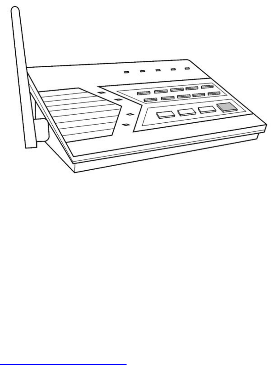
The Basics
Overview
Congratulations on your purchase of Skylink wireless security system, Model AM-001. This is a
complete wireless system which not only functions as a security system, but also monitors your
premises by giving you alert notification when the system is not armed. It is also a home
automation center, which allows you to remotely control household appliances and lightings,
even you are away from home. AM-001 can be controlled by dialing in from any touch tone
phone, which makes it even more convenient and powerful. Additional accessories such as
different kinds of sensor and controller can be added to suit your specific needs. This user’s
instructions will guide you through the whole setup procedure as well as all the programming
instructions. Please follow the instructions closely, you should find it very easy to setup the
system.
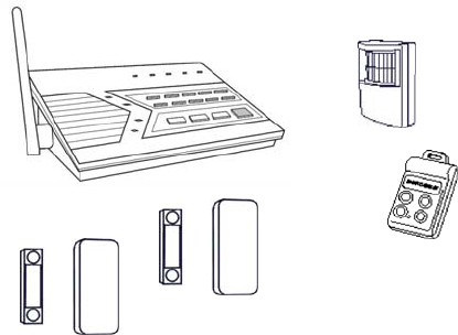
Door / Window
Sensor x 2
Motion
Sensor
Consol
Keychain
Remote
In the package, you should find the following items:
• One Control Panel
• One Motion Sensor
• Two Door / Window Sensors
• One Keychain Remote
• One AC adapter
• One telephone cord
• Batteries for all sensors
• Four AAA backup batteries for Control Panel
• Mounting hardware
Installation
Installing the Console
You must first determine where the control panel will be located. Please follow the criteria
below to select the ideal location for the control panel.
- Place it within few feet of an electrical outlet and phone jack
- Place it where it is easily accessible by you and other users
- Place it away from any doors or windows which could be accessed by non-intended
users
- Place it away from extreme temperature sources such as oven, stove and away from
large metal objects which could affect the wireless performance
After you have selected a location for the control panel, you are now ready to connect all the
necessary wires and ready to power up the unit.
1. Connect the phone line from the telephone jack to the back of the control panel where it
marks “Line”.
2. If you have another telephone that will be using the same telephone jack, you may connect
this telephone to the control panel by plugging in the phone cord to the “Phone” outlet on the
control panel.
3. Remove the battery cover on the bottom of the control panel with a Phillips screwdriver, and
insert 4 AAA alkaline batteries into the batteries holder. All the LED will flash once, and you
will hear 3 beeps. PWR LED will be on indicating the control panel is powered properly.
4. Plug in the AC adapter to the nearby electrical outlet and plug the other end to the socket on
back of the control panel.
5. Rotate the antenna to the upright position to ensure the best signal reception.
Program Passwords
Master Password can be used for programming, arming, disarming the system, and telephone
access. The default Master Password is [1234].
Secondary Password can be used for arming, disarming the system, and telephone access.
Secondary Password cannot be used for programming. The default Secondary Password is
[0000].
Duress Password is used when you are forcibly compelled to disarm the control panel. You
may enter the Duress Password. Entering the duress password will stop the siren from
sounding but the control panel will silently call the emergency phone numbers for help. The
default Duress Password is [3838]. You should definitely change this password and let all the
users know this password.
In order to change the password, follow the procedures below.
1. Press the PROG button on the side of the control panel, the [PROG] LED will be on..
2. Enter the current Master Password, [1234]. Enter [2], which represents Password
Programming.
3. Select the type of password you would like to change:
• Enter [1] for Master Password,
• Enter [2] for Secondary Password
• assword Enter [3] for Duress P
4. Enter new 4-digit password.
5. Enter new 4-digit password again, password accepted.
Program Emergency Phone Numbers
You can program up to 5 Emergency Phone Numbers. When the system is in panic situation,
he control panel will call 5 phone numbers and announce its status t
ide of the control panel, the [PROG] LED will be on. 1. Press the PROG button on the right s
2. Enter the current Master Password.
3. Enter [1], which represents Phone Number Programming.
4. Select the phone memory from 1 to 5. Note: In an emergency, the control panel will call
phone memory 1 as the first number, then phone memory 2 will be called, then memory 3, 4,
and 5. So it is recommended to program most important phone number in phone memory 1.
[Do not program police, 911 or fire station phone numbers into the control panel.]
5. Enter the phone number then press [Arm]. Note: You may enter a 3-second pause by
pressing [Mute] if needed. The phone number can be up to 29-digit long, including multiple
pause periods.
6. After entering the phone number, enter how many times you want the phone number to be
called, from 1 to 9 times. Press ARM to confirm.
7. After entering the redial, enter how many times you want the emergency message to be
played, from 1 to 9 times. It is recommended to play the message at least 2 times. Press
ARM, phone accepted.
WHEN PROGRAMMING EMERGENCY NUMBERS AND (OR) MAKING TEST
CALLS TO EMERGENCY NUMBERS:

1) Remain on the line and briefly explain to the dispatcher the reason for the call.
2) Perform such activities in the off-peak hours, such as early morning or late evenings.
Caution - To ensure proper operation, this equipment must be installed according to the
enclosed installation instructions. To verify that the equipment is operating properly and can
successfully report an alarm, this equipment must be tested immediately after installation, and
periodically thereafter, according to the enclosed test instructions.
Attention
This product is not an alarm system providing facilities to summon assistance, for use
by persons who can be considered to be living at risk. This product is not intended to for
use in health care signaling equipment or directly connect to central-station (Police,
Medical, Fire).

Installing the Door/Window Sensor
Window / Door Sensor is used to monitor doors or windows that open and close. When these
doors / windows are open or closed, the sensors will transmit a signal to the control panel to
notify the user. These sensors consist of 2 parts, one is the transmitter, the other is the magnet.
Remove the top cover of the sensor and insert the 3V lithium
battery to the sensor.
The transmitters should be
mounted on the door frame or
window frame by double sided
tape. The magnet should be
mounted on the door or window
by either double sided tape or
screws.
Make sure the arrow on the
magnet is aligned with the grey
marking on the transmitter.
(Show picture)
If the surface of the frame is flat enough, double-sided foam
tape is sufficient, otherwise, it is recommended to use the
mounting plate and screws as well. After mounting the
sensor, put the cover back on with the Houselink logo in the
upright position.
Try to mount the sensors as far away from the floor as possible to avoid damaging them.
Mounting the sensors at a higher position will also result in better operating range.
Do not mount the sensor to the exterior of the door / window, always mount the sensor to the
interior side of the door / window to avoid being damaged or stolen by non-intended users.
Testing: Open the door or window to trigger the sensor, the main unit will then alert you by
visual/audio indication and voice cue.

Installing the Motion Sensor
The motion sensor is most suitable for guarding the bedrooms. Use the motion sensor to
monitor the passage leading to the bedrooms or hallway.
You needed to power up the sensor first. Undo the
screw on the back of the motion sensor and remove
the cover of the battery compartment. Connect a
9V alkaline battery to the connector wire.
If you are going to install the motion sensor outdoor,
please change the sensitivity to low by changing the
sensitivity jumper from HI to LOW. You also needed
to change that zone to an Alert Zone. (Refer to p.
XX)
Then close the battery cover and re-insert the screw.
Mount the ball-head joint on the wall with screws provided. Slide the
back of the sensor into the ball-head joint. The mounting angle can be
adjusted.
Keep sensors within 30m (100 ft) of Control Panel.
Walk in the detected area. If the motion is detected, a read light inside the sensor will glow. If
the red light does not glow, motion has not been detected and you should re-position the sensor.
Repeated this procedure until your motion is detected. There should be no movement in the
detected area during the 20 seconds.
Note: When installing the motion sensor, avoid placing it near heat or cold producing devices
(i.e. A/C or furnace vents, fans, ovens, space heaters, etc). Air movement, especially caused by
changes in temperature may trigger the Motion Sensor and cause false alarms. Please
carefully test your Motion Sensor so that it will only be triggered by people.
Battery notes for the System
When you are reminded by the system that any sensors are in low battery, please change the
battery accordingly. The sensors, keychain remotes and accessories are generally designed to
have a battery life of around one year. Since there are large variations in different working
environment, we suggest replace new batteries every nine months.
The alkaline batteries in the main unit are expected to use as back up purpose in normal
working condition. We suggest you replace the alkaline batteries every nine months after you
have installed new batteries or right after a shortage of electricity in your premises.

Alarm & Alert Mode
Mode ARM LED When a sensor
Triggered
Application
Alert Off Notify by voice
announcement, beeping
and LED flashing.
When somebody in the home. The
system alerts you what is
happening around the users.
Arm On Siren goes off, LED
flashing and voice
announcement. Built-in
dialer calls for help.
When nobody in the home. The
system calls for help when a sensor
is triggered.
Alert mode
In Alert mode, the control panel will give you notification of the triggered sensor(s) by voice
announcement, unique beeping and LED flashing.
Number of beeps of Buzzer = Zone of the triggered sensor
Number of flashes of LED = Sensor number of the triggered sensor
Voice announcement = Tells you the zone and locations of the triggered sensor by human voice.
If zone 1 sensor 1 is triggered, you will hear a voice announcement “Zone 1 Sensor 1 triggered”
from the control panel. It will also emit one beep at a time, and the LED will flash once at a time.
If zone 3 sensor 2 is triggered, you will hear “Zone 3 Sensor 2 triggered. It will also emit 3
beeps at a time, and the LED will flash twice at a time.
Note: Each zone can program up to 2 sensors. There are 5 zones, so up to 10 sensors can be
programmed to the control panel.
For Door / Window sensor, alert notification (beeping and LED flashing) will continue until the
sensor is in the closed position, i.e. closing that window or door.
For Motion Detector, the alert notification (beeping and LED flashing) will last for 15 seconds for
every detected movement.
Mute
When the beeping becomes undesired, you can terminate the beeping in 3 different ways:
1) Manual mute by pressing the mute button
Pressing the mute button will terminate the beeping for all the activated sensors. For example,
if a window with a window sensor will be open for a long period of time, the continuous beeping
may become undesired. Pressing the mute button will temporary disable the beeping for this
sensor only, while it will still beep if other sensors are triggered. When the muted sensor is
closed and triggered again, the beeping will resume, i.e. if the window is closed and then re-
open, beeping will continue.
2) Change the buzzer mode to Alarm only
The beeping can be disabled for all zones and all times by changing the buzzer mode selector
(on the right side of the panel) to Alarm only. All sensor alert beeping will be ignored, while the
alarm siren will sound.
3) Enable Auto-Mute in Advanced Programming
This is to terminate the beeping for the specific zone(s) after it’s been beeped for 15 seconds.
That means beeping will be terminated automatically after 15 seconds if this feature is enabled
for that zone. Refer to Advanced Programming for more information on how to enable this
feature.
System Status
The control panel continuously monitors the system status as well as all the sensors status. It
will monitor which sensors are triggered, any low battery sensors, any mal-function sensors, or
a phone line failure.
In order to check the system status, user can press the “Status” button on the control panel,
voice announcement will be made regarding the system and sensor status. When the “Status”
button is pressed, you will be notified if any of the following events is occurring:
- System armed of disarmed
- Any triggered sensors
- Any sensors with low battery warning
- Any sensors with failure warning
- Phone line failure
Arm Mode
Arming the System
You should arm the system when you are the last person to leave the house. By arming the
system, the control panel will call the preprogrammed emergency phone numbers and siren will
sound when break-in occurs.
Note: Only arm the system when nobody is expected to be inside the premises. When
someone is expected to be within the premises, the system should not be armed.
To arm the system, follow the procedures below:
1. Press “Arm” button on the control panel when no sensors are triggered. You can also use
the keychain remote to arm the system by pressing button 1 on the remote.
Note:
• The control panel cannot be armed if there are triggered sensors. Make sure all
sensors are in closed position, i.e. (close all doors, windows, no movement should be
detected etc).
• The control panel can be armed if there are sensors with low battery or failure warning.
2. After pressing the “ARM” button, the “ARM” LED will flash and you will have 45 seconds to
leave the premises, this is called the exit delay. You will hear beeping during the exit delay
interval. The beeping rate will change from slow to fast, the faster the beep rate, the less
time you have left to leave the premises before the siren sounds.
3. When the exit delay expires, you will hear “System Armed” and beeping will stop and the
ARM LED will be on steadily. This indicates the system is now armed.
Note: The control panel can also be armed even nobody is home, with a touch tone phone.
Please refer to “Remote Operation by Telephone”
Disarming the system
If you trigger a sensor when entering a house with an armed control panel, you will trigger the
entry delay. You will have 30 seconds to disarm the control panel. Otherwise, the siren will
sound and emergency calls will be made. To disarm the control panel, follow the instructions
below.
1. If any sensors are now triggered when the control panel is armed, the system will beep for
30 seconds, and ARM LED will flash during this entry delay interval. The faster the beep,
the less time you have left to disarm the control panel before the siren sounds.
2. You must enter a valid password (either the Master Password, or Secondary Password) in
order to disarm the system before the entry delay expires. The system can also be
disarmed by pressing button 3 on the keychain remote.
3. When a valid password is entered, you will hear “System Disarmed” and the entry delay
beeping will stop, the ARM LED will be off.
Note:
• The control panel can also be armed even nobody is home, with a touch tone phone.
Please refer to “Remote Operation by Telephone”.
• If 3 consecutive incorrect passwords are entered, alarm will sound immediately and the
control panel will be in panic mode, and start calling the emergency phone numbers.
Disarming a triggered control panel
If you hear the announcement from the control panel “System Panic” after disarming the system,
that means at least one sensor was activated which caused the alarm to sound while you were
away. Following the procedures below to set the control panel back to standby mode.
1. There will be flashing LEDs indicating the sensor(s) that triggered the alarm. You may want
to check the condition of the triggered sensor(s), the sensor(s) may be damaged if there
were break-ins.
2. You need to reset the sensor by manually triggering it twice, i.e. open and close a door /
window sensor, or walk in front of the motion sensor. The LED representing that sensor will
then stop flashing.
3. You must now enter the password again on the control panel or press the button 3 of the
keychain remote, as an acknowledgement of the alarm event. This will set the control panel
back to standby mode.
Note: The control panel can also be disarmed even nobody is home, with a touch tone phone.
Please refer to “Remote Operation by Telephone”
Disarming under Duress
If you are forcibly compelled to disarm the control panel, you may enter the Duress Password.
Entering the duress password will stop the siren from sounding but the control panel will silently
call the emergency phone numbers for help. The called party will hear the voice announcement
“System Panic”.
Panic
Pressing the panic button will cause the siren to sound and outgoing calls will be made to the
preprogrammed phone numbers, “System Panic” will also be announced. This can be used in
any emergency situation. You can also press the panic button on the keychain remote to
perform the same function.
To stop the siren, user can enter either the Master Password, or the Secondary Password. You
can also press button 3 on the keychain remote to perform the same function. This will
terminate both the siren and the control panel from calling the rest of the emergency phone
numbers.
Receiving an emergency call
f you are on the list as one of the recipients of the emergeIncy call, you should read the
ey
1. r a
3.
re, entering the valid password is a
ay to acknowledge the emergency message. The control panel will continue to call the rest of
e phone numbers, unless the control panel is disarmed.
following instructions carefully. You should also notify all the persons you will be calling so th
know how to react when they receive the emergency call.
The control panel will call you when there are emergencies such as break-ins, smoke or fire
events, or a senior at home needs assistance.
When the phone rings at the calling location, the person who answers the phone will hea
message related to the emergency events, such as “System Panic”, or “Zone 1 Sensor 1
Triggered” etc. This message may be repeated several times depending on how it was
programmed.
2. After the message has been played for the certain number of times, the control panel will
ask for a valid password, you will hear “Enter Password”.
Enter the 4-digit password in order to have access to the control panel, such as to disarm
the alarm so it will stop the siren from sounding and terminate it from calling the rest of the
numbers. If a valid password is accepted, you will hear “Password Accepted”, otherwise,
you will hear “Password Failure”.
4. After entering the correct password, you can follow the “Phone Command” instructions to
perform the required tasks, such as disarm, check the system status again etc.
Note: Once the called party has entered a valid password, that person will not be called again,
ven the redial count is set to call more than once. Therefoe
w
th
Home Automation
By adding the optional Skylink receivers, such as the Light Switch Receiver Model SW-100R,
the control panel can be used to control up to 5 different receivers. There are 3 ways to control
these receivers:
1. Using the keypad on the control panel to operate these receivers manually
2. Calling in away from home using a touch tone phone (Refer to “Remote Operation by
Telephone”)
3. Setting up Event Trigger (Refer to Advanced Programming)
These receivers should be programmed to the control panel as device 1 to 5. Please follow the
programming instruction for additional devices for further information.
Light Switch Receiver Model SW-100R
To turn off a light with the control panel:
1. Press the device number button on the control panel, i.e. pressing 1 will turn off device 1,
pressing 2 will turn off device 2.
2. You will hear “Device X Off”, where X is the device number.
3. You will also see the PROG LED flashes, that indicate the control panel is sending out the
wireless signal to control the specific device.
4. If the receiver receives the signal, the control panel will announce “ Device Off Accepted”.
To turn on a light with the control panel:
1. Press the number below the device number that you would like to turn on, i.e. pressing 6 will
turn on device 1, pressing 7 will turn on device 2.
2. You will hear “Device X On”, where X is the device number.
3. You will also see the PROG LED flashes, that indicate the control panel is sending out the
wireless signal to control the specific device.
4. If the receiver receives the signal, the control panel will announce “Device On Accepted”.
Communication
Remote Operation by Telephone
The control panel can be operated while you are away from home. You can have access to the
control panel with any touch tone phone to perform a variety of operations, listed below.
• Arm
• Disarm
• Lights on / off
• Garage door open / close
• System status
• Disconnect
tion.
2. uring emergency, you can enter a valid password to have
access to the remote operations.
There are 2 ways you can have access to the remote phone opera
1. You can call the control panel when you are away from home;
When the control panel calls you d

To access the control panel away from home
1. Call your home phone number, or the number that the control panel is connected to.
Hang u2. p after hearing the second ring.
4. need to enter
hear “Password Accepted”, otherwise, you will hear “Password Failure”.
ou can have access to all the operations listed below:
able 1: Remote Phone Operations
rgency phone
umbers, the called party will hear the emergency message, it will then ask for a password. If a
valid password is entered, the operations listed in Table 1 will be available.
ds, including
ow the program additional sensors, remotes, how the buzzer behaves for different zones,
The follow advanced programming fields.
Options Com
3. Wait at least 10 seconds, but not more than 1 minute, then call your home phone number
again.
The control panel will pick up the phone call and ask for a password. You
either the Master Password or Secondary Password. If the password is correct, you will
5. Once the password is accepted, y
T
System Operation Phone
Command Description
Turn on device X X + [#]
on, will hear
Turn lights
confirmation, “Device On
Accepted”
Turn off device X X + [*]
Turn lights off, will hear
f confirmation, “Device Of
Accepted”
Check system status [8] + [#] Will hear system status
announcement
Arm [7] + [#] Will hear “System Armed”
Disarm [9] + [#] Will hear “System Disar
med”
The same operations can be performed when the control panel calls the eme
Disconnect [0] + [#] Phone line disconnect
n
Advanced Programming
You can customized the control panel in different configurations to suit your nee
h
event trigger setting etc.
ings are the
Programming mand
Learn Sensor [PROG] + [3]
Learn Remote or Receiver [PROG] + [4]
Beep / Alarm [PROG] + [5]
Auto Mute [PROG] + [6]
Event Trigger [PROG] + [7]

Alert Zone [PROG] + [8]
Erase Sensor [PROG] + [9]
Erase Remote / Receiver [PROG] + [0]
Learn Sensor
t trigger,
xplanation for each zone dependent feature can be found in Advanced
rogramming.
ensor Location Selection Guide
bled. It is not possible to enable a zone dependent feature for sensor 1 only, but
ne
2.
3.
able
es.
Detailed explanation for each feature can be found in Advanced Programming.
en
You can program up to 10 sensors to the control panel. There are 5 zones, each zone can
program 2 sensors. Before programming a sensor, you must decide which sensor location
(zone number and sensor number) you would like to program the sensor to. It is strongly
recommended that you refer to “Sensor Location Selection Guide” and study the 4 zone
dependent features before deciding which sensor location you would like to program the new
sensors to. The 4 zone dependent features are: 1) buzzer sound, 2) auto mute, 3) even
) alert zone. E4
P
S
You can program up to 10 sensors to the control panel. There are 5 zones and there are some
zone dependent features. Zone dependent feature means all the sensors in that zone will
operate based on the setting for that zone. So if you program 2 sensors into one zone, those 2
sensors will react in the same manner for those zone dependent features. For example, if you
enable the Auto-Mute feature for zone 1, both zone 1 sensor 1, and zone 1 sensor 2 will have
his feature enat
not sensor 2.
Therefore, the followings are some suggestions of how you should select the sensor location.
1. Check all the zone dependent features, and determine if you would like to enable any o
of them.
If you decide not to enable any zone dependent features and keep the factory default
setting, you can simply program the sensor to any sensor location based on your own
preference. Omit the following steps.
If you decide to enable some of the zone dependent features, check Table 2 below. Circle
the zone dependent feature selections. If there are features that you would like to en
for more than 2 sensors, you need to select more than one zone for those featur
Sensor 1 Sensor 2 Zone Depend t Features
Location Location Auto Mute Beep / Alarm Event Trigger Alert
Zone 1 Beep / Alarm Y / N Disabled / On / Off Y / N
Zone 2 Beep / Alarm Y / N Disabled / On / Off Y / N
Zone 3 Beep / Alarm Y / N Disabled / On / Off Y / N
Zone 4 Beep / Alarm Y / N Disabled / On / Off Y / N
Zone 5 Beep / Alarm Y / N Disabled / On / Off Y / N

4. Once you have filled out the table, it should look something like this.
enSensor 1 Sensor 2 Zone Depend t Features
Auto Mute
Location Beep / Alarm Event Trigger Alert Location
Zone 1 Front Door Front Window Beep / Alarm Y / N Disabled / On / Off Y / N
Zone 2 Kitchen Motion Beep / Alarm Y / N Disabled / On / Off Y / N
Zone 3 Back Door Y / N
Beep / Alarm Disabled / On / Off Y / N
Zone 4 Backyard Motion Beep / Alarm Y / N Disabled / On / Off Y / N
Zone 5 Basement Water Motion Beep / Alarm Y / N Disabled / On / Off Y / N
Basement
You can now refer to each column representing the zone dependent features, to program
each zone with the selected feature. For example, Auto Mute feature is only enabled for
zone 3, when you are in the auto mute programming, you should set it so that auto mute is
only enabled for zone 3, the rest of the zone should hav
5.
e this feature disabled. Repeat this
step for all 4 zone dependent features programming.
earn Sensor – continue
r to
e control panel. To learn a sensor into the control panel, follow the instructions below.
6. sword is
e emitted and [PROG] LED will be off.
8. once, some of
or.
9.
1 for
ee Fig. X. After
selecting the zone and sensor numbers, that zone LED will be on.
L
After studying the “Sensor Location Selection Guide”, you may proceed to learn the senso
th
5. Press the [PROG] button on the side of the control panel, the [PROG] LED will be on.
Enter the current Master Password. Control panel will emit 3 beeps if the valid pas
entered, otherwise a single long beep will b
7. Enter [3], which represents “learn sensor”.
Notice all 5 zone LEDs, some of them may be off, some of them may flash
the may flash twice. The LED flashing represents the occupied sensors.
• If the zone LED remains off, that indicates that zone is not occupied by any sens
• If the zone LED flashes once, that indicates sensor 1 of that zone is occupied.
• If the zone LED flashes twice, that indicates sensor 2 of that zone is occupied.
You may now select a zone and sensor location to program the sensor to. Select the zone
and sensor number by pressing on to button 1 to 0. Buttons 1 to 5 represent sensor
zones 1 to 5. Buttons 6 to 0 represent sensor 2 for zones 1 to 5. S
Sensor 1 Sensor 2
Zone 1 Button [1] Button [6]
Zone 2 Button [2] Button [7]
Zone 3 Button [3] Button [8]
Zone 4 Button [4] Button [9]
Zone 5 Button [5] Button [0]

10. Activate the sensor, the control panel will beep and you will hear “Zone _ Sensor _
Accepted” if the sensor is programmed, the [PROG] LED will be off. To program another
sensor, repeat the above steps.
ote: If an occupied sensor location is selected, the new sensor will replace the old one.
dditional keychain or keypad remote can be programmed to the control. You may also
odel SW-100R or Garage
e programmed
the control panel.
Receivers should be programmed to Device 1 to Device 5.
ll
1.
2. panel will emit 3 beeps if the valid password is
ente ,
3. Enter [4] arn Keychain / Receiver”. Notice all 5 zone LEDs, some of
them a
flashing
N
Learn Remote / Receiver
A
program additional receivers such as the Light Switch Receiver, M
Door Receiver GD-101R. Maximum of 5 keychain remotes and 5 receivers can b
to
•
• Keychain or keypad remote should be programmed to Device 6 to Device 0.
ow the instructions below to program remotes / receivers. Fo
Press the [PROG] button on the side of the control panel, the [PROG] LED will be on.
Enter the current Master Password. Control
red otherwise a single long beep will be emitted and [PROG] LED will be off.
, which represents “Le
m y be off, some of them may flash once, some of the may flash twice. The LED
represents the occupied sensors.
• If the zone LED remains off, that indicates that zone is not occupied by any
keychain / receiver.
• If the zone LED flashes once, that indicates a receiver has occupied that device.
Zone 1 LED flashes once means Device 1 is occupied.
• If the zone LED flashes twice, that indicates a keychain / keypad remote has
occupied that zone. Zone 1 LED flashes twice means Device 6 is occupied.
For programming a receiver, select a device number from Device 1 to Device 5. Press and 4.
ce on
5.
selected, that zone LED will be on steadily. You
can now transmit a signal by pressing one of the buttons from the keychain.
. The control panel will beep and you will hear “Device X Accepted” if the device is
programmed and the [PROG] LED will be off. To program another remote / receiver, repeat
hold the learn button on the receiver continuously, you will see the LED flashing rapidly. To
select device 1, press button 6. The LED stop flashing indicate the receiver has received
the signal. Then press button 1 on control panel for device 1. Once a device is selected,
that zone LED will be on steadily. . You can now transmit a signal by pressing on
learn button on the receiver.
For programming a keychain, select a device number from Device 6 to Device 0. To select
device 6, press button 6. Once a device is
6
the above steps.
Note: If an occupied device is selected, the new sensor will replace the old one.

Zone Dependent Setting – Beep / Alarm
r can customize the audio warning so that when a sensor is triggered, it may bee
se
secu
• alarm
immediately, but it will stop when the sensor is back to normal (door closes). It
umbers since it is not armed.
without entry delay, it is called
tered.
l z the factory.
•
• or is not located outdoor
1. Pre th
2. Enter the current Master Password. Control panel will emit 3 beeps if the valid password is
3.
ents the current beep / alarm
setting.
• If the zone LED flashes, that ind the zon rammed to “Beep”.
• If the zone LED remains steadily on, that indicates the zone is programmed to
“Alarm”.
4. To change the setting between beep and alarm, press buttons 1 to 5 will set that zone to
beep. Pressing buttons 6 to 0 will set that zone to alarm. Refer to Fig X. After making the
change, notice the stat zone es a
Beep Alarm
Up, or an
alarm may sound immediately. Depending on whether the control panel is in alert mode or
rity mode, the audio warning will be different.
Alert mode: If a sensor is triggered (i.e. opening a door) with the alarm feature on, the
will sound
control panel will not call the emergency phone n
Security mode: If a sensor is triggered (i.e. opening a door) with the alarm feature on and •
the system is armed, the siren will sound immediately
“Instant Alarm”. The siren will not stop until the siren timeout or a valid password is en
Control panel will call the emergency phone numbers to notify the users of the alarm
situation.
l ones were programmed to beep at A
It is recommended to program a zone into Alarm mode if:
• You need immediate attention if that sensor is triggered, such as flood sensor, smoke
sensor etc.
The sensor will not be triggered on a daily basis
The sens
ss e [PROG] button on the side of the control panel, the [PROG] LED will be on.
entered, otherwise a single long beep will be emitted and [PROG] LED will be off.
Enter [5], which represents “Beep / Alarm” setting. Notice all 5 zone LEDs, some of them
may be off, some of them may flash. The LED flashing repres
icates e is prog
us of the LED chang s well.
Zone 1 Button [1] Button [6]
Zone 2 Button [2] Button [7]
Zone 3 Button [3] Button [8]
Zone 4 Button [4] Button [9]
Zone 5 Button [5] Button [0]
5. You are allow to make unlimited changes before programming is quit. Once you are
satisfied with the settings, press [PROG] to quit programming and the settings will be saved.

Zone Dependent Setting – Auto Mute
Once a sensor is triggered, audio warning will be emitted, either beep or alarm. For example, if
n for
This fea re
1.
current Master Password. Control panel will emit 3 beeps if the valid password is
entered, otherwise a single long beep will be emitted and [PROG] LED will be off.
3. Enter [6], which represents “A ti ome of them may
be off, some of them may flash. The LED flashing represents the current auto mute setting.
• If the zone LED flashes, that indicates auto mute is disabled
• If the z remains s
4. To change the setting between au ble and disa buttons 1 to 5 will
disable auto mute for those zones buttons 6 to le auto mute for those
zones. Refer to Fig X. After maki notice the status of the zone LED changes
as well.
a door is opened, the audio warning will not stop until the door is closed. If the door is ope
2 hours, the audio warning will go on for 2 hours. There are times that this is not desired. With
the auto mute feature enabled, the audio warning will go on for only 15 seconds. After that, if
sensor remains open, only the zone LED will flash to indicate the sensor is triggerethe d. Audio
warning will go on again if the sensor is closed and open again.
tu was disabled for all zones at the factory.
To enable auto mute feature, follow the instructions below.
Press the [PROG] button on the side of the control panel, the [PROG] LED will be on.
Enter the 2.
uto Mute” setting. No ce all 5 zone LEDs, s
one LED teadily on, that indicates auto mute is enabled
to mute ena ble, press
. Pressing 0 will enab
ng the change,
Disable Auto Mute Enable Auto Mute
Zone 1 Button [1] Button [6]
Zone 2 Button [2] Button [7]
Zone 3 Button [3] Button [8]
Zone 4 Button [4] Button [9]
Zone 5 Button [5] Button [0]
5. You are allowed to make unlimited changes before programming is quit. Once you are
satisfied with the settings, press [PROG] to quit programming and the settings will be saved.
ically. It is called Event Trigger.
nel will transmit a signal to activate the
en the door sensor is open, turn the
s
Even , you
can program device 1 to be on or off when zone 1 sensor(s) is triggered. You can also program
device 2 to be on / off when zone 2 sensor(s) is triggered.
Zone Dependent Setting – Event Trigger
Home Automation is one of the features that makes this system so powerful. You can control
p to 5 different devices not only manually, but also automatu
That means when a sensor is triggered, the control pa
esignated receiver. Applications include: d
• Lights on when you open the front door (wh
lighting receiver on)
• Lights on when you walk into the kitchen (when the motion sensor in the kitchen i
activated, turn the lighting receiver on)
t trigger is only applicable to the sensors and receiver in the same zone. For example

feature was disabled for all zones at the factory. This
To en le
1. Press e [PROG] LED will be on.
2.
is en D will be off.
ab event trigger, follow the instructions below.
the [PROG] button on the side of the control panel, th
Enter the current Master Password. Control panel will emit 3 beeps if the valid password
tered, otherwise a single long beep will be emitted and [PROG] LE
3. Enter [7], which represents “Event Trigger” setting. Notice all 5 zone LEDs, some of them
may be off, some of them may flash once, some of them may be on steadily. The LED
flashing represents the current event trigger setting.
• If the zone LED is off, that indicates event trigger is disabled.
• If the zone LED flashes, that indicates event trigger is enabled, and it will turn off the
corresponding device when the sensor(s) is activated
• If the zone LED remains steadily on, that indicates event trigger is enabled, and
turn
it will
on the corresponding device when the sensor(s) is activated
. To change the event trigger setting, press buttons 1 to 5 will d
zones. P ssing buttons 6 event trigger for those zones. However, even
this feature is enabled, you still have to select whether you want to turn that device on or
off when the sensor(s) is trig ssing buttons [6] to [0] will toggle the setting
between on and off. For exa LED is currently vent trigger for zone 2
is enable with the Off signal, you can press button [7] to change it to the On signal.
Pressing [7] again will change it back to Off signal. Refer to Fig X. After making the
change, notice the status of the zone LED changes as w
Disable Event
Trigger Enable Event Trigger
(Toggle between Off
4isable event trigger for those
re to 0 will enable
gered. Pre
mple, if the showing e
ell.
and On)
Zone 1 Button [1] Button [6]
Zone 2 Button [2] Button [7]
Zone 3 Button [3] Button [8]
Zone 4 Button [4] Button [9]
Zone 5 Button [5] Button [0]
5. You are allowed to make unlimited changes before programming is quit. Once you are
satisfied with the settings, press [PROG] to quit programming and the settings will be
ote: If event triggered is enabled for a door sensor, which turn lights on when it is open, this
ave
n operate in 2 different modes, 1) Alert Mode, 2)
nd immediately (with instant
not want to trigger the alarm when the system
saved.
N
feature will not be activated during exit delay. Since during exit delay, users suppose to le
the premises and therefore lights will not be turned on. However, if the event triggered is
enabled to turn lights off, it will be activated during exit delay.
Zone Dependent Setting – Alert Zone
As explained earlier, the control panel ca
Security Mode. In security mode, when a sensor is triggered, the control panel will need to be
disarmed either after 30 seconds (with entry delay), or siren will sou
alarm). However, there are sensors that you do

is armed. Such as outdoor motion sensor, or any other sensors that you only want to give you
lert notification. Under such circumstances, zone(s) can be program to react only when the
red when the control panel is in security
ode.
is recommend to enable alert zone if:
This
To enabl le
2.
. lert Zone” setting. Notice all 5 zone LEDs, some of them
may be off, so e of them m sh urrent alert zone
setting.
• If the flashes, s alert zone
• If the zone LED remains steadily on, that indicates alert zone is enabled
4. To change the setting between alert zone enable and disable, press buttons 1 to 5 will
disable alert z ure for tho
feature for those zones. Refer to r making th otice the status of the
zone LED cha well.
a
control panel is in alert mode, these zones will be igno
m
It
• You do not consider the sensors in that zone are emergency
• Sensors in that zone are located outdoor
• When nobody is home, you do not want to know the status of the sensors in that zone
feature was disabled for all zones at the factory.
e a rt zone feature, follow the instructions below.
1. Press the [PROG] button on the side of the control panel, the [PROG] LED will be on.
Enter the current Master Password. Control panel will emit 3 beeps if the valid password
is entered, otherwise a single long beep will be emitted and [PROG] LED will be off.
Enter [8], which represents “A3
m ay flash. The LED fla ing represents the c
zone LED that indicate is disabled
one feat se zones. Pressing buttons 6 to 0 will enable alert zone
Fig X. Afte e change, n
nges as
Disable Alert Zone Enable Alert Zone
Zone 1 Button [1] Button [6]
Zone 2 Button [2] Button [7]
Zone 3 Button [3] Button [8]
Zone 4 Button [4] Button [9]
Zone 5 Button [5] Button [0]
. You are allowed to make unlimited ch5 anges before programming is quit. Once you are
Procee the
3.
4. f
satisfied with the settings, press [PROG] to quit programming and the settings will be
saved.
Erase Sensor
d followings to erase a sensor.
1. Press the [PROG] button on the side of the control panel, the [PROG] LED will be on.
2. Enter the current Master Password. Control panel will emit 3 beeps if the valid password
is entered, otherwise a single long beep will be emitted and [PROG] LED will be off.
Enter [9], which represents “Erase Sensor”.
Notice all 5 zone LEDs, some of them may be off, some of them may flash once, some o
the may flash twice. The LED flashing represents the occupied sensors.

• If the zone LED remains off, that indicates that zone is not occupied by any sensor.
• If the zone LED flashes once, that indicates sensor 1 of that zone is occupied.
• If the zone LED flashes twice, that indicates sensor 2 of that zone is occupied.
5. You may now select which sensor lo ase zone and sensor number
by pressing buttons [1 utton prese
6 to 0 represent sens ones r sel ensor location, you will
hear 3 beeps and “Zone_ Sensor_ E ory”. rms the selected sensor
has been erased, and OG] L ff. To erase another sensor, repeat the
above steps.
Sensor 1 Sensor 2
cation to er . Select the
] to [0]. B s 1 to 5 re
1 to 5. Afte
nt sensor 1 for zones 1 to 5. Buttons
ecting the sor 2 for z
mpty Mem This confi
the [PR ED will be o
Zone 1 Button [1] Button [6]
Zone 2 Button [2] Button [7]
Zone 3 Button [3] Button [8]
Zone 4 Button [4] Button [9]
Zone 5 Button [5] Button [0]
e Remotes / Receiver E
ras
Follow the instructions below to erase keychain or keypad remotes / receivers.
1. Press the [PROG] button on the side of the control panel, the [PROG] LED will be on.
2. Enter the current Master Password. Control panel will emit 3 beeps if the valid password
is entered, otherwise a single long beep will be emitted and [PROG] LED will be off.
3. Enter [0], which represents “Erase Keychain / Receiver”. Notice all 5 zone LEDs, some of
them may be off, some of them may flash once, some of the may flash twice. The LED
flashing represents the occupied sensors.
• If the zone LED remains off, that indicates that zone is not occupied by any keychain /
receiver.
• If the zone LED flashes once, that indicates a receiver has occupied that device. Zone 1
LED flashes once means Device 1 is occupied.
• If the zone LED flashes twice, that indicates a keychain / keypad remote has occupied that
zone. Zone 1 LED flashes twice means Device 6 is occupied.
4. To erase a receiver, enter a device number from Device 1 to Device 5. To select device 1,
press button 1. Once a device is selected, you will hear 3 beeps and “Device_ Empty
Memory”.
5. To erase a keychain, enter a device number from Device 6 to Device 0. To select device 6,
press button 6. Once a device is selected, you will hear 3 beeps and “Device_ Empty
Memory”.
6. To erase another remote / receiver, repeat the above steps.
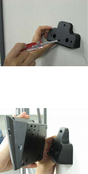
Mounting the Control Panel on the wall
1. Place the mounting bracket at the desired location.
2. Mount the bracket onto the wall with 2 screws.
3. Attached the Control Panel securely to the mounting bracket.

FCC Information
Consumer Information:
a) This equipment complies with Part 68 of the FCC rules and the requirements adopted by the
ACTA. On the bottom of this equipment is a label that contains, among other information, a
product identifier in the format US:AAAEQ##TXXXX. If requested, this number must be
provided to the telephone company.
b) An applicable certification jacks Universal Service Order Codes (USOC) for the equipment is
provided (i.e., RJ11C) in the packaging with each piece of approved terminal equipment.
c) A plug and jack used to connect this equipment to the premises wiring and telephone
network must comply with the applicable FCC Part 68 rules and requirements adopted by
the ACTA. A compliant telephone cord and modular plug is provided with this product. It is
designed to be connected to a compatible modular jack that is also compliant. See
installation instructions for details.
d) The REN is used to determine the number of devices that may be connected to a telephone
line. Excessive RENs on a telephone line may result in the devices not ringing in response
to an incoming call. In most but not all areas, the sum of RENs should not exceed five (5.0).
To be certain of the number of devices that may be connected to a line, as determined by
the total RENs, contact the local telephone company. [For products approved after July 23,
2001, the REN for this product is part of the product identifier that has the format
US:AAAEQ##TXXXX. The digits represented by ## are the REN without a decimal point
(e.g., 03 is a REN of 0.3). For earlier products, the REN is separately shown on the label.]
e) If this equipment
AM-001 causes harm to the telephone network, the telephone company will
notify you in advance that temporary discontinuance of service may be required. But if
advance notice isn't practical, the telephone company will notify the customer as soon as
possible. Also, you will be advised of your right to file a complaint with the FCC if you believe
it is necessary.
f) The telephone company may make changes in its facilities, equipment, operations or
procedures that could affect the operation of the equipment. If this happens the telephone
company will provide advance notice in order for you to make necessary modifications to
maintain uninterrupted service.
g) Should you experience trouble with this equipment, please contact Skylink Customer
Support at 1-800-304-1187 for repair or warranty information. If the equipment is causing
harm to the telephone network, the telephone company may request that you disconnect the
equipment until the problem is resolved.
h) Please follow instructions for repairing if any (e.g. battery replacement section); otherwise do
not alternate or repair any parts of device except specified.
i) Connection to party line service is subject to state tariffs. Contact the state public utility
commission, public service commission or corporation commission for information.
j) NOTICE: If your home has specially wired alarm equipment connected to the telephone line,
ensure the installation of this model AM-001 does not disable your alarm equipment. If you
have questions about what will disable alarm equipment, consult your telephone company or
a qualified installer.
NOTICE: According to telephone company reports, AC electrical surges, typically resulting from
lightning strikes, are very destructive to telephone equipment connected to AC power sources.
To minimize damage from these types of surges, a surge arrestor is recommended.
FCC STATEMENT
This device complies with Part 15 of the FCC Rules. Operation is subject to the following two
conditions: (1) This device may not cause harmful interference, and (2) This is device must
accept any interference received, including interference that may cause undesired operation.
Warning: Changes or modifications to this unit not expressly approved by the party responsible
for compliance could void the user’s authority to operate the equipment.
NOTE: This equipment has been tested and found to comply with the limits for a Class B digital
device, pursuant to Part 15 of the FCC Rules. These limits are designed to provide reasonable
protection against harmful interference in a residential installation. This equipment generates,
uses and can radiate radio frequency energy and, if not installed and used in accordance with
the instructions, may cause harmful interference to radio communications.
However, there is no guarantee that interference will not occur in a particular installation. If this
equipment does cause harmful interference to radio or television reception, which can be
determined by turning the equipment off and on, the user is encouraged to try to correct the
interference by one or more of the following measures:
□ Reorient or relocate the receiving antenna.
□ Increase the separation between the equipment and receiver.
□ Connect the equipment into an outlet on a circuit different from that to which the receiver
is connected.
□ Consult the dealer or an experienced radio/TV technician for help.
Customer Service
17 Sheard Avenue,
Brampton,
Ontario,
L6Y 1J3
Canada
Toll Free 1-800-304-1187

AAA Plus™ Accessories
The AAA Plus™ receiver can work with up to 10 sensors and 5 remote controls. It can also
used to trigger unlimited number of Houselink® secondary alarm and emergency dialer.
Sensor
WD-101
Door/Window Sensor
FS-101
Water Sensor
GS-102
Garage Door Sensor (Europe)
GS-101
Garage Door Sensor (North America)
PS-101
Motion Sensor
* suitable for indoor and outdoor (alert
mode) use.
Remote Control & Panic
Button
4B-434
Keychain Remote
PT-434 Panic Transmitter
KP-434 Keypad Remote
Wireless Switch for
Automation
SW-100R Wireless Switch Receiver (North
America)
SW-100R (same model
number for US and
EU?)
Wireless Switch Receiver (Europe)
External devices
RP-434
Repeater
* extend the wireless operating range
between receiver and all other
accessories.
AS-101
Audio Alarm
* used as external alarm.
AD-433S / AD-433SE Emergency Dialer (North America /
Europe)
SDO Series of
Products
Swing Door Operator
Coming soon??
Please visit www.skylinkhome.com or contact us at support@skylinkhome.com for more
information of how to fully utilize your AAA Plus™ system.

=====================================================================
IMPORTANT SAFETY INSTRUCTIONS
When using your telephone equipment, basic safety precautions should always be followed to reduce
the risk of fire, electric shock and injury to persons, including the
following:
1. Do not use this product near water, for example, near a bath tub, wash bowl, kitchen sink or
laundry tub, in a wet basement or near a swimming pool.
2. Avoid using a telephone (other than a cordless type) during an electrical storm. There may be a
remote risk of electric shock from lightning.
3. Do not use the telephone to report a gas leak in the vicinity of the leak.
4. Use only the power cord and batteries indicated in this manual. Do not dispose of batteries in a fire.
They may explode. Check with local codes for possible special disposal instructions.
5. Plug the adaptor to the socket-outlet that near the equipment and shall be easily accessible.
USE ONLY US: Sunnyway, type no. SW-613, rated 6V 1300mAh. Sealed Lead-Acid battery.
EU: GP type no. 5MR1300AAH4L, rated 6V 1300mAh Ni-MH battery
SAVE THESE INSTRUCTIONS
=======================================================================
IMPORTANTES MESURES DE SÉCURITÉ
Certaines mesures de sécurité doivent être prises pendant I,utilisation de
matérial téléphonique afin de réduire les risques d,incendie, de chocélectrique
et de blessures. En voici quelquesunes;
1. Ne pas utiliser I,appareil près de I,eau, p.ex., Près d,une baignoire, d,un lavabo, d,un évier de
cuisine, d,un bac à laver, dans un soussol humide ou près d,une piscine.
2. Éviter d,utiliser le téléphone ( sauf s,il s,agit d,un appareil sans fil ) pendant un orage
électrique. Ceci peut présenter un risque de choc électrique causé par la foudre.
3. Ne pas utilise I,appareil téléphonique pour signaler une fuite de gaz s,il est situé près de la
fuite.
4. Utiliser seulement le cordon d, alimentation et le type de piles indiqués dans ce manuel. Ne pas
jeter les piles dans le feu: elles peuvent exploser. Se conformer aux règlements pertinents
quant à I,élimination des piles.
5. La socklet-sortie sera installée près de l,équipement et sera facilement accessible.
6. ATTENTION- ll y a danger d’explosion s’il y a remplacement incorrect de la batterie. Remplacer
uniquement avec une batterie du meme type ou d’un type équivalent recommandé par le
constructeur. Mettre au rebut les batteries usagées conformément aux instructions du fabricant.
US: Sunnyway, type no. SW-613, rated 6V 1300mAh. Sealed Lead-Acid battery.
EU: GP type no. 5MR1300AAH4L, rated 6V 1300mAh Ni-MH battery.
CONSERVER CES INSTRUCTIONS
=====================================================================

IC Statement
''This product meets the applicable Industry Canada technical specifications.”
Before installing this equipment, users should ensure that it is permissible to be connected to the
facilities of the local telecommunications company. The equipment must also be installed using
an acceptable method of connection. In some cases, the company’s inside wiring associated
with a single line individual service may be extended by means of a certified connector assembly
(telephone extension cord). The customer should be aware that compliance with the above
conditions may not prevent degradation of service in some situations.
Repairs to certified equipment should be made by an authorized Canadian maintenance facility
designated by the supplier. Any repairs or alterations made by the user to this equipment, or
equipment malfunctions, may give the telecommunications company cause to request the user to
disconnect the equipment.
Users should ensure for their own protection that the electrical ground connections of the power
utility, telephone lines and internal metallic water pipe system, if present, are connected together.
This precaution may be particularly important in rural areas.
Caution: Users should not attempt to make such connections themselves, but should contact the
appropriate electric inspection authority, or electrician, as appropriate.
''The Ringer Equivalence Number is an indication of the maximum number of terminals
allowed to be connected to a telephone interface. The termination on an interface may
consist of any combination of devices subject only to the requirement that the sum of the
Ringer Equivalence Numbers of all the devices does not exceed five.''

Content
The Basics ...................................................................................................................................5
Overview ..................................................................................................................................5
Installation....................................................................................................................................6
Installing the Console ...............................................................................................................6
Program Passwords .................................................................................................................7
Program Emergency Phone Numbers......................................................................................7
Installing the Door/Window Sensor ..........................................................................................9
Installing the Motion Sensor ...................................................................................................10
Battery notes for the System ..................................................................................................10
Alarm & Alert Mode....................................................................................................................11
Alert mode..................................................................................................................................11
Mute .......................................................................................................................................11
System Status ........................................................................................................................12
Arm Mode ..................................................................................................................................13
Arming the System .................................................................................................................13
Disarming the system.............................................................................................................13
Disarming a triggered control panel........................................................................................14
Disarming under Duress.........................................................................................................14
Panic ......................................................................................................................................14
Receiving an emergency call .....................................................................................................15
Home Automation ......................................................................................................................13
Receiver Model SW-100R ......................................................................................................13
Communication ......................................................................................................................16
Remote Operation by Telephone ...........................................................................................16
To access the control panel away from home ........................................................................17
Advanced Programming.............................................................................................................17
Learn Sensor..........................................................................................................................18
Sensor Location Selection Guide ...........................................................................................18
Learn Sensor – continue ........................................................................................................19
Learn Remote / Receiver........................................................................................................20
Zone Dependent Setting – Beep / Alarm................................................................................21
Zone Dependent Setting – Auto Mute ....................................................................................22
Zone Dependent Setting – Event Trigger ...............................................................................22
Zone Dependent Setting – Alert Zone ....................................................................................23
Erase Sensor..........................................................................................................................24
Erase Remotes / Receiver......................................................................................................25
Wallmount Installation ………………………………………………………………………………..25
FCC Information ………………………………………………………………………………………..29
Accessories …………………………………………………………………………………………….30
The Basics
Overview
Congratulations on your purchase of Skylink wireless security system, Model AM-002. This is a
complete wireless system which not only functions as a security system, but also monitors your
premises by giving you alert notification when the system is not armed. It is also a home
automation center, which allows you to remotely control household appliances and lightings,
even you are away from home. AM-002 can be controlled by dialing in from any touch tone
phone, which makes it even more convenient and powerful. Additional accessories such as
different kinds of sensor and controller can be added to suit your specific needs. This user’s
instructions will guide you through the whole setup procedure as well as all the programming
instructions. Please follow the instructions closely, you should find it very easy to setup the
system.
In the package, you should find the following items:
• One Control Panel
• One Motion Sensor
• Two Door / Window Sensors
• One Keychain Remote
• One AC adapter
• One telephone cord
• Batteries for all sensors
• One backup battery for Control Pan .
6V Ni-MH battery for EU region
• Mounting hardware
el – 6V Lead-Acid type for US region
Installation
Installing the Console
You must first determine where the control panel will be located. Please follow the criteria
below to select the ideal location for the control panel.
- Place it within few feet of an electrical outlet and phone jack
- Place it where it is easily accessible by you and other users
- Place it away from any doors or windows which could be accessed by non-intended
users
- Place it away from extreme temperature sources such as oven, stove and away from
large metal objects which could affect the wireless performance
After you have selected a location for the control panel, you are now ready to connect all the
necessary wires and ready to power up the unit.
1. Connect the phone line from the telephone jack to the back of the control panel where it
marks “Line”.
2. If you have another telephone that will be using the same telephone jack, you may connect
this telephone to the control panel by plugging in the phone cord to the “Phone” outlet on the
control panel.
3. Remove the battery cover on the bottom of the control panel with a Phillips screwdriver, and
insert 6V backup battery pack. All the LED will flash once, and you will hear 3 beeps. PWR
LED will be on indicating the control panel is powered properly.
4. Plug in the AC adapter to the nearby electrical outlet and plug the other end to the socket on
back of the control panel.
5. Rotate the antenna to the upright position to ensure the best signal reception.
6. To install battery (for US version), pry off the battery cover. Plug the RED battery wire to the
battery terminal (+). Plug the BLACK battery wire to the battery terminal (-). Cover the
battery cover and secure by the screw.
7. To install battery (for EU version), pry off the battery cover. Mate the battery connector from
the battery to the wires from the main unit. Cover the battery cover and secure by the screw.
Program Passwords
Master Password can be used for programming, arming, disarming the system, and telephone
access. The default Master Password is [1234].
Secondary Password can be used for arming, disarming the system, and telephone access.
Secondary Password cannot be used for programming. The default Secondary Password is
[0000].
Duress Password is used when you are forcibly compelled to disarm the control panel. You
may enter the Duress Password. Entering the duress password will stop the siren from
sounding but the control panel will silently call the emergency phone numbers for help. The
default Duress Password is [3838]. You should definitely change this password and let all the
users know this password.
In order to change the password, follow the procedures below.
1. Press the PROG button on the side of the control panel, the [PROG] LED will be on..
2. Enter the current Master Password, [1234]. Enter [2], which represents Password
Programming.
3. Select the type of password you would like to change:
• Enter [1] for Master Password,
• Enter [2] for Secondary Password
• assword Enter [3] for Duress P
4. Enter new 4-digit password.
5. Enter new 4-digit password again, password accepted.
Program Service/Important Phone Numbers
You can program up to 5 Phone Numbers. When the system is in panic situation, the control
anel will call 5 phone numbers and announce its status p
ide of the control panel, the [PROG] LED will be on. 1. Press the PROG button on the right s
2. Enter the current Master Password.
3. Enter [1], which represents Phone Number Programming.
4. Select the phone memory from 1 to 5. Note: In an emergency, the control panel will call
phone memory 1 as the first number, then phone memory 2 will be called, then memory 3, 4,
and 5. So it is recommended to program most important phone number in phone memory 1.
[Do not program police, 911 or fire station phone numbers into the control panel.]
5. Enter the phone number then press [Arm]. Note: You may enter a 3-second pause by
pressing [Mute] if needed. The phone number can be up to 29-digit long, including multiple
pause periods.
6. After entering the phone number, enter how many times you want the phone number to be
called, from 1 to 9 times. Press ARM to confirm.
7. After entering the redial, enter how many times you want the emergency message to be
played, from 1 to 9 times. It is recommended to play the message at least 2 times. Press
ARM, phone accepted.
WHEN PROGRAMMING SERVICE/IMPORTANT NUMBERS AND (OR)
MAKING TEST CALLS TO EMERGENCY NUMBERS:

1) Remain on the line and briefly explain to the dispatcher the reason for the call.
2) Perform such activities in the off-peak hours, such as early morning or late evenings.
Caution - To ensure proper operation, this equipment must be installed according to the
enclosed installation instructions. To verify that the equipment is operating properly and can
successfully report an alarm, this equipment must be tested immediately after installation, and
periodically thereafter, according to the enclosed test instructions.
Attention
This product is not an alarm system providing facilities to summon assistance, for use
by persons who can be considered to be living at risk. This product is not intended to for
use in health care signaling equipment or directly connect to central-station (Police,
Medical, Fire).
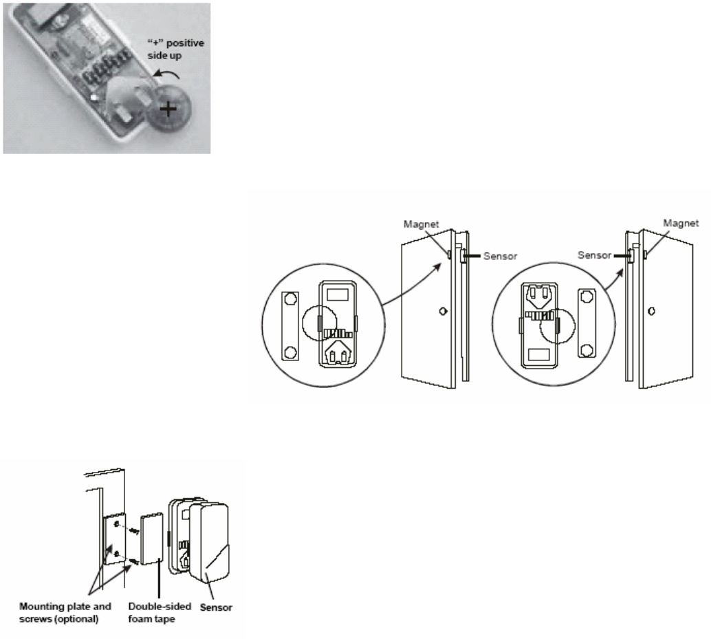
Installing the Door/Window Sensor
Window / Door Sensor is used to monitor doors or windows that open and close. When these
doors / windows are open or closed, the sensors will transmit a signal to the control panel to
notify the user. These sensors consist of 2 parts, one is the transmitter, the other is the magnet.
Remove the top cover of the sensor and insert the 3V lithium
battery to the sensor.
The transmitters should be
mounted on the door frame or
window frame by double sided
tape. The magnet should be
mounted on the door or window
by either double sided tape or
screws.
Make sure the arrow on the
magnet is aligned with the grey
marking on the transmitter.
(Show picture)
If the surface of the frame is flat enough, double-sided foam
tape is sufficient, otherwise, it is recommended to use the
mounting plate and screws as well. After mounting the
sensor, put the cover back on with the Houselink logo in the
upright position.
Try to mount the sensors as far away from the floor as possible to avoid damaging them.
Mounting the sensors at a higher position will also result in better operating range.
Do not mount the sensor to the exterior of the door / window, always mount the sensor to the
interior side of the door / window to avoid being damaged or stolen by non-intended users.
Testing: Open the door or window to trigger the sensor, the main unit will then alert you by
visual/audio indication and voice cue.
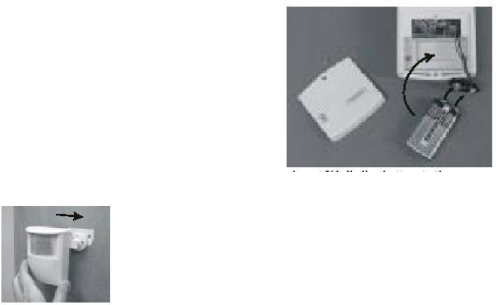
Installing the Motion Sensor
The motion sensor is most suitable for guarding the bedrooms. Use the motion sensor to
monitor the passage leading to the bedrooms or hallway.
You needed to power up the sensor first. Undo the
screw on the back of the motion sensor and remove
the cover of the battery compartment. Connect a
9V alkaline battery to the connector wire.
If you are going to install the motion sensor outdoor,
please change the sensitivity to low by changing the
sensitivity jumper from HI to LOW. You also needed
to change that zone to an Alert Zone. (Refer to p.
XX)
Then close the battery cover and re-insert the screw.
Mount the ball-head joint on the wall with screws provided. Slide the
back of the sensor into the ball-head joint. The mounting angle can be
adjusted.
Keep sensors within 30m (100 ft) of Control Panel.
Walk in the detected area. If the motion is detected, a read light inside the sensor will glow. If
the red light does not glow, motion has not been detected and you should re-position the sensor.
Repeated this procedure until your motion is detected. There should be no movement in the
detected area during the 20 seconds.
Note: When installing the motion sensor, avoid placing it near heat or cold producing devices
(i.e. A/C or furnace vents, fans, ovens, space heaters, etc). Air movement, especially caused by
changes in temperature may trigger the Motion Sensor and cause false alarms. Please
carefully test your Motion Sensor so that it will only be triggered by people.
Battery notes for the System
When you are reminded by the system that any sensors are in low battery, please change the
battery accordingly. The sensors, keychain remotes and accessories are generally designed to
have a battery life of around one year. Since there are large variations in different working
environment, we suggest replace new batteries every nine months.
The alkaline batteries in the main unit are expected to use as back up purpose in normal
working condition. We suggest you replace the alkaline batteries every nine months after you
have installed new batteries or right after a shortage of electricity in your premises.

Alarm & Alert Mode
Mode ARM LED When a sensor
Triggered
Application
Alert Off Notify by voice
announcement, beeping
and LED flashing.
When somebody in the home. The
system alerts you what is
happening around the users.
Arm On Siren goes off, LED
flashing and voice
announcement. Built-in
dialer calls for help.
When nobody in the home. The
system calls for help when a sensor
is triggered.
Alert mode
In Alert mode, the control panel will give you notification of the triggered sensor(s) by voice
announcement, unique beeping and LED flashing.
Number of beeps of Buzzer = Zone of the triggered sensor
Number of flashes of LED = Sensor number of the triggered sensor
Voice announcement = Tells you the zone and locations of the triggered sensor by human voice.
If zone 1 sensor 1 is triggered, you will hear a voice announcement “Zone 1 Sensor 1 triggered”
from the control panel. It will also emit one beep at a time, and the LED will flash once at a time.
If zone 3 sensor 2 is triggered, you will hear “Zone 3 Sensor 2 triggered. It will also emit 3
beeps at a time, and the LED will flash twice at a time.
Note: Each zone can program up to 2 sensors. There are 5 zones, so up to 10 sensors can be
programmed to the control panel.
For Door / Window sensor, alert notification (beeping and LED flashing) will continue until the
sensor is in the closed position, i.e. closing that window or door.
For Motion Detector, the alert notification (beeping and LED flashing) will last for 15 seconds for
every detected movement.
Mute
When the beeping becomes undesired, you can terminate the beeping in 3 different ways:
1) Manual mute by pressing the mute button
Pressing the mute button will terminate the beeping for all the activated sensors. For example,
if a window with a window sensor will be open for a long period of time, the continuous beeping
may become undesired. Pressing the mute button will temporary disable the beeping for this
sensor only, while it will still beep if other sensors are triggered. When the muted sensor is
closed and triggered again, the beeping will resume, i.e. if the window is closed and then re-
open, beeping will continue.
2) Change the buzzer mode to Alarm only
The beeping can be disabled for all zones and all times by changing the buzzer mode selector
(on the right side of the panel) to Alarm only. All sensor alert beeping will be ignored, while the
alarm siren will sound.
3) Enable Auto-Mute in Advanced Programming
This is to terminate the beeping for the specific zone(s) after it’s been beeped for 15 seconds.
That means beeping will be terminated automatically after 15 seconds if this feature is enabled
for that zone. Refer to Advanced Programming for more information on how to enable this
feature.
System Status
The control panel continuously monitors the system status as well as all the sensors status. It
will monitor which sensors are triggered, any low battery sensors, any mal-function sensors, or
a phone line failure.
In order to check the system status, user can press the “Status” button on the control panel,
voice announcement will be made regarding the system and sensor status. When the “Status”
button is pressed, you will be notified if any of the following events is occurring:
- System armed of disarmed
- Any triggered sensors
- Any sensors with low battery warning
- Any sensors with failure warning
- Phone line failure
Arm Mode
Arming the System
You should arm the system when you are the last person to leave the house. By arming the
system, the control panel will call the preprogrammed emergency phone numbers and siren will
sound when break-in occurs.
Note: Only arm the system when nobody is expected to be inside the premises. When
someone is expected to be within the premises, the system should not be armed.
To arm the system, follow the procedures below:
1. Press “Arm” button on the control panel when no sensors are triggered. You can also use
the keychain remote to arm the system by pressing button 1 on the remote.
Note:
• The control panel cannot be armed if there are triggered sensors. Make sure all
sensors are in closed position, i.e. (close all doors, windows, no movement should be
detected etc).
• The control panel can be armed if there are sensors with low battery or failure warning.
2. After pressing the “ARM” button, the “ARM” LED will flash and you will have 45 seconds to
leave the premises, this is called the exit delay. You will hear beeping during the exit delay
interval. The beeping rate will change from slow to fast, the faster the beep rate, the less
time you have left to leave the premises before the siren sounds.
3. When the exit delay expires, you will hear “System Armed” and beeping will stop and the
ARM LED will be on steadily. This indicates the system is now armed.
Note: The control panel can also be armed even nobody is home, with a touch tone phone.
Please refer to “Remote Operation by Telephone”
Disarming the system
If you trigger a sensor when entering a house with an armed control panel, you will trigger the
entry delay. You will have 30 seconds to disarm the control panel. Otherwise, the siren will
sound and emergency calls will be made. To disarm the control panel, follow the instructions
below.
1. If any sensors are now triggered when the control panel is armed, the system will beep for
30 seconds, and ARM LED will flash during this entry delay interval. The faster the beep,
the less time you have left to disarm the control panel before the siren sounds.
2. You must enter a valid password (either the Master Password, or Secondary Password) in
order to disarm the system before the entry delay expires. The system can also be
disarmed by pressing button 3 on the keychain remote.
3. When a valid password is entered, you will hear “System Disarmed” and the entry delay
beeping will stop, the ARM LED will be off.
Note:
• The control panel can also be armed even nobody is home, with a touch tone phone.
Please refer to “Remote Operation by Telephone”.
• If 3 consecutive incorrect passwords are entered, alarm will sound immediately and the
control panel will be in panic mode, and start calling the emergency phone numbers.
Disarming a triggered control panel
If you hear the announcement from the control panel “System Panic” after disarming the system,
that means at least one sensor was activated which caused the alarm to sound while you were
away. Following the procedures below to set the control panel back to standby mode.
1. There will be flashing LEDs indicating the sensor(s) that triggered the alarm. You may want
to check the condition of the triggered sensor(s), the sensor(s) may be damaged if there
were break-ins.
2. You need to reset the sensor by manually triggering it twice, i.e. open and close a door /
window sensor, or walk in front of the motion sensor. The LED representing that sensor will
then stop flashing.
3. You must now enter the password again on the control panel or press the button 3 of the
keychain remote, as an acknowledgement of the alarm event. This will set the control panel
back to standby mode.
Note: The control panel can also be disarmed even nobody is home, with a touch tone phone.
Please refer to “Remote Operation by Telephone”
Disarming under Duress
If you are forcibly compelled to disarm the control panel, you may enter the Duress Password.
Entering the duress password will stop the siren from sounding but the control panel will silently
call the emergency phone numbers for help. The called party will hear the voice announcement
“System Panic”.
Panic
Pressing the panic button will cause the siren to sound and outgoing calls will be made to the
preprogrammed phone numbers, “System Panic” will also be announced. This can be used in
any emergency situation. You can also press the panic button on the keychain remote to
perform the same function.
To stop the siren, user can enter either the Master Password, or the Secondary Password. You
can also press button 3 on the keychain remote to perform the same function. This will
terminate both the siren and the control panel from calling the rest of the emergency phone
numbers.
Receiving an emergency call
f you are on the list as one of the recipients of the emergeIncy call, you should read the
ey
1. r a
3.
re, entering the valid password is a
ay to acknowledge the emergency message. The control panel will continue to call the rest of
e phone numbers, unless the control panel is disarmed.
following instructions carefully. You should also notify all the persons you will be calling so th
know how to react when they receive the emergency call.
The control panel will call you when there are emergencies such as break-ins, smoke or fire
events, or a senior at home needs assistance.
When the phone rings at the calling location, the person who answers the phone will hea
message related to the emergency events, such as “System Panic”, or “Zone 1 Sensor 1
Triggered” etc. This message may be repeated several times depending on how it was
programmed.
2. After the message has been played for the certain number of times, the control panel will
ask for a valid password, you will hear “Enter Password”.
Enter the 4-digit password in order to have access to the control panel, such as to disarm
the alarm so it will stop the siren from sounding and terminate it from calling the rest of the
numbers. If a valid password is accepted, you will hear “Password Accepted”, otherwise,
you will hear “Password Failure”.
4. After entering the correct password, you can follow the “Phone Command” instructions to
perform the required tasks, such as disarm, check the system status again etc.
Note: Once the called party has entered a valid password, that person will not be called again,
ven the redial count is set to call more than once. Therefoe
w
th
Home Automation
By adding the optional Skylink receivers, such as the Light Switch Receiver Model SW-100R,
the control panel can be used to control up to 5 different receivers. There are 3 ways to control
these receivers:
1. Using the keypad on the control panel to operate these receivers manually
2. Calling in away from home using a touch tone phone (Refer to “Remote Operation by
Telephone”)
3. Setting up Event Trigger (Refer to Advanced Programming)
These receivers should be programmed to the control panel as device 1 to 5. Please follow the
programming instruction for additional devices for further information.
Light Switch Receiver Model SW-100R
To turn off a light with the control panel:
1. Press the device number button on the control panel, i.e. pressing 1 will turn off device 1,
pressing 2 will turn off device 2.
2. You will hear “Device X Off”, where X is the device number.
3. You will also see the PROG LED flashes, that indicate the control panel is sending out the
wireless signal to control the specific device.
4. If the receiver receives the signal, the control panel will announce “ Device Off Accepted”.
To turn on a light with the control panel:
1. Press the number below the device number that you would like to turn on, i.e. pressing 6 will
turn on device 1, pressing 7 will turn on device 2.
2. You will hear “Device X On”, where X is the device number.
3. You will also see the PROG LED flashes, that indicate the control panel is sending out the
wireless signal to control the specific device.
4. If the receiver receives the signal, the control panel will announce “Device On Accepted”.
Communication
Remote Operation by Telephone
The control panel can be operated while you are away from home. You can have access to the
control panel with any touch tone phone to perform a variety of operations, listed below.
• Arm
• Disarm
• Lights on / off
• Garage door open / close
• System status
• Disconnect
tion.
2. uring emergency, you can enter a valid password to have
access to the remote operations.
There are 2 ways you can have access to the remote phone opera
1. You can call the control panel when you are away from home;
When the control panel calls you d

To access the control panel away from home
1. Call your home phone number, or the number that the control panel is connected to.
Hang u2. p after hearing the second ring.
4. need to enter
hear “Password Accepted”, otherwise, you will hear “Password Failure”.
ou can have access to all the operations listed below:
able 1: Remote Phone Operations
rgency phone
umbers, the called party will hear the emergency message, it will then ask for a password. If a
valid password is entered, the operations listed in Table 1 will be available.
ds, including
ow the program additional sensors, remotes, how the buzzer behaves for different zones,
The follow advanced programming fields.
Options Com
3. Wait at least 10 seconds, but not more than 1 minute, then call your home phone number
again.
The control panel will pick up the phone call and ask for a password. You
either the Master Password or Secondary Password. If the password is correct, you will
5. Once the password is accepted, y
T
System Operation Phone
Command Description
Turn on device X X + [#]
on, will hear
Turn lights
confirmation, “Device On
Accepted”
Turn off device X X + [*]
Turn lights off, will hear
f confirmation, “Device Of
Accepted”
Check system status [8] + [#] Will hear system status
announcement
Arm [7] + [#] Will hear “System Armed”
Disarm [9] + [#] Will hear “System Disar
med”
The same operations can be performed when the control panel calls the eme
Disconnect [0] + [#] Phone line disconnect
n
Advanced Programming
You can customized the control panel in different configurations to suit your nee
h
event trigger setting etc.
ings are the
Programming mand
Learn Sensor [PROG] + [3]
Learn Remote or Receiver [PROG] + [4]
Beep / Alarm [PROG] + [5]
Auto Mute [PROG] + [6]
Event Trigger [PROG] + [7]

Alert Zone [PROG] + [8]
Erase Sensor [PROG] + [9]
Erase Remote / Receiver [PROG] + [0]
Learn Sensor
t trigger,
xplanation for each zone dependent feature can be found in Advanced
rogramming.
ensor Location Selection Guide
bled. It is not possible to enable a zone dependent feature for sensor 1 only, but
ne
2.
3.
able
es.
Detailed explanation for each feature can be found in Advanced Programming.
en
You can program up to 10 sensors to the control panel. There are 5 zones, each zone can
program 2 sensors. Before programming a sensor, you must decide which sensor location
(zone number and sensor number) you would like to program the sensor to. It is strongly
recommended that you refer to “Sensor Location Selection Guide” and study the 4 zone
dependent features before deciding which sensor location you would like to program the new
sensors to. The 4 zone dependent features are: 1) buzzer sound, 2) auto mute, 3) even
) alert zone. E4
P
S
You can program up to 10 sensors to the control panel. There are 5 zones and there are some
zone dependent features. Zone dependent feature means all the sensors in that zone will
operate based on the setting for that zone. So if you program 2 sensors into one zone, those 2
sensors will react in the same manner for those zone dependent features. For example, if you
enable the Auto-Mute feature for zone 1, both zone 1 sensor 1, and zone 1 sensor 2 will have
his feature enat
not sensor 2.
Therefore, the followings are some suggestions of how you should select the sensor location.
1. Check all the zone dependent features, and determine if you would like to enable any o
of them.
If you decide not to enable any zone dependent features and keep the factory default
setting, you can simply program the sensor to any sensor location based on your own
preference. Omit the following steps.
If you decide to enable some of the zone dependent features, check Table 2 below. Circle
the zone dependent feature selections. If there are features that you would like to en
for more than 2 sensors, you need to select more than one zone for those featur
Sensor 1 Sensor 2 Zone Depend t Features
Location Location Auto Mute Beep / Alarm Event Trigger Alert
Zone 1 Beep / Alarm Y / N Disabled / On / Off Y / N
Zone 2 Beep / Alarm Y / N Disabled / On / Off Y / N
Zone 3 Beep / Alarm Y / N Disabled / On / Off Y / N
Zone 4 Beep / Alarm Y / N Disabled / On / Off Y / N
Zone 5 Beep / Alarm Y / N Disabled / On / Off Y / N

4. Once you have filled out the table, it should look something like this.
enSensor 1 Sensor 2 Zone Depend t Features
Auto Mute
Location Beep / Alarm Event Trigger Alert Location
Zone 1 Front Door Front Window Beep / Alarm Y / N Disabled / On / Off Y / N
Zone 2 Kitchen Motion Beep / Alarm Y / N Disabled / On / Off Y / N
Zone 3 Back Door Y / N
Beep / Alarm Disabled / On / Off Y / N
Zone 4 Backyard Motion Beep / Alarm Y / N Disabled / On / Off Y / N
Zone 5 Basement Water Motion Beep / Alarm Y / N Disabled / On / Off Y / N
Basement
You can now refer to each column representing the zone dependent features, to program
each zone with the selected feature. For example, Auto Mute feature is only enabled for
zone 3, when you are in the auto mute programming, you should set it so that auto mute is
only enabled for zone 3, the rest of the zone should hav
5.
e this feature disabled. Repeat this
step for all 4 zone dependent features programming.
earn Sensor – continue
r to
e control panel. To learn a sensor into the control panel, follow the instructions below.
6. sword is
e emitted and [PROG] LED will be off.
8. once, some of
or.
9.
1 for
ee Fig. X. After
selecting the zone and sensor numbers, that zone LED will be on.
L
After studying the “Sensor Location Selection Guide”, you may proceed to learn the senso
th
5. Press the [PROG] button on the side of the control panel, the [PROG] LED will be on.
Enter the current Master Password. Control panel will emit 3 beeps if the valid pas
entered, otherwise a single long beep will b
7. Enter [3], which represents “learn sensor”.
Notice all 5 zone LEDs, some of them may be off, some of them may flash
the may flash twice. The LED flashing represents the occupied sensors.
• If the zone LED remains off, that indicates that zone is not occupied by any sens
• If the zone LED flashes once, that indicates sensor 1 of that zone is occupied.
• If the zone LED flashes twice, that indicates sensor 2 of that zone is occupied.
You may now select a zone and sensor location to program the sensor to. Select the zone
and sensor number by pressing on to button 1 to 0. Buttons 1 to 5 represent sensor
zones 1 to 5. Buttons 6 to 0 represent sensor 2 for zones 1 to 5. S
Sensor 1 Sensor 2
Zone 1 Button [1] Button [6]
Zone 2 Button [2] Button [7]
Zone 3 Button [3] Button [8]
Zone 4 Button [4] Button [9]
Zone 5 Button [5] Button [0]

10. Activate the sensor, the control panel will beep and you will hear “Zone _ Sensor _
Accepted” if the sensor is programmed, the [PROG] LED will be off. To program another
sensor, repeat the above steps.
ote: If an occupied sensor location is selected, the new sensor will replace the old one.
dditional keychain or keypad remote can be programmed to the control. You may also
odel SW-100R or Garage
programmed
the control panel.
Receivers should be programmed to Device 1 to Device 5.
ll
1.
2. panel will emit 3 beeps if the valid password is
ente ,
3. Enter [4] arn Keychain / Receiver”. Notice all 5 zone LEDs, some of
them a
flashing
N
Learn Remote / Receiver
A
program additional receivers such as the Light Switch Receiver, M
Door Receiver GD-101R. Maximum of 5 keychain remotes and 5 receivers can be
to
•
• Keychain or keypad remote should be programmed to Device 6 to Device 0.
ow the instructions below to program remotes / receivers. Fo
Press the [PROG] button on the side of the control panel, the [PROG] LED will be on.
Enter the current Master Password. Control
red otherwise a single long beep will be emitted and [PROG] LED will be off.
, which represents “Le
m y be off, some of them may flash once, some of the may flash twice. The LED
represents the occupied sensors.
• If the zone LED remains off, that indicates that zone is not occupied by any
keychain / receiver.
• If the zone LED flashes once, that indicates a receiver has occupied that device.
Zone 1 LED flashes once means Device 1 is occupied.
• If the zone LED flashes twice, that indicates a keychain / keypad remote has
occupied that zone. Zone 1 LED flashes twice means Device 6 is occupied.
For programming a receiver, select a device number from Device 1 to Device 5. Press and 4.
ce on
5.
selected, that zone LED will be on steadily. You
can now transmit a signal by pressing one of the buttons from the keychain.
. The control panel will beep and you will hear “Device X Accepted” if the device is
programmed and the [PROG] LED will be off. To program another remote / receiver, repeat
hold the learn button on the receiver continuously, you will see the LED flashing rapidly. To
select device 1, press button 6. The LED stop flashing indicate the receiver has received
the signal. Then press button 1 on control panel for device 1. Once a device is selected,
that zone LED will be on steadily. . You can now transmit a signal by pressing on
learn button on the receiver.
For programming a keychain, select a device number from Device 6 to Device 0. To select
device 6, press button 6. Once a device is
6
the above steps.
Note: If an occupied device is selected, the new sensor will replace the old one.

Zone Dependent Setting – Beep / Alarm
r can customize the audio warning so that when a sensor is triggered, it may bee
se
secu
• alarm
immediately, but it will stop when the sensor is back to normal (door closes). It
umbers since it is not armed.
without entry delay, it is called
tered.
l z the factory.
•
• or is not located outdoor
1. Pre th
2. Enter the current Master Password. Control panel will emit 3 beeps if the valid password is
3.
ents the current beep / alarm
setting.
• If the zone LED flashes, that ind the zon rammed to “Beep”.
• If the zone LED remains steadily on, that indicates the zone is programmed to
“Alarm”.
4. To change the setting between beep and alarm, press buttons 1 to 5 will set that zone to
beep. Pressing buttons 6 to 0 will set o ala to Fig X. After making the
change, notice the stat zone es a
Beep Alarm
Up, or an
alarm may sound immediately. Depending on whether the control panel is in alert mode or
rity mode, the audio warning will be different.
Alert mode: If a sensor is triggered (i.e. opening a door) with the alarm feature on, the
will sound
control panel will not call the emergency phone n
Security mode: If a sensor is triggered (i.e. opening a door) with the alarm feature on and •
the system is armed, the siren will sound immediately
“Instant Alarm”. The siren will not stop until the siren timeout or a valid password is en
Control panel will call the emergency phone numbers to notify the users of the alarm
situation.
l ones were programmed to beep at A
It is recommended to program a zone into Alarm mode if:
• You need immediate attention if that sensor is triggered, such as flood sensor, smoke
sensor etc.
The sensor will not be triggered on a daily basis
The sens
ss e [PROG] button on the side of the control panel, the [PROG] LED will be on.
entered, otherwise a single long beep will be emitted and [PROG] LED will be off.
Enter [5], which represents “Beep / Alarm” setting. Notice all 5 zone LEDs, some of them
may be off, some of them may flash. The LED flashing repres
icates e is prog
that zone t rm. Refer
us of the LED chang s well.
Zone 1 Button [1] Button [6]
Zone 2 Button [2] Button [7]
Zone 3 Button [3] Button [8]
Zone 4 Button [4] Button [9]
Zone 5 Button [5] Button [0]
5. You are allow to make unlimited changes before programming is quit. Once you are
satisfied with the settings, press [PROG] to quit programming and the settings will be saved.

Zone Dependent Setting – Auto Mute
Once a sensor is triggered, audio warning will be emitted, either beep or alarm. For example, if
n for
This fea re
1.
current Master Password. Control panel will emit 3 beeps if the valid password is
entered, otherwise a single long beep will be emitted and [PROG] LED will be off.
3. Enter [6], which represents “A ti ome of them may
be off, some of them may flash. The LED flashing represents the current auto mute setting.
• If the zone LED flashes, that indicates auto mute is disabled
• If the z remains s
4. To change the setting between au ble and disa buttons 1 to 5 will
disable auto mute for those zones buttons 6 to le auto mute for those
zones. Refer to Fig X. After maki notice the status of the zone LED changes
as well.
a door is opened, the audio warning will not stop until the door is closed. If the door is ope
2 hours, the audio warning will go on for 2 hours. There are times that this is not desired. With
the auto mute feature enabled, the audio warning will go on for only 15 seconds. After that, if
sensor remains open, only the zone LED will flash to indicate the sensor is triggerethe d. Audio
warning will go on again if the sensor is closed and open again.
tu was disabled for all zones at the factory.
To enable auto mute feature, follow the instructions below.
Press the [PROG] button on the side of the control panel, the [PROG] LED will be on.
Enter the 2.
uto Mute” setting. No ce all 5 zone LEDs, s
one LED teadily on, that indicates auto mute is enabled
to mute ena ble, press
. Pressing 0 will enab
ng the change,
Disable Auto Mute Enable Auto Mute
Zone 1 Button [1] Button [6]
Zone 2 Button [2] Button [7]
Zone 3 Button [3] Button [8]
Zone 4 Button [4] Button [9]
Zone 5 Button [5] Button [0]
5. You are allowed to make unlimited changes before programming is quit. Once you are
satisfied with the settings, press [PROG] to quit programming and the settings will be saved.
ically. It is called Event Trigger.
nel will transmit a signal to activate the
en the door sensor is open, turn the
s
Even , you
can program device 1 to be on or off when zone 1 sensor(s) is triggered. You can also program
device 2 to be on / off when zone 2 sensor(s) is triggered.
Zone Dependent Setting – Event Trigger
Home Automation is one of the features that makes this system so powerful. You can control
p to 5 different devices not only manually, but also automatu
That means when a sensor is triggered, the control pa
esignated receiver. Applications include: d
• Lights on when you open the front door (wh
lighting receiver on)
• Lights on when you walk into the kitchen (when the motion sensor in the kitchen i
activated, turn the lighting receiver on)
t trigger is only applicable to the sensors and receiver in the same zone. For example

feature was disabled for all zones at the factory. This
To en le
1. Press e [PROG] LED will be on.
2.
is en D will be off.
ab event trigger, follow the instructions below.
the [PROG] button on the side of the control panel, th
Enter the current Master Password. Control panel will emit 3 beeps if the valid password
tered, otherwise a single long beep will be emitted and [PROG] LE
3. Enter [7], which represents “Event Trigger” setting. Notice all 5 zone LEDs, some of them
may be off, some of them may flash once, some of them may be on steadily. The LED
flashing represents the current event trigger setting.
• If the zone LED is off, that indicates event trigger is disabled.
• If the zone LED flashes, that indicates event trigger is enabled, and it will turn off the
corresponding device when the sensor(s) is activated
• If the zone LED remains steadily on, that indicates event trigger is enabled, and
turn
it will
on the corresponding device when the sensor(s) is activated
. To change the event trigger setting, press buttons 1 to 5 will d
zones. P ssing buttons 6 event trigger for those zones. However, even
this feature is enabled, you still have to select whether you want to turn that device on or
off when the sensor(s) is trig ssing buttons [6] to [0] will toggle the setting
between on and off. For exa LED is currently vent trigger for zone 2
is enable with the Off signal, you can press button [7] to change it to the On signal.
Pressing [7] again will change it back to Off signal. Refer to Fig X. After making the
change, notice the status of the zone LED changes as w
Disable Event
Trigger Enable Event Trigger
(Toggle between Off
4isable event trigger for those
re to 0 will enable
gered. Pre
mple, if the showing e
ell.
and On)
Zone 1 Button [1] Button [6]
Zone 2 Button [2] Button [7]
Zone 3 Button [3] Button [8]
Zone 4 Button [4] Button [9]
Zone 5 Button [5] Button [0]
5. You are allowed to make unlimited changes before programming is quit. Once you are
satisfied with the settings, press [PROG] to quit programming and the settings will be
ote: If event triggered is enabled for a door sensor, which turn lights on when it is open, this
ave
n operate in 2 different modes, 1) Alert Mode, 2)
nd immediately (with instant
not want to trigger the alarm when the system
saved.
N
feature will not be activated during exit delay. Since during exit delay, users suppose to le
the premises and therefore lights will not be turned on. However, if the event triggered is
enabled to turn lights off, it will be activated during exit delay.
Zone Dependent Setting – Alert Zone
As explained earlier, the control panel ca
Security Mode. In security mode, when a sensor is triggered, the control panel will need to be
disarmed either after 30 seconds (with entry delay), or siren will sou
alarm). However, there are sensors that you do

is armed. Such as outdoor motion sensor, or any other sensors that you only want to give you
lert notification. Under such circumstances, zone(s) can be program to react only when the
red when the control panel is in security
ode.
is recommend to enable alert zone if:
This
To enabl le
2.
. lert Zone” setting. Notice all 5 zone LEDs, some of them
may be off, so e of them m sh urrent alert zone
setting.
• If the flashes, s alert zone
• If the zone LED remains steadily on, that indicates alert zone is enabled
4. To change the setting between alert zone enable and disable, press buttons 1 to 5 will
disable alert zone feature for those zones. Pressing buttons 6 to 0 will enable alert zone
feature for those zones. Refer to r making th otice the status of the
zone LED cha well.
a
control panel is in alert mode, these zones will be igno
m
It
• You do not consider the sensors in that zone are emergency
• Sensors in that zone are located outdoor
• When nobody is home, you do not want to know the status of the sensors in that zone
feature was disabled for all zones at the factory.
e a rt zone feature, follow the instructions below.
1. Press the [PROG] button on the side of the control panel, the [PROG] LED will be on.
Enter the current Master Password. Control panel will emit 3 beeps if the valid password
is entered, otherwise a single long beep will be emitted and [PROG] LED will be off.
Enter [8], which represents “A3
m ay flash. The LED fla ing represents the c
zone LED that indicate is disabled
Fig X. Afte e change, n
nges as
Disable Alert Zone Enable Alert Zone
Zone 1 Button [1] Button [6]
Zone 2 Button [2] Button [7]
Zone 3 Button [3] Button [8]
Zone 4 Button [4] Button [9]
Zone 5 Button [5] Button [0]
. You are allowed to make unlimited ch5 anges before programming is quit. Once you are
Procee the
3.
4. f
satisfied with the settings, press [PROG] to quit programming and the settings will be
saved.
Erase Sensor
d followings to erase a sensor.
1. Press the [PROG] button on the side of the control panel, the [PROG] LED will be on.
2. Enter the current Master Password. Control panel will emit 3 beeps if the valid password
is entered, otherwise a single long beep will be emitted and [PROG] LED will be off.
Enter [9], which represents “Erase Sensor”.
Notice all 5 zone LEDs, some of them may be off, some of them may flash once, some o
the may flash twice. The LED flashing represents the occupied sensors.

• If the zone LED remains off, that indicates that zone is not occupied by any sensor.
• If the zone LED flashes once, that indicates sensor 1 of that zone is occupied.
• If the zone LED flashes twice, that indicates sensor 2 of that zone is occupied.
5. You may now select which sensor lo ase zone and sensor number
by pressing buttons [1 utton prese
6 to 0 represent sens ones r sel ensor location, you will
hear 3 beeps and “Zone_ Sensor_ E ory”. rms the selected sensor
has been erased, and OG] L ff. To erase another sensor, repeat the
above steps.
Sensor 1 Sensor 2
cation to er . Select the
] to [0]. B s 1 to 5 re
1 to 5. Afte
nt sensor 1 for zones 1 to 5. Buttons
ecting the sor 2 for z
mpty Mem This confi
the [PR ED will be o
Zone 1 Button [1] Button [6]
Zone 2 Button [2] Button [7]
Zone 3 Button [3] Button [8]
Zone 4 Button [4] Button [9]
Zone 5 Button [5] Button [0]
e Remotes / Receiver E
ras
Follow the instructions below to erase keychain or keypad remotes / receivers.
1. Press the [PROG] button on the side of the control panel, the [PROG] LED will be on.
2. Enter the current Master Password. Control panel will emit 3 beeps if the valid password
is entered, otherwise a single long beep will be emitted and [PROG] LED will be off.
3. Enter [0], which represents “Erase Keychain / Receiver”. Notice all 5 zone LEDs, some of
them may be off, some of them may flash once, some of the may flash twice. The LED
flashing represents the occupied sensors.
• If the zone LED remains off, that indicates that zone is not occupied by any keychain /
receiver.
• If the zone LED flashes once, that indicates a receiver has occupied that device. Zone 1
LED flashes once means Device 1 is occupied.
• If the zone LED flashes twice, that indicates a keychain / keypad remote has occupied that
zone. Zone 1 LED flashes twice means Device 6 is occupied.
4. To erase a receiver, enter a device number from Device 1 to Device 5. To select device 1,
press button 1. Once a device is selected, you will hear 3 beeps and “Device_ Empty
Memory”.
5. To erase a keychain, enter a device number from Device 6 to Device 0. To select device 6,
press button 6. Once a device is selected, you will hear 3 beeps and “Device_ Empty
Memory”.
6. To erase another remote / receiver, repeat the above steps.
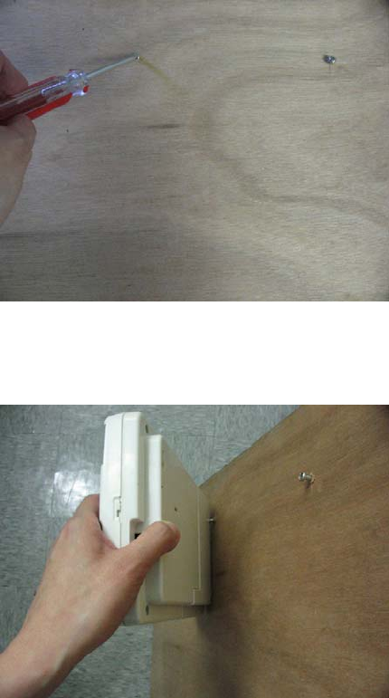
Mounting the Control Panel on the wall
1. Place the screw at the desired location.
2. Mount the unit onto the wall with 2 screws.

FCC Information
Consumer Information:
a) This equipment complies with Part 68 of the FCC rules and the requirements adopted by the
ACTA. On the bottom of this equipment is a label that contains, among other information, a
product identifier in the format US:AAAEQ##TXXXX. If requested, this number must be
provided to the telephone company.
b) An applicable certification jacks Universal Service Order Codes (USOC) for the equipment is
provided (i.e., RJ11C) in the packaging with each piece of approved terminal equipment.
c) A plug and jack used to connect this equipment to the premises wiring and telephone
network must comply with the applicable FCC Part 68 rules and requirements adopted by
the ACTA. A compliant telephone cord and modular plug is provided with this product. It is
designed to be connected to a compatible modular jack that is also compliant. See
installation instructions for details.
d) The REN is used to determine the number of devices that may be connected to a telephone
line. Excessive RENs on a telephone line may result in the devices not ringing in response
to an incoming call. In most but not all areas, the sum of RENs should not exceed five (5.0).
To be certain of the number of devices that may be connected to a line, as determined by
the total RENs, contact the local telephone company. [For products approved after July 23,
2001, the REN for this product is part of the product identifier that has the format
US:AAAEQ##TXXXX. The digits represented by ## are the REN without a decimal point
(e.g., 03 is a REN of 0.3). For earlier products, the REN is separately shown on the label.]
e) If this equipment
AM-002 causes harm to the telephone network, the telephone company will
notify you in advance that temporary discontinuance of service may be required. But if
advance notice isn't practical, the telephone company will notify the customer as soon as
possible. Also, you will be advised of your right to file a complaint with the FCC if you believe
it is necessary.
f) The telephone company may make changes in its facilities, equipment, operations or
procedures that could affect the operation of the equipment. If this happens the telephone
company will provide advance notice in order for you to make necessary modifications to
maintain uninterrupted service.
g) Should you experience trouble with this equipment, please contact Skylink Customer
Support at 1-800-304-1187 for repair or warranty information. If the equipment is causing
harm to the telephone network, the telephone company may request that you disconnect the
equipment until the problem is resolved.
h) Please follow instructions for repairing if any (e.g. battery replacement section); otherwise do
not alternate or repair any parts of device except specified.
i) Connection to party line service is subject to state tariffs. Contact the state public utility
commission, public service commission or corporation commission for information.
j) NOTICE: If your home has specially wired alarm equipment connected to the telephone line,
ensure the installation of this model AM-002 does not disable your alarm equipment. If you
have questions about what will disable alarm equipment, consult your telephone company or
a qualified installer.
NOTICE: According to telephone company reports, AC electrical surges, typically resulting from
lightning strikes, are very destructive to telephone equipment connected to AC power sources.
To minimize damage from these types of surges, a surge arrestor is recommended.
FCC STATEMENT
This device complies with Part 15 of the FCC Rules. Operation is subject to the following two
conditions: (1) This device may not cause harmful interference, and (2) This is device must
accept any interference received, including interference that may cause undesired operation.
Warning: Changes or modifications to this unit not expressly approved by the party responsible
for compliance could void the user’s authority to operate the equipment.
NOTE: This equipment has been tested and found to comply with the limits for a Class B digital
device, pursuant to Part 15 of the FCC Rules. These limits are designed to provide reasonable
protection against harmful interference in a residential installation. This equipment generates,
uses and can radiate radio frequency energy and, if not installed and used in accordance with
the instructions, may cause harmful interference to radio communications.
However, there is no guarantee that interference will not occur in a particular installation. If this
equipment does cause harmful interference to radio or television reception, which can be
determined by turning the equipment off and on, the user is encouraged to try to correct the
interference by one or more of the following measures:
□ Reorient or relocate the receiving antenna.
□ Increase the separation between the equipment and receiver.
□ Connect the equipment into an outlet on a circuit different from that to which the receiver
is connected.
□ Consult the dealer or an experienced radio/TV technician for help.
Customer Service
17 Sheard Avenue,
Brampton,
Ontario,
L6Y 1J3
Canada
Toll Free 1-800-304-1187
AAA Plus™ Accessories
The AAA Plus™ receiver can work with up to 10 sensors and 5 remote controls. It can also
used to trigger unlimited number of Houselink® secondary alarm and emergency dialer.
Sensor
WD-101
Door/Window Sensor
FS-101
Water Sensor
GS-102
Garage Door Sensor (Europe)
GS-101
Garage Door Sensor (North America)
PS-101
Motion Sensor
* suitable for indoor and outdoor (alert
mode) use.
Remote Control & Panic
Button
4B-434
Keychain Remote
PT-434 Panic Transmitter

KP-434 Keypad Remote
Wireless Switch for
Automation
SW-100R Wireless Switch Receiver (North
America)
SW-100R (same model
number for US and
EU?)
Wireless Switch Receiver (Europe)
External devices
RP-434
Repeater
* extend the wireless operating range
between receiver and all other
accessories.
AS-101
Audio Alarm
* used as external alarm.
AD-433S / AD-433SE Emergency Dialer (North America /
Europe)
SDO Series of
Products
Swing Door Operator
Coming soon??
Please visit www.skylinkhome.com or contact us at support@skylinkhome.com for more
information of how to fully utilize your AAA Plus™ system.