Card Access ZGB20 Card Access Security Sensor Bridge V2 User Manual QSG ZGB INST20 FCCv3
Card Access Inc Card Access Security Sensor Bridge V2 QSG ZGB INST20 FCCv3
UserManual.wiki
>
Card Access
>
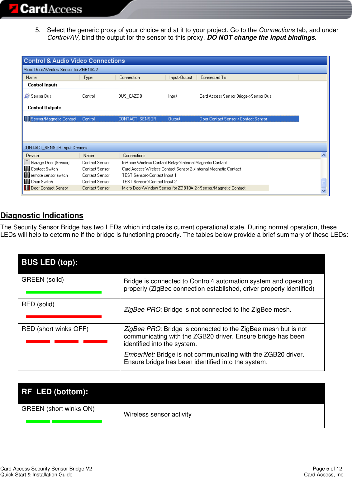
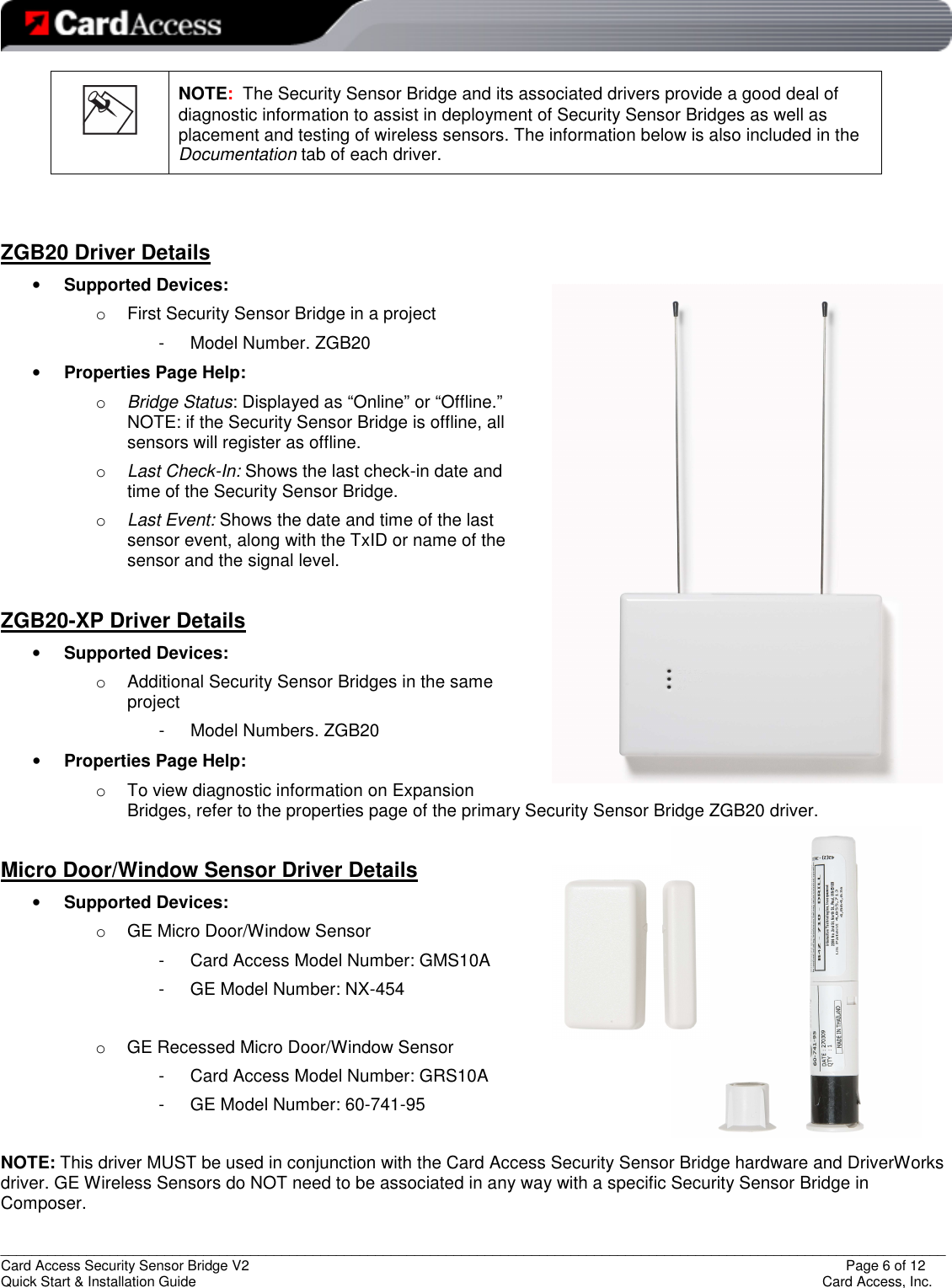
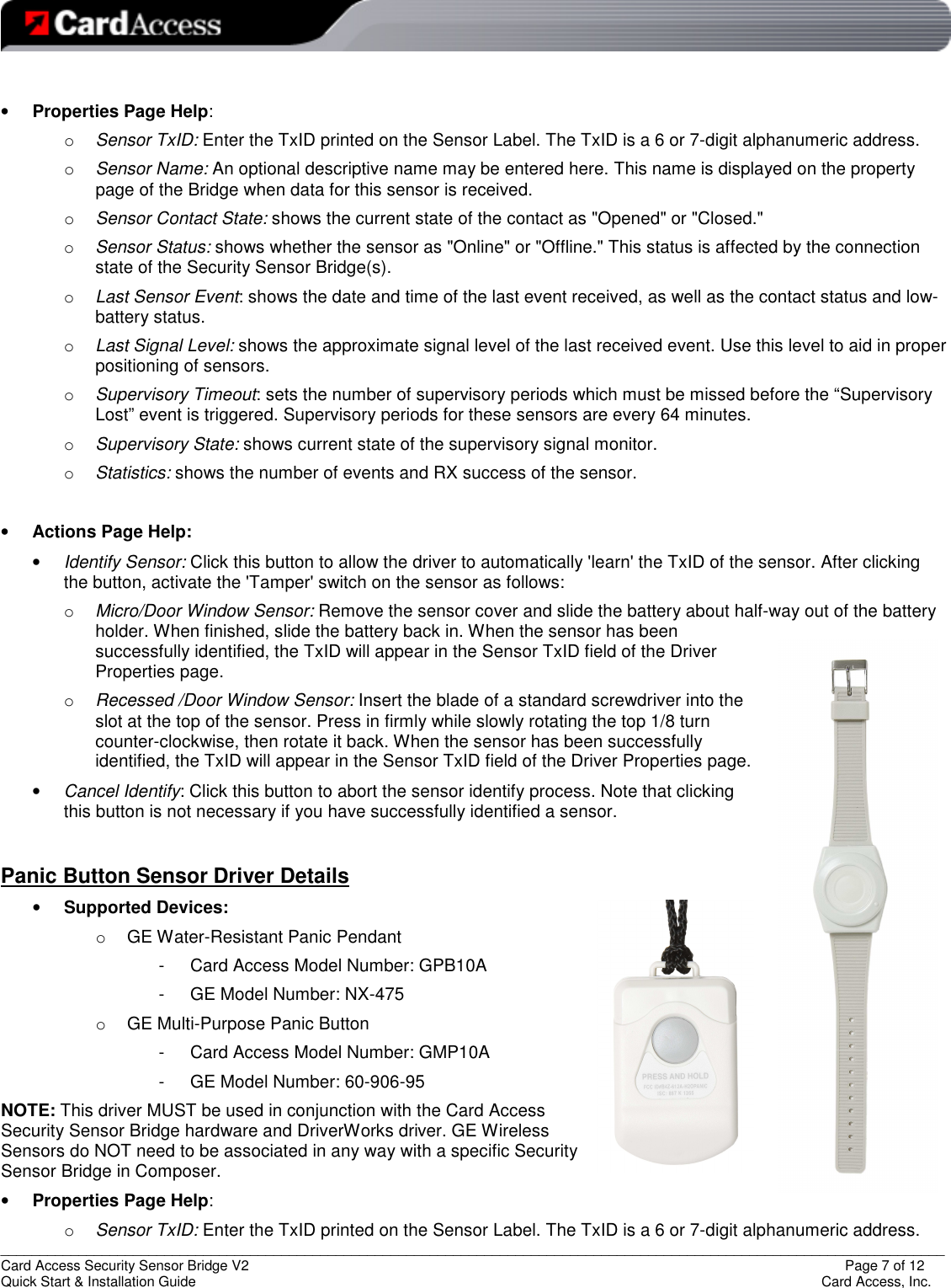
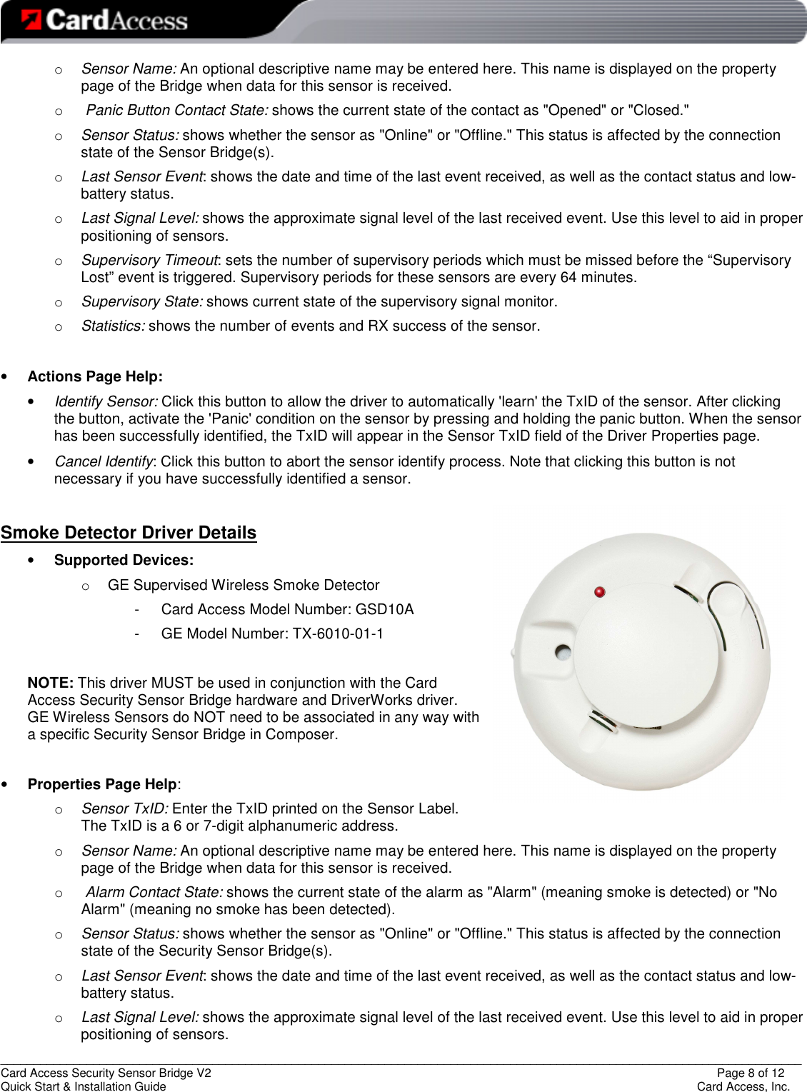
ZGB20 User Manual
User Manual
Navigation menu
Upload a User Manual
Namespaces
Wiki Guide
HTML
PDF
Info
Views
User Manual
Discussion / Help
Navigation