Card Access ZGB20 Card Access Security Sensor Bridge V2 User Manual QSG ZGB INST20 FCCv3
Card Access Inc Card Access Security Sensor Bridge V2 QSG ZGB INST20 FCCv3
User Manual

_________________________________________________________________________________________________________________________
Card Access Security Sensor Bridge V2 Page 1 of 12
Quick Start & Installation Guide Card Access, Inc.
Security Sensor Bridge V2
Model Number: ZGB20
Quick Start and Installation Guide
Card Access Security Sensor Bridge
Quick Start and Installation Guide
Easily bridge inexpensive security sensors into home automation -- with or without a security panel*
_________________________________________________________________________________________________________________________
Card Access Security Sensor Bridge V2 Page 2 of 12
Quick Start & Installation Guide Card Access, Inc.
Welcome and congratulations on your purchase of the Card Access Security Sensor Bridge. This Quick Start &
Installation Guide is an overview of configuring your Security Sensor Bridge with a Control4 System. This guide assumes
that you are a qualified and trained Control4 dealer.
*NOTICE: THE SECURITY SENSOR BRIDGE V2 IS INTENDED FOR HOME AUTOMATION PURPOSES ONLY. THIS
IS NOT A SECURITY SYSTEM.
Introduction
The Card Access Security Sensor Bridge is a device capable of receiving and interpreting signals from GE/ITI
sensors and integrating these signals with a Control4 System via the Control4 ZigBee wireless mesh. This device
gives the homeowner the ability to utilize the wide range of GE sensors available as accessories to the Control4
system.
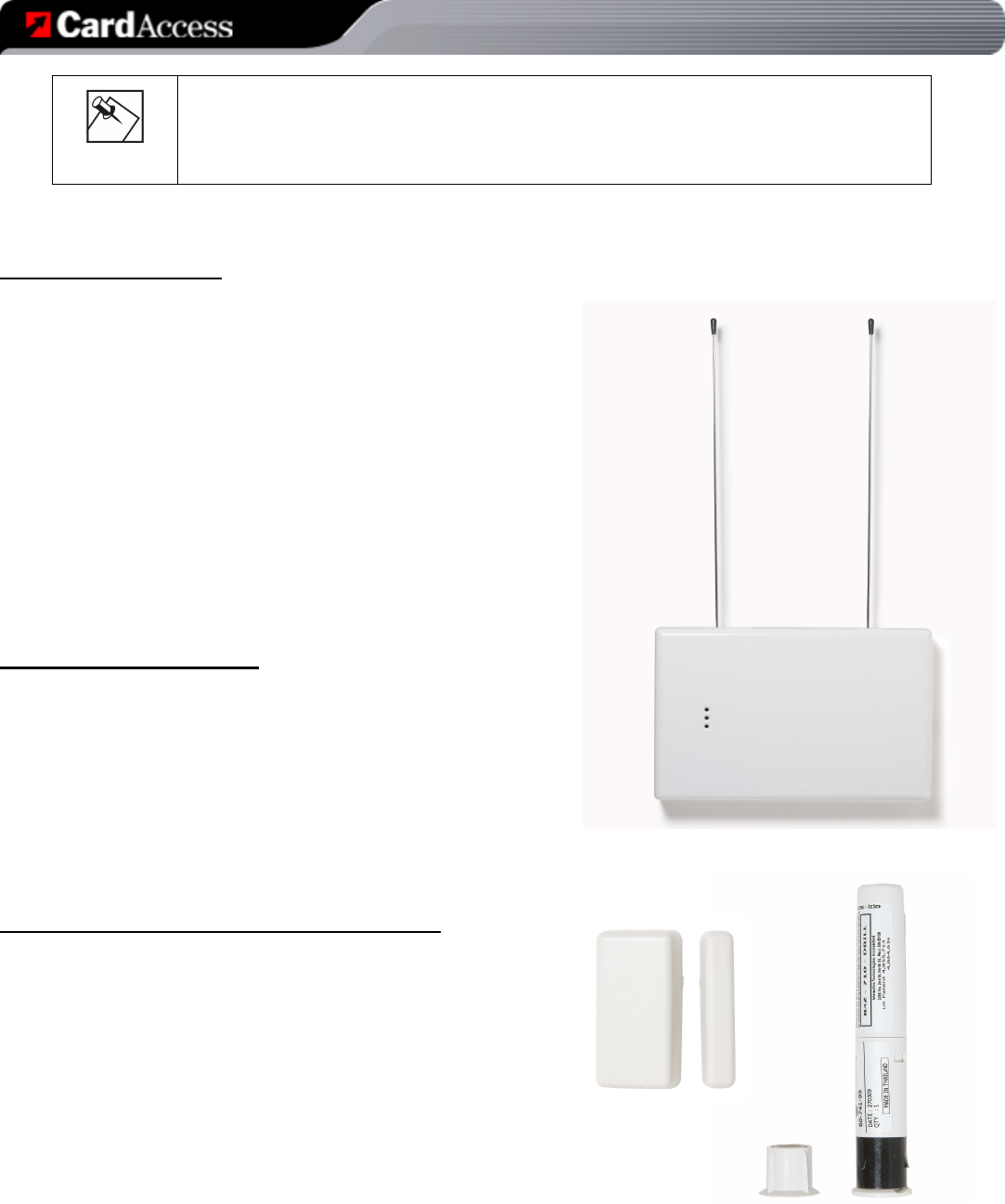
The device consists of a self-contained, wall-mountable bridge in a plastic enclosure. It is powered by a 12V DC
adapter.
Specifications
ZGB20 Specifications
Dimensions 6.75” x 4.5” x 1.5” (excluding antennas)
Weight 0.5 Lbs (0.23Kg)
Maximum Ambient Operational
Temperature 140°F (60°C)
Power Input 12VDC, 100mA
Operational Environment Type 1 Device shall be mounted in a dry, moisture-protected location.
Site Requirements and Wiring Options
•
Allow at least 10 inches of clearance above the enclosure for the antennas.
•
Avoid mounting locations that expose the module to moisture.
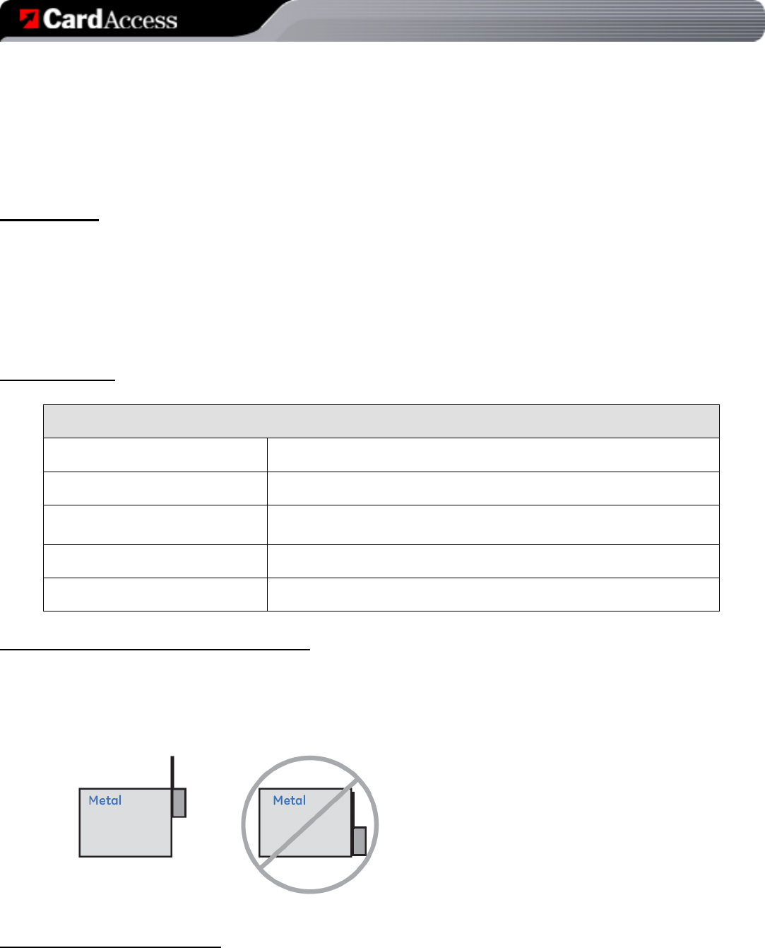
•
Avoid areas with excessive metal or electrical wiring including furnace and utility rooms. If unavoidable,
mount on or near metal with the antenna extending above the metallic surfaces as shown in Figure 1.
•
Ensure that an electrical source is accessible for the DC power adaptor.
Figure 1 - Mounting on or near metal
Tools and Supplies Needed
To complete the installation, you will need the following tools and supplies:
•
Screwdrivers
_________________________________________________________________________________________________________________________
Card Access Security Sensor Bridge V2 Page 3 of 12
Quick Start & Installation Guide Card Access, Inc.
•
Drill with bits
•
Mounting screws and anchors (included)
Mounting
The bridge can be mounted on any interior wall
(protected from the elements) by following these steps:
1.
Remove the cover by pressing in the button on
the bottom of the enclosure and rocking the
cover outward.
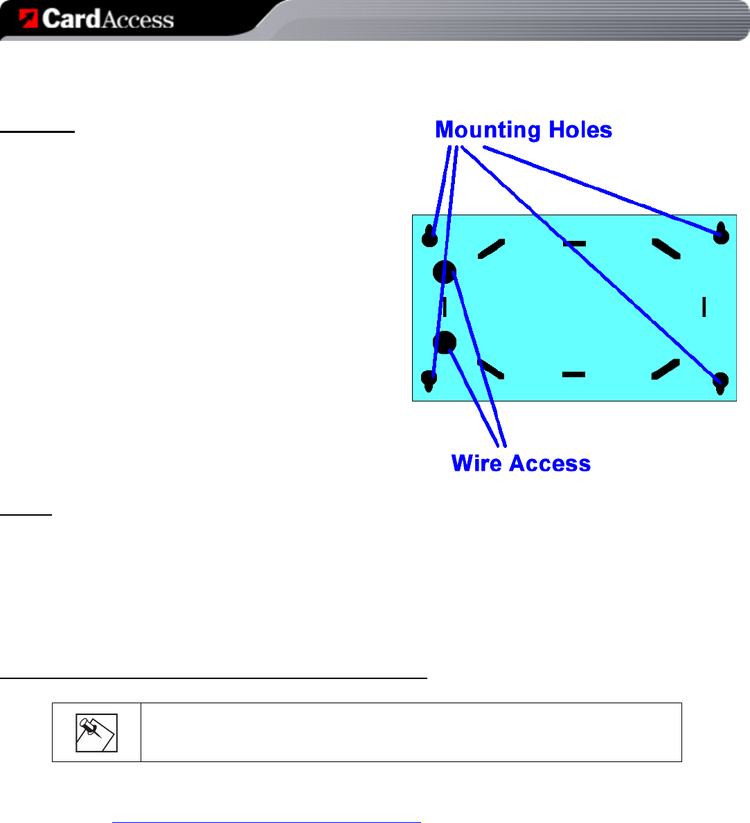
2.
Hold the bridge base against the mounting
surface and mark the four (4) mounting holes
and two (2) wire access holes as shown in
Figure 2. Remember to leave at least 10 in. (25
cm) above the bridge for the antennas.
NOTE: The circuit board may be hinged out of the bridge base
plastics to gain better access to the mounting holes by pulling
outward on the retaining latch with a finger.
3.
Drill holes and insert the appropriate anchors.
4.
Use the wire access holes to route the wires
from the DC power supply (included) into the
bridge base.
5.
Secure the bridge base to the wall with the pan
head screws provided. Figure 2 – Bridge Base Plastics
Wiring
To wire the DC power supply to the bridge, do the following:
1. Remove AC power (if applied) to the included DC power supply.
2. Wire leads of DC power supply into terminal block on the lower right side of the board. Polarity of the
wires does not matter.
3. Install metal antennas into outer slots of terminal blocks at top of board.
4. Replace cover.
Control4 Software Installation / Operation Instructions
NOTE: The Card Access Security Sensor Bridge and GE Sensors use Control4
DriverWorks™ drivers, which are not included with Composer software. They must be
downloaded from the Card Access website and manually installed.
Download and Install Drivers:
1. Go to http://www.cardaccess-inc.com/automation/drivers
2. Download the drivers you will need to use in your project.
3. Copy them to the appropriate folder on the computer you will be using to configure the project, typically “My
Documents\control4\Drivers\”
_________________________________________________________________________________________________________________________
Card Access Security Sensor Bridge V2 Page 4 of 12
Quick Start & Installation Guide Card Access, Inc.
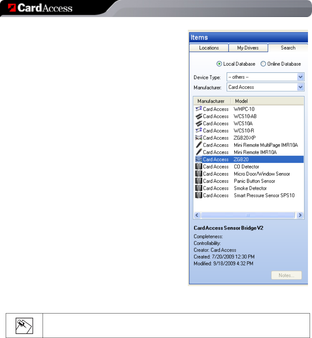
Add the Security Sensor Bridge V2 (ZGB20) to your
Composer project:
1. In System Design view in Composer, select the ‘Card
Access ZGB20’ driver from the Search tab and drag it into
your project (see figure at right).
2. Identification is similar to other Control4 ZigBee devices:
Go to Connections view in Composer and choose the
‘Network’ tab. Find the Card Access Security Sensor
Bridge device in the device list and highlight it. Then click
the ‘Identify’ button at the top of the screen.
3. When prompted to identify the unit, press the ID button on
the Bridge by using a paper clip inserted through the small
hole located on the face of the Bridge. Press the button
four times in succession. The ‘BUS’ LED on the Security
Sensor Bridge will begin blinking as it attempts to join the
ZigBee mesh and identify into the Control4 project.
4. When the Security Sensor Bridge has successfully joined
the ZigBee mesh and identified, the address of the bridge
will appear in the identification window. Click the ‘Close’
button.
To add additional Security Sensor Bridges to your
Composer project:
1. When using two or more Security Sensor Bridges in the
project, you must first add one ZGB20 driver for the first
Security Sensor Bridge. Then, you will add one instance of
the Expansion Bridge driver (ZGB20-XP) for each
additional bridge.
2. Select the Card Access ZGB20-XP driver from the Search
tab. Add one instance of the Expansion Bridge driver for
each additional bridge you will use.
3. Identify each Expansion Bridge as specified in the ZGB20
instructions above. No bindings or connections to the
primary bridge are needed.
Add wireless sensors to the project:
1. In System Design view in Composer, select the appropriate wireless sensor driver from the Search tab
and drag it into your project.
2. Navigate to the Properties page of the wireless sensor by clicking on the newly added item on the left
pane of Composer. Note that you may need to click on another item and then back on the newly added
item to force Composer to display the Properties page for the device.
3. On the Properties page, replace the text ‘unassigned’ with the 6 or 7-digit TxID printed on the label on the
wireless sensor. Then click the ‘Set’ button.
4. Test the sensor by activating/deactivating the sensor’s input. You will see the sensor status populate on
the properties page as well as the wireless signal level of the sensor-to-bridge connection.
NOTE: Ensure that the Security Sensor Bridge driver is added to the project before adding individual
wireless sensors.

_________________________________________________________________________________________________________________________
Card Access Security Sensor Bridge V2 Page 5 of 12
Quick Start & Installation Guide Card Access, Inc.
5. Select the generic proxy of your choice and at it to your project. Go to the Connections tab, and under
Control/AV, bind the output for the sensor to this proxy. DO NOT change the input bindings.
Diagnostic Indications
The Security Sensor Bridge has two LEDs which indicate its current operational state. During normal operation, these
LEDs will help to determine if the bridge is functioning properly. The tables below provide a brief summary of these LEDs:
BUS LED (top):
GREEN (solid)
Bridge is connected to Control4 automation system and operating
properly (ZigBee connection established, driver properly identified)
RED (solid)
ZigBee PRO: Bridge is not connected to the ZigBee mesh.
RED (short winks OFF)
ZigBee PRO: Bridge is connected to the ZigBee mesh but is not
communicating with the ZGB20 driver. Ensure bridge has been
identified into the system.
EmberNet: Bridge is not communicating with the ZGB20 driver.
Ensure bridge has been identified into the system.
RF LED (bottom):
GREEN (short winks ON)
Wireless sensor activity
_________________________________________________________________________________________________________________________
Card Access Security Sensor Bridge V2 Page 6 of 12
Quick Start & Installation Guide Card Access, Inc.
NOTE: The Security Sensor Bridge and its associated drivers provide a good deal of
diagnostic information to assist in deployment of Security Sensor Bridges as well as
placement and testing of wireless sensors. The information below is also included in the
Documentation tab of each driver.
ZGB20 Driver Details
• Supported Devices:
o First Security Sensor Bridge in a project
- Model Number. ZGB20
• Properties Page Help:
o Bridge Status: Displayed as “Online” or “Offline.”
NOTE: if the Security Sensor Bridge is offline, all
sensors will register as offline.
o Last Check-In: Shows the last check-in date and
time of the Security Sensor Bridge.
o Last Event: Shows the date and time of the last
sensor event, along with the TxID or name of the
sensor and the signal level.
ZGB20-XP Driver Details
• Supported Devices:
o Additional Security Sensor Bridges in the same
project
- Model Numbers. ZGB20
• Properties Page Help:
o To view diagnostic information on Expansion
Bridges, refer to the properties page of the primary Security Sensor Bridge ZGB20 driver.
Micro Door/Window Sensor Driver Details
• Supported Devices:
o GE Micro Door/Window Sensor
- Card Access Model Number: GMS10A
- GE Model Number: NX-454
o GE Recessed Micro Door/Window Sensor
- Card Access Model Number: GRS10A
- GE Model Number: 60-741-95
NOTE: This driver MUST be used in conjunction with the Card Access Security Sensor Bridge hardware and DriverWorks
driver. GE Wireless Sensors do NOT need to be associated in any way with a specific Security Sensor Bridge in
Composer.

_________________________________________________________________________________________________________________________
Card Access Security Sensor Bridge V2 Page 7 of 12
Quick Start & Installation Guide Card Access, Inc.
• Properties Page Help:
o Sensor TxID: Enter the TxID printed on the Sensor Label. The TxID is a 6 or 7-digit alphanumeric address.
o Sensor Name: An optional descriptive name may be entered here. This name is displayed on the property
page of the Bridge when data for this sensor is received.
o Sensor Contact State: shows the current state of the contact as "Opened" or "Closed."
o Sensor Status: shows whether the sensor as "Online" or "Offline." This status is affected by the connection
state of the Security Sensor Bridge(s).
o Last Sensor Event: shows the date and time of the last event received, as well as the contact status and low-
battery status.
o Last Signal Level: shows the approximate signal level of the last received event. Use this level to aid in proper
positioning of sensors.
o Supervisory Timeout: sets the number of supervisory periods which must be missed before the “Supervisory
Lost” event is triggered. Supervisory periods for these sensors are every 64 minutes.
o Supervisory State: shows current state of the supervisory signal monitor.
o Statistics: shows the number of events and RX success of the sensor.
• Actions Page Help:
• Identify Sensor: Click this button to allow the driver to automatically 'learn' the TxID of the sensor. After clicking
the button, activate the 'Tamper' switch on the sensor as follows:
o Micro/Door Window Sensor: Remove the sensor cover and slide the battery about half-way out of the battery
holder. When finished, slide the battery back in. When the sensor has been
successfully identified, the TxID will appear in the Sensor TxID field of the Driver
Properties page.
o Recessed /Door Window Sensor: Insert the blade of a standard screwdriver into the
slot at the top of the sensor. Press in firmly while slowly rotating the top 1/8 turn
counter-clockwise, then rotate it back. When the sensor has been successfully
identified, the TxID will appear in the Sensor TxID field of the Driver Properties page.
• Cancel Identify: Click this button to abort the sensor identify process. Note that clicking
this button is not necessary if you have successfully identified a sensor.
Panic Button Sensor Driver Details
• Supported Devices:
o GE Water-Resistant Panic Pendant
- Card Access Model Number: GPB10A
- GE Model Number: NX-475
o GE Multi-Purpose Panic Button
- Card Access Model Number: GMP10A
- GE Model Number: 60-906-95
NOTE: This driver MUST be used in conjunction with the Card Access
Security Sensor Bridge hardware and DriverWorks driver. GE Wireless
Sensors do NOT need to be associated in any way with a specific Security
Sensor Bridge in Composer.
• Properties Page Help:
o Sensor TxID: Enter the TxID printed on the Sensor Label. The TxID is a 6 or 7-digit alphanumeric address.

_________________________________________________________________________________________________________________________
Card Access Security Sensor Bridge V2 Page 8 of 12
Quick Start & Installation Guide Card Access, Inc.
o Sensor Name: An optional descriptive name may be entered here. This name is displayed on the property
page of the Bridge when data for this sensor is received.
o Panic Button Contact State: shows the current state of the contact as "Opened" or "Closed."
o Sensor Status: shows whether the sensor as "Online" or "Offline." This status is affected by the connection
state of the Sensor Bridge(s).
o Last Sensor Event: shows the date and time of the last event received, as well as the contact status and low-
battery status.
o Last Signal Level: shows the approximate signal level of the last received event. Use this level to aid in proper
positioning of sensors.
o Supervisory Timeout: sets the number of supervisory periods which must be missed before the “Supervisory
Lost” event is triggered. Supervisory periods for these sensors are every 64 minutes.
o Supervisory State: shows current state of the supervisory signal monitor.
o Statistics: shows the number of events and RX success of the sensor.
• Actions Page Help:
• Identify Sensor: Click this button to allow the driver to automatically 'learn' the TxID of the sensor. After clicking
the button, activate the 'Panic' condition on the sensor by pressing and holding the panic button. When the sensor
has been successfully identified, the TxID will appear in the Sensor TxID field of the Driver Properties page.
• Cancel Identify: Click this button to abort the sensor identify process. Note that clicking this button is not
necessary if you have successfully identified a sensor.
Smoke Detector Driver Details
• Supported Devices:
o GE Supervised Wireless Smoke Detector
- Card Access Model Number: GSD10A
- GE Model Number: TX-6010-01-1
NOTE: This driver MUST be used in conjunction with the Card
Access Security Sensor Bridge hardware and DriverWorks driver.
GE Wireless Sensors do NOT need to be associated in any way with
a specific Security Sensor Bridge in Composer.
• Properties Page Help:
o Sensor TxID: Enter the TxID printed on the Sensor Label.
The TxID is a 6 or 7-digit alphanumeric address.
o Sensor Name: An optional descriptive name may be entered here. This name is displayed on the property
page of the Bridge when data for this sensor is received.
o Alarm Contact State: shows the current state of the alarm as "Alarm" (meaning smoke is detected) or "No
Alarm" (meaning no smoke has been detected).
o Sensor Status: shows whether the sensor as "Online" or "Offline." This status is affected by the connection
state of the Security Sensor Bridge(s).
o Last Sensor Event: shows the date and time of the last event received, as well as the contact status and low-
battery status.
o Last Signal Level: shows the approximate signal level of the last received event. Use this level to aid in proper
positioning of sensors.
_________________________________________________________________________________________________________________________
Card Access Security Sensor Bridge V2 Page 9 of 12
Quick Start & Installation Guide Card Access, Inc.
o Supervisory Timeout: sets the number of supervisory periods which must be missed before the “Supervisory
Lost” event is triggered. Supervisory periods for these sensors are every 64 minutes.
o Supervisory State: shows current state of the supervisory signal monitor.
o Statistics: shows the number of events and RX success of the sensor.
• Actions Page Help:
• Identify Sensor: Click this button to allow the driver to automatically 'learn' the TxID of the sensor. After clicking
the button, activate the 'Tamper' signal on the smoke detector by separating the unit from the mounting base.
When the sensor has been successfully identified, the TxID will appear in the Sensor TxID field of the Driver
Properties page.
• Cancel Identify: Click this button to abort the sensor identify process. Note that clicking this button is not
necessary if you have successfully identified a sensor.
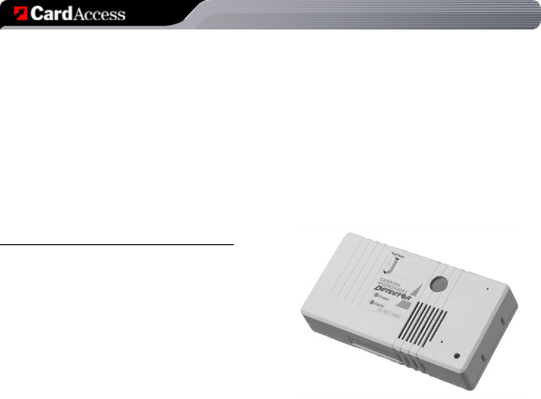
Carbon Monoxide Detector Driver Details
• Supported Devices:
o GE Wireless Carbon Monoxide Detector
- Card Access Model Number: GCO10A
- GE Model Number: 60-652-95
NOTE: This driver MUST be used in conjunction with the
Card Access Security Sensor Bridge hardware and
DriverWorks driver. GE Wireless Sensors do NOT need to
be associated in any way with a specific Security Sensor
Bridge in Composer.
• Properties Page Help:
o Sensor TxID: Enter the TxID printed on the Sensor Label. The TxID is a 6 or 7-digit alphanumeric address.
o Sensor Name: An optional descriptive name may be entered here. This name is displayed on the property
page of the Bridge when data for this sensor is received.
o Alarm Contact State: shows the current state of the alarm as "Alarm" (meaning CO is detected) or "No
Alarm" (meaning no CO has been detected).
o Sensor Status: shows whether the sensor as "Online" or "Offline." This status is affected by the connection
state of the Security Sensor Bridge(s).
o Last Sensor Event: shows the date and time of the last event received, as well as the contact status and low-
battery status.

_________________________________________________________________________________________________________________________
Card Access Security Sensor Bridge V2 Page 10 of 12
Quick Start & Installation Guide Card Access, Inc.
Regulatory Statements
FCC
The Card Access Security Sensor Bridge complies with standards established by the following regulatory bodies:
Federal Communications Commission (FCC), Conformité Européene (CE), and Restriction of Hazardous
Substances (RoHS).
FCC ID: MHIZGB20
This device complies with Part 15 of the FCC Rules. Operation is subject to the following two conditions: (1) this
device may not cause harmful interference, and (2) this device must accept any interference received, including
interference that may cause undesired operation.
This equipment has been tested and found to comply with the limits for a Class B digital device, pursuant to Part
15 of the FCC Rules. These limits are designed to provide reasonable protection against harmful interference in a
residential installation. This equipment generates, uses, and can radiate radio frequency energy and, if not
installed and used in accordance with the instructions, may cause harmful interference to radio communications.
However, there is no guarantee that interference will not occur in a particular installation. If this equipment does
cause harmful interference to radio or television reception, which can be determined by turning the equipment off
and on, the user is encouraged to try to correct the interference by one or more of the following measures:
• Reorient or relocate the receiving antenna.
• Increase the separation between the equipment and receiver.
• Connect the equipment into an outlet on a circuit different from that to which the receiver is connected.
• Consult the dealer or an experienced radio/TV technician for help.
IMPORTANT! Changes or modifications not expressly approved by Card Access, Inc. void the user’s authority to
operate the equipment.
CE
We, Card Access, Inc. of 11778 South Election Road, Suite 260, Salt Lake City, Utah, 84020 USA, declare under
our sole responsibility that the Card Access Security Sensor Bridge, Model Number ZGB20, to which this
declaration relates, is in conformity with the following standards and / or other normative documents:
EN60950, EN55022, EN55024
We hereby declare that the above named product is in conformity with the essential requirements and other
relevant provisions of Directive 1999/5/EC. The conformity assessment procedure referred to in Article 10(3) and
detailed in Annex II of Directive 1999/5/EC has been followed.
Industry Canada
IC: 3681C-ZGB20
This Class B digital apparatus complies with Canada ICES-003.
Cet appareil numérique de la classe B est conforme à la norme NMB-003 du Canada.
Operation is subject to the following two conditions: (1) this device may not cause interference, and (2) this device
must accept any interference, including interference that may cause undesired operation of the device.
Operation c'est thème aux suivant deux conditions : (1) ça truc Mai pas raison parasites , et (2) ça truc devoir
agréer tout parasites , incluant parasites thanksggiving Mai raison peu souhaitable les fonctionnements de les
truc.

_________________________________________________________________________________________________________________________
Card Access Security Sensor Bridge V2 Page 11 of 12
Quick Start & Installation Guide Card Access, Inc.
One-Year Limited Warranty
This product is warranted to be free of defects in material and workmanship for one year from date of original purchase from Card Access, Inc.
(“Card Access”).
Card Access will, at its election and as the purchaser’s or end user’s sole and exclusive remedy for any breach of the limited warranty set forth
above, repair or replace this product if a defect in material or workmanship is identified and communicated to Card Access within the one-year
period described above. Card Access is not responsible for removal or reinstallation costs. This warranty is not valid in cases where damage
to this product is the result or arises out of misuse, abuse, incorrect repair or improper wiring or installation.
To notify Card Access of any breach of the foregoing limited warranty and to obtain warranty service, contact Card Access Customer Support
by e-mail to inhomesupport@cardaccess-inc.com or by calling 801-748-4900, extension 15, to obtain a Return Materials Authorization
(“RMA”) number and instructions for returning your defective product to Card Access.
IMPLIED WARRANTIES, INCLUDING THOSE OF MERCHANTABILITY AND FITNESS FOR A PARTICULAR PURPOSE, ARE
EXPRESSLY DISCLAIMED, EXCEPT WHERE SUCH DISCLAIMER IS PROHIBITED BY APPLICABLE LAW. CARD ACCESSAND/OR THE
SELLER DISCLAIM(S) ANY AND ALL LIABILITY FOR SPECIAL,INCIDENTAL AND CONSEQUENTIAL DAMAGE IN ANY WAY
ASSOCIATED WITH OR RELATED TO THE PURCHASE, INSTALLATION AND/OR USE OF THISPRODUCT.
Some states/provinces do not allow limitations on how long an implied warranty lasts, or the exclusion or limitation of special, incidental or
consequential damages, so these limitations and exclusions may not apply to you. This warranty gives you specific legal rights. You may also
have other rights which vary from state/province to state/province. This is Card Access’ exclusive written warranty.
QSG-ZGB-INST20
The information contained in this document represents current information and views of Card Access, Inc. as of the date of
publication. Card Access cannot guarantee the accuracy of any information presented after the date of this document’s publication.
COPYRIGHT ©2010 Card Access, Inc. All rights reserved. Any previously copyrighted contents contained herein remain the
property of the respective creators.

_________________________________________________________________________________________________________________________
Card Access Security Sensor Bridge V2 Page 12 of 12
Quick Start & Installation Guide Card Access, Inc.
Card Access and The Wire Stops Here are trademarks of Card Access, Inc.
Control4 is a registered trademark and 4Sight is a trademark of Control4 Corporation.
ZigBee and ZigBee PRO are trademark of the ZigBee Alliance.
Other marks may be the property of their respective owners.