Carl Zeiss Surgical 304970-9400 Upgrade Module User Manual G 30 1707 bk
Carl Zeiss Surgical GmbH Upgrade Module G 30 1707 bk
UserManual.wiki
>
Carl Zeiss Surgical
>
304970 9400 User Manual
User Manual
Navigation menu
Upload a User Manual
Namespaces
Wiki Guide
HTML
PDF
Info
Views
User Manual
Discussion / Help
Navigation

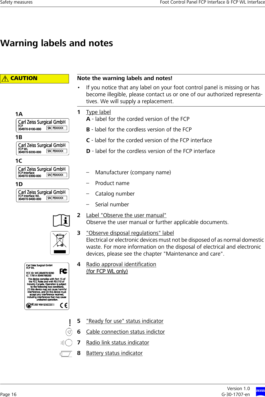
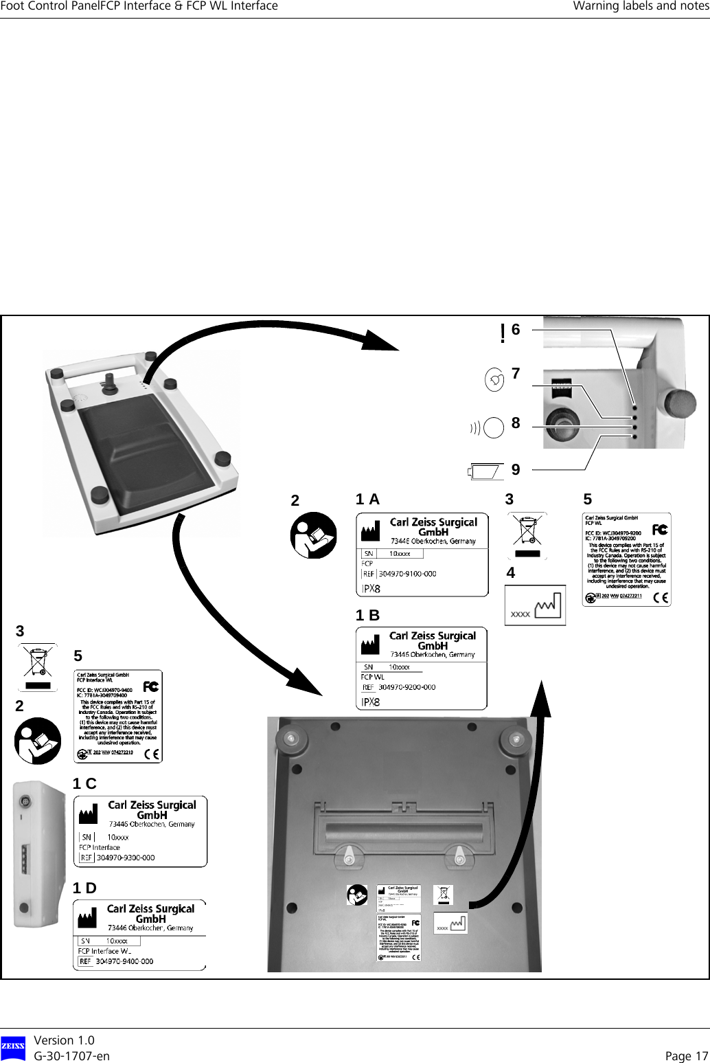
![Version 1.0G-30-1707-en Page 11Foot Control PanelFCP Interface & FCP WL Interface Notes for the operatorNOTE Limit values for digital devicesThis component has been tested and found to comply with the limits for a Class B digital device in accordance with Part 15 of FCC regulations. These limits have been stipulated to provide adequate protection against harmful exposure when the component is operated in residential areas. This compo-nent generates and uses radio frequency energy and may emit such energy. If not installed and used in accordance with the relevant instructions, it may cause interference to radio communication. However, there is no guarantee that interference will not occur in a particular installation. If this component causes interference with radio and TV reception, which can be determined by turning the component off and on, the user should try to correct the in-terference by one or several of the following measures:– Relocate or reorient the receiving antenna.– Move the component further away from the receiver.– Plug the component into a different outlet so that it is not on the same circuit as the receiver.– Consult an experienced radio/TV technician.NOTE Part 15 of FCC regulationsThis component complies with Part 15 of FCC regulations [and with the In-dustry Canada RSS-210 standard].Operation of the component is subject to the following two conditions:– the component must not cause any harmful interference and – the component must accept any interference received, including interfer-ence that may cause undesired operationNOTE Modification or conversionAny modification or conversion not explicitly approved by Carl Zeiss will in-validate the FCC license for the operation of this component.](https://usermanual.wiki/Carl-Zeiss-Surgical/304970-9400/User-Guide-1065131-Page-11.png)