Carol Electronics Co CAROLDW25T Digital Wireless Microphone User Manual DW25 EN
Taiwan Carol Electronics Co Ltd Digital Wireless Microphone DW25 EN
User manual
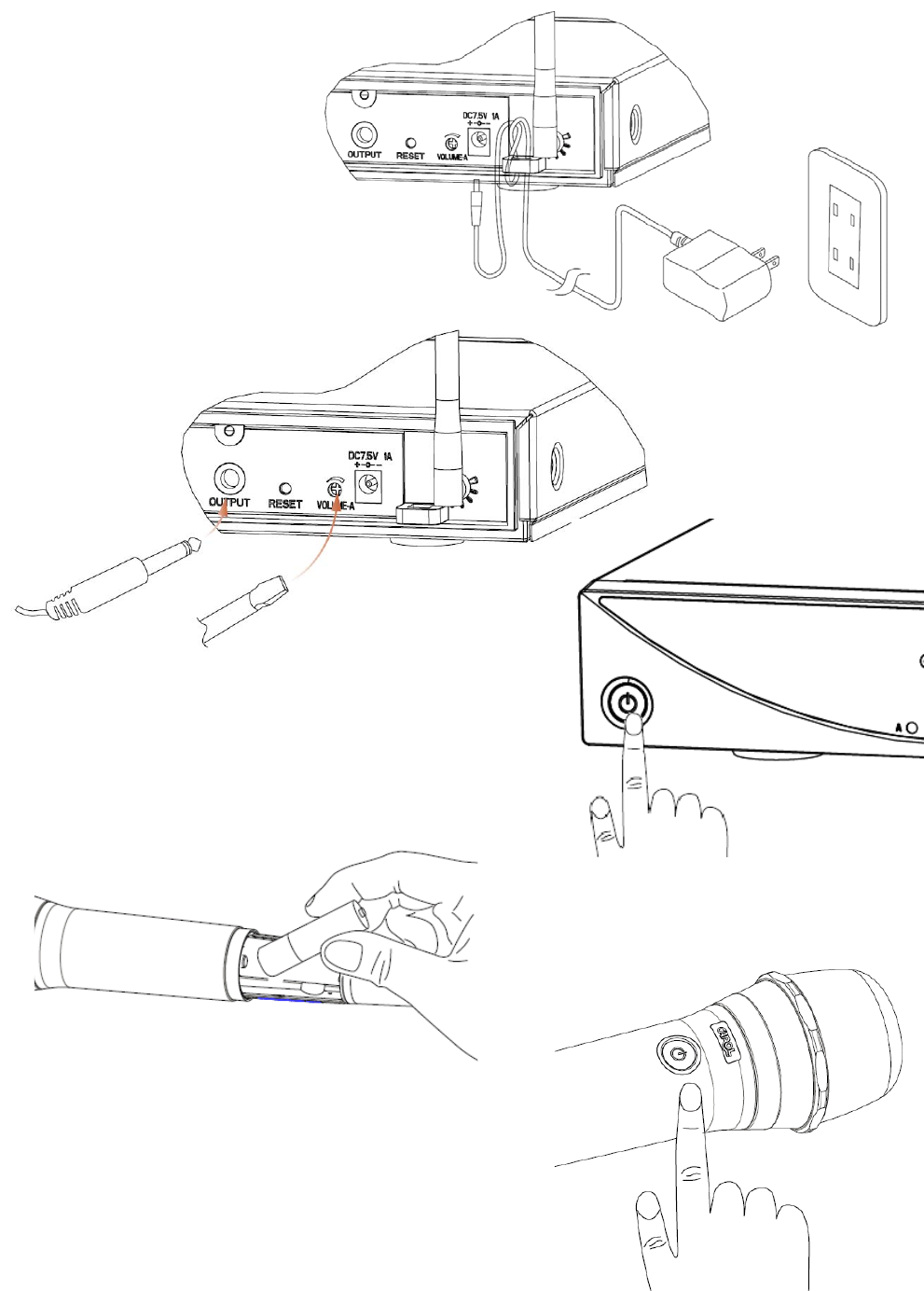
QuickInstallationGuide
Plugthepower
PlugtheAudiocable,andthen
adjustthevolume
Turnthe
Receiver’spoweron
Insertbatteries
Turnthe
Microphone’spoweron
ThankyouverymuchforselectingDW‐25DigitalWirelessSystem.Itisrecommendedto
readthismanualcarefullybeforeusingtomakeoptimumuseoftheequipment.
DW‐25DigitalWirelessSystem,basedontheconceptofdesigningformodernlifestyle,
withgracefulcurve,finetextureanduserfriendlydesign,issuitableforallkindsofscenario
infamily,karaoke,school,company,organization,oranyplacethatrequiresthemobility
functionofthewirelessmicrophone.
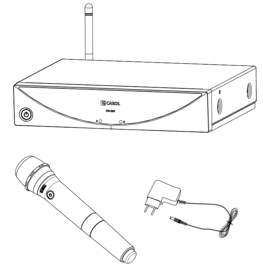
1. DW‐25DigitalWirelessSystemProductContents:
1.1 DW‐25RDigitalWirelessReceiverX1
1.2 DW‐25THandheldDigitalWirelessMicrophoneX2
1.3 InternationalVoltageDC7.5VPowerAdapterX1
1.4 ø6.3mmM‐XLR/M‐XLRCableX1
1.5 User’sManualX1
PowerAdapter
WirelessReceiver
WirelessMicrophone
2. PartsandFunctions:
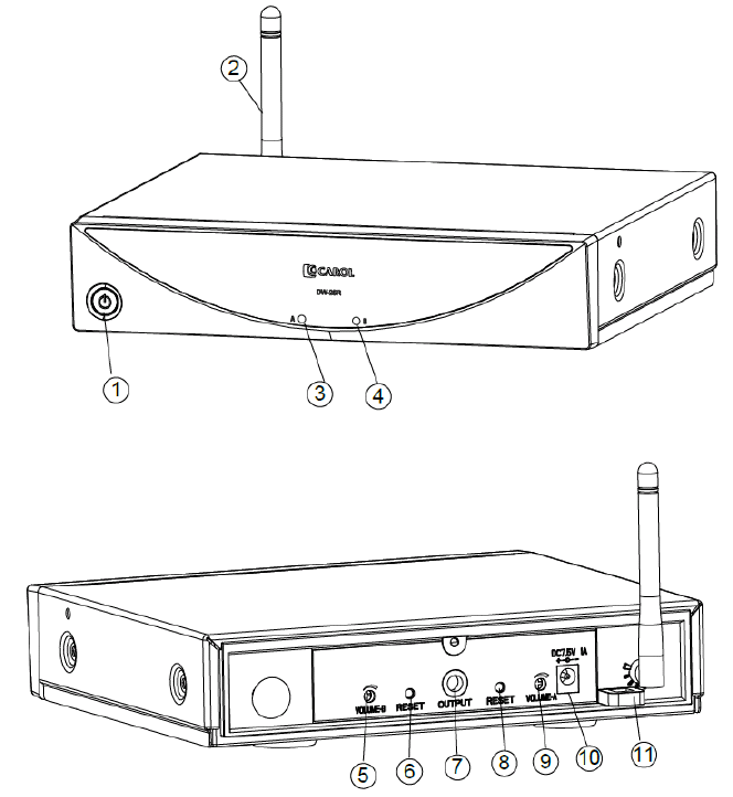
2.1 DW‐25RDigitalWirelessReceiver(asshowninFigure2.1)
(1) PowerSwitch:Switcheson/offtheReceiver,withstatusLED.
(2) Antenna:Receivessignalsfromthemicrophone.Theangleoftheantennascanbe
adjustedleftward,rightwardorbackward.
(3) MicAConnectingLED:LightsupwhenmicrophoneAissuccessfullyconnected.
(4) MicBConnectingLED:LightsupwhenmicrophoneBissuccessfullyconnected.
(5) MicBVolumeController:ControlstheoutputvolumeofmicrophoneB.
(6) MicBResetButton:ResetsmicrophoneBsignals.
(FORTECHNICIANSUSEONLY)
(7) ø6.3mmFemaleJack:Connectstothesignaloutputofanamplifier.
(8) MicAResetButton:ResetsmicrophoneAsignals.
(FORTECHNICIANSUSEONLY)
(9) MicAVolumeController:ControlstheoutputvolumeofmicrophoneA.
(10) DCPowerReceptacle:ConnectsDCadapter.Thepolarityofcentralpoleispositive.
(11) CableClasp:Forsecurethepowercable.
Figure2.1
2.2 DW‐25THandheldDigitalWirelessMicrophone(asshowinFigure2.2)
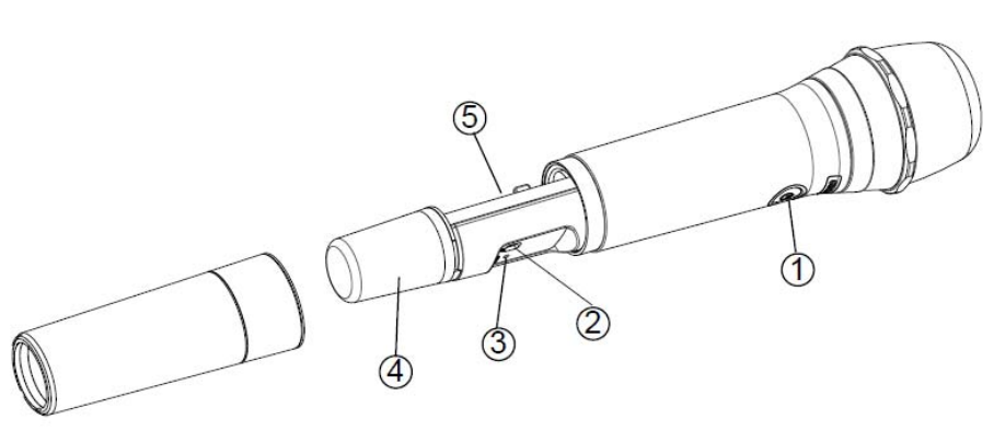
(1) PowerSwitch:Switcheson/offthemicrophone(withstatusLED).
(2) DistanceSwitch:Adjustslong,medium,shortrangeofdistance.
(3) MicrophoneResetButton:ResetsmicrophoneAsignals.
(FORTECHNICIANSUSEONLY)
(4) AntennaCover:Protectstheantenna,andthemicrophonescanbeeasilyidentified
withdifferentcolorcovers.(Donotholdontothisareawhileusingthemicrophone)
(5) BatteryCompartment:AccommodatestwoAAbatteries.
Figure2.2
3. DigitalWirelessMicrophoneOperatingInstruction
3.1 SetUptheSystem
3.1.1 PressthePowerSwitchontheMicrophonetoturnthepoweron,andthe
statusLEDwilllightupgreen;itindicatestheMicrophonepowerison.Ifthe
LEDkeepsblinking,itindicatesthemicrophoneisnotconnectedwiththe
Receiver.
3.1.2 IfthepoweroftheReceiverhasbeenturnedon,andtheMicrophone
ConnectingLEDontheReceiverlightsupred,itindicatestheReceiverhas
receivedtheMicrophonesignals.Meanwhile,thePowerSwitchstatusLEDon
theMicrophonewilllightupcontinuingly,theusercannowtalkintothe
Microphone.
3.1.3 Forbestresult,keeptheMicrophonetothesoundsourceinbetween2‐5cm.
3.1.4 AdjustthevolumetooloudormovetheMicrophonetooclosetothe
loudspeakermightcauseannoyingfeedback.Whenithappens,pleaseturn
downthevolumeonReceivertoavoidfeedback.
3.2 TurnOfftheSystem
PressonthePowerSwitchontheMicrophone,andthestatusLEDwillgooff.When
theMicrophonepowerisoff,theMicrophoneConnectingLEDontheReceiverwill
alsogooff.PressontheReceiverPowerSwitchtillthegreenpowerstatusLEDgoes
offtocompletethesystemturnoff.
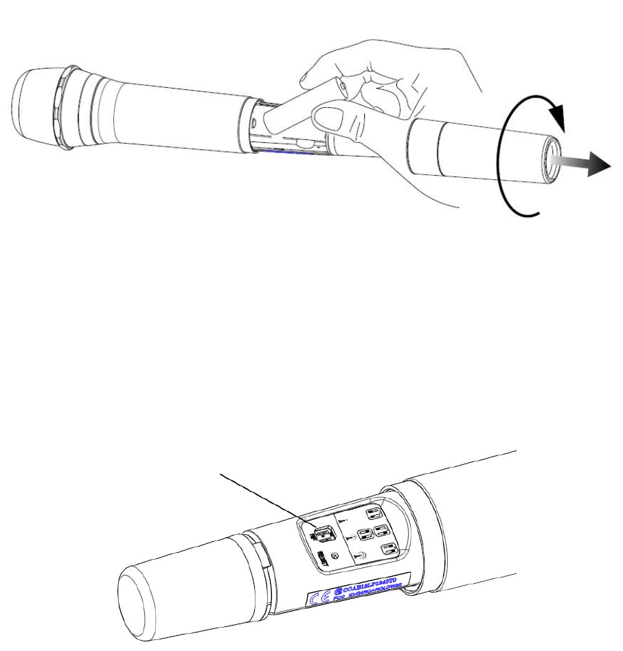
3.3 ReplaceBatteries:
3.3.1 WhentheMicrophoneison,andithasalreadyconnectedwiththeReceiver,
butthepowerstatusLEDonMicrophonekeepsblinkinggreen,itindicatesthe
batteryenergyisrunninglow.Pleasereplacethebatteries.
3.3.2 RemovetheMicrophonehousingandreplacetwonewAAbatteriesinthe
BatteryCompartmentaccordingtothepolaritymarks.
3.3.3 PutbacktheMicrophonehousing.
Figure3.1
3.4 DistanceAdjustment
3.4.1 AdjusttheDistanceSwitchaccordingtotherequireddistancerange.Three
distancesavailable,long(approx.30M),medium(approx.20M),short(approx.
10M).Usingshorterdistancewillincreasethebatterylife.
3.4.2 DistanceSwitchlocationasshowinFigure3.2.
3.4.3 DistanceSwitchadjustmentasshowninFigure3.3.
Figure3.2
DistanceSwitch
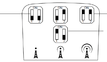
Figure3.3
4. Pairing(FORTECHNICIANSUSEONLY)
4.1 PlugthePowerAdaptertoDW‐25R,andthenturnthepoweron.
4.2 InstallbatteriesinDW‐25T,andthenturnthepoweron.
4.3 PresstheResetButtonontheReceiver,andthecorrespondingLEDwillblink.
4.4 PresstheResetButtonontheDW‐25T,andtheMicrophoneLEDwillblink.
4.5 TheMicrophoneLEDandReceiverAchannelorBchannelLEDwillblink
simultaneously,itindicatestheautopairingisactivatedbytheprogram.The
pairingprocesstakesabout10‐20seconds,andthentheLEDonthepaired
productswilllightupcontinuingly,itindicatesthepairingprocessiscompleted.
4.6 Ifthepairingprocessfailed,pleaserepeat4.3‐4.4,andspeeduptheprocess.
5. Troubleshooting:
5.1 WirelessReceivercannotbepoweredon:checkifthepowertotheReceiveriswell
connected.
5.2 ThestatusLEDonWirelessMicrophonenotlightupwhenpowerison:checkifthe
batteriesareproperlyinstalledorhaveenoughenergy.
5.3 ThestatusLEDonWirelessMicrophonekeepsblinking:Checkifthebatterieshave
enoughenergy,oriftheReceiverispoweredon.
5.4 Nosound:Checkifthevolumeissettoolow,orifthesoundcableiswell
connected.
5.5 ThemaximumeffectivedistancebetweentheDigitalWirelessMicrophoneandthe
DigitalWirelessReceiveris30M(whentheDistanceSwitchissetat“long”),sothe
outputaudiomightbeinconsistentwhenbeyondtheeffectiverange.
6. Specification:
6.1 DigitalWirelessReceiver:
Model:DW‐25R
PowerConsumption:7.5W(MAX)
Long
Short
Medium
ReceivingSensitivity:‐82dBm
OutputJack:ø6.3mmFemaleJack
Dimension:210(L)×182(W)×105(H)mm
Weight:800g50g
6.2 HandheldDigitalWirelessMicrophone:
Model:DW‐25T
CarrierFrequency:2.403G~2.478GHz
Capsule:Dynamic
PolarPattern:Super‐Cardioid
Impedance:600Ω
FrequencyResponse:80Hz~12000Hz
PowerConsumption:65mA
PowerSupply:TwoAAbatteries
DistanceSwitch:long(approx.30M),medium(approx.20M),short(approx.10M)
BatteryLife:Approx.30hours(alkalinebattery)
Dimension:ø54.4×258.5mm(L)
Weight:380g10g(w/obatteries)
6.3 PowerAdapter:
Input:AC100‐240V
Output:DC7.5V/1A
7. Certifications:Thisproductcomplieswiththefollowingessentialrequirementsandthe
relatedstandard:
7.1 CE
7.1.1 EMC:EN301489‐1/EN301489‐3
7.1.2 RF:EN300440
7.1.3 LVD:EN60065
7.2 FCC
7.2.1 Tx:FCCPart15C(Certification)
7.2.2 Rx:FCCPart15BDoC
7.3 NCC
(Tx+Rx):LP0002
8. FCCComplianceStatement
8.1 Changes or modifications made to this device not expressly approved by the
manufacturer may void the FCC authorization to operate this device.
8.2 In order to comply with the regulations of FCC Radiated Emission Limits, do not
place or operate this Transmitter and its antenna together with another antenna or
transmitter.
8.3 Thisdevicecomplieswithpart15oftheFCCRules.Operationissubjecttothe
followingtwoconditions:(1)Thisdevicemaynotcauseharmfulinterference;
(2)Thisdevicemustacceptanyinterferencereceived,includinginterferencethat
maycauseundesiredoperation.
Note: This equipment has been tested and found to comply with the limits for a
Class B digital device, pursuant to part 15 of the FCC Rules. These limits are
designed to provide reasonable protection against harmful interference in a
residential installation. This equipment generates, uses and can radiate radio
frequency energy and, if not installed and used in accordance with the
instructions, may cause harmful interference to radio communications. However,
there is no guarantee that interference will not occur in a particular installation. If
this equipment does cause harmful interference to radio or television reception,
which can be determined by turning the equipment off and on, the user is
encouraged to try to correct the interference by one or more of the following
measures:
—Reorient or relocate the receiving antenna.
—Increase the separation between the equipment and receiver.
—Connect the equipment into an outlet on a circuit different from that to which
the receiver is connected.
—Consult the dealer or an experienced radio/TV technician for help.
For DW-25R
IMPORTANT NOTE: To comply with the FCC RF exposure compliance
requirements, the antenna(s) used for this transmitter must be installed to provide
a separation distance of at least 20 cm from all persons and must not be co-
located or operating in conjunction with any other antenna or transmitter. No
change to the antenna or the device is permitted. Any change to the antenna or
the device could result in the device exceeding the RF exposure requirements
and void user’s authority to operate the device.
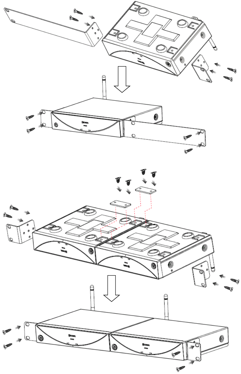
※ InstructiononmountingtheReceiverinthecabinet(mountingbracketsareoptional
accessories)
(1) MountingaReceiverin1Ucabinet
(2) Mounting2Receiversin1Ucabinet