Carrier Access Bank Ii Snmp Users Manual Ab2snmp.bk
Access Bank II SNMP 52f67dfe-5d8f-4cad-b147-a865d12ffd44
SNMP to the manual 52f67dfe-5d8f-4cad-b147-a865d12ffd44
2015-02-05
: Carrier-Access Carrier-Access-Access-Bank-Ii-Snmp-Users-Manual-530553 carrier-access-access-bank-ii-snmp-users-manual-530553 carrier-access pdf
Open the PDF directly: View PDF ![]() .
.
Page Count: 180 [warning: Documents this large are best viewed by clicking the View PDF Link!]
- Access Bank II Cover
- FCC Requirements
- Safety Requirements
- National Electrical Code Requirements
- Industry Canada Requirements
- Warranty
- Warranty Product Returns
- Advice to the Reader
- How To Use This Manual
- Table of Contents
- Chapter 1 Introduction
- Chapter 2 Product Description
- Chapter 3 Technical Specifications
- 3.1 About This Chapter
- 3.2 Dual T1 Network Line Interfaces
- 3.3 Line Codes
- 3.4 Framing
- 3.5 Clock Source
- 3.6 T1-to-T1 Delay
- 3.7 T1 Channel Service Units (CSUs)
- 3.8 Digital Data Ports
- 3.9 Analog Line Interfaces
- 3.10 FXS Voice Card
- 3.11 FXO/DPT Voice Card
- 3.12 4-Wire E&M/TO Voice Card
- 3.13 Network Management
- 3.14 Alarms
- 3.15 Control Panel I/O Connectors
- 3.16 Standards Compliance
- 3.17 Power
- 3.18 Environmental
- 3.19 Installation
- Chapter 4 Physical Installation
- Chapter 5 Electrical Installation
- Chapter 6 Basic Configuration
- Chapter 7 Remote Monitor
- Chapter 8 FXS-ID Configuration
- Chapter 9 BRFXS & DPO
- Chapter 10 12-Channel FXO & DPT
- Chapter 11 4-Wire E&M/TO
- 11.1 About This Chapter
- 11.2 4-Wire E&M/TO Voice Card
- 11.3 Typical Applications
- 11.4 E&M Signaling Conventions
- 11.5 Programming E&M Signaling Types
- 11.6 Detector Configuration
- 11.7 Normal and Tandem Cables
- 11.8 Configuring Signaling Types and Trunk Processing
- 11.9 TP Busy/Idle Switch
- 11.10 Setting Transmit and Receive Gain
- 11.11 Transmit (Analog-to-Digital) Gain
- 11.12 Receive (Digital-to-Analog) Gain
- 11.13 E&M Voice Channel Monitoring
- 11.14 E&M Normal mode cable
- 11.15 E&M Tandem Mode Cable
- Chapter 12 Diagnostics & Troubleshooting
- 12.1 About This Chapter
- 12.2 Diagnostic Switches
- 12.3 Self Test 1 and 2
- 12.4 Self Test Fault Indications
- 12.5 1 kHz Digital Milliwatt Test Signal
- 12.6 Network Loopback 1 and 2
- 12.7 Remote Mode: Remote T1 Line or Payload Loopbacks
- 12.8 ANSI T1.403 Remote T1 LLB
- 12.9 Illustrations of Loops and Self-Tests
- 12.10 Disabling an External Alarm
- 12.11 LED Test and Status Indicators
- 12.12 Fault Isolation Procedures
- 12.13 Back Plate Indications
- 12.14 Other Fault Indications
- 12.15 Access Bank II - SNMP Shuts Down for No Apparent Reason
- Chapter 13 Maintenance
- Chapter 14 SNMP Management & CLI
- Glossary

Access Bank II -
SNMP
INSTALLATION & USER’S GUIDE
5395 Pearl Parkway
Boulder, CO 80301-2490
fax 303-546-9724
http://www.carrieraccess.com
Part Number 002-0097-0200
Release 2.0
September 2001
Copyright© 1998 Carrier Access Corporation. All rights reserved.
The information presented in this manual is subject to change without notice and does not represent a commit-
ment on the part of Carrier Access Corporation. The hardware and software described herein are furnished under
a license or non-disclosure agreement. The hardware, software and manual may be used or copied only in ac-
cordance with the terms of this agreement. It is against the law to reproduce, transmit, transcribe, store in a re-
trieval system, or translate into any medium - electronic, mechanical, magnetic, optical, chemical, manual or
otherwise - any part of this manual or software supplied with the Access Bank II - SNMP for any purpose other
than the purchaser’s personal use without the express written permission of Carrier Access Corporation.
The Carrier Access Logo is a registered trademark of Carrier Access Corporation.
The information contained in this manual applies to Carrier Access Corporation’s Access Bank II - SNMP.
FCC REQUIREMENTS
FCC Requirements, Part 15
This equipment has been tested and found to comply with the limits for a Class A digital device pursuant to Part
15 of the Federal Communications Rules. These limits are designed to provide reasonable protection against
harmful interference when equipment is operated in a commercial environment. This equipment generates, uses,
and can radiate radio frequency energy, and if not installed and used in accordance with the instruction manual
may cause harmful interference to radio communications. Operation of this equipment in a residential area is
likely to cause harmful interference, in which case the user will be required to correct the interference at the
user’s own expense.
FCC Requirements, Part 68Exhibit J1
This equipment complies with Part 68 of the FCC rules. The label attached to the top cover of the housing of
the Carrier Access Corporation Access Bank II - SNMP contains, along with other information, the FCC regis-
tration number. You must supply this information to the telephone company, if they request it.
FCC Registration Number: 2ZUSA-22437-DD-N
Ringer Equivalence: REN 0.4B
Service Center in the USA:
Carrier Access Corporation
5395 Pearl Parkway
Boulder, CO 80301-2490
The Facility Interface Code (FIC) associated with each private line application represents the type of service that
will be provided by the telephone company. The following are currently registered:
If the Access Bank II - SNMP causes harm to the telephone network, the telephone company will notify you in
advance. If advance notice proves impractical, the telephone company will notify the customer as soon as pos-
sible. Also, you will be advised of your right to file a complaint with the FCC if you believe such action is nec-
essary.
The telephone company may make changes in its facilities, equipment operations, or procedures that could ef-
fect the operation of the Access Bank II - SNMP. If this occurs, the telephone company will provide advance
notice so that you may make necessary modifications to maintain uninterrupted service.
If you experience trouble with the Access Bank II - SNMP, please first contact the distributor or dealer from
which you purchased the product and then, as a second point of contact, contact CAC for repair and/or warranty
information.
If the trouble is causing harm to the telephone network, the telephone company may request that you remove
Port: FIC: SOC: Jack:
T1 1.544 Mbps 04DU9-BN 6.0n RJ48C
T1 1.544 Mbps 04DU9-DN 6.0n RJ48C
T1 1.544 Mbps 04DU9-SN 6.0n RJ48C

the Access Bank II - SNMP from the network until the problem is resolved. User repairs must not be made. Do-
ing so will void your warranty.
Do not install the Access Bank II - SNMP on public coin service provided by the telephone company. Connec-
tion to Party Line service is subject to state tariffs. (Contact your state public utilities commission for further
information.)
To minimize damage caused by local lightning strikes and other electrical surges, it is recommended that the
customer install an AC surge arrestor in the AC outlet to which the Access Bank II - SNMP is connected.
SAFETY REQUIREMENTS
DANGER! Always exercise caution when installing telephone lines.
Never touch uninsulated telephone wires and terminals unless the telephone line has been disconnected at the
Network Interface (NI) as voltage potentials as high as 300 Vac may be present across the transmit and receive
pairs.
Never install telephone wiring during a lightning storm.
Never install telephone jacks in wet locations unless the jack is specifically designed for wet locations.
Refer to the installation chapter in this manual for a safe and proper installation procedure. All wiring external
to this equipment should follow the current provision of the National Electrical Code.
NATIONAL ELECTRICAL CODE REQUIREMENTS
The Access Bank II - SNMP is CCL certified and is in compliance with ANSI/UL Std. 1459. The CCL certifi-
cation number for the product safety listing of the Access Bank II - SNMP is C86-0303.
INDUSTRY CANADA REQUIREMENTS
Load Number: 5
CP-01, Part 1
Section 10.1
“NOTICE: The Canadian Department of Communications label identifies certified equipment. This certifica-
tion means that the equipment meets certain telecommunications network protective, operational and safety re-
quirements. The Department does not guarantee the equipment will operate to the user’s satisfaction.
Before installing this equipment, users should ensure that it is permissible to be connected to the facilities of the
local telecommunications company. The equipment must also be installed using an acceptable method of con-
nection. In some cases, the company’s inside wiring associated with a single line individual service may be ex-
tended by means of a certified connector assembly (telephone extension cord). The customer should be aware
that compliance with the above conditions may not prevent degradation of service in some situations.
Repairs to certified equipment should be made by an authorized Canadian maintenance facility designated by
the supplier. Any repairs or alterations made by the user to this equipment, or equipment malfunctions, may give
the telecommunications company cause to request the user to disconnect the equipment.
Users should ensure for their own protection that the electrical ground connections of the power utility, tele-
phone lines and internal metallic water pipe system, if present, are connected together. This precaution may be
particularly important in rural areas.
CAUTION: Users should not attempt to make such connections themselves, but should contact the appropriate
electric inspection authority, or electrician, as appropriate.”
CP - 01, Part I
Section 10.2
“NOTICE: The Load Number (LN) assigned to each terminal device denotes the percentage of the total load to
be connected to a telephone loop which is used by the device, to prevent overloading. The termination on a loop
may consist of any combination of devices subject only to the requirement that the total of the Load Numbers
of all the devices does not exceed 100.”
WARRANTY
Carrier Access Corporation conditionally warrants to BUYER that PRODUCTS are free from substantial defect
in material and workmanship under normal use given proper installation and maintenance for the period of five
years from the date of shipment by CAC.
BUYER will promptly notify CAC of any defect in the PRODUCT. CAC or its agent will have the right to in-
spect the PRODUCT or workmanship on BUYER’S or BUYER’S customer premises. CAC has the option to:
(a) repair, replace or service at its factory or on the premises the PRODUCT or workmanship found to be defec-
tive; or (b) credit BUYER for the PRODUCT in accordance with CAC’s depreciation policy. Refurbished ma-
terial may be used to repair or replace the PRODUCT. PRODUCTS returned to CAC for repair, replacement,
or credit will be shipped prepaid to BUYER.
Limitations of Warranty & Limitation of Remedies
Correction of defects by repair, replacement, service or credit will be at CAC’s option and constitute fulfillment
of all obligations to buyer for breach of warranty.
CAC assumes no warranty liability with respect to defects in the PRODUCT caused by:
(a) modification, repair, installation, operation or maintenance of the PRODUCT by anyone other than CAC or
its agent, except as described in CAC’s documentation; or
(b) the negligent or other improper use of the PRODUCT; or
(c) handling or transportation after title of the PRODUCT passes to BUYER.
Other manufacturer’s equipment purchased by CAC and resold to BUYER will be limited to that manufacture’s
warranty. CAC assumes no warranty liability for other manufacturer’s equipment furnished by BUYER.
Buyer understands and agrees as follows: the warranties in this agreement replace all other warranties, expressed
or implied, and all other obligations or liabilities of CAC, including any warranties of merchantability and fit-
ness for a particular purpose. All other warranties are disclaimed and excluded by CAC.
The remedies contained in this agreement will be the sole and exclusive remedies whether in contract, tort or
otherwise, and CAC will not be liable for injuries or damages to persons or property resulting from any case
whatsoever, with the exception of injuries or damages caused by the gross negligence of CAC. These limitations
apply to all services, software, and products during and after the warranty period. In no event will CAC be liable
for any special, incidental, or consequential damages or commercial losses even if CAC has been advised there-

of.
No agent, distributor, or representative is authorized to make any warranties on behalf of CAC or to assume for
CAC any other liability in connection with any of CAC’s PRODUCTS, Software, or Services.
WARRANTY PRODUCT RETURNS
PRODUCTS may not be returned without prior assignment of a Return Material Authorization (RMA) number
from Carrier Access Corporation. Call CAC Customer Support at (800) 495-5455 or (303) 442-5455 to request
an RMA number.
PRODUCTS to be returned are subject to CAC inspection and acceptance. PRODUCTS found physically dam-
aged or modified will be returned to BUYER freight collect.
Ship authorized PRODUCT returns to:
Carrier Access Corporation
Attn.: RMA# ___________
5395 Pearl Parkway
Boulder, CO 80301 USA
ADVICE TO THE READER
This manual contains information and warnings that must be followed to ensure safe operation of the Access
Bank II - SNMP while retaining the equipment in a safe condition.
DANGER! The DANGER! sign denotes a hazard to the user and calls attention to a procedure, practice, or the like, which,
if not correctly performed, could result in injury or loss of life. Do not proceed beyond a DANGER! sign until the noted
conditions are fully understood and met.
CAUTION! The CAUTION! sign denotes the possibility of network service interruption and calls attention to a procedure
or practice, which, if not correctly performed, could result in interruption of network service.
WARNING! The WARNING! sign indicates the possibility of equipment damage and calls attention to a proce-
dure or practice, which, if performed improperly, could result in equipment damage.
Note: The NOTE sign precedes explanatory comments or supplementary instructions.
HOW TO USE THIS MANUAL
This manual is designed to give you the information needed to install, configure, and operate the Access Bank
II - SNMP. Take time to read it through completely in order to become familiar with its contents and overall
organization. Then, for quick access to most information, you can simply refer back to the Table of Contents.
This manual is organized into chapters as follows:
Chapter 1. Introducing the Access Bank II - SNMP
Provides a general introduction to the Access Bank II - SNMP including summaries of its standard functions, fea-
tures, and optional enhancements.
Chapter 2. Product Description
Describes the general physical characteristics and layout of the Access Bank II - SNMP, including the Control Panel,
digital and analog interface connectors, power connector, DIP switches and LED status indicators.
Chapter 3. Technical Specifications
Summarizes the technical specifications of the Access Bank II - SNMP, including its dual T1 network interfaces,
integral Channel Service Units (CSUs), digital data ports, analog line interfaces, network management capabil-
ities, alarms, standards, power sources and environmental operating parameters.
Chapter 4. Physical Installation
Provides procedures for physically installing the Access Bank II - SNMP including checking items required for in-
stallation and mounting the chassis and power converter.
Chapter 5. Electrical Installation
Provides procedures for installing the communication interface and power connectors on the Access Bank II -
SNMP Control Panel and bringing the unit on line.
Chapter 6. Initialization and Basic Configuration
Describes how to initialize and configure the Access Bank II - SNMP for first time basic operation in the Local mode
using the System Configuration and T1 Hardware Configuration DIP switches.
Chapter 7.12-Channel FXS Card
Describes how to configure the Foreign Exchange Station (FXS) 12-channel voice card for connection to T1
public network services and provides instructions for setting signaling options and channel attenuation levels,
and performing voice channel monitoring and testing.
Chapter 8. 12-Channel FXO Card
Describes how to configure the Foreign Exchange Office (FXO) 12-channel voice card for connecting the Access
Bank II - SNMP to T1 public network services and provides instructions for optioning the FXO.
Chapter 9. Diagnostics & Troubleshooting
This Chapter provides instructions for performing self-test loopbacks, network loopbacks, disabling external
alarms, as well as fault isolation procedures for troubleshooting typical problems encountered while operating
the Access Bank II - SNMP
Chapter 10. Maintenance
Provides procedures for maintaining the Access Bank II - SNMP including “hot swapping” slide-insert voice
cards and replacing the Controller card.

Table of Contents xi
CONTENTS (Access Bank II - SNMP)
Chapter 1
Introducing the
Access Bank II SNMP 1-1
1.1 About This Chapter . . . . . . . . . . . . . . . . . . . . . . . . . . . . . . . . . . . . . . . . . . . . . . . . . . . . . . .1-1
1.2 General System Overview. . . . . . . . . . . . . . . . . . . . . . . . . . . . . . . . . . . . . . . . . . . . . . . . . .1-1
1.3 Features, Functions, and Options . . . . . . . . . . . . . . . . . . . . . . . . . . . . . . . . . . . . . . . . . . . .1-2
1.3.1 Standard Features . . . . . . . . . . . . . . . . . . . . . . . . . . . . . . . . . . . . . . . . . . . . . . . . .1-2
1.3.2 Software Programmable Functions . . . . . . . . . . . . . . . . . . . . . . . . . . . . . . . . . . . .1-2
1.4 Dual T1/CSU Network Interfaces. . . . . . . . . . . . . . . . . . . . . . . . . . . . . . . . . . . . . . . . . . . .1-2
1.5 Digital Data Ports . . . . . . . . . . . . . . . . . . . . . . . . . . . . . . . . . . . . . . . . . . . . . . . . . . . . . . . .1-3
1.5.1 V.35 DCE Port. . . . . . . . . . . . . . . . . . . . . . . . . . . . . . . . . . . . . . . . . . . . . . . . . . . .1-3
1.5.2 RS-232 Data Port. . . . . . . . . . . . . . . . . . . . . . . . . . . . . . . . . . . . . . . . . . . . . . . . . .1-3
1.6 Analog Line Interfaces: FXS, & FXO, and 4-Wire E&M . . . . . . . . . . . . . . . . . . . . . . . . .1-3
1.7 Local and Remote Network Management. . . . . . . . . . . . . . . . . . . . . . . . . . . . . . . . . . . . . .1-4
1.7.1 Local/Remote Mode Selection . . . . . . . . . . . . . . . . . . . . . . . . . . . . . . . . . . . . . . .1-4
1.7.2 SNMP Management . . . . . . . . . . . . . . . . . . . . . . . . . . . . . . . . . . . . . . . . . . . . . . .1-5
1.7.2.1 Local and Remote SNMP Management. . . . . . . . . . . . . . . . . . . . . . . . . .1-5
1.7.2.2 SNMP Overview . . . . . . . . . . . . . . . . . . . . . . . . . . . . . . . . . . . . . . . . . . .1-5
1.7.3 Command Line Interface. . . . . . . . . . . . . . . . . . . . . . . . . . . . . . . . . . . . . . . . . . . .1-6
1.7.3.1 Local and Remote CLI Management. . . . . . . . . . . . . . . . . . . . . . . . . . . .1-6
1.7.4 Windows-Based GUI Management Software . . . . . . . . . . . . . . . . . . . . . . . . . . . .1-7
1.7.5 Local and Remote GUI Management . . . . . . . . . . . . . . . . . . . . . . . . . . . . . . . . . .1-8
1.8 Design Philosophy. . . . . . . . . . . . . . . . . . . . . . . . . . . . . . . . . . . . . . . . . . . . . . . . . . . . . . . .1-8
Chapter 2
Product Description 2-1
2.1 About This Chapter . . . . . . . . . . . . . . . . . . . . . . . . . . . . . . . . . . . . . . . . . . . . . . . . . . . . . . .2-1
2.2 Physical Characteristics. . . . . . . . . . . . . . . . . . . . . . . . . . . . . . . . . . . . . . . . . . . . . . . . . . . .2-1
2.3 Control Panel Interface Connectors . . . . . . . . . . . . . . . . . . . . . . . . . . . . . . . . . . . . . . . . . .2-2
2.4 Control Panel DIP Switches . . . . . . . . . . . . . . . . . . . . . . . . . . . . . . . . . . . . . . . . . . . . . . . .2-3
2.5 LED Test and Status Indicators. . . . . . . . . . . . . . . . . . . . . . . . . . . . . . . . . . . . . . . . . . . . . .2-3
Chapter 3Technical Specifications 3-1
3.1 About This Chapter . . . . . . . . . . . . . . . . . . . . . . . . . . . . . . . . . . . . . . . . . . . . . . . . . . . . . . .3-1
3.2 Dual T1 Network Line Interfaces . . . . . . . . . . . . . . . . . . . . . . . . . . . . . . . . . . . . . . . . . . . .3-2

xii
3.2.1 Total Bandwidth. . . . . . . . . . . . . . . . . . . . . . . . . . . . . . . . . . . . . . . . . . . . . . . . . . 3-2
3.2.2 DS-1 Output Signals. . . . . . . . . . . . . . . . . . . . . . . . . . . . . . . . . . . . . . . . . . . . . . . 3-2
3.3 Line Codes . . . . . . . . . . . . . . . . . . . . . . . . . . . . . . . . . . . . . . . . . . . . . . . . . . . . . . . . . . . . . 3-2
3.4 Framing . . . . . . . . . . . . . . . . . . . . . . . . . . . . . . . . . . . . . . . . . . . . . . . . . . . . . . . . . . . . . . . 3-2
3.5 Clock Source . . . . . . . . . . . . . . . . . . . . . . . . . . . . . . . . . . . . . . . . . . . . . . . . . . . . . . . . . . . 3-2
3.6 T1-to-T1 Delay. . . . . . . . . . . . . . . . . . . . . . . . . . . . . . . . . . . . . . . . . . . . . . . . . . . . . . . . . . 3-2
3.7 T1 Channel Service Units (CSUs) . . . . . . . . . . . . . . . . . . . . . . . . . . . . . . . . . . . . . . . . . . . 3-2
3.8 Digital Data Ports. . . . . . . . . . . . . . . . . . . . . . . . . . . . . . . . . . . . . . . . . . . . . . . . . . . . . . . . 3-3
3.8.1 V.35 Serial Port . . . . . . . . . . . . . . . . . . . . . . . . . . . . . . . . . . . . . . . . . . . . . . . . . . 3-3
3.8.2 RS-232 Remote Management/Data Port . . . . . . . . . . . . . . . . . . . . . . . . . . . . . . . 3-3
3.9 Analog Line Interfaces. . . . . . . . . . . . . . . . . . . . . . . . . . . . . . . . . . . . . . . . . . . . . . . . . . . . 3-3
3.10 FXS Voice Card. . . . . . . . . . . . . . . . . . . . . . . . . . . . . . . . . . . . . . . . . . . . . . . . . . . . . . . . . 3-3
3.11 FXO/DPT Voice Card . . . . . . . . . . . . . . . . . . . . . . . . . . . . . . . . . . . . . . . . . . . . . . . . . . . . 3-4
3.12 4-Wire E&M/TO Voice Card. . . . . . . . . . . . . . . . . . . . . . . . . . . . . . . . . . . . . . . . . . . . . . . 3-4
3.13 Network Management . . . . . . . . . . . . . . . . . . . . . . . . . . . . . . . . . . . . . . . . . . . . . . . . . . . . 3-4
3.14 Alarms . . . . . . . . . . . . . . . . . . . . . . . . . . . . . . . . . . . . . . . . . . . . . . . . . . . . . . . . . . . . . . . . 3-5
3.15 Control Panel I/O Connectors . . . . . . . . . . . . . . . . . . . . . . . . . . . . . . . . . . . . . . . . . . . . . . 3-5
3.16 Standards Compliance . . . . . . . . . . . . . . . . . . . . . . . . . . . . . . . . . . . . . . . . . . . . . . . . . . . . 3-5
3.17 Power . . . . . . . . . . . . . . . . . . . . . . . . . . . . . . . . . . . . . . . . . . . . . . . . . . . . . . . . . . . . . . . . . 3-6
3.18 Environmental . . . . . . . . . . . . . . . . . . . . . . . . . . . . . . . . . . . . . . . . . . . . . . . . . . . . . . . . . . 3-6
3.18.1 Physical Dimensions . . . . . . . . . . . . . . . . . . . . . . . . . . . . . . . . . . . . . . . . . . . . . . 3-6
3.19 Installation . . . . . . . . . . . . . . . . . . . . . . . . . . . . . . . . . . . . . . . . . . . . . . . . . . . . . . . . . . . . . 3-7
Chapter 4
Physical Installation 4-1
4.1 About This Chapter . . . . . . . . . . . . . . . . . . . . . . . . . . . . . . . . . . . . . . . . . . . . . . . . . . . . . . 4-1
4.2 Installation Check List . . . . . . . . . . . . . . . . . . . . . . . . . . . . . . . . . . . . . . . . . . . . . . . . . . . . 4-1
4.3 Chassis Mounting. . . . . . . . . . . . . . . . . . . . . . . . . . . . . . . . . . . . . . . . . . . . . . . . . . . . . . . . 4-3
4.4 Wall Mounting . . . . . . . . . . . . . . . . . . . . . . . . . . . . . . . . . . . . . . . . . . . . . . . . . . . . . . . . . . 4-4
4.5 Rack Mounting. . . . . . . . . . . . . . . . . . . . . . . . . . . . . . . . . . . . . . . . . . . . . . . . . . . . . . . . . . 4-4
4.5.1 Rack Mounting with Brackets Shipped with Unit . . . . . . . . . . . . . . . . . . . . . . . . 4-5
4.5.2 Mounting with Heavy-Duty Brackets . . . . . . . . . . . . . . . . . . . . . . . . . . . . . . . . . 4-5
4.6 Surface Mounting. . . . . . . . . . . . . . . . . . . . . . . . . . . . . . . . . . . . . . . . . . . . . . . . . . . . . . . . 4-5
4.7 Mounting the Power Converter . . . . . . . . . . . . . . . . . . . . . . . . . . . . . . . . . . . . . . . . . . . . . 4-6
Chapter 5
Electrical Installation 5-1

Table of Contents xiii
5.1 About This Chapter . . . . . . . . . . . . . . . . . . . . . . . . . . . . . . . . . . . . . . . . . . . . . . . . . . . . . . .5-1
5.2 Installing Cables and Adapters . . . . . . . . . . . . . . . . . . . . . . . . . . . . . . . . . . . . . . . . . . . . . .5-2
5.3 Access Bank II SNMP Control Panel Interface and Power Connectors. . . . . . . . . . . . . . .5-3
5.3.1 RJ-48C Jacks for T1 Span 1 and Span 2 . . . . . . . . . . . . . . . . . . . . . . . . . . . . . . . .5-3
5.3.2 SNMP Connector. . . . . . . . . . . . . . . . . . . . . . . . . . . . . . . . . . . . . . . . . . . . . . . . . .5-3
5.3.3 V.35 DCE Data Port Connector . . . . . . . . . . . . . . . . . . . . . . . . . . . . . . . . . . . . . .5-3
5.3.4 DC Power Connector Input . . . . . . . . . . . . . . . . . . . . . . . . . . . . . . . . . . . . . . . . . .5-3
5.3.5 Tip & Ring Jack (female) . . . . . . . . . . . . . . . . . . . . . . . . . . . . . . . . . . . . . . . . . . .5-4
5.4 Connecting the Voice Circuits . . . . . . . . . . . . . . . . . . . . . . . . . . . . . . . . . . . . . . . . . . . . . .5-4
5.5 Connecting the Dual T1 Lines. . . . . . . . . . . . . . . . . . . . . . . . . . . . . . . . . . . . . . . . . . . . . . .5-5
5.5.1 . . . . . . . . . . . . . . . . . . . . . . . . . . . . . . . . . . . . . . Customer Premises Installations5-5
5.5.2 ABAM 600 T1 Cable . . . . . . . . . . . . . . . . . . . . . . . . . . . . . . . . . . . . . . . . . . . . . .5-6
5.5.3 24 AWG Twisted-Pair. . . . . . . . . . . . . . . . . . . . . . . . . . . . . . . . . . . . . . . . . . . . . .5-6
5.6 V.35 DCE Data Port Connections. . . . . . . . . . . . . . . . . . . . . . . . . . . . . . . . . . . . . . . . . . . .5-6
5.7 RS-232 Management. . . . . . . . . . . . . . . . . . . . . . . . . . . . . . . . . . . . . . . . . . . . . . . . . . . . .5-10
5.7.1 RS-232 DCE Management Cable . . . . . . . . . . . . . . . . . . . . . . . . . . . . . . . . . . . .5-10
5.7.2 Local Management Cable . . . . . . . . . . . . . . . . . . . . . . . . . . . . . . . . . . . . . . . . . .5-10
5.7.3 Null Modem Adapter. . . . . . . . . . . . . . . . . . . . . . . . . . . . . . . . . . . . . . . . . . . . . .5-11
5.7.4 Straight Adapter. . . . . . . . . . . . . . . . . . . . . . . . . . . . . . . . . . . . . . . . . . . . . . . . . .5-12
5.8 Connecting the Power and Ground . . . . . . . . . . . . . . . . . . . . . . . . . . . . . . . . . . . . . . . . . .5-13
5.8.1 DC Power Connector Input . . . . . . . . . . . . . . . . . . . . . . . . . . . . . . . . . . . . . . . . .5-13
Chapter 6
Initialization and
Basic Configuration 6-1
6.1 About This Chapter . . . . . . . . . . . . . . . . . . . . . . . . . . . . . . . . . . . . . . . . . . . . . . . . . . . . . . .6-1
6.2 Connecting to the Access Bank. . . . . . . . . . . . . . . . . . . . . . . . . . . . . . . . . . . . . . . . . . . . . .6-1
6.3 Configuring the Access Bank . . . . . . . . . . . . . . . . . . . . . . . . . . . . . . . . . . . . . . . . . . . . . . .6-2
Chapter 7Remote Monitor 7-1
7.1 About This Chapter . . . . . . . . . . . . . . . . . . . . . . . . . . . . . . . . . . . . . . . . . . . . . . . . . . . . . . .7-1
7.2 Remote Monitor Software Program . . . . . . . . . . . . . . . . . . . . . . . . . . . . . . . . . . . . . . . . . .7-2
7.2.1 Overview . . . . . . . . . . . . . . . . . . . . . . . . . . . . . . . . . . . . . . . . . . . . . . . . . . . . . . . .7-2
7.3 Message Traffic. . . . . . . . . . . . . . . . . . . . . . . . . . . . . . . . . . . . . . . . . . . . . . . . . . . . . . . . . .7-2
7.4 Online Help . . . . . . . . . . . . . . . . . . . . . . . . . . . . . . . . . . . . . . . . . . . . . . . . . . . . . . . . . . . . .7-3
7.5 Hardware Requirements . . . . . . . . . . . . . . . . . . . . . . . . . . . . . . . . . . . . . . . . . . . . . . . . . . .7-3
7.6 Installation. . . . . . . . . . . . . . . . . . . . . . . . . . . . . . . . . . . . . . . . . . . . . . . . . . . . . . . . . . . . . .7-3

xiv
7.7 Remote Monitor Screen Hierarchy . . . . . . . . . . . . . . . . . . . . . . . . . . . . . . . . . . . . . . . . . . 7-4
7.8 Initialization for Basic Operation in the Remote Mode. . . . . . . . . . . . . . . . . . . . . . . . . . . 7-4
Chapter 8
FXS-ID Configuration 8-1
8.1 About This Chapter . . . . . . . . . . . . . . . . . . . . . . . . . . . . . . . . . . . . . . . . . . . . . . . . . . . . . . 8-1
8.2 FXS-ID Voice Card . . . . . . . . . . . . . . . . . . . . . . . . . . . . . . . . . . . . . . . . . . . . . . . . . . . . . . 8-1
8.3 Signaling Types . . . . . . . . . . . . . . . . . . . . . . . . . . . . . . . . . . . . . . . . . . . . . . . . . . . . . . . . . 8-2
8.3.1 FXO Switch to AB2 FXS A/B Signaling. . . . . . . . . . . . . . . . . . . . . . . . . . . . . . . 8-2
8.3.2 Wink-Start to Loop-Start or Ground-Start . . . . . . . . . . . . . . . . . . . . . . . . . . . . . . 8-2
8.3.3 Wink Delay . . . . . . . . . . . . . . . . . . . . . . . . . . . . . . . . . . . . . . . . . . . . . . . . . . . . . 8-3
8.4 Setting the FXS Transmit and Receive Levels . . . . . . . . . . . . . . . . . . . . . . . . . . . . . . . . . 8-3
8.5 Setting the FXS Signaling Options . . . . . . . . . . . . . . . . . . . . . . . . . . . . . . . . . . . . . . . . . . 8-6
8.5.1 Option Switches A, B, and C . . . . . . . . . . . . . . . . . . . . . . . . . . . . . . . . . . . . . . . . 8-6
8.6 FXS Signaling Option Descriptions. . . . . . . . . . . . . . . . . . . . . . . . . . . . . . . . . . . . . . . . . . 8-7
8.6.1 Option Switches A, B, and C . . . . . . . . . . . . . . . . . . . . . . . . . . . . . . . . . . . . . . . . 8-7
8.6.1.1 Option 0. Normal FXS A&B Signaling, Loop-Start or Ground-Start . . 8-7
8.6.1.2 Option 1. E&M Wink-Start-to-Loop-Start Conversion with Calling Party
Disconnect8-8
8.6.1.3 Option 2. Wink-Start to Ground-Start Conversion. . . . . . . . . . . . . . . . . 8-8
8.6.1.4 Option 3. E&M Immediate-Start-to-Loop-Start Conversion . . . . . . . . . 8-8
8.6.1.5 Option 4. E&M Immediate-Start-to-Ground-Start Conversion . . . . . . . 8-9
8.6.1.6 Option 5. Wink-Start to Loop-Start Conversion with ANI/DNIS and Calling
Party Disconnect8-9
8.6.1.7 Option 6. Wink-Start to Ground-Start Conversion with ANI/DNIS . . 8-10
8.6.1.8 Option 7. Customized Signaling. . . . . . . . . . . . . . . . . . . . . . . . . . . . . . 8-10
8.6.2 TP Busy/Idle Switch. . . . . . . . . . . . . . . . . . . . . . . . . . . . . . . . . . . . . . . . . . . . . . 8-10
8.7 FXS Voice Channel Monitoring and Testing. . . . . . . . . . . . . . . . . . . . . . . . . . . . . . . . . . 8-11
8.7.1 FXS Backplate Switches . . . . . . . . . . . . . . . . . . . . . . . . . . . . . . . . . . . . . . . . . . 8-12
8.7.2 FXS Backplate LEDs . . . . . . . . . . . . . . . . . . . . . . . . . . . . . . . . . . . . . . . . . . . . 8-12
8.7.3 “Busying Out” Individual FXS Channels . . . . . . . . . . . . . . . . . . . . . . . . . . . . . 8-12
8.7.4 Self Test Loopbacks. . . . . . . . . . . . . . . . . . . . . . . . . . . . . . . . . . . . . . . . . . . . . . 8-13
Chapter 9
Battery Reversal FXS & Dial Pulse Origination Card 15
9.1 About This Chapter . . . . . . . . . . . . . . . . . . . . . . . . . . . . . . . . . . . . . . . . . . . . . . . . . . . . . . . 15
9.2 Description of the BRFXS/DPO Card . . . . . . . . . . . . . . . . . . . . . . . . . . . . . . . . . . . . . . . . . 15
9.3 Overview of Operation. . . . . . . . . . . . . . . . . . . . . . . . . . . . . . . . . . . . . . . . . . . . . . . . . . . . .16

Table of Contents xv
9.4 BRFXS/DPO Applications . . . . . . . . . . . . . . . . . . . . . . . . . . . . . . . . . . . . . . . . . . . . . . . . . 17
9.5 Setting the Transmit and Receive Levels . . . . . . . . . . . . . . . . . . . . . . . . . . . . . . . . . . . . . . 18
9.6 BRFXS/DPO Configuration Settings . . . . . . . . . . . . . . . . . . . . . . . . . . . . . . . . . . . . . . . . . 20
9.7 Setting BRFXS and DPO . . . . . . . . . . . . . . . . . . . . . . . . . . . . . . . . . . . . . . . . . . . . . . . . . . 22
9.7.1 Battery Reversal FXS Loop-Start . . . . . . . . . . . . . . . . . . . . . . . . . . . . . . . . . . . . . 22
9.7.2 Dial Pulse Origination (DPO) . . . . . . . . . . . . . . . . . . . . . . . . . . . . . . . . . . . . . . . . 22
9.7.3 BRFXS/DPO Voice Channel Monitoring and Testing . . . . . . . . . . . . . . . . . . . . . 22
9.8 Busying Out Individual BRFXS/DPO Channels. . . . . . . . . . . . . . . . . . . . . . . . . . . . . . . . . 22
9.9 Self Test Loopbacks . . . . . . . . . . . . . . . . . . . . . . . . . . . . . . . . . . . . . . . . . . . . . . . . . . . . . . 23
Chapter 10
12-Channel FXO & Dial Pulse Termination Card 10-1
10.1 About This Chapter . . . . . . . . . . . . . . . . . . . . . . . . . . . . . . . . . . . . . . . . . . . . . . . . . . . . . .10-1
10.2 Description of the FXO Card . . . . . . . . . . . . . . . . . . . . . . . . . . . . . . . . . . . . . . . . . . . . . .10-1
10.3 Termination Options . . . . . . . . . . . . . . . . . . . . . . . . . . . . . . . . . . . . . . . . . . . . . . . . . . . . .10-2
10.3.1 Foreign Exchange Office (FXO) Termination . . . . . . . . . . . . . . . . . . . . . . . . . .10-2
10.3.2 Dial Pulse Termination (DPT) . . . . . . . . . . . . . . . . . . . . . . . . . . . . . . . . . . . . . .10-3
10.3.3 Channel Attenuation Options . . . . . . . . . . . . . . . . . . . . . . . . . . . . . . . . . . . . . . .10-4
Chapter 11
4-Wire E&M/TO Configuration 11-1
11.1 About This Chapter . . . . . . . . . . . . . . . . . . . . . . . . . . . . . . . . . . . . . . . . . . . . . . . . . . . . . .11-1
11.2 4-Wire E&M/TO Voice Card . . . . . . . . . . . . . . . . . . . . . . . . . . . . . . . . . . . . . . . . . . . . . .11-1
11.2.1 Functional Description . . . . . . . . . . . . . . . . . . . . . . . . . . . . . . . . . . . . . . . . . . . .11-1
11.2.2 Physical Description. . . . . . . . . . . . . . . . . . . . . . . . . . . . . . . . . . . . . . . . . . . . . .11-2
11.3 Typical Applications . . . . . . . . . . . . . . . . . . . . . . . . . . . . . . . . . . . . . . . . . . . . . . . . . . . . .11-2
11.4 E&M Signaling Conventions . . . . . . . . . . . . . . . . . . . . . . . . . . . . . . . . . . . . . . . . . . . . . .11-3
11.5 Programming E&M Signaling Types. . . . . . . . . . . . . . . . . . . . . . . . . . . . . . . . . . . . . . . .11-6
11.5.1 Jumper Switch Settings . . . . . . . . . . . . . . . . . . . . . . . . . . . . . . . . . . . . . . . . . . .11-6
11.6 Detector Configuration. . . . . . . . . . . . . . . . . . . . . . . . . . . . . . . . . . . . . . . . . . . . . . . . . . .11-7
11.7 Normal and Tandem Cables. . . . . . . . . . . . . . . . . . . . . . . . . . . . . . . . . . . . . . . . . . . . . . .11-8
11.8 Configuring Signaling Types and Trunk Processing . . . . . . . . . . . . . . . . . . . . . . . . . . . .11-8
11.9 TP Busy/Idle Switch. . . . . . . . . . . . . . . . . . . . . . . . . . . . . . . . . . . . . . . . . . . . . . . . . . . . .11-9
11.10 Setting Transmit and Receive Gain . . . . . . . . . . . . . . . . . . . . . . . . . . . . . . . . . . . . . . . .11-9
11.11 Transmit (Analog-to-Digital) Gain . . . . . . . . . . . . . . . . . . . . . . . . . . . . . . . . . . . . . . . .11-9
11.12 Receive (Digital-to-Analog) Gain . . . . . . . . . . . . . . . . . . . . . . . . . . . . . . . . . . . . . . . .11-10
11.13 E&M Voice Channel Monitoring. . . . . . . . . . . . . . . . . . . . . . . . . . . . . . . . . . . . . . . . .11-10

xvi
11.13.1 Call Progress LED Indicators . . . . . . . . . . . . . . . . . . . . . . . . . . . . . . . . . . . . . 11-10
11.14 E&M Normal mode cable. . . . . . . . . . . . . . . . . . . . . . . . . . . . . . . . . . . . . . . . . . . . . . 11-10
11.14.1 Description . . . . . . . . . . . . . . . . . . . . . . . . . . . . . . . . . . . . . . . . . . . . . . . . . . . 11-10
11.14.2 Cable Type . . . . . . . . . . . . . . . . . . . . . . . . . . . . . . . . . . . . . . . . . . . . . . . . . . . 11-11
11.14.3 Common Connector . . . . . . . . . . . . . . . . . . . . . . . . . . . . . . . . . . . . . . . . . . . . 11-11
11.14.4 Telco Connectors . . . . . . . . . . . . . . . . . . . . . . . . . . . . . . . . . . . . . . . . . . . . . . 11-11
11.14.5 Markings. . . . . . . . . . . . . . . . . . . . . . . . . . . . . . . . . . . . . . . . . . . . . . . . . . . . . 11-11
11.14.6 Length. . . . . . . . . . . . . . . . . . . . . . . . . . . . . . . . . . . . . . . . . . . . . . . . . . . . . . . 11-11
11.14.7 Physical Appearance . . . . . . . . . . . . . . . . . . . . . . . . . . . . . . . . . . . . . . . . . . . 11-11
11.15 E&M Tandem Mode Cable. . . . . . . . . . . . . . . . . . . . . . . . . . . . . . . . . . . . . . . . . . . . . 11-12
11.15.1 Description . . . . . . . . . . . . . . . . . . . . . . . . . . . . . . . . . . . . . . . . . . . . . . . . . . . 11-12
11.15.2 Cable Type: . . . . . . . . . . . . . . . . . . . . . . . . . . . . . . . . . . . . . . . . . . . . . . . . . . . 11-12
11.15.3 Common Connector: . . . . . . . . . . . . . . . . . . . . . . . . . . . . . . . . . . . . . . . . . . . 11-12
11.15.4 Telco Connectors: . . . . . . . . . . . . . . . . . . . . . . . . . . . . . . . . . . . . . . . . . . . . . 11-12
11.15.5 Markings: . . . . . . . . . . . . . . . . . . . . . . . . . . . . . . . . . . . . . . . . . . . . . . . . . . . . 11-13
11.15.6 Length. . . . . . . . . . . . . . . . . . . . . . . . . . . . . . . . . . . . . . . . . . . . . . . . . . . . . . . 11-13
11.15.7 Physical Appearance . . . . . . . . . . . . . . . . . . . . . . . . . . . . . . . . . . . . . . . . . . . 11-13
Chapter 12
Diagnostics &
Troubleshooting 12-1
12.1 About This Chapter . . . . . . . . . . . . . . . . . . . . . . . . . . . . . . . . . . . . . . . . . . . . . . . . . . . . . 12-1
12.2 Diagnostic Switches. . . . . . . . . . . . . . . . . . . . . . . . . . . . . . . . . . . . . . . . . . . . . . . . . . . . . 12-1
12.3 Self Test 1 and 2. . . . . . . . . . . . . . . . . . . . . . . . . . . . . . . . . . . . . . . . . . . . . . . . . . . . . . . . 12-2
12.3.1 Local Mode: OFF = No Test Tone, ON = Ringback Tone . . . . . . . . . . . . . . . . 12-2
12.3.2 Card Self Test. . . . . . . . . . . . . . . . . . . . . . . . . . . . . . . . . . . . . . . . . . . . . . . . . . . 12-3
12.4 Self Test Fault Indications . . . . . . . . . . . . . . . . . . . . . . . . . . . . . . . . . . . . . . . . . . . . . . . . 12-3
12.4.1 Voice Channel LED is RED during Self Test . . . . . . . . . . . . . . . . . . . . . . . . . . 12-3
12.4.2 No Test Tone During a Self Test . . . . . . . . . . . . . . . . . . . . . . . . . . . . . . . . . . . 12-3
12.4.3 Remote Mode: Ringback Tone or 1 Digital Milliwatt . . . . . . . . . . . . . . . . . . . 12-4
12.5 1 kHz Digital Milliwatt Test Signal . . . . . . . . . . . . . . . . . . . . . . . . . . . . . . . . . . . . . . . . 12-4
12.6 Network Loopback 1 and 2. . . . . . . . . . . . . . . . . . . . . . . . . . . . . . . . . . . . . . . . . . . . . . . 12-4
12.6.1 Local Mode: No Network Loopback or Network Loopback Enabled . . . . . . . 12-4
12.7 Remote Mode: Remote T1 Line or Payload Loopbacks. . . . . . . . . . . . . . . . . . . . . . . . . 12-5
12.8 ANSI T1.403 Remote T1 LLB . . . . . . . . . . . . . . . . . . . . . . . . . . . . . . . . . . . . . . . . . . . . 12-5
12.8.1 ANSI T1.403 Remote Payload Loopback. . . . . . . . . . . . . . . . . . . . . . . . . . . . . 12-5
12.9 Illustrations of Loops and Self-Tests . . . . . . . . . . . . . . . . . . . . . . . . . . . . . . . . . . . . . . . . 12-5

Table of Contents xvii
12.9.1 Self-Test . . . . . . . . . . . . . . . . . . . . . . . . . . . . . . . . . . . . . . . . . . . . . . . . . . . . . .12-6
12.9.2 Equipment Loopback. . . . . . . . . . . . . . . . . . . . . . . . . . . . . . . . . . . . . . . . . . . . .12-7
12.9.3 Equipment Loopback - Payload . . . . . . . . . . . . . . . . . . . . . . . . . . . . . . . . . . . .12-7
12.9.4 DS-1 Network Loopback. . . . . . . . . . . . . . . . . . . . . . . . . . . . . . . . . . . . . . . . . .12-8
12.9.5 : DS-1 Network Loopback - Payload . . . . . . . . . . . . . . . . . . . . . . . . . . . . . . . . .12-8
12.9.6 Receiving DS-1 CSU Loopback . . . . . . . . . . . . . . . . . . . . . . . . . . . . . . . . . . . .12-9
12.9.7 Sending DS-1 CSU Loopback. . . . . . . . . . . . . . . . . . . . . . . . . . . . . . . . . . . . . .12-9
12.9.8 Sending DS-1 BERT Pattern. . . . . . . . . . . . . . . . . . . . . . . . . . . . . . . . . . . . . .12-10
12.9.9 V.35 Equipment Loopback . . . . . . . . . . . . . . . . . . . . . . . . . . . . . . . . . . . . . . .12-10
12.9.10 V.35 Network Loopback . . . . . . . . . . . . . . . . . . . . . . . . . . . . . . . . . . . . . . . . .12-11
12.9.11 Sending V.54 Loopback . . . . . . . . . . . . . . . . . . . . . . . . . . . . . . . . . . . . . . . . .12-11
12.9.12 Receiving V.54 Loopback. . . . . . . . . . . . . . . . . . . . . . . . . . . . . . . . . . . . . . . .12-12
12.9.13 Sending FX Ring or Tone . . . . . . . . . . . . . . . . . . . . . . . . . . . . . . . . . . . . . . . .12-12
12.10 Disabling an External Alarm. . . . . . . . . . . . . . . . . . . . . . . . . . . . . . . . . . . . . . . . . . . . .12-12
12.11 LED Test and Status Indicators. . . . . . . . . . . . . . . . . . . . . . . . . . . . . . . . . . . . . . . . . . .12-13
12.12 Fault Isolation Procedures. . . . . . . . . . . . . . . . . . . . . . . . . . . . . . . . . . . . . . . . . . . . . . .12-14
12.13 Back Plate Indications. . . . . . . . . . . . . . . . . . . . . . . . . . . . . . . . . . . . . . . . . . . . . . . . . .12-16
12.13.1 Voice Channel LED is RED (during a Self Test) . . . . . . . . . . . . . . . . . . . . . . .12-16
12.13.2 All Voice Channel LEDs flash RED. . . . . . . . . . . . . . . . . . . . . . . . . . . . . . . . .12-16
12.14 Other Fault Indications . . . . . . . . . . . . . . . . . . . . . . . . . . . . . . . . . . . . . . . . . . . . . . . . .12-16
12.14.1 No Ringing During a Self Test . . . . . . . . . . . . . . . . . . . . . . . . . . . . . . . . . . . . .12-16
12.15 Access Bank II - SNMP Shuts Down for No Apparent Reason . . . . . . . . . . . . . . . . . .12-17
Chapter 13
Maintenance 13-1
13.1 About This Chapter . . . . . . . . . . . . . . . . . . . . . . . . . . . . . . . . . . . . . . . . . . . . . . . . . . . . .13-1
13.2 Replacing a Voice Card . . . . . . . . . . . . . . . . . . . . . . . . . . . . . . . . . . . . . . . . . . . . . . . . . .13-2
13.3 Replacing the Controller Card . . . . . . . . . . . . . . . . . . . . . . . . . . . . . . . . . . . . . . . . . . . . .13-3
Chapter 14
SNMP Management & Command Line Interface 14-1
14.1 About This Chapter . . . . . . . . . . . . . . . . . . . . . . . . . . . . . . . . . . . . . . . . . . . . . . . . . . . . . .14-1
14.2 Local/Remote Mode Selection . . . . . . . . . . . . . . . . . . . . . . . . . . . . . . . . . . . . . . . . . . . . .14-1
14.3 SNMP Management . . . . . . . . . . . . . . . . . . . . . . . . . . . . . . . . . . . . . . . . . . . . . . . . . . . . .14-2
14.3.1 Local and Remote SNMP Management . . . . . . . . . . . . . . . . . . . . . . . . . . . . . . .14-2
14.3.2 SNMP Overview . . . . . . . . . . . . . . . . . . . . . . . . . . . . . . . . . . . . . . . . . . . . . . . . .14-2
14.3.3 Protocols . . . . . . . . . . . . . . . . . . . . . . . . . . . . . . . . . . . . . . . . . . . . . . . . . . . . . . .14-3

xviii
14.3.4 Management Information Bases. . . . . . . . . . . . . . . . . . . . . . . . . . . . . . . . . . . . . 14-4
14.3.5 Commands . . . . . . . . . . . . . . . . . . . . . . . . . . . . . . . . . . . . . . . . . . . . . . . . . . . . . 14-4
14.3.6 Statistics . . . . . . . . . . . . . . . . . . . . . . . . . . . . . . . . . . . . . . . . . . . . . . . . . . . . . . . 14-4
14.3.7 Traps. . . . . . . . . . . . . . . . . . . . . . . . . . . . . . . . . . . . . . . . . . . . . . . . . . . . . . . . . . 14-5
14.3.8 Maintenance . . . . . . . . . . . . . . . . . . . . . . . . . . . . . . . . . . . . . . . . . . . . . . . . . . . . 14-6
14.4 Command Line Interface (CLI) . . . . . . . . . . . . . . . . . . . . . . . . . . . . . . . . . . . . . . . . . . . . 14-6
14.4.1 Local and Remote CLI Management . . . . . . . . . . . . . . . . . . . . . . . . . . . . . . . . . 14-6
14.4.2 RS-232 CLI Operation . . . . . . . . . . . . . . . . . . . . . . . . . . . . . . . . . . . . . . . . . . . . 14-7
14.4.3 Context Sensitive Help. . . . . . . . . . . . . . . . . . . . . . . . . . . . . . . . . . . . . . . . . . . . 14-8
14.4.4 Configuration Commands . . . . . . . . . . . . . . . . . . . . . . . . . . . . . . . . . . . . . . . . 14-18
14.4.4.1aco. . . . . . . . . . . . . . . . . . . . . . . . . . . . . . . . . . . . . . . . . . . . . . . . . . . . 14-18
14.4.4.2alarms . . . . . . . . . . . . . . . . . . . . . . . . . . . . . . . . . . . . . . . . . . . . . . . . . 14-19
14.4.4.3aps . . . . . . . . . . . . . . . . . . . . . . . . . . . . . . . . . . . . . . . . . . . . . . . . . . . . 14-19
14.4.4.4boot . . . . . . . . . . . . . . . . . . . . . . . . . . . . . . . . . . . . . . . . . . . . . . . . . . . 14-19
14.4.4.5clk . . . . . . . . . . . . . . . . . . . . . . . . . . . . . . . . . . . . . . . . . . . . . . . . . . . . 14-20
14.4.4.6config . . . . . . . . . . . . . . . . . . . . . . . . . . . . . . . . . . . . . . . . . . . . . . . . . 14-20
14.4.4.7connections . . . . . . . . . . . . . . . . . . . . . . . . . . . . . . . . . . . . . . . . . . . . . 14-20
14.4.4.8 craft . . . . . . . . . . . . . . . . . . . . . . . . . . . . . . . . . . . . . . . . . . . . . . . . . . 14-21
14.4.4.9 date. . . . . . . . . . . . . . . . . . . . . . . . . . . . . . . . . . . . . . . . . . . . . . . . . . . 14-21
14.4.4.10dni . . . . . . . . . . . . . . . . . . . . . . . . . . . . . . . . . . . . . . . . . . . . . . . . . . . 14-22
14.4.4.11dialout . . . . . . . . . . . . . . . . . . . . . . . . . . . . . . . . . . . . . . . . . . . . . . . . 14-22
14.4.4.12 ds1 . . . . . . . . . . . . . . . . . . . . . . . . . . . . . . . . . . . . . . . . . . . . . . . . . . 14-22
14.4.4.13event . . . . . . . . . . . . . . . . . . . . . . . . . . . . . . . . . . . . . . . . . . . . . . . . . 14-23
14.4.4.14 exit . . . . . . . . . . . . . . . . . . . . . . . . . . . . . . . . . . . . . . . . . . . . . . . . . . 14-23
14.4.4.15 ip . . . . . . . . . . . . . . . . . . . . . . . . . . . . . . . . . . . . . . . . . . . . . . . . . . . 14-23
14.4.4.16 kill . . . . . . . . . . . . . . . . . . . . . . . . . . . . . . . . . . . . . . . . . . . . . . . . . . 14-24
14.4.4.17 loop . . . . . . . . . . . . . . . . . . . . . . . . . . . . . . . . . . . . . . . . . . . . . . . . . 14-24
14.4.4.18mac . . . . . . . . . . . . . . . . . . . . . . . . . . . . . . . . . . . . . . . . . . . . . . . . . . 14-24
14.4.4.19 make. . . . . . . . . . . . . . . . . . . . . . . . . . . . . . . . . . . . . . . . . . . . . . . . . 14-24
14.4.4.20name . . . . . . . . . . . . . . . . . . . . . . . . . . . . . . . . . . . . . . . . . . . . . . . . . 14-25
14.4.4.21password . . . . . . . . . . . . . . . . . . . . . . . . . . . . . . . . . . . . . . . . . . . . . . 14-25
14.4.4.22 ping . . . . . . . . . . . . . . . . . . . . . . . . . . . . . . . . . . . . . . . . . . . . . . . . . 14-25
14.4.4.23rs232 . . . . . . . . . . . . . . . . . . . . . . . . . . . . . . . . . . . . . . . . . . . . . . . . . 14-26
14.4.4.24screen height . . . . . . . . . . . . . . . . . . . . . . . . . . . . . . . . . . . . . . . . . . . 14-26
14.4.4.25snmp . . . . . . . . . . . . . . . . . . . . . . . . . . . . . . . . . . . . . . . . . . . . . . . . . 14-26
14.4.4.26telnet . . . . . . . . . . . . . . . . . . . . . . . . . . . . . . . . . . . . . . . . . . . . . . . . . 14-26
14.4.4.27 time . . . . . . . . . . . . . . . . . . . . . . . . . . . . . . . . . . . . . . . . . . . . . . . . . 14-26

Table of Contents xix
14.4.4.28 trap. . . . . . . . . . . . . . . . . . . . . . . . . . . . . . . . . . . . . . . . . . . . . . . . . . .14-27
14.4.4.29 snmp . . . . . . . . . . . . . . . . . . . . . . . . . . . . . . . . . . . . . . . . . . . . . . . . .14-27
14.4.4.30 v35. . . . . . . . . . . . . . . . . . . . . . . . . . . . . . . . . . . . . . . . . . . . . . . . . . .14-28
14.4.5 Status Commands. . . . . . . . . . . . . . . . . . . . . . . . . . . . . . . . . . . . . . . . . . . . . . .14-28
14.4.5.1 equipment . . . . . . . . . . . . . . . . . . . . . . . . . . . . . . . . . . . . . . . . . . . . . .14-28
14.4.5.2 log . . . . . . . . . . . . . . . . . . . . . . . . . . . . . . . . . . . . . . . . . . . . . . . . . . . .14-29
14.4.5.3 statistics . . . . . . . . . . . . . . . . . . . . . . . . . . . . . . . . . . . . . . . . . . . . . . .14-29
14.4.5.4 status . . . . . . . . . . . . . . . . . . . . . . . . . . . . . . . . . . . . . . . . . . . . . . . . . .14-29

xx

About This Chapter
9/24/01 1-1
Chapter 1
Introducing the
Access Bank II SNMP
Contents of This Chapter:
1.1 About This Chapter
This chapter provides a general introduction to Carrier Access Corporation’s Access Bank II SNMP
and includes summaries of its:
• Physical Characteristics
• Features, Functions, and Optional Enhancements
• Digital and Analog Interfaces and Connectors
• Local and Remote Network Management
1.2 General System Overview
The Access Bank II SNMP is an intelligent dual-port T1 voice and data multiplexer equipped with
integrated pairs of Channel Service Units (CSUs) and Data Service Units (DSUs). It supplies up to
About This Chapter .....................................1 Local and Remote Network Management ..4
General System Overview ..........................1 SNMP Management ...................................5
Features, Functions, and Options ................2 Command Line Interface ............................6
Standard Features ........................................2 Windows GUI Software ............................. 7
Software Programmable Functions .............2 Design Philosophy ...................................... 8
Auto Call Routing and Switch Functions ...2
Dual T1/CSU Network Interfaces ..............3
Digital Data Ports .......................................3
Analog Line Interfaces ................................3

1-2 9/24/01
3.072 Mbps of synchronous bandwidth capacity for connecting customer premises telecommunica-
tions equipment to public and private network DS1 services. An Internet or router V.35 port may be
configured for up to 1.5 Mbps on one T1, while all 24 voice channels are terminated on a second T1.
1.3 Features, Functions, and Options
The Access Bank II SNMP combines the functions of an intelligent CSU/DSU, digital access &
cross-connect switch (DACS), and channel bank in a single product that includes the following stan-
dard features, functions, and options.
1.3.1 Standard Features
• Dual T1 ports with integrated diagnostic ESF CSUs
• 3.08Mbps total available bandwidth
• V.35 DCE data port (to 1.536Mbps)
• Drop and Insert (D&I)
• DS0 Digital Cross-Connect System (DCS)
• Command line interface (CLI) for local or remote mangement.
• RS-232 Command Line Interface and optional Remote Monitor program.
• Embedded SNMP agent supporting MIB-II and standard MIBS for T1 and V.35 via a
TCP/IP and 10base-T Ethernet connection
• 115 Vac to -48 Vdc Power Converter Cube
• Standard 25-pair female telephone cable connector
1.3.2 Software Programmable Functions
• Drop & Insert (D&I): 1 T1/CSU with 1 T1/CSU D&I port
• 2 T1/CSU DSO Digital Cross-Connect (DCS) with three frames maximum (0.375ms)
T1-toT1 delay
• Bandwidth allocations of voice and data
• ESF to D4 (SF) and D4 to ESF conversions for PBXs with T1 interfaces
• Time of day DS-0 mapping to optimize voice and data utilization
1.4 Dual T1/CSU Network Interfaces
Because the dual T1 network interfaces supply over 3 Mbps of useable bandwidth, the Access Bank
II SNMP is able to demultiplex the primary incoming T1 signal into 12 or 24 analog telephone cir-
cuits for connection to voice, facsimile, and high-speed V.34 modems, leaving the secondary T1 port

Digital Data Ports
9/24/01 1-3
available for Internet connection, or for alternate routes or carriers. Doubling the bandwidth capacity
of a conventional digital channel bank allows the Access Bank II SNMP to dedicate the built-in V.35
DCE data port to Internet, video, or Wide-Area Network (WAN) applications, while also performing
such advanced networking tasks as Drop and Insert (D&I), and DS-0 Digital Access & Cross-connect
Switching (DACS). Both diagnostic CSUs are fully integrated, respond to all standard inband and
out-of-band network loop codes, and can be polled for ANSI T1.403 one-second Performance Report
Messages (PRMs) or AT&T 54016 Maintenance Messages over the 4 Kbps ESF Facility Data Link
(FDL).
1.5 Digital Data Ports
1.5.1 V.35 DCE Port
To fully utilize the extra bandwidth supplied by the dual T1 interfaces, the Access Bank II SNMP has
a built-in V.35 DCE data port for connection to Wide Area Network (WAN) devices such as Internet
routers and Frame Relay Access Devices (FRADs). This high-speed serial interface supports syn-
chronous data connections from 56 Kbps to 1.536 Mbps, all rates. When used in conjunction with the
internal BER tester, the V.35 interface is also capable of generating V.54 loop codes for activating and
deactivating remote loopbacks in DCE devices at the far-end. The intervening transmission link then
can be stress tested using a selectable range of industry standard QRSS patterns (QRSS, All Zeros,
All Ones, 511, 2047, 215-1, 220-1, 2023-1, etc.). Use of the V.35 DCE port requires an optional V.35
data cable.
1.5.2 RS-232 Data Port
The Control Panel of the Access Bank II SNMP also contains an RS-232 secondary data port that can
be configured to provide a 56/64 Kbps synchronous data channel for connection to SNA cluster con-
trollers, data multiplexers, routers, or SCADA (Supervisory Control and Data Acquisition) links.
When configured for asynchronous operation, this same RS-232 data port can also be used, alter-
nately, to implement a point-to-point dedicated communications channel between two Acess Bank II
units at 1.2, 2.4, 4.8, 9.6, 14.4, 19.2, 28.8, 38.4, or 57.6 Kbps rates. Use of the RS-232 data port
requires an optional dual purpose RS-232 user data and management cable.
1.6 Analog Line Interfaces: FXS, & FXO, and 4-Wire E&M
To meet individual site-specific communications requirements, the Access Bank II SNMP can be
equipped with a full range of “hot-swappable” slide-insert analog line interface cards. Please contact
CAC for details and availability of these and other card options:
• The Foreign Exchange Station (FXS) 12-channel voice card delivers high quality loop-
start or ground-start dial tone telephone line connections to key systems, Off Premise
Extensions (OPXs), facsimile machines, modems, PBXs and other conventional analog
telephone devices.
• The Foreign Exchange Office and Dial Pulse Termination (FXO/DPT) voice card com-
pliments the FXS by supplying 12 standard loop-start or ground-start telephone line con-

1-4 9/24/01
nections on a per channel basis from PBX office-end telephone systems to public
network T1 (DS1) services using FXO terminations. The DPT feature of this card is
especially useful in remote office or campus T1 environments where it can be used to
support one-way Direct Inward Dialing (DID) service for voice mail and call center
applications.
• A Battery Reversal FXS/Dial Pulse Origination (BRFXS/DPO) voice card is also avail-
able that provides twelve 2-wire Loop Start connections with Tip/Ring battery reversal to
the digital T1 (DS1 line). The second function of this card is Dial Pulse Origination
(DPO), which is the functional complement to Dial Pulse Termination (DPT) provided
by the FXO/DPT voice card.
• The 4-wire E&M/Transmission Only (E&M/TO) voice card supplies 12 channels for
connecting to private line circuits, such as PBX tie lines and 4-wire modems often found
in utility, cellular, and metropolitan area networks (MANs). Each of the twelve E&M
channels can be individually programmed to support Signaling Types I, II, IV or V. This
card can also be configured to function as Channel Equipment (normal multiplexer
mode) or as Switching Equipment for back-to-back Tandem operation sometimes
referred to as “Reverse E&M” or “Pulse Link Repeater.” The Transmission Only (TO)
operating mode provides dedicated transmit and receive paths to radio and modem
equipment uncorrupted by the insertion of A/B robbed bit signaling.
All analog line interface cards greatly exceed the required analog loop range and are proven V.34
modem compatible. Using a special patent-pending feature developed by Carrier Access Corporation,
they also perform automatic impedance matching to adapt to various analog modem types and line
lengths. Over-voltage and over-current protection are individually handled on the analog interface
channel cards, as well as on the Controller. This distributes the power redundantly so that a line fault
or over-voltage on one analog channel card does not affect the operation of another.
1.7 Local and Remote Network Management
The Access Bank II SNMP has three network management options. SNMP and CLI management are
described in detail in Chapter 14, SNMP Management and Command Line Interface, while GUI man-
agement software is provided in the Access Bank II SNMP User Manual.
• Simple Network Management Protocol (SNMP) for basic network control by a Network
Management Station via the Ethernet 10Base-T management port.
• Command Line Interface (CLI) for complete control by a VT-100 terminal via the RS-
232 port, or by a Telnet terminal via the Ethernet 10Base-T port.
• Windows®-based GUI software with graphical user interface (GUI) for user-friendly
control by a PC or laptop computer via the RS-232 port.
1.7.1 Local/Remote Mode Selection
The Access Bank II SNMP comes equipped with two sets of external DIP switches for selecting local
or remote management control. In the local hardware control mode, you can use these DIP switches
to perform self-tests for channel alignment, to select basic T1 hardware configuration parameters
Local and Remote Network Management
9/24/01 1-5
(AMI/B8ZS, D4/ESF), and to enable detection of standard D4/ESF inband loop codes by the integral
CSUs. In the remote software control mode, you can use SNMP, CLI, or GUI management terminals.
1.7.2 SNMP Management
The Access Bank II SNMP:
• Supports Simple Network Management Protocol version 2 (SNMPv2) through its Ether-
net 10Base-T port.
• Complies with RFC standards for for SNMPv2, Ethernet, Internet, TCP/IP, and MIB-II
network management, and T1 and RS-232 interfaces.
• Has built-in SNMPv2 Agent software providing network statistics, information retrieval
and update, trap thresholds, and automatic transmission of trap data to Network Manage-
ment Stations.
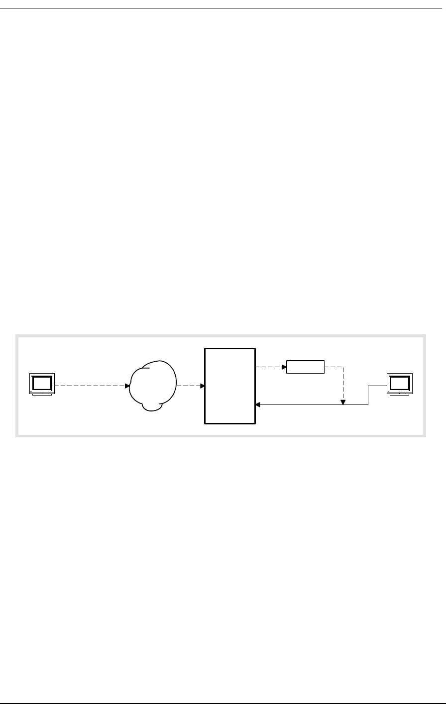
1.7.2.1 Local and Remote SNMP Management
The Access Bank II SNMP provides SNMP management through its Ethernet 10Base-T port. Remote
SNMP management is possible over either of the T1 lines within a V.35 user data segment, as shown
in Figure 1-1.
Figure 1-1: Local and Remote SNMP Management
1.7.2.2 SNMP Overview
SNMP is a complete, but simple, mechanism for network management. It works by exchanging infor-
mation between a Manager and an Agent. In this case, the Agent is inside the Access Bank II/SNMP.
The Manager is a Network Management Station (NMS), which is a computer with SNMP manage-
ment software such as HP OpenView® or Sun NetManager®.
The Agent stores the information in a Management Information Base (MIB), which contains items
such as the current status of the network interface, performance statistics, and alarms.
In general, SNMP is not concerned with controlling every feature of the many different network
objects. However, SNMP is flexible enough that it can support a wide variety of private enterprise
objects with predefined MIB data structures. The Access Bank II/SNMP uses the Bellcore® standard
MIB for T1 interfaces.
Manager operations include simple “get” and “set” commands to retrieve and update MIB data in the
Router
Access
Bank II
SNMP
SNMP
Manager
SNMP in
data stream
V.35
Ethernet
10Base-T
T1
Remote
Control
SNMP
Manager
Local
Control
Frame
or IP
Network
LAN

1-6 9/24/01
Agent. Normally, the Manager polls the Agent periodically to check traffic statistics. However, the
Manager can also set thresholds for traps. Traps specify network events and conditions for which the
Agent automatically sends a Telnet alarm message with trap data back to the Manager.
1.7.3 Command Line Interface
The Access Bank II SNMP comes with a built-in Command Line Interface. CLI provides complete
management of all Access Bank features through any VT-100 terminal or PC connected to the RS-
232 port, or through any Telnet terminal connected to the Ethernet 10Base-T port.
CLI works with a communications terminal, in which you type in text and press the carriage return
key to send the message to the host. The host then responds with a log-on message, and the CLI is
ready to use.
CLI is easy to use because the Access Bank II SNMP provides a list of menu options to choose from.
Furthermore, context sensitive help is available to guide you through the setup process. At any time,
you can type in a question mark (?) to obtain information about what to type next or what commands
are available. You can also type “help” after any command to get specific help with that command.
1.7.3.1 Local and Remote CLI Management
The Access Bank II SNMP provides CLI management through its RS-232 and Ethernet 10Base-T
ports, as shown in Figure 1-2 and Figure 1-3.
For RS-232 CLI control, just connect a PC or laptop computer to the RS-232 management port on the
Access Bank II/SNMP. Then use a VT-100 terminal emulation program such as Microsoft Hyper Ter-
minal®. (The default communications port settings are 9600, 8, 1, N.) Press the Escape key to initiate
the link. The Access Bank will return a log-on message. If a password is required, the Access Bank
will request that you enter a password. (Units shipped from the factory do not have a password
defined, but the user is encouraged to use passwords to prevent unauthorized use.) CLI can be used
from a remote site by connecting the RS-232 port to a modem and telephone line.
.
Figure 1-2: Local and Remote RS-232 CLI Management
Modem
Access
Bank II
SNMP
VT-100
Terminal
FXS
RS-232
T1
Modem Telephone
Network
Remote
Control
VT-100
Terminal
Local
Control
Local and Remote Network Management
9/24/01 1-7
Figure 1-3: Local and Remote Telnet CLI Management
For Telnet CLI management, you can use a Telnet TCP/IP communications program to access CLI
through the Ethernet management port. Remote Telnet CLI operation is available using Telnet over
Ethernet or using inband T1 via the V.35 data port.
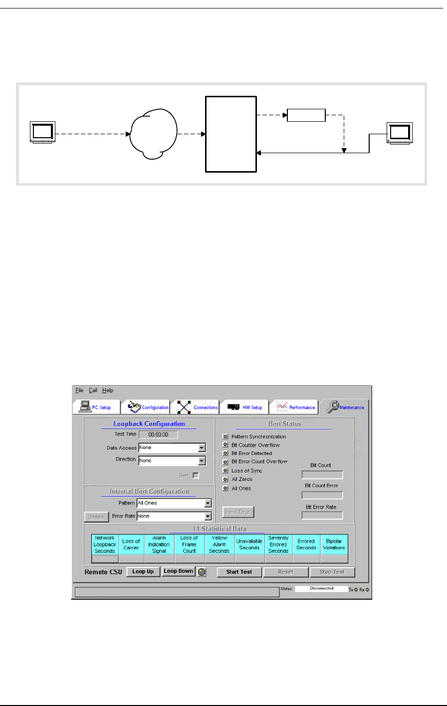
1.7.4 Windows-Based GUI Management Software
The Windows®-based GUI Management software (Figure 1-4) provides a graphical user interface
(GUI) that makes management as easy as clicking a mouse button. Pull-down menus and Index Tabs
make it easy to find just the function you’re looking for. CAC’s GUI Management software provides
convenient access to most features of the Access Bank II SNMP. For detailed software description,
see Access Bank II SNMP User Manual.
.
Figure 1-4: Carrier Access Corporation’s GUI Management Software
The GUI software follows a top-down hierarchy that organizes Access Bank management functions
into six basic groups. Index tabs at the top of the screen give quick access to:
Router
Access
Bank II
SNMP
Telnet
Terminal
Telnet in
data stream
V.35
Ethernet
10Base-T
T1
Remote
Control
Telnet
Terminal
Local
Control
Frame
or IP
Network
LAN
1-8 9/24/01
•PC Setup
• Configuration
• Connections
• Hardware Setup
• Performance Statistics
• Maintenance
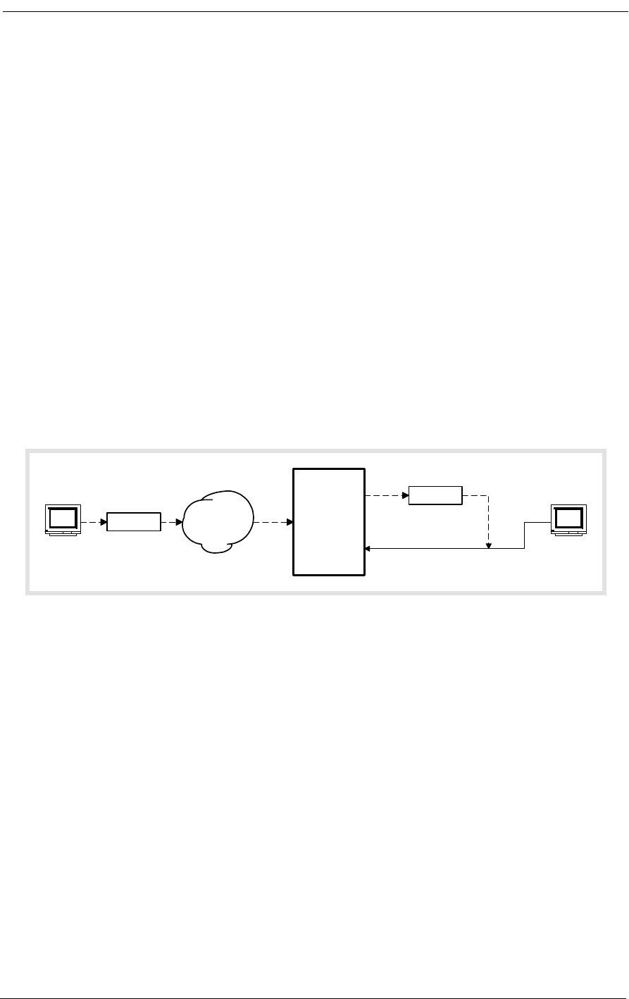
1.7.5 Local and Remote GUI Management
For configuration, monitoring, and testing purposes, each Access Bank II SNMP is shipped with
CAC’s Windows®-based GUI management software, backed by a full-featured system of context-
sensitive online help. Installed on a local 486 (or higher) IBM-compatible PC equipped with at least
16 MB RAM, Windows 95®, a keyboard and a mouse, this software program provides a convenient
user-friendly interface for configuring and monitoring the performance of the Access Bank II SNMP
via the RS-232 management port (Figure 1-5).
.
Figure 1-5: Local and Remote GUI Management
The GUI management software can also be installed on a remote Windows® PC for management
over a separate PSTN (Public Switched Telephone Network) analog line. In this application, the GUI
management software can also be used to poll the Access Bank II SNMP for remote alarms via an
external Hayes®-compatible modem attached to the RS-232 management port.
1.8 Design Philosophy
The Access Bank II SNMP is manufactured by CAC according to a design philosophy based on
solid-state overvoltage and overcurrent protection without the use of low-current fuses (<1 A) or very
high-wattage resistors. Thanks to this advanced new technology, the Access Bank II SNMP complies
fully with National Electrical Code and UL 1459 requirements for the safety of equipment attached to
telephone wiring without using any fuses, which dramatically improves its long-term reliability,
while greatly reducing equipment down time. As an added benefit, all items of equipment connected
to the Access Bank II SNMP are protected from transient network voltage or current surges.
Modem
Access
Bank II
SNMP
Windows
Computer
FXS
RS-232
T1
Modem Telephone
Network
Remote
Control
Windows
Computer
Local
Control

About This Chapter
9/24/01 2-1
Chapter 2
Product Description
Contents of This Chapter:
2.1 About This Chapter
This chapter describes the general physical characteristics and layout of the Access Bank II - SNMP,
including its:
• Dual RJ-48C Jacks for T1 Span 1 and Span 2
• V.35 and RS-232 Digital Interface Ports
• Power Source Connector
• Standard 25-pair RJ-21X Tip & Ring Telephony Connector
• T1 Span and System Setup DIP switches
• LED Test and Status Indicators
2.2 Physical Characteristics
The Access Bank II - SNMP consists of a painted sheet steel chassis housing, nickel-plated chassis
tray and removable back plate that accepts one (or two) 7.8 inch by 13.16 inch analog line interface
daughter card(s). These analog line interface channel cards slide into the rear of the unit along rails
that guide a 64-pin DIN connector on each card to mate with a matching connector on an internal
About This Chapter .................................... 1
Physical Characteristics ............................. 1
Control Panel Interface Connectors ........... 2
Control Panel DIP Switches ....................... 3
LED Test and Status Indicators ................. 3

2-2 9/24/01
Controller card. The Controller card measures approximately 4 inches by 16.25 inches and functions
as a Line Interface Unit (LIU) that integrates the two Channel Service Units (CSUs), the ringing gen-
erator, the ringback tone generator, and power converter functions. Separate Dual T1 and SNMP
daughter cards measuring 1.75 inches by 6.25 inches are each mounted on the Controller card using
support standoffs, plastic washers and screws. The Dual T1 daughter card is equipped with two stan-
dard RJ-48C 8-pin connector jacks for connecting to one (or two) T1 carrier network interface(s).
The SNMP daughter card is equipped with an RJ-45 modular jack for TCP/IP 10Base-T Ethernet
connection.
The Access Bank II - SNMP is 1.75 inches high, 17.75 inches deep, and 17 inches wide and, when
fully loaded with two analog line interface daughter cards, weighs approximately 14.5 pounds.
The Access Bank II - SNMP is designed to operate at an altitude between 0 and 10,000 feet above sea
level and within a temperature range from 32° to 104° F (0° to 40° C) and in environments with a rela-
tive humidity from 0 and 95%.
Note: For proper Access Bank II - SNMP operation outside the specified ranges,
the unit must be placed in an environmentally controlled enclosure.
2.3 Control Panel Interface Connectors
The Control Panel on the front of the chassis housing contains the following connectors and power
connection terminals shown in Figure 2-1:
• Dual T1 Span 1 and Span 2 line connection ports each equipped with standard RJ-48C 8-
pin connector jacks.
• V.35 DCE Data port equipped with a 26-pin standard D-type subminiature connector
(female) for high-speed digital Internet WAN connections up to 1.536 Mbps.
Note: An optional V.35 data cable is required to utilize the V.35 DCE data port.
• RS-232 Remote Management port equipped with a standard 26-pin D-type subminiature
connector (female) for connection to an external PC or Hayes-compatible modem for
local or remote configuration, management, and performance monitoring using the
Access Bank II - SNMP Remote Monitor MS Windows-based software interface or com-
mand line interface.
Note: An optional Dual Headed Data and Management Cable is required to connect
to the primary Management and secondary Data leads for simultaneous local or
remote management and asynchronous or synchronous data connections.

Control Panel DIP Switches
9/24/01 2-3
• Three-position DC power terminal input for connection to the 115 Vac to -48 Vdc Power
Converter Cube, or to a customer-supplied external -48 Vdc battery power source.
• Tip & Ring Analog Interface equipped with standard 25-pair Telephony Connector
(female) for connection to key systems, facsimile devices, modems and PBXs.
The ABII Control Panel is equipped with an interface connector for accessing the embedded SNMP
agent.
2.4 Control Panel DIP Switches
The Access Bank II - SNMP Control Panel also contains a 10-position T1 Span Setup DIP switch that
is used for individually configuring each of the two T1 network interfaces. There is also a 4-position
System Setup DIP switch for selecting between Local or Remote modes of management and activat-
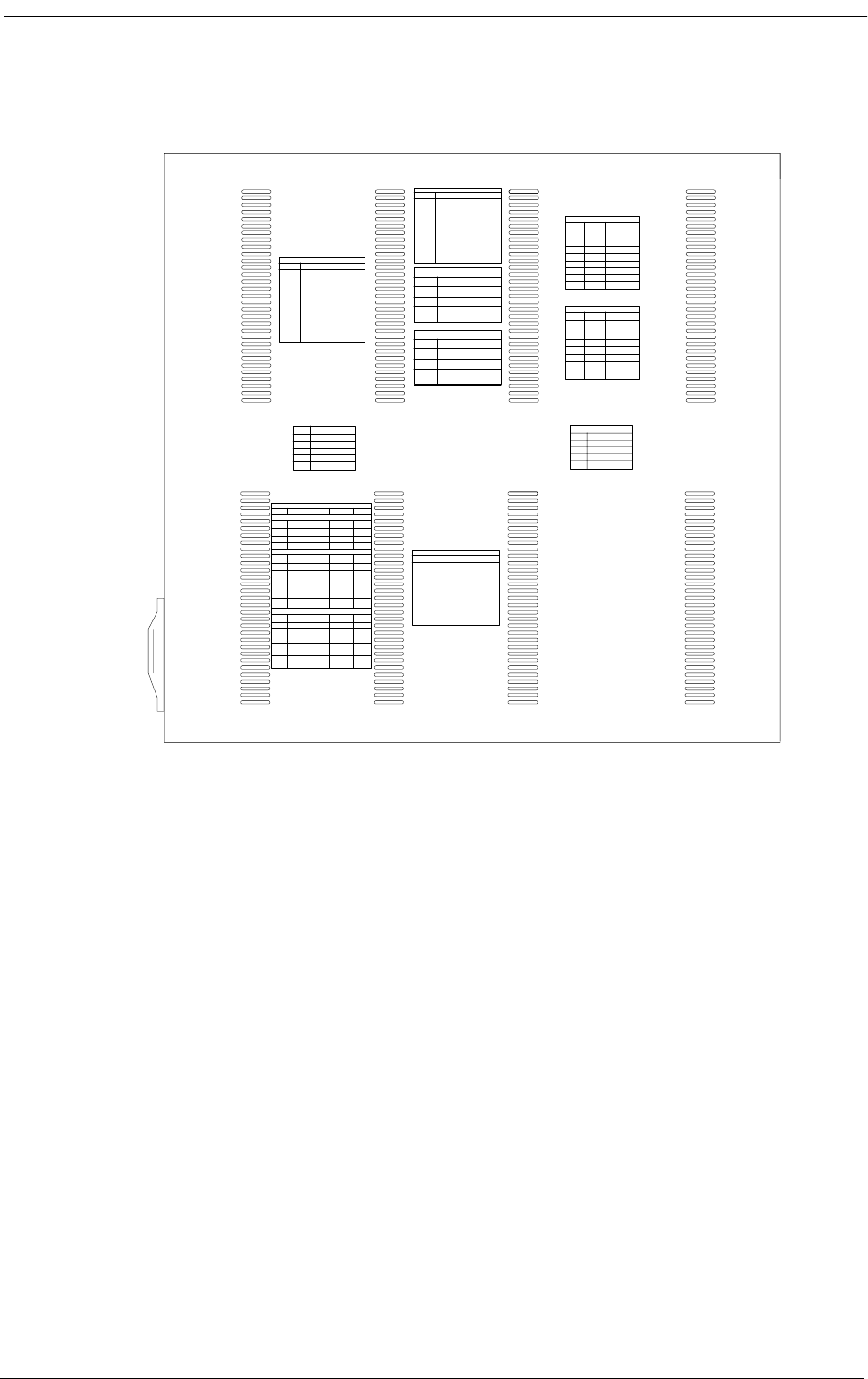
ing and deactivating alarm cut-off. The locations of these DIP switches are shown in Figure 2-1. As
an aid to setting up the these DIP switches, a convenient installation guide is silk screened onto the
chassis housing and reprinted here in Figure 2-2.
2.5 LED Test and Status Indicators
There are five LED indicators that display the current performance and test status of the dual T1
spans lines and V.35 digital interface. Figure 2-1 shows the locations of these LEDs on the Access
Bank II - SNMP front Control Panel. How to interpret the current state of each LED indicator is silk
screened onto the chassis housing and reprinted here in Figure 2-2.
Figure 2-1: Access Bank II - SNMP Control Panel
T1
Span 1
T1
Span 1
T1 Span Setup
Self Test 1
Network Loopback 1
T1 Framing 1
T1 Line Code 1
CSU On/Off 1
Self Test 2
Network Loopback 2
T1 Framing 2
T1 Line Code 2
CSU On/Off 2
System Setup
SNMP/TELNET
2-4 9/24/01
Figure 2-2: Access Bank II - SNMP Top Cover Installation Guide
Top View
T1 LEDs (PER SPAN)
STATE MEANING
OFF Loss of T1 signal, no pulses
received
GREEN Nodal Switch is in frame with
frame bit error rate <10E -5
FLASHING Nodal Switch is in frame, but
GREEN frame bit error rate exceeds 10E-5
RED AIS (unframed all ones)
received from the T1 line
FLASHING Nodal Switch is not framed to
RED the T1 line but no AIS is received
YELLOW Yellow alarm received from the T1 line
FLASHING BPV errors received on the T1 line
YELLOW that are not due to B8ZS line coding
V.35 STATUS LED
STATE MEANING
OFF No T1 channels assigned to V.35
port
GREEN CD and RTS active. T1 channels
assigned and operable
FLASHING V.35 in loopback to equipment
GREEN
RED CD is inactive because assigned
T1 is inoperable
YELLOW CD active RTS inactive
FLASHING V.35 in loopback to T1 line
YELLOW
T1 TEST LEDs (PER SPAN)
STATE MEANING
GREEN Normal operation. Trunk processing,
self test, and network loopback
inactive
FLASHING T1 self test local loopback
GREEN passed
RED T1 self test local loopback
failed
YELLOW Channels held in trunk processing
for this T1
FLASHING Network loopback active for this
YELLOW T1
T1 JACK R48CPIN ASSIGNMENT
1 R1 - Receive ring from T1 line
2 T1 - Receive tip from T1 line
4 R - Transmit ring to T1 line
5 T - Transmit tip to T1 line
7&8 Ground for T1 cable shields
NODAL SWITCH CONTROL SWITCHES
SWITCH FUNCTION OFF ON
SYSTEM SETUP
1 local/remote local remote
2 alarm cutoff enable alarm disable alarm
3 Option 1
4 Option 2
T1 SPAN 1 SETUP
1 Self test 1 off on
2 Network loopback 1 off on
3 T1 framing 1 Superframe Extended
(SF) (also superframe
called D4) (ESF)
4 T1 line coding 1 Alternative B8ZS
Mark
Inversion (AMI)
5 CSU on/off 1 Detect loop Reject CSU
code (normal) loopcode
T1 SPAN 2 SETUP
6 Self test 2 Off On
7 Network loopback 2 Off On
8 T1 framing 2 Superframe Extended
(SF) (also superframe
called D4) (ESF)
9 T1 line coding 2 Alternative B8ZS
Mark
Inversion (AMI)
10 CSU on/off 2 Detect loop Reject CSU
code (normal) loopcode
NODAL SWITCH ANALOG LEVELS
SWITCH FUNCTION LEVEL
Six switches Transmit = Off adds loss
per channel Analog to T1
Receive = All switches off =
T1 to analog 0 dB
1 Receive -2 dB Off = 2 dB lower
2 Receive -3 dB Off = 3 dB lower
3 Receive -4 dB Off = 4 dB lower
4 Transmit -2 dB Off = 2 dB lower
5 Transmit -3 dB Off = 3 dB lower
6 Transmit -4 dB Off = 4 dB lower
NODAL SWITCH ANALOG SIGNALING
SWITCH LABEL FUNCTION
Four Four switches Off adds loss
switches set card sig-
per card naling options Consult manual for
for all 12 chan signaling option settings
per voice card type
1 Option A Off = normal FXS
2 Option B Off = normal FXS
3 Option C Off = normal FXS
4 Trunk proces- When TP or test:
sing (TP) On = loop busy
Busy/Idle Off = loop idle
BACKPANEL CHANNEL LEDs
COLOR PER CHANNEL FUNCTION
OFF Idle (FXS ground start , tip open
GREEN Incoming call (FXS loop start
RED Outgoing call
YELLOW Answer (taking) condition
Tip & Ring
Connector
10 BASE T ACTIVITY LED
STATE MEANING
OFF No data RX/TX
GREEN RX/TX Data
RED Collision detected
10 BASE T LINK LED
STATE MEANING
OFF No signal received
GREEN Validate connection

About This Chapter
9/24/01 3-1
Chapter 3
Technical Specifications
Contents of This Chapter:
3.1 About This Chapter
This chapter summarizes the technical specifications of the Access Bank II - SNMP including its:
• Dual T1 network interfaces
• Channel Services Units (CSUs)
• Digital data ports
• Analog line interface channel cards
• Network management capabilities
•Alarms
• Standards compliance
•Powering
• Environmental parameters
• Physical Dimensions
About This Chapter .................................... 1 4-Wire E&M/TO Voice Card .................... 4
Dual T1 Network Line Interfaces .............. 1 Network Management ............................. 4
Line Codes ................................................ 2 Alarms ..................................................... 5
Framing ..................................................... 2 Control Panel I/O Connectors ................. 5
Clock Source ............................................ 2 Standards Compliance ............................ 5
T1-to-T1 Delay .......................................... 2 Power ...................................................... 6
T1 Channel Service Units (CSUs) ............ 2 Environmental ......................................... 6
Digital Data Ports ...................................... 3 Physical Dimensions ............................... 6
Analog Line Interfaces .............................. 3 Installation ............................................... 6
FXO/DPT Voice Card 4

3-2 9/24/01
3.2 Dual T1 Network Line Interfaces
3.2.1 Total Bandwidth
• 3.072 Mbps
3.2.2 DS-1 Output Signals
• Pulse amplitude: 2.0 V to 3.6 V ±60 Hz variations
• Line Rate: 1.544 Mbps ±50 bps
• Format: T1 type bipolar (except where intentional BPVs are introduced by B8ZS line
coding)
3.3 Line Codes
• AMI or B8ZS and line code conversions between T1 lines
3.4 Framing
• D4 (Superframe) or ESF and framing format conversions between T1 lines
3.5 Clock Source
• Loop Timing: Selectively recovered from incoming T1 Span 1 or Span 2
• Master Clock: Internal Enhanced Stratum 4E Crystal Oscillator ±32 ppm accuracy)
3.6 T1-to-T1 Delay
• Latency: 3 frames maximum (0.375 ms)
3.7 T1 Channel Service Units (CSUs)
• Integrated intelligent CSUs support all standard diagnostic functions and DS-1 or DSX-1
signal levels from 0 to -30 dB
• Software programmable Line Build Out (LBO): 0 dB/DSX (0’-133’) (default), -7.5 dB, -
15 dB, -22.5 dB, DSX (133’-266’), DSX (266’-399’), DSX (399’-533’), DSX (533’-
655’)
• AT&T 54016 Maintenance Messages or T1.403 Performance Report Messages (PRMs)
through 4 Kbps ESF Facility Data Link (FDL)

Digital Data Ports
9/24/01 3-3
• Standard inband and out-of-band CSU network loopbacks
• Internal BER tester with selectable industry standard QRSS test patterns
3.8 Digital Data Ports
3.8.1 V.35 Serial Port
• Synchronous V.35 data from 56 Kbps to 1.536 Mbps in Nx56 Kbps or Nx64 Kbps steps,
all rates.
• Built-in V.54 loopback code generation and detection for BERT
3.8.2 RS-232 Remote Management/Data Port
• Asynchronous point-to-point RS-232 data at 9.6, 19.2, 28.8, 38.4, and 57.6 Kbps
• Synchronous RS-232 data at 56 or 64 Kbps
3.9 Analog Line Interfaces
• FXS Ground Start/Loop Start voice card
• Battery reversal FXS/DPO voice card
• FXO/DPT voice card
• 4-wire E&M/TO voice card
• Patent-pending automatic analog impedance adjustment adapts to various modems and
line lengths
• “Hot-swappable” slide-in channel cards
• 28.8 Kbps V.34 modem compatibility
3.10 FXS Voice Card
• Software-defined functions: E&M Immediate/Wink start to Loop start/ground start con-
version with Ringback Tone for carrier services sucn as Megacom®, Flexpath®, DSS®,
VPN®, VNET®, etc.
• Wink Delay for advanced ANI/DNIS 800 number services and Direct Inward Dial (DID)
conversion
• Private Line Automatic Ringdown (PLAR) with Ringback Tone
• Calling Party (Forward) Disconnect provides two-second current interruption to discon-
nect Answering Devices and Modems. (Only available with E&M Immediate software-

3-4 9/24/01
defined signaling options.)
• DC Loop Range: 1200 ohms (3 miles on 24 AWG + 300 ohms telephone)
• Loop Feed: Nominal -48 Vdc with 30 mA current limit
• Separate Transmit/Receive Gain Settings on a Per Channel Basis
• All-channel simultaneous ringing power: 85 Vrms at 20 Hz
• Built-in ringback tones
• Battery Reversal FXS/DPO Voice Card
• FXS Loop Start with Battery Reversal or Dial Pulse Originating (DPO) functionality per
card
• Optional Cadenced Ringback Tone (two-seconds on, four seconds off) to the T1 line dur-
ing incoming calls, synchronized to the ringing voltage present on the loop
• Optional Cadenced Ringing Voltage applied to CPE loop during an incoming call
• Supports CLASS® services, including Caller ID
3.11 FXO/DPT Voice Card
• FXO Loop-Start/Ground-Start terminations per channel
• Dial Pulse Termination (DPT) functionality per card
• Separate transmit and receive gain settings per channel
• DID and DNIS carrier services
• CLASS® services, including distinctive ringing and caller ID
3.12 4-Wire E&M/TO Voice Card
• Optioned with on-board jumpers to support E&M signaling types I, II, IV, or V, for each
channel
• Supports Transmission Only (TO) for dedicated modems, radio/paging systems, etc.
• Separate gain and loss settings from +10 dB to -21 dB for both transmit and receive paths
for each channel
• Maximum analog transmission level of +9.5 dBm
3.13 Network Management
• RS-232 Primary Management Port, Cable, Command Line Interface, and MS Windows-
based Remote Monitor Graphical User Interface (GUI) software program included with

Alarms
9/24/01 3-5
Access Bank II - SNMP purchase.
• Control Panel T1 test switches and status LEDs
• Rear panel voice channel option switches, test switches, and status LEDs
• Embedded SNMP agent for performance monitoring and configuration of T1, V.35, and
RS-232 data ports
3.14 Alarms
• Alarm dial-out notification over external modem attached to RS-232 Management port
• External alarm contact for visible/audible alarms using pair 25 of RJ-21X standard tele-
phony connector on Control Panel
• Control Panel Alarm Cut-Off (ACO) Switch
3.15 Control Panel I/O Connectors
• T1 Span 1 and Span 2: Standard RJ-48C 8-pin jacks
• V.35 DCE Data Port: 26-pin D-type subminiature V.35 connector (female)
• Management Interfaces:
• Management: Primary logical RS-232 port for connection to external Hayes-compat-
ible modem or to IBM-PC (or compatible) with MS Windows Hyperterm (or com-
patible), and MS Windows-based Remote Monitor software program installed
• Data: Secondary logical RS-232 data port
• Connector: 26-pin D-type subminiature EIA/TIA RS-232 connector (female)
• Adapter Cable: Dual RS-232 Management Cable for simultaneous connection to
Data and Management RS-232 interface lead
• SNMP RJ-45 jack for 10Base-T Ethernet TCP/IP connection.
• Tip & Ring Interface:Standard 25-pair RJ-21X Telephony Connector (female)
3.16 Standards Compliance
• ANSI/TIA T1.403-1995 One-second Performance Report Messages (PRMs)
• ANSI/TIA 464-A-89 PBX Switching Equipment for Voice Band Applications
• AT&T 54016 Maintenance Messages on the 4 Kbps ESF Facility Data Link (FDL)
• AT&T 62411 Enhanced Stratum 4 Timing Requirements for T1 CPE
• AT&T 62411 Standard T1 Pulse Mask Characteristics
• Bellcore TR-TSY-000057 for Digital Loop Carrier Systems

3-6 9/24/01
• Bellcore TR-NWT-000499 Generic Transport Requirements
• FCC Part 15, Class A for Radiated Emissions Control
• FCC Part 68, CS-03 for T1 CSU Interface, Network Protection, Line Balance, REN
• National Electrical Code 1996 Safety Requirements
• NRTL Safety Listed: UL 1459, 2nd Edition concerning Minimum 600 Vrms Lightning
Protection, CSA
• IEEE 802.3 10baseT interface
• EIA RS-232-D
• RFC 1213, 1573, 1406, 1659
3.17 Power
• Control Panel DC Power Input Terminal: -48 Vdc with 1 Amp circuit breaker from local
battery
• Standard Power Source: 115 Vac to -48 Vdc Power Converter Cube
• Optional Power Source: 220 Vac to -48 Vdc Power Converter Cube
• Input voltage: -42 to -60 Vdc at 1 Amp (constant current power source)
3.18 Environmental
• Altitude: 0 to 10,000’ (0 to 3,048 m)
• Humidity: 0 to 95%
• Temperature Range: 32º to 104º F (0º to 40º C)
• Thermal Protection: Automatic cut-off at 104ºF (40º C) until lowered below limit
3.18.1 Physical Dimensions
• Height: 1.75 inches (4.45 cm)
• Depth: 17.75 inches (45.1 cm)
• Width: 17 inches (43.2 cm)
• Weight: 14.5 Lbs (6.6 Kg) fully loaded

Installation
9/24/01 3-7
3.19 Installation
• Wall-mount, surface-mount, or standard EIA 19-inch rack-mount using supplied adapter
brackets and screws
• Seven foot standard rack accepts up to 24 Access Bank II - SNMP units

3-8 9/24/01

About This Chapter
9/24/01 4-1
Chapter 4
Physical Installation
Contents of This Chapter:
4.1 About This Chapter
This chapter describes how to physically install the Access Bank II - SNMP and provides procedures
for:
• Checking items required for installation
• Mounting the Access Bank II - SNMP chassis
• Mounting the Power Converter
4.2 Installation Check List
Caution: When installing the Access Bank II - SNMP, be sure to observe
standard safety procedures for working with hazardous electrical equipment.
This product is shipped as a complete package including the Access Bank II - SNMP equipped (per
About This Chapter .................................... 1
Installation Check List ................................ 1
Chassis Mounting ...................................... 5
Wall Mounting ............................................ 6
Rack Mounting ........................................... 6
Surface Mounting ....................................... 7
Mounting the Power Converter .................. 7
!

4-2 9/24/01
order) with 0, 1, or 2 analog interface cards, Access Bank II - SNMP Remote Monitor software for
the PC, and a power conversion cube. The package also contains one modular Category 5 T1 network
interface cable, a 25-pin local management cable, a 25-pin to 25-pin null modem adapter, a 25-pin to
9-pin straight adapter, and “rabbit ear” adapter brackets with screws for wall or 19-inch rack-mount-
ing. You will also find enclosed a copy of this manual along with a product warranty registration
card.
• Check the contents of the shipping carton against the Packing Materials List.
• Inspect the Access Bank II - SNMP for signs of damage, and report any damages to the
shipper.
• Retain all packaging materials in case you need to ship or relocate the unit.
Table 4-1: Access Bank II - SNMP Packing Materials List
Description CAC Part No.
Items Included With Access Bank II - SNMP Purchase
Access Bank II - SNMP equipped according to customer order with 0,
1 or 2 line interface voice cards
Access Bank II - SNMP Remote Monitor MS Windows−based Soft-
ware for the PC (5 Disk Set) 019-0035 Release 2.0
“Rabbit Ear” wall/rack mounting adapter brackets (4) with screws 004-0015
115Vac/60Hz to -48Vdc Power Conversion Cube with 5-foot 16 AWG
grounded wall plug power cord and alternate 8-foot DC connector
cord
003-0016r
One (1) 10-foot modular category 5 T1 network interface cable, RJ-
48C to RJ-48C, for connecting Access Bank II - SNMP to T1 network,
or to a PBX D&I port.
005-0009
RS-232 local management cable (10 ft) for managing the Access Bank
II - SNMP using a directly attached computer through the RS-232
management port.
005-0003-DCE-MF-10
25-pin male to 25-pin male null modem adapter (10 ft) for connecting
Access Bank II - SNMP to an external modem through either the local
mgt. cable or the optional dual RS-232 data and mgt. cable.
005-0002-25M-25M-Null
Modem
RS-232 25-pin male to 9-pin female straight adapter (10 ft) for
directly connecting the Access Bank II - SNMP to a 9-pin computer
device through either the local management cable or the optional dual
RS-232 management cable.
005-0007-25M-9F-
Straight
Access Bank II - SNMP Installation and User’s Manual 002-0071
Warranty registration card AB-II-WC
Optional Items
Additional category 5 T1 network IF cables, RJ-48C to RJ-48C, 10 ft 005-0009

Chassis Mounting
9/24/01 4-3
In addition, you will need one or more of the following items:
• A standard 25-pair telephone cable with “D” style 50-pin male connector to connect the
Access Bank II - SNMP to your punch-down block or RJ-11 “Harmonica.”
• If you are wall-mounting the Power Converter Cube, you will need four fasteners appro-
priate for mounting a seven-pound object.
4.3 Chassis Mounting
The Access Bank II - SNMP can be wall-mounted, rack-mounted, or surface-mounted. Prior to
mounting the Access Bank II - SNMP chassis, ensure that the installation site meets the following cri-
teria:
• Adequate clearance for access to control panel DIP switches, cable routing, and ventila-
tion. Leave at least 18 inches behind the back plate for maintenance and accessing the
slide-in voice cards.
• Because the cables on the power conversion cube total 13 feet in length, there should be
a properly grounded, 110 VAC power outlet within 10 feet of the Access Bank II - SNMP
Control Panel.
• A stable environment, clean and free from extremes of temperature, shock, vibration and
EMI, with a relative humidity between 0 and 95%.
• An ambient temperature that stays below 40º C (104º F).
Dual RS-232 data and magagement cable (10 ft) for connection to a
router, computer, statistical multiplexer, SNA cluster controller, or
SCADA equipment. This cable supports both synchronous operation
at 56 or 64 Kbps, and asynchronous operation at 9.6, 19.2, 28.8, 38.4,
and 57.6 Kbps.
005-0001 - DCE - MFF -
10’ - 10’
V.35 data cable - 10 ft 005-0008-DCE-MM-10’
V.35 data cable - 25 ft 005-0009-DCE-MM-25’
V.35 data cable - 50 ft 005-0010-DCE-MM-50’
19” heavy duty rack mounting brackets (2) with sixteen (16) 6-32 x 3/
8” phillips pan-head screws 004-0041
23” heavy duty rack mounting brackets (2) with sixteen (16) 6-32 x 3/
8” phillips pan-head screws 004-0113
220Vac/50Hz to -48Vdc Power Conversion Cube for international
applications with custom wall plug adapter AB-220Power

4-4 9/24/01
Caution: If the operating temperature rises above the 40º C limit an internal
thermal protection device will shut off the Access Bank II - SNMP. When the
temperature is reduced below this threshold, the Access Bank II - SNMP
restarts.
• An installation site below 10,000 feet (3,048 m).
• For operation outside these ranges, the Access Bank II - SNMP must be placed in an
environmentally controlled enclosure.
Caution: When you mount the chassis, do not allow the Access Bank II -
SNMP to remain in direct contact with any combustible surface.
4.4 Wall Mounting
The adapter brackets attached to the Access Bank II - SNMP are positioned at shipment for wall-
mounting. To wall-mount the unit:
1. Select a location that meets the criteria specified above. Leave at least 1/2 inch clearance
below the chassis for ventilation. Leave at least 6 inches in front of the Access Bank II -
SNMP Control Panel for access to its switches and LEDs and at least 18 inches behind the
back plate for maintenance.
2. To create a 3/4 inch offset between the Access Bank II - SNMP chassis and the wall surface
for better ventilation, mount a 3/4 inch thick piece of plywood (at least 20 inches vertically
by 14 inches horizontally) on the wall using fasteners appropriate for mounting a heavy
object (see Figure 4-1).
3. Mount the Access Bank II - SNMP chassis to the plywood with eight #8 x 3/4” pan-head (or
larger) wood screws (Figure 4-1).
4.5 Rack Mounting
The Access Bank II - SNMP can be rack-mounted using several different methods. The small adapter
brackets shipped with the unit can be used to mount the unit in a standard 19” rack with a typical five-
inch offset. Using the recommended heavy-duty brackets, you can mount the Access Bank II - SNMP
in either a 19” or 23” rack with a custom offset.
!
!

Surface Mounting
9/24/01 4-5
4.5.1 Rack Mounting with Brackets Shipped with Unit
To mount the Access Bank II - SNMP in a standard EIA 19-inch Telco equipment rack using the
included adapter brackets:
1. Remove the two front adapter brackets, rotate them 90 degrees and re-attach the brackets so
they face toward the unit back plate (Figure 4-2). This creates a standard five-inch offset
mounting typical of telecommunications equipment.
2. Select an appropriate location in the rack with at least 1 3/4 inches of clearance above and
below the chassis for ventilation. Also ensure that there is at least 6 inches in front of the
Control Panel for access to its controls and DIP switches, and at least 18 inches behind the
back plate for maintenance.
3. Mount the chassis using 10-32 x 3/4” machine screws appropriate for a Telco rack (Figure 4-
3).
Note: The optional heavy-duty rack mounting brackets (see Figure 4-4) can
significantly increase static strength and provide a custom front-to-back offset when
mounting the units on either 19” or 23” racks (see Figure 4-3).
4.5.2 Mounting with Heavy-Duty Brackets
1. Remove the four small front adapter brackets from the Access Bank II - SNMP.
2. Attach the heavy-duty brackets to the Access Bank II - SNMP using the screws included in
the heavy-duty bracket kit (see Figure 4-3).
3. Select an appropriate location in the rack with at least 1 3/4 inches of clearance above and
below the chassis for ventilation. Also ensure that there is at least 6 inches in front of the
Control Panel for access to its controls and DIP switches, and at least 18 inches behind the
back plate for maintenance.
4. Mount the chassis on the rack using 10-32 x 3/4” machine screws appropriate for a Telco
rack (Figure 4-3).
4.6 Surface Mounting
To surface-mount the Access Bank II - SNMP as a desktop stand-alone, simply place it on a flat, sta-
ble, non-combustible surface with at least 1/2 inch ventilation clearance below the unit. Leave at least
6 inches in front, and 18 inches in back of the chassis for ventilation and access to its controls. Leave
at least 3/4” above the chassis for required ventilation.
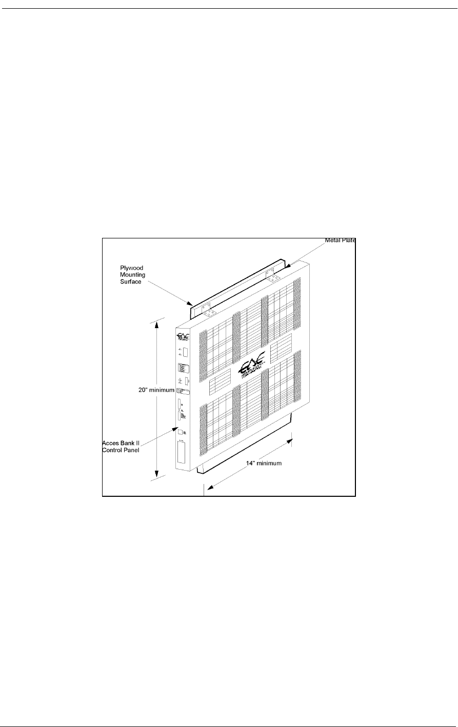
4-6 9/24/01
4.7 Mounting the Power Converter
The Access Bank II - SNMP is normally shipped for US operation with a 115 Vac to -48 Vdc power
conversion cube. This cube includes both a 5-foot grounded AC power cord and a 8-foot three-posi-
tion DC power cable. The Power Converter Cube has four mounting holes for attaching the unit to a
wall or other flat surface. To mount the Power Converter Cube on a nearby wall, locate the converter
within 7 feet of the Access Bank II - SNMP front Control Panel and use screws or anchors appropri-
ate to the mounting surface. If you are wall mounting the power conversion cube on the same ¾”
thick plywood sheet as the Access Bank II - SNMP, the dimensions of the board will have to be at
least 25” by 14”. Wire tie-downs can be used to keep stray wires to a minimum, but be careful not to
damage the wiring in any way.
Figure 4-1: Wall-Mounting the Access Bank II - SNMP

Mounting the Power Converter
9/24/01 4-7
Figure 4-2: Rack Mounting on a 19” Rack Using Small Brackets
1. Remove, rotate, and
re-attach the two front
mounting brackets as
shown.
2. Mount the unit to the
rack with four screws.
CAUTION: Do not use the
rear mounting position to
mount the unit except to a
second rail for additional
sup p o rt.
St a n d a rd EI A
19" Rack
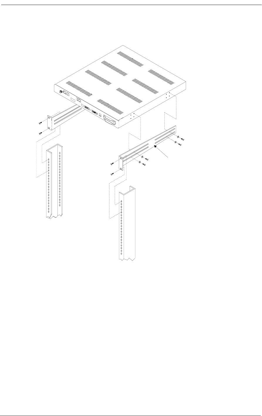
4-8 9/24/01
Figure 4-3: Rack Mounting on a 19” Rack Using Heavy-Duty Brackets
1. Remove the small
brackets from the unit.
2. Fasten heavy-duty
brackets to unit as
shown.
3. Mount the unit on the
standard rack using four
10-32 x 3/4" machine
sc rews.
4. Adjust the offset by sliding
the screws in the bracket
slots, then tighten the screws.
NOTE: To mount units in standard
EIA 23" racks, use heavy-duty
bracket CAC PN 004-0113.
19" Heavy-duty mounting
brackets CAC PN 004-004
1

Mounting the Power Converter
9/24/01 4-9
Figure 4-4: Optional Heavy Duty Brackets
2.8"
15"
2.8"
15"
Part Number 004-
0113 23" Rack
Mounting Bracket
Part Number 004-
0041 19" Rack
Mounting Bracket

4-10 9/24/01

About This Chapter
9/24/01 5-1
Chapter 5
Electrical Installation
Contents of This Chapter:
5.1 About This Chapter
This chapter describes how to install the communication interface and power connectors on the
Access Bank II SNMP Control Panel and includes procedures for:
• Enabling the internal lithium battery.
• Connecting the voice circuits to the punch-down block.
• Connecting the T1 lines.
• Connecting the RS-232 Management Port.
• Connecting the V.35 DCE data port.
• Using Adapters.
• Connecting the Power and Ground.
• Bringing the Access Bank II SNMP on line.
About This Chapter .................................... 1
.Installing Cables and Adapters ................. 2
Interface and Power Connectors ............... 4
Connecting the Voice Circuits .................... 5
Connecting the Dual T1 Lines ................... 6
V.35 DCE Data Port Connections .............. 7
RS-232 Management ............................... 12
Connecting the Power and Ground ......... 15

5-2 9/24/01
5.2 Installing Cables and Adapters
After mounting the Access Bank II SNMP chassis and power converter, the next step is connecting
the various voice and data interfaces and the power connector using the standard and optional cables
and adapters listed below in Table 5-1. Table 5-1 shows where the various T1, V.35 and RS-232 inter-
face and power connector are located on the Access Bank II SNMP front Control Panel.
The Access Bank II SNMP shipping package contains one modular category 5 T1 network interface
cable, a 25-pin local management cable, a 25-pin to 25-pin null modem adapter, and a 25-pin to 9-pin
straight adapter. Additional optional category 5 T1 network interface cables can be ordered separately
from CAC. Optional V.35 data cables are also available from CAC.
Table 5-1: Standard and Optional Access Bank II SNMP Cables and Adapters
Part
Number Cable
Length Application Connectors
005-0009 10 foot,
3.05 m T1 Network Cable for connecting the
Access Bank II SNMP to the T1 network, or
optionally to a PBX D&I port. One of these
cables is included with each Access Bank II
SNMP purchase. Additional T1 Network
Cables must be ordered separately.
RJ-48C to RJ-48C
005-0003-
DCE-MF-
10’
10 foot,
3.05 m RS-232 Local Management Cable for man-
aging the Access Bank II SNMP using a
directly attached computer through the RS-
232 Management Port. This cable is
included with each Access Bank II SNMP
purchase.
Fine Pitch D-Sub-26
Male to DCE DB-25
Female
005-0002-
25M-
25M-Null
Modem
N/A RS-232 25-Pin Male to 25-Pin Male Null
Modem Adapter for connecting the Access
Bank II SNMP to an external modem
through either the included Local Manage-
ment Cable. This adapter is included with
each Access Bank II SNMP purchase.
DCE DB-25 Male to
DTE DB-25 Male
005-0007-
25M-9F-
Straight
N/A RS-232 25-Pin Male to 9-Pin Female
Straight Adapter for directly connecting the
Access Bank II SNMP to a 9-pin computer
device through either the included Local
Management Cable. This adapter is
included with each Access Bank II SNMP
purchase.
DCE DB-25 Male to
DTE DB-9 Female
005-0008-
DCE-
MM-10’
10 foot,
3.05 m Ten-foot V.35 Data Cable for connecting a
router or other digital device to a T1 net-
work using the Access Bank II SNMP’s
V.35 DCE data port, accommodating high-
speed transfers up to 1.536 Mbps. This cable
is optional and must be ordered separately.
Fine Pitch D-Sub-26
Male to DCE V.35
Male

Access Bank II SNMP Control Panel Interface and Power Connectors
9/24/01 5-3
5.3 Access Bank II SNMP Control Panel Interface and
Power Connectors
Figure 5-1: Interface and Power Connectors on the Access Bank II SNMP Control Panel.
5.3.1 RJ-48C Jacks for T1 Span 1 and Span 2
One (or two) 10-foot modular Category 5 T1 Network Interface Cables are used to connect the RJ-
48C 8-pin connectors to the T1 carrier network RJ-48C jack(s).
5.3.2 SNMP Connector
The Access Bank II SNMP is equipped with an RJ-45 jack for accessing an embedded SNMP agent
via a customer provided cable.
5.3.3 V.35 DCE Data Port Connector
The optional CAC V.35 Data Cable (10’, 25’ or 50’) with a micro-D 26-pin (male) to 34-pin Win-
chester connector (male) connects this 26-pin V.35 DCE data interface connector (female) to cus-
tomer premise DTE.
5.3.4 DC Power Connector Input
Power connections are made to the DC Power Connector Input with a three-position removable wir-
ing connector on the 8-foot DC power cord from the 115 Vac to -48 Vdc Power Conversion Cube.
005-0009-
DCE-
MM-25’
25 foot,
7.62 m Twenty-five-foot V.35 Data Cable for con-
necting a router or other digital device to a
T1 network using the Access Bank II
SNMP’s V.35 DCE data port, accommodat-
ing high-speed transfers up to 1.536 Mbps.
This cable is optional and must be ordered
separately.
Fine Pitch D-Sub-26
Male to DCE V.35
Male
005-0010-
DCE-
MM-50’
50 foot,
15.24 m Fifty-foot V.35 Data Cable for connecting a
router or other digital device to a T1 net-
work using the Access Bank II SNMP’s
V.35 DCE data port, accommodating high-
speed transfers up to 1.536 Mbps. This cable
is optional and must be ordered separately.
Fine Pitch D-Sub-26
Male to DCE V.35
Male
T1
Span 1
T1
Span 1
T1 Span Setup
Self Test 1
Network Loopback 1
T1 Framing 1
T1 Line Code 1
CSU On/Off 1
Self Test 2
Network Loopback 2
T1 Framing 2
T1 Line Code 2
CSU On/Off 2
System Setup
SNMP/TELNET

5-4 9/24/01
5.3.5 Tip & Ring Jack (female)
Tip & Ring connections are made at this connector with an standard 25-pair telephone cable, which
also connects to the punch-down block or RJ-11 “Harmonica.”
Note: 4-wire E&M 12-channel voice card requires optional cables to connect to
the punch-down block. These cables eliminate the use of the front panel RJ-21X Tip
& Ring telephone connector.
5.4 Connecting the Voice Circuits
Voice circuit connections are made at the 50-pin Amphenol jack labeled Tip & Ring on the Access
Bank II SNMP Control Panel (see Figure 5-1). You will need a standard 25-pair telephone cable with
RJ-21X wiring and a D-type mating connector at the Access Bank II SNMP end. The other end con-
nects to either a punch down block or an RJ-11 “Harmonica” for interfacing to analog telephony
equipment.
To connect the voice circuits:
1. Connect the telephone cable to the punch-down block or RJ-11 “Harmonica.”
2. Route the cable to the Access Bank II SNMP Control Panel.
3. Remove any screws in the D-type connector that may prevent a flush connection with the Tip
& Ring jack.
4. Connect the D-type mating connector to the Tip & Ring connector on the Control Panel.
5. Cinch down the attached Velcro strap to retain the connectors.
6. Use the cable tie down on the unit and elsewhere to avoid accidental disconnection.
Note: If you are connecting an external alarm, note in Table 5-2 that pair 25 of the
voice drop cable provides a connection to a set of normally open relay contacts (150
Vrms, 150 mA maximum load) that close when the Access Bank II SNMP enters an
alarm state. For more information on external alarm events, see the Remote Monitor
section of this manual and the separate Remote Monitor User’s Guide.
Table 5-2 defines the pin functions on the 50-pin Amphenol-type Tip & Ring jack.

Connecting the Dual T1 Lines
9/24/01 5-5
Table 5-2: 50-Pin Tip & Ring Jack
5.5 Connecting the Dual T1 Lines
5.5.1 Customer Premises Installations
Connections to the T1 network interfaces are made at the RJ-48C 8-pin modular jacks on the Access
Bank II SNMP Control Panel (see Figure 5-1) using one (or two) 10-foot Category 5 T1 cable(s).
Note: Only one T1 network interface cable is provided with each unit. Additional
cables (P/N 005-0009) are available from distributors or dealers of CAC products.
The pin assignments for the RJ-48C jacks are defined in Table 5-3.
Table 5-3: T1 Line Interface on RJ-48C—T1 Modular 8-Pin Jack
For a customer premise installation, the primary T1 Span 1 and secondary T1 Span 2 network inter-
faces are cabled to carrier T1 demarcation points on the customer premises. To connect these cables,
plug either end into the RJ-48C connector of the desired T1 network interface and the other end into
the RJ-48C jack at the carrier T1 demarcation point jack.
Pair Pin Location Function
126
1Tip Channel 1
Ring Channel 1
227
2Tip Channel 2
Ring Channel 2
↓↓↓
24 49
24 Tip Channel 24
Ring Channel 24
25 50
25 Alarm Tip Channel 25
Alarm Ring Channel 25
Pin Number Signal Signal Direction
1 Receive Ring From DS1 Network
2 Receive Tip From DS1 Network
3 No connection
4 Transmit Ring To DS1 Network
5 Transmit Tip To DS1 Network
6 No connection
7 Receive Ground
8 Transmit Ground

5-6 9/24/01
5.5.2 ABAM 600 T1 Cable
Table 5-4 defines the characteristics of shielded 22 AWG ABAM 600 T1 cable. Shielded ABAM 600
has better transmission characteristics and less potential for harmful crosstalk than unshielded 24
AWG twisted-pair telephone cable.
Table 5-4: ABAM 600 T1 Cable Specifications
5.5.3 24 AWG Twisted-Pair
In common use throughout the industry, unshielded 24 AWG twisted-pair telephone cable is an
acceptable alternative to shielded ABAM 600 for cabling two Access Bank II SNMPs up to a recom-
mended distance of 3000 feet. The characteristics of 24 AWG twisted-pair are defined in ANSI/EIA/
TIA 568A (Oct. 1995), Commercial Building Telecommunications Wiring Standards, which is avail-
able from:
American National Standards Institute
11 West 42nd Street
New York, NY 10036
5.6 V.35 DCE Data Port Connections
The V.35 DCE data port connection is made at the 26-pin micro-D female connector on the Access
Bank II SNMP Control Panel (see Figure 5-1) using the 10-foot, 25-foot or 50 foot CAC DTE V.35
Data Cable equipped with a 26-pin micro-D male connector and a 34-pin Winchester male connector.
Note: These cables (005-0008-MM-10’, 005-0009-MM-25’, 005-0010-MM-50’)
are optional accessories, and can be purchased from distributors and dealers of CAC
products.
ABAM 600 Cable Cable Characteristics
Nominal impedance 100 Ω +/- 5% at 772 kHz.
Insertion loss Better than 7 dB per 1000 feet at 1.544 MHz.
Better than 5 dB per 1000 feet at 772 kHz.
Far-end crosstalk Better than 85 dB per 1000 feet at 1.544 MHz.
Better than 90 dB per 1000 feet at 772 kHz.
Near-end crosstalk Better than 80 dB per 1000 feet at 1.544 MHz.
Better than 85 dB per 1000 feet at 772 kHz.
Signal wires 22 AWG solid tinned copper.
Drain wires 24 AWG solid tinned copper.
Shields Transmit and receive pairs individually with aluminum/
polyester tape.

V.35 DCE Data Port Connections
9/24/01 5-7
This cable is used to connect the Access Bank II SNMP V.35 DCE data port (Figure 5-3) to synchro-
nous V.35 DTE data sources up to 1.536 Mbps, all rates (1-24) Nx56 or Nx64 channel-rate progres-
sion. The CAC V.35 Data Cables are built according to the pin assignments listed below in Table 5-5.
Figure 5-4 shows the pin layout of the standard 34-pin V.35 Winchester connector typically used to
connect to Routers and FRADs.
To connect the CAC V.35 data cable to the V.35 DCE data port, connect the end with the 26-pin
micro-D male connector to the Access Bank II SNMP V.35 DCE data port and the end with the 34-
pin Winchester male connector to the V.35 DTE data source.
Table 5-5: Pin Assignments for CAC V.35 Data Cables
Micro-D
26-pin (male) Signal Winchester
34-pin (male) Paired
Signals
1 (+ Shield) ← Protective Ground →Aù
7← Signal Ground →Bû
2← Transmit Data A Pù
14 ← Transmit Data B Sû
3 Receive Data A →Rù
16 Receive Data B →Tû
4← RTS Cù
20 ← DTR Hû
5 CTS →Dù
6 DSR →Eû
12 Test Mode →Kù
8 CD (RLSD) →Fû
11 ← External Clock A Uù
24 ← External Clock B Wû
10 Xmit Clock A →Yù
23 Xmit Clock B →AA û
15 Receive Clock A →Vù
17 Receive Clock B →Xû
22 ← Local Loopback Jù
25 ← Remote Loopback BB û
9, 13, 18 Open Pins/No Contact L, N, NN
19, 21, 26 Open Pins/No Contact
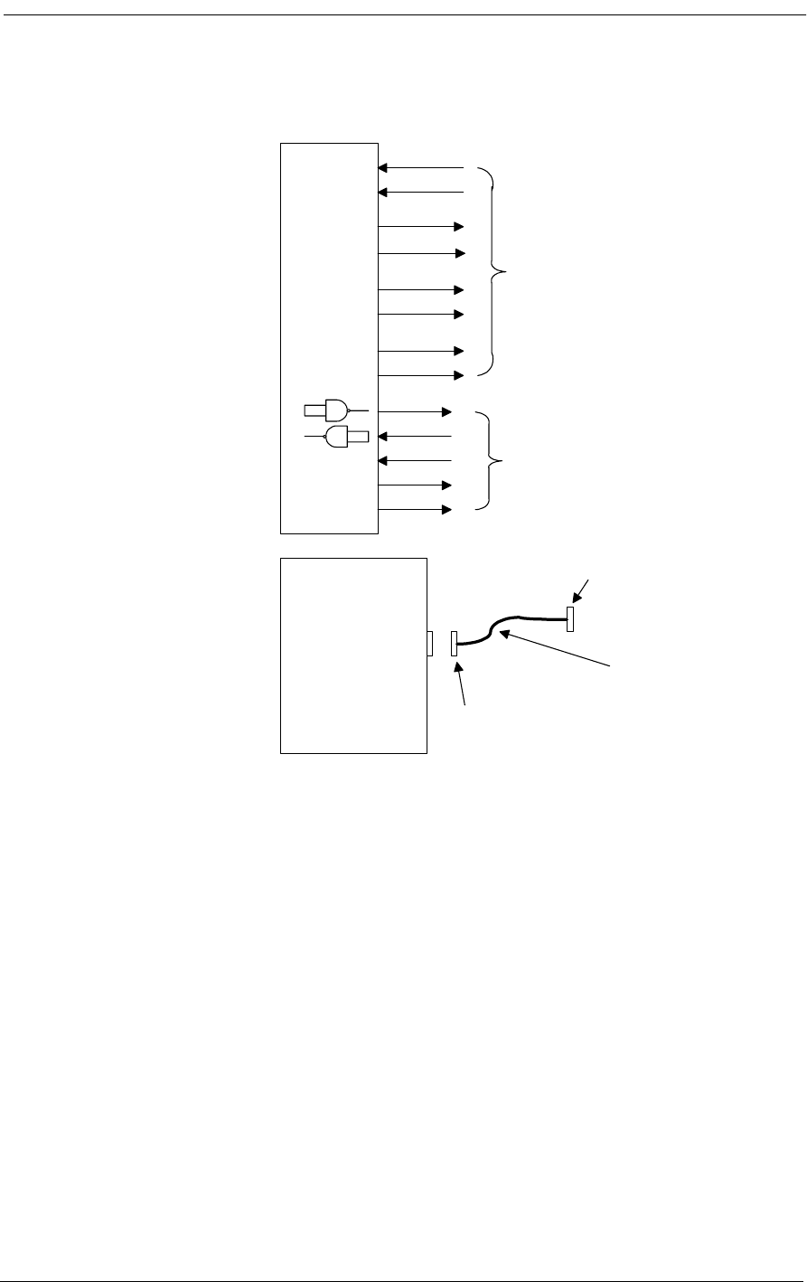
5-8 9/24/01
Figure 5-2: Access Bank II SNMP V.35 DCE Data Port Connections
TXA
TXB
RXA
RXB
RCLKA
RCLKB
TCLKA
TCLKB
CD
RTS
DTR
CTS
DSR
± 12 V single-ended
± .55 V balanced
Access Nodal
Switch
Fine Pitch D-Sub-26 Male
AMP213300-3
Cable
10, 25, or 50 ft.
Available supply
± 5V
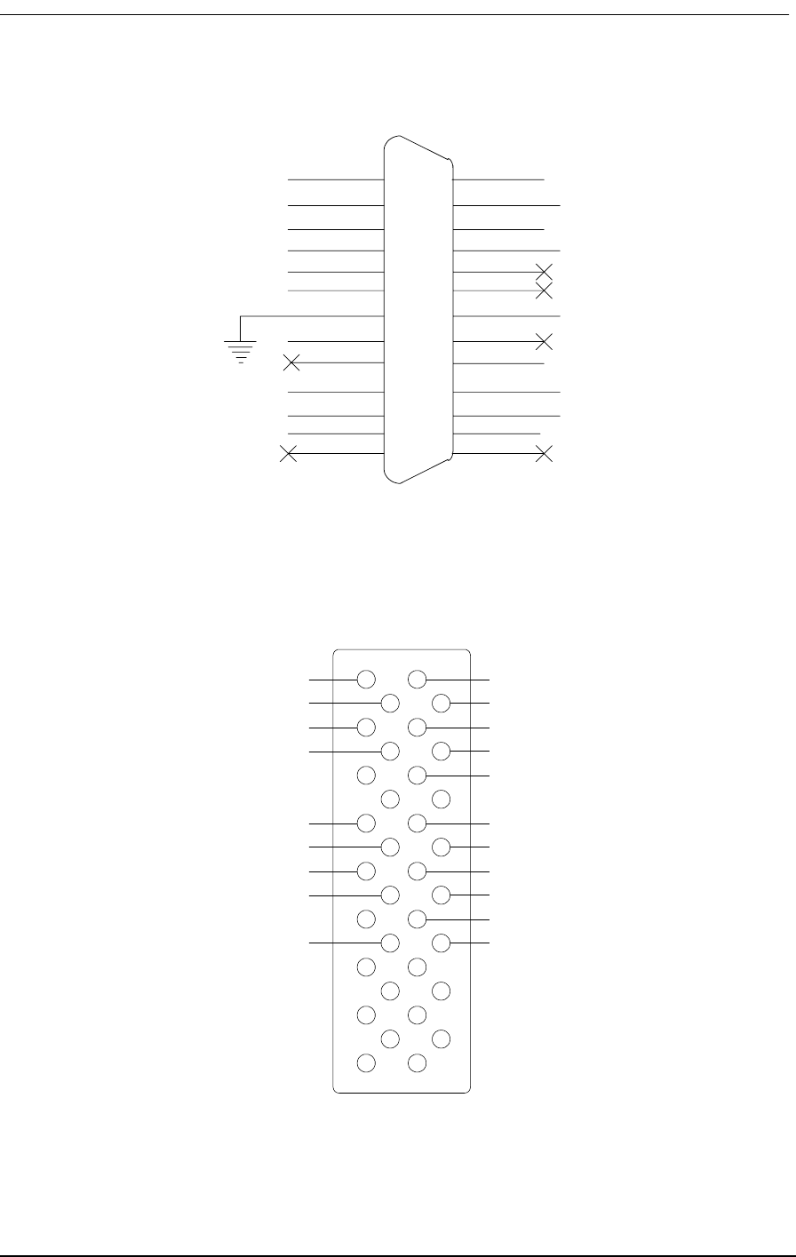
V.35 DCE Data Port Connections
9/24/01 5-9
Figure 5-3: Access Bank II SNMP V.35 DCE Port (female)
Figure 5-4: 34-pin V.35 Winchester Connector (male)
14 TXB (103)
15 RCLKA (115)
16 RXB (104)
17 RCLKB (115)
18
19
20 VDTR (108/2)
21
22 LLB (141)
23 TOLKB (114)
24 EXCLKB (113)
25 RDL (140)
26
CHASSIS 1
(103) TXA 2
(104) RXA 3
(105) VRTS 4
(106) VCTS 5
(107 VDSR 6
(109) VCD 8
(114) TCLKA 10
(113) EXCLKA 11
(142) TM 12
13
9
7
B
F
D
J
R
T
V
X
BB
A
E
C
H
K
P
S
U
W
Y
AA
Chassis Ground
Request to Send
Data set ready
Data terminal ready
Test mode
Transmitted data
Terminal timing
Transmit timing
Transmitted data
Terminal timing
Transmit timing
Signal ground
Clear to send
Receive line signal detect
Local loopback
Received data
Received data
Receive timing
Receive timing
Remote loopback
Signal
Description
Signal
Description
PINS
(interexchange circuits)

5-10 9/24/01
5.7 RS-232 Management
5.7.1 RS-232 DCE Management Cable
Note: The Dual RS-232 DCE Data and Management Cable (P/N 005-0001) is an
optional accessory, and can be purchased from distributors and dealers of CAC
products.
5.7.2 Local Management Cable
To perform local or remote management and performance monitoring using the Command Line Inter-
face or MS Windows-based Remote Monitor software installed in a local PC or laptop computer
requires using the CAC 25-Pin Local Management Cable (P/N 005-0003). This 10-foot cable is
equipped with a 26-pin male D-type subminiature connector on the end that mates with the Access
Bank II SNMP RS-232 secondary data port (COM2) and a DB25 female connector on the DCE end
for connection to the RS-232 communications interface of the local PC or laptop. Both this cable and
a 25-pin to 9-pin “straight adapter” (P/N 005-0007-25M-9F-Straight) are included with the Access
Bank II SNMP, permitting attachment to laptop computer DB9 ports.
Figure 5-5 shows these connectors and connection points.
Figure 5-5: CAC Local Management Cable
The CAC Local Management Cable is built according to the pin assignments listed in Table 5-6.
GND
TXD
RXD
RTS
CTS
DTR
CD
7 GND
14 STXD
16 SRXD
19 SRTS
13 SCTS
10 SDTR
12 SCD
7 GND
2 TX
3 RX
4 RTS
5CTS
20DTR
8CD
BRAID
1 SHIELD 1 SHIELD
RS-232 Management
Data Port (Com2) on
Nodal Switch
D-SUB-26 (male)
SECONDARY
DCE-DB-25
(female)
Local PC with Remote
Monitor Software
10 ft.

RS-232 Management
9/24/01 5-11
Table 5-6: CAC Local Management Adapter Cable Pin Assignments
5.7.3 Null Modem Adapter
Converting the Access Bank II SNMP from local management to dial-in/dial-out remote manage-
ment and/or alarm reporting requires using the 25-pin male to 25-pin male CAC Null Modem
Adapter (P/N 005-0002) included with each Access Bank II SNMP purchase. The Null Modem
Adapter is equipped with a DB25 RS-232 male connector on the DTE end and an RS-232 DB25 male
connector on the DCE end. The DTE DB25 male connector can be connected either to the 25-pin
DCE female connector on the CAC Local Management Cable described above, or to the 25-pin
female connector on the RS-232 data connector on the DCE end of the CAC Dual RS-232 DCE Data
and Management Cable. The 25-pin DCE female RS-232 end is for attachment to a Hayes-compati-
ble modem for dial-in/dial-out to a remote printer or pager, or to a remote 486 or higher PC with the
MS Windows-based Remote Monitor software or MS Windows Hypterterm (or compatible) VT100
emulation program installed. These programs are included with every Access Bank II SNMP.
Figure 5-6 shows the connection points.
Figure 5-6: CAC Null Modem Adapter
The CAC Null Modem Adapter is built according to the pin assignments defined in Table 5-7.
Designation DCE-DB25
(female) D-Sub-26
(male) Paired Signals
(Not required)
Shield 1+ (shield) 1+ (shield)
Ground 7 7
Secondary TXD 2 14
Secondary RXD 3 16 °
Secondary RTS 4 19
Secondary CTS 5 13 °
Secondary DTR 20 10
Secondary CD 8 12 °
GND
RXD
TXD
CTS
RTS
CD
DTR
7 GND
2 TX
3 RX
4 RTS
5 CTS
20 DTR
8 CD
7 GND
3 RX
2 TX
5 CTS
4 RTS
8 CD
20 DTR
BRAID
1 SHIELD 1 SHIELD
Carrier Access female
DB25 DCE Mgt. cable
005-0003 or female
DB25 DCE user data
cable 005-0001
DCE DB25 (male) DTE DB25 (male)
Remote Management
(modem)
DB25 M to DB25 M
Null Modem

5-12 9/24/01
Table 5-7: Null Modem Adapter Pin Assignments
5.7.4 Straight Adapter
The CAC Straight Adapter (P/N 005-0007-25M-9F-Straight) permits connecting the 9-pin COM1
communication port on a local Laptop computer to the 25-pin DCE data female connector on the
Dual RS-232 DCE Data and Management Cable, or to 25-pin female DCE connector on the Local
Management Cable. Figure 5-7 shows these connections points.
Figure 5-7: CAC Straight Adapter
The CAC Straight Adapter is built according to the pin assignments listed in Table 5-8.
Designation DCE DB25 (male) DTE DB25 (male) Paired Signals
(Not required)
Shield 1+ (Shield) 1+ (Shield)
Ground 7 7
Secondary TXD 3 2
Secondary RXD 2 3 °
Secondary RTS 5 4
Secondary CTS 4 5 °
Secondary DTR 8 20
Secondary CD 20 8 °
GND
TXD
RXD
RTS
CTS
DTR
CD
7 GND
2 STXD
3 SRXD
4 SRTS
5 SCTS
20 SDTR
8 SCD
5 GND
3 TX
2 RX
7 RTS
8 CTS
4 DTR
1 CD
BRAID
1 SHIELD 1 SHIELD
Carrier Access female
DB25 DCE Mgt. cable
005-0003 or female
DB25 DCE user data
cable 005-0001
DCE DB25 (male) DCE Female
DB-9
COM-1 Management
Local laptop
DB25 M to DB25 M
Null Modem
COM-1 Management
Connection

Connecting the Power and Ground
9/24/01 5-13
Table 5-8: CAC Straight Adapter Pin Assignments
5.8 Connecting the Power and Ground
5.8.1 DC Power Connector Input
Warning: Connect only -48 Vdc power to the DC input connector.
The Access Bank II SNMP has a 3-position DC Power Connector Input located on the Control Panel,
as shown in Figure 5-1. To conform with UL 1459 and National Electrical Code safety requirements,
the Access Bank II SNMP is equipped with solid-state, automatic-resetting, current-limiting devices
to protect the -48V Input and +DC Return power inputs on this connector from AC power surges,
lightning, or inductive motor spikes. This means there are no internal fuses for you to replace.
Pinout assignments for this connector are defined in Table 5-9.
Table 5-9: Power Connector Pinout Assignments
Designation DCE DB9 female DCE DB25 male Pair Signals
(Not required)
Shield + (Shield) 1+ (Shield)
Ground 5 7
Secondary TXD 3 2
Secondary RXD 2 3 °
Secondary RTS 7 4
66 °
Secondary DTR 4 20
85 °
Secondary CD 1 8 °
922
Pin Number Signal
1 AB115 Power Converter Cube, or -42 to -58 Vdc
power source
2 DC return, to power supply + terminal
3 Telco or safety (green-wire) ground
!

5-14 9/24/01

About This Chapter
9/24/01 6-1
Chapter 6
Initialization and
Basic Configuration
Contents of This Chapter:
6.1 About This Chapter
This chapter describes how to initialize and configure the Access Bank II - SNMP for first time basic
operation in Local mode.
6.2 Connecting to the Access Bank
Connect to the Access Bank II - SNMP Management cable using a terminal (or terminal emulation
program) set for 9.6 Kbps, 8, 1, None. The steps below guide you from factory defaults through the
standard TCG configuration. In this guide, the italicized items are what you type in. End each com-
mand line with the Enter key.
About This Chapter .................................... 1
Connecting to the Acces Bank ................... 1
Configuring the Access Bank ..................... 2
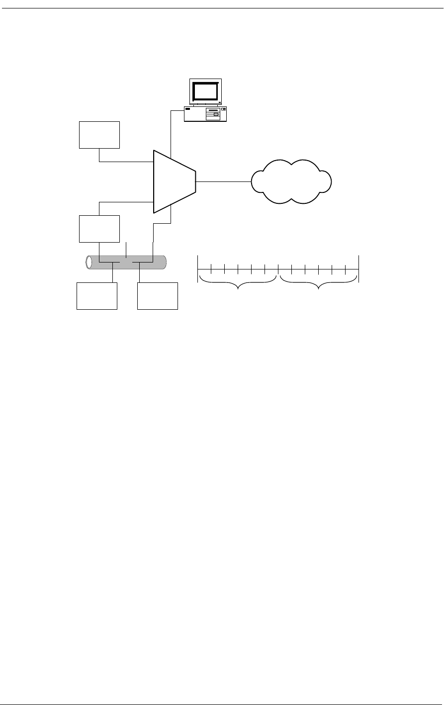
6-2 9/24/01
Figure 6-1: The AB-II SNMP in an Example Network
6.3 Configuring the Access Bank
1. Start the system and connect the terminal. The system displays:
Booting...
Configuring to restored configuration...
- Setting channel types
- Setting signal types
- Setting connections
- Setting ds1 configuration
- Setting I/O configuration
- Setting V.35 configuration
- Setting RS-232 Data Port
- Setting APS configuration
- Setting APS threshold
- Setting log enables
- Removing any data loopbacks
+++AT&FE1V1X4&D0&S0S=1
Enter <ESC> to login:
2. Press the <ESC> key. The display then reads:
ABII
SNMP
Key
System
Unit
Management
Station
Router
PCPC
LAN
V.35
FXS
RS-232
Service
Provider
T1
Þ
ESF/B8ZS
10baseT
SNMP
Access
12 FXS Voice
Channels
768 Data
to V.35
12
240
T1

Configuring the Access Bank
9/24/01 6-3
Access Bank II Version 1.01
Management Version 1.29
Password:
3. Enter the password (default is cac), and press <enter>.
Password: cac
Password accepted
Access Bank II
Access Bank II/SNMP
Slot Card Revision
--------- --------- ---------
LIU ABII 1.23
FX#1 FXS12 3.03
FX#2 --- ---
Span Name
--------- ----------------------------------
1) d1 ""
2) d2 "T1 #2"
3) f1 "FX #1"
4) f2 "FX #2"
4. Check the system clocking configuration:
Access Bank II> clk
- System Clock
clk primary t11
clk secondary internal
• If this is not the clocking configuration, enter:
Access Bank II> clk primary t11
5. Check the date information:
Access Bank II> date
- System Time 13:27:10 09/13/1998
• To correct the date (example is January 15, 1998):

6-4 9/24/01
Access Bank II> date 01/15/98
Access Bank II> date
- System Time 13:27:10 01/15/1998
6. Check the time information:
Access Bank II> time
- System Time is 13:27:08 01/15/1998
• To correct the time (example is 5:20 PM):
Access Bank II> time 17:20:00
Access Bank II> time
- System Time is 17:20:05 01/15/1998
7. To change and then recheck the system and circuit names (examples are provided here):
Access Bank II> name system "Consolidated National Bank"
Access Bank II> name circuitid d1 "T1 Circuit AD456-7Y"
Access Bank II> name circuitid d2 "T1 Port 2 - Not in Service"
Access Bank II> name circuitid f1 "FXS Channels to KSU"
Access Bank II> name circuitid f2 "Analog Slot 2 - Not in Service"
Access Bank II> name circuitid v1 "V.35 @ 768Kbps to Router"
Access Bank II> name
- Name Configuration
name system "Consolidated National Bank"
name circuitid d1 "T1 Circuit AD456-7Y"
name circuitid d2 "T1 Port #2 - Not in Service"
name circuitid f1 "FXS Channels to KSU"
name circuitid f2 "Analog Slot 2 - Not in Service"
name circuitid v1 "V.35 @ 768Kbps to Router"

Configuring the Access Bank
9/24/01 6-5
8. Check the configuration of T1 port #1:
Access Bank II> ds1 1
- DS1 d1
ds1 d1 circuitid "T1 Circuit AD456-7Y"
ds1 d1 csu on
ds1 d1 lbo dsx0|csu0
ds1 d1 linetype d4
ds1 d1 linecode b8zs
ds1 d1 prm att
• To change the framing and then check the configuration:
Access Bank II> ds1 1 linetype esf
Access Bank II> ds1 1
- DS1 d1
ds1 d1 circuitid "T1 Circuit AD456-7Y"
ds1 d1 csu on
ds1 d1 lbo dsx0|csu0
ds1 d1 linetype esf
ds1 d1 linecode b8zs
ds1 d1 prm att
• To remove all the connections between T1, Analog, and V.35 ports:
Access Bank II> kill d1
Access Bank II> kill d2
• To set the connections (example is channels 1-12 of T1 #1 to V.35 port, channels 13-24
of T1 #1 to FXS card in first analog slot):
Access Bank II> make v1 d1:1 12
Access Bank II> make d1:13 f1:1 12
Access Bank II> connections
1) Span d1: "T1 Circuit AD456-7Y"
v1:01 v1:02 v1:03 v1:04 v1:05 v1:06 v1:07 v1:08 v1:09 v1:10 v1:11 v1:12
f1:01 f1:02 f1:03 f1:04 f1:05 f1:06 f1:07 f1:08 f1:09 f1:10 f1:11 f1:12
2) Span d2: "T1 Port #2 - Not in Service"

6-6 9/24/01
_____ _____ _____ _____ _____ _____ _____ _____ _____ _____ _____ _____
_____ _____ _____ _____ _____ _____ _____ _____ _____ _____ _____ _____
3) Span f1[FXS12]: "FXS Channels to KSU"
d1:13 d1:14 d1:15 d1:16 d1:17 d1:18 d1:19 d1:20 d1:21 d1:22 d1:23 d1:24
4) Span f2[---]: "Analog Slot2-NotinService"
_____ _____ _____ _____ _____ _____ _____ _____ _____ _____ _____ _____
• To check the configuration of the V.35 port:
Access Bank II> v35
- V.35 v1 (768000 bps)
v35 v1 circuitid "V.35 @ 768Kbps to Router"
v35 v1 clkinv none
v35 v1 cts high
v35 v1 datainv none
v35 v1 rxclk internal
v35 v1 speed nx64
• To set the ip configuration, if required (examples given below):
Access Bank II> ip addr 125.164.0.35
Access Bank II> ip nms1 125.164.0.4
Access Bank II> ip
ip addr 125.164.0.35
ip mask 255.255.255.0
ip gateway 127.0.0.1
ip nms1 125.164.0.4
ip nms2
ip nms3
ip get "public"
ip set "public"
ip trap "public"
• To set SNMP configurations, if required (examples given below):
Access Bank II> snmp name "Voice and Data Access Multiplexor"
Access Bank II> snmp location "Metro Parkway, Wykham"

Configuring the Access Bank
9/24/01 6-7
Access Bank II> snmp contact "George Abbot, 203-345-8897, PIN #33345"
Access Bank II> snmp on
Access Bank II> snmp
- SNMP Group
- Access Bank II/SNMP
snmp name "Voice and Data Access Multiplexor"
snmp location "East Georgetown"
snmp contact "Nicholas Jones, 203-555-8897, PIN #33345"
9. IMPORTANT: Save the configuration, and exit the command line interface:
Caution: When you complete the following sequence, do not press the <esc>
key.
Access Bank II> config save
Access Bank II> exit
Logging out of Access Bank II
Enter <ESC>
10. You may now disconnect the local terminal, or end the remote login session.

6-8 9/24/01

About This Chapter
9/24/01 7-1
Chapter 7
Remote Monitor
Contents of This Chapter:
7.1 About This Chapter
This chapter describes how to initialize and configure the Access Bank II - SNMP for first time basic
operation in the Remote mode using the MS Windows-based Remote Monitor GUI software program
installed on an external IBM-compatible Laptop or PC.
Procedures are provided for:
• Installing the Remote Monitor software program
• Logging into the PC database
• Selecting a profile and default configuration
• Modifying Selecting Cross-Connect configurations
• Configuring the Dual T1 Hardware Interfaces
• Configuring the V.35 DCE Data Port
• Configuring the RS-232 Management Port
• Enabling Alarm Reporting to Pagers and Remote Printers
A more detailed explanation of the operation of the Remote Monitor is provided in the Remote Mon-
About This Chapter .................................... 1
Remote Monitor Software Program ........... 2
Overview .................................................... 2
Message Traffic ......................................... 3
Online Help ................................................ 3
Hardware Requirements ............................ 3
Installation .................................................. 3
Remote Monitor Screen Hierarchy ............ 4
Initialize for Operation in the Remote Mode 4
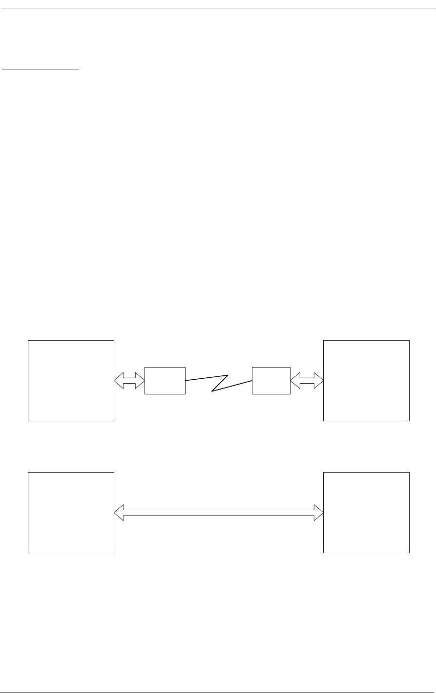
7-2 9/24/01
itor User’s Guide.
7.2 Remote Monitor Software Program
7.2.1 Overview
The Access Bank Remote Monitor software interface is used to configure and manage the Access
Bank via the RS-232 Management Port. Installed on a local IBM-compatible PC or laptop connected
to the RS-232 Management port, Remote Monitor provides a convenient user-friendly software inter-
face for configuring, monitoring, and testing the performance of the Access Bank. The Remote Mon-
itor software can also be downloaded into a remote computer for dial-in/dial-out management over a
separate PSTN (Public Switched Telephone Network) analog line. In this application, Remote Moni-
tor can also be used to poll the Access Bank for remote alarms via a Hayes-compatible modem
attached to the secondary connectors of the RS-232 Management port. Figure 7-1 illustrates these
two different ways of connecting Remote Monitor to the Access Bank.
Figure 7-1: Remote Monitor Connections
7.3 Message Traffic
The Remote Monitor software supports three classes of message traffic between the PC and the
Windows Based
Remote Monitor Access Bank II
Modem Modem
Windows Based
Remote Monitor Access Bank II

Online Help
9/24/01 7-3
Access Bank: configuration traffic between the PC and the Access Bank, status traffic from the
Access Bank to the PC, and alarm report messages from the Access Bank to the PC. The X-modem
protocol is used to send/receive data from the Access Bank. A low-priority process resides in the
Access Bank to process the X-modem packets and update the internal data structures accordingly.
Statistical data and error handling are processed by internal processes and sent to the remote monitor
via X-modem packets. The Remote Monitor software can also be used to perform V.54 loopback test-
ing to sectionalize and stress test the V.35 remote link using a full array of industry standard QRSS
test patterns.
7.4 Online Help
If you need specific information on performing any Remote Monitor operation, press the F1 key from
any screen to access a detailed system of context-sensitive online Help. When you place the cursor
over certain control fields, Remote Monitor also responds with handy tips for performing that partic-
ular task. For step-by-step instructions on all aspects of installing, configuring and operating the
Remote Monitor GUI software interface, refer to the separate Remote Monitor User’s Guide. If you
need information on using Microsoft Windows, refer to your Windows documentation.
7.5 Hardware Requirements
The PC you use as a Network Management Station (NMS) should meet these minimum require-
ments:
• 486 66 MHz or Greater (Pentium 100 MHz -preferred) CPU
• 16 MBytes RAM memory
• 10 Mbytes available hard disk space
• VGA monitor with 640 x 480 resolution and 8-bit (256 colors) color
• Windows 3.1/Windows 95
• Keyboard
• Mouse
7.6 Installation
The Remote Monitor software is distributed on four 3 ½ “ diskettes and is designed to operate under
both Windows 3.1 or Windows 95 environments. Use the following procedure to load Remote Moni-
tor onto the PC platform you wish to use as a Network Management Station (NMS) to monitor and
configure the Access Bank:
1. Place Disk 1 into the 3 ½ “ disk drive and select Run from the Start button of Windows 95 or
Windows 3.1.
2. Open the Setup.exe file.

7-4 9/24/01
3. The install wizard should execute and be displayed on the screen.
4. Select the location defaults and insert the appropriate diskettes when prompted.
7.7 Remote Monitor Screen Hierarchy
The Remote Monitor software interface consists of a hierarchy of screens or windows. The following
figure presents a simplified functional block diagram of this screen hierarchy.
Figure 7-2: Access Bank Remote Monitor Screen Hierarchy
7.8 Initialization for Basic Operation in the Remote Mode
For information about initialization and basic operation of the Access Bank in the Remote Mode and
for first time use, see the Access Bank User’s Guide.
Remote
Monitor
PC Setup PC Data Base
Setup
Configuration
PC Setup
System Definition T1 Protection Static Connection Channel/Signaling
Type
Hardware Setup Craft Port RS-232 Data Port V.35 Data PortT1 Setup Real-time
Clock
Performance T1 History Codec
Performance
Maintenance

9/24/01 8-1
Chapter 8
FXS-ID Configuration
Contents of This Chapter:
8.1 About This Chapter
This chapter describes how to configure the Access Bank II - SNMP Foreign Exchange Station -
Caller ID (FXS - ID) 12-channel voice card for connection to T1 public network services and pro-
vides instructions for:
• Setting FXS Transmit and Receive Levels
• Setting FXS Signaling Type Options
• Performing FXS Voice Channel Monitoring and Testing
8.2 FXS-ID Voice Card
The Foreign Exchange Station - Caller ID (FXS-ID) 12-channel voice card delivers high quality
loop-start or ground-start dial tone telephone line connections to key systems, Off Premise Exten-
sions (OPXs), facsimile machines, modems, PBXs and other conventional analog telephone devices.
The FXS - ID card supports the Caller ID CLASSÆ feature. The FXS -ID, is a 7.8” by 13.16” daugh-
ter card designed to slide into the back of the Access Bank II - SNMP along rails that guide a 64-pin
DIN connector to mate with a matched connector on the internal AB2 Controller. The FXS-ID card
receives the T1 signaling, tip and ring pairs, control logic and power through this connector. The back
About This Chapter .................................... 1 FXS Signaling Option Descriptions .......... 8
FXS-ID Voice Card .................................... 1 Option Switches A, B, and C..................... 8
Signaling Types ......................................... 2 TP Busy/Idle Switch ............................... 11
FXO Switch to AB2 FXS A/B Signaling ..... 2 Voice Channel Monitoring and Testing .. 11
Wink-Start to Loop-Start or Ground-Start .. 2 FXS Backplate Switches ........................ 12
Wink Delay ................................................. 3 FXS Backplate LEDs .............................. 12
Setting the Transmit and Receive Levels .. 3 “Busying Out” Individual FXS Channels . 12
Setting the Signaling Options .................... 6 Self Test Loopbacks ............................... 13
Option Switches A, B, and C ..................... 6

FXS-ID Configuration
8-2 9/24/01
plate of the FXS-ID card has 12 channel status LEDs and one 4-position DIP switch for selecting
from a number of different signaling types. Furthermore, the back plate also contains 12 test switches
that can be used to “busy out” each channel individually. On the FXS-ID card itself, each individual
channel has a 6-position DIP switch for setting transmit and receive line attenuation.
When equipped with the Foreign Exchange Station - Caller ID (FXS-ID) voice card, the Access
Bank II - SNMP can support a number of popular signaling types used by dedicated T1-accessed
voice service providers, including:
• AT&T Megacom (E&M Wink-Start)
• NYNEX Flexpath“ (E&M Wink-Start)
•US West DSS
“
• Long-distance Automatic Number Identification (ANI) and Dialed Number Identifica-
tion Service (DNIS) from MCI, Sprint, LDDS, and Wiltel.
The FXS circuits automatically perform impedance matching (not to be confused with DS-1 ALBO)
to adapt to various PBXs, key systems, telephones and line lengths.
8.3 Signaling Types
The FXS-ID voice card can be configured, using DIP switches on the card, to support the following
common signaling types:
• FXO in the Central Office (CO)-to-AB2 FXS A/B Signaling (regular 3-state FXS signal-
ing)
• E&M Immediate Start to Loop-Start/Ground-Start
• Wink-Start to Loop-Start/Ground-Start
• Wink Delay (ANI/DNIS) for Loop-Start/Ground-Start
8.3.1 FXO Switch to AB2 FXS A/B Signaling
Select the default setting to have Access Bank II - SNMP FXS interfaces automatically adapt to loop-
start or ground-start signals received from the incoming T1 line on a channel-by-channel basis. This
option is used when an FXO voice card is in the Central Office, at the other end of the T1 link oppo-
site the FXS-ID card. It is important to note that in this configuration, the Caller ID CLASS feature
can only be supported if the FXD voice card in the CO also supports this feature.
8.3.2 Wink-Start to Loop-Start or Ground-Start
Select Wink-Start to Loop-Start or Ground-Start to translate two-state wink-start signaling from the
T1 network (AT&T Megacom, Flexpath, etc.) to loop-start or ground-start ringing at the FXS inter-
face. Ringback tone is supplied on the T1 transmit path during the ringing state of the FXS. This con-
figuration options all 12 FXS channels to appear as E&M wink-start channels to the serving carrier
switch, while providing the customer with standard dial tone/ringing telephone line connections.
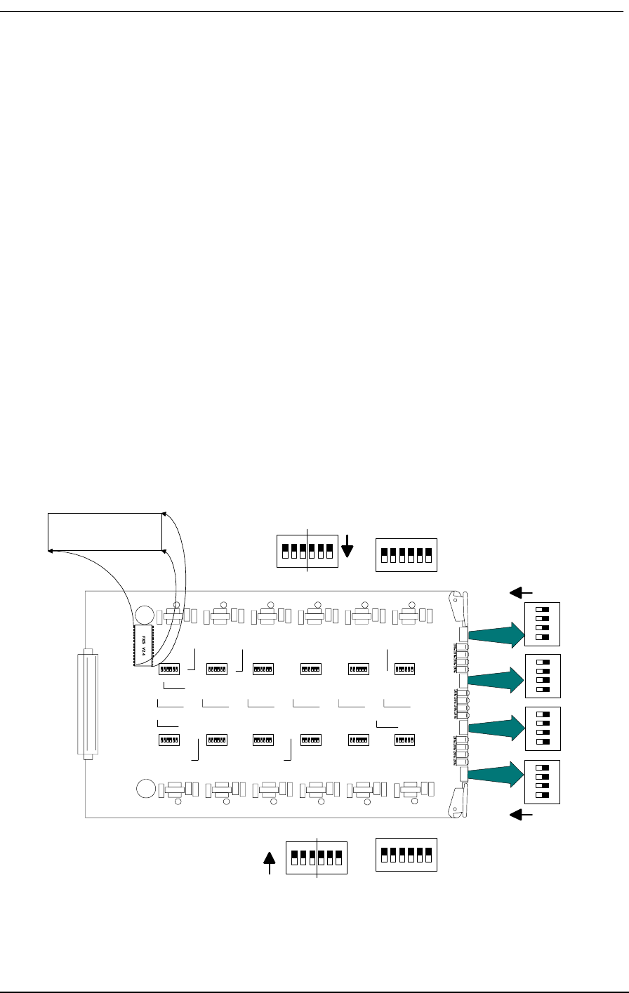
Setting the FXS Transmit and Receive Levels
9/24/01 8-3
8.3.3 Wink Delay
Select Wink Delay to translate two-state wink-start signaling toward the T1 network to an FXS ring-
ing with delayed wink for proceed-to-send digit indication. Upon detection of an incoming seizure
from the T1 network, the AB2 applies ringing voltage to the FXS channel. When the attached equip-
ment answers by closing the loop, the Access Bank II - SNMP winks the network for “proceed to
send,” allowing the attached equipment to receive DTMF digits carrying Automatic Number Identifi-
cation (ANI) or Directory Number Identification Service (DNIS). This is particularly useful for voice
mail, voice response, call distribution, and automatic attendant applications. Standard loop-start PC
voice mail and fax cards can be used for ANI and DNIS applications, without the added expense and
complexity of installing signaling converters.
8.4 Setting the FXS Transmit and Receive Levels
The transmit and receive attenuation levels for each FXS voice frequency channel can be set between
0 and -9 dB using twelve 6-position DIP switches (CH1 - CH12) on top of the circuit board (see Fig-
ure 8-1). Each analog channel uses a bank of six DIP switches, with three for transmit and three for
receive. Operation of each set of three switches in additive. For example, setting switch 1 (-2 dB) and
switch 2 (-3 dB) to OFF for any given channel selects a receive loss of -5 dB. The default setting for
the transmit level is -3 dB; for the receive level it is -6 dB. The default settings are appropriate for
most applications.
Figure 8-1: FXS Transmit and Receive Level Options
UP (ON)
UP (ON)
4
3
2
1
4
3
2
1
4
3
2
1
4
3
2
1
XMTRCV
ON
1 2 3 4 5 6
XMT RCV
6 5 4 3 2 1
ON
BRFXS V x.x

FXS-ID Configuration
8-4 9/24/01
If your FXS voice channels require different attenuation level settings than the factory defaults, pro-
ceed as follows:
1. Release the two thumbscrews on the AB2 back plate and remove the plate (see Figure 8-2).
2. To remove the FXS-ID slide-in voice card, pull out the two card ejector latches simulta-
neously to release the card from the internal connector, then slide the card carefully out from
the rear of the AB2 chassis (see Figure 8-2).
3. To set different transmit and/or receive gain or loss levels, refer to Figure 8-1 and Table 8-1.
4. To reinsert the FXS-ID voice card, ensure that the card is positioned correctly in the card
rails, then carefully slide the card into the slot until it stops.
5. Press both card ejector latches in towards the FXS-ID card to seat the 64-pin DIN connector
in the matching connector on the internal Controller card.
6. After setting the transmit and receive level options, replace the back plate and tighten the
thumbscrews.
Table 8-1: FXS Transmit and Receive Level Option Settings
Switch Function (Switch OFF)
1 -2 dB Receive Loss
2 -3 dB Receive Loss
3 -4 dB Receive Loss
4 -2 dB Transmit Loss
5 -3 dB Transmit Loss
6 -4 dB Transmit Loss

Setting the FXS Transmit and Receive Levels
9/24/01 8-5
Figure 8-2: Accessing the FXS-ID Cards
Table 8-2: FXS Signaling Summary
Option
Number Switch
ASwitch
BSwitch
CSignaling
Option
0 OFF OFF OFF Normal FXS A&B signaling for loop-
start or ground-start; automatic selection
based on carrier signal. FXS-ID card
default.
1 ON OFF OFF E&M wink-start-to-loop-start conversion
with ringback to T1 line and calling party
disconnect (Megacom, Notes 1 and 2).
2 OFF ON OFF E&M wink-start-to-ground-start
conversion with ringback to T1 line
(Megacom, Note 1).
3 ON ON OFF E&M immediate-start-to-loop-start
conversion with ringback to T1 line and
calling party disconnect (Megacom,
Notes 1 and 2). Also known as Private
Line Automatic Ringdown (D3 PLAR).

FXS-ID Configuration
8-6 9/24/01
8.5 Setting the FXS Signaling Options
Each FXS-ID card contains one 4-position DIP switch that can be used to select signaling options for
all twelve channels. As shown in Table 8-2, the AB2 back plate provides openings for accessing these
DIP switches, one per FXS-ID card.
8.5.1 Option Switches A, B, and C
The three switches labeled Option A, Option B, and Option C are used as a group to select signaling
conversion options for all 12 channels of each FXS-ID card. When all three switches are set OFF
(default), the FXS voice circuits will automatically select ground-start or loop-start signaling on a
channel-by-channel basis according to the incoming T1 signal. See Table 8-2 for all switch combina-
tions.
TP Idle/Busy Switch
The fourth switch on each DIP switch, labeled TP Busy/Idle, selects whether the tip-ground relays are
busy (closed) or idle (open) during trunk processing. The default is idle (switch 4 OFF).
To change signaling options, refer to Table 8-2 and Figure 8-3. The numbered signaling options listed
in Table 8-2 are described in further detail in the next section.
4 OFF OFF ON E&M immediate-start-to-ground-start
conversion with ringback to T1 line
(Megacom, Note 1).
5 ON OFF ON Wink-start-to-loop-start conversion with
ANI/DNIS with 800 ms wink delay and
calling party disconnect (Notes 1, 2 and
3).
6 OFF ON ON Wink-start-to-ground-start conversion
with ANI/DNIS with 800 ms wink delay
(Notes 1 and 3).
7 ON ON ON Custom Signaling Options. Please
contact Carrier Access Corporation for
specific details (Note 4).
Note 1: Loop release implemented to prevent follow-up calls until the network A/B clears (no
timer).
Note 2: Calling party disconnect implemented as a 2-second tip-open state when the network A/B
clears.
Note 3: Wink-out provided after loop answer instead of after network seizure. This is the key dif-
ference between options 1 & 2 and options 5 & 6.
Note 4: If you select this DIP switch setting with no custom signaling option installed, the 12
channel LEDs on the FXS back plate turn a steady RED and normal service is interrupted.

FXS Signaling Option Descriptions
9/24/01 8-7
Figure 8-3: FXS Signaling Options
8.6 FXS Signaling Option Descriptions
8.6.1 Option Switches A, B, and C
Signaling options selected by the A, B, and C option switches are discussed below according to the
numbered sequence from 0 to 7 in Table 8-2.
8.6.1.1 Option 0. Normal FXS A&B Signaling, Loop-Start or Ground-Start
With this selection, the Access Bank II - SNMP FXS interfaces automatically adapt to loop-start or
ground-start signaling received from the T1 line on a channel-by-channel basis. When using this
option, order FXS loop-start or FXS ground-start signaling from your service provider.
8.6.1.2 Option 1. E&M Wink-Start-to-Loop-Start Conversion with Calling Party
Disconnect
The FXS-ID voice card provides Plain Old Telephone (POTS) loop-start interfaces to a PBX or regu-
lar telephones. E&M wink-start signaling and per-channel ringback tones are sent to the T1 line.
Calling Party Disconnect
Calling Party Disconnect (CDD) is a 2-second, tip-open condition at the FXS-ID when the network
releases seizure (the far-end called party hangs up). The battery feed from the FXS-ID returns to idle
(tip grounded) after the two-second disconnect. This feature is similar to local telephone service Call-
ing Party Disconnect (CPD), which some Central Office equipment provides for answering machines
and PBXs equipped to detect loss of loop current on their line interfaces. This loss of loop current
Switch A Switch B Switch C
OFF OFF OFF
Switch A Switch B Switch C
ON OFF OFF
Signaling Options
& Busy/Idle
Signaling Options
& Busy/Idle

FXS-ID Configuration
8-8 9/24/01
informs the equipment to hang up.
8.6.1.3 Option 2. Wink-Start to Ground-Start Conversion
POTS Interface
This option provides a POTS (Plain Old Telephone Service) ground-start interface between the
Access Bank II - SNMP and the PBX or other phone equipment. This avoids both-way call collisions
(“glare”) on PBX trunks and gives the PBX a disconnect signal when the far-end party hangs up.
E&M wink-start signaling and ringback tones are sent to the T1 line on an individual channel basis.
This option is for use with AT&T Megacom, NYNEX Flexpath or equivalent E&M services from
other service providers.
8.6.1.4 Option 3. E&M Immediate-Start-to-Loop-Start Conversion
Private Line Automatic Ringdown (D3 PLAR)
Known as D3 Private Line Automatic Ringdown (D3 PLAR), this option provides a “hot-line” ring
down function from the near-end telephone to the far-end telephone connected over the same channel
of the T1 line. The first telephone to go off-hook seizes the channel with a signaling bit sequence of
A/B = 11 and hears a cadenced ringback tone (2 seconds on, 4 seconds off) from the far-end channel
bank. The far-end disconnects the ringback tone and sends A/B = 11 to the originating end when its
telephone goes off-hook. D4 PLAR is not supported.
To use this option, order E&M immediate-start service from your service provider.
8.6.1.5 Option 4. E&M Immediate-Start-to-Ground-Start Conversion
This is the same as the E&M immediate-start-to-ground-start conversion option for services such as
AT&T Megacom and NYNEX Flexpath.
To use this option, order E&M immediate-start service from your service provider.
Switch A Switch B Switch C
OFF ON OFF
Switch A Switch B Switch C
ON ON OFF
Switch A Switch B Switch C
OFF OFF ON

FXS Signaling Option Descriptions
9/24/01 8-9
8.6.1.6 Option 5. Wink-Start to Loop-Start Conversion with ANI/DNIS and
Calling Party Disconnect
This option provides a loop-start interface between the AB2 and the PBX for voice mail/phone
applications. E&M wink-start signaling and per-channel ringback tones are sent to the T1 line.
Ringing voltage is applied immediately after incoming seizure. The 200 ms outgoing wink “pro-
ceed-to-send” signal is not sent to the T1 network until 800 ms after FXS ringing voltage has been
tripped (answered). Thus, the voice mail or PBX DTMF or MF register has at least one second to
be attached to the line after closing the loop. The network proceeds to automatically send four to
ten ANI or DNIS digits.
User also receives a two-second Tip Open condition (loop current turns off) at the FXS-ID when
the network releases seizure (the far-end call hangs up). Battery feed from the FXS-ID returns to
normal idle (tip grounded) after the two-second disconnect. This feature is similar to local tele-
phone service Calling Party Disconnect (CPD), provided by some Central Office equipment for
answering machines and PBXs that are equipped to detect loss of loop current on their line inter-
faces. This loss of loop current informs the equipment to disconnect the call.
8.6.1.7 Option 6. Wink-Start to Ground-Start Conversion with ANI/DNIS
This option provides a ground-start interface between the AB2 and the PBX for voice mail/phone
applications. E&M wink-start signaling and per-channel ringback tones are provided to the T1
line.
Ringing voltage is applied immediately after incoming seizure. The 200-ms outgoing wink “pro-
ceed-to-send” signal is not sent to the T1 network until 800 ms after FXS ringing voltage has been
tripped (answered). Thus, the voice mail or PBX DTMF or MF register has at least one second to
be attached to the line after closing the loop. The network proceeds to automatically send 4 to 10
ANI or DNIS digits.
8.6.1.8 Option 7. Customized Signaling
Switch A Switch B Switch C
ON OFF ON
Switch A Switch B Switch C
OFF ON ON
Switch A Switch B Switch C
ON ON ON

FXS-ID Configuration
8-10 9/24/01
Caution: If you use this setting when no customized signaling has been
installed, all back plate LEDs turn a steady RED and normal operation of the
FXS-ID voice card is interrupted.
Upon request, Carrier Access will provide customized FX signaling options that can include any
of the aforementioned options plus others, including answer supervision wink signaling.
Answer Supervision Wink Signaling
Answer supervision wink signaling takes the form of a 200-ms tip-open condition (loop current
turns off) from the Access Bank II - SNMP to the voice-mail or phone system when the far end
goes off hook (answers the call). Battery feed from the FXS-ID returns to normal (tip grounded)
after the 200-ms disconnect. This feature is useful if the calling party switch needs to know when
the far end has answered the call.
8.6.2 TP Busy/Idle Switch
Use this switch to select whether the FXS tip-ground relays will be closed (busy) or open (idle) dur-
ing trunk processing. (Trunk processing occurs when the T1 line is in an alarm or reset state.) The
Busy position (OFF) causes the tip-ground relays to be closed during a T1 alarm or reset period. The
Idle position ON) causes the tip-ground relays to be open during a T1 alarm or reset period.
Note: The Busy position (OFF) is recommended for loop-start or ground-start
applications where the attached PBX has the ability to re-route calls to different
trunks when the T1 line is down.
8.7 FXS Voice Channel Monitoring and Testing
The channel status LEDs on the back plate of the Access Bank II - SNMP allow you to monitor the
status of the individual FXS voice lines. Operation of these LEDs is summarized in Figure 8-4.
ON OFF
Idle Busy
!

FXS Voice Channel Monitoring and Testing
9/24/01 8-11
The channel test switches on the FXS-ID back plate can be used to send a 4 second continuous ring-
ing voltage to the tip and ring pair of each FXS voice channel. You can check the operation of an
individual voice channel by attaching a test telephone to the Tip and Ring pair of a particular channel
at the punchdown block or RJ-11 Harmonica, then switching ON the appropriate channel test switch
to test that channel.
Figure 8-4: FXS-ID Back Plate Controls and LED Indicators
8.7.1 FXS Backplate Switches
Channel Test (12 per FXS card) - Sends four seconds of ringing to voice channel and four seconds of
ringback to the T1 channel. After ringing, it will busy out the T1 channel and the voice channel.
TP Busy/Idle (1 per FXS card) - selects busy or idle on tip-ground relays during trunk processing.
8.7.2 FXS Backplate LEDs
Table 8-3
LED
State Condition
OFF Idle state (FXS ground start, all E&M
settings
GREEN Idle stae (normal FXS loop-start
operation): Incoming seixure (ground
start operaion or E&M conversion)
YELLOW Call in progress
RED Outgoing line seizure
All LEDs
YELLOW
S
AB2 in trunk processing
All LEDs
flash RED
Unsupported signaling option selected

FXS-ID Configuration
8-12 9/24/01
8.7.3 “Busying Out” Individual FXS Channels
Switching a channel test switch to the ON position has three results on the selected FXS channel:
1. To confirm individual channel circuit integrity, 4 seconds of ringing voltage are sent to the
Tip and Ring pair. The Tip is then grounded until the channel test switch is turned to the OFF
position (to the right).
Warning: Four seconds of ringing voltage (85 V) will be present at the Tip
and Ring pair of the FXS channel-under-test until the test telephone is picked
up to trip the ringing.
Requirement: A test telephone connected to the punch down block or RJ-11 Harmonica
should ring for 4 seconds.
2. As an aid to network technicians troubleshooting audio problems, 4 seconds of ringback tone
are also sent toward the T1 network.
3. After the 4 seconds of ringback tone, the FXS channel will “busy out” toward the T1 network
side.
Note: Each channel test switch can provide ringing during Trunk Processing (or
even when the T1 line is disconnected).
8.7.4 Self Test Loopbacks
During Self-Test, switching a channel test switch to the ON position has the following result:
The affected FXS channel receives 4 seconds of ringing voltage (85 V) and the LED for that particu-
lar channel turns RED. This allows a technician to ring the telephone and verify audio tone when it is
answered.
Note: During Self Test, a RED channel LED may come on, but does not indicate a
problem.
!
!

FXS Voice Channel Monitoring and Testing
9/24/01 8-13
Warning: The four-second applied ring voltage (85V) can constitute a
dangerous shock hazard, and can damage attached low-impedance equipment.

FXS-ID Configuration
8-14 9/24/01

9/24/01 9-15
Chapter 9
Battery Reversal FXS & Dial
Pulse Origination Card
Contents of This Chapter:
9.1 About This Chapter
This chapter describes how to configure the Access Bank II Battery Reversal Foreign Exchange Sta-
tion and Dial Pulse Origination (BRFXS/DPO) 12-channel voice card for connection to T1 public
network services and provides instructions for:
• Setting Transmit and Receive Levels
• Setting the FXS with battery reversal and DPO
• Performing Voice Channel Monitoring and Testing
9.2 Description of the BRFXS/DPO Card
The BRFXS/DPO 12-channel voice card can be configured to operate either as a battery reversal
FXS card or as a Dial Pulse Origination (DPO) card. In the battery reversal mode, the BRFXS/DPO
About This Chapter .................................... 1 Self Test Loopbacks................................. 9
Description of the BRFXS/DPO Card ........ 2
Overview of Operation ............................... 2
BRFXS/DPO Applications .......................... 3
Setting the Transmit and Receive Levels .. 4
Battery Reversal FXS Loop-Start .............. 8
Dial Pulse Origination (DPO)..................... 8
BRFXS/DPO Voice Ch Monitoring & Testing 8
Busying Out BRFXS/DPO Channels ......... 8

Battery Reversal FXS & Dial Pulse Origination Card
9-16 9/24/01
provides twelve 2-wire CPE analog loop-start connections to the digital T1 line using the same
method used by the FXS voice card, only with the addition of Tip/Ring battery reversal. The FXS
interface reverses the polarity of the battery feed towards the customer premise equipment (CPE) in
response to the signaling bits coming from the T1 line. Various PBX systems require battery reversal
to signal the start of billing, and in certain telephony environments it is needed to provide Line Side
Answer Supervision (LSAS). One important application for battery reversal occurs in International
Call Back, which allows international callers dialing the US to avoid more expensive inbound rates
by taking advantage of cheaper US outbound long distance rates.
Dial Pulse Origination (DPO) is the functional complement to Dial Pulse Termination (DPT) pro-
vided by the FXO/DPT voice card. Used in conjunction, the DPO and DPT cards are used mainly for
origination and termination of Direct Inward Dial (DID) circuits.
The BRFXS/DPO is a 7.8” by 13.16” daughter card designed to slide into the back of the Access
Bank II along rails that guide a 64-pin DIN connector to mate with a matched connector on the inter-
nal ABI Controller. The card receives the T1 signaling, tip and ring pairs, control logic and power
from the Controller card through this connector. The back plate of the card has 12 channel status
LEDs and one 4-position DIP switch for selecting between battery reversal FXS loop-start and Dial
Pulse Originating (DPO) modes of operation. Furthermore, the back plate also contains 12 test
switches that can be used to “busy out” each channel individually. On the BRFXS/DPO card itself,
each individual channel has a 6-position DIP switch for setting transmit and receive line attenuation.
9.3 Overview of Operation
The reversible-battery FXS channel card is designed to provide twelve 2-wire analog interfaces to the
digital T1 (DS1) line. Currently, the analog loops (also called CPE loops in this document) must
always be loop-start.
One of the main features of the analog interface is that the polarity of the battery feed towards the
customer-premise equipment (CPE) can be reversed in response to the signaling bits coming from the
T1 line.
• The basic operation is selected by setting Switch A off so that no ringing voltage is
applied towards the CPE. If desired, Switch B can be turned on to give a cadenced (2-
second/4-second) ringback tone to the T1 line during incoming calls. The battery to the
CPE loop will be reversed to indicate an incoming call. The battery will return to forward
polarity again when the call has ended.
• Also included in this channel card is a setting to provide cadenced ringing voltage (if
needed by other customer-premise equipment). This option is enabled by setting Switch
A on so that cadenced ringing voltage will be applied to the CPE loop during an incom-
ing call. The battery is reversed during this time. If desired, Switch B can be turned on to
give a cadenced (2-second/4-second) ringback tone to the T1 line during incoming calls,
that is synchronized to the ringing voltage present on the loop.
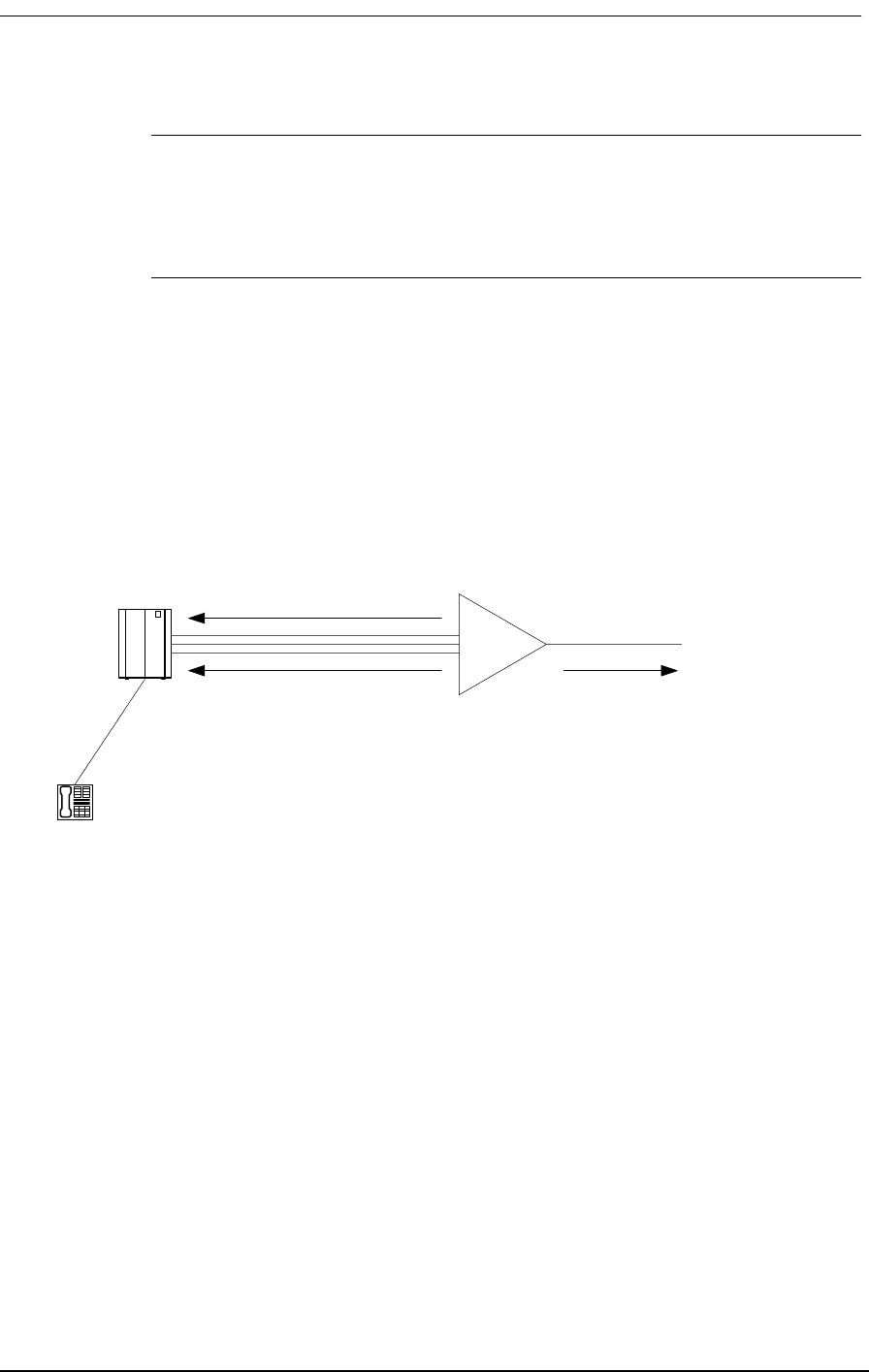
BRFXS/DPO Applications
9/24/01 9-17
Note: During a two-way call, the CPE -loop battery is reversed. To disconnect the
call either the CPE loop current ceases or the network sends A/B bits = 0/0. The
reversed state of the CPE loop, however, will be maintained until the network
terminates (releases) the call.
9.4 BRFXS/DPO Applications
As explained above, the two major applications for the BRFXS/DPO card are FXS with battery
reversal “wink” to signal a PBX timer to start billing a call and Dial Pulse Origination (DPO) for
transport of Direct Inward Dialing (DID) lines. Refer to Figure 9-1 and Figure 9-2 for pictorial repre-
sentations of these two applications.
Figure 9-1: Battery Reversal FXS Loop-Start for Starting PBX Billing Timer
DPO*
PBX Battery Reversal to PBX
T1
Optional cadenced
ringback tone to T1 during
incoming calls
Optional cadenced ringing
voltage applied to CPE
during incoming call
FXS loop-start lines
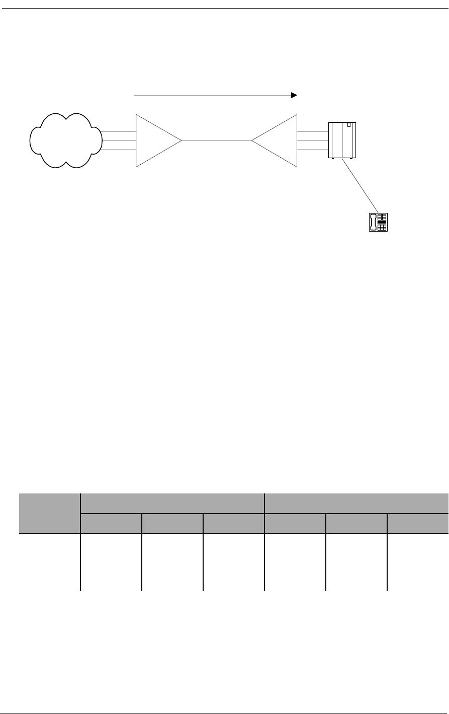
Battery Reversal FXS & Dial Pulse Origination Card
9-18 9/24/01
Figure 9-2: Dial Pulse Origination (DPO) for DID Transport
9.5 Setting the Transmit and Receive Levels
The transmit and receive levels for each BRFXS/DPO voice frequency channel can be set between 0
and -9 dB using twelve 6-position DIP switches (CH1 - CH12) on top of the circuit board card (see
Figure 9-3). Each analog channel uses a bank of six DIP switches, with three for transmit and three
for receive. Operation of each set of three switches in additive. For example, setting switch 1 (-2 dB)
and switch 2 (-3 dB) to OFF for any given channel selects a receive loss of -5 dB. The default setting
for the transmit level is -3 dB; for the receive level it is -6 dB. The default settings are appropriate for
most applications.
Table 9-1: Transmit and Receive Attenuation Switch Values
Switch
Setting
Transmit Switch Position Loss Receive Switch Position Loss
1 2 3 4 5 6
On000000
Off-2-3-4-2-3-4
Called Party's
Direct Extension
DPO*
DPT*
PBX
DID
Lines
Direct Inward Dial (DID)
Leased T1
* Use CAC's FXO/DPT 12-Channel
voice card
Remote LEC
Switch
DID
Lines
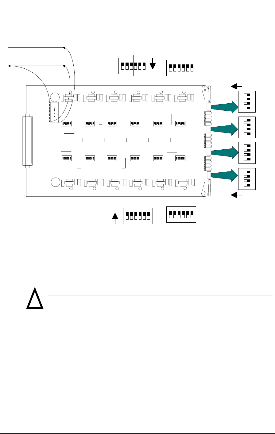
Setting the Transmit and Receive Levels
9/24/01 9-19
Figure 9-3: BRFXS/DPO Transmit and Receive Level Options
If your voice channels require different attenuation level settings than the factory defaults, proceed as
follows:
Caution: Use proper electrostatic discharge (ESD) procedures when
removing and handling the analog cards.
1. Release the two thumbscrews on the ABI back plate and remove the plate.
2. Pull out the two card ejector latches simultaneously to release the card from the internal con-
nector, then slide the card carefully out from the rear of the ABI chassis.
3. Set different transmit and receive gain or loss levels (see Figure 9-3 and Table 9-1).
4. Re-insert the BRFXS/DPO voice card, ensuring that the card is positioned correctly in the
card rails.
UP (ON)
UP (ON)
4
3
2
1
4
3
2
1
4
3
2
1
4
3
2
1
XMTRCV
ON
1 2 3 4 5 6
XMT RCV
6 5 4 3 2 1
ON
BRFXS V x.x
!

Battery Reversal FXS & Dial Pulse Origination Card
9-20 9/24/01
5. Press both card ejector latches in towards the FXS card to seat the 64-pin DIN connector in
the matching connector on the internal Controller card.
6. Replace the back plate and tighten the thumbscrews.
9.6 BRFXS/DPO Configuration Settings
The configuration of the Battery Reversal FXS/DPO card is set by a 4-position DIP switch and 12
individual channel test switches accessed through the ABI back plate. The settings for these switches
are described in Table 9-2.
Table 9-2: Transmit and Receive Attenuation Switch Values
Switch Function OFF ON
A Ringing Voltage DPO Operation
Ringing voltage never
applied to CPE loop.
2-wire FXS loop-start
operation: Cadenced (2-
second/4-second)
ringing voltage applied
to CPE loop during
incoming call
B Ringback Tone Ringback tone never
applied to network.
Cadenced (2-second/ 4-
second) ringback tone
applied to network
during incoming call.
C <Reserved> Normal <Reserved>
TPIdle/Busy CPE loop state during
Trunk Processing (TP)
Forward battery applied
to all CPE loops during
Trunk Processing.
Reverse battery applied
to all CPE loops during
Trunk Processing.
Channel Test
One switch per
channel
Individual channel busy Normal channel
operation
Channel is busy - reverse
battery applied to CPE
loop; A/B bits to
network are forced to 1/
1. In addition, if Switch
A is ON, 4 seconds of
ringing voltage is
applied to local loop,
and if Switch B is ON, 4
seconds of ringback tone
is sent toward network.
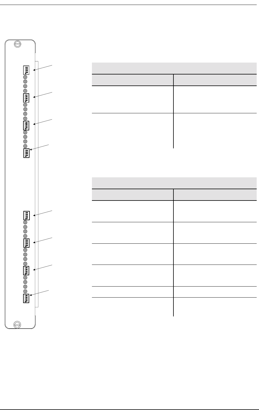
BRFXS/DPO Configuration Settings
9/24/01 9-21
Figure 9-4: BRFXS/DPO Back Plate Controls and LEDs
Table 9-3
BRFXS/DPO Back Plate Switches
Switch Function
Channel Test
(12 per card)
Applies reverse battery to
CPE loop and forces A/B bits
sent toward network to 1/1
TP Busy/Idle
(One per card)
Selects reverse (busy) or
forward (idle) battery on tip-
ground relays during trunk
processing
Table 9-4
BRFXS/DPO Back Plate LEDs
LED State Condition
OFF Idle state
(forward battery)
Green Incoming call
(reverse battery)
Yellow Call in Progress
(reverse battery)
Red Outgoing line seizure
(forward battery)
All LEDs Yellow AB 1 in trunk processsing
All LEDs Flash Red Unsupported signaling option
selected
Channel 22
Channel 21
Channel 20
Channel 19
Channel 18
Channel 17
Channel 16
Channel 15
Channel 14
Channel 13
Test 20
Test 19
Test 18
Test 17
Test 16
Test 15
Test 14
Test 13
TP Busy/Idle
Option C
Option B
Option A
Test 12
Test 11
Test 10
Test 9
Channel 12
Channel 11
Channel 10
Channel 9
Channel 8
Channel 7
Channel 6
Channel 5
Channel 4
Channel 3
Channel 2
Channel 1
Test 8
Test 7
Test 6
Test 5
Test 4
Test 3
Test 2
Test 1
TP Busy/Idle
Option C
Option B
Option A
Test 24
Test 23
Test 22
Test 21
Channel 24
Channel 23
Channel Test
Switches &
Indicators
Channels 13-16
TP Busy/Idle Switch
Channels 13-24
Channel Test
Switches &
Indicators
Channels 1-4
TP Busy/Idle Switch
Channels 1-12
Channel Test
Switches &
Indicators
Channels 5-8
Channel Test
Switches &
Indicators
Channels 9-12
Channel Test
Switches &
Indicators
Channels 17-20
Channel Test
Switches &
Indicators
Channels 21-24

Battery Reversal FXS & Dial Pulse Origination Card
9-22 9/24/01
9.7 Setting BRFXS and DPO
9.7.1 Battery Reversal FXS Loop-Start
The BRFXS/DPO card includes a setting for 2-wire FXS loop-start operation with battery reversal.
To enable this option, set Switch A on the 4-position DIP switch to ON so that cadenced ringing volt-
age is applied to the CPE loop during an incoming call (See Table 9-2). The battery is reversed during
this time. If desired, Switch B can be turned ON also to send a cadenced (2-second/ 4-second) ring-
back tone to the T1 line during incoming calls.
9.7.2 Dial Pulse Origination (DPO)
The DPO option is selected by setting Switch A to OFF so that no ringing voltage is applied towards
the CPE. If desired, Switch B can be turned ON to give a cadenced (2 second/ 4 second) ringback
tone to the T1 line during incoming calls (See Table 9-2). To indicate an incoming call, the battery to
the CPE loop is reversed. When the call ends, the battery returns to forward.
9.7.3 BRFXS/DPO Voice Channel Monitoring and Testing
The channel status LEDs on the back plate of the Access Bank II allow you to monitor the individual
BRFXS/DPO voice lines. The meaning of these LEDs is summarized above in Figure 9-4.
The channel test switches on the BRFXS/DPO back plate can be used to apply reverse battery to the
CPE loop and send A/B bits forced to 1/1 toward the T1 network. If Switch A is ON, 4 seconds of
continuous ringing voltage (85 V) are sent to the tip and ring pair of each BRFXS/DPO voice chan-
nel. In this case, you can check the operation of an individual voice channel by attaching a test tele-
phone to the Tip and Ring pair of that particular channel at the punchdown block or RJ-11
Harmonica, then switching ON the appropriate channel test switch to test that channel. If Switch B is
ON, 4 seconds of continuous ringback tone is also sent to the T1 network.
9.8 Busying Out Individual BRFXS/DPO Channels
If Switch A and Switch B are both ON, setting a channel test switch to ON has four results on the
selected channel:
1. Reverse battery is applied to the CPE loop and the A/B signaling bits sent to the network are
forced to 1/1.
2. To confirm individual channel circuit integrity, 4 seconds of continuous ringing voltage are
sent to the Tip and Ring pair. The Tip is then grounded until the channel test switch is turned
to the OFF position (to the right).

Self Test Loopbacks
9/24/01 9-23
Danger: Four seconds of continuous ringing voltage (85 V) will be present
at the Tip and Ring pair of the channel-under-test until the test telephone is
picked up to trip the ringing.
Requirement: A test telephone connected to the punch down block or RJ-11
Harmonica should ring for 4 seconds.
3. As an aid to network technicians troubleshooting audio problems, 4 seconds of continuous
ringback tone are also sent toward the T1 network.
4. After the 4 seconds of continuous ringback tone, the FXS channel will “busy out” toward the
T1 network side.
Note: Each channel test switch can provide ringing during Trunk Processing (or
even when the T1 line is disconnected).
9.9 Self Test Loopbacks
If a Self-Test is in progress and Switch A is ON, setting a channel test switch to the ON position
should have the following result:
The affected channel receives 4 seconds of continuous ringing voltage (85 V) and the LED for that
particular channel turns RED. This allows a technician to ring the telephone and verify audio tone
when it is answered.
Note: During Self Test, a RED channel LED may come on, but does not indicate a
problem.
!

Battery Reversal FXS & Dial Pulse Origination Card
9-24 9/24/01

9/24/01 10-1
Chapter 10
12-Channel FXO & Dial
Pulse Termination Card
Contents of This Chapter:
10.1 About This Chapter
This chapter describes the 12-Channel Foreign Exchange Office (FXO) and Dial Pulse Termination
(DPT) card used in the Access Bank II - SNMP, and provides information for configuring the card.
10.2 Description of the FXO Card
The FXO/DPT 12-channel analog card is an “office end” telephone line voice card designed specifi-
cally as an interface for Carrier Access Corporation’s family of Access Bank II - SNMP T1 Voice and
Data Multiplexers, which are FCC-approved digital Channel Banks and Channel Service Unit/ Data
Service Units (CSU /DSUs) for attachment of customer premise telecommunications equipment to
public network T1 (DS1) services. The FXO/DPT card provides an interface between the Tip/Ring
pair and T1 line for each of the channels on the FXO/DPT to provide FXO and DPT operation.The
“rear” end of the FXO/DPT card (opposite the connector to the LIU board in the front of the Access
Bank) has 12-channel status LEDs and one 4-pin DIP switch used to select whether the card uses
About This Chapter .................................... 1
Description of the FXO Card ...................... 1
Termination Options .................................. 2
Foreign Exchange Office Termination ....... 2
Dial Pulse Termination (DPT) .................... 3
Channel Attenuation Options ..................... 4

12-Channel FXO & Dial Pulse Termination Card
10-2 9/24/01
FXO or DPT termination. Also on the card, each individual channel has a two position switch for the
selection of ground start or loop start (see Figure 9-3) and a 6-section DIP switch to control the line
attenuation (see Channel Attenuation Options).
10.3 Termination Options
The FXO/DPT card can be configured for use as either an FXO or DPT interface card. Further, FXO
offers both ground start (GS) and loop start (LS) modes of operation. These options require the set-
ting of one switch per channel (12 per card) and one 4-position Dual Inline Package (DIP) switch per
card (see Table 10-1, and Figure 9-3). Note that in the table, a 1 indicates the switch is on, while a 0
indicates the switch is off. The slide switch on the 12-channel analog card for each channel indicates
whether that channel is set to GS or LS mode. The DIP switch determines whether the card will use
FXO or DPT termination.
Note: When DPT is selected, the large slide switches for each channel must all be
set to LS. However, when FXO termination is chosen, either LS or GS can be
selected for each channel.
Table 10-1: Termination Options and Switch Settings for the FXO/DPT
10.3.1 Foreign Exchange Office (FXO) Termination
The FXO provides private branch exchange (PBX) office end connectivity to public network T1
lines. The FXO acts as a sink for a battery source, detects ringing, provides outgoing seizure, pro-
vides and interprets A/B bit signaling to and from the T1 line, and enables two-way voice frequency
transmission.
Trunk Signaling 4-Position DIP Switch
per Card Slide Switch
per Channel
FXO Ground Start 0000 GS
FXO Loop Start 0000 LS
DPT 1000 LS
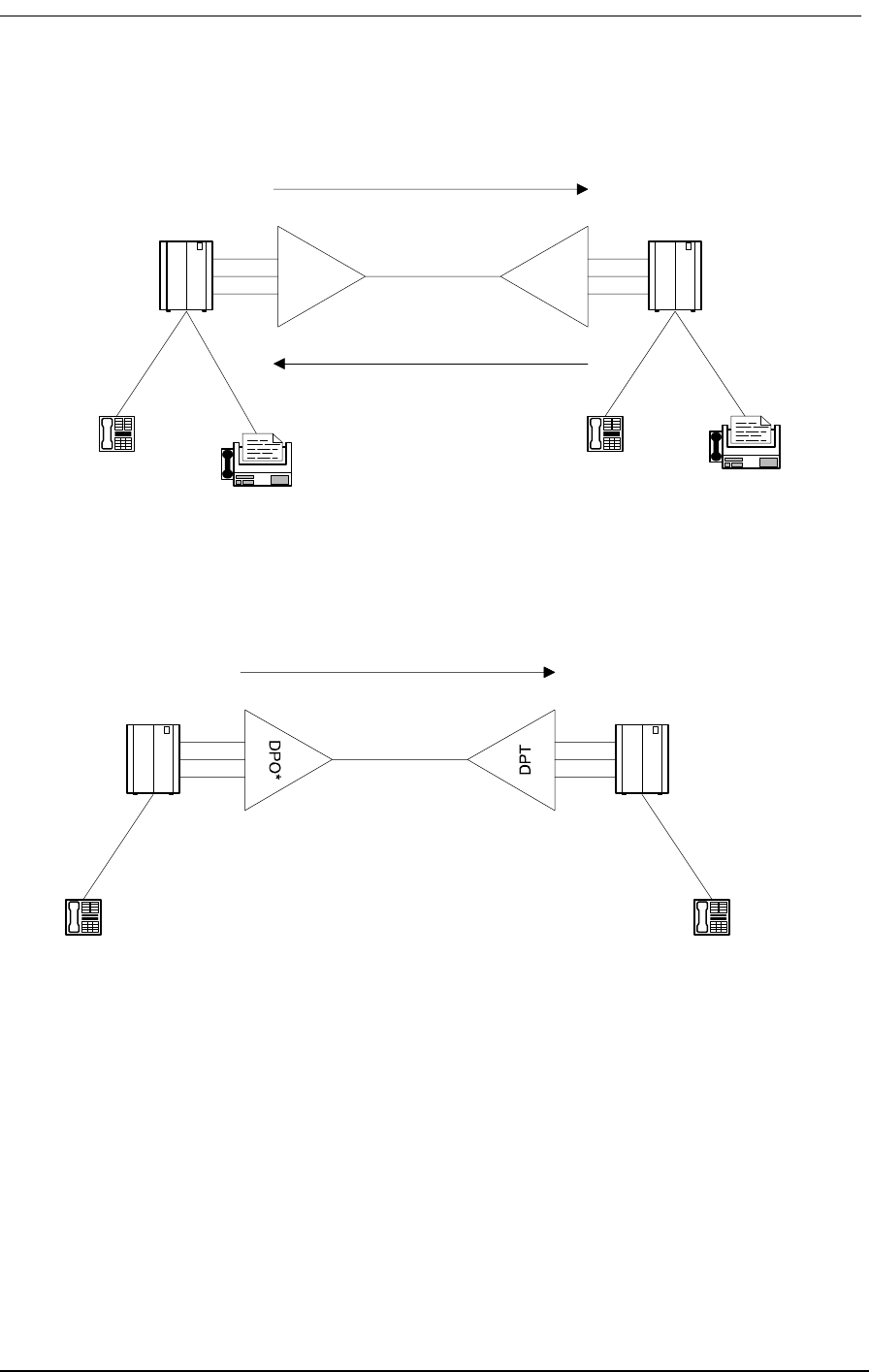
Termination Options
9/24/01 10-3
Figure 10-1: FXO Operation
________________________________________________________________________________
Figure 10-2: DPT Operation
10.3.2 Dial Pulse Termination (DPT)
In DPT mode, the FXO/DPT offers near end termination for one-way Direct Inward Dial (DID). Two-
way DID is provided by CAC’s 4 wire E&M interface. The DPT card interprets T1 signaling bits to:
• provide incoming seizure
• act as a current sink for a PBX -48V battery source
• establish an audio path
Telephone Telephone
Fax Fax
FXO
FXS
PBX
CO
Incoming
Outgoing
T1
Calling Party Called Party's
Direct Extension
PBX
CO
Direct Inward Dialing (DID)
T1
*Battery Reversal FXS/DPO 12-
Channel Analog Card

12-Channel FXO & Dial Pulse Termination Card
10-4 9/24/01
• detect battery reversal from the PBX for call progress and confirmation of call comple-
tion.
10.3.3 Channel Attenuation Options
Each of the 12 channels can be configured to attenuate both the transmit and receive audio signal.
Each channel has a 6-position dip switch; three positions for transmit attenuation and three positions
for receive attenuation. The switch positions apply different values of attenuation, and are additive (if
more than one switch is set to apply attenuation for a specific channel, the attenuation value for the
channel is the sum of those switches).
The loss is measured in decibels (dB). Note that a 3dB loss implies the average power is reduced by
50%.
The following table shows the values of attenuation applied for each switch position.
Note: Attenuation is applied when the switch is in the OFF position, and is removed
when the switch is in the ON position.
Caution: Use proper electrostatic discharge (ESD) procedures when
handling the analog cards.
Table 10-2: Transmit and Receive Attenuation Switch Values
Switch
Setting
Transmit Switch Position Loss Receive Switch Position Loss
1 2 3 4 5 6
On 0 dB 0 dB 0 dB 0 dB 0 dB 0 dB
Off -2 dB -3 dB -4 dB -2 dB -3 dB -4 dB
!
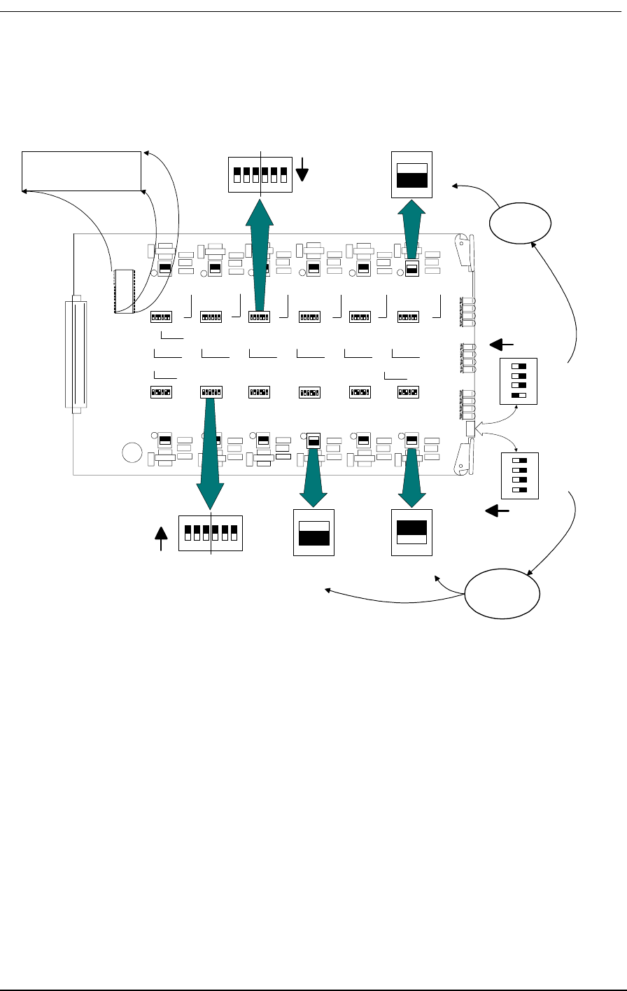
Termination Options
9/24/01 10-5
Figure 10-3: FXO/DPT Card Switch Settings
FXO V-2.2
UP (ON)
LS
GS
LS
GS
All 12 channels
are in
DPT Mode*
All 12 channels
are in
FXO Mode
Channel One
is in Loop
Start Mode
Channel 12
is in Loop
Start Mode
Channel Three
is in Ground
Start Mode
LS
GS
UP (ON)
4
3
2
1
4
3
2
1
XMT RCV
XMTRCV
ON
1 2 3 4 5 6
6 5 4 3 2 1
ON
FXO V x.x
These switches are
set for -9 dB
attenuation for both
transmit and receive
These switches are
set for 0 dB
attenuation for both
transmit and receive
In DPT Mode, all
channels must
be set
for LOOP start
In FXO Mode, each
channel can be set
for either LOOP start
or Ground start

12-Channel FXO & Dial Pulse Termination Card
10-6 9/24/01

9/24/01 11-1
Chapter 11
4-Wire E&M/TO
Configuration
Contents of This Chapter:
11.1 About This Chapter
This chapter describes how to configure the 4-wire E&M/Transmission Only (E&M/TO) 12-channel
voice card for connecting the Access Bank II - SNMP to T1 private line services that support E&M
signaling types I, II, IV and V. Also, cable information and specifications are provided at the end of
this section.
11.2 4-Wire E&M/TO Voice Card
11.2.1 Functional Description
The 4-wire E&M/Transmission Only voice card delivers 12 analog channels for connecting to private
line circuits, such as carrier PBX tie lines and 4-wire modems often found in utility, cellular, and met-
About This Chapter .................................... 1 Setting Transmit and Receive Gain.......... 9
4-Wire E&M/TO Voice Card ....................... 1 Transmit (Analog-to-Digital) Gain............. 9
Typical Applications ................................... 2 Receive (Digital-to-Analog) Gain ............ 10
E&M Signaling Conventions ...................... 3 E&M Voice Channel Monitoring ............. 10
Programming E&M Signaling Types .......... 6 E&M Normal mode cable ....................... 10
Detector Configuration ............................... 7 E&M Tandem Mode Cable ..................... 12
Normal and Tandem Cables...................... 8
Configuring Signaling Types and Trunk
Processing ................................................. 8
TP Busy/Idle Switch ................................... 9

4-Wire E&M/TO Configuration
11-2 9/24/01
ropolitan area networks. Each of the twelve E&M channels can be individually configurted to support
Signaling Types I, II, IV or V, using up to 4 signaling and transmission pairs per channel (E/M, SG/
SB, T/R, and T1/R1). This card can be configured to function as Channel Equipment (normal multi-
plexer mode) or as Switching Equipment for back-to-back Tandem applications sometimes referred
to as Reverse E&M or Pulse Link Repeater (PLR).
11.2.2 Physical Description
Like the FXS and FXO/DPT voice cards, the 4-wire E&M/TO is a 7.8” by 13.16” daughter card that
slides into the back of the Access Bank II - SNMP (AB2 - SNMP) along rails that guide a 64-pin DIN
connector to mate with a matched connector on the internal ABI Controller. The E&M/TO card
receives T1 signaling, control logic, and -48 Vdc power through this connector from the Controller
card. Because the RJ-21X Amphenol Telco connector on the ABI front control panel fails to pro-
vide enough wiring leads, it is bypassed through a 96-pin E&M signaling line connector attached on
the opposite end of the card. The E&M signaling lines (E, SG, M, SB, T, R, T1 and R1) are connected
to this high-density 96-pin DIN connector. A bank of 12 channel status LEDs are located next to the
E&M signaling line connector on the ABI back plate. Each channel has jumpers that allow the chan-
nel to be configured for E&M Types I, II, IV and V signaling. Each channel also has a 10-position
DIP switch that allows the receive and transmit attenuation to be individually set from -22 dB to +10
dB. There is also a 4-position DIP switch located next to the processor for setting regular or clear
channel E&M signaling types and selecting busy or idle during carrier failure.
11.3 Typical Applications
The major applications for the 4-wire E&M/TO voice card are E&M Tie Lines operating in either
Normal or Tandem mode. This interface also supports two-way Direct Inward Dial (DID) applica-
tions. See Figure 11-1 and Figure 11-2 below for pictorial representations of these typical applica-
tions.
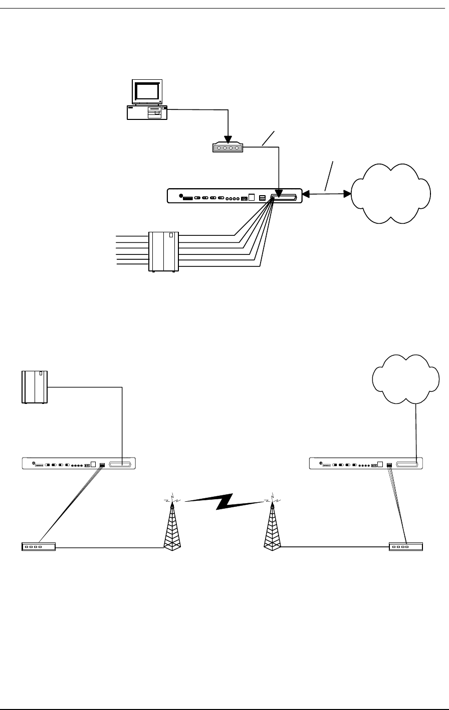
E&M Signaling Conventions
9/24/01 11-3
Figure 11-1: Normal Mode E&M Termination
Figure 11-2: Tandem Mode E&M Access to Leased Lines or Carriers
11.4 E&M Signaling Conventions
According to E&M signaling conventions, switching equipment always originates signaling on the
M-lead (the “mouth” sending toward the transmission line). The E-lead of the switching equipment
Public or Private
Network
Analog PBX
Modem for Data
Dedicated Transmission
Only
4-Wire E&M
Normal Mode
Access Bank I
T1 Network
Connection
Stations
4-Wire E&M
TO Mode
Up to 24 E&M or TO
Interfaces in 12 Channel
Increments
PBX
Radio or Micro-
Wave tower Radio or Micro-
Wave tower Radio or Microwave
Transceiver
Radio or Microwave
Transceiver
Carrier Network
Access Bank I Access Bank I
T1
T1
4-Wire E&M
Tandem
Mode
4-Wire E&M
Tandem
Mode
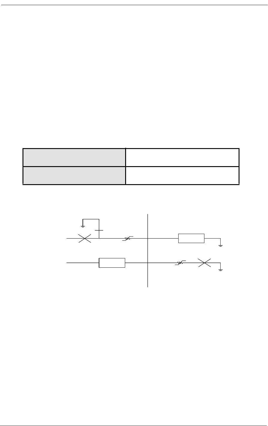
4-Wire E&M/TO Configuration
11-4 9/24/01
interface incorporates a signaling current detector (the “ear” listening to the line). The multiplexed or
carrier channel equipment always originates signaling on the E-lead coming from the transmission
line. The signaling current detector is found on the M-lead going toward the transmission line.
The 4-wire E&M/TO voice card can be optioned to operate either as channel equipment or switching
equipment. Since the Access Bank II - SNMP typically operates as a voice and data multiplexer, the
card is usually configured as channel equipment. This is referred to as tandem operation because the
card operates in tandem (i.e. back-to-back) with another transmission device.
Table 11-1 lists the generic functions performed by the Detector/Detector Return and Driver/Driver
Return when the 4-wire E&M card is configured to operate as Channel Equipment or Switching
Equipment.
Table 11-1: Detector-Driver Functions
Figure 11-3: E&M Signaling Type 1
Channel Equipment Detector is on M-lead function
Driver is on E-lead function
Switching Equipment Detector is the E-lead function
Driver is the M-lead function
M-Lead
Detector
-48V
E-Lead
Detector
-48V
M
E
E&M Type 1
Normal Mode
(Terminating)
(Channel Equipment)
Tandem Mode
(Originating)
(Switching Equipment)
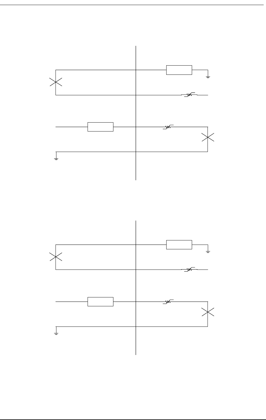
E&M Signaling Conventions
9/24/01 11-5
Figure 11-4: E&M Signaling Type 2
Figure 11-5E&M Signaling Type 4
M-Lead
Detector
-48V
E-Lead
Detector
-48V
M
E
E&M Type 2
SB
SG
Normal Mode
(Terminating)
(Channel Equipment)
Tandem Mode
(Originating)
(Switching Equipment)
M-Lead
Detector
-48V
E-Lead
Detector
-48V
M
E
E&M Type 4
SB
SG
Normal Mode
(Terminating)
(Channel Equipment)
Tandem Mode
(Originating)
(Switching Equipment)

4-Wire E&M/TO Configuration
11-6 9/24/01
Figure 11-6: E&M Signaling Type 5
11.5 Programming E&M Signaling Types
11.5.1 Jumper Switch Settings
E&M signaling types I, II, IV and V (see Figure 11-3, Figure 11-4, Figure 11-5, and Figure 11-6) are
configured by jumpers J1, J2 and J3 located on each channel. Because the signaling types are config-
ured for each channel individually, different E&M types may be mixed on the same card. The entire
card, however, must operate in either Normal or Tandem mode, which is determined by the signaling
cable used (Section 11.7, Normal and Tandem Cables). Table 11-2 (which is also printed on the 4-
wire E&M back plate) shows the proper jumper connections for each signaling type and mode.
The jumpers are blocks that make several connections simultaneously. The entire block is moved
Table 11-2: Jumper Connections by Type and Mode
E&M
Type Mode Jumper Placement
J1 J2 J3
1Normal3-458-9
1 Tandem 1-2 5 10-11
2Normal3-467-8
2Tandem1-267-8
4Normal1-267-8
4Tandem1-267-8
5Normal1-258-9
5Tandem1-258-9
M-Lead
Detector
-48V
E-Lead
Detector
-48V
M
E
E&M Type 5
Normal Mode
(Terminating)
(Channel Equipment)
Tandem Mode
(Originating)
(Switching Equipment)
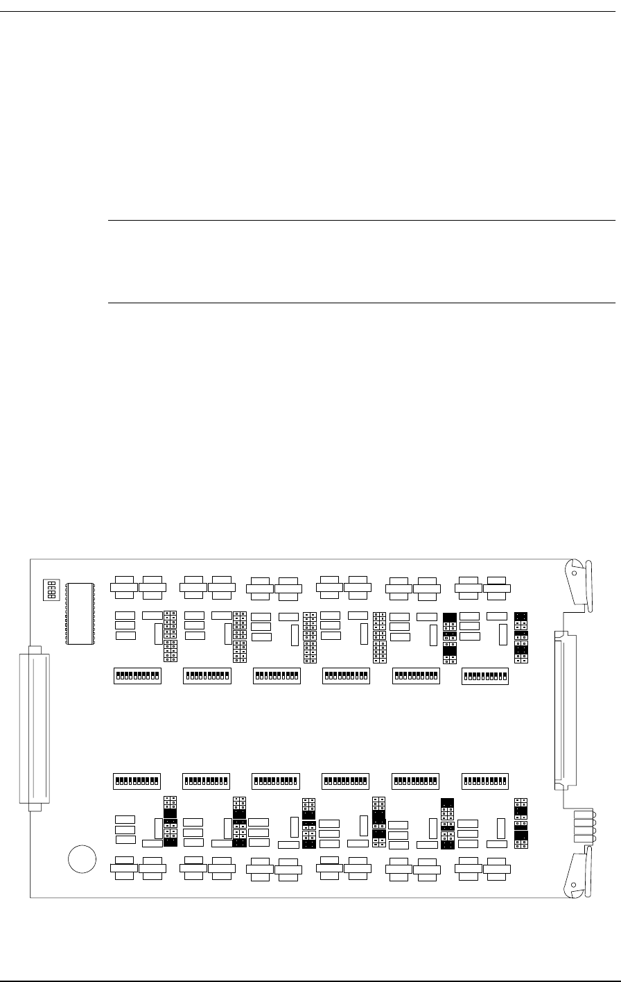
Detector Configuration
9/24/01 11-7
between the positions indicated above. This makes configuration easier by changing several connec-
tions with one move. The jumper pins are on 0.1” x 0.2” centers, making it impossible for the user to
accidentally turn the jumper 90 degrees and short -48V to ground.
Figure 11-7 shows the jumpers as they appear on the 4-wire E&M/TO card. Figure 11-7 also shows
each of the eight possible signaling combinations as complete channel setups.
Note: The jumpers do not change the actual interface pin assignments for the E&M
signaling line connector. The detector and driver functions always stay on the same
pinouts.
11.6 Detector Configuration
Jumper 1 is used to select options for configuring E&M signaling types I, II, IV and V. This jumper
connects the detector to -48 Vdc or ground. It is also used to connect the Detector Return to -48 Vdc
or ground. An on-hook signal from the far-end equipment does not cause current to flow through the
detector. When the far-end equipment applies an off-hook signal, current flows in the detector, caus-
ing the detector to be grounded. The processor receives this information and sends E&M signaling
bits to the T1 line. The table below summarizes the signaling bits sent for both detector states:
Figure 11-7: 4-Wire E&M Signaling Options
E&M V1.1
1
11
Type 1
Normal
Type 1
Tandem
Type 2
Normal
Type 2
Tandem
Type 4
Normal
Type 4
Tandem
Type 5
Normal
Type 5
Tandem
1
11

4-Wire E&M/TO Configuration
11-8 9/24/01
Table 11-3: E&M T1 Signaling
*Don’t care (0 or 1)
11.7 Normal and Tandem Cables
Individual E&M/TO voice cards require the purchase of the Normal mode or Tandem mode cables
listed below in Table 11-4. The type of cable used with the signaling line connector determines
whether all twelve channels of that card operate only in that mode. Physically, the Normal and Tan-
dem cables have one 96-pin DIN connector that plugs into the E&M card. The 96-pin DIN connector
has two 50 conductor, 24 AWG cables leading to two 50-pin Telco connectors. The Telco connectors
use standard RJ-2HX pinouts for 4-wire E&M, providing six channels per connector (twelve chan-
nels per card). Figure 11-8 and Figure 11-9 show the 4-wire E&M/TO cables.
Table 11-4: Normal and Tandem Mode Cables for 4-wire E&M/TO Card
11.8 Configuring Signaling Types and Trunk Processing
The 4-wire E&M/TO card is also equipped with a 4-position DIP switch for selecting between regu-
lar or clear channel E&M signaling types and setting busy or idle during trunk processing. This
switch is located at the front of the circuit board next to the 64-pin DIN connector.
Detector XMT Signaling Bits
A B RCV Signaling Bits
A B Driver
Off 0 0
On 1 1
0*On-Hook
1 * Off-Hook
CAC
Part Number Cable
Length Application Connectors
and Wiring List
Price
005-0004-10’ 10ft
(3.05m) Normal Mode Cable supporting E&M Types I, II,
IV, and V in Normal (Non-Tandem) Operation.
Normal operation is typical of channel equipment
such as phones, and modems, which are viewed as
terminating equipment.
C-Type 96-Pin
Male to Dual
50 Pin Telco
Male Connec-
tors, 24AWG
$190
005-0005-10’ 10ft
(3.05m) Tandem Mode Cable supporting E&M Types I, II,
IV, and V in Tandem Operation. Tandem operation
is typical of switching equipment such as PBXs and
CO switches which can be said to originate traffic.
C-Type 96-Pin
Male to Dual
50 Pin Telco
Male Connec-
tors, 24AWG
$190

TP Busy/Idle Switch
9/24/01 11-9
Table 11-5: 4-Position DIP Switch Settings
11.9 TP Busy/Idle Switch
Use switch 4 to select whether the tip-ground relays are closed (busy) or open (idle) during trunk pro-
cessing. (Trunk processing occurs when the T1 line is in an alarm or reset state.) The Busy position
(OFF) causes the tip-ground relays to be closed during a T1 alarm or reset period. The Idle position
(ON) causes the tip-ground relays to be open during a T1 alarm or reset period.
11.10 Setting Transmit and Receive Gain
The transmit (analog-to-digital) and the receive (digital-to-analog) gain for each voice channel can be
set independently using twelve 10-position DIP switches on top of the 4-wire E&M card circuit
board. Each analog channel uses a bank of ten DIP switches, with five for transmit and five for
receive. The gain from each switch is additive, with switches 1-5 providing transmit (analog-to-digi-
tal) gain of 1, 2, 4, 8 and 16 dB, respectively. Switches 6-10 set receive (digital-to-analog) gains of 1,
2, 4, 8, and 16 dB, respectively. With all five switches off, the gain is -21dB. Because the gain from
the switches is additive, any gain level between -21dB and 10dB is possible.
The digital transmission level is limited by the codec to a maximum of 3.17dBm0. The gain stages
may be set to apply up to 10dB of gain; however, the maximum level of the codec must not be
exceeded or distortion will result.
The analog transmission level may be set to a maximum 9.5dBm before distortion begins to occur.
11.11 Transmit (Analog-to-Digital) Gain
A transformer provides the analog input (T, R) from the 4-wire voice connections to the Access Bank
II - SNMP. The gain from each switch on the 10-position DIP switch is additive, with switches 1-5
providing gain of 1, 2, 4, 8 and 16 dB, respectively. To calculate the T1 transmit level, use the follow-
ing formula: T1 level = Analog Input level + åGain Switches - 21
The following is an example of setting transmit gain:
Suppose the analog input level is at +3dBm. With all switches off, the level at the T1 line is +3dBm -
21db = -18dBm0. To set a 0dBm0 level at the T1 line, switches 2 and 5 (gains 2dB, and 16dB) must
be turned on. The level at the T1 line is then:
Switch Number ON OFF
1N/ANormal E&M
2N/AN/A
3N/AN/A
4TP IdleTP Busy

4-Wire E&M/TO Configuration
11-10 9/24/01
T1 level = 3dBm + 16dB + 2dB - 21dB = 0dBm0
11.12 Receive (Digital-to-Analog) Gain
To calculate the receive level on the T1, R1 pair, use the following formula:
T1/R1 level = T1 level +åGain Switches -21dB
The following is an example of setting receive gain:
Suppose the T1 input level to codec is at -1dBm0. With all switches off, the output at the T1, R1 pair
is -1dBm -21db = -22dBm. To set a 4-wire transmission level of 0dBm, switches 7, 9 and 10 (gains
2dB, 8dB, and 16dB) must be turned on. The level at the T1, R1 pair is then:
T1/R1 level = -1dBm0 + 2dB + 8dB +16dB -21dB = 0dBm.
11.13 E&M Voice Channel Monitoring
11.13.1 Call Progress LED Indicators
A bank of LEDs on the ABI back plate are used to monitor the status of incoming or outgoing calls
on each of the twelve voice channels. When viewing the LED bank, channel 1 corresponds to the
LED in the top left hand corner. Other channels are arranged left to right, row by row (like reading a
book), so channel 12 is in the bottom right corner. The meaning of the states of these 12 LEDs are
summarized in Table 11-6.
Table 11-6: E&M Channel Status LEDs
11.14 E&M Normal mode cable
11.14.1 Description
E&M normal mode cable, 96-pin DIN female to two Telco 50-pin males.
LED State Meaning
Off Idle state
Green Analog side is Off Hook
Red Digital side is Off Hook
Yellow Analog and Digital sides are both Off Hook

E&M Normal mode cable
9/24/01 11-11
11.14.2 Cable Type
Voice grade telephone cable
25 twisted pairs of 24 AWG seven-strand copper.
Outer diameter 0.34”
Two per assembly
11.14.3 Common Connector
Female 96-pin DIN C-type connector (AMP 166873-5).
DIN performance level II
Electrical and environmental properties as per DIN 41612 and IEC 603-2
One per assembly
Backshell Kit
AMP 826196-1
One per assembly
11.14.4 Telco Connectors
Telco or Amphenol type connector (AMP 229974-4)
Two per assembly
Adjustable cable clamp (AMP 552763-2)
Two per assembly
Backshell Kit (AMP 552760-2)
Two per assembly
11.14.5 Markings
Red 1.5” long band on each cable near Telco connector
Silk screen as shown below on DIN connector backshell.
11.14.6 Length
10 feet
11.14.7 Physical Appearance

4-Wire E&M/TO Configuration
11-12 9/24/01
Figure 11-8: E&M Normal Mode Cable
11.15 E&M Tandem Mode Cable
11.15.1 Description
E&M tandem mode cable, 96-pin DIN female to two Telco 50-pin males.
11.15.2 Cable Type:
Voice grade telephone cable
25 twisted pairs of 24 AWG seven-strand copper.
Outer diameter 0.34”
Two per assembly
11.15.3 Common Connector:
Female 96-pin DIN C-type connector (AMP 166873-5).
DIN performance level II
Electrical and environmental properties as per DIN 41612 and IEC 603-2
One per assembly
Backshell Kit
AMP 826196-1
One per assembly
11.15.4 Telco Connectors:
Telco or Amphenol type connector (AMP 229974-4)
005-0004
50-Conductor, solid
strand 24 AWG
C-Type 96-Pin DIN
connector
50-Pin AMP Champ
Connectors, Male
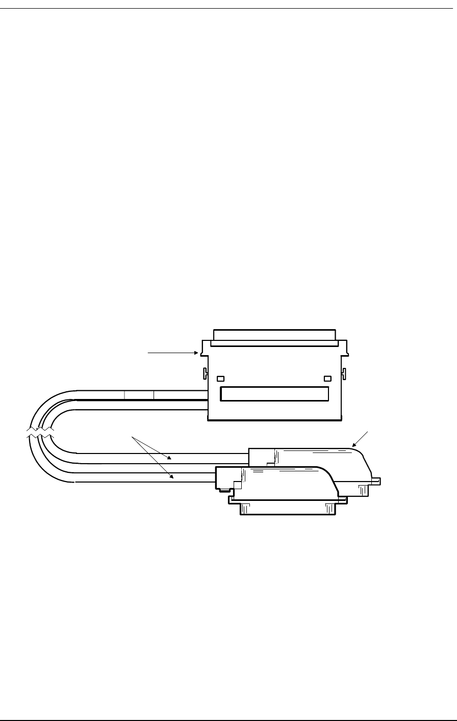
E&M Tandem Mode Cable
9/24/01 11-13
Two per assembly
Adjustable cable clamp (AMP 552763-2)
Two per assembly
Backshell Kit (AMP 552760-2)
Two per assembly
11.15.5 Markings:
Blue 1.5” long piece of heat shrink tubing on each cable near Telco connector
Silk screen as shown below on DIN connector backshell.
11.15.6 Length
10 feet
11.15.7 Physical Appearance
Figure 11-9: E&M Tandem Mode Cable
005-0005
50-Conductor, solid
strand 24 AWG
C-Type 96-Pin DIN
connector
50-Pin AMP Champ
Connectors, Male

4-Wire E&M/TO Configuration
11-14 9/24/01
Table 11-7(Part 1): Connector Pinouts for Cable P/N 005-0004
RJ2HX Punchdown Block
E&M Type I, II, IV, V
Normal Mode
Note: Telco Pinouts 1 & 26, 2 & 27, 3 & 28, etc. are twisted pairs
Telco Connector A Telco Connector B
Telco
Pinouts
Telco
Label
C type
DIN
pinouts
Card
Label
Card
Channel
Telco
Pinouts
Telco
Label
C type
DIN
pinouts
Card
Label
Card
Channel
1 R 23C R-1 1 1 R 4C R-7 7
2 R1 24C R1-1 1 2 R1 2C R1-7 7
3 SG 13A DRR1 1 3 SG 4B DRR7 7
4SB15ADETR11 4SB1BDETR77
5 R 22B R-2 2 5 R 8C R-8 8
6 R1 21B R1-2 2 6 R1 6C R1-8 8
7 SG 12A DRR2 2 7 SG 8B DRR8 8
8SB10ADETR22 8SB5BDETR88
9 R 25C R-3 3 9 R 12C R-9 9
10 R1 26C R1-3 3 10 R1 10C R1-9 9
11 SG 17A DRR3 3 11 SG 12B DRR9 9
12 SB 19A DETR3 3 12 SB 9B DETR9 9
13 R 27C R-4 4 13 R 16C R-10 10
14 R1 28C R1-4 4 14 R1 14C R1-10 10
15 SG 21A DRR4 4 15 SG 16B DRR10 10
16 SB 23A DETR4 4 16 SB 13B DETR10 10
17 R 29C R-5 5 17 R 19C R-11 11
18 R1 30C R1-5 5 18 R1 20C R1-11 11
19 SG 25A DRR5 5 19 SG 5A DRR11 11
20 SB 27A DETR5 5 20 SB 7A DETR11 11
21 R 31C R-6 6 21 R 18B R-12 12
22 R1 32C R1-6 6 22 R1 17B R1-12 12
23 SG 29A DRR6 6 23 SG 4A DRR12 12
24 SB 31A DETR6 6 24 SB 2A DETR12 12
25 -- 25 --

E&M Tandem Mode Cable
9/24/01 11-15
Table 11-7 (Part 2): Connector Pinouts for Cable P/N 005-0004
RJ2HX Punchdown Block
E&M Type I, II, IV, V
Normal Mode
Note: Telco Pinouts 1 & 26, 2 & 27, 3 & 28, etc. are twisted pairs
Telco Connector A Telco Connector B
Telco
Pinouts
Telco
Label
C type
DIN
pinouts
Card
Label
Card
Channel
Telco
Pinouts
Telco
Label
C type
DIN
pinouts
Card
Label
Card
Channel
26 T 23B T-1 1 26 T 3C T-7 7
27 T1 24B T1-1 1 27 T1 1C T1-7 7
28 E 16A DRV1 1 28 E 2B DRV7 7
29 M 14A DETC1 1 29 M 3B DETC7 7
30 T 22C T-2 2 30 T 7C T-8 8
31 T1 21C T1-2 2 31 T1 5C T1-8 8
32 E 9A DRV2 2 32 E 6B DRV8 8
33 M 11A DETC2 2 33 M 7B DETC8 8
34 T 25B T-3 3 34 T 11C T-9 9
35 T1 26B T1-3 3 35 T1 9C T1-9 9
36 E 20A DRV3 3 36 E 10B DRV9 9
37 M 18A DETC3 3 37 M 11B DETC9 9
38 T 27B T-4 4 38 T 15C T-10 10
39 T1 28B T1-4 4 39 T1 13C T1-10 10
40 E 24A DRV4 4 40 E 14B DRV10 10
41 M 22A DETC4 4 41 M 15B DETC10 10
42 T 29B T-5 5 42 T 19B T-11 11
43 T1 30B T1-5 5 43 T1 20B T1-11 11
44 E 28A DRV5 5 44 E 8A DRV11 11
45 M 26A DETC5 5 45 M 6A DETC11 11
46 T 31B T-6 6 46 T 18C T-12 12
47 T1 32B T1-6 6 47 T1 17C T1-12 12
48 E 32A DRV6 6 48 E 1A DRV12 12
49 M 30A DETC6 6 49 M 3A DETC12 12
50 -- 50 --

4-Wire E&M/TO Configuration
11-16 9/24/01
Table 11-8 (Part 1): Connector Pinouts for Cable P/N 005-0005
RJ2HX Punchdown Block
E&M Type I, II, IV, V
Normal Mode
Note: Telco Pinouts 1 & 26, 2 & 27, 3 & 28, etc. are twisted pairs
Telco Connector A Telco Connector B
Telco
Pinouts
Telco
Label
C type
DIN
pinouts
Card
Label
Card
Channel
Telco
Pinouts
Telco
Label
C type
DIN
pinouts
Card
Label
Card
Channel
1 R 23C R-1 1 1 R 4C R-7 7
2 R1 24C R1-1 1 2 R1 2C R1-7 7
3SG15ADETR11 3SG4BDETR77
4 SB 13A DRR1 1 4 SB 1B DRR7 7
5 R 22B R-2 2 5 R 8C R-8 8
6 R1 21B R1-2 2 6 R1 6C R1-8 8
7SG10ADETR22 7SG5BDETR88
8 SB 12A DRR2 2 8 SB 8B DRR8 8
9 R 25C R-3 3 9 R 12C R-9 9
10 R1 26C R1-3 3 10 R1 10C R1-9 9
11 SG 19A DETR3 3 11 SG 9B DETR9 9
12 SB 17A DRR3 3 12 SB 12B DRR9 9
13 R 27C R-4 4 13 R 16C R-10 10
14 R1 28C R1-4 4 14 R1 14C R1-10 10
15 SG 23A DETR4 4 15 SG 13B DETR10 10
16 SB 21A DRR4 4 16 SB 16B DRR10 10
17 R 29C R-5 5 17 R 19C R-11 11
18 R1 30C R1-5 5 18 R1 20C R1-11 11
19 SG 27A DETR5 5 19 SG 7A DETR11 11
20 SB 25A DRR5 5 20 SB 5A DRR11 11
21 R 31C R-6 6 21 R 18B R-12 12
22 R1 32C R1-6 6 22 R1 17B R1-12 12
23 SG 31A DETR6 6 23 SG 2A DETR12 12
24 SB 29A DRR6 6 24 SB 4A DRR12 12
25 -- 25 --

E&M Tandem Mode Cable
9/24/01 11-17
Table 11-8 (Part 2): Connector Pinouts for Cable P/N 005-0005
If your voice channels require different attenuation level settings than the factory defaults, proceed as
follows:
RJ2HX Punchdown Block
E&M Type I, II, IV, V
Normal Mode
Note: Telco Pinouts 1 & 26, 2 & 27, 3 & 28, etc. are twisted pairs
Telco Connector A Telco Connector B
Telco
Pinouts
Telco
Label
C type
DIN
pinouts
Card
Label
Card
Channel
Telco
Pinouts
Telco
Label
C type
DIN
pinouts
Card
Label
Card
Channel
26 T 23B T-1 1 26 T 3C T-7 7
27 T1 24B T1-1 1 27 T1 1C T1-7 7
28 E 16A DETC1 1 28 E 3B DETC7 7
29 M 14A DRV1 1 29 M 2B DRV7 7
30 T 22C T-2 2 30 T 7C T-8 8
31 T1 21C T1-2 2 31 T1 5C T1-8 8
32 E 11A DETC2 2 32 E 7B DETC8 8
33 M 9A DRV2 2 33 M 6B DRV8 8
34 T 25B T-3 3 34 T 11C T-9 9
35 T1 26B T1-3 3 35 T1 9C T1-9 9
36 E 18A DETC3 3 36 E 11B DETC9 9
37 M 20A DRV3 3 37 M 10B DRV9 9
38 T 27B T-4 4 38 T 15C T-10 10
39 T1 28B T1-4 4 39 T1 13C T1-10 10
40 E 22A DETC4 4 40 E 15B DETC10 10
41 M 24A DRV4 4 41 M 14B DRV10 10
42 T 29B T-5 5 42 T 19B T-11 11
43 T1 30B T1-5 5 43 T1 20B T1-11 11
44 E 26A DETC5 5 44 E 6A DETC11 11
45 M 28A DRV5 5 45 M 8A DRV11 11
46 T 31B T-6 6 46 T 18C T-12 12
47 T1 32B T1-6 6 47 T1 17C T1-12 12
48 E 30A DETC6 6 48 E 3A DETC12 12
49 M 32A DRV6 6 49 M 1A DRV12 12
50 -- 50 --

4-Wire E&M/TO Configuration
11-18 9/24/01

About This Chapter
9/24/01 12-1
Chapter 12
Diagnostics &
Troubleshooting
Contents of This Chapter:
12.1 About This Chapter
This chapter provides instructions for performing:
• Self Test Loopbacks.
• Network Loopbacks.
• Disabling external alarms.
• Fault isolation procedures for troubleshooting problems encountered while operating the
Access Bank II - SNMP.
12.2 Diagnostic Switches
The Access Bank II - SNMP System Setup and T1 Span Setup DIP switches on the Control Panel
include settings for running the self test loopbacks, enabling network loopbacks, and enabling alarm
cut-off.
About This Chapter .................................... 1 Disabling an External Alarm ..................... 6
Diagnostic Switches ................................... 1 LED Test and Status Indicators ................ 6
Self Test 1 and 2 ........................................ 2 Fault Isolation Procedures ........................ 8
Self Test Fault Indications ......................... 3 Back Plate Indications .............................. 9
1 kHz Digital Milliwatt Test Signal .............. 4 Voice Channel LED is RED ..................... 9
Network Loopback 1 and 2 ........................ 5 All Voice Channel LEDs flash RED .......... 9
T1 Line or Payload Loopbacks ................... 5 No Ringing During a Self Test ................ 10
ANSI T1.403 Remote T1 LLB .................... 5 Access Bank Shuts Down ...................... 10
Disabling an External Alarm ...................... 6

12-2 9/24/01
Note: These tests as well as additional test functions can be performed using the
MS Windows-based Remote Monitor software. For directions on performing Self
Test loopbacks and tone transmission, enabling network loopbacks, and activating
automatic Alarm Cut-Off (ACO) via the software, see the separate Remote Monitor
User’s Guide.
12.3 Self Test 1 and 2
Caution: Because Self Test is a service-disrupting procedure. Disconnect all
attached telephones prior to initiating Self Test.
12.3.1 Local Mode: OFF = No Test Tone, ON = Ringback Tone
In the Local mode, when the Self Test DIP switch 1 or 2 is set to ON and the Trunk Processing Busy/
Idle switch on each equipped FX voice card is set to Busy, the T1 output signal from T1 Span 1 or
Span 2 is disconnected from the network and looped back into the appropriate T1 receiver. See Figure
9-1. The specified T1 signal is checked internally for framing, line coding, and bipolar violations
(BPV) errors, which verifies proper operation of the Controller card. The T1 signal from the specified
span is isolated at the T1 line connection point through relay contacts to ensure that all T1 transmit
and receive circuits are tested.
The Controller then runs a card level test and injects an internally generated ringback dual tone (440
Hz +480 Hz) into all attached PCM codec channels on the T1 span specified. This allows you to ver-
ify operation of the voice channels at the punchdown block or RJ-11 Harmonica with a telephone
“buttinsky” set. For normal Access Bank II - SNMP operation, the Self Test switch must always be
left in the factory default OFF position.
The self test takes up to 16 seconds. The T1 Test 1 or 2 LED turns red during the self test sequence.
When the self test is complete, the LED should turn green. (If the Test LED remains red for longer
than 16 seconds, the unit has failed the self test.) For the self test to be valid, the Access Bank II -
SNMP must be equipped with the Controller card and at least one voice card.
To start Self Test 1 or 2 in the Local mode:
1. Locate the Self Test 1 or Self Test 2 switch on the 10-position T1 Span Setup DIP switch on
the Access Bank II - SNMP Control Panel, and set it to the Self Test position (ON).
!

Self Test Fault Indications
9/24/01 12-3
2. Verify that T1 Test 1 or T1 Test 2 LED turns green after approximately 16 seconds.
12.3.2 Card Self Test
At the start of the self test sequence, when the Controller asserts the self test bit toward the voice
card, the following events occur on a per channel basis:
• The voice card reads from the Controller and sees the self test flag at logic 1 (active).
• The received A/B signaling bits are not processed since the signaling state machine is
skipped in software.
• The outputs of the signaling state machine are forced to:
Table 12-1: Card Self Test Signaling States
12.4 Self Test Fault Indications
12.4.1 Voice Channel LED is RED during Self Test
During Self-Test, a red channel LED may come on, but does not indicate a problem.
12.4.2 No Test Tone During a Self Test
If no ringback tone is present at the drop for a particular voice channel during a self test, there may be
an open or broken pair in the voice cable. If no test tone is present on any channel during a self test,
the voice cable may be disconnected. To correct the problem:
1. Check the voice cable for a loose connection.
2. Check the voice cable for a broken/open pair.
3. If no test tone is present on a set of 12 channels during a self test, the associated voice card
may be faulty. Try replacing the voice card.
Signaling Output
Ringing voltage OFF
Tip Lead GROUNDED
Quiet Channel OFF
Ringback ON
A bit to network ZERO
B bit to network ONE
T1 Test 1 LED RED (failure)
T1 Test 2 LED RED (failure)

12-4 9/24/01
12.4.3 Remote Mode: Ringback Tone or 1 Digital Milliwatt
When the Access Bank II - SNMP is powered up in Remote mode, the tone sent during the Self Test
can consist either of the same Ringback dual tone (440 Hz +480 Hz) sent in the Local Mode or a stan-
dard 1 kHz digital milliwatt test signal. In Remote mode, Ringback tone is the default setting.
12.5 1 kHz Digital Milliwatt Test Signal
The 1 kHz digital milliwatt signal test is used to check proper DS0 channel alignment and for isolat-
ing transmission failure problems between the Access Bank II - SNMP and connected switching
equipment.
As specified in AT&T PUB 43801, the transmission of the following repetitive eight byte pattern (1E/
0B/0B/1E/9E/8B/8B/9E) in a given channel should be decoded in a properly aligned receiving termi-
nal as a 0dBm0, 1 kHz sine wave signal:
Table 12-2: Standard Digital Milliwatt Signal
12.6 Network Loopback 1 and 2
12.6.1 Local Mode: No Network Loopback or Network Loopback
Enabled
In the Local mode, setting Network Loopback 1 or 2 switch to ON causes the T1 signal received from
T1 network interface 1 or 2 to be looped back toward T1 line 1 or 2 by connecting the T1 receiver to
the T1 transmitter before the framer chip. See Figure 9-2. T1 signals are sent back to the network
exactly as they were received. No pulse stuffing, BPV correction, or framing is performed that would
corrupt T1 test patterns (such as a QRSS) received from the far end. Channel interfaces are held in the
Trunk Processing state when the Network Loopback switch is activated. The T1 Test 1 or T1 Test 2
LED on the Control Panel shows continuous yellow. All voice channel operations are suspended and
the channel status LED indicators on the back plate show continuous yellow.
Digit No. 12345678
00011110
00001011
00001011
00011110
10011110
10001011
10001011
10011110

Remote Mode: Remote T1 Line or Payload Loopbacks
9/24/01 12-5
12.7 Remote Mode: Remote T1 Line or Payload Loopbacks
In Remote mode, if the T1 line is ANSI T1.403 ESF formatted and Network Loopback detect and ESF
ANSI detect both has been enabled, the two types of loopback codes the Access Bank II - SNMP can
be configured to detect are Remote T1 Line and Remote Payload Loopback. The default setting in
Remote mode is Remote T1 Line Loopback.
12.8 ANSI T1.403 Remote T1 LLB
In a Remote T1 Line Loopback, upon receipt of a bit-oriented loopup command message consisting
of 0000111011111111 repeated at least 10 times toward the Access Bank II - SNMP in the Facility
Data Link (FDL), data recovered off the T1 line is transmitted back onto that T1 span specified with
no changes in bit sequence integrity, framing format or removal of BPVs. The Access Bank II -
SNMP should maintain the Remote LLB when it receives a loopback retention signal of
0010101011111111 sent continuously from the far-end. The loopback retention code word should be
present in the returned T1 signal. The Remote T1 LLB is released upon receipt of the bit-oriented
command message consisting of 0011100011111111, repeated at least 10 time in the FDL toward the
Access Bank II - SNMP. See ANSI T1.403-1995, Section 9.3.2.2-3 and Table 4.
12.8.1 ANSI T1.403 Remote Payload Loopback
In a Remote Payload loopback, upon receipt of a bit-oriented loopup command message consisting of
0001010011111111 repeated at least 10 times toward the Access Bank II - SNMP in the FDL, the
payload of the received T1 signal (192 information bits of a DS1 frame) is returned with no changes
in bit sequence integrity and newly generated ESF framing. The T1 Framer will correct the BPVs in
the 192 bits of payload data and re-transmit the data. The FPS framing pattern, CRC-6 calculation,
and the FDL bits are not looped back, but are instead, reinserted by the Framer. The remote PLB is
released upon receipt of the bit-oriented command message consisting of 0011001011111111,
repeated at least 10 times in the FDL.
12.9 Illustrations of Loops and Self-Tests
The following illustrations show how the loop-back tests and self-tests work. See the descriptions
above for more information about specific tests.
Figure 12-1 shows how to read the illustrations that follow.
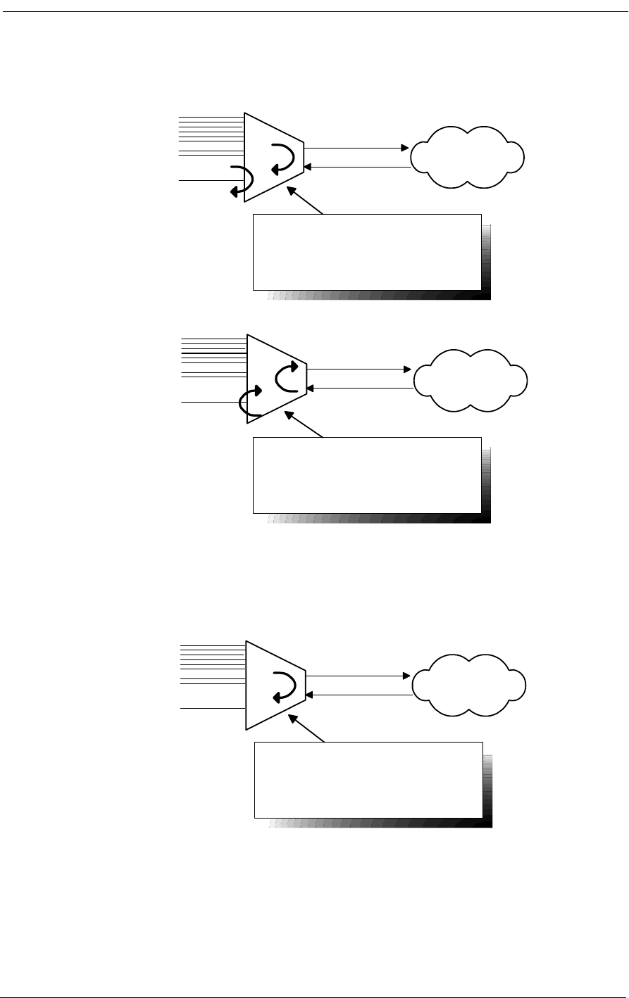
12-6 9/24/01
Figure 12-1: Loopback Legend
12.9.1 Self-Test
Figure 12-2: Self-Test
Voice
Channels
V.35
Data
Voice
Channels
V.35
Data
These are loops in the
"equipment" direction.
These are loops in the
"network" direction.
DS-1 Network
DS-1 Network
Voice
Channels
V.35
Data
Self-Test
Loop occurs at DS-1 (metallic (Tx to
Rx)),unit checks framing, no BERT
DS-1 Network
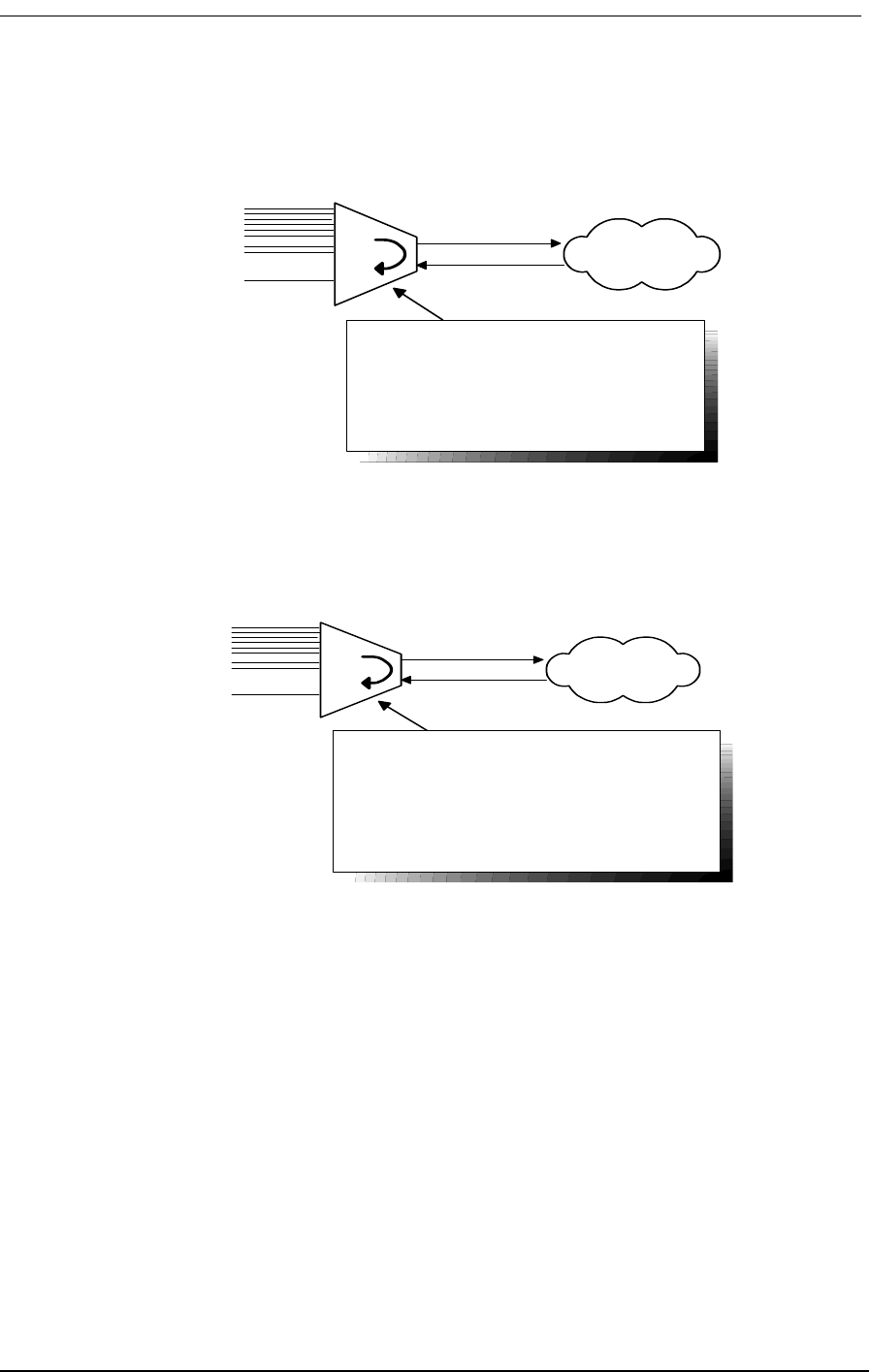
Illustrations of Loops and Self-Tests
9/24/01 12-7
12.9.2 Equipment Loopback
Figure 12-3: Equipment Loopback
12.9.3 Equipment Loopback - Payload
Figure 12-4: Equipment Loopback - Payload
Voice
Channels
V.35
Data
DS1 Equipment Loopback
Loop occurrs at DS1 (at framer), Check for
framing & errors. It metallically loops Tx to
Rx.
Commands:
loop d1 equipment line
statistics ds1 1 current
loop none
DS-1 Network
Voice
Channels
V.35
Data
DS1 Equipment Loopback Payload Only
(Reframes T1)
Loop occurs at DS1 (location), only loops 192
bits & reframes the T1. Check for framing &
errors
Commands:
loop v1 equipment line
statistics ds1 1 current
loop none
DS-1 Network
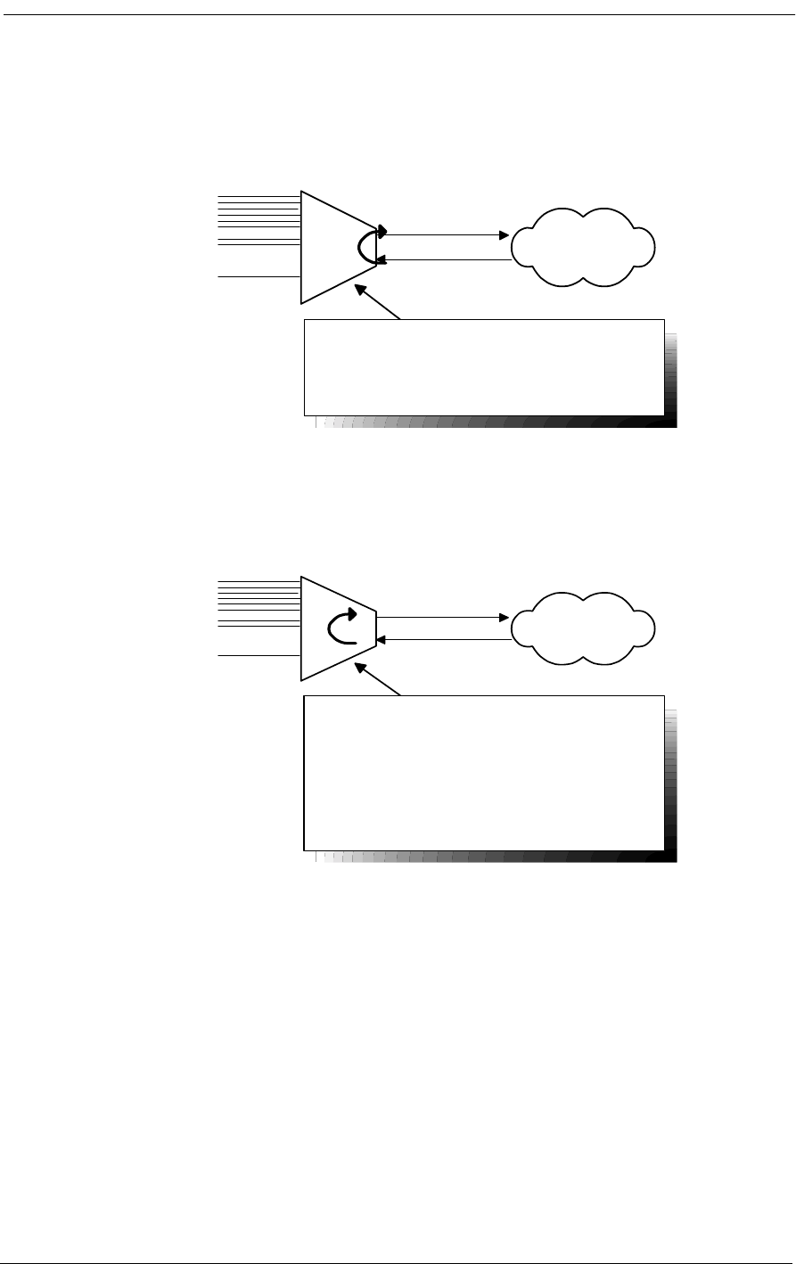
12-8 9/24/01
12.9.4 DS-1 Network Loopback
Figure 12-5: DS-1 Network Loopback
12.9.5 : DS-1 Network Loopback - Payload
Figure 12-6: DS-1 Network Loopback - Payload
Voice
Channels
V.35
Data
DS-1 Network
DS-1 Network Loop
Loops at DS-1 (at framer), have DS-1
Vendor check framing/errors
Commands:
loop d1 network line
loop none
Voice
Channels
V.35
Data
DS-1 Network
DS-1 Network Loop
Payload Only - Reframes T1
Loops at DS-1 (at framer), only loops 192 bits
and reframes the T1, corrects BPV &
recomputes CRC, have DS-1 Vendor check
framing/errors
Commands:
loop d1 network payload
loop none
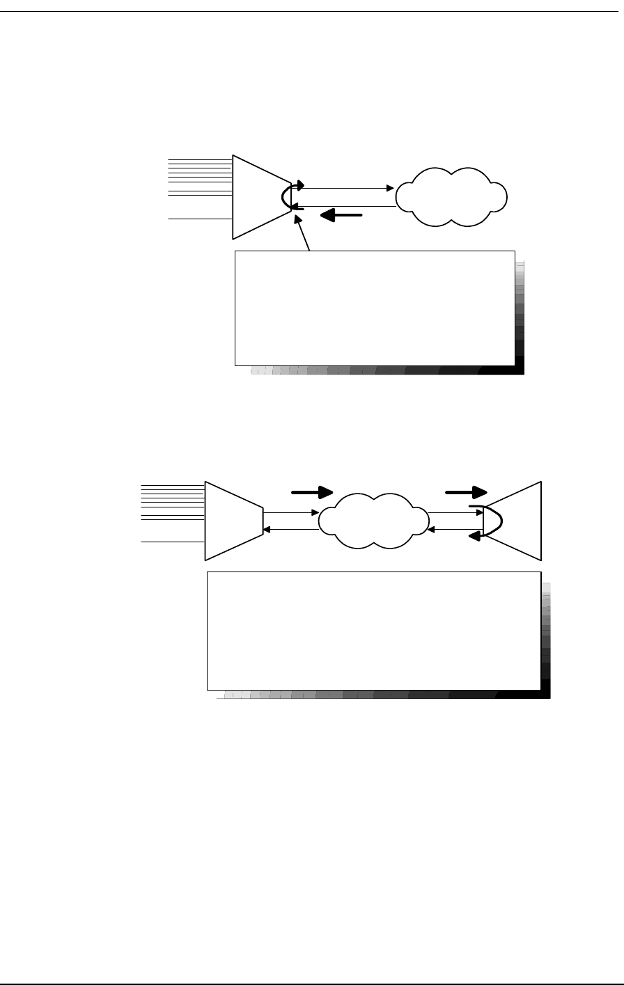
Illustrations of Loops and Self-Tests
9/24/01 12-9
12.9.6 Receiving DS-1 CSU Loopback
12.9.7 Sending DS-1 CSU Loopback
Figure 12-7: Sending DS-1 CSU Loopback
Voice
Channels
V.35
Data
DS-1 Network
Receiving DS-1 CSU Loop
Causes a network/line loopback
Loopup code sent by remote unit or network,
occurs at local DS-1 CSU.
D4 - line loop "Unframed"
ESF AT&T Line/Payload
ESF BOM Line/Loop
DS-1 vendor checks framing/errors
CSU
Loopup Code
Voice
Channels
V.35
Data
DS-1 Network
Send DS-1 CSU Loop
Local unit sends CSU loopup code, loop occurs at remote
CSU. This is a line loop only.
Check for framing/errors at local unit.
Commands:
ds1 1 send line loopup
ds1 send network QRSS
statistics ds1 1 current
ds1 1 send loopdown
CSU Loopup
Code CSU Loopup
Code

12-10 9/24/01
12.9.8 Sending DS-1 BERT Pattern
Figure 12-8: Sending DS-1 BERT Pattern
12.9.9 V.35 Equipment Loopback
Figure 12-9: V.35 Equipment Loopback
Voice
Channels
V.35
Data
DS-1 Network
Send DS-1 BERT Pattern
Local unit sends selectable test pattern, for a full T1 @
64 kBps/Channel.
Check for sync/errors across network, use "send error"
to inject one error.
Commands:
ds1 d1 send network QRSS
ds1 d1 send error
ds1 d1 send off
BERT
Pattern
BERT
Pattern
Voice
Channels
V.35
Data or
BERT
Tester
V.35 Equipment Loopback
Loop occurs at V.35 port (location).
Check for sync and errors at local data port, without BERT.
Commands:
v.35 v1 equipment line
loop none
DS-1 Network
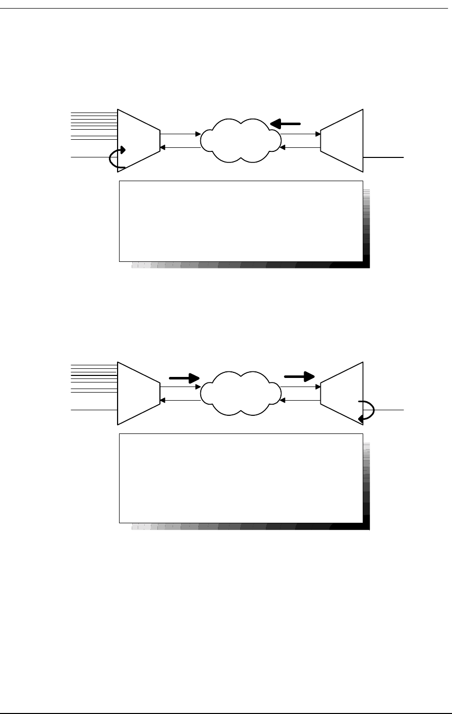
Illustrations of Loops and Self-Tests
9/24/01 12-11
12.9.10 V.35 Network Loopback
Figure 12-10: V.35 Network Loopback
12.9.11 Sending V.54 Loopback
Figure 12-11: Sending V.35 Loopback
Voice
Channels
V.35
Data
DS-1 Network
V.35 Network Loop
Loops at local V.35 port (location),
Check for sync and errors at remote data port, without
BERT.
Commands:
v35 v1 network line
loop none
V.54 Loop Up V.35 Data
Application or
BER Tester
Voice
Channels
V.35
Data
DS-1 Network
Send V.54 Loop
Local unit sends V.54 loop up code, loop occurs at remote
data port.
Check for errors on local data port, with or without BERT.
Commands:
v35 v1 send loopup
v35 v1 send network qrss
v35v1sendoff
v35 v1 send loopdown
V.54 Loop Up
Code
V.35 Data
V.54 Loop Up
Code
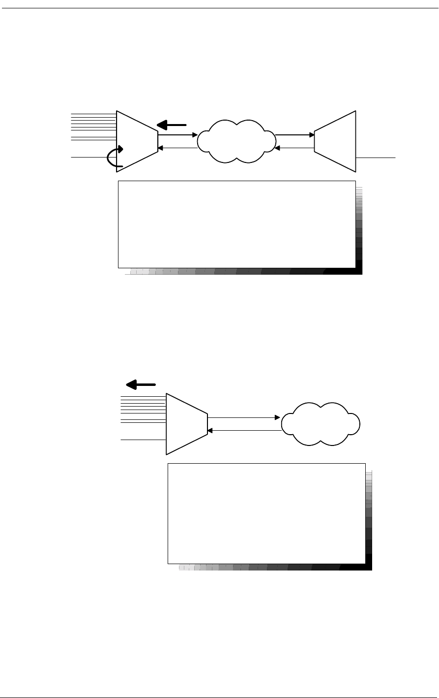
12-12 9/24/01
12.9.12 Receiving V.54 Loopback
Figure 12-12: Receiving V.54 Loop
12.9.13 Sending FX Ring or Tone
Figure 12-13: Sending FX Ring or Tone
12.10 Disabling an External Alarm
The 4-position System Setup DIP switch contains a switch labeled Alarm Cut-Off that allows you to
disable an external alarm connected to pair 25 of the 50-pin Tip & Ring jack on the Access Bank II -
Voice
Channels
V.35
Data
DS-1 Network
Receiving V.54 Loop
Remote unit or network sends V.54 loop up code, loop
occurs at local data port.
Check for errors on remote data port, without BERT.
V.35 Data
Application or
BER Tester
V.54 Loop Up
Code
Voice
Channels
V.35
Data
DS-1 Network
Sending FX Ring or Tone
Sends ringing voltage or a 1004 Hz test tone to
all the analog voice channels connected to a
specific DS-1.
Commands:
ds1 d1 send equipment ring
(or) ds1 d1 send equipment tone
(1004 Hz)
ds1 d1 send equipment off
Ringing or
1004 Hz Tone

LED Test and Status Indicators
9/24/01 12-13
SNMP Control Panel. Setting this switch to the Alarm Cut-Off position (ON) opens the alarm relay
contacts (150 Vrms, 150 mA maximum load) that close when the Access Bank II - SNMP enters an
alarm state.
Table 9-3 defines the pin functions on the 50-pin Tip & Ring jack.
Table 12-3: 50-Pin Tip & Ring Jack
12.11 LED Test and Status Indicators
Five test and status LED indicators on the Access Bank II - SNMP Control Panel provide a visual
means of identifying system, T1 line and V.35 interface troubles.
Table 12-4: T1 Line Status LEDs for T1 Span 1 and T1Span 2
Pin Location Function
26
1Tip Channel 1
Ring Channel 1
27
2Tip Channel 2
Ring Channel 2
↓↓
49
24 Tip Channel 24
Ring Channel 24
50
25 Alarm Tip Channel 25
Alarm Ring Channel 25
State Meaning
OFF Loss of T1 signal, no pulses received.
GREEN Access Bank II - SNMP is in frame
with a frame-bit error rate <10E-5.
FLASHING GREEN Access Bank II - SNMP is in frame,
but frame-bit error rate exceeds 10E-
5.
RED AIS (Unframed All Ones Signal)
received from the incoming T1 span.
FLASHING RED Access Bank II - SNMP is not syn-
chronized to the incoming T1 line,
but no AIS is being received.
YELLOW BPV errors received on the T1 line
that are not due to B8ZS line coding.
FLASHING YELLOW Yellow Alarm received from the T1
line.

12-14 9/24/01
Table 12-5: T1 Test LEDs for T1 Span 1 and 2
Table 12-6: V.35 Status LED
12.12 Fault Isolation Procedures
This section lists typical trouble symptoms that may occur while operating the Access Bank II -
SNMP and suggests appropriate corrective actions to take. Fault symptoms are organized into three
groups:
• Control Panel LED indications (system, T1 or V.35 faults)
• Back Plate LED indications (voice circuit faults)
• Other fault indications
State Meaning
GREEN Normal operations. Trunk process-
ing, self test, and network loopback
inactive.
FLASHING GREEN T1 Self Test local loopback passed.
RED T1 Self Test local loopback failed
due to one or more of the following
conditions: T1 Loss of Signal, Out of
Frame, Improper Line Code
Received, ESF or BPV errors
received.
YELLOW Channels held in Trunk Processing
for this T1 span.
FLASHING YELLOW Network loopback active for this T1
span.
State Meaning
OFF No T1 channels assigned to V.35
port.
GREEN CD (RLSD) and RTS leads active. T1
channels assigned and operative.
FLASHING GREEN V.35 in loopback to equipment.
RED CD (RLSD) lead is inactive because
assigned T1 is inoperative.
YELLOW CD (RLSD) lead active. RTS lead
inactive.
FLASHING YELLOW V.35 in loopback to T1 line.

Fault Isolation Procedures
9/24/01 12-15
Table 12-7: Control Panel LED Indications
Table 12-8: Control Panel LED Indications (continued)
Symptom Corrective Action
All LED test and status indicators are
OFF. Indicates a loss of power or excessive voltage to the
Access Bank II - SNMP. To correct the problem:
1 Verify that the Power Conversion Cube is plugged
into an active AC outlet and the power switch on the
power converter is turned on.
2 Check the circuit breaker on the Power Conver-
sion Cube.
3 If you are using an external -48 Vdc power source,
check the applied voltage. If the applied voltage is
incorrect (e.g., greater than -70 Vdc), disconnect the
external voltage source and correct its voltage output
level. The Access Bank II - SNMP circuitry will
automatically reset.
4 If the problem persists, the Access Bank II -
SNMP power supply on the Controller card has
failed. Replace the Controller card following the pro-
cedure given in the Maintenance section.
T1 Span 1 or 2 LED is RED. The Access Bank II - SNMP is not receiving a T1
signal from the line indicated. To correct this condi-
tion:
1 Check the T1 interface cable at the RJ-48C jack
and at the carrier demarcation jack. Ensure that the
cable is properly plugged in. If so, go to Step 2.
2 Run a Self Test. If the affected T1 Test LED comes
up green, replace the T1 cable. If the problem per-
sists contact the service provider.
Symptom Corrective Action
T1 Span 1 or 2 LED is YELLOW. . Bipolar Violations (BPVs) are being received
from the network. A 1-second flash indicates
that at least one BPV was received during a 1-
second interval. To correct this problem:
1 Verify the T1 Line Code 1 or 2 option selected
matches the line coding sent by the carrier.
2 If the Line Code option is set correctly and the
problem persists, contact your service provider.

12-16 9/24/01
12.13 Back Plate Indications
12.13.1 Voice Channel LED is RED (during a Self Test)
During a Self-Test, a RED voice channel LED may appear, and does not indicate a particular prob-
lem.
12.13.2 All Voice Channel LEDs flash RED
This usually indicates that an unsupported signaling option has been selected. Reconfigure the FXS
card to a supported signaling type.
12.14 Other Fault Indications
12.14.1 No Ringing During a Self Test
If no ringing signal is heard at the drop for a particular channel during a Self Test, there may be an
open or broken pair in the voice cable. If no ringing signal is heard on any channel during a self test,
the voice cable may be disconnected. To correct the problem:
T1 Test 1 or 2 LED is RED. If the T1 Test LEDs remain red for more than
16 seconds after a Self Test is initiated, the
Access Bank II - SNMP has failed the Self Test.
To correct the problem:
1 Verify that the Controller card and at least
one voice card are in place.
2 Power down the Access Bank II - SNMP for
60 seconds, power it up again, and repeat the
Self Test.
3 If the Access Bank II - SNMP fails the Self
Test again, replace the Controller card using the
procedure given in the Maintenance section.
T1 Test 1 or 2 LED flashes YELLOW. The Access Bank II - SNMP is in Network
Loopback. If this condition persists, the Access
Bank II - SNMP may not have received a loop
down code to end the network loopback To
clear this condition:
1 Be sure the Network Loopback switch is set
to OFF.
2 Set the Self Test switch to the Self Test ON
position, then back to OFF.

Access Bank II - SNMP Shuts Down for No Apparent Reason
9/24/01 12-17
1. Check the voice cable for a loose connection.
2. Check the voice cable for a broken/open pair.
3. Use Remote Monitor software to run a Self Test Loopback with the Ringback tone. If no
ringing tone is heard at the drop, the ringback generator on the Controller card may be faulty.
Replace the Controller card using the procedure given in the Maintenance section.
12.15 Access Bank II - SNMP Shuts Down for No Apparent
Reason
Internal thermal protectors automatically shut down Access Bank II - SNMP operation if the operat-
ing temperature rises above 140º F (60º C). To correct this problem:
Verify that the Access Bank II - SNMP is properly ventilated to allow for heat dissipation, and reduce
the ambient temperature if necessary. The Access Bank II - SNMP resets automatically when the
temperature is reduced below 104º F (40 C).

12-18 9/24/01

About This Chapter
9/24/01 13-1
Chapter 13
Maintenance
Contents of This Chapter:
13.1 About This Chapter
This chapter provides procedures for maintaining the Access Bank II - SNMP, including:
• “Hot swapping” individual voice cards
• Replacing the Controller card
All Access Bank II - SNMP circuits are contained on one internal Controller card and two 12-channel
voice card(s). The voice cards can be “hot swapped” with the power on, if necessary. However,
power must be disconnected before replacing the Controller card.
Procedures for replacing the card assemblies are given on the pages that follow.
Caution: Use proper electrostatic discharge (ESD) procedures when
removing and handling the Access Bank II - SNMP Controller and FXS and
FXO voice cards.
About This Chapter .................................... 1
Replacing a Voice Card ............................. 2
Replacing the Controller Card ................... 3
!

13-2 9/24/01
13.2 Replacing a Voice Card
To replace a voice card while the Access Bank II - SNMP is hot, refer to Figure 13-1, then follow
these steps:
1. Release the two thumb screws on the back plate of the Access Bank II - SNMP and remove
the plate.
2. On the voice card you wish to remove, lift the card ejector latches to release the card from its
internal connector.
3. Carefully slide the card out of the back of the Access Bank II - SNMP.
4. Check the channel attenuation loss and gain option settings on the replacement voice card
and verify they are set correctly for your intended application. If necessary, reset the channel
attenuation option settings.
5. Ensure that the replacement voice card is positioned correctly in the guide rails, then care-
fully slide the card into the slot.
6. Press the card ejector latches in towards the card until the 64-pin DIN connector on the card
mates with a matching connector on the Controller card.
7. Replace the back plate and tighten the thumbscrews.
Caution: “Hot swapping” an FXS card will cause all 24 channels to go
through Trunk Processing for 16 seconds. All calls will be disconnected and
must be dialed again after the Access Bank II - SNMP returns to its normal
operating state.
!

Replacing the Controller Card
9/24/01 13-3
Figure 13-1: Accessing the Voice Cards
13.3 Replacing the Controller Card
To replace the Access Bank II - SNMP Controller card, follow these steps:
1. Power down the Access Bank II - SNMP.
2. Disconnect power and interface cables
3. Refer to Figure 13-2 to locate the back plate of the Access Bank II - SNMP that identifies the
voice channels and any corresponding test switches. Loosen the two thumb screws and
remove the back plate.
4. Remove the chassis tray using the procedure outlined in Figure 13-2.
Warning: While sliding out the chassis tray, ensure that the components on
the circuit cards clear the Access Bank II - SNMP chassis without damage.
5. Remove the voice cards by lifting the card ejector latches and sliding the cards out of the
back of the chassis housing.
6. Remove the five screws fastening down the Controller card (see Figure 13-3) and remove the
!
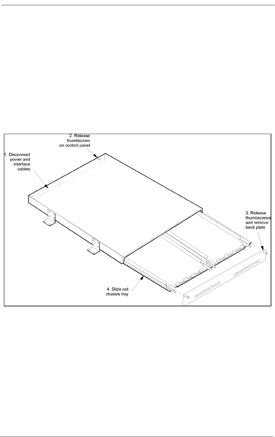
13-4 9/24/01
card.
7. Insert the new Controller card and secure it with the five screws removed in Step 7.
8. Insert the voice card(s) and slide the chassis tray back into place.
9. Replace the back plate and tighten the two thumbscrews.
10. Tighten the thumbscrews on the front Control Panel, then reattach the power and interface
cables.
11. Apply power to the Access Bank II - SNMP.
Figure 13-2: Removing the Chassis Tray

Replacing the Controller Card
9/24/01 13-5
Figure 13-3: Replacing the Controller Card

13-6 9/24/01

About This Chapter
9/24/01 14-1
Chapter 14
SNMP Management &
Command Line Interface
Contents of This Chapter:
14.1 About This Chapter
This chapter provides a general introduction to Carrier Access Corporation’s Access Bank II SNMP
and includes summaries of its:
• Simple Network Management Protocol (SNMP) Management
• Command Line Interface (CLI) Management
14.2 Local/Remote Mode Selection
The Access Bank II SNMP comes equipped with two sets of external DIP switches for selecting local
or remote control. The DIP switches must be set to the remote software control mode in order to use
SNMP, CLI, or GUI management terminals.
In the local hardware control mode, you can use these DIP switches to perform self-tests for channel
alignment, to select basic T1 hardware configuration parameters (AMI/B8ZS, D4/ESF), and to
enable detection of standard D4/ESF inband loop codes by the integral CSUs.
About This Chapter .................................... 1
Local/Remote Mode Selection ................... 1
SNMP Management .................................. 2
Command Line Interface (CLI) .................. 7
Context Sensitive Help .............................. 9
Configuration Commands ........................ 19
Status Commands ................................... 29
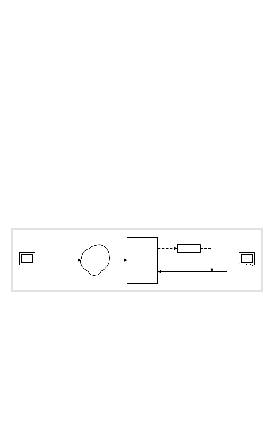
14-2 9/24/01
14.3 SNMP Management
The Access Bank II SNMP provides:
• Built-in SNMPv2 Agent software providing network statistics, information retrieval and
update, trap thresholds, and automatic transmission of trap data to Network Management
Stations.
• Application Support for Simple Network Management Protocol (SNMP) and Telnet, per
RFC 1902 through 1907. Management Information Base (MIB), per RFC 1573.
• Transport Support for Transport Control Protocol (TCP) and User Datagram Protocol
(UDP), per RFC 1213.
• Internet Support for Internet Protocol (IP) version 4, Internet Control Message Protocol
(ICMP), Address Resolution Protocol (ARP), and Reverse ARP (RARP), per RFC 1213.
• Managed Object Support for T1 interfaces, per RFC 1406. Serial RS-232 and V.35 inter-
faces for SNMPv2, per RFC 1659.
14.3.1 Local and Remote SNMP Management
The Access Bank II SNMP provides SNMP management through its Ethernet 10Base-T port. Remote
SNMP management is possible over either of the T1 lines within a V.35 user data segment, as shown
in Figure 14-1.
Figure 14-1: Local and Remote SNMP Management
14.3.2 SNMP Overview
SNMP is a complete, but simple, mechanism for network management. It works by exchanging infor-
mation between a Manager and an Agent. In this case, the Agent is inside the Access Bank II/SNMP.
The Manager is a Network Management Station (NMS), which is a computer with SNMP manage-
ment software such as HP OpenView® or Sun NetManager®.
The Agent stores the information in a Management Information Base (MIB), which contains items
such as the current status of the network interface, performance statistics, and alarms.
In general, SNMP is not concerned with controlling every feature of the many different network
objects. However, SNMP is flexible enough that it can support a wide variety of private enterprise
Router
Access
Bank II
SNMP
SNMP
Manager
SNMP in
data stream
V.35
Ethernet
10Base-T
T1
Remote
Control
SNMP
Manager
Local
Control
Frame
or IP
Network
LAN
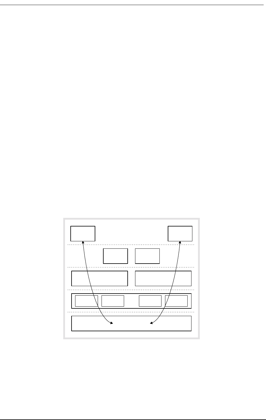
SNMP Management
9/24/01 14-3
objects with predefined MIB data structures. The Access Bank II/SNMP uses the Bellcore® standard
MIB for T1 interfaces.
Manager operations include simple “get” and “set” commands to retrieve and update MIB data in the
Agent. Normally, the Manager polls the Agent periodically to check traffic statistics. However, the
Manager can also set thresholds for traps. Traps specify network events and conditions for which the
Agent automatically sends a Telnet alarm message with trap data back to the Manager.
The Access Bank II SNMP Agent’s principle benefits are the proactive management of V.35 and
DSX-1 alarms, performance statistics, and line tests.
14.3.3 Protocols
The Manager and Agent are software applications. They communicate with each other through sev-
eral protocol layers (Figure 14-2) that are normally transparent to the user. The Access Bank II/
SNMP uses Ethernet as the physical link between the Manager and Agent. The Ethernet data can, in
turn, be carried over either of the T1 lines within a V.35 user data segment.
SNMP is an application-level protocol intended to work with the User Datagram Protocol (UDP) and
Internet Protocol (IP) suite, which includes BootP, Internet Control Message Protocol (ICMP),
Address Resolution Protocol (ARP), and Reverse ARP (RARP). The advantage of UDP is that each
message is independent; no network connections are maintained between the Manager and Agent.
Figure 14-2: Protocol Hierarchy Used In Access Bank II SNMP
Telnet
IP
SNMP
TCP UDP
Ethernet
ICMP BootP ARP RARP
Manager Agent
(many paths are possible)

14-4 9/24/01
14.3.4 Management Information Bases
The SNMP agent on Access Bank II SNMP supports the following standard MIB object groups:
Table 14-1: Supported Management Information Bases
14.3.5 Commands
The Access Bank II SNMP supports commands for the following operations described in RFC 1902
through 1907.
• GetBulkRequest
• GetNextRequest
• GetRequest
•Inform
•Report
• Response
• SNMPv2-Trap
•SetRequest
14.3.6 Statistics
The Access Bank II SNMP agent maintains statistics for the following network interface and TCP/IP
protocols:
• Ethernet Media Access Control (MAC)
• Address Resolution Protocol (ARP) for 10 entries
• Internet Control Message Protocol (ICMP)
• Internet Protocol (IP)
• User Datagram Protocol (UDP)
• Simple Network Management Protocol (SNMP)
MIB RFC Description
RFC1213 Management Information Base for Network Management of TCP/IP-based: In-
ternet MIB-II
RFC1406 Definitions of Managed Objects for the DS1 and E1 Interface Types
RFC1573 Evolution of the Interfaces Group of MIB-II
RFC1659 Definitions of Managed Objects for RS-232-like Hardware Devices using
SNMPv2
RFC 1902-
1907 Management Information Base for Version 2 of the Simple Network Manage-
ment Protocol (SNMPv2)

SNMP Management
9/24/01 14-5
• T1 interface statistics, per RFC 1406
14.3.7 Traps
The Access Bank II SNMP agent supports the following standard SNMPv2 defined traps. In the
future, enterprise specific traps will be added. Interpretations of the trap values are:
coldStart Trap
A coldStart(0) trap signifies that the sending protocol entity is reinitializing itself such that the
agent's configuration or the protocol entity implementation may be altered.
warmStart Trap
A warmStart(1) trap signifies that the sending protocol entity is reinitializing itself such that
neither the agent configuration nor the protocol entity implementation is altered.
linkDown Trap
A linkDown(2) trap signifies that the sending protocol entity recognizes a failure in one of the
communication links represented in the agent's configuration. The Trap-PDU of type linkDown
contains as the first element of its variable-bindings, the name and value of the ifIndex instance
for the affected interface.
linkUp Trap
A linkUp(3) trap signifies that the sending protocol entity recognizes that one of the communi-
cation links represented in the agent's configuration has come up. The Trap-PDU of type linkUp
contains as the first element of its variable-bindings, the name and value of the ifIndex instance
for the affected interface.
authenticationFailure Trap
An authenticationFailure(4) trap signifies that the sending protocol entity is the addressee of a
protocol message that is not properly authenticated. While implementations of the SNMP must
be capable of generating this trap, they must also be capable of suppressing the emission of such
traps via an implementation-specific mechanism.
egpNeighborLoss Trap
not supported
enterpriseSpecific Trap
A enterpriseSpecific(6) trap signifies that the sending protocol entity recognizes that some
enterprise-specific event has occurred. The specific-trap field identifies the particular trap,
which occurred. (to be implemented in the future)

14-6 9/24/01
14.3.8 Maintenance
The Access Bank II SNMP provides maintenance functions for the following SNMPv2 operations.
• Loopback operations: T1 remote line and payload. Loopback operations verify and seg-
ment operating network interface circuits.
• Fault isolation: BERT QRSS test patterns in conjunction with loopback operations.
The user may also employ standard Internet PING function tests to check the connectivity at the IP
layer.
All features of the Access Bank II SNMP are manageable through the Command Line Interface (CLI)
using a VT-100 terminal via the RS-232 port, or using a Telnet terminal session over the Ethernet
port.
All product configurations specified in RFC1406 and RFC1659 are controllable through SNMP Net-
work Management Stations, with the following exceptions: DSX-1 metallic loopback, bit error pat-
tern generation and detection, and advanced redundancy options. In future software releases, it will
be possible to add private enterprise objects that represent information specific to these Carrier
Access Corporation product features.
14.4 Command Line Interface (CLI)
The Command Line Interface gives the user the most complete management capability. The Com-
mand Line Interface is accessible via the 10BaseT Ethernet connection using the Telnet protocol or
via the RS-232 management port.
14.4.1 Local and Remote CLI Management
The Access Bank II SNMP provides CLI management through its RS-232 and Ethernet 10Base-T
ports, as shown in Figure 14-3 and Figure 14-4.
For RS-232 CLI management, a cable is connected from the RS-232 port on the Access Bank II
SNMP to a PC or laptop computer. You can use a VT-100 terminal emulation program such as
Microsoft Hyper Terminal®. CLI can also be used from a remote site by connecting the RS-232 port
to a modem and telephone line.
For Telnet CLI management, you can use a Telnet TCP/IP communications program to access CLI
through the Ethernet management port. Remote Telnet CLI operation is available using Telnet over
Ethernet or using inband T1 via the V.35 data port.
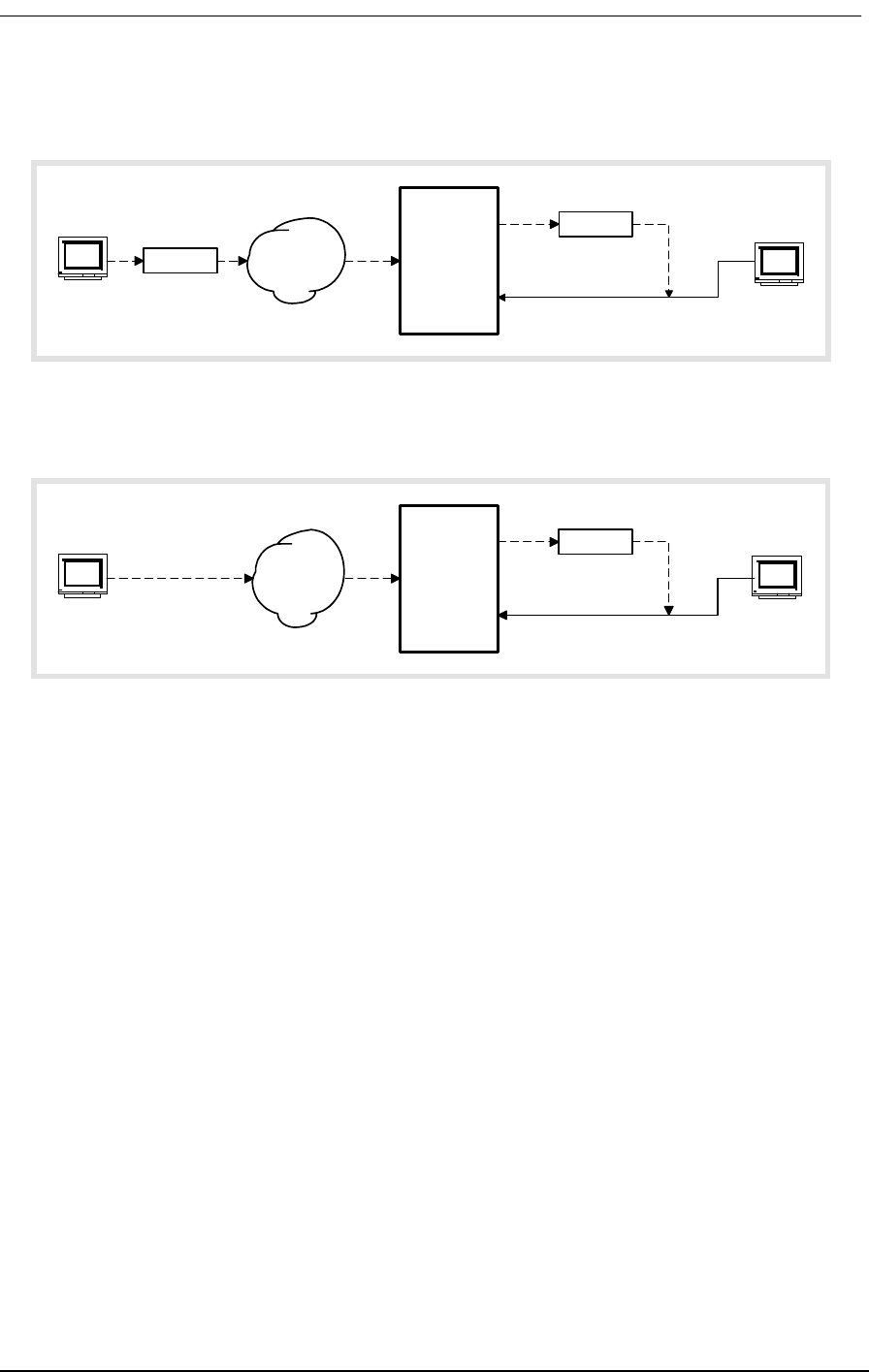
Command Line Interface (CLI)
9/24/01 14-7
.
Figure 14-3: Local and Remote RS-232 CLI Management
Figure 14-4: Local and Remote Telnet CLI Management
14.4.2 RS-232 CLI Operation
To use the Command Line Interface (CLI) with an RS-232 connection to a VT-100 terminal:
1. Connect the RS-232 cable to RS-232 management port of the Access Bank II - SNMP. The
default settings are 9600,8,1,N.
2. From your PC, run a Microsoft Hyper Terminal® session and press carriage return.
3. The Access Bank II - SNMP should display the following:
Access Bank
Boot Version 1.00
Management Version 1.29 08:38:48 12/22/1997
password:
4. Log into the management session by typing default password CAC
password:XXX
Password accepted.
Modem
Access
Bank II
SNMP
VT-100
Terminal
FXS
RS-232
T1
Modem Telephone
Network
Remote
Control
VT-100
Terminal
Local
Control
Router
Access
Bank II
SNMP
Telnet
Terminal
Telnet in
data stream
V.35
Ethernet
10Base-T
T1
Remote
Control
Telnet
Terminal
Local
Control
Frame
or IP
Network
LAN

14-8 9/24/01
Slot Card Revision
--------- --------- ---------
LIU AB-II SNMP 1.02
FX#1 FXS12 3.03
FX#2 FXS12 3.03
Span Name
--------- ----------------------------------
1) d1 “Long Distance Carrier”
2) d2 “ABI To Customer Equipment”
3) f1 “FXS To Customer Equipment”
4) f2 “Local Equipment Carrier”
Access Bank >
5. If there is no Password defined, then the following screen should be displayed.
Access Bank
Boot Version 1.00
Management Version 1.29 08:38:48 12/22/1997
Automatic Login to Access Bank :
Access Bank
Carrier Access Corporation Access Bank
Slot Card Revision
--------- --------- ---------
LIU AB-II SNMP 1.02
FX#1 FXS12 3.03
FX#2 FXS12 3.03
Span Name
--------- ----------------------------------
1) d1 “Long Distance Carrier”
2) d2 “ABI To Customer Equipment”
3) f1 “FXS To Customer Equipment”
4) f2 “Local Equipment Carrier”
Access Bank >
14.4.3 Context Sensitive Help
The Command Line interface has a context sensitive help feature that tells the operator what the com-
mand options are, and what options are available. Typing a question mark (?) at the prompt provides
a complete list of commands at the top level. Typing a question mark after a command name provides
a list of the command options at the top level. Typing help at the prompt provides a complete list of

Command Line Interface (CLI)
9/24/01 14-9
commands, including all levels of options for each command. Typing help after a command name
provides a list of the command options at all levels.
1. Type ? at the prompt to list all of the commands, as shown below.
Commands ...............Command Line Interface Help. For immediate
context sensitive help, type ? at any time.
For full command help, type “help” after
any partial command.
\ .................Enter \ to go to the top command level
aco ...............Display/Set Alarm Cutoff
alarms .............Display/Set current alarms
aps ................Display/Set Automatic Protection Switching
boot ...............(Re)Boot the system... all connections
will be dropped during initialization
clk ................Display/Set T1 Clock
config .............Set/Restore Configuration
connections ........Display Connections
craft ..............Display/Set Craft Port
date ...............Display/Set Date: date mm/dd/yyyy
dni ................Display/Set DNI (DS1 to DS1) properties
dialout ............Display/Set dialout alarm enables
ds1 [n|all] ........Display/Set DS1 n=1..2 or all DS1s
equipment ..........Display the Equipment List
event ..............Display the next 18 events
exit ...............Exit Command Line Interface
ip .................Display/Set IP Parameters
kill ...............Kill Connection Assignments
log ................Display/Set log enables
loop ...............Display/Set Loopback State
mac ................Display 6 byte MAC addr in Hex
make ...............Display/Make Connection Assignments
name ...............Display/Set Name Configuration
password ...........Change password
ping ipaddr [n] [d] Send IP Ping to ipaddr up to n times
with d ms delay between pings
rs232 ..............Display/Set Optional Data RS-232 Port
screen height [width]Display/Set CRT screen size
snmp ...............Display/Set SNMP System Group Settings
statistics .........Display Statistics
status .............Display Status of Interface(s)
telnet .............Set Telnet Session Configuration
time ...............Display/Set Time: time hr:mm:ss
trap ...............Send Warm Start Trap to SNMP
v35 ................Display/Set V.35
verbose ............Display/Set Command Fill Verbose Mode
version ............Display Version Numbers in System

14-10 9/24/01
2. Type help at the prompt to list all of the commands and options, as shown below.
Commands ............. CommandLineInterfaceHelp.Forimmediate
context sensitive help, type ? at any
time.
Forfullcommandhelp,type“help”after
any partial command.
\ ................. Enter \ to go to the top command level
aco ................. Display/Set Alarm Cutoff
off ................ Disable alarm
on ................. Enable alarm
alarms ............... Display/Set current alarms
all on|off ......... Set all alarms
sys ................ Display/Set system alarms
power on|off .. Hard reset or power on detected
brownout on|off .. Brown out detected
reset on|off .. Soft reset detected
vn ................. Display/Set alarms for V.35 #n
rts on|off .. Loss of V.35 RTS
llb on|off .. Local Loop Back detected
v54 on|off .. Remote V.54 Loop Back detected
dn ................. Display/Set alarms for ds1 #n
carrier on|off .. Loss of carrier detected
csuloop on|off .. CSU loop code received
unframed on|off .. Unframed, all 1’s received
sync on|off .. Loss of sync
yellow on|off .. Yellow alarm received
bpv on|off .. BPVs exceed 1544 in 15 min period
ses on|off .. SES exceed 10 in 15 min period
unavail on|off .. Unavailable seconds in 15 min period
fdlline on|off .. FDL line loop request received
fdlpay on|off .. FDL payload loop request received
aps ................. Display/Set Automatic Protection Switching
off ................ Disable APS mode
primary dn ......... Set either d1 or d2 as primary span
threshold n ........ Set BPV switch threshold to 10^-n, 4<=n<=6
boot ................. (Re)Boot the system... all connections
will be dropped during initialization
clk ................. Display/Set T1 Clock
primary ............ Set T1 Primary Clock Source
t11 .............. Set Clock Source to T1 #1
t12 .............. Set Clock Source to T1 #2
internal ......... Set Clock Source to internal
secondary .......... Set T1 Secondary Clock Source

Command Line Interface (CLI)
9/24/01 14-11
t11...............Set Clock Source to T1 #1
t12...............Set Clock Source to T1 #2
internal..........Set Clock Source to internal
config ...............Set/Restore Configuration
code ipaddr “path” .Load app code “path” fromTFTP server;
Specify the ipaddr and the path including
filename; System will reboot new code
download ...........(Diagnostic) Download current configura-
tion
factory ............Initialize and Download Factory Defaults
from [ipaddr “path”]Load configurationFROMXModemorTFTP
server;XModemisreliablefor19200baud
orless;FortheTFTPserver,specifythe
ipaddr and the path including filename
restore ............Restore/download last saved configuration
save ...............Save current configuration
to .................Send configuration TO XModem server
XModem is reliable for 19200 baud or less
connections ..........Display Connections
clear ..............Display Clear Channel Connections
dynamic ............Display Dynamic Connections
voice ..............Display Voice Channel Connections
craft ................Display/Set Craft Port
baud ...............Set Baud Rate
b1200.............1200 baud
b2400.............2400 baud
b4800.............4800 baud
b9600.............9600 baud
b19200............19200 baud
b38400............38400 baud
b57600............57600 baud
data ...............Set Data Size
bit7..............7 bit data
bit8..............8 bit data
dial “string” ......Set Modem Dialout String
hangup “string” ....Set Modem Hang Up String
init “string” ......Set Modem Initialization String
parity .............Set Parity
even..............Even Parity
none..............No Parity
odd...............Odd Parity
stop ...............Set Stop Bits
bit1..............One Stop Bit
bit2..............Two Stop Bits
date .................Display/Set Date: date mm/dd/yyyy
dni ..................Display/Set DNI (DS1 to DS1) properties
signal .............Display DNI Signal Type
s:c [n] opt.......Set Signal Type for [n] channels from s:c

14-12 9/24/01
0: FXS Loop or Ground Start
1: FXS Ground Start
2: FXS Loop Start
3: FXO Loop or Ground Start
4: FXO Ground Start
5: FXO Loop Start
6: E&M Immediate Start
7: E&M Wink Start
8: E&M Wink Start ANI/DNIS
9: E&M DPT
type ............... Display DNI Channel Type
s:c [n] opt ...... Set Channel Type for [n] channels from s:c
clear -- for data or bypass
voice -- for voice signaling
dialout .............. Display/Set dialout alarm enables
all on|off ......... Set all alarm enabless
pager .............. Display/Set pager device strings
““ ““ ............ Disable pager device
“phone” “msg” .... Dial phone and msg (blanks ignored)
printer ............ Display/Set printer device strings
““ ““ ............ Disable printer device
“phone” “notify” . Dial phone, report for “notify”
“DIRECT” “notify” Direct connect report for “notify”
sys ................ Display/Set system alarms
power on|off .. Hard reset or power on detected
brownout on|off .. Brown out detected
reset on|off .. Soft reset detected
vn ................. Display/Set alarm enables for V.35 #n
rts on|off .. Loss of V.35 RTS
llb on|off .. Local Loop Back detected
v54 on|off .. Remote V.54 Loop Back detected
dn .....................Display/Set alarm enables for ds1 #n
carrier on|off .... Loss of carrier detected
csuloop on|off .... CSU loop code received
unframed on|off .... Unframed, all 1’s received
sync on|off .... Loss of sync
yellow on|off .... Yellow alarm received
bpv on|off .... BPVs exceed 1544 in 15 min period
ses on|off .... SES exceed 10 in 15 min period
unavail on|off .... Unavailable seconds in 15 min period
fdlline on|off .... FDL line loop request received
fdlpay on|off .... FDL payload loop request received
ds1 [n|all] .......... Display/Set DS1 n=1..2 or all DS1s
circuitid “id” ..... DS1 Circuit ID
csu ................ Set DS1 CSU
off .............. Do not respond to CSU code
on .............. Respond to CSU code
lbo ................ Set DS1 Line Build Out

Command Line Interface (CLI)
9/24/01 14-13
dsx0|csu0.........DSX ( 0’-132’) or CSU 0.0 db
dsx133............DSX (133’-265’)
dsx266............DSX (266’-398’)
dsx399............DSX (399’-532’)
dsx533............DSX (440’-550’)
csu7..............CSU 7.5 db
csu15.............CSU 15.0 db
csu22.............CSU 22.5 db
linetype ...........Set DS1 Line Type
esf...............ESF Line Type
d4................D4 Line Type
linecode ...........Set DS1 Coding Type
ami...............AMI Line Coding
b8zs..............B8ZS Line Coding
prm ................Set DS1 Performance Monitor Message Type
ansi..............ANSI T1.403 ESF PRM
att...............AT&T 54016 ESF PRM
send ...............Send Test Data on Port
clear.............Clear Test Data Statistics
error.............Inject Single Error on Port
off...............Stop Send for Normal Operations
loopdown..........Send In-Band Remote Loop Down
loopup............Send In-Band Remote Loop Up
statistics........Display Send Statistics
network...........Send Pattern Toward Network
[p] [r].........p - optional pattern
alt - alternating 1/0
d4up - D4 loopup: 00001
d4dn - D4 loopdown: 001
ones - all ones
p1in8 - 00000001
p511 - O.153
p2047 - O.152
p2to15 - O.151
p2to20 - QRSS w/o bit stuffing
p2to23 - O.151
qrss - QRSS pattern (default)
zeros - all zeros
r - optional error rate
0 - disable errors (default)
r=1-7 - error rate of 10^-r
QRSS to net.......ds1 d1 send network > ds1 d1 send network
QRSS
p511 to net.......ds1 d2 send network p511 4
equipment ..........Send Tones to Equipment connected to ds1
[o]...............Equipment Send Usage:
o - Option for FX PCM
off - turn off test tones

14-14 9/24/01
ring - ringback to fx chans (def)
tone - 1KHz tone to fx chans
ringback to fx ... > ds1 d1 send equipment
................. > ds1 d1 send equipment ring
tone to fx ....... > ds1 d2 send equipment tone
equipment ............ Display the Equipment List
event ................ Display the next 18 events
all ................ Display the entire Event Log
clear .............. Clear the Event Log
first .............. Display the first 18 events
exit ................. Exit Command Line Interface
ip ................. Display/Set IP Parameters
addr ipaddr ........ Set IP Addr ddd.ddd.ddd.ddd
dhcp on|off ........ Set DHCP Enable
gateway ipaddr ..... Set Gateway Addr ddd.ddd.ddd.ddd
get “string” ....... Set Get Community String
mask ipaddr ........ Set Subnet Mask ddd.ddd.ddd.ddd
nms1 ipaddr ........ Set NMS1 Trap Addr ddd.ddd.ddd.ddd
nms2 ipaddr ........ Set NMS2 Trap Addr ddd.ddd.ddd.ddd
nms3 ipaddr ........ Set NMS3 Trap Addr ddd.ddd.ddd.ddd
set “string” ....... Set Set Community String
trap “string” ...... Set Trap Community String
kill ................. Kill Connection Assignments
s:c|vm|r1 [n] [i] .. All Span Connection Definitions:
s - span name: T1 = d1,d2...and FX = f1,f2...
c - channel number: 1...
n - number of channels to kill, default 1 for a single
channel
i - channel increment, default 1,
2 means every other channel, etc.
vm - V.35 span, m = 1...
r1 - User Data RS-232 span
s:c - half cnct, T1 or FX channel
All connections .... > kill all
FXO on f2 .......... > kill f2
Second half T1#1 ... > kill d1:13 12
All V.35#1 ......... > kill v1
log ................. Display/Set log enables
all on|off ......... Set all log enables
sys ................ Display/Set system log enables
power on|off .. Hard reset or power on detected
brownout on|off .. Brown out detected
reset on|off .. Soft reset detected
vn ................. Display/Set log enables for V.35 #n
rts on|off . Loss of V.35 RTS
llb on|off . Local Loop Back detected
v54 on|off . Remote V.54 Loop Back detected
dn ................ Display/Set log enables for ds1 #n

Command Line Interface (CLI)
9/24/01 14-15
carrier on|off ..Loss of carrier detected
csuloop on|off ..CSU loop code received
unframed on|off ..Unframed, all 1’s received
sync on|off ..Loss of sync
yellow on|off ..Yellow alarm received
bpv on|off ..BPVs exceed 1544 in 15 min period
ses on|off ..SES exceed 10 in 15 min period
unavail on|off ..Unavailable seconds in 15 min period
fdlline on|off ..FDL line loop request received
fdlpay on|off ..FDL payload loop request received
loop .................Display/Set Loopback State
none ...............Disable any Current Loopback
a d t ..............General Loopback Usage:
a - Access Port:
vn - for V.35 port #n
dn - for DS1 port #n
d - Direction of Loopback:
equipment - towards customer equip
network - towards network
t - Type of Loopback:
line - line loopback
payload - payload loopback
D1 toward Net ......> loop d1 network line
..................> loop d1 network payload
V1 toward Router ..> loop v1 equipment line
..................> loop v1 equipment payload
mac .................Display 6 byte MAC addr in Hex
make ................Display/Make Connection Assignments
s:c|vm|r1 s:c [n] [i]Connection Definitions:
s - span name: d1,d2...,f1,f2,...
c - channel number: 1...
n - number of channels to connect,
default 1 for a single channel
i - channel increment, default 1,
2 means every other channel, etc.
vm - V.35 span, m = 1...
r1 - User Data RS-232 span
s:c - half cnct, T1 or FX channel
D1 to FX1 ..........> make d1:1 f1:1 12
V.35 to D1 .........> make v1 d1:23 2
name .................Display/Set Name Configuration
circuitid s “id” ...Display/Set Circuit ID for span s:
d1, d2, f1, f2, v1, etc
session “prompt” ...Display/Set Session Prompt Name
system “name” ......Display/Set System Name
password .............Change password
ping ipaddr [n] [d] ..Send IP Ping to ipaddr up to n times
with d ms delay between pings

14-16 9/24/01
rs232 ................ Display/Set Optional Data RS-232 Port
baud ............... Set Async Subrate Baud Rate
b9600 ............ 9600 baud
b19200 ........... 19200 baud
b38400 ........... 38400 baud
b57600 ........... 57600 baud
data ............... Set Async Subrate Data Size
bit7 ............ 7 bit data
bit8 ............ 8 bit data
parity ............ Set Parity
even ............ Even Async Subrate Parity
none ............. No Parity
odd .............. Odd Parity
speed ............. Set Synch Speed
k56 ............. 56Kpbs
k64 ............. 64Kpbs
stop .............. Set Async Subrate Stop Bits
bit1 ............ One Stop Bit
bit2 ............. Two Stop Bits
type ............... Set User RS-232 Port Type
subrate ......... Asyncronous Subrate
sync ............. Synchronous
screen height [width]Display/Set CRT screen size
snmp ................. Display/Set SNMP System Group Settings
contact “name” ..... Set Contact Name
location “name” .... Set System Location Name
name “name” ....... Set System Name
off ............... Set SNMP Get/Set Communities private
on ................ Set SNMP Get/Set Communities public
statistics ........... Display Statistics
ds1 ................ Display ds1 Performance Statistics
[n|all] [ ........ n - span number or name, e.g. d1
t - time interval, default 15 minute
min15 = 15 minute intervals
min30 = 30 minute intervals
hour = 1 hour intervals
hour2 = 2 hour intervals
hour4 = 4 hour intervals
hour8 = 8 hour intervals
hour12 = 12 hour intervals
day = 1 day interval
current .......... Display ds1 Current Statistics
totals ........... Display ds1 Total Statistics
status ............... Display Status of Interface(s)
dip ................ Dip Switches
ethernet ........... Ethernet Interface
fx ................. FX Channel Status
icmp ............... ICMP Interface

Command Line Interface (CLI)
9/24/01 14-17
interface ..........IP Interface
leds ...............Leds on unit
signal .............FX Signal Type by Channel
snmp ...............SNMP Interface
tcp ................TCP Interface
udp ................UDP Interface
xmodem .............XMODEM Interface
telnet ...............Set Telnet Session Configuration
echo ...............Echo Telnet output on serial line
off...............Disable echo
on................Enable echo
time .................Display/Set Time: time hr:mm:ss
trap .................Send Warm Start Trap to SNMP
n up|down ..........Send Link Up or Link Down for I/F #n
v35 ..................Display/Set V.35
circuitid ..........V.35 Circuit ID
clkinv .............Clock Inversion
none..............No Clocks Inverted
rx ...............Receive Clock Inverted
rxtx..............Both Clocks Inverted
tx................Transmit Clock Inverted
cts ................CTS Signal Control
cd................CTS Follows CD Signal
high..............CTS Always High
low...............CTS Always Low
rts...............CTS Follows RTS Signal
datainv ............Data Inversion
invert .............Data Inverted
none..............Data Not Inverted
rxclk .............Receive Clock Source
internal .........Internal Clock (same as TX)
external .........External Clock
send ..............Send Test Data on Port
clear ............Clear Test Data Statistics
error ............Inject Single Error on Port
off ..............Stop Send for Normal Operations
loopdown .........Send In-Band Remote Loop Down
loopup ...........Send In-Band Remote Loop Up
statistics .......Display Send Statistics
network ..........Send Pattern to Network
[p] [r] ........p - optional pattern
alt - alternating 1/0
d4up - D4 loopup: 00001
d4dn - D4 loopdown: 001
ones - all ones
p1in8 - 00000001
p511 - O.153
p2047 - O.152

14-18 9/24/01
p2to15 - O.151
p2to20 - QRSS w/o bit stuffing
p2to23 - O.151
qrss - QRSS pattern (default)
zeros - all zeros
r - optional error rate
0 - disable errors (default)
r=1-7 - error rate of 10^-r
QRSS to net ...... v35 v1 send network
> v35 v1 send network qrss
equipment ........ Send Pattern to Equipment
[p] [r] ........ p - optional pattern
alt - alternating 1/0
d4up - D4 loopup: 00001
d4dn - D4 loopdown: 001
ones - all ones
p1in8 - 00000001
p511 - O.153
p2047 - O.152
p2to15 - O.151
p2to20 - QRSS w/o bit stuffing
p2to23 - O.151
qrss - QRSS pattern (default)
zeros - all zeros
r - optional error rate
0 - disable errors (default)
r=1-7 - error rate of 10^-r
p511 to router .. > v35 v1 send equipment p511
speed .............. Single Channel Speed
nx56 ............. 56Kb per Channel with 7 Bit Data
nx64 ............. 64Kb per Channel with 8 Bit Data
dsu ................ DSU V.54 Remote Loopback Protocol
off .............. Do not respond to in-band V.54 signals
on ............... Respond to V.54 in-band signals (default)
verbose .............. Display/Set Command Fill Verbose Mode
off ................ Disable command fill suggestions
on ................. Enable command fill suggestions (def)
version .............. Display Version Numbers in System
14.4.4 Configuration Commands
14.4.4.1 aco
Use the aco command to display, or turn on and off, the Alarm Cutoff feature.

Command Line Interface (CLI)
9/24/01 14-19
14.4.4.2 alarms
Use the alarms command to turn on and off, the Access Bank alarms.
14.4.4.3 aps
Use the aps command to set or display the status of the Automatic Protection Switching.
14.4.4.4 boot
Use the boot command to reboot the system. All calls and connections are dropped during the reboot.
Operations Type Comments
To turn the Alarm Cutoff
on
aco on
To turn the Alarm Cutoff
off
aco off
To display the status of
the Alarm Cutoff
aco
Operations Type Comments
To set all alarms on alarms all on
To set all alarms off alarms all off
To set a specific alarm on
or off
alarm
[sys|vn|dn][alarm]on|off
To see all options for alarms, type
alarm help
To display alarms alarms
Operations Type Comments
To set either d1 or d2 as
the primary span
aps primary dn
To set BPV switch
threshold to 10^-n,
4<=n<=6
aps threshold n
To display APS status aps

14-20 9/24/01
There are no options for this command. To initiate a reboot, type boot and press return.
14.4.4.5 clk
Use the clk command to set the system clock sources. The Access Bank II - SNMP allows the user to
configure a primary and secondary clock source.
14.4.4.6 config
Use the config command to save/restore the connections configuration. The Access Bank II - SNMP
allows the user to save one configuration in addition to the factory defaults in battery backed RAM.
14.4.4.7 connections
Use the connections command to save or display the current connections between spans and groups.
This command allows the user to display all static connections and group definitions being utilized
by the system.
Operations Type Comments
To set primary clock
source to T1 #1
clk primary T1 1 This sets the primary system to clock
to be derived from T1 #1. For Access
Bank II - SNMP applications, this
should be the T1 that is being received
from the Long Distance carrier.
To set secondary clock
source to T1 #2
clk secondary T1 2
To display Help clk ?
Operations Type Comments
To restore factory
configuration
config factory Resets all configurations to the factory
defaults.
To save current
configuration
config save Saves current configuration to battery
backed RAM.
To display Help config ?

Command Line Interface (CLI)
9/24/01 14-21
14.4.4.8 craft
Use the craft command to set and display all options of the craft port. This command allows the user
to customize the craft (management) interface for communication parameters and for remote and dia-
lout access.
14.4.4.9 date
Use the date command to set date in the format shown: This date is used for time stamping alarms
and events in the system.
Operations Type Comments
To display all
connections
connections Displays all connections and group
definitions.
To display bypass
connections
connections bypass Displays only bypass connections
between spans. A Bypass connection
is a nailed up configuration and
doesn’t utilize the switch state logic.
Operations Type Comments
To set the baud rate to
9.6
craft baud b9600 Sets the Baud rate to 9.6 KBps
To set bit data size 7 bit
data
craft data bit7 Sets the data size to 7 bits
To set parity to even craft parity even Sets the parity to Even
To display Help craft ?
Operations Type Comments
To configure the clock for
the current date
date 10:13:97

14-22 9/24/01
14.4.4.10dni
Use the dni command to set the DNI properties for voice channels.
14.4.4.11dialout
Use the dialout command to set and display enabling for the dialout alarms.
14.4.4.12 ds1
Use the ds1 command to setup one or all the DS1 interfaces. The command specifies the interface
number (1-2) and the setting to apply. The ds1 command followed by the interface number will dis-
play the current configuration.
Operations Type Comments
To set signal type for n
channels from s:c
dni s:c [n] opt
To display signal type dni signal
To set DNI channel type dni type s:c [n] opt
To display DNI channel
type
dni type
Operations Type Comments
To set all dialout alarms
enabled
dialout all on To see all dialout alarm enabling
options, type dialout help
To display dialout alarm
enabling
dialout
Operations Type Comments
To display the current
settings of ds1 1
ds1 1 Displays the current setting for T1 #1.
To display Help ds1 ?

Command Line Interface (CLI)
9/24/01 14-23
14.4.4.13 event
Use the event command to display or clear the event log.
14.4.4.14 exit
Use the exit command to end the current management session.
14.4.4.15 ip
Use the ip command to set and display the ip addresses for an SNMP management session This com-
mand is used to configure the system for SNMP and Telnet access.
Operations Type Comments
To display the next 18
events
event
To display the entire
event log
event all
To display the first 18
events
event first
To clear the event log event clear
Operations Type Comments
To end current session exit Ends current session
Operations Type Comments
To configure the Access
Bank SNMP parameters
ip addr 192.168.0.220 Configures the IP address
To verify configuration
using the show command
ip Displays all current IP related
parameters.
To show Help ip ?

14-24 9/24/01
14.4.4.16 kill
Use the kill command to remove time slot connections. This command is used to kill static connec-
tions and group definitions.
14.4.4.17 loop
Use the loop command to display, disable and enable loopbacks.
14.4.4.18 mac
Use the mac command to display the six-byte MAC address in hexadecimal.
14.4.4.19 make
Use the make command to configure static connections and group definitions.
Operations Type Comments
To remove a bypass
connection on T1 #1
kill bypass d1:24 Kills the connection for slot 24 on T1
#1
To display command
Help
kill ?
Operations Type Comments
To set a line loopback
towards the network on
ds1 1
loop d1 network line Puts T1 #1 in network line loopback.
To verify loopback status loop
To display Help loop ?

Command Line Interface (CLI)
9/24/01 14-25
14.4.4.20 name
Use the name command to set or display names of circuit IDs, session prompt, and system name.
14.4.4.21 password
Use the password command to change the password.
14.4.4.22 ping
Use the ping command, to test whether or not the management node or other network devices are
reachable on the network.
Operations Type Comments
To make bypass for
group v1 in ds1 #2
channels 1 and 2
make bypass v1 d2:1 2 Configures a v.35 data connection on
channels 1 and 2 of T1 #2
To make group
assignment for group b in
fxs #2 channels 1 to 12
make group b f2:1 12 Configures voice card channels 1..12
to group B.
To display Help make ?
Operations Type Comments
To set citcuit id for span s name circuitid s “id” d1, d2, f1, f2, v1, etc.
To set the session prompt
to a required string
name prompt “prompt”
To set the system name name system “name”
Operations Type Comments
To change the password password “password”

14-26 9/24/01
14.4.4.23 rs232
Use the rs232 command to configure the RS232 port. To see all the options for this command, type
rs232 help.
14.4.4.24 screen height
Use the screen height command to set or display the current display parameters.
14.4.4.25 snmp
Use the snmp command to configure the SNMP system group settings. To see all the options for this
command, type snmp help.
14.4.4.26 telnet
Use the telnet command to configure the echo for the telnet sesson. The echo can be turned on and
off.
14.4.4.27 time
Use the time command to set time in the format shown: The time is used to accurately time stamp
Operations Type Comments
To validate that a node
on the network can be
reach via the Access
Bank II - SNMP
ping 192.127.20.10 Sends one Ping to the indicated ipaddr
To send IP ping 4 times
with 50 ml delay
between pings
ping 192.127.20.10 4 50 Sends 4 Pings to the indicated ipaddr
with 50 ms delay between pings
To display Help ping?
Operations Type Comments
To display current screen
parameters
screen height

Command Line Interface (CLI)
9/24/01 14-27
event and alarm logs.
14.4.4.28 trap
Use the trap command to send a warm start trap to SNMP, or to send a link up or down trap to an
interface.
14.4.4.29 snmp
Use the snmp command to set and display SNMP System Group settings for RFC-1213.
Operations Type Comments
To configure the clock for
the time
time 08:04:00
To display date & time date
Operations Type Comments
To send a warm start trap
to SNMP
trap
To send a link up trap to
an interface
trap n up n is the interface number (1 or 2)
To send a link down trap
to an interface
trap n down
Operations Type Comments
To set the system contact
string to your name
snmp contact "John Doe" Sets system contact name to John Doe.
To set the location
identifier
snmp location " CAC :
5395 Pearl Parkway,
Boulder CO 80301”
Sets system locations
To set the node name
identifier
snmp name “Access
Bank ”
To display Help snmp

14-28 9/24/01
14.4.4.30 v35
Use the v35 command to configure parameters for the V.35 data port to be accessed by the SNMP
manager via RFC-1659.
14.4.5 Status Commands
14.4.5.1equipment
Use the equipment command to display the hardware equipment configuration within the Access
Bank.
Operations Type Comments
To set the circuit ID to
“V.35 - 1”
v35 circuitid “V.35 - 1” Sets the Circuit Id for the V.35 port
To set clock inversion to
receive clock inverted
v35 clkinv rx Sets the receive clock to be inverted.
To set CTS to follow
RTS signal
v35 cts rts Sets CTS to follow RTS signal
To set data inversion v35datainv invert Sets the V.35 data to be inverted.
To set receive clock
source to be internal
v35 rxclk internal Sets thte system to use the Internal
Clock.
To set the speed to be
nx56
v35 speed nx56 Sets the data raste to Nx56 KBps
To display Help v35 ?
Operations Type Comments
To display the equipment
list
equipment Displays a list of the current installed
hardware and Firmware revision
levels.

Command Line Interface (CLI)
9/24/01 14-29
14.4.5.2 log
Use the log command to display the current alarm history log.
14.4.5.3 statistics
Use the statistics command to display ds1, channel and group performance.
14.4.5.4 status
Use the status command to display the status and performance data of the different interfaces sup-
ported by the Access Bank.
Operations Type Comments
To display the alarm
history log
log Index Time Date Alarm
1 00:03:06 01/01/96 Log in
0 00:00:00 01/01/96 Power on
Operations Type Comments
To display the ds1 1
performance
statistics ds1 1 Displays 15 minute interval statisitics
for DS1 #1
To display the channel
utilization of stack 1,
channel 2
statistics channel d1:2 Displays current state of channel 2 on
T1 #1
To display the group
utilization of group 2
statistics group 2
To display Help statistics ?

14-30 9/24/01
Operations Type Comments
To display the status of
the interfaces
status all Displays the status of all the interfaces
To display the status of
the Ethernet Interface
status ethernet Displays status and performance
numbers for the ethernet Interface
To display the status of
the IP interface
status interface Displays the current performance and
status for the IP layer of the
Management protocol stack.
To display the status of
the SNMP interface
status snmp
To display Help status ?
GLOSSARY
10Base-T: 10Base-T is an IEEE standard for operating Ethernet local area networks (LANs) on twisted-
pair cabling using the home run method of wiring (the same as the phone company uses) and a wiring hub
that contains electronics performing similar functions to a central telephone switch. The full name for the
standard is IEEE 802.3 10Base-T.
AIS (Alarm Indication Signal): Also known as a “Blue Alarm Signal” or “All Ones Keep Alive,” an AIS
is an unframed all ones bit pattern sent by equipment at the far end to indicate that an alarm condition exists
upstream in a circuit leading to the downstream equipment. Keep-alive signals are required by the network
facilities to prevent oscillation of the line repeaters which causes interference (i.e. cross-talk and bleeding)
within adjacent channels.
AMI (Alternate Mark Inversion): An AMI encoded signal is a bipolar pseudo-ternary signal conveying
binary digits (bits) in which successive “marks” are normally of alternating, positive and negative, polarity.
This is the traditional method of line encoding used with bipolar DS1 (T1) signals. However, use of AMI
does not preclude long strings of zeros being sent in the signal entering the public network from the DTE in
violation of the pulse density requirements mandated in Part 68 of the FCC Rules and/or AT&T Publication
62411.
ANI (Automatic Number Identification): ANI is a service available from the telephone company on
certain links that identifies the phone number of the caller to an attached computer telephony system.
B8ZS(BINARY 8-ZERO SUBSTITUTION): This line coding scheme is one of the methods used to avoid
long strings of zeros in a bipolar DS1 signal entering the network from the DTE. Every string of eight zeros
is replaced by a special code (token) for transmission over networks that are sensitive to long strings of ze-
ros. The code contains a pattern of bipolar violations that is identified by the recipient and then removed in
the decoding process to recreate the original string of zeros. This particular method of line coding is the
evolving standard, but one that is not yet fully supported by all carriers.
BIT ERROR RATE (BER): The ratio of bits received in error to total bits transmitted. The time over which
this rate is calculated is not inherent to the definition of BER and, therefore, can be separately specified.
BERT (BIT ERROR RATE TESTER): A test instrument for performing Bit Error Rate testing on a T1
line. See BER.
BLUE ALARM SIGNAL: See AIS.
BPV (BIPOLAR VIOLATION): A violation of the T1 bipolar AMI transmission pattern in which succeed-
ing “ones” (pluses) are sent at opposite polarities. A BPV normally indicates a transmission error. However,
B8ZS patterns contain bipolar violations, which are not counted as errors.
CENTRAL OFFICE (CO): Telephone company facility where subscribers’ lines are joined to switching
equipment for connecting other subscribers to each other, locally and long distance.
CHANNEL SERVICE UNIT: See DSU/CSU
CONNECTION: A connection is a logical linkage between timeslots on a span or between spans.
CROSSTALK: Crosstalk occurs when you can hear someone you did not call talking on your telephone
line to another person you did not call. You may also only hear half the other conversation (i.e. just one per-
son speaking). There are several technical causes for crosstalk relating to cable placement, shielding and
transmission techniques.
CUSTOMER PREMISES EQUIPMENT (CPE): Items of telecommunications equipment, such as key
systems, PBXs, answering machines, and CSU/DSUs, which reside on the customer’s premises past the net-
work interface.
CYCLICAL REDUNDANCY CHECK (CRC): A check sum indicator based on the remainder of a poly-
nomial calculation performed on the transmitted data that is used to verify, with some fixed probability of
correctness, whether that data was transmitted.
D4 SUPERFRAME (SF) FRAMING FORMAT: The most popular framing format in the T1 environ-
ment. Its name stems from the way framing is performed in the D-series of channel banks from AT&T.
There are 12 separate 193-bit frames in a superframe. The D4 framing bit is used to identify both the channel
and the signaling frame. In D4 framing, signaling for voice channels is carried inband by every channel
along with the encoded voice. “Robbed bit signaling” is a technique used in D4 channel banks to convey
signaling information. With this technique, the eighth bit (least significant bit) of each of the 24 8-bit
timeslots is “robbed” every sixth frame to convey voice related signaling information (on-hook, off-hook,
etc.) for each voice channel.
DATA SERVICE UNIT: See DSU/CSU
DATA TERMINAL EQUIPMENT: See DTE
DCE (DATA CIRCUIT-TERMINATING EQUIPMENT):
DIRECT INWARD DIALING (DID): The ability for a caller outside a company to call an internal exten-
sion without having to pass through an operator or attendant. In large PBX systems, the dialed digits are
passed down the line from the Central Office (CO). The PBX then completes the call.
DIGITAL ACCESS & CROSS-CONNECT SYSTEM (DACS): A digital switch for routing and switch-
ing T1 lines (and individual DS0 channels within T1 lines), among multiple T1 ports. It performs all the
functions of a normal switch, except connections are typically set up in advance of a call, not together with
a call, as in most, low bandwidth voice-band voice and data communications systems. A DACS is basically
a manual T1 switch. The Windows-based Remote Monitor software program can be used to implement DS-
0 DACS functionality in the Access Bankô II.
DIP (DUAL INLINE PACKAGE) SWITCH: A tiny switch attached to a printed circuit board with semi-
permanent settings that usually requires a ball point pen or small screwdriver to change. There are only two
settings - ON or OFF (1 or 0). In the case of the ABII, configurations set by the DIP switches can be mod-
ified later through the MS Windows Remote Monitor software installed on a PC.
DIRECT OUTWARD DIALING (DOD): The ability to dial directly from an extension without having to
go through an operator or attendant. In PBX and hybrid phone systems, you dial 9, listen to a dial tone, and
then dial the outside number you want to reach.
DNIS (DIRECTORY NUMBER IDENTIFICATION SERVICE): DNIS is a feature of 800 and 900 lines
that provides the number of the caller dialed to reach the attached computer telephony system. Using DNIS
capabilities, one trunk group can be used to serve multiple applications. The DNIS number can be provided
in a number of ways, inband or out-of-band, ISDN or via a separate dedicated data channel.
DPO (DIAL PULSE ORIGINATION) CHANNEL UNIT
DPT (DIAL PULSE TERMINATING) CHANNEL UNIT
DROP & INSERT (D&I): As applied to T1, D&I refers to the process whereby one DS-0 channel is de-
multiplexed out of the DS-1 synchronous bit stream at one port of a digital channel back and another DS-0
inserted back in. The Windows-based Remote Monitor software program can be used to perform D&I on
individual channels between two T1 lines connected to the Access Bankô II.
DSU/CSU (DATA SERVICE UNIT/CHANNEL SERVICE UNIT): A device terminating a digital chan-
nel on a customer’s premises where it performs line coding, line conditioning and equalization functions
while responding to the receipt of loopback codes sent from the Central Office (CO) A DSU/CSU sits be-
tween the digital line coming in from the CO and devices such as channel banks or data communications
devices.
DSX (DIGITAL SYSTEM CROSS-CONNECT frame): A bay or panel to which T1 lines and DS1 cir-
cuit packs are wired that permits cross-connections by patch cords and plugs. A DSX panel is used in small
office applications where only a few digital trunks are installed.
DTE (DATA TERMINAL EQUIPMENT): In the EIA/TIA 232E standard specification, the RS232 inter-
face is connected between the DCE (Data Circuit-Terminating Equipment) and the DTE. The main differ-
ence between the DCE and the DTE is the pins two and three are reversed. The ABII uses an RS-232 port
for management and asynchronous and synchronous data transmission.
DTMF (DUAL TONE MULTIFREQUENCY SIGNALING): A method of signaling in which a combina-
tion of two frequencies out of a possible eight are used to transmit numerical address information. The eight
possible frequencies are 697 Hz, 770 Hz, 852 Hz, 941 Hz, 1209 Hz, 1336 Hz, 1477 Hz, and 1633 Hz.
E&M SIGNALING: A signaling arrangement that uses separate leads, called respectively the E lead and
the M lead, for the signaling and voice signals. The M lead (derived from ‘Mouth’) transmits ground or bat-
tery to the distant end of the circuit, while incoming signals are received as either a grounded or open con-
dition on the E (derived from ‘Ear’) lead. The E&M tie trunk interface functions as a de facto standard in
the PBX - T1 multiplexer Telco environment.
ESF (EXTENDED SUPERFRAME FORMAT):
FACILITY DATA LINK (FDL): The 4 Kbps channel used to transmit supervisory
FOREIGN EXCHANGE CHANNEL UNIT - OFFICE END (FX0)
FOREIGN EXCHANGE CHANNEL UNIT - STATION END (FXS)
FRAME RELAY ACCESS DEVICE (FRAD):
FXSDN (FXS SOFTWARE-DEFINED):
LINE INTERFACE UNIT (LIU): Typically, a controller device in a D-type channel bank, such as the CAC
Access Bankô II, that incorporates a controller, channel service unit (CSU), ringing generator and power
converter on a single card to interface between the T1 network and the analog functions of the channel bank.
PBX (PRIVATE BRANCH EXCHANGE):
PERFORMANCE REPORT MESSAGE (PRM):
PLAR (PRIVATE LINE AUTOMATIC RINGDOWN): A leased voice circuit that connects two single
telephone handsets together. Whenever either handset is lifted, the other instrument automatically rings.
PSTN (PUBLIC SWITCHED TELEPHONE NETWORK): As used by the ITU-T, PSTN is simply an
abbreviation for the local phone company
QRSS (QUASI-RANDOM SIGNAL SEQUENCE): A standard test pattern generated by a 20-bit linear
feedback shift register used during loopback and BER testing to stress test the continuity and integrity of a
T1 circuit by simulating live data traffic. Generates every combination of 20-bit words, repeats every
1,048,575 bits, and suppresses consecutive zeros to no more than 14. Contains high density sequences, low
density sequences, and sequences that change from low density to high density and vice versa.
RING BACK TONE: An interrupted low tone indicating that the called telephone is ringing. This tone is
generated by a device at the Central Office (CO) and may bear no relationship to the sound the phone at the
other end is emitting - or not emitting.
RING GENERATOR: A component of virtually all phone systems, including the Access Bankô II, that
supplies the power to ring the bells inside phones, typically 90 volts AC at 20 Hz.
RINGER EQUIVALENCY NUMBER (REN): Part of the FCC certification number approving a tele-
phone terminal product for direct sale to the end user as not doing harm to the network. The REN consists
of a number and a letter which indicates the frequency response of that telephone’s ringer. The number in-
dicates the quantity of ringers which ma be connected to a single telephone line and still all ring. The total
of RENs of the telephones connected to the one line must not exceed the value 5 or some or all of the ringers
may not operate.
SCADA (SUPERVISORY CONTROL AND DATA ACQUISITION):
SLC96 (SUBSCRIBER LOOP CARRIER 96): A short-haul multiplexer manufactured by AT&T
Technologies that enables up to 96 telephone customers to be served on three pairs of wires.
SNMP (SIMPLE NETWORK MANAGEMENT PROTOCOL): SNMP is an application layer connec-
tion-less protocol, running over UDP (User Datagram Protocol), that functions as TCP’s stack network
management protocol between a management station and a SNMP agent resident in a managed device. For
managing TCP/IP-based networks, SNMP is the de facto standard. SNMP is designed to implement an au-
tomated network-management system for controlling and performance monitoring managed devices such
as hosts, bridges, routers, CSU/DSUs, and channel banks in networks and distributed processing systems.
SPAN: A span is a logical name for an access port into the Access Bank II. A span carries Voice/Data in-
formation to/from the Access Bank.
TIMESLOT: 64Kbyte/s channels on a T1 span. A T1 span contains 24 timeslots.
TRANSMISSION ONLY (TO): An operating mode on a 4-wire E&M card that provides dedicated one-
way transmission paths to radio and modem equipment uncorrupted by the insertion of A/B robbed bit sig-
naling.
TRUNK PROCESSING (TP):
WINK: A signal sent between two telecommunications devices as part of a handshaking protocol. It is a
momentary interruption in SF (Single Frequency) tone, indicating that the distant Central Office (CO) is
ready to receive the digits that have just been dialed. In telephone switching systems, a single supervisory
pulse. On a digital connection such as a T1 circuit attached to an Access Bank II, a wink is signaled by a
brief change in the A and B signaling bits. On an analog line, a wink is signaled by a brief change in polarity
(electrical + and -) on the line.
WINK OPERATION: A timed off-hook signal normally of 140 milliseconds, which indicates the avail-
ability of an incoming register for receipt of digital information from the calling office.
