Carrier 48Ss Users Manual
48SS to the manual 595e8aca-1cba-4ce6-ac3f-ef414be0010d
2015-01-24
: Carrier Carrier-48Ss-Users-Manual-310804 carrier-48ss-users-manual-310804 carrier pdf
Open the PDF directly: View PDF ![]() .
.
Page Count: 28
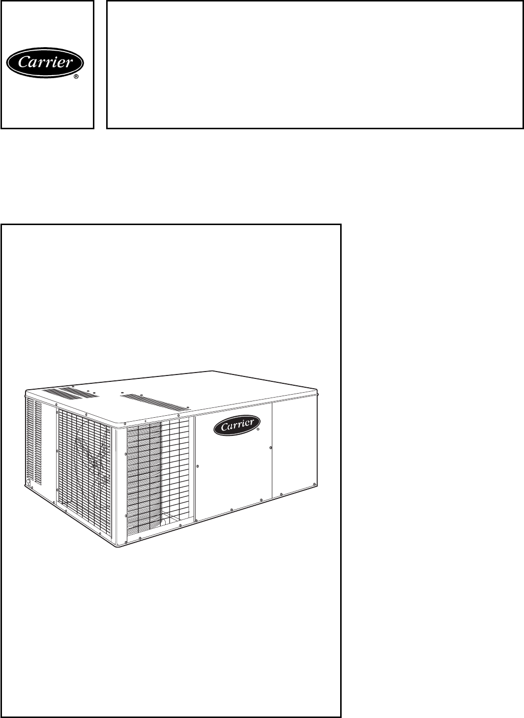
Single-Package Rooftop Products
with Energy-Saving Features
• direct spark ignition
• low sound levels
• 81% AFUE on most units
• 10 SEER
Features/Benefits
One-piece heating and
cooling units with low
installation costs, depend-
able performance, and easy
maintenance
Easy installation
Factory-assembled package is a
compact, fully self-contained, combina-
tion gas heating/electric cooling unit
that is prewired, prepiped, and
precharged for minimum installation
expense.
These 48SS units are available in a
variety of standard and optional
heating/cooling size combinations
with voltage options to meet residen-
tial and light commercial require-
ments. Units are lightweight and install
easily on a rooftop or a ground-level
pad.
Convertible duct
configuration
Unit is designed for easy use in either
downflow or horizontal applications.
Efficient operation
High-efficiency design with SEERs
(Seasonal Energy Efficiency Ratios)
of 10.0 and AFUE (Annual Fuel Utili-
zation Efficiency) ratings as high as
81.0%. All units have a minimum
CSE (California Seasonal Efficiency)
rating of 76.5%.
Product
Data
48SS
Single-Package
Gas Heating/Electric Cooling
Units
1
1
⁄
2
to 5 Nominal Tons
Copyright 1998 Carrier Corporation Form 48SS-4PD

Energy-saving, direct-spark igni-
tion saves gas by operating only
when the room thermostat calls for
heating. Standard units are furnished
with natural gas controls. A low-
cost, field-installed kit for propane
conversion is available for all units.
Monoport inshot burners produce
precise air-to-gas mixture which
provides for clean and efficient com-
bustion. The large monoport on
the inshot (or injection type) burners
seldom, if ever, needs cleaning. All
gas furnace components are accessible
in one compartment.
The 48SS units meet California
Air Quality Management NO
x
requirement of 40 nanograms/
joule or less when NO
x
kit
no. CRLOWNOX001A00 is
installed.
Durable, dependable
components
Top quality, top reliability compo-
nents are designed and tested for a
minimum of 15 years of operation
under the harshest conditions. Every
48SS unit is thoroughly run-tested
at the factory in each operating mode,
and is evacuated prior to final
charging.
Compressors are designed for high
efficiency. Each compressor is her-
metically sealed against contamination
to help promote longer life and de-
pendable operation. Each compressor
also has vibration isolation to pro-
vide quiet operation. All compressors
have internal high-pressure and
overcurrent protection. Rotary com-
pressors are standard on unit
size 018. Reciprocating compressors
are standard on unit sizes 024-042.
Scroll compressors are standard on
unit sizes 048 and 060.
Dimpled heat exchangers optimize
heat transfer for improved efficiency.
The tubular design permits hot gases
to stay in close contact with the cell
walls to maximize heat transfer and
efficiency.
The induced draft combustion
system eliminates the unsightly ap-
pearance of flue stacks, and diminishes
the effects of wind on heating opera-
tion. The induced draft also pre-
vents contaminants from entering the
supply air if a leak in the heat ex-
changer occurs.
Direct-drive multispeed, PSC
(permanent split capacitor)
blower motor is standard on all
models.
Direct-drive, PSC condenser-fan
motor is designed to help reduce
energy consumption and provide for
cooling operation down to 40 F
outdoor temperature.
Refrigerant system is designed to
provide dependability. Liquid refriger-
ant strainers are used to promote
clean, unrestricted operation. Each
unit leaves the factory with a full refrig-
erant charge. Refrigerant service
connections make checking operating
pressures easier.
Color-coded wires permit easy trac-
ing and diagnostics.
Evaporator and condenser coils
are computer-designed for optimum
heat transfer and cooling efficiency.
Condenser coil is fabricated of copper
tube and aluminum fins and is lo-
cated inside the unit for protection
against damage for long life and reli-
able operation. The condenser coil
is internally mounted and protected by
a composite grille. Copper fin coils
are also available from the factory by
special order. These coils are rec-
ommended in applications where alu-
minum fins are likely to be damaged
due to corrosion and are ideal for sea-
coast applications.
Low sound ratings ensure a quiet
indoor and outdoor environment with
sound ratings as low as 7.4 bels.
Easy to service cabinets provide
easy accessibility to serviceable com-
ponents during maintenance and
installation. Rounded corners are an
important safety feature, and a high
quality finish ensures an attractive
appearance.
Optional base rails provide holes
for rigging and forklifts as well as
an elevated mounting frame that pro-
vides structural support for horizon-
tal installations. Ideal for light
commercial applications.
Downflow option unit is converted
for downflow at the factory to al-
low vertical ductwork connections.
Unit is equipped with base rail.
Low and high voltage electrical
entries allow low and high voltage to
be brought in through either the
front duct panel or rear flue panel.
Integrated gas unit controller
(IGC) contains all the ignition compo-
nents and is easily accessible for ser-
vice. The IGC provides built-in
diagnostic capabilities. A light-emitting
diode (LED) simplifies troubleshoot-
ing by providing visual fault notifi-
cation and system status information.
The IGC board provides exclusive
anti-cycle protection for gas heat
operation. The IGC also contains
burner control logic for dependable
heating operation. The 48SS units
maximize heating efficiency through
the IGC’s control of evaporator fan
ON/OFF delays. The IGC helps make
48SS units reliable for years.
Weatherized cabinets are con-
structed of heavy-duty, phosphated,
zinc-coated prepainted steel capable
of withstanding 500 hours (Federal
Test Method Standard No. 141,
Method 6061) in salt spray. Interior
surfaces of the evaporator/heat
exchanger compartment are insulated
with cleanable, foil-faced insulation
for improved indoor-air quality. Unit
conforms to American Society of
Heating, Refrigeration and Air Condi-
tioning Engineers [ASHRAE]
No. 62, with use of a sloped conden-
sate pan. An external drain trap is
required.
The standard control system is
readily adaptable to all conventional
and programmable thermostats. In
addition, units are suitable for integra-
tion into monitor control systems if
required.
Standardized components for the
complete 48SS line of products are
found in all safety devices, condenser-
fan motors, evaporator-fan motors,
and control boards, while the gas sec-
tions use common inducer motors,
limit switches, and rollout switches.
This allows for greater inventory con-
trol, familiarity of parts, and fewer
stocked parts.
2
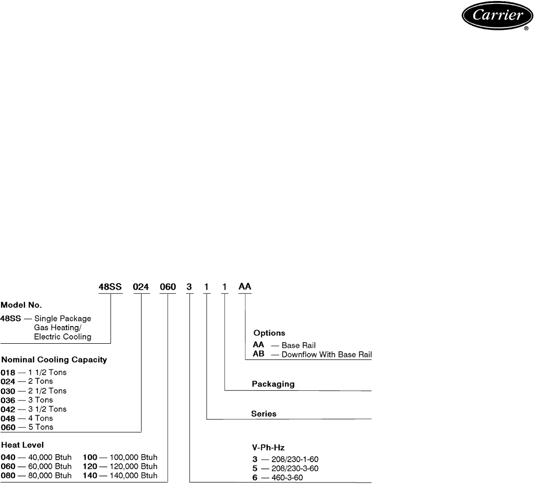
Table of contents
Page
Features/Benefits ..................................................1,2
Model Number Nomenclature ........................................3
ARI Capacities ....................................................4,5
Physical Data ......................................................6
Options and Accessories .............................................7
Base Unit Dimensions .............................................8-11
Accessory Dimensions ...........................................12,13
Selection Procedure ................................................13
Performance Data ...............................................14-18
Typical Installation .................................................19
Application Data ..................................................20
Typical Control Wiring Schematic ..................................21-23
Electrical Data ....................................................24
Controls ..........................................................25
Guide Specifications .............................................26,27
Model number nomenclature
3
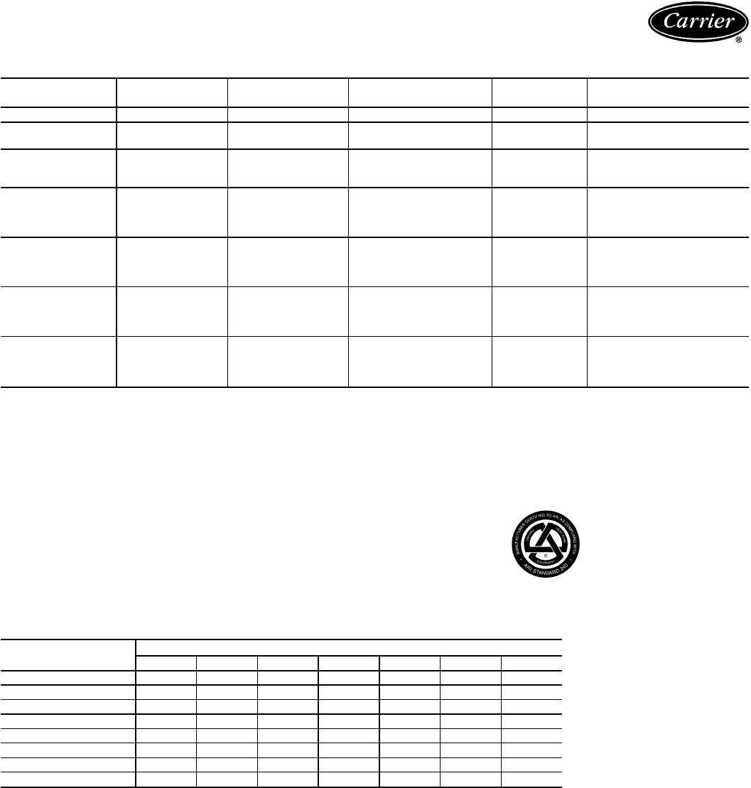
ARI* capacities
COOLING CAPACITIES AND EFFICIENCIES
UNIT 48SS NOMINAL
TONS STANDARD
CFM NET COOLING†
CAPACITIES SEER† SOUND RATINGS**
(Bels)
018040 1
1
⁄
2
600 17,000 10.0 7.4
024040
024060 2 800 24,000 10.0 7.6
030040
030060
030080 2
1
⁄
2
1000 29,200 10.0 8.0
036060
036080
036100
036120
3 1200 36,000 10.0 8.0
042060
042080
042100
042120
3
1
⁄
2
1400 42,500 10.0 8.2
048080
048100
048120
048140
4 1600 47,000 10.0 8.2
060080
060100
060120
060140
5 1995 59,500 10.0 8.2
LEGEND
Bels — Sound Levels (1 bel = 10 decibels)
db — Dry Bulb
SEER — Seasonal Energy Efficiency Ratio
wb — Wet Bulb
*Air Conditioning & Refrigeration Institute.
†Rated in accordance with U.S. Government DOE (Department of
Energy) test procedures and/or ARI Standard 210/240.
**Rated in accordance with ARI Standard 270.
NOTES:
1. Capacity ratings are net values, reflecting the effects of circulating
fan heat.
Ratings are based on:
Cooling Standard: 80 F db, 67 F wb indoor entering-air tempera-
ture and 95 F db outdoor entering-air temperature.
2. Before purchasing this appliance, read important energy cost and ef-
ficiency information available from your retailer.
OUTDOOR SOUND: ONE-THIRD OCTAVE BAND DATA — DECIBELS
FREQUENCY (Hz) UNIT 48SS
018 024 030 036 042 048 060
63 49.8 38.1 45.7 47.8 45.5 56.0 54.3
125 56.5 55.0 58.1 59.3 61.2 65.6 65.1
250 60.3 65.3 68.7 67.4 70.4 71.5 71.5
500 59.8 67.2 64.7 68.8 69.9 71.4 72.7
1000 64.1 68.9 73.0 73.1 76.5 74.2 73.9
2000 64.1 65.5 70.2 69.5 71.3 73.3 73.4
4000 65.2 63.8 68.8 68.2 73.7 69.6 71.7
8000 56.0 60.3 66.6 65.8 65.5 67.1 66.3
Bels — Sound Levels (1 bel = 10 decibels)
4
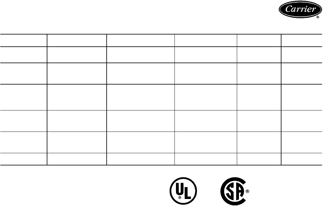
HEATING CAPACITIES AND EFFICIENCIES
UNIT 48SS HEATING INPUT
(Btuh) OUTPUT CAPACITY
(Btuh) TEMPERATURE
RISE RANGE (°F) AFUE (%) CSE (%)
018040
024040
030040 40,000 32,800 20-50
20-50
20-50
81
81
81
76.5
76.5
76.5
024060
030060
036060
042060
60,000 48,600
25-55
25-55
25-55
25-55
81
81
81
81
77.5
77.5
77.5
77.5
030080
036080
042080
048080
060080
80,000 64,800
40-70
40-70
40-70
40-70
40-70
81
81
81
81
81
77.5
77.5
77.5
77.5
77.5
036100
042100
048100
060100
100,000 81,000
50-80
50-80
50-80
50-80
81
81
81
81
78.0
78.0
78.0
78.0
036120
042120
048120
060120
120,000 97,200
60-90
60-90
60-90
60-90
80
80
80
80
77.5
77.5
77.5
77.5
048140
060140 140,000 113,000 50-80
50-80 80
80 77.5
77.5
LEGEND
AFUE — Annual Fuel Utilization Efficiency
CSE — California Seasonal Efficiency
NOTE: Before purchasing this appliance, read important energy cost
and efficiency information available from your retailer.
5
Physical data
UNIT SIZE 48SS 018040 024040 024060 030040 030060 030080 036060 036080 036100 036120
NOMINAL CAPACITY (ton) 1
1
⁄
2
222
1
⁄
2
2
1
⁄
2
2
1
⁄
2
3333
OPERATING WEIGHT (lb)
Without Base Rail 272 303 315 320 324 324 336 336 348 348
With Optional Base Rail 296 327 339 344 356 356 360 360 372 372
COMPRESSORS Rotary Reciprocating
Quantity 11
REFRIGERANT (R-22)
Charge (lb) 2.60 2.75 2.75 3.40 3.40 3.40 4.30 4.30 4.30 4.30
REFRIGERANT METERING DEVICE Acutrol™ Device
Orifice ID (in.) .030 .030 .030 .030 .030 .030 .032 .032 .032 .032
CONDENSER COIL
Rows...Fins/in. 1...17 1...17 1...17 2...17 2...17 2...17 2...17 2...17 2...17 2...17
Face Area (sq ft) 5.95 5.95 5.95 5.95 5.95 5.95 5.95 5.95 5.95 5.95
CONDENSER FAN
Nominal Cfm 1700 1700 1700 1900 1900 1900 1900 1900 1900 1900
Diameter (in.) 18 18 18 18 18 18 18 18 18 18
Motor Hp (Rpm)
1
⁄
8
(850)
1
⁄
8
(850)
1
⁄
8
(850)
1
⁄
8
(850)
1
⁄
8
(850)
1
⁄
8
(850)
1
⁄
4
(1050)
1
⁄
4
(1050)
1
⁄
4
(1050)
1
⁄
4
(1050)
EVAPORATOR COIL
Rows...Fins/in. 3...15 3...15 3...15 3...15 3...15 3...15 3...15 3...15 3...15 3...15
Face Area (sq ft) 1.83 2.29 2.29 2.29 2.29 2.29 3.06 3.06 3.06 3.06
EVAPORATOR FAN Direct Drive
Nominal Airflow (Cfm) 600 800 800 1000 1000 1000 1200 1200 1200 1200
Size (in.) 10x10 10x10 10x10 10x10 10x10 10x10 10x10 10x10 10x10 10x10
FURNACE SECTION*
Burner Orifice No. (Qty...drill size)
Natural Gas 1...32 1...32 2...40 1...32 2...40 2...32 2...40 2...32 2...30 3...32
Burner Orifice No. (Qty...drill size)
Propane Gas 1...41 1...41 2...47 1...41 2...47 2...42 2...47 2...42 2...40 3...42
RETURN-AIR FILTERS (in.)†
Throwaway 20x20 20x20 20x20 20x24 20x24 20x24 20x24 20x24 20x24 20x24
UNIT SIZE 48SS 042060 042080 042100 042120 048080 048100 048120 048140 060080 060100 060120 060140
NOMINAL CAPACITY (ton) 3
1
⁄
2
3
1
⁄
2
3
1
⁄
2
3
1
⁄
2
44445555
OPERATING WEIGHT (lb)
Without Base Rail 375 375 387 387 414 426 426 426 453 465 465 465
With Optional Base Rail 399 399 411 411 438 450 450 450 477 489 489 489
COMPRESSORS Reciprocating Hermetic Scroll
Quantity 11
REFRIGERANT (R-22)
Charge (lb) 5.20 5.20 5.20 5.20 6.50 6.50 6.50 6.50 7.00 7.00 7.00 7.00
REFRIGERANT METERING Acutrol™ Device
DEVICE
Orifice ID (in.) .034 .034 .034 .034 .030 .030 .030 .030 .030 .030 .030 .030
CONDENSER COIL
Rows...Fins/in. 2...17 2...17 2...17 2...17 2...17 2...17 2...17 2...17 2...17 2...17 2...17 2...17
Face Area (sq ft) 7.04 7.04 7.04 7.04 8.67 8.67 8.67 8.67 8.67 8.67 8.67 8.67
CONDENSER FAN
Nominal Cfm 1900 1900 1900 1900 2400 2400 2400 2400 2400 2400 2400 2400
Diameter (in.) 18 18 18 18 20 20 20 20 20 20 20 20
Motor Hp (Rpm)
1
⁄
4
(1050)
1
⁄
4
(1050)
1
⁄
4
(1050)
1
⁄
4
(1050)
1
⁄
3
(1050)
1
⁄
3
(1050)
1
⁄
3
(1050)
1
⁄
3
(1050)
1
⁄
3
(1050)
1
⁄
3
(1050)
1
⁄
3
(1050)
1
⁄
3
(1050)
EVAPORATOR COIL
Rows...Fins/in. 3...15 3...15 3...15 3...15 3...15 3...15 3...15 3...15 4...15 4...15 4...15 4...15
Face Area (sq ft) 3.33 3.33 3.33 3.33 4.44 4.44 4.44 4.44 4.44 4.44 4.44 4.44
EVAPORATOR FAN Direct Drive
Nominal Airflow (Cfm) 1400 1400 1400 1400 1600 1600 1600 1600 1995 1995 1995 1995
Size (in.) 10x10 10x10 10x10 10x10 10x10 10x10 10x10 10x10 10x10 10x10 10x10 10x10
FURNACE SECTION*
Burner Orifice No.
(Qty...drill size)
Natural Gas 2...40 2...32 2...30 3...32 2...32 2...30 3...32 3...31 2...32 2...30 3...32 3...31
Burner Orifice No.
(Qty...drill size)
Propane Gas 2...47 2...42 2...40 3...42 2...42 2...40 3...42 3...40 2...42 2...40 3...42 3...40
RETURN-AIR FILTERS (in.)†
Throwaway 24 x 24 24 x 24 24 x 24 24 x 24 24 x 30 24 x 30 24 x 30 816** 24 x 30 24 x 30 24 x 30 960**
*Based on altitude of 0-2000 feet.
†Required filter sizes shown are based on the larger of the ARI (Air Conditioning & Refrigeration Institute) rated
cooling airflow or the heating airflow at a velocity of 300 ft/min for throwaway type or 450 ft/min for high-capacity
type. Air filter pressure drop for non-standard filters must not exceed 0.08 in. wg.
**Sq inch. Filter is mounted external to unit.
6
Options and accessories
Factory-installed options
Unit with base rail provides holes for rigging and forklifts
as well as an elevated mounting frame that gives additional
structural support for horizontal installations. Ideal for light
commercial applications.
Downflow option unit is shipped from factory configured
for vertical ductwork connection. Unit is equipped with
base rail.
Field-installed accessories
Factory-assembled roof curbs are designed for use on
downflow discharge applications. Heavy gage, galvanized
steelconstruction provides one-piece support. Thecurb com-
plies with the standards of the NRCA (National Roofing
Contractors Association). A wood nailing strip is provided
for attaching the roofing to the curb.
25% Open manual outdoor-air damper provides for
minimum outdoor air and is manually adjustable.
Thermostat and subbase provide heating and cooling
unit control. The subbase provides system and fan switch-
ing at the thermostat location.
Carrier electronic programmable thermostats pro-
vide 2-stage heating and 2-stage cooling control with re-
mote communication ability.
Low-ambient kit (MotormastertII device) allows the
use of mechanical cooling down to outdoor ambient tem-
peratures as low as 0° F.
LP conversion kit allows for conversion from natural gas
to liquid propane. Conversion kit involves changing the gas
orifices and adding ceramic baffles to accommodate liquid
propane.
Solid-state Time GuardtII device protects compressor
by preventing short cycling.
Crankcase heater warms crankcase oil to reduce refrig-
erant migration and ensure proper compressor lubrication.
(Recommended on 208/230-v single-phase units in sizes
024-042 only).
High- and low-pressure switches provide additional
safety features and protect the unit from running at unsuit-
able pressures.
Filter rack featureseasy installation, serviceability, and high
filtering performance for vertical applications.
Lifting bracket kit provides attachment points for rigging
straps. The kit is not required when unit is equipped with
an optional base rail or downflow application.
High altitude kit is for use at 2001 to 5000 feet above
sea level. Kit consists of natural gas orifices that compen-
sate for gas heat operation at high altitude.
Low NO
x
kit provides compliance with low NO
x
emissions
requirements for units being installed in California Air Qual-
ity Management Districts, which require NO
x
emissions of
40 nanograms/joule or less.
UNIT WITH OPTIONAL BASE RAIL
7
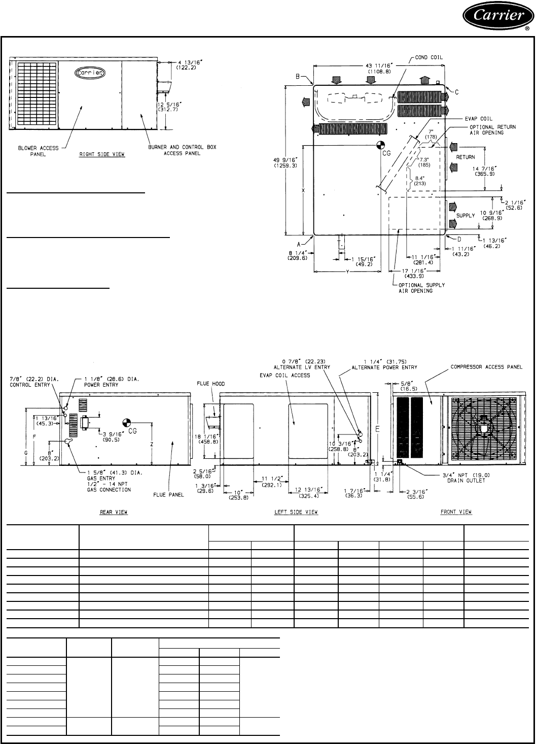
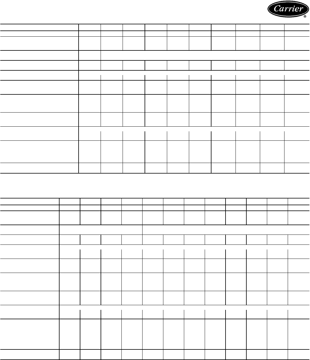
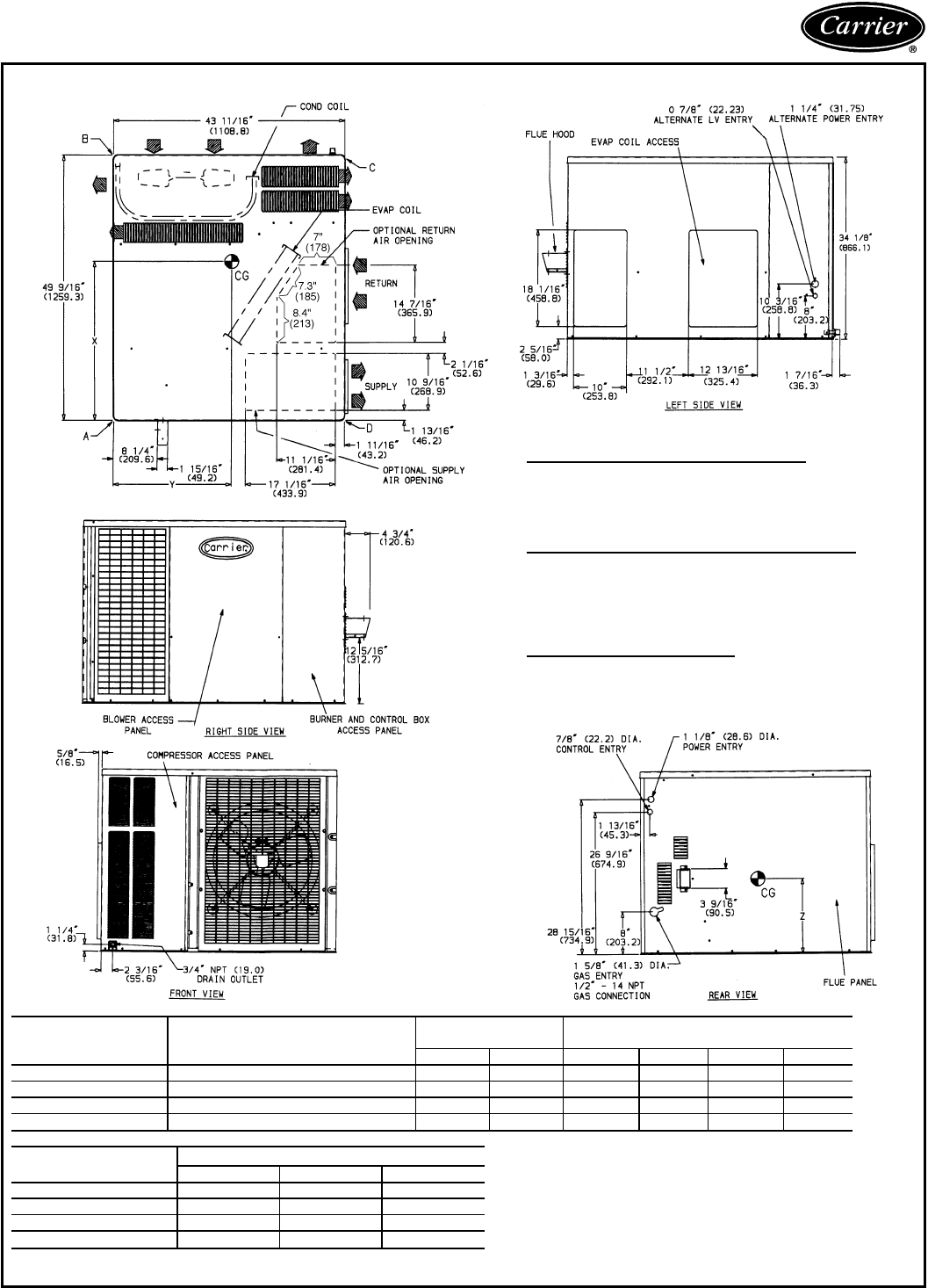
Base unit dimensions
REQ’D CLEARANCES FOR SERVICING. in. (mm)
Duct panel ........................0
Unit top .......................36(914)
Side opposite ducts ..................36(914)
Compressor access ..................36(914)
(Except for NEC requirements)
REQ’D CLEARANCES TO COMBUSTIBLE MAT’L. in. (mm)
Maximum extension of overhangs ............48(1219)
Unit top .......................14(356)
Duct side of unit ....................2(51)
Side opposite ducts ..................14(356)
Bottom of unit .......................0
Flue panel ......................36(914)
NEC REQ’D CLEARANCES. in. (mm)
Between units, control box side .............42(1067)
Unit and ungrounded surfaces, control box side .......36(914)
Unit and block or concrete walls and other grounded
surfaces, control box side ...............42(1067)
UNIT ELECTRICAL
CHARACTERISTICS UNIT WEIGHT CORNER WEIGHT
(lb/kg) UNIT HEIGHT
(in./mm)
lbkgABCD E
48SS180040 208/230-1-60 272 123 81/37 62/28 76/35 53/24 24.1/613
48SS024040 208/230-1-60 303 138 97/44 43/20 123/56 40/18 24.1/613
48SS024060 208/230-1-60 315 143 100/45 46/21 126/57 43/20 24.1/613
48SS030040 208/230-1-60, 208/230-3-60 320 145 100/45 47/21 126/57 47/21 24.1/613
48SS030060/080 208/230-1-60, 208/230-3-60 324 147 94/43 63/29 115/52 52/24 24.1/613
48SS036060/080 208/230-1-60, 208/230-3-60, 460-3-60 336 153 86/39 76/35 111/50 63/29 24.1/613
48SS036100/120 208/230-1-60, 208/230-3-60, 460-3-60 348 158 89/40 79/36 114/52 66/30 24.1/613
48SS042060/080 208/230-1-60, 208/230-3-60, 460-3-60 375 170 95/43 86/39 119/54 75/34 28.1/714
48SS042100/120 208/230-1-60, 208/230-3-60, 460-3-60 387 176 98/45 89/40 122/55 78/35 28.1/714
UNIT F
in./mm G
in./mm CENTER OF GRAVITY in./mm
XYZ
48SS018040
16
9
⁄
16
/420.7 18
15
⁄
16
/481.0
25.07/637 20.59/523
10.85/276
48SS024040 27.07/688 23.35/593
48SS024060 26.98/685 23.27/591
48SS030040 26.71/678 23.46/596
48SS030060/080 27.15/689 22.36/568
48SS036060/080 27.50/698 22.48/571
48SS036100/120 27.40/696 22.44/570
48SS042060/080 20
9
⁄
16
/522.3 22
15
⁄
16
/582.6 27.01/686 22.44/570 12.7/321
48SS042100/120 26.94/684 22.44/570
LEGEND
CG — Center of Gravity
COND — Condenser
LV — Low Voltage
MAT’L — Material
NEC — National Electrical Code
REQ’D — Required
NOTES:
1. Clearances must be maintained to prevent recirculation of air
from outdoor-fan discharge.
2. Adequate clearance around air openings into combustion cham-
ber must be provided.
48SS018-042 WITHOUT OPTIONAL BASE RAIL
8
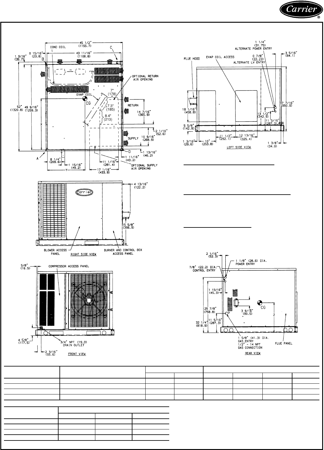
48SS018-042 WITH OPTIONAL BASE RAIL
REQ’D CLEARANCES FOR SERVICING. in. (mm)
Duct panel ........................0
Unit top ......................36(914)
Side opposite ducts .................36(914)
Compressor access .................36(914)
(Except for NEC requirements)
REQ’D CLEARANCES TO COMBUSTIBLE MAT’L. in. (mm)
Maximum extension of overhangs ...........48(1219)
Unit top ......................14(356)
Duct side of unit ....................2(51)
Side opposite ducts .................14(356)
Bottom of unit .......................0
Flue panel .....................36(914)
NEC REQ’D CLEARANCES. in. (mm)
Between units, control box side ............42(1067)
Unit and ungrounded surfaces, control box side ......36(914)
Unit and block or concrete walls and other grounded
surfaces, control box side ..............42(1067)
UNIT ELECTRICAL
CHARACTERISTICS UNIT WEIGHT CORNER WEIGHT
(lb/kg) UNIT HEIGHT
(in./mm)
lbkgABCD E
48SS018040 208/230-1-60 296 135 87/40 68/31 82/37 59/27 27.4/697
48SS024040 208/230-1-60 327 149 103/47 49/22 129/59 46/21 27.4/697
48SS024060 208/230-1-60 339 155 106/48 52/24 132/60 49/22 27.4/697
48SS030040 208/230-1-60, 208/230-3-60 344 157 106/48 53/24 132/60 53/24 27.4/697
48SS030060/080 208/230-1-60, 208/230-3-60 356 162 102/46 71/32 123/56 60/27 27.4/697
48SS036060/080 208/230-1-60, 208/230-3-60, 460-3-60 360 164 92/42 82/37 117/53 69/31 27.4/697
48SS036100/120 208/230-1-60, 208/230-3-60, 460-3-60 372 169 95/43 85/39 120/55 72/33 27.4/697
48SS042060/080 208/230-1-60, 208/230-3-60, 460-3-60 399 181 101/46 92/42 125/57 81/37 31.4/798
48SS042100/120 208/230-1-60, 208/230-3-60, 460-3-60 411 187 104/47 95/43 128/58 84/38 31.4/798
UNIT F
in./mm G
in./mm CENTER OF GRAVITY in./mm
XYZ
48SS018040
19
7
⁄
8
/504.8 22
1
⁄
4
/565.4
25.04/636 22.72/577
13.16/334.3
48SS024040 26.90/683.3 20.17/512.3
48SS024060 26.82/681.2 20.22/513.6
48SS030040 26.57/674.9 20.1/ 509.3
48SS030060/080 26.93/684 21.1/535.4
48SS036060/080 27.31/693.7 21.0/532.6
48SS036100/120 27.23/691.6 21.0/533.1
48SS042060/080 23
7
⁄
8
/606.4 26
1
⁄
4
/666.8 26.87/682.5 21.0/533.1 14.96/380
48SS042100/120 26.81/681 21.0/533.7
LEGEND
CG — Center of Gravity
COND — Condenser
LV — Low Voltage
MAT’L — Material
NEC — National Electrical Code
REQ’D — Required
NOTES:
1. Clearances must be maintained to prevent recirculation of air from
outdoor-fan discharge.
2. Adequate clearance around air openings into combustion chamber
must be provided.
9
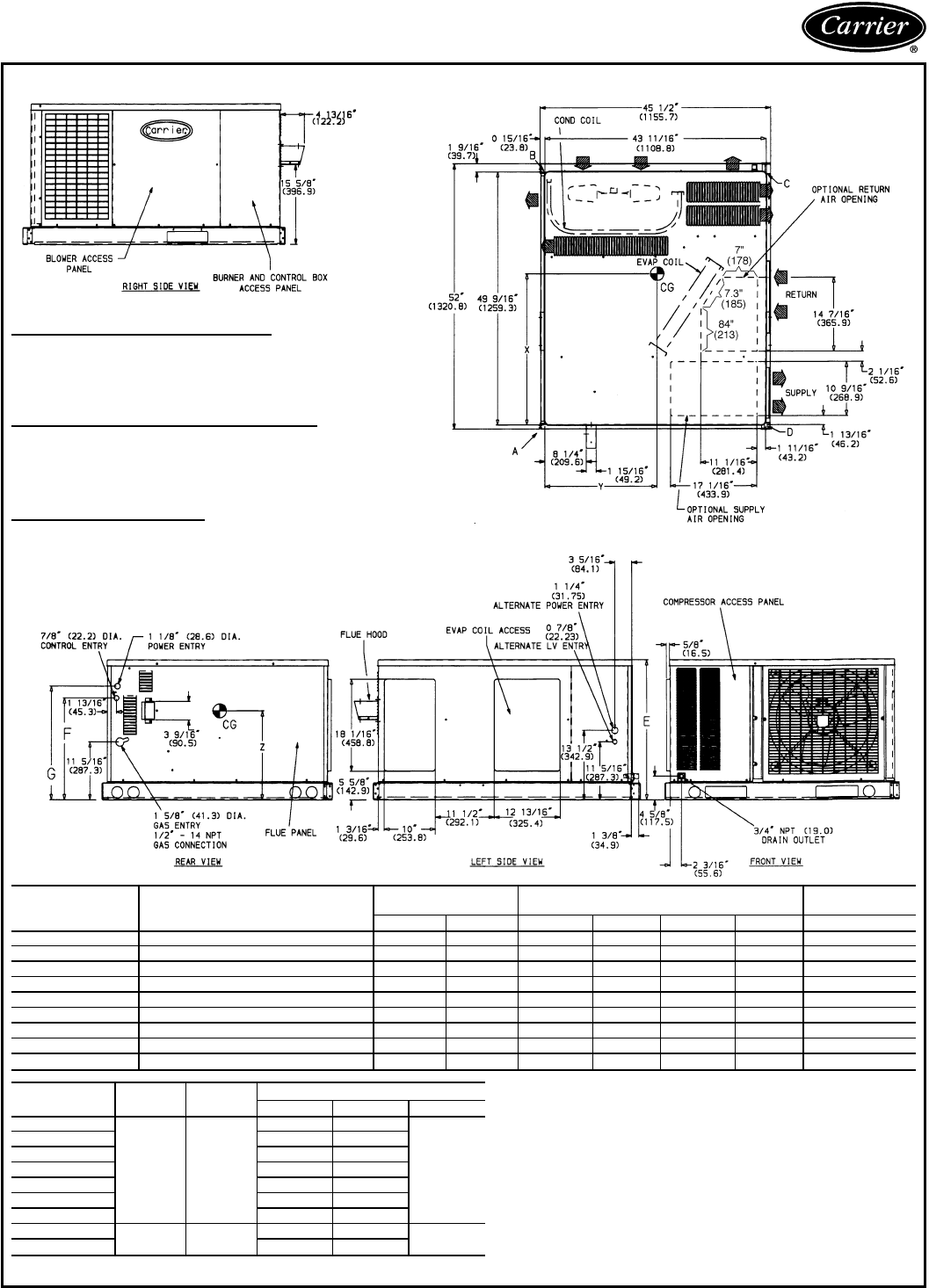
Base unit dimensions (cont)
48SS048,060 WITHOUT OPTIONAL BASE RAIL
REQ’D CLEARANCES FOR SERVICING. in. (mm)
Duct panel .......................0
Unit top ......................36(914)
Side opposite ducts ................36(914)
Compressor access ................36(914)
(Except for NEC requirements)
REQ’D CLEARANCES TO COMBUSTIBLE MAT’L. in. (mm)
Maximum extension of overhangs .........48(1219)
Unit top ......................14(356)
Duct side of unit ...................2(51)
Side opposite ducts ................14(356)
Bottom of unit ......................0
Flue panel ....................36(914)
NEC REQ’D CLEARANCES. in. (mm)
Between units, control box side ..........42(1067)
Unit and ungrounded surfaces, control box side ....36(914)
Unit and block or concrete walls and other grounded
surfaces, control box side .............42(1067)
UNIT ELECTRICAL
CHARACTERISTICS UNIT WEIGHT CORNER WEIGHT
(lb/kg)
lb kg A B C D
48SS048080 208/230-1-60, 208/230-3-60, 460-3-60 414 188 107/49 83/38 158/72 66/30
48SS048100/120/140 208/230-1-60, 208/230-3-60, 460-3-60 426 193 110/50 86/39 159/72 71/32
48SS060080 208/230-1-60, 208/230-3-60, 460-3-60 453 206 117/53 93/42 167/76 76/35
48SS060100/120/140 208/230-1-60, 208/230-3-60, 460-3-60 465 211 120/55 96/44 167/76 82/37
UNIT CENTER OF GRAVITY (in./mm)
XYZ
48SS048080 28.76/731 23.46/596 15.35/390
48SS048100/120/140 28.42/722 23.42/595 15.35/390
48SS060080 28.36/720 23.27/591 15.35/390
48SS060100/120/140 27.95/710 23.23/590 15.35/390
LEGEND
CG — Center of Gravity
COND — Condenser
LV — Low Voltage
MAT’L — Material
NEC — National Electrical Code
REQ’D — Required
NOTES:
1. Clearances must be maintained to prevent recirculation of air from
outdoor-fan discharge.
2. Adequate clearance around air openings into combustion chamber must
be provided.
10
48SS048,060 WITH OPTIONAL BASE RAIL
REQ’D CLEARANCES FOR SERVICING. in. (mm)
Duct panel ........................0
Unit top ......................36(914)
Side opposite ducts .................36(914)
Compressor access .................36(914)
(Except for NEC requirements)
REQ’D CLEARANCES TO COMBUSTIBLE MAT’L. in. (mm)
Maximum extension of overhangs ...........48(1219)
Unit top ......................14(356)
Duct side of unit ....................2(51)
Side opposite ducts .................14(356)
Bottom of unit .......................0
Flue panel .....................36(914)
NEC REQ’D CLEARANCES. in. (mm)
Between units, control box side ............42(1067)
Unit and ungrounded surfaces, control box side ......36(914)
Unit and block or concrete walls and other grounded
surfaces, control box side ..............42(1067)
UNIT ELECTRICAL
CHARACTERISTICS UNIT WEIGHT CORNER WEIGHT (lb/kg)
lb kg A B C D
48SS048080 208/230-1-60, 208/230-3-60, 460-3-60 438 199 113/51 89/40 164/75 72/33
48SS048100/120/140 208/230-1-60, 208/230-3-60, 460-3-60 450 205 116/53 92/42 165/75 77/35
48SS060080 208/230-1-60, 208/230-3-60, 460-3-60 477 217 123/56 99/45 173/79 82/37
48SS060100/120/140 208/230-1-60, 208/230-3-60, 460-3-60 489 222 126/57 102/46 173/79 88/40
UNIT CENTER OF GRAVITY (in./mm)
XYZ
48SS048080 28.54/724.9 20.00/508 17.66/448.6
48SS048100/120/140 28.22/716.8 20.05/509.3 17.66/448.6
48SS060080 28.18/715.6 20.19/512.8 17.66/448.6
48SS060100/120/140 27.79/705.9 20.23/513.8 17.66/448.6
LEGEND
CG — Center of Gravity
COND — Condenser
LV — Low Voltage
MAT’L — Material
NEC — National Electrical Code
REQ’D — Required
NOTES:
1. Clearances must be maintained to prevent recirculation of air from
outdoor-fan discharge.
2. Adequate clearance around air openings into combustion chamber
must be provided.
11
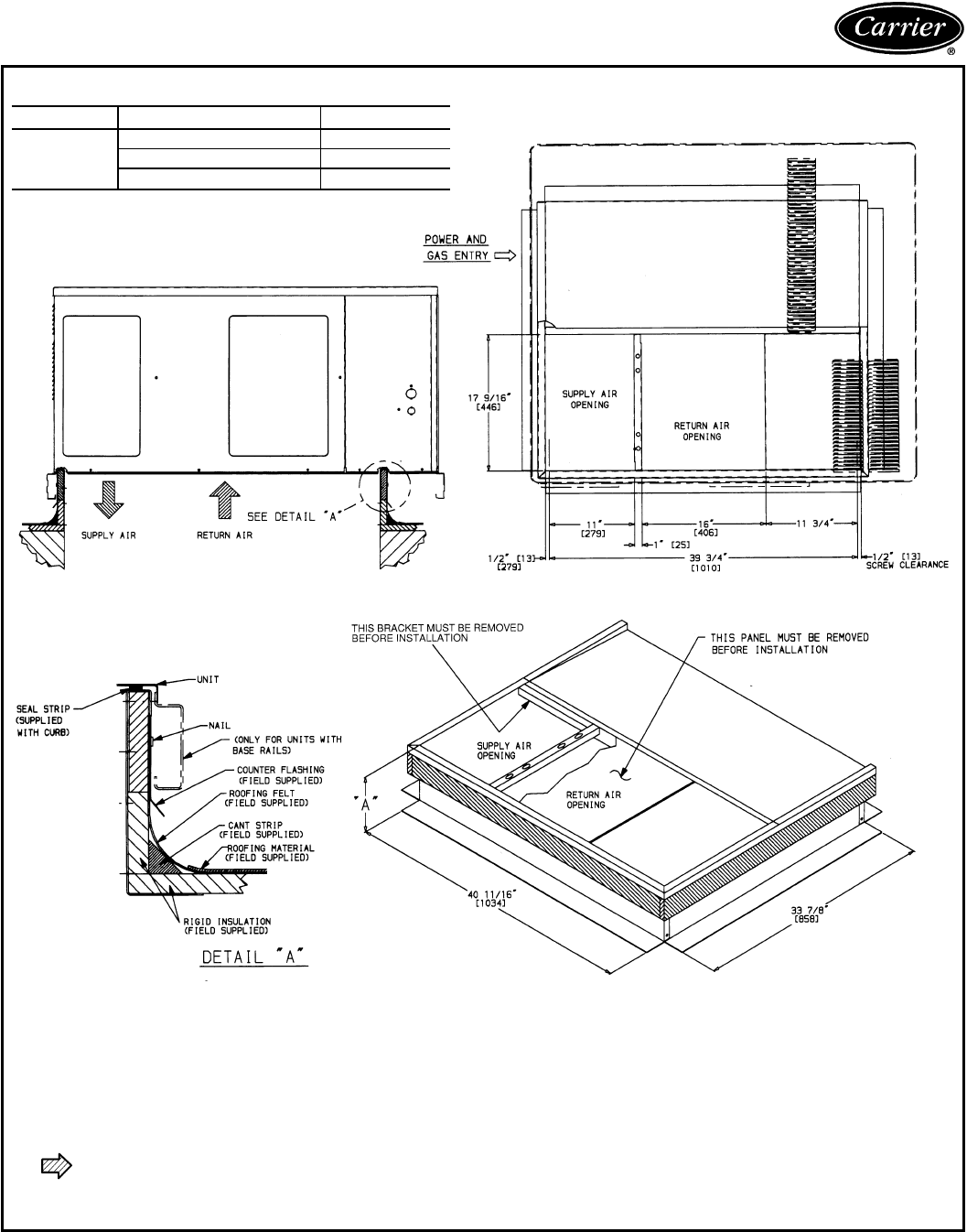
Accessory dimensions
ROOF CURB DIMENSIONS
PART NUMBER ‘‘A’’
48SS
CPRFCURB001A00 89[203]
CPRFCURB002A00 119[279]
CPRFCURB003A00 149[356]
NOTES:
1. Roof curb must be set up for unit being installed.
2. Seal strip must be applied as required for unit being installed.
3. Dimensions in [ ] are in millimeters.
4. Roof curb is made of 16 gage steel.
5. Attach ductwork to curb (flanges of duct rest on curb).
6. Service clearance 4 ft on each side.
7. Direction of airflow.
8. Insulated panels: 1-in. thick fiberglass 1 lb density.
12
Selection procedure (with example)
I Determine cooling and heating requirements at
design conditions:
Given:
Required Cooling Capacity (TC) ......34,000 Btuh
Sensible Heat Capacity (SHC) .......24,000 Btuh
Required Heating Capacity ..........60,000 Btuh
Condenser Entering-Air Temperature ........95F
Indoor-Air Temperature .......80Fedb, 67 F ewb
Evaporator-Air Quantity ...............1200 cfm
External Static Pressure ...............0.2in.wg
Electrical Characteristics (V-Ph-Hz) .......208-1-60
II Select unit based on required cooling capacity.
Enter Cooling Capacities table at condenser entering
temperature of 95 F. Unit 48SS036 at 1200 cfm and
67 F ewb (entering wet bulb) will provide a total ca-
pacity of 36,000 Btuh and an SHC of 26,200 Btuh.
Calculate SHC correction, if required, using Note 4
under Cooling Capacities tables.
III Select heating capacity of unit to provide design
condition requirement.
In the Heating Capacities and Efficiencies table on
page 5, note that unit 48SS036080 will provide
64,800 Btuh with an input of 80,000 Btuh.
IV Determine fan speed and power requirements
at design conditions.
Before entering the air delivery tables, calculate the
total static pressure required. From the given, the Wet
Coil Pressure Drop table, and the Filter Pressure Drop
table on page 18, find at 1200 cfm:
External static pressure 0.20 in. wg
Wet coil 0.088 in. wg
Filter 0.13 in. wg
Total static pressure 0.42 in. wg (rounded)
Enter the table for Dry Coil Air Delivery — Horizontal
Discharge for 230 and 460 V on page 16. For 208 v
operation, deduct 10% from value given. The fan will
deliver 1233 cfm at 0.4 external static pressure (1370
x 0.9) at high speed and 852 cfm at 0.5 external static
pressure(946 x0.9) atlow speed. The fan speed should
be set at high to satisfy job requirements.
V Select unit that corresponds to power source
available.
The Electrical Data table on page 24 shows that the
unit is designed to operate at 208-1-60.
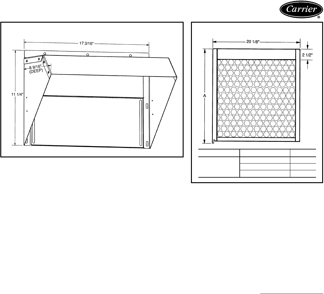
MANUAL OUTDOOR AIR DAMPER FILTER RACKS AND FILTERS
ACCESSORY PART NUMBER ‘‘A’’
FILTER
RACK
CPFILTRK001A00 21
11
⁄
16
9
CPFILTRK002A00 31
11
⁄
16
9
CPFILTRK003A00 25
11
⁄
16
9
13
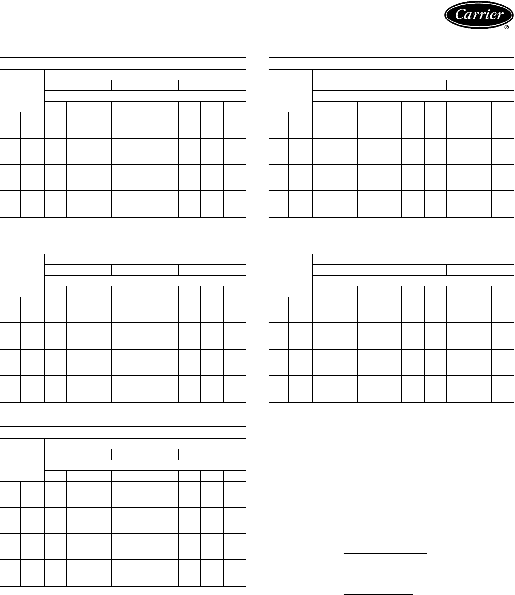
Performance data
COOLING CAPACITIES
48SS018
TEMP (F)
AIR ENT
COND
EVAP AIR — CFM/BF
525/0.10 600/0.12 675/0.13
Evap Air — Ewb (F)
62 67 72 62 67 72 62 67 72
85 TC 15.8 17.4 19.0 16.0 17.6 19.2 16.1 17.8 19.3
SHC 13.6 11.2 8.7 14.4 11.8 9.0 15.1 12.4 9.2
kW 1.76 1.80 1.85 1.81 1.86 1.90 1.86 1.91 1.95
95 TC 15.3 16.9 18.5 15.5 17.0 18.7 15.6 17.1 18.8
SHC 13.4 11.1 8.6 14.2 11.6 8.9 14.9 12.2 9.1
kW 1.90 1.95 2.00 1.95 2.00 2.05 2.01 2.05 2.10
105 TC 14.6 16.2 17.9 14.9 16.3 18.0 14.9 16.4 18.0
SHC 13.2 10.9 8.4 14.0 11.4 8.6 14.6 12.0 8.8
kW 2.05 2.10 2.15 2.10 2.15 2.20 2.15 2.20 2.25
115 TC 13.8 15.5 17.1 14.1 15.6 17.3 14.3 15.7 17.4
SHC 12.8 10.6 8.1 13.6 11.2 8.4 14.2 11.7 8.7
kW 2.20 2.26 2.31 2.25 2.31 2.37 2.31 2.36 2.42
48SS024
TEMP (F)
AIR ENT
COND
EVAP AIR — CFM/BF
700/0.06 800/0.07 900/0.08
Evap Air — Ewb (F)
62 67 72 62 67 72 62 67 72
85 TC 22.5 25.1 27.8 23.0 25.6 28.3 23.4 26.0 28.7
SHC 19.8 16.6 13.2 21.2 17.6 13.7 22.3 18.6 14.2
kW 2.51 2.60 2.69 2.56 2.65 2.75 2.62 2.71 2.80
95 TC 21.1 23.6 26.3 21.5 24.0 26.6 21.9 24.4 27.0
SHC 19.3 16.1 12.7 20.5 17.1 13.1 21.5 18.1 13.7
kW 2.63 2.73 2.84 2.69 2.82 2.89 2.75 2.85 2.95
105 TC 19.6 22.0 24.6 20.0 22.4 25.0 20.5 22.6 25.3
SHC 18.5 15.5 12.1 19.7 16.5 12.7 20.5 17.4 13.2
kW 2.74 2.86 2.97 2.81 2.92 3.03 2.88 2.97 3.09
115 TC 17.9 20.3 22.9 18.6 20.6 23.2 19.2 20.9 23.5
SHC 17.6 14.9 11.6 18.5 15.9 12.2 19.2 16.9 12.7
kW 2.85 2.97 3.10 2.93 3.03 3.16 3.01 3.09 3.21
48SS030
TEMP (F)
AIR ENT
COND
EVAP AIR — CFM/BF
875/0.08 1000/0.09 1125/0.10
Evap Air — Ewb (F)
62 67 72 62 67 72 62 67 72
85 TC 27.5 30.7 33.7 28.0 31.1 34.0 28.4 31.3 34.5
SHC 25.2 21.0 16.3 26.8 22.3 16.9 28.2 23.4 17.6
kW 3.01 3.09 3.16 3.07 3.15 3.22 3.13 3.20 3.28
95 TC 25.8 28.8 31.7 26.3 29.2 32.3 26.9 29.4 32.4
SHC 24.4 20.4 15.6 25.9 21.6 16.4 26.9 22.7 16.9
kW 3.16 3.25 3.33 3.23 3.32 3.40 3.30 3.37 3.44
105 TC 23.9 26.9 29.9 24.6 27.2 30.1 25.3 27.5 30.5
SHC 23.4 19.6 15.0 24.6 20.9 15.6 25.3 22.1 16.4
kW 3.30 3.40 3.49 3.38 3.46 3.54 3.45 3.52 3.61
115 TC 21.9 24.8 27.6 22.9 25.0 28.0 23.6 25.2 28.1
SHC 21.9 18.8 14.2 22.9 20.1 15.0 23.6 21.2 15.6
kW 3.44 3.53 3.62 3.52 3.59 3.89 3.59 3.64 3.74
48SS036
TEMP (F)
AIR ENT
COND
EVAP AIR — CFM/BF
1050/0.07 1200/0.08 1350/0.09
Evap Air — Ewb (F)
62 67 72 62 67 72 62 67 72
85 TC 33.6 37.6 41.7 34.2 38.3 42.3 34.8 38.7 42.6
SHC 30.5 25.4 19.9 32.5 27.1 20.7 34.2 28.5 21.4
kW 3.72 3.86 3.99 3.81 3.95 4.08 3.90 4.03 4.15
95 TC 31.2 35.5 39.3 31.9 36.0 40.2 32.8 36.4 40.4
SHC 29.4 24.7 19.1 31.4 26.2 20.1 32.8 27.7 20.8
kW 3.90 4.05 4.18 3.99 4.14 4.29 4.09 4.22 4.36
105 TC 28.8 33.2 37.2 30.0 33.7 37.6 31.1 34.0 37.9
SHC 28.2 23.8 18.4 30.0 25.4 19.2 31.0 26.8 20.0
kW 4.08 4.23 4.39 4.17 4.32 4.48 4.29 4.41 4.56
115 TC 26.7 30.9 34.7 28.1 31.3 35.0 29.2 31.6 35.2
SHC 26.7 22.9 17.5 28.1 24.5 18.3 29.2 25.9 19.0
kW 4.26 4.41 4.57 4.37 4.50 4.66 4.48 4.58 4.73
48SS042
TEMP (F)
AIR ENT
COND
EVAP AIR — CFM/BF
1225/0.11 1400/0.12 1575/0.14
Evap Air — Ewb (F)
62 67 72 62 67 72 62 67 72
85 TC 40.3 44.2 47.9 41.1 44.9 48.5 41.8 45.4 49.0
SHC 36.1 30.0 23.5 38.3 31.7 24.3 40.2 33.2 25.0
kW 4.28 4.43 4.57 4.38 4.52 4.66 4.48 4.61 4.75
95 TC 38.0 41.8 45.3 38.8 42.5 45.9 39.4 43.0 46.4
SHC 34.9 29.2 22.5 37.1 30.9 23.4 38.9 32.5 24.2
kW 4.50 4.67 4.81 4.61 4.77 4.91 4.71 4.87 5.00
105 TC 35.7 39.3 43.0 36.4 39.9 43.3 37.2 40.4 43.7
SHC 33.8 28.2 21.8 35.8 29.9 22.5 37.2 31.5 23.4
kW 4.73 4.90 5.08 4.84 5.01 5.17 4.94 5.10 5.26
115 TC 33.3 36.7 40.1 34.1 37.2 40.4 35.0 37.6 40.8
SHC 32.5 27.2 20.7 34.1 28.8 21.4 35.0 30.4 22.3
kW 4.94 5.12 5.30 5.06 5.23 5.39 5.18 5.32 5.49
LEGEND
BF — Bypass Factor
edb — Entering Dry-Bulb
Ewb — Entering Wet-Bulb
kW — Total Unit Power Input
ldb — Leaving Dry-Bulb
lwb — Leaving Wet-Bulb
SHC — Sensible Heat Capacity, 1000 Btuh
TC — Total Cooling Capacity, 1000 Btuh (net)
NOTES:
1. Ratings are net; they account for the effects of the indoor-fan motor
power and heat.
2. Direct interpolation is permissible. Do not extrapolate.
3. The following formulas may be used:
sensible capacity (Btuh)
t=t –
ldb edb 1.10 x cfm
t = Wet-bulb temperature corresponding to enthalpy of air
lwb leaving indoor coil (h )
lwb
total capacity (Btuh)
h=h –
lwb ewb 4.5 x cfm
Where: h = Enthalpy of air entering indoor coil
ewb
4. The SHC is based on 80 F edb temperature of air entering indoor
coil.
Below 80 F edb, subtract (corr factor x cfm) from SHC.
Above 80 F edb, add (corr factor x cfm) to SHC.
Correction Factor = 1.10 x (1 – BF) x (edb – 80).
14
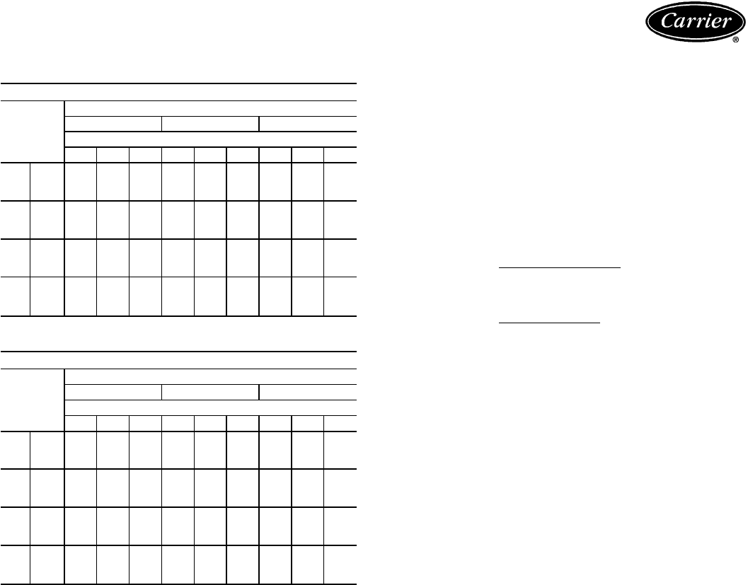
COOLING CAPACITIES (cont)
48SS048
TEMP (F)
AIR ENT
COND
EVAP AIR — CFM/BF
1400/0.08 1600/0.10 1800/0.11
Evap Air — Ewb (F)
62 67 72 62 67 72 62 67 72
85 TC 43.8 48.3 52.9 44.5 49.1 53.7 45.1 49.6 53.9
SHC 39.4 32.7 25.6 41.9 34.6 26.4 44.1 36.4 27.1
kW 4.76 4.85 4.95 4.87 4.97 5.07 4.99 5.08 5.17
95 TC 41.9 46.4 50.9 42.6 47.0 51.7 43.3 47.5 52.2
SHC 38.6 32.1 24.8 41.1 33.9 25.9 43.1 35.9 26.8
kW 5.17 5.28 5.38 5.29 5.40 5.50 5.41 5.51 5.61
105 TC 39.3 44.2 48.8 40.1 44.7 49.2 41.2 45.2 49.6
SHC 37.3 31.2 24.1 39.7 33.1 25.1 41.2 35.1 26.0
kW 5.61 5.73 5.83 5.74 5.85 5.95 5.87 5.96 6.06
115 TC 36.6 41.5 46.4 37.7 42.4 47.0 39.0 42.8 47.4
SHC 35.9 30.2 23.4 37.6 32.4 24.3 39.0 34.2 25.4
kW 6.08 6.22 6.34 6.22 6.34 6.45 6.36 6.46 6.57
48SS060
TEMP (F)
AIR ENT
COND
EVAP AIR — CFM/BF
1750/0.03 2000/0.04 2250/0.05
Evap Air — Ewb (F)
62 67 72 62 67 72 62 67 72
85 TC 55.0 62.0 69.4 56.3 63.1 70.5 58.2 63.9 71.3
SHC 52.4 43.7 34.2 56.1 46.7 35.8 58.1 49.5 37.4
kW 6.14 6.33 6.53 6.32 6.50 6.70 6.52 6.67 6.88
95 TC 51.8 58.8 66.2 53.6 59.6 67.3 55.6 60.2 68.1
SHC 51.0 42.4 33.2 53.5 45.3 34.8 55.6 48.2 36.3
kW 6.62 6.82 7.05 6.83 7.00 7.22 7.03 7.17 7.39
105 TC 48.7 55.1 62.9 51.0 56.0 63.9 53.0 56.7 64.5
SHC 48.7 41.1 32.1 50.9 44.0 33.7 52.8 46.9 35.3
kW 7.17 7.37 7.60 7.39 7.54 7.78 7.59 7.71 7.95
115 TC 45.8 52.0 59.5 48.5 52.8 60.5 50.4 53.4 60.8
SHC 45.8 40.0 30.9 48.4 42.8 32.6 50.3 45.6 34.1
kW 7.77 7.94 8.19 7.98 8.12 8.36 8.18 8.29 8.43
LEGEND
BF — Bypass Factor
edb — Entering Dry-Bulb
Ewb — Entering Wet-Bulb
kW — Total Unit Power Input
ldb — Leaving Dry-Bulb
lwb — Leaving Wet-Bulb
SHC — Sensible Heat Capacity, 1000 Btuh
TC — Total Cooling Capacity, 1000 Btuh (net)
NOTES:
1. Ratings are net; they account for the effects of the indoor-fan motor
power and heat.
2. Direct interpolation is permissible. Do not extrapolate.
3. The following formulas may be used:
sensible capacity (Btuh)
t=t –
ldb edb 1.10 x cfm
t = Wet-bulb temperature corresponding to enthalpy of air
lwb leaving indoor coil (h )
lwb
total capacity (Btuh)
h=h –
lwb ewb 4.5 x cfm
Where: h = Enthalpy of air entering indoor coil
ewb
4. The SHC is based on 80 F edb temperature of air entering indoor
coil.
Below 80 F edb, subtract (corr factor x cfm) from SHC.
Above 80 F edb, add (corr factor x cfm) to SHC.
Correction Factor = 1.10 x (1 – BF) x (edb – 80).
15
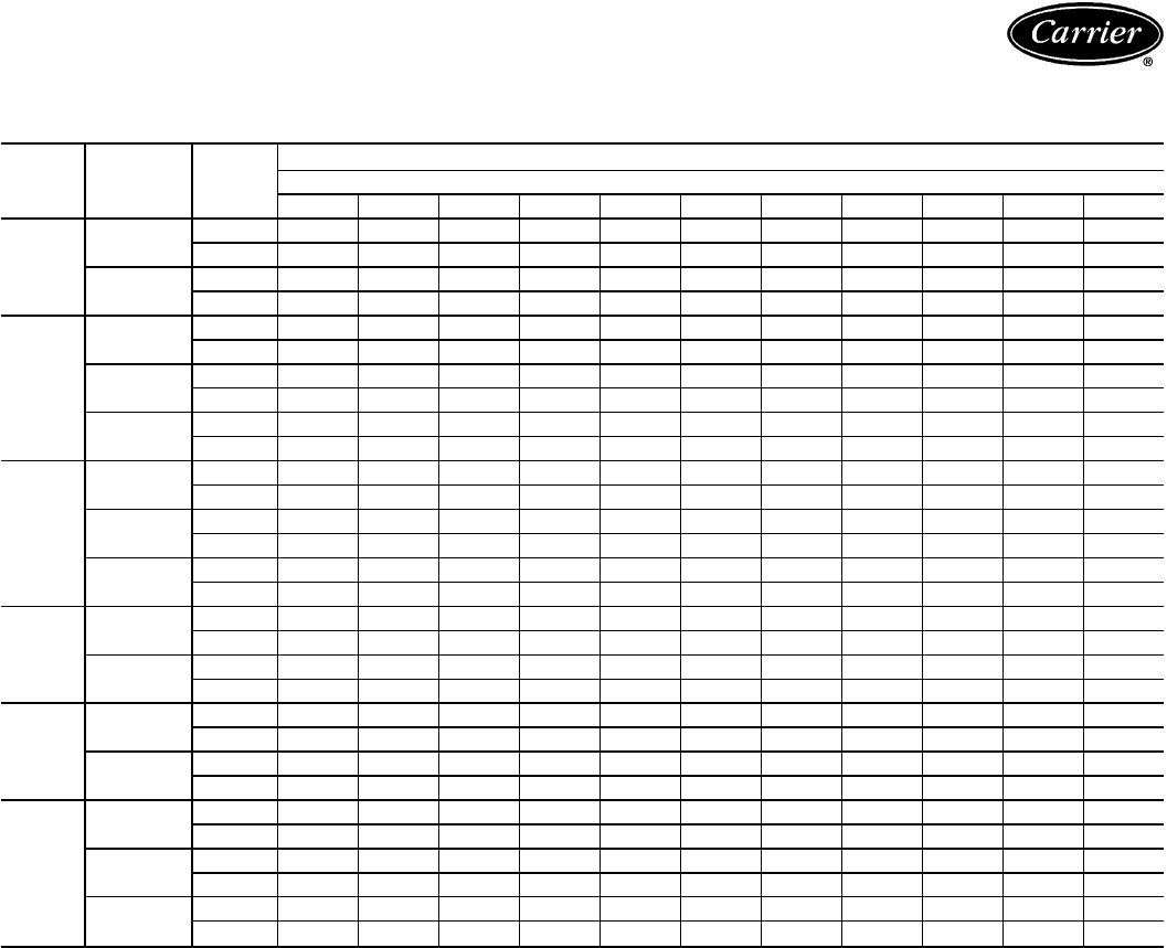
Performance data (cont)
DRY COIL AIR DELIVERY* — HORIZONTAL DISCHARGE
(Deduct 10% for 208 v)
UNIT
SIZE
48SS
MOTOR
SPEED
230 AND 460 VOLT HORIZONTAL DISCHARGE
External Static Pressure (in. wg)
0.0 0.1 0.2 0.3 0.4 0.5 0.6 0.7 0.8 0.9 1.0
018
Low Watts 230 225 220 210 195 170 —————
Cfm760745725695640540—————
High Watts ————270235200————
Cfm————850700450————
024,
030
Low Watts 275 275 273 269 260 257 249 ————
Cfm857835802782745717663————
Med Watts 371 368 360 349 345 326 319 304 293 — —
Cfm 1079 1063 1027 996 978 919 865 783 726 — —
High Watts 514 493 476 460 443 425 401 378 344 — —
Cfm 1409 1383 1324 1282 1223 1156 1068 984 857 — —
036
Low Watts 473 447 427 418 395 367 346 337 323 — —
Cfm 1253 1253 1172 1130 1047 946 865 829 768 — —
Med Watts 519 500 478 459 439 410 377 357 340 — —
Cfm 1414 1366 1287 1234 1162 1074 920 829 743 — —
High Watts 667 634 609 593 564 541 506 469 436 422 —
Cfm 1734 1639 1563 1461 1370 1292 1157 960 829 743 —
042
Low Watts 678 635 604 580 550 520 493 455 430 — —
Cfm 1540 1515 1475 1430 1375 1280 1225 1128 1020 — —
High Watts — 820 785 750 700 680 649 612 570 — —
Cfm — 1825 1750 1685 1610 1525 1485 1335 1215 — —
048
Low Watts — — 854 786 744 706 641 606 557 511 —
Cfm — — 2026 1905 1830 1752 1603 1513 1367 1228 —
High Watts — — — 905 846 824 804 748 683 637 —
Cfm — — — 2025 1905 1830 1752 1603 1398 1228 —
060
Low Watts 1104 1093 1072 1029 986 938 891 830 769 733 697
Cfm 1876 1865 1840 1803 1765 1710 1641 1533 1425 1345 1264
Med Watts 1351 1295 1245 1197 1148 1096 1053 994 936 871 812
Cfm 2249 2209 2157 2097 2036 1959 1882 1781 1679 1542 1405
High Watts — — 1391 1343 1296 1247 1191 1129 1067 1002 936
Cfm — — 2299 2231 2152 2060 1975 1859 1746 1591 1441
*Air delivery values are based on operating voltage of 230 v or 460 v, dry coil, without filter.
Deduct wet coil and filter pressure drops to obtain external static pressure available for ducting.
NOTES:
1. Do not operate the unit at a cooling airflow that is less than 350 cfm for each 12,000 Btuh of
rated cooling capacity. Evaporator coil frosting may occur at airflows below this point.
2. Dashes indicate portions of table that are beyond the blower motor capacity or are not
recommended.
16

DRY COIL AIR DELIVERY* — VERTICAL DISCHARGE
(Deduct 10% for 208 v)
UNIT
SIZE
48SS
MOTOR
SPEED
230 AND 460 VOLT VERTICAL DISCHARGE
External Static Pressure (in. wg)
0.0 0.1 0.2 0.3 0.4 0.5 0.6 0.7 0.8 0.9 1.0
018
Low Watts — 295 251 223 201 176 149 124 — — —
Cfm — 821 817 753 665 536 343 164 — — —
High Watts 401 376 346 322 294 272 250 229 219 — —
Cfm 1334 1253 1128 996 816 658 461 246 167 — —
024,
030
Low Watts — 285 284 282 278 274 270 261 251 244 230
Cfm — 798 761 727 682 634 581 525 450 371 304
Med Watts — 378 371 368 362 357 343 332 315 301 283
Cfm — 1011 982 948 906 858 771 703 597 492 387
High Watts — 520 511 487 472 451 431 411 385 362 341
Cfm — 1342 1289 1237 1181 1106 1007 892 745 610 471
036
Low Watts — 460 439 423 898 379 349 322 297 270 246
Cfm — 1191 1136 1081 1005 907 795 687 579 471 349
Med Watts — 511 492 470 450 420 392 364 332 308 275
Cfm — 1316 1244 1178 1104 1005 891 784 657 535 389
High Watts — 655 631 603 584 552 522 492 459 433 398
Cfm — 1541 1458 1367 1292 1178 1053 920 806 662 509
042
Low Watts — 637 612 587 560 536 493 455 — — —
Cfm — 1500 1450 1405 1350 1290 1200 1105 — — —
High Watts — 790 750 700 699 639 608 574 547 — —
Cfm — 1750 1625 1604 1509 1421 1323 1221 1094 — —
048
Low Watts — 847 784 746 708 646 609 563 516 — —
Cfm — 1995 1901 1822 1730 1580 1477 1319 1178 — —
High Watts — — 909 852 820 801 751 687 639 — —
Cfm — — 2018 1896 1814 1729 1582 1380 1220 — —
060
Low Watts — 983 960 923 885 845 804 751 697 665 633
Cfm — 1838 1808 1755 1702 1628 1553 1446 1339 1257 1175
Med Watts — 1115 1083 1045 1006 964 921 872 823 783 742
Cfm — 2067 2023 1957 1891 1807 1723 1612 1501 1392 1282
High Watts — 1284 1201 1166 1131 1092 1053 1001 950 907 864
Cfm — 2187 2108 2038 1968 1882 1796 1676 1555 1437 1318
*Air delivery values are based on operating voltage of 230 v or 460 v, dry coil, without filter.
Deduct wet coil and filter pressure drops to obtain external static pressure available for ducting.
NOTES:
1. Do not operate the unit at a cooling airflow that is less than 350 cfm for each 12,000 Btuh of
rated cooling capacity. Evaporator coil frosting may occur at airflows below this point.
2. Dashes indicate portions of table that are beyond the blower motor capacity or are not
recommended.
17
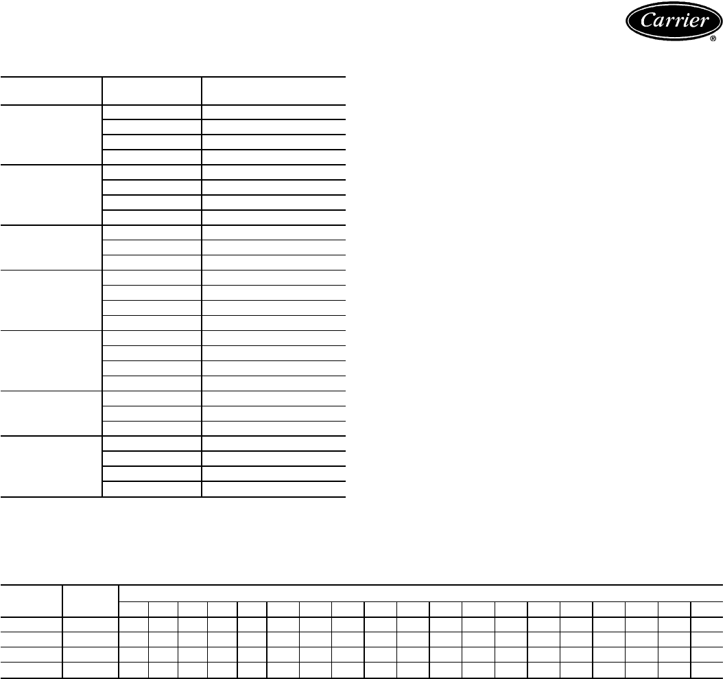
Performance data (cont)
WET COIL PRESSURE DROP
UNIT SIZE AIRFLOW
(cfm) PRESSURE DROP
(in. wg)
018
600 0.069
700 0.082
800 0.102
900 0.116
024
600 0.039
700 0.058
800 0.075
900 0.088
030
900 0.088
1000 0.095
1200 0.123
036
1000 0.068
1200 0.088
1400 0.108
1600 0.123
042
1000 0.048
1200 0.069
1400 0.088
1600 0.102
048
1400 0.068
1600 0.075
1800 0.088
060
1700 0.082
1900 0.095
2100 0.108
2300 0.123
FILTER PRESSURE DROP (in. wg)
UNIT SIZE FILTER
SIZE (in.) CFM
500 600 700 800 900 1000 1100 1200 1300 1400 1500 1600 1700 1800 1900 2000 2100 2200 2300
018, 024 20 x 20 0.05 0.07 0.08 0.10 0.12 0.13 — ————————————
030, 036 20x24————0.09 0.10 0.11 0.13 0.14 0.15 0.16 ————————
042 24x24————— — — —0.110.12 0.14 0.15 ———————
048, 060 24x30————— — — — —0.09 0.10 0.11 0.12 0.13 0.14 0.15 0.16 0.17 0.18
18

Typical piping and wiring
Power Wiring
Control Wiring
Outdoor Airflow
Indoor Airflow
NEC — National Electrical Code
HORIZONTAL DISCHARGE
DOWNFLOW DISCHARGE
CEILING
SUPPLY-AIR
FLEXIBLE DUCT
ROOF-MOUNTING
CURB
ROOF
RETURN-AIR
FLEXIBLE DUCT
19

Application data
Condensate trap — A 2-in. condensate trap must be field
supplied.
Ductwork — Secure downflow discharge ductwork to roof
curb. For horizontal discharge applications, attach duct-
work to unit with flanges.
To convert a unit to downflow discharge or horizon-
tal discharge — Units are equipped with factory-installed
duct covers on both the downflow and horizontal openings.
Remove appropriate duct panel covers for intended dis-
charge application. Units with downflow option do not re-
quire duct panel cover removal.
Airflow — Units are draw-thru on cooling and blow-thru
on heating.
Maximum cooling airflow — To minimize the possibility
ofcondensate blow-off fromevaporator, airflow throughunits
should not exceed 450 cfm/ton.
Minimum cooling airflow is 350 cfm/ton.
Minimum ambient operating temperature in cooling
for all standard units is 40 F. With accessory low ambient
temperature kit, units can operate at temperatures down to
0° F.
20
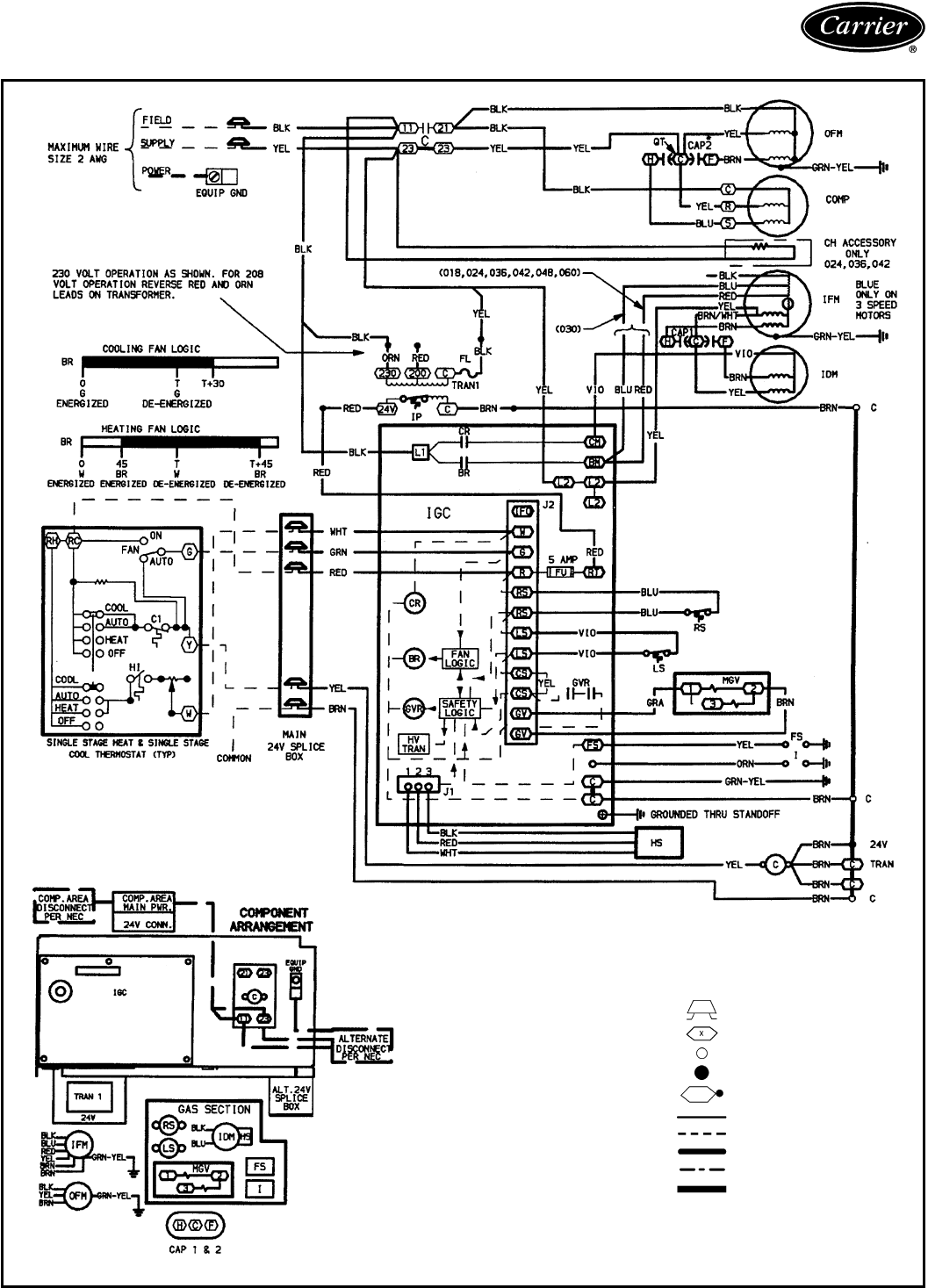
Typical control wiring schematic,
48SS018-060; 208/230-1-60
LEGEND
AWG — American Wire Gage
BR — Blower Relay
C—Contactor
CAP — Capacitor
CH — Crankcase Heater
COMP — Compressor Motor
CR — Combustion Relay
EQUIP — Equipment
FL — Fuse Link
FS — Flame Sensor
FU — Fuse
GND — Ground
GVR — Gas Valve Relay
HS — Hall Effect Sensor
HV TRAN — High-Voltage Transformer
I—Ignitor
IDM — Induced-Draft Motor
IFM — Indoor-Fan Motor
IGC — Integrated Gas Control
IP — Internal Protector
LS — Limit Switch
MGV — Main Gas Valve
NEC — National Electrical Code
OFM — Outdoor-Fan Motor
PWR — Power
QT — Quadruple Terminal
RS — Rollout Switch
TRAN — Transformer
Field Splice
Terminal (Marked)
Terminal (Unmarked)
Splice
Splice (Marked)
Factory Wiring
Field Control Wiring
Field Power Wiring
Accessory or Optional Wiring
To Indicate Common Potential
Only, Not to Represent Wiring
NOTES:
1. If any of the original wire furnished must be replaced, it must be replaced
with type 90 C wire or its equivalent.
2. Use copper conductors only.
21
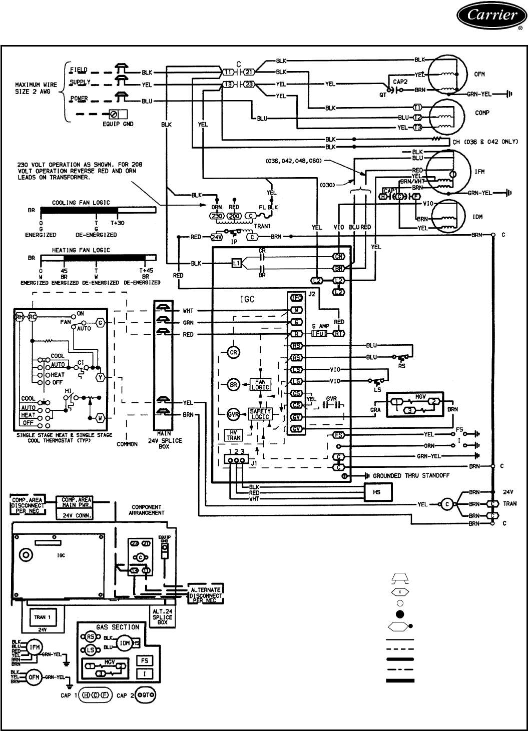
Typical control wiring schematic,
48SS030-060; 208/230-3-60
LEGEND
AWG — American Wire Gage
BR — Blower Relay
C—Contactor
CAP — Capacitor
CH — Crankcase Heater
COMP — Compressor Motor
CR — Combustion Relay
EQUIP — Equipment
FL — Fuse Link
FS — Flame Sensor
FU — Fuse
GND — Ground
GVR — Gas Valve Relay
HS — Hall Effect Sensor
HV TRAN — High-Voltage Transformer
I—Ignitor
IDM — Induced-Draft Motor
IFM — Indoor-Fan Motor
IGC — Integrated Gas Control
IP — Internal Protector
LS — Limit Switch
MGV — Main Gas Valve
NEC — National Electrical Code
OFM — Outdoor-Fan Motor
PWR — Power
QT — Quadruple Terminal
RS — Rollout Switch
TRAN — Transformer
Field Splice
Terminal (Marked)
Terminal (Unmarked)
Splice
Splice (Marked)
Factory Wiring
Field Control Wiring
Field Power Wiring
Accessory or Optional Wiring
To Indicate Common Potential
Only, Not to Represent Wiring
NOTES:
1. If any of the original wire furnished must be replaced, it must be replaced
with type 90 C wire or its equivalent.
2. Use copper conductors only.
22
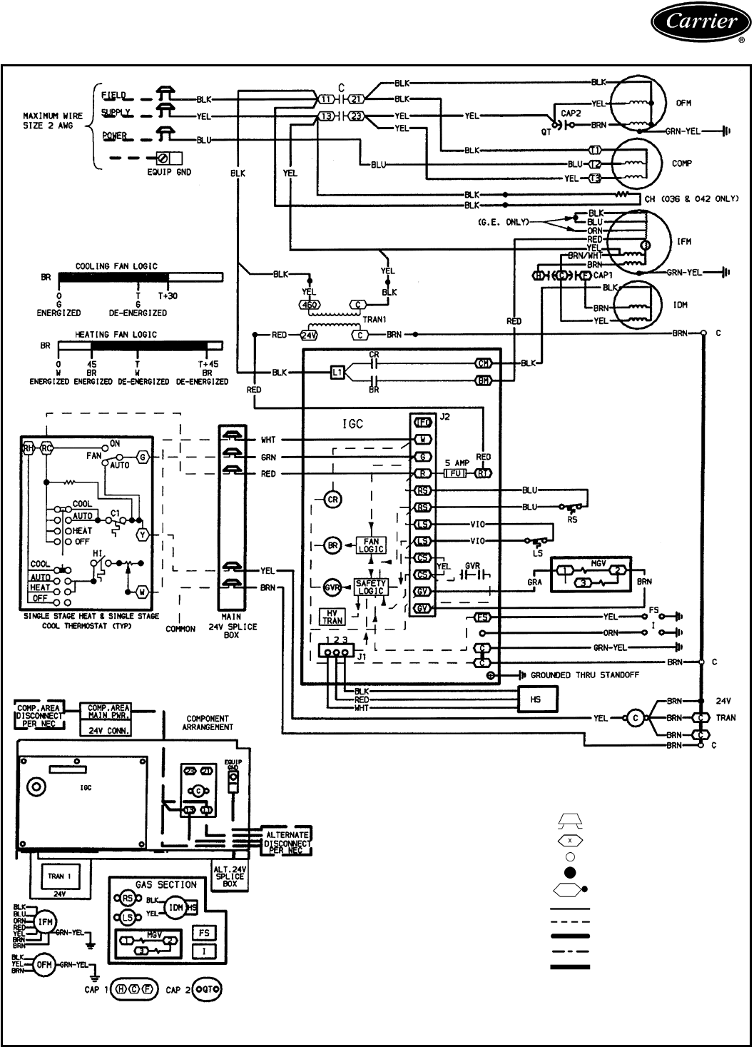
Typical control wiring schematic,
48SS036-060; 460-3-60
LEGEND
AWG — American Wire Gage
BR — Blower Relay
C—Contactor
CAP — Capacitor
CH — Crankcase Heater
COMP — Compressor Motor
CR — Combustion Relay
EQUIP — Equipment
FS — Flame Sensor
FU — Fuse
GND — Ground
GVR — Gas Valve Relay
HS — Hall Effect Sensor
HV TRAN — High-Voltage Transformer
I—Ignitor
IDM — Induced-Draft Motor
IFM — Indoor-Fan Motor
IGC — Integrated Gas Control
LS — Limit Switch
MGV — Main Gas Valve
NEC — National Electrical Code
OFM — Outdoor-Fan Motor
PWR — Power
QT — Quadruple Terminal
RS — Rollout Switch
TRAN — Transformer
Field Splice
Terminal (Marked)
Terminal (Unmarked)
Splice
Splice (Marked)
Factory Wiring
Field Control Wiring
Field Power Wiring
Accessory or Optional Wiring
To Indicate Common Potential
Only, Not to Represent Wiring
NOTES:
1. If any of the original wire furnished must be replaced, it must be replaced
with type 90 C wire or its equivalent.
2. Use copper conductors only.
23
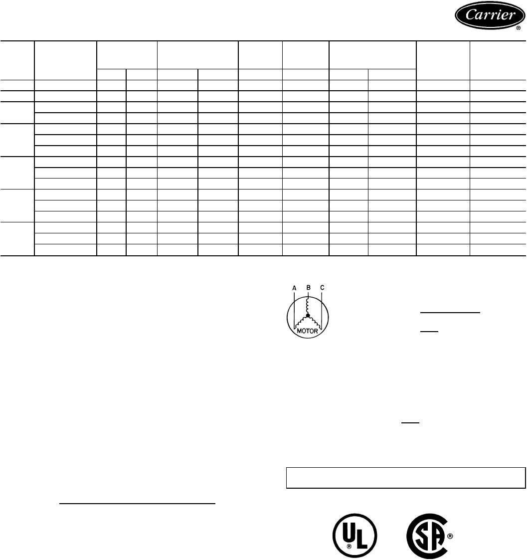
Electrical data
UNIT
48SS V-PH-HZ VOLTAGE
RANGE COMPRESSOR COND
FAN
MOTOR
INDOOR
FAN POWER SUPPLY AWG60C
MIN WIRE
SIZE†
MAX WIRE
LENGTH
(ft)
Min Max RLA LRA FLA FLA MCA MOCP*
018 208/230-1-60 187 253 7.6 45 0.7 1.8 12.0 15 14 75
024 208/230-1-60 187 253 12.4 61 0.7 2.0 18.2 30 12 80
030 208/230-1-60 187 253 14.4 82 1.4 2.0 21.8 30 10 100
208/230-3-60 187 253 9.4 66 1.4 2.0 15.5 25 12 80
036
208/230-1-60 187 253 18.0 96 1.4 2.8 26.7 40 10 90
208/230-3-60 187 253 11.7 75 1.4 2.8 18.8 30 12 65
460-3-60 414 506 5.6 40 0.8 1.4 9.2 10 14 100
042
208/230-1-60 187 253 20.4 104 1.4 4.0 30.9 50 8 100
208/230-3-60 187 253 14.0 91 1.4 4.0 22.9 35 10 85
460-3-60 414 506 6.4 42 0.8 2.0 10.8 15 14 100
048
208/230-1-60 187 253 26.4 129 2.1 5.0 40.1 60 6 100
208/230-3-60 187 253 15.0 99 2.1 5.0 25.9 40 10 75
460-3-60 414 506 8.2 50 1.1 2.3 13.7 20 14 100
060
208/230-1-60 187 253 32.1 169 2.1 6.8 49.0 60 6 100
208/230-3-60 187 253 19.3 123 2.1 6.8 33.0 50 8 90
460-3-60 414 506 10.0 62 1.1 3.2 16.8 25 12 100
LEGEND
AWG — American Wire Gage
CSA — CanadianStandards Association
FLA — Full Load Amps
HACR — Heating, Air Conditioning and
Refrigeration
LRA — Locked Rotor Amps
MCA — Minimum Circuit Amps
MOCP — Maximum Overcurrent Protection
(fuses or HACR-type circuit breaker)
NEC — National Electrical Code
RLA — Rated Load Amps
*Fuse or HACR breaker.
†Minimum wire size is based on 60 C copper wire. If other than 60 C if
used, determine size from NEC. Voltage drop of wire must be less than
2% of rated voltage.
NOTES:
1. In compliance with NEC requirements for multimotor and combina-
tion load equipment (refer to NEC Articles 430 and 440), the over-
current protective device for the unit shall be fuse or HACR breaker.
The CSA units may be fuse or circuit breaker.
2. Unbalanced 3-Phase Supply Voltage
Never operate a motor where a phase imbalance in supply voltage is
greater than 2%.
Use the following formula to determine the percent-
age of voltage imbalance.
% Voltage Imbalance
max voltage deviation from average voltage
= 100 x average voltage
EXAMPLE: Supply voltage is 460-3-60.
AB = 452 v
BC = 464 v
AC = 455 v
452 + 464 + 455
Average Voltage = 3
1371
=3
= 457
Determine maximum deviation from average voltage.
(AB) 457 – 452 = 5 v
(BC) 464 – 457 = 7 v
(AC) 457 – 455 = 2 v
Maximum deviation is 7 v.
Determine percent of voltage imbalance.
7
% Voltage Imbalance = 100 x 457
= 1.53%
This amount of phase imbalance is satisfactory as it is below the
maximum allowable 2%.
IMPORTANT: If the supply voltage phase imbalance is more than
2%, contact your local electric utility company immediately.
24

Controls
Sequence of operation
Heating — On a call for heating, terminal ‘‘W’’ of the ther-
mostat is energized, starting the induced-draft motor. When
the hall-effect sensor on the induced-draft motor senses that
it has reached the required speed, the burner sequence be-
gins. This function is performed by the integrated control
board (IGC). The indoor-fan motor is energized 45 seconds
after flame is established. When the thermostat is satisfied
and ‘‘W’’ is deenergized, the indoor-fan motor stops after a
45-second time-off delay.
Cooling — With the room thermostat SYSTEM switch in
the COOL position and the FAN switch in the AUTO. po-
sition, the cooling sequence of operation is as follows:
When the room temperature rises to a point that is slightly
above the cooling control setting of the thermostat, the ther-
mostat completes the circuit between thermostat terminal
R to terminals Y and G. These completed circuits through
the thermostat connect contactor coil (C) (through unit wire
Y) and blower relay coil (BR) (through unit wire G) across
the 24-v secondary of transformer (TRAN).
The normally-open contacts of energized contactor (C)
close and complete the circuit through compressor motor
(COMP) and condenser (outdoor) fan motor (OFM). Both
motors start instantly.
The set of normally-open contacts of energized relay BR
close and complete the circuit through evaporator blower
(indoor) fan motor (IFM). The blower motor starts
instantly.
The cooling cycle remains ‘‘on’’ until the room tempera-
ture drops to point that is slightly below the cooling
control setting of the room thermostat. At this point, the
thermostat ‘‘breaks’’ the circuit between thermostat termi-
nal R to terminals Y and G. These open circuits deenergize
contactor coil C and relay coil BR. The condenser and com-
pressor motors stop. After a 30-second delay, the blower
motor stops. The unit is in a ‘‘standby’’ condition, waiting
for the next ‘‘call for cooling’’ from the room thermostat.
25

Guide specifications
Packaged Heating/Cooling Units
Constant Volume Application
HVAC Guide Specifications
Size Range: 1
1
⁄
2
to 5 Tons, Nominal Cooling
40,000 to 140,000 Btuh,
Nominal Input Heating
Carrier Model Number: 48SS
Part 1 — General
1.01 SYSTEM DESCRIPTION
Outdoor rooftop mounted, gas heating/electric cool-
ing unit utilizing a rotary, reciprocating, or scroll her-
meticcompressor for cooling duty. Unitshall discharge
supply air downward or horizontally as shown on con-
tract drawings. Outdoor fan/coil section shall have a
blow-thru design for minimum sound levels.
1.02 QUALITY ASSURANCE
A. Unit shall be rated in accordance with ARI Standards
210/240 and 270.
B. Unit shall be designed in accordance with UL Stand-
ard 564.
C. Unit shall be UL listed and CSA certified as a total
package for safety requirements.
D. Roof curb shall be designed to conform to NRCA
Standards.
E. Insulation and adhesive shall meet NFPA 90A re-
quirements for flame spread and smoke generation.
F. Cabinet insulation shall meet ASHRAE standard
no. 62.
1.03 DELIVERY, STORAGE, AND HANDLING
Unit shall be stored and handled per manufacturer’s
recommendations.
Part2—Products
2.01 EQUIPMENT
A. General:
Factory-assembled, single-piece heating and cooling
unit. Contained within the enclosure shall be all fac-
tory wiring, piping, controls, refrigerant charge
(R-22), and special features required prior to field
start-up.
B. Unit Cabinet:
1. Unit cabinet shall be constructed of phosphated,
zinc-coated prepainted steel, capable of withstand-
ing 500 hours in salt spray.
2. Cabinet panels shall be easily removed for
servicing.
3. Indoor blower compartment interior cabinet sur-
facesshall be insulated with aminimum
1
⁄
2
-in.thick,
flexible cleanable insulation, coated on the air side.
Aluminum foil-faced cleanable insulation shall be
used in the entire section.
4. Unit shall utilize a sloped condensate drain pan.
External trap required.
C. Fans:
1. The indoor (evaporator) fan shall be 2- or 3-speed
direct-drive, as shown on equipment drawings.
2. Fan wheel shall be made from steel, be double-
inlet type with forward curved blades with corro-
sion resistant finish and be dynamically balanced.
3. Outdoor (condenser) fan shall be of the direct
driven, propeller type with aluminum blades riv-
eted to corrosion resistant steel spiders, be dy-
namically balanced, and discharge air vertically
upwards and horizontally.
D. Compressor:
1. Fully hermetic compressor with factory-installed vi-
bration isolation.
2. Rotary compressors shall be standard on unit
size018. Reciprocating compressorsshall be stand-
ardon unit sizes 024-042. Scroll compressors shall
be standard on unit sizes 048 and 060.
E. Coils:
Evaporator and condenser coils shall have aluminum
plate fins mechanically bonded to seamless copper
tubes with all joints brazed. Tube sheet openings shall
be belled to prevent tube wear.
F. Heating Section:
1. Induced-draft combustion type with energy saving
direct spark ignition system and redundant main
gas valve.
2. Induced-draft motors shall be provided with solid-
state hall effects sensor to ensure adequate airflow
for combustion.
3. The heat exchangers shall be constructed of alu-
minized steel for corrosion resistance.
4. Burners shall be of the in-shot type constructed of
aluminum coated steel.
5. Integrated gas control board shall provide control
of heating and simplify troubleshooting through
its built-in diagnostic function. The IGC shall pro-
vide timed control of indoor-fan functioning and
burner ignition. A light-emitting diode (LED) shall
provide diagnostic information. The IGC board
shall also contain anti-short cycle protection for
gas heat operation.
6. All gas piping and electric power shall enter the
unit cabinet at a single location.
G. Refrigerant Components:
Refrigerant components shall be of the Acutrol™ feed
system type.
H. Controls:
Unit shall be complete with self-contained low-voltage
control circuit.
26

I. Operating Characteristics:
1. Unit shall be capable of starting and running at
125 F ambient outdoor temperature per maxi-
mum load criteria of ARI Standard 210/240.
2. Compressor with standard controls shall be ca-
pable of operation in cooling down to 40 F am-
bient outdoor temperature.
3. Unit provided with fan time delay to prevent cold
air delivery before heat exchanger warms up.
4. Unit provided with fan time-delay after the ther-
mostat is satisfied.
J. Electrical Requirements:
All unit power wiring shall enter unit cabinet at a single
location.
K. Motors:
1. Compressor motors shall be of the refrigerant-
cooled type with line break thermal and current
overload protection.
2. All fan motors shall have permanently lubricated-
bearings and inherent automatic reset thermal
overload protection.
3. Condenser-fan motor shall be totally enclosed.
L. Special Features:
1. Roof Curb:
Curb shall have seal strip and a wood nailer for
flashing and shall be installed per manufacturer’s
instructions.
2. 25% Open Manual Outdoor-Air Damper:
Manual damper package shall consist of damper,
birdscreen, and rainhood which can be preset
to admit outdoor air for year-round ventilation.
3. Thermostat and Subbase:
To provide for one-stage heating and cooling
in addition to manual or automatic changeover
and fan control.
4. Electronic Programmable Thermostat:
Thermostat provides 2-stage heating and 2-stage
cooling control with remote communication
ability.
5. Natural-to-Propane Conversion Kit:
Kit shall be complete with burner orifice(s).
6. Low Ambient Package:
Package shall consist of a solid-state control and
condenser coil temperature sensor for control-
ling outdoor-fan motor operation, which shall al-
low unit to operate down to 0° F outdoor ambi-
ent temperature.
7. Compressor Short-Cycle Protection:
Solid-state control shall protect compressor by
preventing short cycling.
8. Lifting Bracket Kit:
Kit shall provide attachment points for rigging
straps. (Not required with optional base rail or
downflow option applications.)
9. High- and Low-Pressure Switch Kits:
Switches provide additional safety features and
protect the unit from running at unsuitable
pressures.
10. Filter Rack:
Rack provides mounting location for filters when
unit is in downflow application.
11. Crankcase Heater:
Heater warms crankcase oil to reduce refriger-
antmigration(recommendedon208/230-v,single-
phase units in sizes 024-042).
12. Base Rail:
Base rail provides holes for rigging and handling,
and an elevated base for horizontal applications.
13. Downflow Option:
Option provides for vertical ductwork connec-
tions. Unit shall be equipped with base rail.
14. High Altitude Kit:
Kit shall have new burner orifices for use in ap-
plications from 2001 to 5000 feet.
15. Low NO
x
Kit:
Kit shall provide low NO
x
emissions for units be-
ing installed in California Air Quality Manage-
ment Districts which require NO
x
emissions of
40 nanograms/joule or less.
27
Carrier Corporation • Syracuse, New York 13221 9-98
Manufacturer reserves the right to discontinue, or change at any time, specifications or designs without notice and without incurring obligations.
Book 1 4
Tab 1a 6a
Page 28 Catalog No. 524-890 Printed in U.S.A. PC 111 Form 48SS-4PD
Replaces: 48SS-3PD
