Carrier 50Ah Users Manual 6pd
50AH to the manual 48f8edfe-009b-45b2-9947-a407b0121366
2015-01-24
: Carrier Carrier-50Ah-Users-Manual-310462 carrier-50ah-users-manual-310462 carrier pdf
Open the PDF directly: View PDF ![]() .
.
Page Count: 16
Copyright 2002 Carrier Corporation Form 50AH-6PD
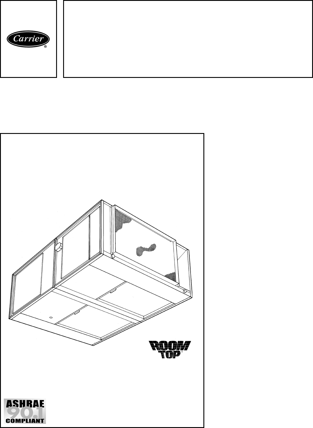
Single Package Cooling Units
Featuring:
• compact design
• flexibility
• easy maintenance
• high quality and reliability
• quiet and efficient scroll compressor
technology
Features/Benefits
All in one package — high
cooling efficiency,
installation convenience,
ease of accessibility for time-
saving maintenance.
Space and cost saving design
Model 50AH is specifically designed to
provide the building owner with truly out-
of-sight cooling, because it installs inside
the ceiling. That’s why we call it the Car-
rier ROOMTOP®unit. The compact de-
sign and low silhouette enable it to fit
easily and securely above the conditioned
space. Single-package construction
makes it easy to install with minimal time
and cost.
Application flexibility
If desired for particular applications, the
unit can also be installed as a split system
with the condenser section mounted hor-
izontally. Centrifugal fans permit ducting
of both evaporator and condenser air.
Quiet operation
Commercial end users appreciate the ex-
tra comfort of quiet operation. Carrier
engineers met the challenge by specify-
ing heavy insulation, vibration-resistant
construction and operating components
that function at low noise levels, all of
which keep system sound at a minimum
level.
Easy maintenance
When it comes to maintenance, the
50AH rates high in accessibility. Indoor
50AH
Horizontal Indoor
Single-Package
Cooling Units
2to5NominalTons
Product
Data
2
location is ideal for the maintenance
technician, and five access panels, easily
removed, provide quick and convenient
access to all components when needed.
As an added plus, all required service/
maintenance access can be from one
side allowing the unit to be located
against a wall or ceiling plenum obstruc-
tion, an obvious space-saving idea.
Carrier quality and reliability
The Carrier 50AH ROOMTOP®units
have much to offer the cost- and
efficiency-conscious commercial owner.
Every unit is thoroughly run tested at the
factory and equipped with safety controls
designed to monitor and protect over the
life of the unit.
Scroll compressor technology
Scroll compressors are designed for high
efficiency and are internally spring
mounted to minimize vibration noise.
Each compressor is hermetically sealed
against contamination to promote longer
life and dependable operation. Scroll
compressors are standard on all units.
Table of contents
Page
Features/Benefits . . . . . . . . . . . . . . . . . . . . . . . . . . . . . . . . . . . . . . . . . . . . .1,2
Model Number Nomenclature . . . . . . . . . . . . . . . . . . . . . . . . . . . . . . . . . . . . . . 2
ARI Capacity Ratings . . . . . . . . . . . . . . . . . . . . . . . . . . . . . . . . . . . . . . . . . . . . 2
Physical Data . . . . . . . . . . . . . . . . . . . . . . . . . . . . . . . . . . . . . . . . . . . . . . . . . 3
Field-Installed Accessories . . . . . . . . . . . . . . . . . . . . . . . . . . . . . . . . . . . . . . . . 4
Base Unit Dimensions . . . . . . . . . . . . . . . . . . . . . . . . . . . . . . . . . . . . . . . . . . . 5
Selection Procedure . . . . . . . . . . . . . . . . . . . . . . . . . . . . . . . . . . . . . . . . . . . . 6
Performance Data . . . . . . . . . . . . . . . . . . . . . . . . . . . . . . . . . . . . . . . . . . . . . 6-9
Controls . . . . . . . . . . . . . . . . . . . . . . . . . . . . . . . . . . . . . . . . . . . . . . . . . . . . . 9
Electrical Data . . . . . . . . . . . . . . . . . . . . . . . . . . . . . . . . . . . . . . . . . . . . . . 9,10
Typical Wiring Schematic . . . . . . . . . . . . . . . . . . . . . . . . . . . . . . . . . . . . . . 11,12
Typical Piping and Wiring . . . . . . . . . . . . . . . . . . . . . . . . . . . . . . . . . . . . . . . 13
Application Data . . . . . . . . . . . . . . . . . . . . . . . . . . . . . . . . . . . . . . . . . . . . . . 13
Guide Specifications . . . . . . . . . . . . . . . . . . . . . . . . . . . . . . . . . . . . . . . . 14,15
Model number nomenclature
ARI* capacity ratings
LEGEND
*Air-conditioning and Refrigeration Institute.
†TDR is standard.
NOTES:
1. Ratings are at zero condenser air static and rated in
accordance with ARI Standard 210.
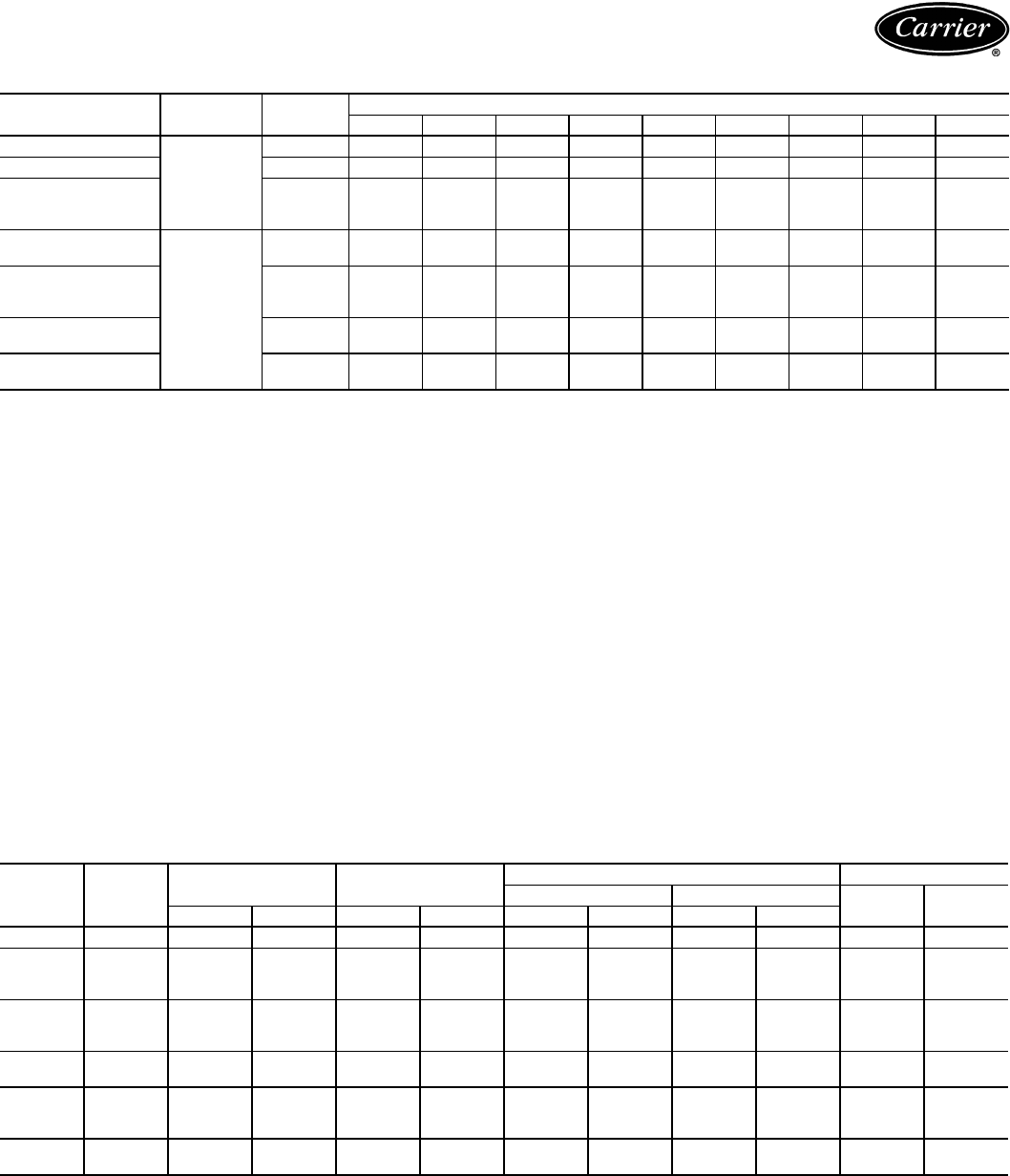
UNIT
50AH V-PH-Hz TOTAL
kW
NET TOTAL
COOLING CAP. (Btuh)
NOMINAL
CFM EER SEER SEER
(with TDR)
SOUND RATING
(dB)
024 230-1-60 2.56 24,800 800 — — 10.50† 78
036
230-1-60
4.3 36,000 1200
— 10.00 10.00
82208/230-3-60 8.40 — —
460-3-60 8.40 — —
048
230-1-60
5.63 49,500 1600
—— 10.00†
82208/230-3-60 8.80 — —
460-3-60 8.80 — —
060
230-1-60
6.9 58,500 2000
—9.7010.00
82208/230-3-60 8.50 — —
460-3-60 8.50 — —
dB — Decibels
EER — Energy Efficiency Ratio
SEER — Seasonal Energy Efficiency Ratio
TDR — Time-Delay Relay 2. EER = NET CAPACITY (Btuh)
TOTAL WATTS
Indoor Fan Motor
– – Standard Motor
M – 1.5 hp Optional Motor
FIOP*
50AH–048–M–541XX
Model Designation –
50AH Horizontal,
Indoor Single-Package
Cooling Unit
Packaging
1 – Domestic
2 – Export
Design Revision
Voltage
3 – 230-1-60
5 – 208/230-3-60
Nominal Tons
024 – 2
036 – 3
048–4
060–5
6 – 460-3-60
*FIOP — Factory-Installed option, contact your Carrier representative for details.
®
I
S
O
9
0
0
1
:
2
0
0
0
#
A
2
3
2
5
Quality Assurance
3
LEGEND
*Shipping weights include base unit plus packaging.
†If components are to be split, additional refrigerant will be needed.
**Two-speed motor.
††Use Type L copper only.
NOTE: If components are to be split, the maximum length of refrigerant tubing to be
used is 50 equivalent ft, assuming components will be installed in same horizontal plane.
If components are not to be installed in same horizontal plane, contact your Carrier rep-
resentative for more information. For additional piping information, refer to Carrier
System Design Manual, Part 3.
UNIT 50AH 024 036 048 060
SHIPPING WEIGHT (lb)* 560 590 690 700
OPERATING WEIGHT (lb)
Base Unit, Evaporator/Condenser Section 450, 193/256 480, 206/274 580, 250/330 590, 254/336
REFRIGERANT TYPE R-22
Operating Charge (lb)† 5.4 5.5 7.4 7.6
COMPRESSOR — TYPE Scroll
Quantity...Model (1)...ZR23 (1)...ZR34 (1)...SR48 (1)...ZR57
Oil (oz) 24 42 70 54
HPS Setting (psig)
Cutout 426 ± 7
Reset 320 ± 20
LPS Setting (psig)
Cutout 27 ± 4
Reset 67 ± 7
CONDENSATE DRAIN CONNECTION
Size (in.)...Type
3
/
4
...FPT
CONDENSER COIL Copper Tubes — Aluminum Fins
Size (L xH) (in.) 40 x 15 40 x 16 40 x 22
Number of Rows...Fins/in. 4...13.6 4...17 4...13.6
CONDENSER FAN Centrifugal — Direct Drive Centrifugal — Belt Drive
Nominal Cfm 1350 1350 2250 2450
Maximum Rpm 1100 1500
Blower Size (in.) 12 x 6 12 x 9
Pulley Pitch Diameter (in.)
Blower None 5.0 6.0 6.0
Motor (Variable) None 2.4-3.4 1.9-2.9 2.4-3.4
Motor Hp
1
/
2
3
/
4
11
1
/
2
Motor Rpm 825 1725 1725 1725
EVAPORATOR COIL Copper Tubes — Aluminum Fins
Size (L xH) (in.) 34 x 15 34 x 16 34 x 22
Number of Rows...Fins/in. 4...14.4 4...15 4...14.4
EVAPORATOR AIR FAN (Standard) Centrifugal — Direct Drive
Nominal Cfm 800 1200 1600 2000
MaxRpm 1100 1150 900/1050**
Blower Size (in.) 10 x 5 10 x 6 10 x 6
Motor Hp (Rpm)
1
/
6
(850)
1
/
2
(1075)
3
/
4
(1050)
EVAPORATOR AIR FAN (Optional)
Not
Available
Centrifugal Belt Drive
Nominal Cfm 1600 2000
MaxRpm 1300
Blower Size (in.) 10 x 8
Motor Hp 1
1
/
2
Motor Rpm 1725
Pulley Pitch Diameter (in.)
Blower 4.2
Motor (Variable) 2.4-3.4
INDOOR-AIR FILTERS Factory-Supplied Cleanable Type
Number...Size (in.) 1...14 x 34 x 1 1...21 x 34 x 1
INTERCONNECTING TUBING SIZE (in.)††
Hot Gas
1
/
2
1
/
2
1
/
2
1
/
2
Liquid
3
/
8
3
/
8
3
/
8
3
/
8
HPS — High-Pressure Switch
LPS — Low-Pressure Switch
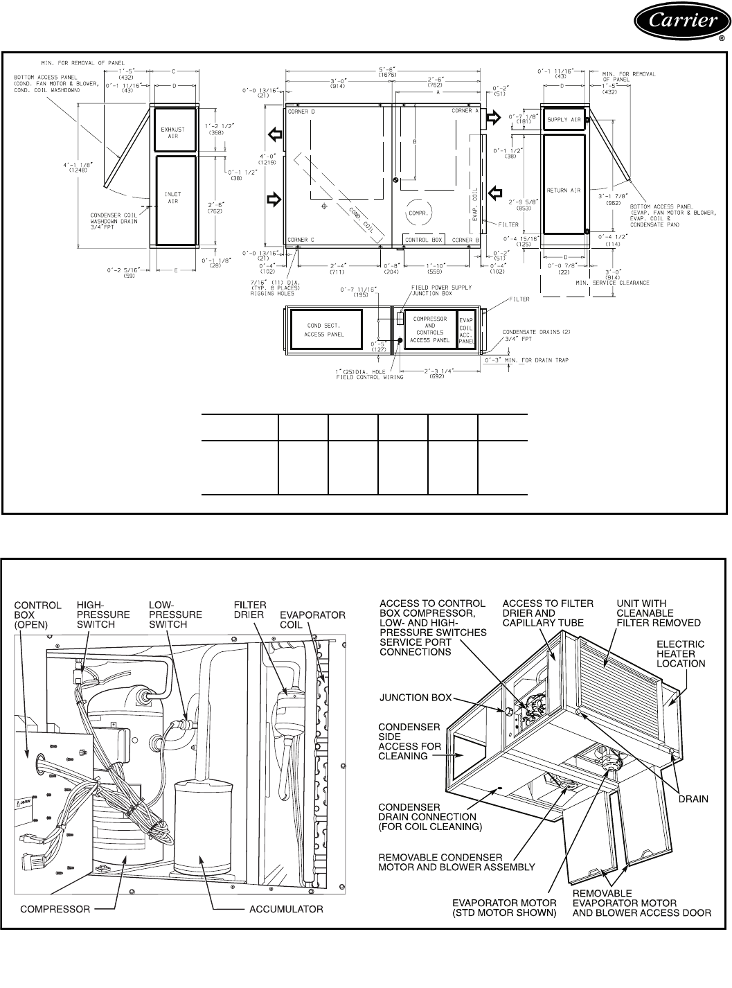
Physical data
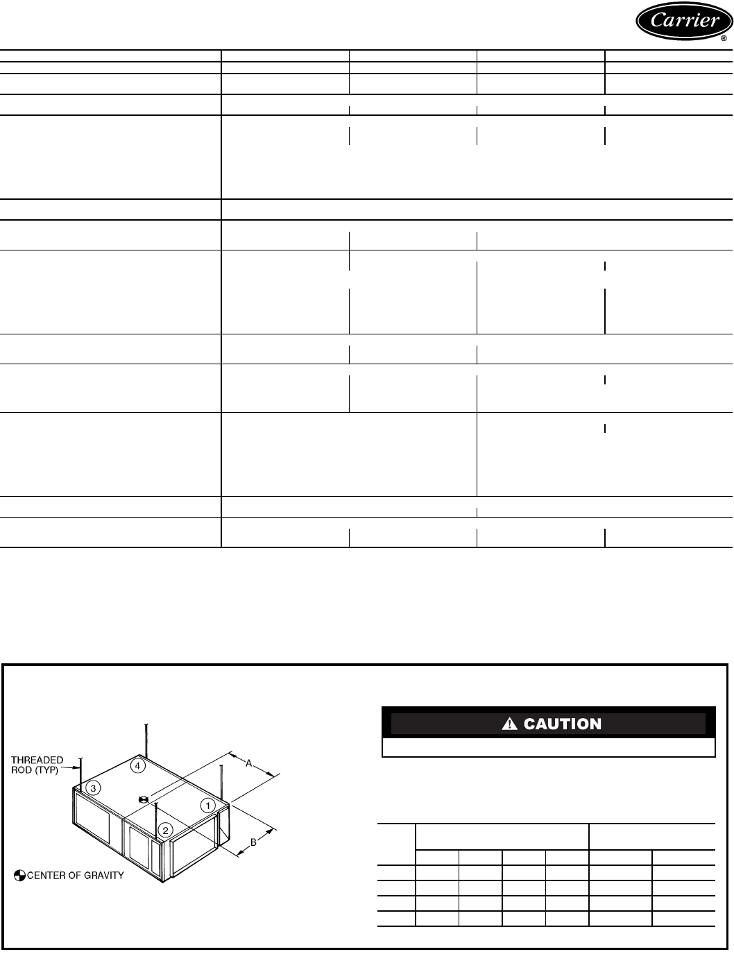
NOTE: Fasten threaded rods through holes in end frames. Use 2 rods
on each side of unit for a total of 4.
OPERATING WEIGHT DISTRIBUTION AND
CENTER OF GRAVITY
All panels must be in place when rigging.
UNIT
50AH
WEIGHT (lb/kg)
OF CORNER
DIMENSIONS
(ft-in./mm)
1234 A B
024 93/42 108/49 139/63 120/54 2-5 /737 2-1
5
/
8
/651
036 95/43 113/51 148/67 124/56 2-4
3
/
4
/730 2-2 /660
048 112/51 143/65 183/83 142/64 2-5 /737 2-3 /686
060 114/52 143/65 186/84 147/67 2-4
3
/
4
/730 2-2
3
/
4
/679
4
Thermostat and subbase — Attractive wall-mounted
24-v accessory provides precise temperature control.
Automatic and Manual changeover models available. A
thermostat subbase is available that works with Cycle-
LOC™ circuitry. If a safety device trips, compressor locks
out and subbase warning light (LK OUT) alerts occupant.
Three models available: One stage cool/two stage heat;
two stage cool/two stage heat; one stage cool/one stage
heat.
Time Guard®II circuit (standard on single-phase
units) — Time Guard II device prevents short cycling of
compressor if thermostat is rapidly changed; automatically
prevents compressor from restarting for 5 minutes after
shutdown.
Electric heaters — A wide range of models is available
from 5 to 30 kW, 208-, 240- and 480-v, single- and 3-ph
units. The heaters mount easily on 50AH discharge open-
ing. The heater control box is accessible from the bottom
of heater.
Condensate pump — The condensate pump is used
when the distance and slope to the nearest drain is far
enough to prevent the natural drainage of unit. The pump
is mounted remotely from the unit and includes a signal
light (field-installed) which illuminates when the reservoir
rises beyond a certain level. The unit automatically shuts
down when this reservoir level is achieved.
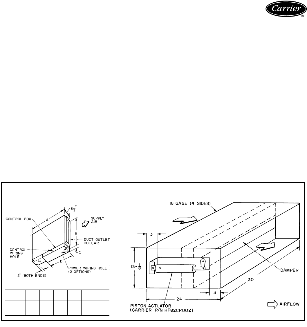
Head pressure control damper — This accessory is
duct mounted and allows unit to mechanically cool down to
0° F.
Damper dimensions fit 024, 036 sizes.
NOTE: For use with 048 and 060 size units, ductwork
from unit to damper must be reduced in size to fit damper
dimensions.
Vibration isolators — Package of four isolators used for
dampening any unit vibration so that vibrating sounds are
not transmitted to building structure. Isolators are spring,
ceiling type.
Field-installed accessories
88EN ELECTRIC HEAT MODULE
ACCESSORY
DIMENSIONS (in.)
UNIT
50AH ABCD DUCT
OPENING
024,036 13
1
/
2
16 2
1
/
2
8
1
/
2
7
1
/
8
x14
048,060 24 21
3
/
4
3197
1
/
8
x20
7
/
8
HEAD PRESSURE CONTROL DAMPER (in.)
5
Base unit dimensions
DIMENSIONS (ft-in.)
UNIT
50AH ABCDE
024 2-5 2-1
5
/
8
1- 5
3
/
4
1-2 1-1
036 2-4
3
/
4
2-2 1- 5
3
/
4
1-2 1-1
048 2-5 2-3 1-11
5
/
8
1-8
7
/
8
1-7
7
/
8
060 2-4
3
/
4
2-2
3
/
4
1-11
5
/
8
1-8
7
/
8
1-7
7
/
8
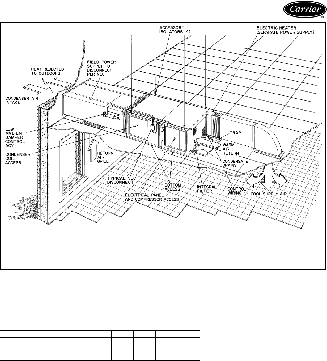
UNIT COMPONENT LOCATIONS
6
I Determine cooling requirements at design
conditions.
Given:
Gross Cooling Capacity
Required (TC) . . . . . . . . . . . . . . . . . .39,000 Btuh
Sensible Heat Capacity (SHC) . . . . . .30,500 Btuh
Temperature of Air Entering Condenser . . . . .95 F
Temperature of Air Entering
Evaporator . . . . . . . . . . . . . . . 80 F edb/67 F ewb
Evaporator Air Quantity. . . . . . . . . . . . 1,200 cfm
External Static Pressure:
Condenser . . . . . . . . . . . . . . . . . . .0.50 in. wg
Evaporator (includes static pressure
drop of factory-supplied filter
of 0.06 in. wg) . . . . . . . . . . . . . . .0.20 in. wg
II Select unit based upon required cooling
capacity.
Enter cooling capacity table at temperature of air
entering condenser of 95 F. The 50AH036 unit at
1200 cfm and 67 F ewb will provide a Total
Capacity (TC) of 44,200 Btuh and a Sensible Heat
Capacity (SHC) of 31,300 Btuh. Since the entering
air is 80 F edb, an SHC correction is not required.
III Determine evaporator fan performance.
Enter Evaporator Fan Performance table at
1200 cfm and 50AH036 data. The external static
pressure shown (0.23 in. wg) will exceed the
0.20 in. wg required. The fan motor will require
0.52 kW.
IV Determine condenser fan performance and
motor pulley setting requirements.
Enter Condenser Fan Performance table at
the selected cfm and required static pressure of
0.50 in. wg. The fan motor will require 0.73 kW
and the motor pulley should be set at 2 turns open
at 1350 cfm of condenser air required.
NOTE: Unit 50AH024 contains a direct-drive con-
denser fan assembly.
Performance data
GROSS COOLING CAPACITIES
See Legend on page 7.
50AH024
Temp
Air Ent
Condenser
(F)
Evaporator Air Quantity — Cfm/BF
600/0.02 800/0.03 1000/0.04
Evaporator Air Ewb Temp (F)
726762 726762 726762
85
TC 27.1 25.3 23.0 27.7 26.4 24.6 27.8 26.9 25.8
SHC 13.5 17.0 20.2 14.7 19.4 23.7 15.6 21.5 25.8
kW 1.64 1.62 1.61 1.65 1.63 1.62 1.65 1.64 1.63
95
TC 26.6 24.5 20.8 27.4 25.8 22.9 28.0 26.5 25.2
SHC 13.4 16.7 19.1 14.7 19.4 22.8 16.0 21.7 25.2
kW 1.85 1.84 1.80 1.86 1.85 1.82 1.87 1.85 1.84
105
TC 25.8 22.3 18.4 27.1 24.5 21.2 27.7 25.6 23.6
SHC 13.1 15.8 17.9 14.7 18.9 21.2 16.2 21.5 23.6
kW 2.09 2.05 1.99 2.11 2.08 2.04 2.12 2.10 2.07
115
TC 24.6 19.9 16.5 26.1 22.0 19.8 26.8 23.6 22.3
SHC 12.7 14.8 16.5 14.4 17.9 19.8 16.0 20.7 22.3
kW 2.36 2.29 2.22 2.39 2.33 2.29 2.39 2.35 2.33
50AH036
Temp
Air Ent
Condenser
(F)
Evaporator Air Quantity — Cfm/BF
900/0.011050/0.011200/0.02
Evaporator Air Ewb Temp (F)
726762 726762 726762
85
TC 45.0 41.1 37.3 45.8 42.3 38.6 46.5 43.4 39.8
SHC 22.5 27.7 32.6 23.6 29.9 35.6 24.6 32.0 38.3
kW 3.19 3.07 2.96 3.22 3.11 3.00 3.25 3.14 3.04
95
TC 43.0 38.8 34.3 44.1 40.1 35.8 45.0 44.2 37.4
SHC 21.8 26.8 31.1 23.1 29.1 34.1 24.4 31.3 36.8
kW 3.42 3.28 3.15 3.46 3.33 3.20 3.49 3.37 3.25
105
TC 40.4 35.8 29.6 41.6 37.1 31.3 42.6 38.2 33.2
SHC 20.9 25.6 28.5 22.3 27.9 30.8 23.7 30.2 33.2
kW 3.63 3.48 3.38 3.68 3.53 3.44 3.73 3.58 3.49
115
TC 37.7 30.6 25.8 38.7 31.6 37.8 39.7 32.8 29.7
SHC 19.9 23.3 25.8 21.3 25.5 27.8 22.7 27.8 29.7
kW 3.85 3.71 3.59 3.90 3.76 3.67 3.94 3.80 3.73
Selection procedure (with example)
7
GROSS COOLING CAPACITIES (cont)
LEGEND
NOTES:
1. Performance based on nominal condenser airflow listed in physical data table
on page 3.
2. SHC is based on 80 F db temperature of air entering the coil.
Below 80 F db, subtract (corr factor x cfm) from SHC.
Above 80 F db, add (corr factor x cfm) to SHC.
Correction Factor = 1.10 x (1 – BF) x db – 80)
The following formulas may be used:
Where:
h
ewb
= Enthalpy of air entering evaporator coil
EVAPORATOR FAN PERFORMANCE
LEGEND
*Standard direct drive indoor (evaporator) fan motor (IFM). For optional
belt drive IFM performance, see table on page 8.
NOTES:
1. Above fan performance is based on wet coil and deducted casing
losses, and clean factory-installed permanent cleanable filter.
2. Evaporator fans are direct drive (except 048, 060 special order
evaporator-fan motor option). Refer to Belt Drive Evaporator Fan
Performance table on page 8.
3. Interpolation is permissible, do not extrapolate.
4. For units installed with accessory electric heaters, see Electric
Heater Static Pressure Drop table for additional performance losses.
50AH048
Temp
Air Ent
Condenser
(F)
Evaporator Air Quantity Cfm/BF
1200/0.06 1600/0.08 2000/0.10
Evaporator Air Ewb Temp (F)
726762 57726762 57726762 57
85
TC 56.0 52.1 47.9 44.4 57.7 54.5 50.6 49.6 59.4 56.0 52.7 52.3
SHC 27.8 34.8 41.6 44.4 30.2 39.6 48.0 49.6 32.8 43.9 52.5 52.3
kW 3.77 3.68 3.59 3.53 3.81 3.74 3.66 3.64 3.85 3.77 3.70 3.69
95
TC 54.0 50.1 45.7 42.4 55.7 52.3 48.6 47.3 57.4 53.8 51.0 50.9
SHC 27.1 34.0 40.4 42.4 29.6 38.8 47.0 47.3 32.4 43.2 50.9 50.9
kW 4.21 4.11 4.01 3.95 4.25 4.18 4.09 4.07 4.31 4.21 4.15 4.15
105
TC 51.8 47.9 42.3 40.2 53.6 50.0 45.1 45.0 54.6 51.4 48.9 48.6
SHC 26.3 33.1 38.8 40.2 29.0 38.0 44.8 45.0 31.3 42.4 48.9 48.6
kW 4.69 4.58 4.45 4.40 4.75 4.65 4.54 4.53 4.77 4.69 4.63 4.63
115
TC 49.5 45.5 38.6 37.7 51.2 47.6 41.9 42.1 52.2 49.1 45.8 45.8
SHC 25.5 32.2 37.0 37.7 28.3 27.3 41.8 42.1 30.7 42.0 45.8 45.8
kW 5.21 5.09 4.92 4.89 5.27 5.17 5.03 5.03 5.30 5.23 5.14 5.14
BF — Bypass Factor
Ewb — Entering Wet-Bulb
kW — Compressor Motor Power Input (kilowatts)
SHC — Gross Sensible Heat Capacity (1000 Btuh)
TC — Gross Total Cooling Capacity (1000 Btuh)
BYPASS
FACTOR
(BF)
ENTERING AIR DRY-BULB TEMPERATURE (F)
79 7877 7675Under75
8182 83 84 85 Over 85
Correction Factor
.025 1.07 2.12 3.19 4.25 5.32
Use formula
shown below
.05 1.04 2.07 3.11 4.14 5.18
.10.98 1.96 2.94 3.92 4.90
.20 .87 1.74 2.62 3.49 4.36
.30 .76 1.53 2.29 3.05 3.82
.35 .71 1.42 2.13 2.83 3.54
50AH060
Temp
Air Ent
Condenser
(F)
Evaporator Air Quantity — Cfm/BF
1500/0.06 2000/0.092250/0.10
Evaporator Air Ewb Temp (F)
726762 726762 726762
85
TC 64.8 58.5 52.9 68.0 61.5 56.3 68.9 62.5 58.0
SHC 33.2 41.1 48.5 37.2 47.3 55.7 38.9 50.0 57.7
kW 4.49 4.29 4.13 4.59 4.83 4.22 4.62 4.41 4.27
95
TC 61.9 55.7 50.2 65.1 58.7 54.0 66.1 59.7 55.8
SHC 32.3 40.1 47.3 36.4 46.5 54.0 38.2 49.3 55.8
kW 4.94 4.72 4.57 5.04 4.81 4.67 5.07 4.84 4.72
105
TC 58.5 52.4 47.2 61.5 55.2 51.4 62.6 56.3 53.3
SHC 31.1 38.8 45.8 35.2 45.2 51.4 37.1 48.1 58.2
kW 5.41 5.20 5.04 5.51 5.28 5.16 5.55 5.32 5.22
115
TC 54.9 49.0 44.1 57.8 51.7 48.7 58.7 52.6 50.4
SHC 29.8 37.5 44.0 34.0 43.9 48.7 35.9 46.7 50.4
kW 5.93 5.72 5.56 6.04 5.80 5.70 6.07 5.83 5.75
t
ldb
=t
edb
–sensible capacity (Btuh)
1.10 x cfm
t
lwb
= Wet-bulb temperature corresponding to enthalpy of air leaving
evaporator col (h
lwb
).
h
lwb
=h
ewb
–total capacity (Btuh)
4.5 x cfm
CFM
UNIT SIZE — 50AH
024 036 048* 060*
ESP Fan kW ESP Fan kW ESP Fan kW ESP Fan kW
600 .60.20——————
700 .54.22——————
800 .43.24——————
900 .29.26.69.44————
1000 .11.29.57.46————
1100 — — .42 .49 1.10 .45 1.11 .52
1200 — — .23 .52 1.01 .49 1.045 .55
1300 ————.90.51.97.57
1400 ————.79.55.88.59
1500 ————.67.58.78.62
1600 ————.54.61.67.64
1700 ————.39.64.53.67
1800 ————.22.67.52.70
1900 ————.03.70.40.74
2000 —————— .28.78
ESP — External Static Pressure (in. wg)
kW — Total Fan Motor Power Input (kilowatts)
Performance data (cont)
8
BELT DRIVE EVAPORATOR FAN PERFORMANCE
(Special Order Only, Pricing and
ordering on related price pages.)
LEGEND
NOTE: Pulley setting must be adjusted to limit cfm to 450 cfm/ton
maximum.
Unit operation beyond that limit may result in blow-off and
condensate problems.
CONDENSER FAN PERFORMANCE
LEGEND
kW — Total Fan Motor Power Input (kilowatts)
NOTES:
1. Above fan performance is based upon coil and deducted casing
losses only.
2. External static pressure (ESP) is measured in inches water gage
(in. wg).
3. Interpolation is permissible. Do not extrapolate.
4. Condenser fan on unit size 024 only, is direct drive.
5. Minimum one turn open of motor pulley is required on unit sizes 036
and 060.
6. Number of turns open applies to field setting of motor pulley.
7. Factory setting as follows: 036, 4 turns open;048, 2 turns open;060,
5 turns open.
8. Care should be taken when hoods and/or louvers are installed to
avoid condenser air recirculation.
CFM
UNIT SIZE — 50AH
048 060
ESP Fan kW ESP Fan kW
1800 ————
1850 ————
1900 ————
1950 .81 1.03 — —
2000 .72 1.05 — —
2050 .63 1.07 — —
2100 .55 1.08 1.02 1.17
2150 .47 1.11 .93 1.21
2200 .42 1.14 .84 1.24
2250 .34 1.17 .75 1.27
ESP — External Static Pressure (in. wg)
kW — Total Fan Power Motor Input (kilowatts)
UNIT
50AH
COND
CFM
EXTERNAL STATIC PRESSURE (in. wg)
0.0 0.10.2 0.3 0.4 0.5 0.6
Turns kW Turns kW Turns kW Turns kW Turns kW Turns kW Turns kW
024
1525 Note 4 .66 ————————————
1475 — — Note 4 .64 ——————————
1400 ————Note4.63————————
1350 ——————Note4.62——————
1300 ————————Note4.62————
036
1650 2 .84 ————————————
1600 — — 2 .82 ——————————
1550 ———— 2 .80————————
1500 3 .72 ———— 2 .781 .84————
1450 4 .63 3 .70 ———— 2 .761 .83——
1400 — — 4 .61 3 .68 —————— 1 .81
1350 5 .51 ———— 3 .67—— 2 .73——
1300 — — 5 .50 4 .57 — — 3 .65 — — 2 .71
048
2700 2 .90 ————————————
2600 — — 2 .87 ——————————
2550 3 .81 ————————————
2450 — — 3 .77 2 .83 1 .89 ——————
2350 —————— 2 .801 .86————
2300 4 .68 — — 3 .74 ———— 0 .90——
2200 — — 4 .66 ———— 2 .771 .820 .86
060
3100 3 1.34 ————————————
3000 — — 3 1.32 ——————————
2900 —————— 21.39——————
2850 4 1.11 — — 3 1.24 ————————
2750 — — 4 1.07 ———— 21.32————
2700 —————— 31.17——————
2650 ———————————— 11.37
2600 5 .95 — — 4 1.01 ———— 21.26——
2550 ———————— 31.12————
2500 — — 5 .92 ——————————
2450 —————— 4 .97———— 21.21
2400 ———— 5 .90———— 31.08——
Performance data (cont)
9
ELECTRIC HEATER STATIC PRESSURE DROP (in. wg)
NOTE: Above electric heaters are
not
UL (Underwriters’ Laboratories) or CSA (Canadian Standards Association)
listed for use with optional high-static evaporator-fan motor (048, 060 units only).
Controls
Operating sequence
Cooling — Thermostat calls for cooling. Indoor (evapora-
tor) fan relay is energized and starts evaporator fan. Com-
pressor contactor is energized to start compressor and
condenser fan (up to a 5-minute delay on single-phase
units). When room thermostat is satisfied, the evaporator
fan, compressor, and condenser fan shut off.
Continuous fan operation — The thermostat can be
set for continuous operation by setting the fan switch to
ON.
Electrical data
LEGEND
*Optional evaporator-fan motor nameplate data.
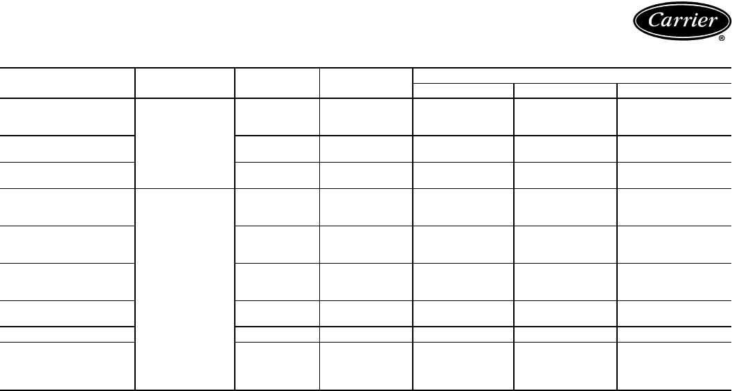
ELECTRIC HEATER
UNIT 88EN
UNIT
50AH
MIN
CFM
UNIT CFM
600 800 1000 1200 1400 1600 1800 2000 2200
0500CA01
024, 036
1-stage
heat
400.02.04.06.10—————
0075CA01510.03.06.10.16—————
0115CA01620 .04.08.13.19—————
0075EA01320
1150EA01720
0100EA01
048, 060
2-stage
heat
970 — — — .04 .06 .08 .12 .15 .17
0150EA011240
0200EA011350 — — — .08 .11 .14 .18 .22 .26
0300EA011220
0300CA011220
0100FA011130 — — — .04 .06 .08 .12 .15 .17
0150FA011360
0200FA011350 — — — .08 .11 .14 .18 .22 .26
0300FA011270
UNIT
50AH
V-PH
(60 Hz)
VOLTAGE RANGE COMPRESSOR FAN MOTORS POWER SUPPLY
Evaporator Condenser Min Ckt
Amps
MOCP
Amps
Min MaxRLA LRA Hp FLA Hp FLA
024 230-1 207 254 11.4 56 .17 1.10 .50 3.40 19.0 25
036
230-1 207 254 17.2 96 .50 3.20 .75 6.06 29.5 40
208/230-3 187 254 10.3 77 .50 3.20 .75 3.93 19.9 25
460-3 414 508 5.1 40 .50 1.50 .75 1.97 8.9 15
048
230-1 207 254 24.4 150 .75 4.00 1.0 8.35 42.9 60
208/230-3 187 254 15.5 105 .75 4.00 1.0 3.93 27.3 35
460-3 414 508 7.4 55 .75 2.15 1.0 1.97 13.4 20
048* 208/230-3 187 254 15.5 105 1.5 5.60 1.0 3.93 28.9 35
460-3 414 508 7.4 55 1.5 2.80 1.0 1.97 16.3 20
060
230-1 207 254 28.8 169 .75 4.00 1.5 9.50 49.5 60
208/230-3 187 254 17.3 123 .75 4.00 1.5 4.82 30.4 40
460-3 414 508 9.0 62 .75 2.15 1.5 2.41 15.8 20
060* 208/230-3 187 254 17.3 123 1.5 5.60 1.5 4.82 32.0 40
460-3 414 508 9.0 62 1.5 2.80 1.5 2.41 16.0 20
HACR — Heating, Air Conditioning, and Refrigeration
Hp — Horsepower
FLA — Full Load Amps
LRA — Locked Rotor Amps
MOCP — Maximum Overcurrent Protection (HACR breaker)
RLA — Rated Load Amps
10
ELECTRIC HEATER DATA
LEGEND
*May be field converted to single-phase units, see electric heat installation instructions.
NOTE: Separate power source is required for all heaters. Control from base unit 50AH (24 v).
ELECTRIC HEATER
UNIT 88EN
USED WITH
UNIT 50AH
V-PH
(60 Hz) CAP. (kW) BRANCH CIRCUIT
Heater Amps MCA MOCP (Amps)
0050CA01
024, 036
1-Stage Heat
240-1 5.0 20.8 26.0 30
0075CA01240-1 7.5 31.3 39.1 40
0115CA01240-1 11.5 47.9 59.9 60
0075EA01208-3 5.6 15.6 19.5 20
240-3 7.6 18.0 22.6 25
1150EA01208-3 11.3 31.2 39.0 40
240-3 15.0 36.1 45.1 50
0100EA01
048, 060
2-Stage Heat
208-3 7.5 20.8 26.0 30
240-1* 10.0 41.7 52.1 60
240-3 10.0 24.1 30.1 35
0150EA01
208-3 11.3 31.2 39.0 40
240-1* 15.0 62.5 78.1 80
240-3 15.0 36.1 45.1 50
0200EA01
208-3 15.0 41.7 52.1 60
240-1* 20.0 83.3 104.2 110
240-3 20.0 46.9 58.6 60
0300EA01208-3 22.5 62.5 78.2 80
240-3 30.0 72.2 90.2 100
0300CA01240-1 30.0 124.0 155.0 175
0100FA01480-3 10.0 12.0 15.0 15
0150FA01480-3 15.0 18.1 22.6 25
0200FA01480-3 20.0 24.1 30.1 35
0300FA01480-3 30.0 36.1 45.1 50
MCA — Minimum Circuit Ampacity
MOCP — Maximum Overcurrent Circuit Protection
(Fuses or Circuit Breaker)
Electrical data (cont)
11
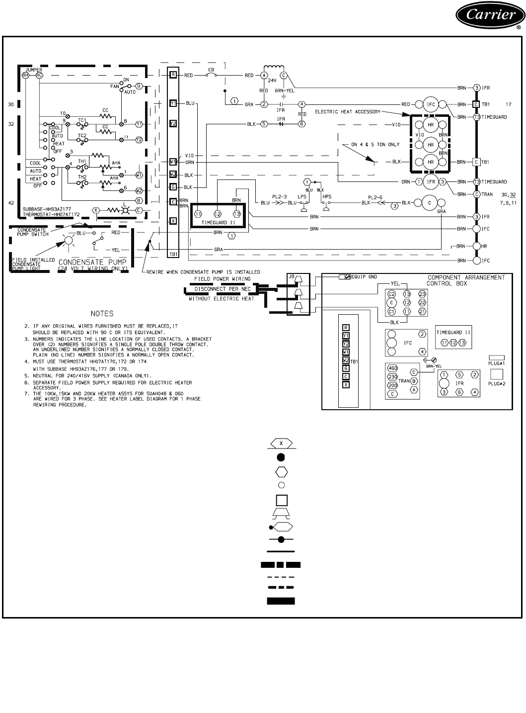
Typical wiring schematic
50AH048,060 — 230-1-60 UNITS
LEGEND
AHA — Adjustable Heat Anticipator
C—Contactor Compressor
CB — Circuit Breaker
CC — Cooling Compensator
EQUIP GND — Equipment Ground
HPS — High-Pressure Switch
HR — Heater Relay
IFC — Indoor (Evaporator) Fan Contactor
IFR — Indoor (Evaporator) Fan Relay
JB—Junction Box
L—Light
LPS — Low-Pressure Switch
NEC — National Electrical Code
PL — Plug Assembly
TB — Terminal Block
TC — Thermostat-Cooling
TH — Thermostat-Heating
TRAN — Transformer
Marked Wire
Denotes connection point between subbase and thermostat
Terminal (Marked)
Terminal (Unmarked)
Terminal Block
Field Splice
Splice (Marked)
Factory Splice
Factory Wiring
Accessory or Optional Wiring
Field Control Wiring
Field Power Wiring
To indicate common potential only not to represent wiring
12
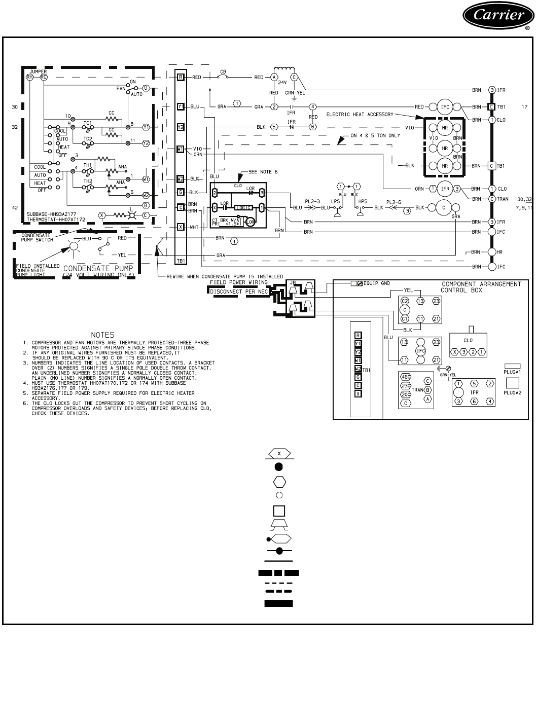
Typical wiring schematic (cont)
50AH036,048,060 — 208/230-3-60 UNITS
LEGEND
AHA — Adjustable Heat Anticipator
C—Contactor Compressor
CB — Circuit Breaker
CC — Cooling Compensator
CLO — Compressor Lockout
CT — Current Transformer
EQUIP GND — Equipment Ground
HPS — High-Pressure Switch
HR — Heater Relay
IFC — Indoor (Evaporator) Fan Contactor
IFR — Indoor (Evaporator) Fan Relay
JB—Junction Box
L—Light
LOR — Lockout Relay
LPS — Low-Pressure Switch
NEC — National Electrical Code
PL — Plug Assembly
TB — Terminal Block
TC — Thermostat-Cooling
TH — Thermostat-Heating
TRAN — Transformer
Marked Wire
Denotes connection point between subbase and thermostat
Terminal (Marked)
Terminal (Unmarked)
Terminal Block
Field Splice
Splice (Marked)
Factory Splice
Factory Wiring
Accessory or Optional Wiring
Field Control Wiring
Field Power Wiring
To indicate common potential only not to represent wiring
13
Application data
OUTDOOR-AIR TEMPERATURE OPERATING LIMITS (F)
Field splitting instructions — If components are split,
maximum length of refrigerant tubing to be used is 50 ft,
assuming components are installed in same horizontal
plane. Condenser may be mounted up to 12 ft above evap-
orator. Liquid line tubing is
3
/
8
-in. OD copper tubing, and
discharge line is
1
/
2
-in. OD copper tubing. For additional
piping information, refer to Carrier System Design Man-
ual, Part 3. Units should always be within line of sight from
each other, or separate NEC (National Electrical Code)
disconnects will be required. Junction boxes should be
installed in both the evaporator and condenser sections
adjacent to D-shaped grommets, to provide a location to
splice the outdoor-fan motor factory wiring (no. 16 AWG
[American Wire Gage],
4
/
64
-in. thick insulation). Field wir-
ing should be a minimum of no. 16 AWG,
4
/
64
-in. thick
insulation. Check all applicable electrical codes to ensure
proper compliance.
UNIT 50AH 024 036 048 060
Without Head Pressure Control Minimum 35 35 40 40
Maximum 126 126 126 126
With Head Pressure Control Minimum 0000
Maximum 126 126 126 126
Typical piping and wiring
LEGEND
NEC — National Electrical Code
NOTES:
1. Wiring and piping shown are not intended for or to include all
details for specific installation.
2. All wiring must comply with applicable local and national codes.
3. All piping must follow standard refrigerant piping techniques. Refer
to Carrier System Design Manual, Part 3, for details.
4. For other installation details refer to Installation Instructions.
5. If unit sections are field split, 8 threaded support rods are required.
6. Ensure condenser air recirculation is minimized.

14
Indoor Packaged Unit
HVAC Guide Specifications — Section 15787
Size Range: 2 to 5 Tons, Nominal
Carrier Model Number: 50AH
Part 1 — General
1.01 SYSTEM DESCRIPTION
Indoor mounted, electrically controlled packaged
horizontal cooling unit utilizing a hermetic type
scroll compressor.
1.02 QUALITY ASSURANCE
A. Unit shall be certified in accordance with ARI
Standard 210.
B. Unit shall be UL listed and carry a UL label.
C. Unit shall be CSA approved (except 3 ton, 3-phase
units).
D. Unit shall be factory run-tested to ensure proper
performance prior to delivery.
1.03 DELIVERY, STORAGE, AND HANDLING
A. Unit shall be shipped completely assembled and
ready to operate.
B. Unit shall be shipped factory charged with refriger-
ant R-22.
C. Unit shall be stored and handled in accordance with
the unit manufacturer’s instructions.
Part 2 — Products
2.01 EQUIPMENT
A. General:
Factory assembled horizontal, single piece, air
cooled, indoor, ceiling plenum mounted electric
cooling unit. Contained within the unit enclosure
shall be all factory wiring, piping, controls, refriger-
ant charge (R-22), and special features required
prior to start-up.
B. Unit Cabinet:
1. Constructed of galvanized steel.
2. Interior shall be insulated with
1
/
2
-in. thick neo-
prene coated fiberglass. Insulation shall be
bonded to interior surfaces by sprayed water
reduceable adhesive.
3. Equipped with 3 same side access panels and
2 bottom hanging removable doors to facilitate
ease of maintenance. Side panels allow access
to the control box, refrigeration components,
and condenser coil. Control box shall be hinged
allowing access to the compressor and pressure
switches. Bottom doors shall allow access to
and easy removal of the condenser and evapo-
rator motors and blower assemblies.
4. Equipped with two
3
/
4
-in. threaded condensate
drain connections below the evaporator coil
and one
3
/
4
-in. threaded connection for con-
denser coil wash down. Connections shall be
factory plugged for field removal.
5. Field splittable through the removal of 4 bolts
and extending refrigerant piping and wiring to
allow remote horizontal or vertical condenser
mounting.
6. Unit shall have an integral hanging bracket
requiring only 4 threaded rods (8 if unit is split)
run to the top flange of the unit for hanging,
eliminating need for external hanger brackets.
7. Contains junction box for power connection
and opening for routing of control wiring.
C. Fans:
1. Evaporator:
a. Blower shall be of the forward-curved, cen-
trifugal, direct-drive type or belt drive (4 and
5 tons only).
b. Motor shall have permanently lubricated
bearings.
c. Unit sizes 048, 060 shall be available with
an optional 1.5 hp fan motor.
2. Condenser:
a. Blower shall be of the forward-curved, cen-
trifugal, direct-driven type (024 only), or belt
drive (036,048,060).
b. Motor shall have permanently lubricated
bearings.
D. Compressor:
1. Fully hermetic scroll type.
2. Mounted on suitable spring vibration isolators.
3. Equipped with internal line break protection.
E. Coils:
Evaporator and condenser coils shall be of non-
ferrous construction with aluminum fins mechani-
cally bonded to seamless copper tubes with all joints
brazed.
F. Refrigerant Components:
Refrigerant components shall include:
1. Capillary tube feed system.
2. Refrigerant filter-drier.
G. Filter Section:
Filter section shall consist of factory-installed, per-
manent, cleanable air filter, removable from the
same side as the access panels without the use of
tools.
H. Controls and Safeties:
Control system shall include a high-pressure switch,
a low-pressure switch, and a compressor lockout
feature which upon tripping of any safety device
shall prevent compressor from restarting until reset
at the thermostat (on all 3-phase units and 036
single-phase units only).
Time Guard®II device (single-phase only) shall pre-
vent the compressor from restarting for a minimum
of 5 minutes after shutdown.
Guide specifications

15
I. Operating characteristics:
1. Unit shall operate using refrigerant R-22.
2. Unit shall be designed for indoor suspended
horizontal mounting and operation.
J. Electrical Requirements
Unit shall have single point power connection to
leads in terminal box.
K. Special Features:
Certain standard features are not applicable when
the features designated by * are specified. For assis-
tance in amending the specifications, your local
Carrier Sales Office should be contacted.
* 1. Electric Heat Module:
a. Provides encased heater elements that shall
attach directly to the base unit discharge.
b. Shall have bottom access.
c. UL listed.
2. Thermostat Assembly:
Provides cooling and fan control. Standard sub-
base shall include ‘‘Compressor malfunction
light’’ designed to illuminate if compressor lock-
out is activated.
3. Time Guard® II Device Compressor Cycle
Delay:
Prevents compressor from restarting for a mini-
mum of 5 minutes after shutdown.
*4.Condensate Pump:
Unit shall be equipped with remotely located
condensate pump. A field-installed light shall
illuminate when reservoir rises above a preset
level. Unit shall shut down upon reservoir light
illumination.
* 5. Head Pressure Control Package:
Allows unit to mechanically cool down to 0° F
ambient temperature. Package shall include
damper operating device and all necessary
hardware.
6. Vibration Isolation Package:
Shall provide 4 spring hangers for ceiling
mounted unit to damper vibration that may be
transmitted to building structure.
Manufacturer reserves the right to discontinue, or change at any time, specifications or designs without notice and without incurring obligations.
New Pg 16 Catalog No. 525-00039 Printed in U.S.A. PC 111 Form 50AH-6PD
Replaces: 50AH-5PD
Book 1 4
Ta b 2 b 7 a
Carrier Corporation • Syracuse, New York 13221 204 9-02
Book 1
Ta b I P 1 a
