Carrier 50He003 006 Users Manual 50h 1si 1 5
50HJ004 to the manual 1b90cbc6-b060-4c64-a7db-f45573cf641f
2015-01-24
: Carrier Carrier-50He003-006-Users-Manual-310406 carrier-50he003-006-users-manual-310406 carrier pdf
Open the PDF directly: View PDF ![]() .
.
Page Count: 72

1
50HJ004---007
50HE003---006
Single---Package Rooftop Electric Cooling
Units with Optional Electric Heat
Installation Instructions
TABLE OF CONTENTS
Page
SAFETY CONSIDERATIONS 1........................
INSTALLATION 1..................................
Step 1--Provide Unit Support 2......................
ROOF CURB 2................................
SLAB MOUNT 2..............................
ALTERNATE UNIT SUPPORT 2.................
Step 2--Field Fabricate Ductwork 2...................
Step 3--Install External Trap for Condensate Drain 2.......
Step 4--Rig and Place Unit 4.........................
POSITIONING 4..............................
Step 5 — Make Electrical Connections 8................
FIELD POWER SUPPLY 8......................
FIELD CONTROL WIRING 8....................
HEAT ANTICIPATOR SETTINGS 8...............
Step 6 — Adjust Factory-Installed Options 29...........
COBRAENERGY RECOVERY UNITS 29.......
HUMIDI-MIZERADAPTIVE
DEHUMIDIFICATION SYSTEM 29..............
DISCONNECT SWITCH 29.....................
MANUAL OUTDOOR-AIR DAMPER 29..........
CONVENIENCE OUTLET 29...................
NOVAR CONTROLS 29........................
PREMIERLINKCONTROL 31.................
OPTIONAL ECONOMI$ER IV AND
ECONOMI$ER2 34............................
ECONOMI$ER IV STANDARD SENSORS 35......
ECONOMI$ER IV CONTROL MODES 36.........
Step 7 — Adjust Evaporator-Fan Speed 41..............
PRE--START--UP 58..................................
START--UP 58.......................................
SERVICE 62........................................
TROUBLESHOOTING 67.............................
START--UP CHECKLIST 72...........................
SAFETY CONSIDERATIONS
Installation and servicing of air-conditioning equipment can be
hazardous due to system pressure and electrical components.
Only trained and qualified service personnel should install, repair,
or service air-conditioning equipment.
Untrained personnel can perform basic maintenance functions of
cleaning coils and filters and replacing filters. All other operations
should be performed by trained service personnel. When working
on air-conditioning equipment, observe precautions in the
literature, tags and labels attached to the unit, and other safety
precautions that may apply.
Follow all safety codes. Wear safety glasses and work gloves. Use
quenching cloth for unbrazing operations. Have fire extinguishers
available for all brazing operations.
Recognize safety information. This is the safety--alert symbol
. When you see this symbol on the furnace and in
instructions or manuals, be alert to the potential for personal
injury.
Understand the signal words DANGER, WARNING, and
CAUTION. These words are used with the safety--alert symbol.
DANGER identifies the most serious hazards which will result in
severe personal injury or death. WARNING signifies a hazard
which could result in personal injury or death. CAUTION is used
to identify unsafe practices which may result in minor personal
injury or product and property damage. NOTE is used to
highlight suggestions which will result in enhanced installation,
reliability,or operation.
ELECTRICAL SHOCK HAZARD
Failure to follow this warning could cause personal
injury or death.
Before performing service or maintenance operations
on unit, turn off main power switch to unit and install
lockout tag. Ensure electrical service to rooftop unit
agrees with voltage and amperage listed on the unit
rating plate.
!WARNING
INSTALLATION
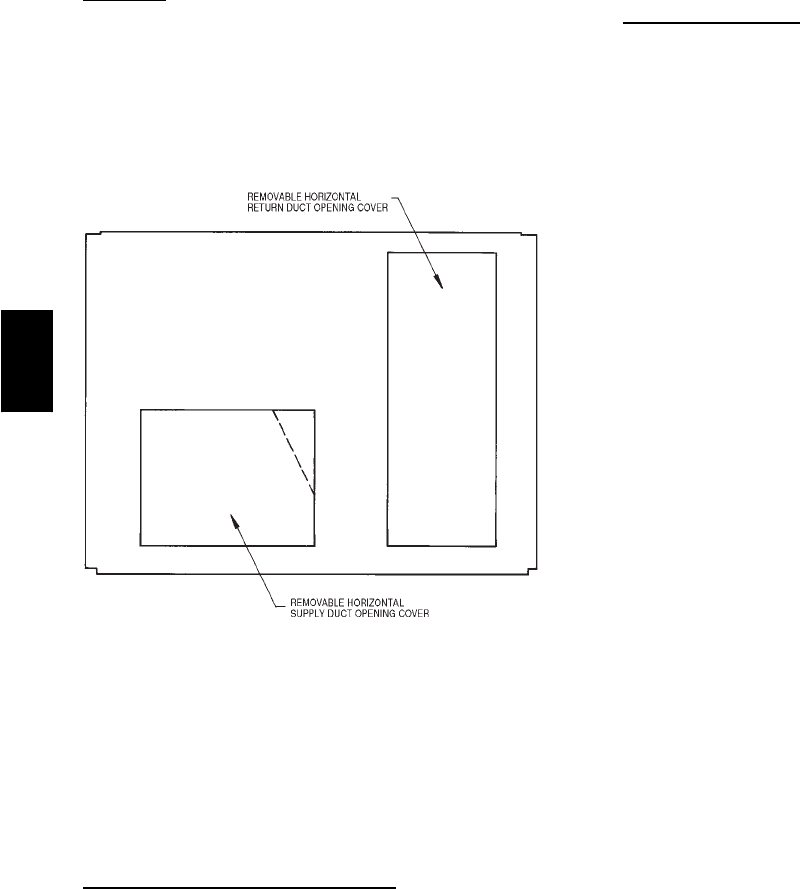
Unit is shipped in the vertical discharge configuration. To convert
to horizontal discharge application, remove duct opening covers.
Using the same screws, install covers on duct openings in
basepan of unit with insulation-side down. Seals around
openings must be tight. (See Fig. 1.)
2
Step 1 —Provide Unit Support
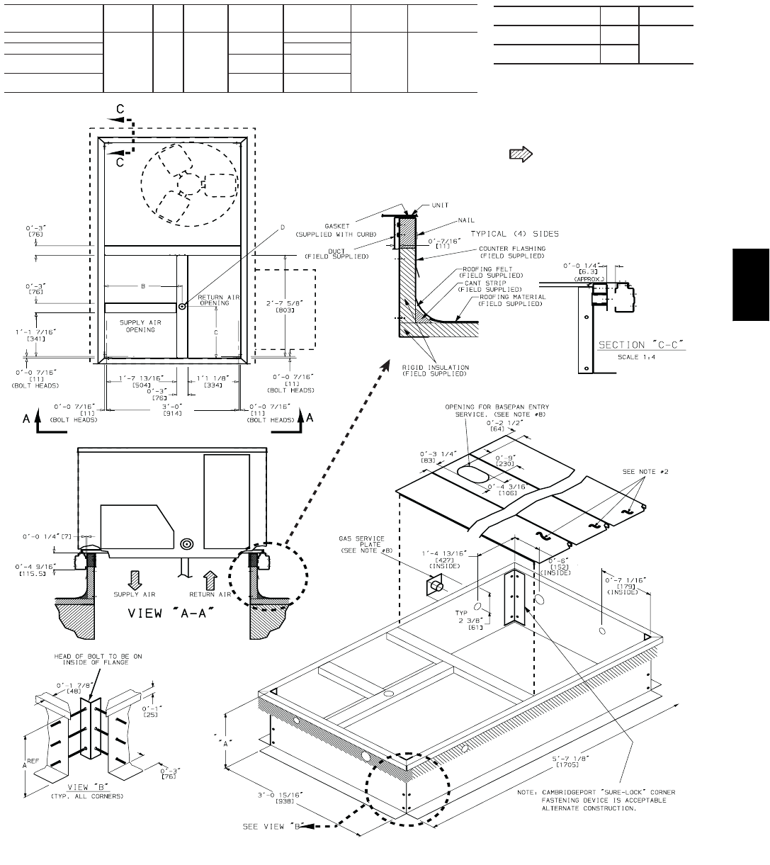
Roof Curb
Assemble and install accessory roof curb in accordance with
instructions shipped with curb. (See Fig. 2.) Install insulation,
cant strips, roofing felt, and counter flashing as shown. Ductwork
must be attached to curb, not to the unit. If electric control power
or gas service is to be routed through the basepan, attach the
accessory thru-the-bottom service connections to the basepan in
accordance with the accessory installation instructions.
Connections must be installed before unit is set on roof curb.
C06108
Fig. 1 --- Horizontal Conversion Panels
IMPORTANT: The gasketing of the unit to the roof curb is critical
for a watertight seal. Install gasket supplied with the roof curb as
shown in Fig. 2. Improperly applied gasket can result in air leaks and
poor unit performance.
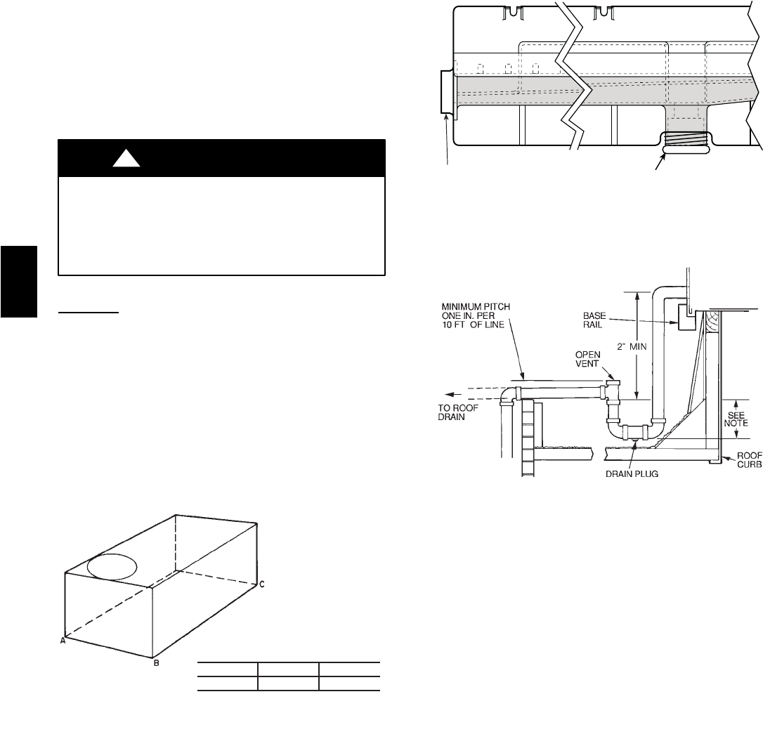
Curb should be level. Unit leveling tolerances are shown in Fig.
3. This is necessary for unit drain to function properly. Refer to
Accessory Roof Curb Installation Instructions for additional
information as required.
Slab Mount (Horizontal Units Only)
Provide a level concrete slab that extends a minimum of 6 in.
beyond unit cabinet. Install a gravel apron in front of
condenser-coil air inlet to prevent grass and foliage from
obstructing airflow.
NOTE: Horizontal units may be installed on a roof curb if
required.
Alternate Unit Support
When the curb or adapter cannot be used, support unit with
sleeper rails using unit curb or adapter support area. If sleeper
rails cannot be used, support the long sides of the unit with a
minimum of 3 equally spaced 4-in. x 4-in. pads on each side.
Step 2 —Field Fabricate Ductwork
Secure all ducts to roof curb and building structure on vertical
discharge units. Do not connect ductwork to unit. For horizontal
applications, field-supplied isolation flanges should be attached to
horizontal discharge openings and all ductwork should be secured
to the flanges. Insulate and weatherproof all external ductwork,
joints, and roof openings with counter flashing and mastic in
accordance with applicable codes.
Ducts passing through an unconditioned space must be insulated
and covered with a vapor barrier.
If a plenum return is used on a vertical unit, the return should be
ducted through the roof deck to comply with applicable fire
codes.
A minimum clearance is not required around ductwork. Cabinet
return-air static pressure (a negative condition) shall not exceed
0.35 in. wg with economizer or 0.45 in. wg without economizer.
Step 3 —Install External Trap for
Condensate Drain
Condensate drain connections are located on the bottom and side
of the unit. Unit discharge connections do not determine the use
of drain connections; either drain connection can be used with
vertical or horizontal applications.
When using the standard side drain connection, ensure the plug
(Red) in the alternate bottom connection is tight before installing
the unit.
To use the bottom drain connection for a roof curb installation,
relocate the factory-installed plug (Red) from the bottom
connection to the side connection. The center drain plug looks
like a star connection, however it can be removed with a 1/2-in.
socket drive extension. (See Fig. 4.) The piping for the
condensate drain and external trap can be completed after the unit
is in place.
All units must have an external trap for condensate drainage.
Install a trap 4-in. deep and protect against freeze-up. If drain line
is installed downstream from the external trap, pitch the line away
from the unit at 1 in. per 10 ft of run. Do not use a pipe size
smaller than the unit connection (3/4in.). (See Fig. 5.)
50HE,HJ
3
ROOF CURB
ACCESSORY AUNIT
SIZE
CRRFCURB001A01 1-2
[356]
CRRFCURB002A01 2-0
[610]
NOTES:
1. Roof curb accessory is shipped disassembled.
2. Insulated panels.
3. Dimensions in [ ] are in millimeters.
4. Roof curb: galvanized steel.
5. Attach ductwork to curb (flanges of duct rest
on curb).
6. Service clearance: 4 ft on each side.
7. Direction of airflow.
8. Connector packages CRBTMPWR001A01
and 002A01 are for thru-the-curb type gas.
Packages CRBTMPWR003A01 and 004A01
are for thru-the-bottom type gas connections.
CONNECTOR
PKG. ACCY. BC
DALT
DRAIN
HOLE
GAS POWER CONTROL ACCESSORY
POWER
CRBTMPWR001A01
1-9
11
/
16
[551] 1-4
[406] 1
3
/
4
[44.5]
3
/
4
[19] NPT
3
/
4
[19] NPT
1
/
2
[12.7]
1
/
2
[12.7]
CRBTMPWR002A01 1
1
/
4
[31.7]
CRBTMPWR003A01
1
/
2
[12.7] NPT
3
/
4
[19] NPT
CRBTMPWR004A01
3
/
4
[19] NPT 1
1
/
4
[31.7]
50HJ004-007
50HE003-006
C06155
Fig. 2 --- Roof Curb Details
50HE,HJ
4
Step 4 —Rig and Place Unit
Inspect unit for transportation damage, and file any claim with
transportation agency. Keep unit upright and do not drop.
Spreader bars are not required if top crating is left on unit, and
rollers may be used to move unit across a roof. Level by using
unit frame as a reference. See Table 1, 2 and Fig. 6 for additional
information. Operating weight is shown in Table 1, 2 and Fig. 6.
Lifting holes are provided in base rails as shown in Fig. 7. Refer
to rigging instructions on unit.
PERSONAL INJURY AND PROPERTY DAMAGE
HAZARD
Failure to follow this warning could result in personal
injury, death and property damage.
All panels must be in place when rigging and lifting.
!WARNING
Positioning
Maintain clearance around and above unit to provide minimum
distance from combustible materials, proper airflow, and service
access. (See Fig. 7, 8 and 9.)
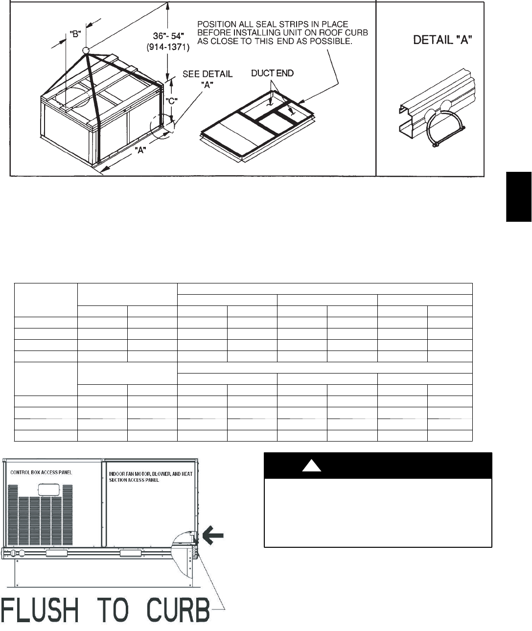
Position unit on roof curb so that the following clearances are
maintained: 1/4in. clearance between the roof curb and the base
rail inside the front and rear, 0.0 in. clearance between the roof
curb and the base rail inside on the duct end of the unit. This will
result in the distance between the roof curb and the base rail
inside on the condenser end of the unit being approximately
equal to Fig. 2, section C-C.
Do not install unit in an indoor location. Do not locate unit air
inlets near exhaust vents or other sources of contaminated air.
MAXIMUM ALLOWABLE
DIFFERENCE (in.)
A-B B-C A-C
0.5 1.0 1.0
C06110
Fig. 3 --- Unit Leveling Tolerances
DRAIN PLUG
CONDENSATE PAN (SIDE VIEW)
HORIZONTAL
DRAIN OUTLET
NOTE: Drain plug is shown in factory-installed position.
C06003
Fig. 4 --- Condensate Drain Connection
NOTE: Trap should be deep enough to offset maximum unit static
difference. A 4-in. trap is recommended.
C06004
Fig. 5 --- Condensate Drain Piping Details
Although unit is weatherproof, guard against water from higher
level runoff and overhangs.
After unit is in position, remove polyethylene shipping wrapper
and top crating.
50HE,HJ
5
NOTES:
1. Place unit on curb as close as possible to the duct end.
2. Dimension in ( ) is in millimeters.
3. Hook rigging shackles through holes in base rail as shown in detail "A." Holes in base rails are centered around the unit center of gravity. Use wooden
top skid when rigging to prevent rigging straps from damaging unit.
4. Weights include base unit without economizer. See Table 1 for unit operating weights with accessory economizer.
5. Weights include base unit without the Humidi-MiZerTM adaptive dehumidification system. See Table 1 for unit operating weights with the
Humidi-MiZer system.
C06111
Fig. 6 --- Rigging Details
UNIT
50HE
OPERATING
WEIGHT
DIMENSIONS
“A” “B” “C”
lb kg in. mm in. mm in. mm
003 435 197 73.69 1872 35.50 902 33.31 847
004 445 202 73.69 1872 35.50 902 33.31 847
005 465 211 73.69 1872 35.50 902 33.31 847
006 520 236 73.69 1872 35.50 902 33.31 847
UNIT
50HJ
OPERATING
WEIGHT
DIMENSIONS
“A” “B” “C”
lb kg in. mm in. mm in. mm
004 530 240 73.69 1872 35.50 902 33.31 847
005 540 245 73.69 1872 35.50 902 33.31 847
006 560 254 73.69 1872 35.50 902 33.31 847
007 635 288 73.69 1872 35.50 902 33.31 847
C06208
Fig. 7 --- Roof Curb Alignment
PERSONAL INJURY AND PROPERTY DAMAGE
HAZARD
Failure to follow this warning could result in personal
injury, death and property damage.
All panels must be in place when rigging and lifting.
!WARNING
50HE,HJ
6
C06156
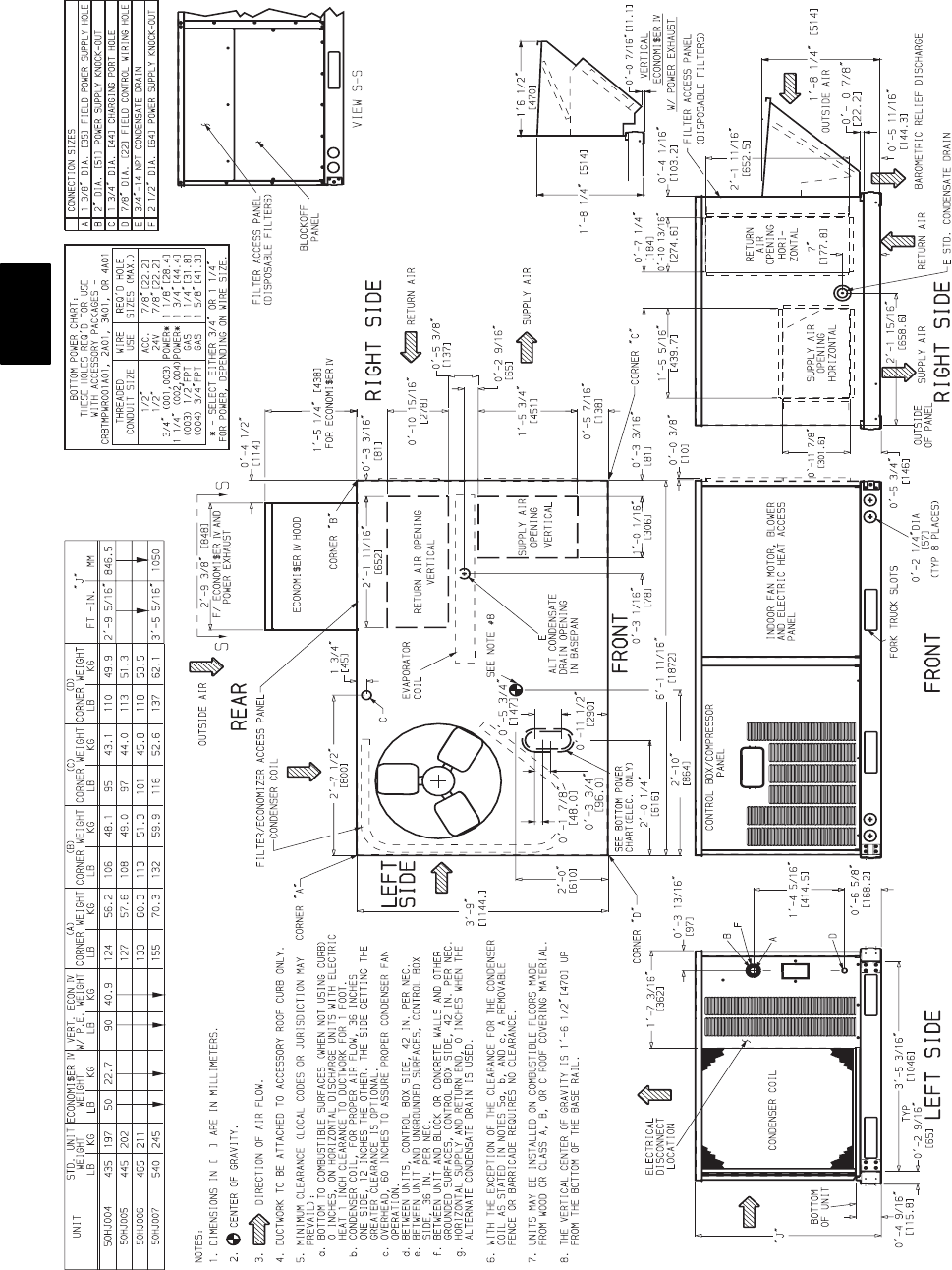
Fig. 8 --- 50HJ004--007 Base Unit Dimensions
50HE,HJ
7
C06157
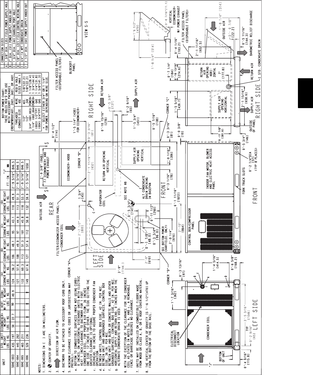
Fig. 9 --- 50HE003--006 Base Unit Dimensions
50HE,HJ
8
Step 5 —Make Electrical Connections
ELECTRICAL SHOCK HAZARD
Failure to follow this warning could result in personal
injury or death,
Unit cabinet must have an uninterrupted, unbroken
electrical ground to minimize the possibility of personal
injury if an electrical fault should occur. This ground may
consist of electrical wire connected to unit ground lug in
control compartment, or conduit approved for electrical
ground when installed in accordance with NEC (National
Electrical Code), ANSI/NFPA (National Fire Protection
Association), latest edition, and local electrical codes. Do
not use gas piping as an electrical ground.
!WARNING
Field Power Supply
All units except 208/230-v units are factory wired for the voltage
shown on the nameplate. If the 208/230-v unit is to be connected
to a 208-v power supply, the transformer must be rewired by
disconnecting the black wire from the 230-v 1/4--in. terminal on
the transformer and connecting it to the 200-v 1/4--in. terminal
from the transformer.
Refer to unit label diagram for additional information. Pigtails
are provided for field service. Use factory-supplied splices or UL
(Underwriters’ Laboratories) approved copper connector.
When installing units, provide a disconnect per NEC.
All field wiring must comply with NEC and local
requirements.
Install field wiring as follows:
1. Install conduit through side panel openings. For units
without electric heat, install conduit between disconnect
and control box.
2. Install power lines to terminal connections as shown in
Fig. 12.
3. For units with electric heat, refer to Accessory Electric
Heat Installation Instructions.
During operation, voltage to compressor terminals must bewithin
range indicated on unit nameplate (also see Table 3 and 4). On
3--phase units, voltages between phases must be balanced within
2% and the current within 10%. Use the formula shown in Table
3 and 4, Note 2, to determine the percentage of voltage
imbalance. Operation on improper line voltage or excessive phase
imbalance constitutes abuse and may cause damage to electrical
components. Such operation invalidates any applicable Carrier
warranty.
NOTE: If accessory thru-the-bottom connections and roof curb
are used, refer to the Thru-the-Bottom Accessory Installation
Instructions for information on wiring the unit.
Field Control Wiring
Install a Carrier-approved accessory thermostat assembly
according to installation instructions included with the accessory.
Locate thermostat assembly on a solid wall in the conditioned
space to sense average temperature in accordance with thermostat
installation instructions.
Route thermostat cable or equivalent single leads of colored wire
from subbase terminals through connector on unit to low-voltage
connections (shown in Fig. 10 and 11).
NOTE: For wire runs up to 50 ft, use no. 18 AWG (American
Wire Gauge) insulated wire (35_Cminimum).For50to75ft,use
no. 16 AWG insulated wire (35_C minimum). For over 75 ft, use
no. 14 AWG insulated wire (35_C minimum). All wire larger
than no. 18 AWG cannot be directly connected to the thermostat
and will require a junction box and splice at the thermostat.
1. Connect thermostat wires to screw terminals of lowvoltage
terminal board.
2. Pass the control wires through the hole provided in the
control box.
3. Some models may be equipped with a raceway built into
the corner post on the left side of control box (See Fig.
13.) This raceway provides the required clearance between
high--voltage and low voltage wiring. For models without
a raceway, ensure to provide the NEC required clearance
between high--voltage and low--voltage wiring.
Heat Anticipator Settings
Set heat anticipator settings at 0.8 amp for first stage and 0.3 for
second stage heating.
WIRE
CONNECTIONS
TO
LOW-VOLTAGE
SECTION
COOL STAGE 1
FAN
HEAT STAGE 1
COOL STAGE 2
HEAT STAGE 2
24 VAC HOT
24 VAC COM
N/A
OUTDOOR AIR
SENSOR
Y1/W2
G
W/W1
Y/Y2
O/W2
R
C
S1
S2
THERMOSTAT DIPSWITCH SETTINGS
R
G
Y1
Y2
W1
W2
C
IPD/X
ON
OFF
ABCD
LEGEND
NOTE: Underlined letter indicates active thermostat output when
configured for A/C operation.
Field Wiring
C06008
Fig. 10 --- Low--Voltage connections With or
Without Economizer or Two--Position Damper
W2
C
Y1
G
R
Y2
W1
C
G
R
Y2
W1
X
W2
C
Y1
G
R
Y2
W1
X
24 VAC
RMTOCC
CMPSAFE
FSD
NOT USED
C
X
SFS
THERMOSTAT CONTROL
CONNECTION
BOARD
BOARD
CONNECTION
CONTROL
C06009
Fig. 11 --- Low--Voltage Connections
(Units with PremierLinktControls)
50HE,HJ

9
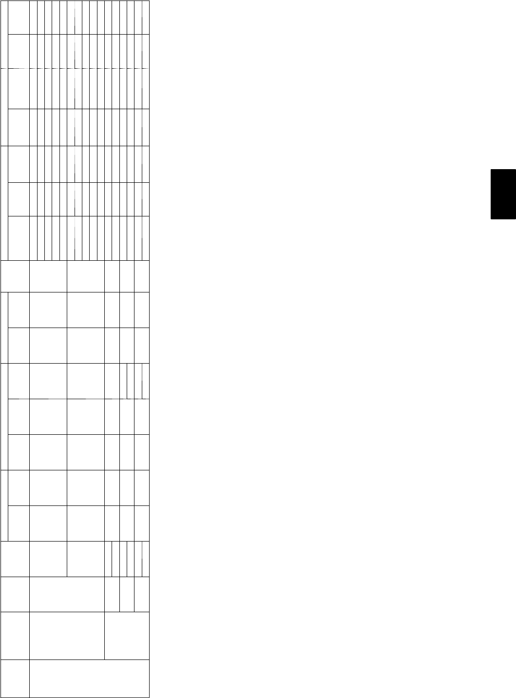
Table 1—Physical Data 50HJ
BASE UNIT 50HJ 004 005 006 007
NOMINAL CAPACITY 3 4 5 6
OPERATING WEIGHT (lb)
Unit 435 445 465 540
Humidi-MiZerAdaptive Dehumidification System 15 23 25 29
EconoMi$er IV 50 50 50 50
Roof Curb 115 115 115 115
COMPRESSOR Scroll
Quantity 1 1 1 1
Oil (oz) 42 53 50 60
REFRIGERANT TYPE R-22
Expansion Device AcutrolMetering Device
Operating Charge (lb-oz)
Standard Unit 5-8 10-2 10-0 12- 8
Unit With Humidi-Mizer Adaptive Dehumidification System 12-5 18-8 20-5 23-14
CONDENSER FAN Propeller
Quantity...Diameter (in.) 1...22 1...22 1...22 1...22
Nominal Cfm 3500 3500 4100 4100
Motor Hp...Rpm 1/8...825 1/8...825 1/4...1100 1/4...1100
Watts Input (Total) 180 180 320 320
CONDENSER COIL Enhanced Copper Tubes, Aluminum Lanced Fins
Rows...Fins/in. 1...17 2...17 2...17 2...17
Total Face Area (sq ft) 14.6 16.5 16.5 21.3
EVAPORATOR COIL Enhanced Copper Tubes, Aluminum Double-Wavy Fins
Standard Unit
Rows...Fins/in. 2...15 2...15 4...15 4...15
Total Face Area (sq ft) 5.5 5.5 5.5 7.3
Unit with Humidi-Mizer Adaptive Dehumidification System
Rows...Fins/in. 1...17 2...17 2...17 2...17
Total Face Area (sq ft) 3.9 3.9 3.9 5.2
EVAPORATOR FAN Centrifugal Type, Belt Drive
Quantity...Size (in.) 1...10 x 10 1...10 x 10 1...10 x 10 1...10 x 10
Nominal Cfm 1200 1600 2000 2400
Maximum Continuous Bhp Std 1.20 1.20 1.30/2.40* 2.40
Hi-Static 2.40 2.40 2.90 2.90
Motor Frame Size Std 48 48 56 56
Hi-Static 56 56 56 56
Fan Rpm Range Std 680-1044 770-1185 1035-1460/1035---1460* 1120-1585
Hi-Static 1075-1455 1075-1455 1300-1685 1300-1685
Motor Bearing Type Ball Ball Ball Ball
Maximum Fan Rpm 2100 2100 2100 2100
Motor Pulley Pitch Diameter A/B (in.) Std 1.9/2.9 1.9/2.9 2.4/3.4 2.4/3.4
Hi-Static 2.8/3.8 2.8/3.8 3.4/4.4 3.4/3.4
Nominal Motor Shaft Diameter (in.) Std 1/21/25/85/8
Hi-Static 5/85/87/87/8
Fan Pulley Pitch Diameter (in.) Std 4.5 4.0 4.0 3.7
Hi-Static 4.5 4.5 4.5 4.5
Belt — Type...Length (in.) Std 1...A...36 1...A...36 1....4...40 1...A...38
Hi-Static 1...A...39 1...A...39 1...A...40 1...A...40
Pulley Center Line Distance (in.) 10.0-12.4 10.0-12.4 14.7-15.5 14.7-15.5
Speed Change per Full Turn of
Movable Pulley Flange (rpm)
Std 65 70 75 95
Hi-Static 65 65 60 60
Movable Pulley Maximum Full
Turns from Closed Position
Std 55 6 5
Hi-Static 66 5 5
Factory Setting — Full Turns Open Std 33 3 3
Hi-Static 31/231/231/231/2
Factory Speed Setting (rpm) Std 826 936 1248 1304
Hi-Static 1233 1233 1396 1396
Fan Shaft Diameter at Pulley (in.) 5/85/85/85/8
HIGH-PRESSURE SWITCH (psig)
Standard Compressor Internal Relief 450 50
Cutout 428
Reset (Auto.) 320
LOSS-OF-CHARGE/LOW-PRESSURE
SWITCH (Liquid LIne) (psig)
Cutout 73
Reset (Auto.) 22 5
FREEZE PROTECTION THERMOSTAT
Opens (F) 30
Closes (F) 45
OUTDOOR-AIR INLET SCREENS Cleanable. Screen quantity and size varies with option selected.
RETURN-AIR FILTERS Throwaway
Quantity...Size (in.) 2...16 x 25 x 2 2...16 x 16 x 2
LEGEND
Bhp — Brake Horsepower
*Single phase/three phase.
50HE,HJ

10
Table 2—Physical Data 50HE
BASE UNIT 50HE 003 004 005 006
NOMINAL CAPACITY 2 3 4 5
OPERATING WEIGHT (lb)
Unit 435 445 465 635
Humidi-MiZerAdaptive Dehumidification System 13 15 23 25
EconoMi$er IV 50 50 50 50
Roof Curb 115 115 115 115
COMPRESSOR Scroll
Quantity 1 1 1 1
Oil (oz) 25 42 56 53
REFRIGERANT TYPE R-22
Expansion Device AcutrolMetering Device
Operating Charge (lb-oz)
Standard Unit 5 --- 3 7 --- 1 1 8 --- 8 12---11
Unit With Humidi-Mizer Adaptive Dehumidification System 1 0 --- 2 1 4 --- 0 14---13 2 1 --- 0
CONDENSER FAN Propeller
Quantity...Diameter (in.) 1...22 1...22 1...22 1...22
Nominal Cfm 3000 3500 3500 4100
Motor Hp...Rpm 1/8...825 1/8...825 1/8...825 1/4...1100
Watts Input (Total) 180 180 180 320
CONDENSER COIL Enhanced Copper Tubes, Aluminum Lanced Fins
Rows...Fins/in. 1...17 1...17 2...17 2...17
Total Face Area (sq ft) 14.6 14.6 16.5 16.5
EVAPORATOR COIL Enhanced Copper Tubes, Aluminum Double-Wavy Fins
Standard Unit
Rows...Fins/in. 2...15 2...15 2...15 4...15
Total Face Area (sq ft) 4.2 5.5 5.5 5.5
Unit with Humidi-Mizer Adaptive Dehumidification System
Rows...Fins/in. 1...17 1...17 2...17 2...17
Total Face Area (sq ft) 3.5 3.9 3.9 3.9
EVAPORATOR FAN Centrifugal Type, Belt Drive
Quantity...Size (in.) 1...10 x 10 1...10 x 10 1...10 x 10 1...10 x 10
Nominal Cfm 800 1200 1600 2000
Maximum Continuous Bhp Std 0.58 1.20 1.20 1.30/2.40*
Hi-Static 2.40 2.40 2.90
Motor Frame Size Std 48 48 48 48/56*
Hi-Static 56 56 56
Motor Rpm 1620 1620 1620 1725
Fan Rpm Range Std 400-1000 680-1044 770-1185 1035-1460
Hi-Static 1075-1455 1075-1455 1300-1685
Motor Bearing Type Ball Ball Ball Ball
Maximum Fan Rpm 1620 2100 2100 2100
Motor Pulley Pitch Diameter A/B (in.) Std 2.4/3.2 1.9/2.9 1.9/2.0 2.4/3.4
Hi-Static 2.8/3.8 2.8/3.8 3.4/4.4
Nominal Motor Shaft Diameter (in.) Std 5/81/21/25/8
Hi-Static 7/85/85/85/8
Fan Pulley Pitch Diameter (in.) Std 4.0 4.5 4.0 4.0
Hi-Static 4.5 4.5 4.0 4.5
Belt — Type...Length (in.) Std 1...A...36 1...A...36 1...A...36 1....4...40
Hi-Static 1...A...39 1...A...39 1...A...40
Pulley Center Line Distance (in.) 10.0---12.4 10.0-12.4 10.0-12.4 14.7-15.5
Speed Change per Full Turn of
Movable Pulley Flange (rpm)
Std 60 65 70 75
Hi-Static 65 65 60
Movable Pulley Maximum Full
Turns from Closed Position
Std 55 5 6
Hi-Static 6 6 5
Factory Setting — Full Turns Open Std 33 3 3
Hi-Static 31/231/231/2
Factory Speed Setting (rpm) Std 756 826 936 1248
Hi-Static 1233 1233 1396
Fan Shaft Diameter at Pulley (in.) 5/85/85/85/8
HIGH-PRESSURE SWITCH (psig)
Standard Compressor Internal Relief 450 50
Cutout 428
Reset (Auto.) 320
LOSS-OF-CHARGE/LOW-PRESSURE
SWITCH (Liquid LIne) (psig)
Cutout 73
Reset (Auto.) 22 5
FREEZE PROTECTION THERMOSTAT
Opens (F) 30
Closes (F) 45
OUTDOOR-AIR INLET SCREENS Cleanable. Screen quantity and size varies with option selected.
RETURN-AIR FILTERS Throwaway
Quantity...Size (in.) 2...16 x 25 x 2
LEGEND
Bhp — Brake Horsepower
*Single phase/three phase.
***These units do NOT meet the California low NOx requirements.
†††California SCAQMD compliant low NOxmodels have combustion products that are
controlled to 40 nanograms per joule or less.
50HE,HJ
11
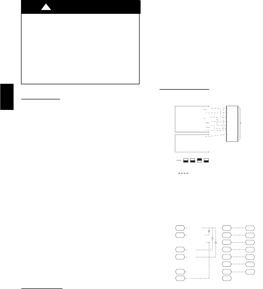
LEGEND
C—Contactor
COMP — Compressor
IFC — Indoor (Evaporator) Fan Contactor
NEC — National Electrical Code
TB — Terminal Block
208/230-1-60
575-3-60
(SIZES 006 AND 007)
208/230-3-60
(SIZES 004 AND 005)
208/230-3-60
460-3-60
(SIZES 006 AND 007)
575-3-60
(SIZES 004 AND 005)
460-3-60
(SIZES 004 AND 005)
C06158
Fig. 12 --- Power Wiring Connections
LOW VOLTAGE
CONNECTIONS INTEGRATED GAS UNIT
CONTROLLER (IGC)
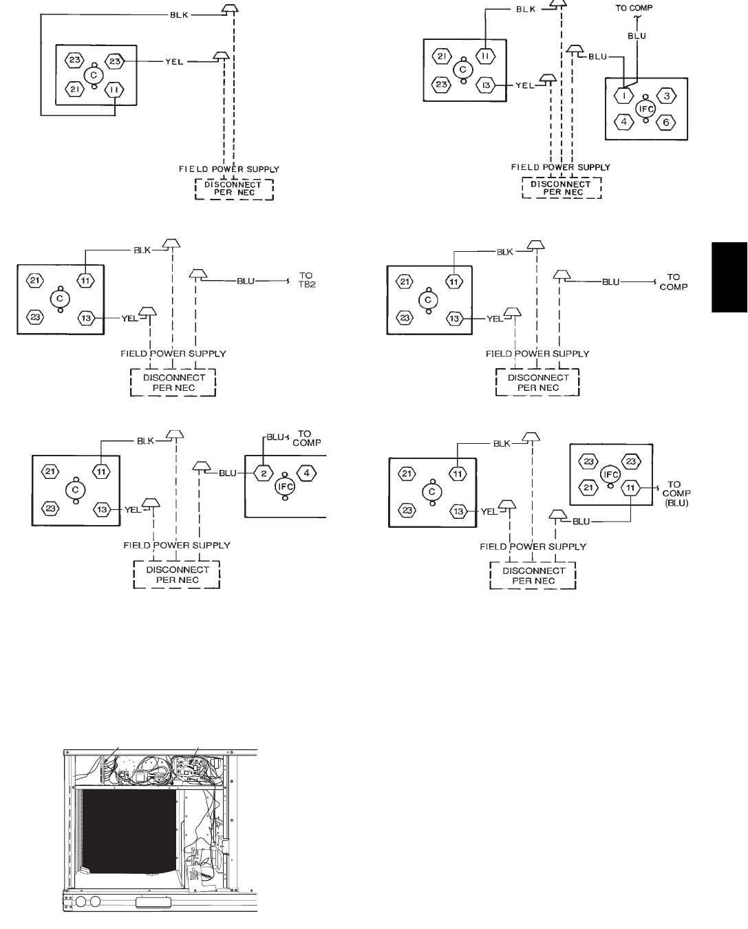
C06125
Fig. 13 --- Field Control Wiring Raceway
50HE,HJ

12
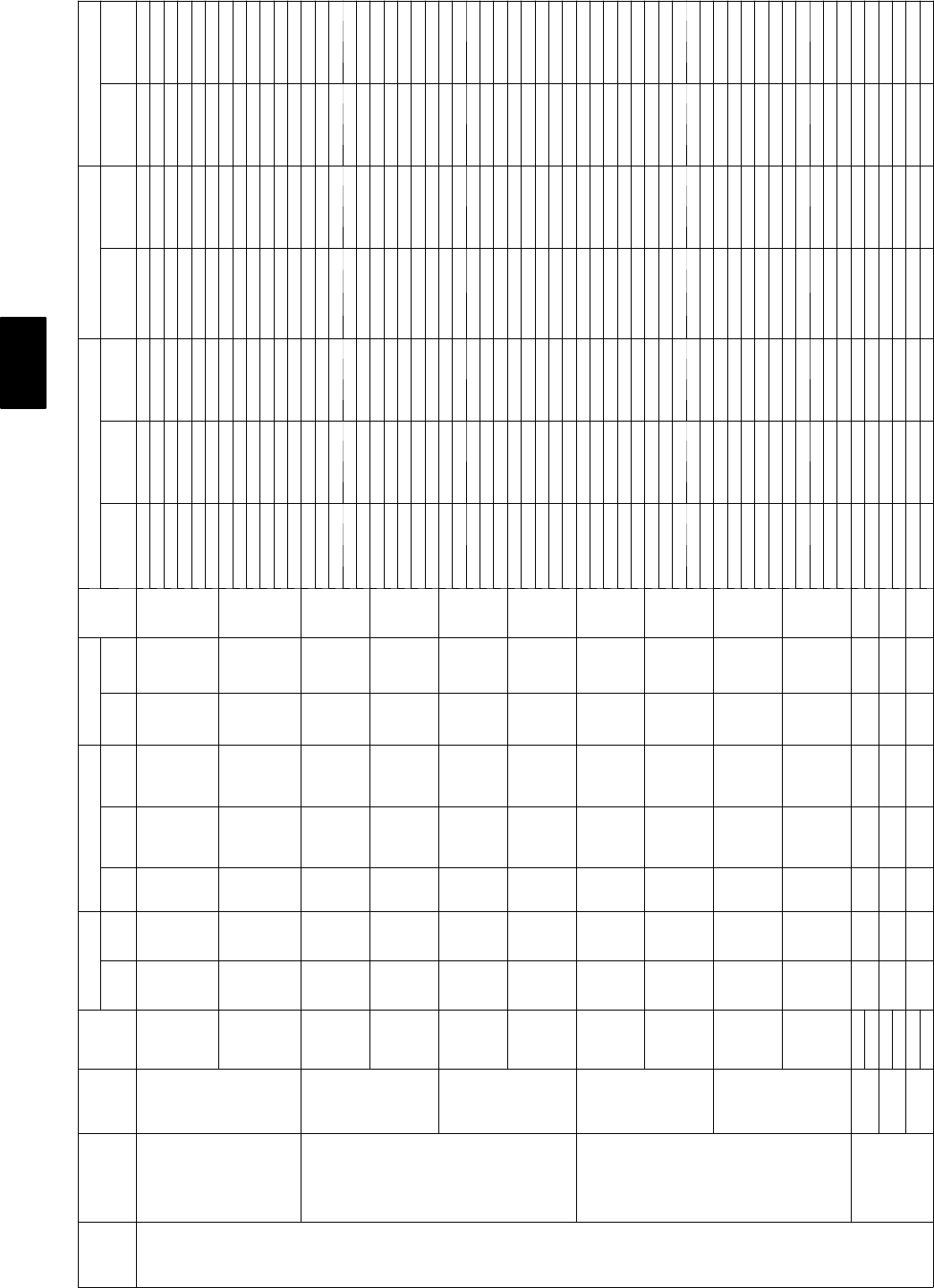
Table 3—Electrical Data--50HE
UNIT SIZE Nominal
V --- P h --- H z IFM
TYPE
CONV
OUTLET
VOLTAGE RANGE COMPRESSOR (each) OUTDOOR FAN
IFM
FLA
ELECTRIC HEAT POWER SUPPLY * DISCONNECT SIZE
Min Max QTY RLA LRA QTY FLA
CRHEATER
--- --- --- A 0 0
or B00
Actual
kW†
FLA MCA MOCP** FLA LRA
003
(2 tons) 208/230--- 1--- 60 STD
NO 187 254 110.9 63.0 10.7 2.0
NONE —/ — —/— 16.3/16.3 20/20 16/16 69/69
001A00 3.3/ 4.0 15.9/18.3 22.4/25.4 25/30 21/23 69/69
002A00 4.9/ 5.8 23.5/27.1 31.8/36.4 35/40 29/33 69/69
003B00 6.5/ 8.0 31.4/36.3 41.8/47.8 45/50 38/44 69/69
004B00 7.9/ 9.6 37.9/43.8 49.9/57.2 50/60 46/53 69/69
YES 187 254 110.9 63.0 10.7 2.0
NONE —/ — —/— 22.3/22.3 25/25 21/21 73/73
001A00 3.3/ 4.0 15.9/18.3 27.4/30.4 30/35 26/29 73/73
002A00 4.9/ 5.8 23.5/27.1 36.8/41.4 40/45 35/39 73/73
003B00 6.5/ 8.0 31.4/36.3 46.8/52.8 50/60 44/50 73/73
004B00 7.9/ 9.6 37.9/43.8 54.9/62.2 60/70 51/58 73/73
004
(3 tons)
208/230--- 1--- 60 STD
NO 187 254 116.0 88.0 10.7 4.9
NONE —/ — —/— 25.6/25.6 30/30 25/25 101/101
001A00 3.3/ 4.0 15.9/18.3 26.0/29.0 30/30 25/27 101/101
002A00 4.9/ 5.8 23.5/27.1 35.5/40.0 40/40 33/37 101/101
003B00 6.5/ 8.0 31.4/36.3 45.4/51.4 50/60 42/47 101/101
004B00 7.9/ 9.6 37.9/43.8 53.5/60.8 60/70 49/56 101/101
002,002 9.8/11.6 46.9/54.2 64.8/73.8 70/80 60/68 101/101
YES 187 254 116.0 88.0 10.7 4.9
NONE —/ — —/— 31.6/31.6 35/35 30/30 106/106
001A00 3.3/ 4.0 15.9/18.3 31.6/34.0 35/35 30/32 106/106
002A00 4.9/ 5.8 23.5/27.1 40.5/45.0 45/45 38/42 106/106
003B00 6.5/ 8.0 31.4/36.3 50.4/56.4 60/60 47/53 106/106
004B00 7.9/ 9.6 37.9/43.8 58.5/65.8 60/70 55/61 106/106
002,002 9.8/11.6 46.9/54.2 69.8/78.8 70/80 65/73 106/106
208/230--- 3--- 60
STD
NO 187 254 110.3 77.0 10.7 4.9
NONE —/ — —/— 18.5/18.5 25/25 18/18 90/90
001A00 3.3/ 4.0 9.2/10.6 18.5/19.4 25/25 18/18 90/90
002A00 4.9/ 5.8 13.6/15.6 23.1/25.7 25/30 21/24 90/90
003B00 6.5/ 8.0 18.1/20.9 28.8/32.3 30/35 26/30 90/90
004B00 7.9/ 9.6 21.9/25.3 33.5/37.7 35/40 31/35 90/90
005A00 12/14.7 33.4/38.5 47.8/54.2 50/60 44/50 90/90
YES 187 254 110.3 77.0 10.7 4.9
NONE —/ — —/— 24.5/24.5 30/30 24/24 95/95
001A00 3.3/ 4.0 9.2/10.6 24.5/24.5 30/30 24/24 95/95
002A00 4.9/ 5.8 13.6/15.6 28.1/30.7 30/35 27/29 95/95
003B00 6.5/ 8.0 18.1/20.9 33.8/37.3 35/40 32/35 95/95
004B00 7.9/ 9.6 21.9/25.3 38.5/42.7 40/45 36/40 95/95
005A00 12/14.7 33.4/38.5 52.8/59.2 60/60 50/55 95/95
HS
NO 187 254 110.3 77.0 10.7 5.8
NONE —/ — —/— 19.4/19.4 25/25 19/19 120/120
001A00 3.3/ 4.0 9.2/10.6 19.4/20.5 25/25 19/19 120/120
002A00 4.9/ 5.8 13.6/15.6 24.2/26.8 30/30 22/25 120/120
003B00 6.5/ 8.0 18.1/20.9 29.9/33.4 35/35 28/31 120/120
004B00 7.9/ 9.6 21.9/25.3 34.6/38.8 35/40 32/36 120/120
005A00 12/14.7 33.4/38.5 48.9/55.4 50/60 45/51 120/120
YES 187 254 110.3 77.0 10.7 5.8
NONE —/ — —/— 25.4/25.4 30/30 25/25 124/124
001A00 3.3/ 4.0 9.2/10.6 25.4/25.5 30/30 25/25 124/124
002A00 4.9/ 5.8 13.6/15.6 29.2/31.8 35/35 28/30 124/124
003B00 6.5/ 8.0 18.1/20.9 34.9/38.4 40/40 33/36 124/124
004B00 7.9/ 9.6 21.9/25.3 39.6/43.8 40/45 37/41 124/124
005A00 12/14.7 33.4/38.5 53.9/60.4 60/70 51/56 124/124
4 6 0 --- 3 --- 6 0 STD
NO 414 508 15.1 39.0 10.4 2.2
NONE — — 9.0 15.0 9.0 46.0
006A00 5.5 7.2 11.8 15.0 11.0 46.0
007A00 8.1 10.6 16.0 20.0 15.0 46.0
008A00 10.6 13.8 20.0 25.0 18.0 46.0
009A00 12.9 16.8 23.8 25.0 22.0 46.0
YES 414 508 15.1 39.0 10.4 2.2
NONE — — 11.7 15.0 11.0 48.0
006A00 5.5 7.2 15.1 20.0 13.0 48.0
007A00 8.1 10.6 19.4 20.0 17.0 48.0
008A00 10.6 13.8 23.4 25.0 21.0 48.0
009A00 12.9 16.8 27.2 30.0 24.0 48.0
50HE,HJ
13
Table 3 — Electrical Data--50HE (cont)
UNIT SIZE Nominal
V --- P h --- H z IFM
TYPE
CONV
OUTLET
VOLTAGE RANGE COMPRESSOR (each) OUTDOOR FAN
IFM
FLA
ELECTRIC HEAT POWER SUPPLY * DISCONNECT SIZE
Min Max QTY RLA LRA QTY FLA
CRHEATER
--- --- --- A 0 0
or B00
Actual
kW†
FLA MCA MOCP** FLA LRA
004
(3 tons)
4 6 0 --- 3 --- 6 0 HS
NO 414 508 15.1 39.0 10.4 2.6
NONE — — 9.4 15.0 9.0 60.0
006A00 5.5 7.2 12.3 15.0 11.0 60.0
007A00 8.1 10.6 16.5 20.0 15.0 60.0
008A00 10.6 13.8 20.5 25.0 19.0 60.0
009A00 12.9 16.8 24.3 25.0 22.0 60.0
YES 414 508 15.1 39.0 10.4 2.6
NONE — — 12.1 15.0 12.0 62.0
006A00 5.5 7.2 15.6 20.0 14.0 63.0
007A00 8.1 10.6 19.9 20.0 18.0 63.0
008A00 10.6 13.8 23.9 25.0 21.0 63.0
009A00 12.9 16.8 27.7 30.0 25.0 63.0
5 7 5 --- 3 --- 6 0
STD NO 518 632 14.2 31.0 10.4 1.9 NONE — — 7.6 10 735
YES NONE — — 9.7 15 936
HS NO 518 632 14.2 31.0 10.4 2.0 NONE — — 7.7 10 840
YES NONE — — 9.8 15 10 42
Humidi-
Mi$er
NO 518 632 14.2 31.0 10.4 2.6 NONE — — 7.7 10 848
YES NONE — — 9.8 15 10 49
50HE,HJ
14
Table 3 — Electrical Data--50HE (cont)
UNIT
SIZE
NOMINAL
V --- P H --- H z
IFM
TYPE
CONV
OUTLET
VOLTAGE
RANGE COMPRESSOR (each) OUTDOOR FAN
IFM
FLA
ELECTRIC HEAT POWER SUPPLY DISCONNECT SIZE
Min Max QTY RLA LRA QTY FLA
CRHEATER
--- --- A 0 0 o r
B00
Actual kW{FLA MCA MOCP** FLA LRA
005
(4 tons)
208/230--- 1--- 60 STD
NO 197 254 121.0 115.0 11.5 4.9
NONE —/— —/— 32.7/32.7 40/40 32/32 130/130
001A00 3.3/ 4.0 15.9/18.3 32.7/32.7 40/40 32/32 130/130
003B00 6.5/ 8.0 31.4/36.3 45.4/51.4 50/60 42/47 130/130
002,002 9.8/ 11.6 46.9/54.2 64.8/73.8 70/80 60/68 130/130
003,003 13.1/ 16 62.8/72.5 84.7/96.8 90/100 78/89 130/130
004,004 16.0/ 19.3 75.8/87.5 100.9/115.5 110/125 93/106 130/130
YES 197 254 121.0 115.0 11.5 4.9
NONE —/— —/— 38.7/38.7 45/45 37/37 135/135
001A00 3.3/ 4.0 15.9/18.3 38.7/38.7 45/45 37/37 135/135
003B00 6.5/ 8.0 31.4/36.3 50.4/56.4 60/60 47/53 135/135
002,002 9.8/ 11.6 46.9/54.2 69.8/78.8 70/80 65/73 135/135
003,003 13.1/ 16 62.8/72.5 89.7/101.8 90/110 83/95 135/135
004,004 16.0/ 19.3 75.8/87.5 105.9/120.5 110/125 98/112 135/135
208/230--- 3--- 60
STD
NO 187 254 114.1 95.0 11.5 4.9
NONE —/— —/— 24.0/24.0 30/30 24/24 110/110
002A00 4.9/ 5.8 13.6/15.6 24.0/25.7 30/30 24/24 110/110
003B00 6.5/ 8.0 18.1/20.9 28.8/32.3 30/35 26/30 110/110
005A00 12/ 14.7 33.4/38.5 47.8/54.2 50/60 44/50 110/110
004,004 16/ 19.3 43.8/50.5 60.8/69.3 70/70 56/64 110/110
YES 187 254 114.1 95.0 11.5 4.9
NONE —/— —/— 30.0/30.0 35/35 29/29 115/115
002A00 4.9/ 5.8 13.6/15.6 30.0/30.7 35/35 29/29 115/115
003B00 6.5/ 8.0 18.1/20.9 33.8/37.3 35/40 32/35 115/115
005A00 12/ 14.7 33.4/38.5 52.8/59.2 60/60 50/55 115/115
004,004 16/ 19.3 43.8/50.5 65.8/74.3 70/80 62/69 115/115
HS
NO 187 254 114.1 95.0 11.5 5.8
NONE —/— —/— 24.9/24.9 30/30 25/25 140/140
002A00 4.9/ 5.8 13.6/15.6 24.9/26.8 30/30 25/25 140/140
003B00 6.5/ 8.0 18.1/20.9 29.9/33.4 35/35 28/31 140/140
005A00 12/ 14.7 33.4/38.5 48.9/55.4 50/60 45/51 140/140
004,004 16/ 19.3 43.8/50.5 62.0/70.4 70/80 57/65 140/140
YES 187 254 114.1 95.0 11.5 5.8
NONE —/— —/— 30.9/30.9 35/35 30/30 145/145
002A00 4.9/ 5.8 13.6/15.6 30.9/31.8 35/35 30/30 145/145
003B00 6.5/ 8.0 18.1/20.9 34.9/38.4 40/40 33/36 145/145
005A00 12/ 14.7 33.4/38.5 53.9/60.4 60/70 51/56 145/145
004,004 16/ 19.3 43.8/50.5 67.0/75.4 70/80 63/70 145/145
4 6 0 --- 3 --- 6 0
STD
NO 414 508 17.1 45.0 10.8 2.2
NONE — — 11.9 15.0 12.0 53.0
006A00 5.5 7.2 11.9 15.0 12.0 53.0
008A00 10.6 13.8 20.0 25.0 18.0 53.0
009A00 12.9 16.8 23.8 25.0 22.0 53.0
008,008 21.1 27.7 37.3 40.0 34.0 53.0
YES 414 508 17.1 45.0 10.8 2.2
NONE — — 14.6 20.0 14.0 55.0
006A00 5.5 7.2 15.1 20.0 14.0 55.0
008A00 10.6 13.8 23.4 25.0 21.0 55.0
009A00 12.9 16.8 27.2 30.0 24.0 55.0
008,008 21.1 27.7 40.7 45.0 37.0 55.0
HS
NO 414 508 17.1 45.0 10.8 2.6
NONE — — 12.3 15.0 12.0 67.0
006A00 5.5 7.2 12.3 15.0 12.0 67.0
008A00 10.6 13.8 20.5 25.0 19.0 67.0
009A00 12.9 16.8 24.3 25.0 22.0 67.0
008,008 21.1 27.7 37.8 40.0 35.0 67.0
YES 414 508 17.1 45.0 10.8 2.6
NONE — — 15.0 20.0 15.0 69.0
006A00 5.5 7.2 15.6 20.0 15.0 70.0
008A00 10.6 13.8 23.9 25.0 21.0 70.0
009A00 12.9 16.8 27.7 30.0 25.0 70.0
008,008 21.1 27.7 41.2 45.0 37.0 70.0
5 7 5 --- 3 --- 6 0
STD NO 518 632 16.1 38.0 10.6 1.9 NONE — — 10.1 15 10 44
YES NONE — — 12.3 15 12 45
HS NO 518 632 16.1 38.0 10.6 2.0 NONE — — 10.2 15 10 50
YES NONE — — 12.4 15 12 52
Humidi-
Mi$er
NO 518 632 16.1 38.0 10.8 2.6 NONE — — 10.3 15 10 55
YES NONE — — 12.5 15 12 57
50HE,HJ
15
Table 3 — Electrical Data--50HE (cont)
UNIT
SIZE
NOMINAL
V --- P H --- H z
IFM
TYPE
CONV
OUTLET
VOLTAGE
RANGE COMPRESSOR (each) OUTDOOR FAN
IFM
FLA
ELECTRIC HEAT POWER SUPPLY DISCONNECT SIZE
Min Max QTY RLA LRA QTY FLA
CRHEATER
--- --- A 0 0 o r
B00
Actual kW{FLA MCA MOCP** FLA LRA
006
(tons)
208/230--- 1--- 60 STD
NO 187 254 125.0 150.0 11.5 6.6
NONE —/— —/— 39.4/39.4 50/50 38/38 187/187
002A00 4.9/ 5.8 23.5/27.1 39.4/42.1 50/50 38/39 187/187
003B00 6.5/ 8.0 31.4/36.3 47.5/53.6 50/60 44/49 187/187
02,002 8.7/ 11.6 46.9/54.2 66.9/76.0 70/80 62/70 187/187
003,003 13.0/ 16.0 62.8/72.5 86.8/98.9 90/100 80/91 187/187
004,004 15.8/ 19.3 75.8/87.5 103.0/117.6 60/50 95/108 187/187
YES 187 254 125.0 150.0 11.5 6.6
NONE —/— —/— 45.4/45.4 60/50 44/44 191/191
002A00 4.9/ 5.8 23.5/27.1 45.4/47.1 60/60 44/44 191/191
003B00 6.5/ 8.0 31.4/36.3 52.5/58.6 80/90 49/55 191/191
02,002 8.7/ 11.6 46.9/54.2 71.9/81.0 100/110 67/75 191/191
003,003 13.0/ 16.0 62.8/72.5 91.8/103.9 110/125 85/96 191/191
004,004 15.8/ 19.3 75.8/87.5 108.0/122.6 90/100 100/114 191/191
208/230--- 3--- 60
STD
NO 187 254 117.3 123.0 11.5 5.8
002A00 4.9/ 5.8 13.6/15.6 28.9/28.9 35/35 28/28 168/168
004B00 7.9/ 9.6 21.9/25.3 34.6/38.8 35/40 32/36 168/168
005A00 12.0/ 14.7 33.4/38.5 48.9/55.4 50/60 45/51 168/168
004,004 15.8/ 19.3 43.8/50.5 62.0/70.4 70/80 57/65 168/168
004,005 19.9/ 24.3 55.2/63.8 76.3/86.9 80/90 70/80 168/168
YES 187 254 117.3 123.0 11.5 5.8
NONE —/— —/— 34.9/34.9 40/40 34/34 173/173
002A00 4.9/ 5.8 13.6/15.6 34.9/34.9 40/40 34/34 173/173
004B00 7.9/ 9.6 21.9/25.3 39.6/43.8 40/45 37/41 173/173
005A00 12.0/ 14.7 33.4/38.5 53.9/60.4 60/70 51/56 173/173
004,004 15.8/ 19.3 43.8/50.5 67.0/75.4 70/80 63/70 173/173
004,005 19.9/ 24.3 55.2/63.8 81.3/91.9 90/100 76/86 173/173
HS
NO 187 254 117.3 123.0 11.5 7.5
NONE —/— —/— 30.6/30.6 35/35 30/30 187/187
002A00 4.9/ 5.8 13.6/15.6 30.6/30.6 35/35 30/30 187/187
004B00 7.9/ 9.6 21.9/25.3 36.7/40.9 40/45 34/38 187/187
005A00 12.0/ 14.7 33.4/38.5 51.1/57.5 60/60 47/53 187/187
004,004 15.8/ 19.3 43.8/50.5 64.1/72.5 70/80 59/67 187/187
004,005 19.9/ 24.3 55.2/63.8 78.4/89.1 80/90 72/82 187/187
YES 187 254 117.3 123.0 11.5 7.5
NONE —/— —/— 36.6/36.6 40/40 36/36 192/192
002A00 4.9/ 5.8 13.6/15.6 36.6/36.6 40/40 36/36 192/192
004B00 7.9/ 9.6 21.9/25.3 41.7/45.9 45/50 39/43 192/192
005A00 12.0/ 14.7 33.4/38.5 56.1/62.5 60/70 53/58 192/192
004,004 15.8/ 19.3 43.8/50.5 69.1/77.5 70/80 65/72 192/192
004,005 19.9/ 24.3 55.2/63.8 83.4/94.1 90/100 78/87 192/192
50HE,HJ
16
Table 3 — Electrical Data--50HE (cont)
UNIT
SIZE
NOMINAL
V --- P H --- H z
IFM
TYPE
CONV
OUTLET
VOLTAGE
RANGE COMPRESSOR (each) OUTDOOR FAN
IFM
FLA
ELECTRIC HEAT POWER SUPPLY DISCONNECT SIZE
Min Max QTY RLA LRA QTY FLA
CRHEATER
--- --- A 0 0 o r
B00
Actual kW{FLA MCA MOCP** FLA LRA
006
(tons) 4 6 0 --- 3 --- 6 0
STD
NO 414 508 18.4 70.0 10.8 2.6
NONE — — 13.9 20.0 14.0 92.0
006A00 5.5 7.2 13.9 20.0 14.0 92.0
008A00 10.6 13.8 20.5 25.0 19.0 92.0
009A00 12.9 16.8 24.3 25.0 22.0 92.0
008,008 21.1 27.7 37.8 40.0 35.0 92.0
008,009 23.4 30.1 40.8 45 38 92
YES 414 508 18.4 70.0 10.8 2.6
NONE — — 16.6 20.0 16.0 94.0
006A00 5.5 7.2 16.6 20.0 16.0 95.0
008A00 10.6 13.8 23.9 25.0 21.0 95.0
009A00 12.9 16.8 27.7 30.0 25.0 95.0
008,008 21.1 27.7 41.2 45.0 37.0 95.0
008,009 23.4 30.1 44.2 45 40 95
HS
NO 414 508 18.4 70.0 10.8 3.4
NONE — — 14.7 20.0 14.0 101.0
006A00 5.5 7.2 14.7 20.0 14.0 102.0
008A00 10.6 13.8 21.5 25.0 20.0 102.0
009A00 12.9 16.8 25.3 30.0 23.0 102.0
008,008 21.1 27.7 38.8 40.0 36.0 102.0
008,009 23.4 30.1 41.8 45 38 102
YES 414 508 18.4 70.0 10.8 3.4
NONE — — 17.4 20.0 17.0 104.0
006A00 5.5 7.2 17.4 20.0 17.0 104.0
008A00 10.6 13.8 24.9 25.0 22.0 104.0
009A00 12.9 16.8 28.7 30.0 26.0 104.0
008,008 21.1 27.7 42.2 45.0 38.0 104.0
008,009 23.4 30.1 45.2 50 41 104
006
(tons) 5 7 5 --- 3 --- 6 0
STD NO 518 632 17.1 53.0 10.6 2.0 NONE — — 11.5 15 11 65
YES NONE — — 13.6 15 13 67
HS NO 518 632 17.1 53.0 10.6 2.8 NONE — — 12.3 15 12 74
YES NONE — — 14.4 20 14 76
Humidi-
Mi$er
NO 518 632 17.1 53.0 10.8 3.4 NONE — — 12.2 15 12 78
YES NONE — — 14.4 20 14 80
FLA ---Full Load Amps
HACR --- Heating, Air Conditioning and Refrigeration
IFM --- Indoor (Evaporator) Fan Motor
LRA --- Locked Rotor Amps
MCA --- Minimum Circuit Amps
MOCP --- Maximum Overcurrent Protection
NEC --- National Electrical Code
OFM --- Outdoor (Condenser) Fan Motor
RLA --- Rated Load Amps
NOTES:
* The values listed in this table do not include power exhaust. See power exhaust table for power exhaust requirements.
** Fuse or HACR breaker
{Heater capacity (kW) is based on heater voltage of 240v, 480v or 575v. If power distribution voltage to unit varies from rated heater voltage, heater kW will vary accordingly
50HE,HJ
17
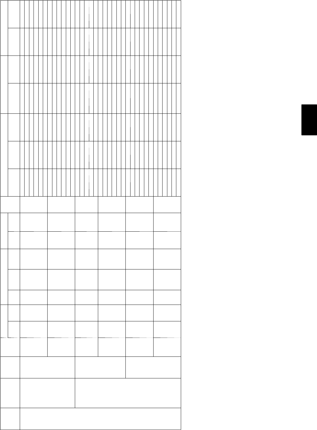
Table 4—Electrical Data--50HJ
UNIT
SIZE
NOMINAL
V --- P H --- H z IFM TYPE CONV
OUTLET
VOLTAGE
RANGE COMPRESSOR (each) OUTDOOR FAN
IFM
FLA
ELECTRIC HEAT POWER SUPPLY * DISCONNECT SIZE
Min Max QTY RLA LRA QTY FLA
CRHEATER
--- --- A 0 0 o r
B00
Actual
kW† FLA MCA MOCP** FLA LRA
004
(3 tons)
208/230--- 1--- 60 STD
NO 187 254 116 88 10.7 4.9
— —/ — —/ — 25.6/ 25.6 30/ 30 25/ 25 101/ 101
001 3.3/ 4.0 15.9/ 18.3 26.0/ 29.0 30/ 30 25/ 27 101/ 101
002 4.9/ 5.8 23.5/ 27.1 35.5/ 40.0 40/ 40 33/ 37 101/ 101
003 6.5/ 8.0 31.4/ 36.3 45.4/ 51.4 50/ 50 42/ 47 101/ 101
004 7.9/ 9.6 37.9/ 43.1 53.5/ 60.0 60/ 60 49/ 55 101/ 101
002+002 9.8/ 11.6 46.9/ 54.2 64.8/ 73.8 70/ 80 60/ 68 101/ 101
YES 187 254 116 88 10.7 4.9
— —/ — —/ — 31.6/ 31.6 35/ 35 30/ 30 106/ 106
001 3.3/ 4.0 15.9/ 18.3 31.6/ 34.0 35/ 35 30/ 32 106/ 106
002 4.9/ 5.8 23.5/ 27.1 40.5/ 45.0 45/ 45 38/ 42 106/ 106
003 6.5/ 8.0 31.4/ 36.3 50.4/ 56.4 60/ 60 47/ 53 106/ 106
004 7.9/ 9.6 37.9/ 43.1 58.5/ 65.0 60/ 70 55/ 61 106/ 106
002+002 9.8/ 11.6 46.9/ 54.2 69.8/ 78.8 70/ 80 65/ 73 106/ 106
208/230--- 3--- 60
STD
NO 187 254 110.3 77 10.7 4.9
— —/ — —/ — 18.5/ 18.5 25/ 25 18/ 18 90/ 90
001 3.3/ 4.0 9.2/ 10.6 18.5/ 19.4 25/ 25 18/ 18 90/ 90
002 4.9/ 5.8 13.6/ 15.6 23.1/ 25.7 25/ 30 21/ 24 90/ 90
003 6.5/ 8.0 18.1/ 20.9 28.8/ 32.3 30/ 35 26/ 30 90/ 90
004 7.9/ 9.6 21.9/ 25.3 33.5/ 37.7 35/ 40 31/ 35 90/ 90
002+002 9.8/ 14.7 33.4/ 38.5 47.8/ 54.2 50/ 60 44/ 50 90/ 90
YES 187 254 110.3 77 10.7 4.9
— —/ — —/ — 24.5/ 24.5 30/ 30 24/ 24 95/ 95
001 3.3/ 4.0 9.2/ 10.6 24.5/ 24.5 30/ 30 24/ 24 95/ 95
002 4.9/ 5.8 13.6/ 15.6 28.1/ 30.7 30/ 35 27/ 29 95/ 95
003 6.5/ 8.0 18.1/ 20.9 33.8/ 37.3 35/ 40 32/ 35 95/ 95
004 7.9/ 9.6 21.9/ 25.3 38.5/ 42.7 35/ 45 36/ 40 95/ 95
002+002 9.8/ 14.7 33.4/ 38.5 52.8/ 59.2 50/ 60 50/ 55 95/ 95
HS
NO 187 254 110.3 77 10.7 5.8
— —/ — —/ — 19.4/ 19.4 25/ 25 19/ 19 120/ 120
001 3.3/ 4.0 9.2/ 10.6 19.4/ 20.5 25/ 25 19/ 19 120/ 120
002 4.9/ 5.8 13.6/ 15.6 24.2/ 26.8 30/ 30 22/ 25 120/ 120
003 6.5/ 8.0 18.1/ 20.9 29.9/ 33.4 35/ 35 28/ 31 120/ 120
004 7.9/ 9.6 21.9/ 25.3 34.6/ 38.8 35/ 40 32/ 36 120/ 120
002+002 9.8/ 14.7 33.4/ 38.5 48.9/ 55.4 50/ 60 45/ 51 120/ 120
YES 187 254 110.3 77 10.7 5.8
— —/ — —/ — 25.4/ 25.4 30/ 30 25/ 25 124/ 124
001 3.3/ 4.0 9.2/ 10.6 25.4/ 25.5 30/ 30 25/ 25 124/ 124
002 4.9/ 5.8 13.6/ 15.6 29.2/ 31.8 35/ 35 28/ 30 124/ 124
003 6.5/ 8.0 18.1/ 20.9 34.9/ 38.4 40/ 40 33/ 36 124/ 124
004 7.9/ 9.6 21.9/ 25.3 39.6/ 43.8 40/ 45 37/ 41 124/ 124
002+002 9.8/ 14.7 33.4/ 38.5 53.9/ 60.4 60/ 70 51/ 56 124/ 124
50HE,HJ

18
Table 4 — Electrical Data--50HJ (cont)
UNIT
SIZE
NOMINAL
V --- P H --- H z IFM TYPE CONV
OUTLET
VOLTAGE
RANGE COMPRESSOR (each) OUTDOOR FAN
IFM
FLA
ELECTRIC HEAT POWER SUPPLY * DISCONNECT SIZE
Min Max QTY RLA LRA QTY FLA
CRHEATER
--- --- A 0 0 o r
B00
Actual
kW† FLA MCA MOCP** FLA LRA
004
(3 tons)
4 6 0 --- 3 --- 6 0
STD
NO 414 508 15.1 39 10.4 2.2
— — — 9.0 20 946
006 5.5 7.2 11.8 20 11 46
007 8.1 10.6 16.0 20 15 46
008 10.6 13.8 20.0 25 18 46
009 12.9 16.8 23.8 25 22 46
YES 414 508 15.1 39 10.4 2.2
— — — 11.7 20 11 48
006 5.5 7.2 15.1 20 13 48
007 8.1 10.6 18.7 20 17 48
008 10.6 13.8 22.7 25 21 48
009 12.9 16.8 26.5 30 24 48
HS
NO 414 508 15.1 39 10.4 2.6
— — — 9.4 20 960
006 5.5 7.2 12.3 20 11 60
007 8.1 10.6 16.5 20 15 60
008 10.6 13.8 20.5 25 19 60
009 12.9 16.8 24.3 25 22 60
YES 414 508 15.1 39 10.4 2.6
— — — 12.1 20 12 62
006 5.5 7.2 15.6 20 14 63
007 8.1 10.6 19.2 20 18 63
008 10.6 13.8 23.2 25 21 63
009 12.9 16.8 27.0 30 25 63
5 7 5 --- 3 --- 6 0
STD NO 518 632 14.2 31 10.4 1.9 — — — 7.3 20 736
YES 518 632 14.2 31 10.4 1.9 — — — 9.5 20 930
HS NO 518 632 14.2 31 10.4 2.0 — — — 7.7 10 840
YES 518 632 14.2 31 10.4 2.0 — — — 9.8 15 10 42
Humidi-
Mi$er
NO 518 632 14.2 31 10.4 2.6 — — — 7.7 10 848
YES 518 632 14.2 31 10.4 2.6 — — — 9.8 15 10 50
50HE,HJ
19
Table 4 — Electrical Data--50HJ (cont)
UNIT
SIZE
NOMINAL
V --- P H --- H z IFM TYPE CONV
OUTLET
VOLTAGE RANGE COMPRESSOR (EACH) OUTDOOR FAN
IFM
FLA
ELECTRIC HEAT POWER SUPPLY DISCONNECT SIZE
Min Max QTY RLA LRA QTY FLA
CRHEATER
--- --- A 0 0 o r
B00
Actual kW{FLA MCA MOCP** FLA LRA
005
(4 ton)
208/230--- 1--- 60 STD
NO 197 254 123.7 126 10.7 4.9
——/— —/— 35.2/ 35.2 45/ 45 34/ 34 139/ 139
001 3.3/ 4.0 15.9/ 18.3 35.2/ 35.2 45/ 45 34/ 34 139/ 139
003 6.5/ 8.0 31.4/ 36.3 45.4/ 51.4 50/ 60 42/ 47 139/ 139
002+002 9.8/ 11.6 46.9/ 54.2 64.8/ 73.8 70/ 80 60/ 68 139/ 139
003+003 13.1/ 16 62.8/ 72.5 84.7/ 96.8 90/ 100 78/ 89 139/ 139
004+004 16.0/ 19.3 75.8/ 87.5 100.9/ 115.5 110/ 125 93/ 106 139/ 139
YES 197 254 123.7 126 10.7 4.9
——/— —/— 41.2/ 41.2 50/ 50 39/ 39 144/ 144
001 3.3/ 4.0 15.9/ 18.3 41.2/ 41.2 50/ 50 39/ 39 144/ 144
003 6.5/ 8.0 31.4/ 36.3 50.4/ 56.4 60/ 60 47/ 53 144/ 144
002+002 9.8/ 11.6 46.9/ 54.2 69.8/ 78.8 70/ 80 65/ 73 144/ 144
003+003 13.1/ 16 62.8/ 72.5 89.7/ 101.8 90/ 100 83/ 95 144/ 144
004+004 16.0/ 19.3 75.8/ 87.5 105.9/ 120.5 110/ 125 98/ 112 144/ 144
208/230--- 3--- 60
STD
NO 187 254 113.5 93 10.7 4.9
——/— —/— 22.5/ 22.5 30/ 30 22/ 22 106/ 106
002 4.9/ 5.8 13.6/ 15.6 23.1/ 25.7 30/ 30 22/ 24 106/ 106
003 6.5/ 8 18.1/ 20.9 28.8/ 32.3 30/ 35 26/ 30 106/ 106
005 12/ 14.7 33.4/ 38.5 47.8/ 54.2 50/ 60 44/ 50 106/ 106
004+004 16/ 19.3 43.8/ 50.5 60.8/ 59.3 70/ 70 56/ 64 106/ 106
YES 187 254 113.5 93 10.7 4.9
——/— —/— 28.5/ 28.5 35/ 35 27/ 27 111/ 111
002 4.9/ 5.8 13.6/ 15.6 28.5/ 30.7 35/ 35 27/ 29 111/ 111
003 6.5/ 8 18.1/ 20.9 33.8/ 37.3 35/ 40 32/ 35 111/ 111
005 12/ 14.7 33.4/ 38.5 52.8/ 59.2 60/ 60 50/ 55 111/ 111
004+004 16/ 19.3 43.8/ 50.5 65.8/ 74.3 70/ 80 62/ 69 111/ 111
HS
NO 187 254 113.5 93 10.7 5.8
——/— —/— 23.4/ 23.4 30/ 30 23/ 23 136/ 136
002 4.9/ 5.8 13.6/ 15.6 24.2/ 26.8 30/ 30 23/ 25 136/ 136
003 6.5/ 8 18.1/ 20.9 29.9/ 33.4 35/ 35 28/ 31 136/ 136
005 12/ 14.7 33.4/ 38.5 48.9/ 55.4 50/ 60 45/ 51 136/ 136
004+004 16/ 19.3 43.8/ 50.5 62.0/ 70.4 70/ 80 57/ 65 136/ 136
YES 187 254 113.5 93 10.7 5.8
——/— —/— 29.4/ 29.4 35/ 35 29/ 29 140/ 140
002 4.9/ 5.8 13.6/ 15.6 29.4/ 31.8 35/ 35 29/ 30 140/ 140
003 6.5/ 8 18.1/ 20.9 34.9/ 38.4 40/ 40 33/ 36 140/ 140
005 12/ 14.7 33.4/ 38.5 53.9/ 60.4 60/ 70 51/ 56 140/ 140
004+004 16/ 19.3 43.8/ 50.5 67.0/ 75.4 70/ 80 63/ 70 140/ 140
4 6 0 --- 3 --- 6 0
STD
NO 414 508 16.4 46.5 10.4 2.2
— — — 10.6 20 10 53
006 5.5 7.2 11.8 20 11 54
008 10.6 13.8 20.0 25 18 54
009 12.9 16.8 23.8 25 22 54
008+008 21.1 27.7 37.3 40 34 54
YES 414 508 16.4 46.5 10.4 2.2
— — — 13.3 20 13 55
006 5.5 7.2 15.1 20 13 56
008 10.6 13.8 22.7 25 21 56
009 12.9 16.8 26.5 30 24 56
008+008 21.1 27.7 40.0 45 37 56
HS
NO 414 508 16.4 46.5 10.4 2.6
— — — 11.0 20 11 67
006 5.5 7.2 12.3 20 11 68
008 10.6 13.8 20.5 25 19 68
009 12.9 16.8 24.3 25 22 68
008+008 21.1 27.7 37.8 40 35 68
YES 414 508 16.4 46.5 10.4 2.6
— — — 13.7 20 13 70
006 5.5 7.2 15.6 20 14 70
008 10.6 13.8 23.2 25 21 70
009 12.9 16.8 27.0 30 25 70
008+008 21.1 27.7 40.5 45 37 70
5 7 5 --- 3 --- 6 0
STD NO 518 632 16.4 40 10.4 1.9 — — — 10.3 15 10 45
YES 518 632 16.4 40 10.4 1.9 — — — 12.5 15 12 47
HS NO 518 632 16.4 40 10.4 2.0 — — — 10.4 15 10 52
YES 518 632 16.4 40 10.4 2.0 — — — 12.6 15 12 53
HUMIDIZ-
ER
NO 518 632 16.4 4 1 0.4 2.6 — — — 10.4 15 10 57
YES 518 632 16.4 4 1 0.4 2.6 — — — 12.6 15 12 59
50HE,HJ
20
Table 4 — Electrical Data--50HJ (cont)
UNIT
SIZE
NOMINAL
V --- P H --- H z IFM TYPE CONV
OUTLET
VOLTAGE RANGE COMPRESSOR (EACH) OUTDOOR FAN
IFM
FLA
ELECTRIC HEAT POWER SUPPLY DISCONNECT SIZE
Min Max QTY RLA LRA QTY FLA
CRHEATER
--- --- A 0 0 o r
B00
Actual kW{FLA MCA MOCP** FLA LRA
006
(5 ton)
208/230--- 1--- 60 STD
NO 187 254 128.8 169 11.5 8.8
——/— —/— 46.3/ 46.3 60/ 60 45/ 45 216/ 216
002 4.9/ 5.8 23.5/ 27.1 46.3/ 46.3 60/ 60 45/ 45 216/ 216
003 6.5/ 8.0 31.4/ 36.3 50.3/ 56.3 60/ 60 46/ 52 216/ 216
002+002 8.7/ 11.6 46.9/ 54.2 69.7/ 78.7 70/ 80 64/ 72 216/ 216
003+003 13.0/ 16.0 62.8/ 72.5 49.5/ 101.6 90/ 110 82/ 93 216/ 216
004+004 15.8/ 19.3 75.8/ 87.5 105.8/ 120.4 110/ 125 97/ 111 216/ 216
YES 187 254 128.8 169 11.5 8.8
——/— —/— 52.3/ 52.3 60/ 60 50/ 50 221/ 221
002 4.9/ 5.8 23.5/ 27.1 52.3/ 52.3 60/ 60 50/ 50 221/ 221
003 6.5/ 8.0 31.4/ 36.3 55.3/ 61.3 60/ 70 52/ 57 221/ 221
002+002 8.7/ 11.6 46.9/ 54.2 74.7/ 83.7 80/ 90 70/ 78 221/ 221
003+003 13.0/ 16.0 62.8/ 72.5 94.5/ 106.6 100/ 110 88/ 99 221/ 221
004+004 15.8/ 19.3 75.8/ 87.5 110.8/ 125.4 125/ 150 103/ 116 221/ 221
208/230--- 3--- 60
STD
NO 187 254 117.3 123 11.5 5.8
——/— —/— 28.9/ 28.9 35/ 35 28/ 28 168/ 168
002 4.9/ 5.8 13.6/ 15.6 28.9/ 28.9 35/ 35 28/ 28 168/ 168
004 7.9/ 9.6 21.9/ 25.3 34.6/ 38.8 35/ 35 32/ 36 168/ 168
005 12.0/ 14.7 33.4/ 38.5 48.9/ 55.4 50/ 50 45/ 51 168/ 168
004+004 15.8/ 19.3 43.8/ 50.5 62/ 70.4 70/ 70 57/ 65 168/ 168
004+005 19.9/ 24.3 55.2/ 63.8 76.3/ 86.9 80/ 80 70/ 80 168/ 168
YES 187 254 117.3 123 11.5 5.8
——/— —/— 34.9/ 34.9 40/ 40 34/ 34 173/ 173
002 4.9/ 5.8 13.6/ 15.6 34.9/ 34.9 40/ 40 34/ 34 173/ 173
004 7.9/ 9.6 21.9/ 25.3 39.6/ 43.8 40/ 40 37/ 41 173/ 173
005 12.0/ 14.7 33.4/ 38.5 53.9/ 60.4 60/ 70 51/ 56 173/ 173
004+004 15.8/ 19.3 43.8/ 50.5 67/ 75.4 70/ 80 63/ 70 173/ 173
004+005 19.9/ 24.3 55.2/ 63.8 81.3/ 91.9 90/ 100 76/ 86 173/ 173
HS
NO 187 254 117.3 123 11.5 7.5
——/— —/— 30.6/ 30.6 35/ 35 30/ 30 187/ 187
002 4.9/ 5.8 13.6/ 15.6 30.6/ 30.6 35/ 35 30/ 30 187/ 187
004 7.9/ 9.6 21.9/ 25.3 36.7/ 40.9 40/ 45 34/ 38 187/ 187
005 12.0/ 14.7 33.4/ 38.5 51.1/ 57.5 60/ 60 47/ 53 187/ 187
004+004 15.8/ 19.3 43.8/ 50.5 64.1/ 72.5 70/ 80 59/ 67 187/ 187
004+005 19.9/ 24.3 55.2/ 63.8 78.4/ 89.1 80/ 90 72/ 82 187/ 187
YES 187 254 117.3 123 11.5 7.5
——/— —/— 36.6/ 36.6 40/ 40 36/ 36 192/ 192
002 4.9/ 5.8 13.6/ 15.6 36.6/ 36.6 40/ 40 36/ 36 192/ 192
004 7.9/ 9.6 21.9/ 25.3 41.7/ 45.9 45/ 50 39/ 43 192/ 192
005 12.0/ 14.7 33.4/ 38.5 56.6/ 62.5 60/ 70 53/ 58 192/ 192
004+004 15.8/ 19.3 43.8/ 50.5 69.1/ 77.5 70/ 80 65/ 72 192/ 192
004+005 19.9/ 24.3 55.2/ 63.8 83.4/ 94.1 90/ 100 78/ 87 192/ 192
4 6 0 --- 3 --- 6 0
STD
NO 414 508 1 9 62 10.8 2.6
— — — 14.7 20 14 84
006 5.5 7.2 14.7 20 10 84
008 10.6 13.8 20.5 25 19 84
009 12.9 16.8 24.3 25 22 84
008+008 21.1 27.7 37.8 40 35 84
008+009 23.4 30.1 40.8 45 38 84
YES 414 508 1 9 62 10.8 2.6
— — — 17.4 20 17 86
006 5.5 7.2 17.4 20 17 87
008 10.6 13.8 23.2 25 21 87
009 12.9 16.8 27.0 30 25 87
008+008 21.1 27.7 40.5 45 37 87
008+009 23.4 30.1 43.5 45 40 87
HS
NO 414 508 1 9 62 10.8 3.4
— — — 15.5 20 15 93
006 5.5 7.2 15.5 20 15 94
008 10.6 13.8 21.5 25 20 94
009 12.9 16.8 25.3 30 23 94
008+008 21.1 27.7 38.8 40 36 94
008+009 23.4 30.1 41.8 45 38 94
YES 414 508 1 9 62 10.8 3.4
— — — 18.2 20 18 96
006 5.5 7.2 18.2 20 18 96
008 10.6 13.8 24.2 25 22 96
009 12.9 16.8 28.0 30 26 96
008+008 21.1 27.7 41.5 45 38 96
008+009 23.4 30.1 44.5 45 41 96
5 7 5 --- 3 --- 6 0
STD NO 518 632 17.1 50 10.6 2.0 — — — 11.5 15 11 63
YES 518 632 17.1 50 10.6 2.0 — — — 13.6 15 13 64
HS NO 518 632 17.1 50 10.6 2.8 — — — 12.3 15 12 72
YES 518 632 17.1 50 10.6 2.8 — — — 14.4 15 14 73
HUMIDIZ-
ER
NO 518 632 17.1 50 10.6 3.4 — — — 12.2 15 12 76
YES 518 632 17.1 50 10.6 3.4 — — — 14.4 20 14 77
50HE,HJ
21
Table 4 — Electrical Data--50HJ (cont)
UNIT
SIZE NOMINAL
V --- P H --- H z
IFM
TYPE
CONV
OUTLET
VOLTAGE
RANGE COMPRESSOR (each) OUTDOOR FAN
IFM
FLA
ELECTRIC HEAT POWER SUPPLY * DISCONNECT SIZE
Min Max QTY RLA LRA QTY FLA
CRHEATER
--- --- --- A 0 0 o r
B00
Actual
kW† FLA MCA MOCP** FLA LRA
007
(6 ton)
208/230--- 3--- 60
STD
NO 187 254 120.5 156 11.4 5.8
——/— —/— 32.8/ 32.8 40/ 40 32/ 32 200/ 200
002 4.9/ 5.8 13.6/ 15.6 32.8/ 32.8 40/ 40 32/ 32 200/ 200
004 7.9/ 9.6 21.9/ 25.3 34.6/ 38.8 40/ 40 32/ 36 200/ 200
005 12.0/ 14.7 33.4/ 38.5 48.9/ 55.4 50/ 50 45/ 51 200/ 200
004+004 15.8/ 19.3 43.8/ 50.5 62.0/ 70.4 70/ 80 57/ 65 200/ 200
004+005 19.9/ 24.3 55.2/ 63.8 76.3/ 86.9 80/ 90 70/ 80 200/ 200
YES 187 254 120.5 156 11.4 5.8
——/— —/— 38.8/ 38.8 45/ 45 37/ 37 205/ 205
002 4.9/ 5.8 13.6/ 15.6 38.8/ 38.8 45/ 45 37/ 37 205/ 205
004 7.9/ 9.6 21.9/ 25.3 39.6/ 43.8 45/ 45 37/ 41 205/ 205
005 12.0/ 14.7 33.4/ 38.5 53.9/ 60.4 60/ 70 51/ 56 205/ 205
004+004 15.8/ 19.3 43.8/ 50.5 67.0/ 75.4 70/ 80 63/ 70 205/ 205
004+005 19.9/ 24.3 55.2/ 63.8 76.3/ 86.9 90/ 100 76/ 86 205/ 205
HS
NO 187 254 120.5 156 11.4 7.5
——/— —/— 34.5/ 34.5 40/ 40 34/ 34 219/ 219
002 4.9/ 5.8 13.6/ 15.6 34.5/ 34.5 40/ 40 34/ 34 219/ 219
004 7.9/ 9.6 21.9/ 25.3 36.7/ 40.9 40/ 45 34/ 38 219/ 219
005 12.0/ 14.7 33.4/ 38.5 51.1/ 57.5 60/ 60 47/ 53 219/ 219
004+004 15.8/ 19.3 43.8/ 50.5 64.1/ 72.5 70/ 80 59/ 67 219/ 219
004+005 19.9/ 24.3 55.2/ 63.8 78.4/ 89.1 80/ 90 72/ 82 219/ 219
YES 187 254 120.5 156 11.4 7.5
——/— —/— 40.5/ 40.5 45/ 45 39/ 39 224/ 224
002 4.9/ 5.8 13.6/ 15.6 40.5/ 40.5 45/ 45 39/ 39 224/ 224
004 7.9/ 9.6 21.9/ 25.3 41.7/ 45.9 45/ 50 39/ 43 224/ 224
005 12.0/ 14.7 33.4/ 38.5 56.1/ 62.5 60/ 70 53/ 58 224/ 224
004+004 15.8/ 19.3 43.8/ 50.5 69.1/ 77.5 70/ 80 65/ 72 224/ 224
004+005 19.9/ 24.3 55.2/ 63.8 83.4/ 94.1 90/ 100 78/ 87 224/ 224
4 6 0 --- 3 --- 6 0
STD
NO 414 508 19.6 75 10.6 2.6
— — — 15.2 20 15 97
006 5.5 7.2 15.2 20 15 97
008 10.6 13.8 20.5 25 19 97
009 12.9 16.8 24.3 25 22 97
008+008 21.1 27.7 37.8 40 35 97
008+009 23.4 30.7 41.6 45 38 97
YES 414 508 19.6 75 10.6 2.6
— — — 17.9 20 17 99
006 5.5 7.2 17.9 20 17 99
008 10.6 13.8 23.2 25 21 99
009 12.9 16.8 27.0 30 25 99
008+008 21.1 27.7 40.5 45 37 99
008+009 23.4 30.7 44.3 45 41 99
HS
NO 414 508 19.6 75 10.6 3.4
— — — 16.0 20 16 106
006 5.5 7.2 16.0 20 16 107
008 10.6 13.8 21.5 25 20 107
009 12.9 16.8 25.3 30 23 107
008+008 21.1 27.7 38.8 40 36 107
008+009 23.4 30.7 42.6 45 39 107
YES 414 508 19.6 75 10.6 3.4
— — — 18.7 25 18 108
006 5.5 7.2 18.7 25 18 109
008 10.6 13.8 24.2 25 22 109
009 12.9 16.8 28.0 30 26 109
008+008 21.1 27.7 41.5 45 38 109
008+009 23.4 30.7 45.3 50 42 109
5 7 5 --- 3 --- 6 0
STD NO 518 632 17.7 56 10.6 2.0 — — — 11.5 15 11 63
YES 518 632 17.7 56 10.6 2.0 — — — 13.6 15 13 64
HS NO 518 632 17.7 56 10.6 2.8 — — — 12.3 15 12 72
YES 518 632 17.7 56 10.6 2.8 — — — 14.4 20 14 73
HUMI-
DIMIZ-
ER
NO 518 632 17.7 56 10.6 3.4 — — — 12.2 15 12 76
YES 518 632 17.7 56 10.6 3.4 — — — 14.4 20 14 77
50HE,HJ

22
Table 4 — Electrical Data--50HJ (cont)
UNIT
SIZE
NOMINAL
V --- P H --- H z
IFM
TYPE
CONV
OUTLET
VOLTAGE RANGE COMPRESSOR (each) OUTDOOR FAN
IFM
FLA
ELECTRIC HEAT POWER SUPPLY* DISCONNECT SIZE
Min Max QTY RLA LRA QTY FLA
CRHEATER
--- --- A 0 0 o r
B00
Actual kW{FLA MCA MOCP** FLA LRA
008
(7.5
ton)
208/230--- 3--- 60
STD
NO 187 254 212.4 88 21.4 7.5
——/— —/— 38.2/ 38.2 45/ 45 40/ 40 242/ 242
017 7.8/ 9.6 21.7/ 25.0 38.2/ 40.6 45/ 45 40/ 40 242/ 242
010 12.0/ 14.7 33.4/ 38.5 51.1/ 57.5 60/ 60 47/ 53 242/ 242
011 18.6/ 22.8 51.7/ 59.7 74.0/ 84.0 80/ 90 68/ 77 242/ 242
012 24.0/ 29.4 66.7/ 77.0 92.8/ 105.6 100/ 110 85/ 97 242/ 242
012+017 31.8/ 38.9 88.4/ 102.0 119.9/ 136.9 125/ 150 110/ 126 242/ 242
YES 187 254 212.4 88 21.4 7.5
——/— —/— 44.2/ 44.2 50/ 50 46/ 46 247/ 247
017 7.8/ 9.6 21.7/ 25.0 44./ 45.6 50/ 50 46/ 46 247/ 247
010 12.0/ 14.7 33.4/ 38.5 56.1/ 62.5 60/ 70 53/ 58 247/ 247
011 18.6/ 22.8 51.7/ 59.7 79.0/ 89.0 80/ 90 74/ 83 247/ 247
012 24.0/ 29.4 66.7/ 77.0 97.8/ 110.6 100/ 125 91/ 103 247/ 247
012+017 31.8/ 38.9 88.4/ 102.0 124.9/ 141.9 125/ 150 116/ 131 247/ 247
HS
NO 187 254 212.4 88 21.4 10.6
——/— —/— 41.3/ 41.3 45/ 45 44/ 44 267/ 267
017 7.8/ 9.6 21.7/ 25.0 41.3/ 44.5 50/ 50 44/ 44 267/ 267
010 12.0/ 14.7 33.4/ 38.5 54.9/ 61.4 60/ 70 51/ 56 267/ 267
011 18.6/ 22.8 51.7/ 59.7 77.9/ 87.8 80/ 90 72/ 81 267/ 267
012 24.0/ 29.4 66.7/ 77.0 96.6/ 109.5 100/ 110 89/ 101 267/ 267
012+017 31.8/ 38.9 88.4/ 102.0 123.7/ 140.8 125/ 150 114/ 129 267/ 267
YES 187 254 212.4 88 21.4 10.6
——/— —/— 47.3/ 47.3 50/ 50 49/ 49 271/ 271
017 7.8/ 9.6 21.7/ 25.0 47.3/ 49.5 60/ 60 49/ 49 271/ 271
010 12.0/ 14.7 33.4/ 38.5 59.9/ 66.4 70/ 70 56/ 62 271/ 271
011 18.6/ 22.8 51.7/ 59.7 82.9/ 92.8 90/ 100 77/ 86 271/ 271
012 24.0/ 29.4 66.7/ 77.0 101.6/ 114.5 110/ 125 94/ 106 271/ 271
012+017 31.8/ 38.9 88.4/ 102.0 128.7/ 145.8 150/ 150 119/ 135 271/ 271
4 6 0 --- 3 --- 6 0
STD
NO 414 508 26.4 44 20.7 3.4
— — — 19.2 20 20 121
016 12.8 16.7 25.1 20 23 121
013 15.2 19.8 29.1 20 27 121
014 25.5 33.4 46.0 50 42 121
015 30.3 39.7 53.9 60 50 121
014+016 38.3 50.2 66.9 70 62 121
YES 414 508 26.4 44 20.7 3.4
— — — 21.9 20 23 123
016 12.8 16.7 28.5 20 26 123
013 15.2 19.8 31.8 35 29 123
014 25.5 33.4 48.7 50 45 123
015 30.3 39.7 56.6 60 52 123
014+016 38.3 50.2 69.6 70 64 123
HS
NO 414 508 26.4 44 20.7 4.8
— — — 20.6 20 22 133
016 12.8 16.7 26.9 20 25 134
013 15.2 19.8 30.8 35 28 134
014 25.5 33.4 47.8 50 44 134
015 30.3 39.7 55.6 60 51 134
014+016 38.3 50.2 68.7 70 63 134
YES 414 508 26.4 44 20.7 4.8
— — — 23.3 20 24 135
016 12.8 16.7 30.3 35 27 136
013 15.2 19.8 33.5 35 31 136
014 25.5 33.4 50.5 60 46 136
015 30.3 39.7 58.3 60 54 136
014+016 38.3 50.2 71.4 80 66 136
50HE,HJ
23
Table 4 — Electrical Data--50HJ (cont)
UNIT
SIZE
NOMINAL
V --- P H --- H z
IFM
TYPE
CONV
OUTLET
VOLTAGE RANGE COMPRESSOR (each) OUTDOOR FAN
IFM
FLA
ELECTRIC HEAT POWER SUPPLY* DISCONNECT SIZE
Min Max QTY RLA LRA QTY FLA
CRHEATER
--- --- A 0 0 o r
B00
Actual kW{FLA MCA MOCP** FLA LRA
008
(7.5
ton)
5 7 5 --- 3 --- 6 0
STD
NO 518 632 24.8 34 20.6 2.8
— — — 14.8 20 16 91
018 17.0 16.4 23.9 25 22 91
019 34.0 32.7 44.4 45 41 91
YES 518 632 24.8 34 20.6 2.8
— — — 17.0 20 18 93
018 17.0 16.4 26.6 30 24 93
019 34.0 32.7 44.4 45 43 93
HS
NO 518 632 24.8 34 20.6 3.3
— — — 15.3 20 16 101
018 17.0 16.4 24.6 25 23 101
019 34.0 32.7 45.0 50 42 101
YES 518 632 24.8 34 20.6 3.3
— — — 17.5 20 18 103
018 17.0 16.4 27.2 30 25 103
019 34.0 32.7 45.0 50 44 103
HUMI-
DIMIZ-
ER
NO 518 632 24.8 34 20.7 4.8
— — — 15.8 20 17 104
018 17.0 16.4 25.5 30 23 104
019 34.0 32.7 45.7 50 42 104
YES 518 632 24.8 34 20.7 4.8
— — — 17.9 20 19 106
018 17.0 16.4 27.9 30 25 106
019 34.0 32.7 45.7 50 44 106
50HE,HJ

24
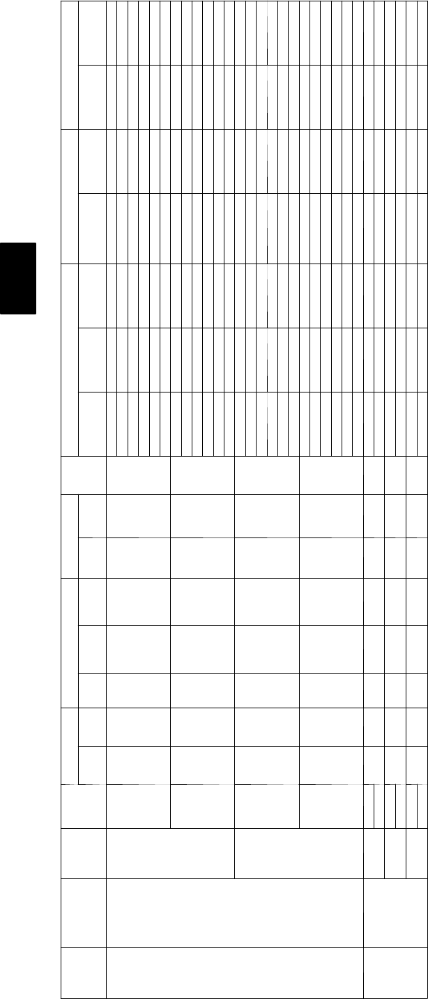
Table 4 — Electrical Data--50HJ (cont)
UNIT
SIZE
NOMINAL
V --- P H --- H z
IFM
TYPE
CONV
OUTLET
VOLTAGE RANGE COMPRESSOR (each) OUTDOOR FAN
IFM
FLA
ELECTRIC HEAT POWER SUPPLY DISCONNECT SIZE
Min Max QTY RLA LRA QTY FLA
CRHEATER
--- --- A 0 0 o r
B00
Actual kW{FLA MCA MOCP** FLA LRA
009
(8.5
ton)
208/230--- 3--- 60
STD
NO 187 254 213.4 105 21.4 7.5
——/ — —/ — 40.2/ 40.2 45/ 45 42/ 42 276/ 276
017 7.8/ 9.6 21.7/ 25.0 40.2/ 40.6 45/ 45 42/ 42 276/ 276
010 12.0/ 14.7 33.4/ 38.5 51.1/ 57.5 60/ 60 47/ 53 276/ 276
011 18.6/ 22.8 51.7/ 59.7 74.0/ 84.0 80/ 90 68/ 77 276/ 276
012 24.0/ 29.4 66.7/ 77.0 92.8/ 105.6 100/ 110 85/ 97 276/ 276
012+017 31.8/ 38.9 88.4/ 102.0 119.9/ 136.9 110/ 150 110/ 126 276/ 276
YES 187 254 213.4 105 21.4 7.5
——/ — —/ — 46.2/ 46.2 50/ 50 48/ 48 281/ 281
017 7.8/ 9.6 21.7/ 25.0 46.2/ 46.2 50/ 50 48/ 48 281/ 281
010 12.0/ 14.7 33.4/ 38.5 56.1/ 62.5 60/ 70 53/ 58 281/ 281
011 18.6/ 22.8 51.7/ 59.7 79.0/ 89.0 80/ 90 74/ 83 281/ 281
012 24.0/ 29.4 66.7/ 77.0 97.8/ 110.6 100/ 125 91/ 103 281/ 281
012+017 31.8/ 38.9 88.4/ 102.0 124.9/ 141.9 125/ 150 116/ 131 281/ 281
HS
NO 187 254 213.4 105 21.4 10.6 ——/ — —/ — 43.3/ 43.3 50/ 50 46/ 46 301/ 301
017 7.8/ 9.6 21.7/ 25.0 43.3/ 44.5 50/ 50 46/ 46 301/ 301
010 12.0/ 14.7 33.4/ 38.5 54.9/ 61.4 60/ 70 51/ 56 301/ 301
011 18.6/ 22.8 51.7/ 59.7 77.9/ 87.8 80/ 90 72/ 81 301/ 301
012 24.0/ 29.4 66.7/ 77.0 96.6/ 109.5 100/ 110 89/ 101 301/ 301
012+017 31.8/ 38.9 88.4/ 102.0 123.7/ 140.8 125/ 150 114/ 129 301/ 301
YES 187 254 213.4 105 21.4 10.6
——/ — —/ — 49.3/ 49.3 60/ 60 51/ 51 305/ 305
017 7.8/ 9.6 21.7/ 25.0 49.3/ 49.5 60/ 60 51/ 51 305/ 305
010 12.0/ 14.7 33.4/ 38.5 59.9/ 66.4 70/ 70 56/ 62 305/ 305
011 18.6/ 22.8 51.7/ 59.7 82.9/ 92.8 90/ 100 77/ 86 305/ 305
012 24.0/ 29.4 66.7/ 77.0 101.6/ 114.5 110/ 125 94/ 106 305/ 305
012+017 31.8/ 38.9 88.4/ 102.0 128.7/ 145.8 150/ 150 119/ 135 305/ 305
4 6 0 --- 3 --- 6 0
STD
NO 414 508 27.4 55 20.7 3.4
— — — 21.5 30 23 143
016 12.8 16.7 25.1 30 23 143
013 15.2 19.8 29.1 30 27 143
014 25.5 33.4 46.0 50 42 143
015 30.3 39.7 53.9 60 50 143
014+016 38.3 50.2 66.9 70 62 143
YES 414 508 27.4 55 20.7 3.4
— — — 24.2 30 25 145
016 12.8 16.7 28.5 30 26 145
013 15.2 19.8 31.8 35 29 145
014 25.5 33.4 48.7 50 45 145
015 30.3 39.7 56.6 60 52 145
014+016 38.3 50.2 69.6 70 64 145
HS
NO 414 508 27.4 55 20.7 4.8
— — — 22.9 30 24 155
016 12.8 16.7 26.9 30 25 156
013 15.2 19.8 30.8 35 28 156
014 25.5 33.4 47.8 50 44 156
015 30.3 39.7 55.6 60 51 156
014+016 38.3 50.2 68.7 70 63 156
YES 414 508 27.4 55 20.7 4.8
— — — 25.6 30 27 157
016 12.8 16.7 30.3 35 27 158
013 15.2 19.8 33.5 35 31 158
014 25.5 33.4 50.5 60 46 158
015 30.3 39.7 58.3 60 54 158
014+016 38.3 50.2 71.4 80 66 158
50HE,HJ
25
Table 4 — Electrical Data--50HJ (cont)
UNIT
SIZE
NOMINAL
V --- P H --- H z
IFM
TYPE
CONV
OUTLET
VOLTAGE RANGE COMPRESSOR (each) OUTDOOR FAN
IFM
FLA
ELECTRIC HEAT POWER SUPPLY DISCONNECT SIZE
Min Max QTY RLA LRA QTY FLA
CRHEATER
--- --- A 0 0 o r
B00
Actual kW{FLA MCA MOCP** FLA LRA
009
(8.5
ton)
5 7 5 --- 3 --- 6 0
STD
NO 518 632 26.4 44 20.6 2.8
— — — 18.4 25 19 111
018 17.0 16.4 23.9 25 22 111
019 34.0 32.7 44.4 45 41 111
YES 518 632 26.4 44 20.6 2.8
— — — 20.6 25 21 113
018 17.0 16.4 26.6 30 24 113
019 34.0 32.7 44.4 45 43 113
HS
NO 518 632 26.4 44 20.6 3.3
— — — 18.9 25 20 121
018 17.0 16.4 24.6 25 23 121
019 34.0 32.7 45.0 50 41 121
YES 518 632 26.4 44 20.6 3.3
— — — 21.1 25 22 123
018 17.0 16.4 27.9 30 25 123
019 34.0 32.7 45.0 50 43 123
HUMI-
DIMIZ-
ER
NO 518 632 26.4 44 20.7 3.3
— — — 19.4 25 20 124
018 17.0 16.4 25.2 30 23 124
019 34.0 32.7 45.7 50 42 124
YES 518 632 26.4 44 20.7 3.3
— — — 21.5 25 22 126
018 17.0 16.4 27.9 30 25 126
019 34.0 32.7 48.3 50 44 126
50HE,HJ
26
Table 4 — Electrical Data--50HJ (cont)
UNIT
SIZE
NOMINAL
V --- P H --- H z
IFM
TYPE
CONV
OUT-
LET
VOLTAGE
RANGE COMPRESSOR (each) OUTDOOR FAN
IFM
FLA
ELECTRIC HEAT POWER SUPPLY DISCONNECT SIZE
Min Max QTY RLA LRA QTY FLA
CRHEATER
--- --- A 0 0 o r
B00
Actual kW{FLA MCA MOCP** FLA LRA
012
(10 ton)
208/230--- 3--- 60
STD
NO 187 254 217.6 125 21.4 10.6
——/ — —/ — 53.0/ 53.0 60/ 60 56/ 56 341/ 341
017 7.8/ 9.6 21.7/ 25.0 53.0/ 53.0 60/ 60 56/ 56 341/ 341
010 12.0/ 14.7 33.4/ 38.5 54.9/ 61.4 60/ 70 56/ 56 341/ 341
012 24.0/ 29.4 66.7/ 77.0 96.6/ 109.5 100/ 110 89/ 101 341/ 341
012+017 31.8/ 38.9 88.4/ 102.0 123.7/ 140.8 125/ 150 114/ 129 341/ 341
012+010 37.5/ 45.9 104.2/ 104.2 143.5/ 133.5 150/ 150 132/ 151 341/ 341
YES 187 254 217.6 125 21.4 10.6
——/ — —/ — 59.0/ 59.0 70/ 70 61/ 61 345/ 345
017 7.8/ 9.6 21./ 25.0 59.0/ 59.0 70/ 70 61/ 61 345/ 345
010 12.0/ 14.7 33.4/ 38.5 59.9/ 66.4 70/ 70 61/ 62 345/ 345
012 24.0/ 29.4 66.7/ 77.0 101.6/ 114.5 110/ 125 94/ 106 345/ 345
012+017 31.8/ 38.9 88.4/ 102.0 128.7/ 145.8 150/ 150 119/ 135 345/ 345
012+010 37.5/ 45.9 104.2/ 120.3 148.5/ 137.5 150/ 150 138/ 156 345/ 345
HS
NO 187 254 217.6 125 21.4 15
——/ — —/ — 57.4/ 57.4 70/ 70 61/ 61 364/ 364
017 7.8/ 9.6 21.7/ 25.0 57.4/ 57.4 70/ 70 62/ 62 364/ 364
010 12.0/ 14.7 33.4/ 38.5 60.4/ 66.9 70/ 80 61/ 62 364/ 364
012 24.0/ 29.4 66.7/ 77.0 102.1/ 115.0 110/ 125 94/ 106 364/ 364
012+017 31.8/ 38.9 88.4/ 102.0 129.2/ 146.3 150/ 150 119/ 135 364/ 364
012+010 37.5/ 45.9 104.2/ 120.3 149.0/ 139.0 150/ 175 137/ 156 364/ 364
YES 187 254 217.6 125 21.4 15
——/ — —/ — 63.4/ 63.4 70/ 70 66/ 66 369/ 369
017 7.8/ 9.6 21./ 25.0 63.4/ 63.4 70/ 70 66/ 66 369/ 369
010 12.0/ 14.7 33.4/ 38.5 65.4/ 71.9 80/ 80 66/ 67 369/ 369
012 24.0/ 29.4 66.7/ 77.0 107.1/ 120.0 110/ 125 99/ 111 369/ 369
012+017 31.8/ 38.9 88.4/ 102.0 134.2/ 151.3 150/ 175 124/ 140 369/ 369
012+010 37.5/ 45.9 104.2/ 120.3 154.0/ 143.0 175/ 175 143/ 161 369/ 369
4 6 0 --- 3 --- 6 0
STD
NO 414 508 28.3 62.5 20.7 4.8
———24.9 30 26 170
016 12.8 16.7 26.9 30 26 171
013 15.2 19.8 30.8 35 28 171
015 30.3 39.7 55.6 60 51 171
014+016 38.3 50.2 68.7 70 63 171
015+013 45.9 60.1 66.1 80 75 171
YES 414 508 28.3 62.5 20.7 4.8
———27.6 30 29 172
016 12.8 16.7 30.3 35 29 173
013 15.2 19.8 33.5 35 31 173
015 30.3 39.7 58.3 60 54 173
014+016 38.3 50.2 71.4 80 66 173
015+013 45.9 60.1 70.1 80 77 173
HS
NO 414 508 28.3 62.5 20.7 7.4
———27.5 30 29 182
016 12.8 16.7 30.1 35 29 182
13 15.2 19.8 34.1 40 31 182
15 30.3 39.7 58.9 60 54 182
014+016 38.3 50.2 71.9 80 66 182
015+013 45.9 60.1 69.4 80 78 182
YES 414 508 28.3 62.5 20.7 7.4
———30.2 35 32 184
016 12.8 16.7 33.5 40 32 184
013 15.2 19.8 36.8 40 34 184
015 30.3 39.7 61.6 70 57 184
014+016 38.3 50.2 74.6 80 69 184
015+013 45.9 60.1 73.4 80 80 184
50HE,HJ

27
Table 4 — Electrical Data--50HJ (cont)
UNIT
SIZE
NOMINAL
V --- P H --- H z
IFM
TYPE
CONV
OUT-
LET
VOLTAGE
RANGE COMPRESSOR (each) OUTDOOR FAN
IFM
FLA
ELECTRIC HEAT POWER SUPPLY DISCONNECT SIZE
Min Max QTY RLA LRA QTY FLA
CRHEATER
--- --- A 0 0 o r
B00
Actual kW{FLA MCA MOCP** FLA LRA
012
(10 ton) 5 7 5 --- 3 --- 6 0
STD
NO 518 632 26.3 50 20.6 3.3
———18.7 25 20 133
18 17.0 16.4 24.6 25 23 133
019 34.0 32.7 45.0 50 41 133
018+019 51.0 49.1 53.2 60 60 133
YES 518 632 26.3 50 20.6 3.3
———20.8 25 22 135
018 17.0 16.4 27.2 30 25 135
019 34.0 32.7 45.0 50 43 135
018+019 51.0 49.1 55.8 60 62 135
HS
NO 518 632 26.3 50 20.6 5.6
———21.0 25 22 139
018 17.0 16.4 27.4 30 25 139
019 34.0 32.7 47.9 50 44 139
018+019 51.0 49.1 56.1 70 63 139
YES 518 632 26.3 50 20.6 5.6
———23.1 25 24 141
018 17.0 16.4 30.1 35 27 141
019 34.0 32.7 47.9 60 46 141
018+019 51.0 49.1 58.7 70 65 141
HUMI-
DIMIZ-
ER
NO 518 632 26.3 50 20.7 7.4
———21.2 25 23 146
018 17.0 16.4 27.8 30 26 146
019 34.0 32.7 48.3 50 44 146
018+019 51.0 49.1 56.5 70 63 146
YES 518 632 26.3 50 20.7 7.4
———23.4 25 25 148
018 17.0 16.4 30.5 50 28 148
019 34.0 32.7 50.9 60 46 148
018+019 51.0 49.1 59.1 70 65 148
50HE,HJ
28
Table 4 — Electrical Data--50HJ (cont)
UNIT SIZE NOMINAL
V --- P H --- H z
IFM
TYPE
CONV
OUTLET
VOLTAGE
RANGE COMPRESSOR (each) OUTDOOR FAN
IFM
FLA
ELECTRIC HEAT POWER SUPPLY DISCONNECT SIZE
Min Max QTY RLA LRA QTY FLA
CRHEATER
--- --- A 0 0 O R
B00
Actual kW{FLA MCA MOCP** FLA LRA
014
(12.5
tons)
208/230--- 3--- 60 STD
NO 187 254 219 156 21.4 15
——/ — —/ — 60.6/ 60.6 70/ 70 64/ 64 426/426
017 7.8/ 9.6 21.7// 25.0 60.6/ 60.6 70/ 70 64/ 64 426/426
010 12.0/ 14.7 33.4/ 38.5 60.4/ 66.9 70/ 70 64/ 64 426/426
012 24.0/ 29.4 66.7/ 77.0 102.1/ 115.0 110/ 125 94/ 106 426/426
012+017 31.8/ 38.9 88.4/ 102.0 129.2/ 146.3 150/ 150 119/ 135 426/426
012+010 37.5/ 45.9 104.2/ 120.3 149.0/ 139.0 150/ 175 137/ 156 426/426
YES 187 254 219 156 21.4 15
——/ — —/ — 66.6/ 66.6 70/ 70 70/ 70 431/431
016 7.8/ 9.6 21.7/ 25.0 66.6/ 66.6 70/ 70 70/ 70 431/431
013 12.0/ 14.7 33.4/ 38.5 65.4/ 71.9 80/ 80 70/ 70 431/431
015 24.0/ 29.4 66.7/ 77.0 107.1/ 120.0 110/ 125 99/ 111 431/431
014+016 31.8/ 38.9 88.4/ 102.0 134.2/ 151.3 150/ 175 124/ 140 431/431
015+013 37.5/ 45.9 104.2/ 120.3 154.0/ 143.0 175/ 175 143/ 161 431/431
4 6 0 --- 3 --- 6 0 STD
NO 414 508 2 9 70 20.7 7.4
———29.1 35 31 197
016 12.8 16.7 30.1 35 31 197
013 15.2 19.8 34.1 40 31 197
015 30.3 39.7 58.9 60 54 197
014+016 38.3 50.2 71.9 80 66 197
015+013 45.9 60.1 69.4 80 78 197
YES 414 508 2 9 70 20.7 7.4
———31.8 35 33 199
016 12.8 16.7 33.5 40 33 199
013 15.2 19.8 36.8 40 34 199
015 30.3 39.7 61.6 70 57 199
014+016 38.3 50.2 74.6 80 69 199
015+013 45.9 60.1 73.4 80 80 199
5 7 5 --- 3 --- 6 0
STD
NO 518 632 27.4 54 20.6 5.6
———23.5 30 25 147
018 17.0 16.4 27.4 30 25 147
019 34.0 32.7 47.9 50 44 147
018+019 51.0 49.1 56.1 70 63 147
YES 518 632 27.4 54 20.6 5.6
———25.6 30 27 149
018 17.0 16.4 30.1 35 27 149
019 34.0 32.7 47.9 50 46 149
018+019 51.0 49.1 58.7 70 65 149
HUMI-
DIMIZ-
ER
NO 518 632 27.4 54 20.7 7.4
———23.7 30 25 154
18 17.0 16.4 27.8 35 26 154
019 34.0 32.7 48.3 50 44 154
018+019 51.0 49.1 56.5 70 63 154
YES 518 632 27.4 54 20.7 7.4
———25.9 35 27 155
18 17.0 16.4 30.5 40 28 155
019 34.0 32.7 50.9 60 46 155
018+019 51.0 49.1 59.1 80 65 155
FLA ---Full Load Amps
HACR --- Heating, Air Conditioning and Refrigeration
IFM --- Indoor (Evaporator) Fan Motor
LRA --- Locked Rotor Amps
MCA --- Minimum Circuit Amps
MOCP --- Maximum Overcurrent Protection
NEC --- National Electrical Code
OFM --- Outdoor (Condenser) Fan Motor
RLA --- Rated Load Amps
NOTES:
* The values listed in this table do not include power exhaust. See power exhaust table for power exhaust requirements.
** Fuse or HACR breaker
{Heater capacity (kW) is based on heater voltage of 240v, 480v or 575v. If power distribution voltage to unit varies from rated heater voltage, heater kW will vary accordingly
50HE,HJ
29
Step 6 —Adjust Factory-Installed Options
CobraEnergy Recovery Units
Please refer to the supplement provided for information on
installing and operating the factory optional COBRA Energy
Recovery Units. These units are equipped with a factory--installed
energy recovery unit and have different installation and operation
procedures than the standard unit.
Humidi--MizerAdaptive Dehumidification
System
Humidi--MiZer system operation can be controlled by field
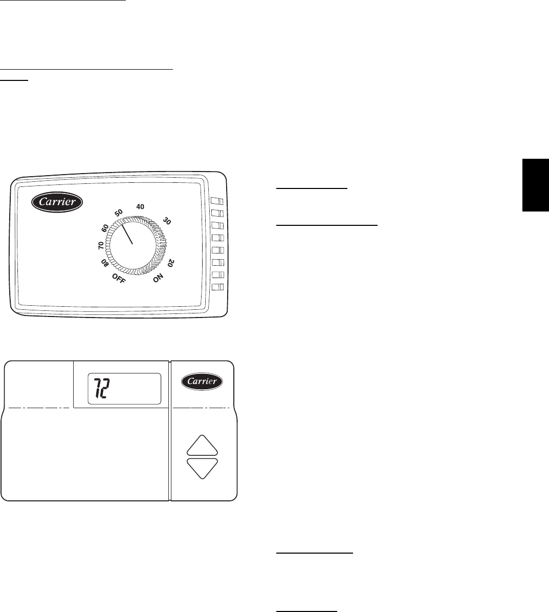
installation of a Carrier--approved humidistat. (See Fig. 14.)
NOTE: A light commercial Thermidistatdevice (Fig. 15) can
be used instead of the humidistat if desired. The Thermidistat
device includes a thermostat and a humidistat. The humidistat is
normally used in applications where a temperature sensor is
already provided (units with PremierLinkcontrol).
% RELATIVE HUMIDITY
C06126
Fig. 14 --- Accessory Field--Installed Humidistat
C06127
Fig. 15 --- Light Commercial thermidistat Device
To install the humidistat:
1. Route humidistat cable through hole provided in unit
control box.
2. Some models may be equipped with a raceway built into
the corner post on the left side of control box (See Fig.
13.) This raceway provides the required clearance between
high--voltage and low voltage wiring. For models without
a raceway, ensure to provide the NEC required clearance
between high--voltage and low--voltage wiring.
3. Use a wire nut to connect humidistat cable into low-
voltage wiring as shown in Fig. 16.
To install Thermidistat device:
1. Route Thermidistat cable through hole provided in unit
control box.
2. Some models may be equipped with a raceway built into
the corner post on the left side of control box (See Fig.
13.) This raceway provides the required clearance between
high--voltage and low voltage wiring. For models without
a raceway, ensure to provide the NEC required clearance
between high--voltage and low--voltage wiring.
3. A field-supplied relay must be installed between the
thermidistat and the Humidi-Mizer circuit (recommended
relay: HN612KK324). (See Fig. 17.) The relay coil is
connected between the DEHUM output and C (common)
of the unit. The relay controls the Humidi-MiZer solenoid
valve and must be wired between the Humidi-MiZer fuse
and the low-pressure switch. Refer to the installation
instructions included with the Carrier Light Commercial
Thermidistat device for more information.
Disconnect Switch
The optional disconnect switch is non--fused. The switch has the
capability of being locked in place for safety purposes.
Manual Outdoor Damper
The outdoor--air hood and screen are attached to the basepan at
the bottom of the unit for shipping.
Assembly:
1. Determine quantity of ventilation required for building.
Record amount for use in Step 8.
2. Remove and save outdoor air opening panel and screws.
(See Fig. 18.)
3. Remove evaporator coil access panel. Separate hood and
screen from basepan by removing the 4 screws securing
them. Save all screws.
4. Replace evaporator coil access panel.
5. Place hood on front of outdoor air opening panel. See
Fig. 19 for hood details. Secure top of hood with the
4screwsremovedinStep3.(SeeFig.20.)
6. Remove and save 6 screws (3 on each side) from sides of
the manual outdoor-air damper.
7. Align screw holes on hood with screw holes on side of
manual outdoor-air damper. (See Fig. 19 and 20.) Secure
hood with 6 screws from Step 6.
8. Adjust minimum position setting of the damper blade by
adjusting the manual outdoor-air adjustment screws on the
front of the damper blade. (See Fig. 18.) Slide blade
vertically until it is in the appropriate position determined
by Fig. 21. Tighten screws.
9. Remove and save screws currently on sides of hood.
Insert screen. Secure screen to hood using the screws. (See
Fig. 20.)
Convenience Outlet
An optional convenience outlet provides power for rooftop use.
For maintenance personnel safety, the convenience outlet power
is off when the unit disconnect is off. Adjacent unit outlets may
be used for service tools.
Novar Controls
Optional Novar controls (ETM 3051) are available for
replacement or new construction jobs.
50HE,HJ
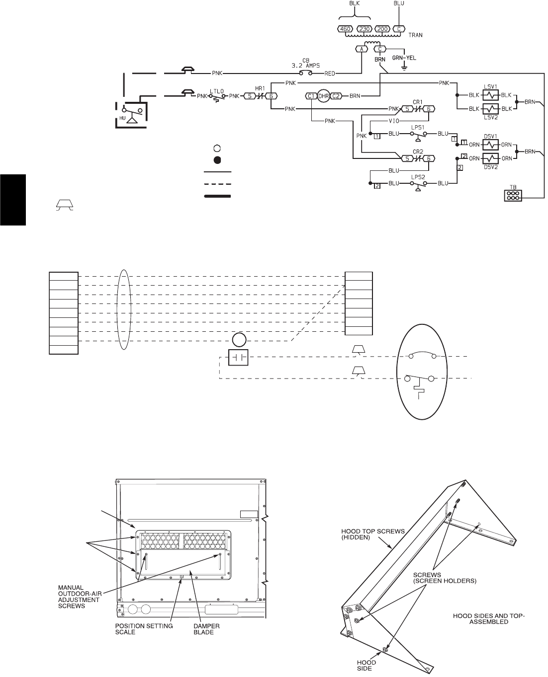
30
CB — Circuit Breaker
CR — Cooling Relay
DHR — Dehumidify Relay
DSV — Discharge Solenoid Valve
HR — Heater Relay
LPS — Low Pressure Switch
LSV — Liquid Solenoid Valve
LTLO — Low Temperature Lockout
Field Splice
Terminal (Unmarked)
Splice
Factory Wiring
Field Control Wiring
Field Power Wiring
LEGEND
C06128
Fig. 16 --- Typical Humidi--MiZertAdaptive Dehumidification System
Humidistat Wiring (208/230--V Unit Shown)
ROOF TOP UNIT
R
C
Y1
Y2
G
W1
W2
PINK
PINK
RED 24 V
FROM
HUMIDI-MIZER SYSTEM
LLSV
R1
TSTAT WIRES
LCT
R
C
Y1
Y2
G
W1
W2
DEHUM
OC
R1
HUMIDI-MIZER SYSTEM
PINK
LTLO
CB
3.2 AMPS
LEGEND
CB — Circuit Breaker
LCT — Light Commercial Thermidistat™ Device
LLSV — Liquid Line Solenoid Valve
LTLO — Low Temperature Lockout
C06129
Fig. 17 --- Typical Rooftop Unit with Humidi--Mizer
Adaptive Dehumidification System with Thermidistat Device
OUTDOOR
AIR OPENING
PANEL
3 SCREWS
(SIDE)
C06130
Fig. 18 --- Damper Panel with Manual Outdoor--Air
Damper Installed
C06013
Fig. 19 --- Outdoor--Air Hood Details
50HE,HJ
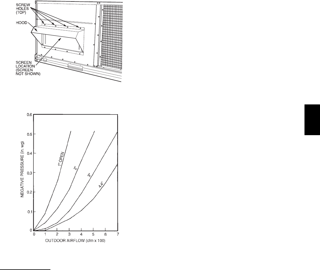
31
C06131
Fig. 20 --- Outdoor--Air Damper With
Hood Attached
C06132
Fig. 21 --- Outdoor--Air Damper Position Setting
PremierlinkControl
The PremierLink controller is compatible with Carrier Comfort
NetworkR(CCN) devices. This control is designed to allow
users the access and ability to change factory--defined settings,
thus expanding the function of the standard unit control board.
Carrier’s diagnostic standard tier display tools such as
Navigatortor Scrolling Marquee can be used with the
PremierLink controller.
The PremierLink controller (see Fig. 22 and 23) requires the use
of a Carrier electronic thermostat or a CCN connection for time
broadcast to initiate its internal timeclock. This is necessary for
broadcast of time of day functions (occupied/unoccupied). No
sensors are supplied with the field--mounted PremierLink control.
The factory--installed PremierLink control includes only the
supply--air temperature (SAT) sensor and the outdoor air
temperature (OAT) sensor as standard. An indoor air quality
(CO2) sensor can be added as an option. Refer to Table 5 for
sensor usage. Refer to Fig. 24 for PremierLink controller wiring.
The PremierLink control may be mounted in the control panel or
an area below the control panel.
NOTE: PremierLink controller versions 1.3 and later are shipped
in Sensor mode. If used with a thermostat, the PremierLink
controller must be configured to Thermostat mode.
Install the Supply Air Temperature (SAT) Sensor
When the unit is supplied with a factory--mounted PremierLink
control, the supply--air temperature (SAT) sensor
(33ZCSENSAT) is factory--supplied and wired. The wiring is
routed from the PremierLink control over the control box,
through a grommet, into the fan section, down along the back
side of the fan, and along the fan deck over to the supply--air
opening.
The SAT probe is wire--tied to the supply--air opening (on the
horizontal opening end) in its shipping position. Remove the
sensor for installation. Re--position the sensor in the flange of the
supply--air opening or in the supply air duct (as required by local
codes). Drill or punch a 1/2--in. hole in the flange or duct. Use
two field--supplied, self--drilling screws to secure the sensor probe
in a horizontal orientation.
NOTE: The sensor must be mounted in the discharge airstream
downstream of the cooling coil and any heating devices. Be sure
the probe tip does not come in contact with any of the unit or heat
surfaces.
Outdoor Air Temperature Sensor (OAT)
When the unit is supplied with a factory-mounted PremierLink
control, the outdoor-air temperature sensor (OAT) is
factory-supplied and wired.
Install the Indoor Air Quality (CO2)Sensor
Mount the optional indoor air quality (CO2) sensor according to
manufacturer specifications.
A separate field-supplied transformer must be used to power the
CO2sensor.
Wire the CO2sensor to the COM and IAQI terminals of J5 on the
PremierLink controller. Refer to the PremierLink Installation,
Start-up, and Configuration Instructions for detailed wiring and
configuration information.
Enthalpy Sensors and Control
The enthalpy control (HH57AC077) is supplied as a
field-installed accessory to be used with the EconoMi$er2
damper control option. The outdoor air enthalpy sensor is part of
the enthalpy control. The separate field-installed accessory return
air enthalpy sensor (HH57AC078) is required for differential
enthalpy control.
NOTE: The enthalpy control must be set to the “D” setting for
differential enthalpy control to work properly.
The enthalpy control receives the indoor and return
enthalpy from the outdoor and return air enthalpy sensors and
provides a dry contact switch input to the PremierLink controller.
Locate the controller in place of an existing economizer controller
or near the actuator. The mounting plate may not be needed if
existing bracket is used.
A closed contact indicates that outside air is preferred to the
return air. An open contact indicates that the economizer should
remain at minimum position.
Outdoor Air Enthalphy Sensor/Enthalpy Controller
(HH57AC077)
To wire the outdoor air enthalpy sensor, perform the following (See
Fig. 25 and 26):
NOTE: The outdoor air sensor can be removed from the back of
the enthalpy controller and mounted remotely.
50HE,HJ
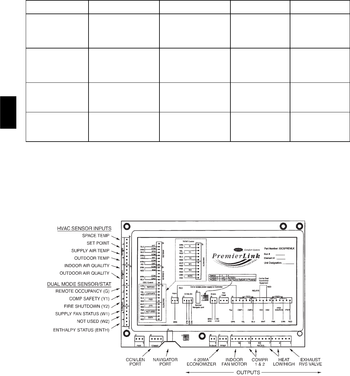
32
Table 5—PremierLinkSensor Usage
APPLICATION OUTDOOR AIR
TEMPERATURE SENSOR
RETURN AIR
TEMPERATURE SENSOR
OUTDOOR AIR
ENTHALPY SENSOR
RETURN AIR
ENTHALPY SENSOR
Dry Bulb
Te m pe r a tu r e w i th
PremierLink*
(PremierLink
requires 4-20 mA
Actuator)
I n c l u d e d ---
CRTEMPSN001A00 —— —
Differential Dry Bulb
Te m pe r a tu r e w i th
PremierLink*
(PremierLink
requires 4-20 mA
Actuator)
I n c l u d e d ---
CRTEMPSN001A00
R e q u i r e d ---
33ZCT55SPT
or Equivalent — —
Single Enthalpy with
PremierLink*
(PremierLink
requires 4-20 mA
Actuator)
I n c l u d e d ---
Not Used —
R e q u i r e d ---
HH57AC077
or Equivalent —
Differential Enthalpy
with PremierLink*
(PremierLink
requires 4-20 mA
Actuator)
I n c l u d e d ---
Not Used —
R e q u i r e d ---
HH57AC077
or Equivalent
R e q u i r e d ---
HH57AC078
or Equivalent
*PremierLink control requires Supply Air Temperature sensor 33ZCSENSAT and Outdoor Air Temperature sensor CRTEMPSN001A00
— Included with factory-installed PremierLink control; field-supplied and field-installed with field-installed PremierLink control.
NOTES:
1. CO2Sensors (Optional):
33ZCSENCO2 — Room sensor (adjustable). Aspirator box is required for duct mounting of the sensor.
33ZCASPCO2 — Aspirator box used for duct-mounted CO2room sensor.
33ZCT55CO2 — Space temperature and CO2room sensor with override.
33ZCT56CO2 — Space temperature and CO2room sensor with override and set point.
2. All units include the following Standard Sensors:
Outdoor-Air Sensor — 50HJ540569 — Opens at 67_F, c l o s e s a t 5 2 _F, not adjustable.
Mixed-Air Sensor — HH97AZ001 — (PremierLink control requires Supply Air Temperature sensor 33ZCSENSAT
and Outdoor Air Temperature Sensor CRTEMPSN001A00)
Compressor Lockout Sensor — 50HJ540570 — Opens at 35_F, c l o s e s a t 5 0 _F.
C06016
Fig. 22 --- PremierLink Controller
50HE,HJ
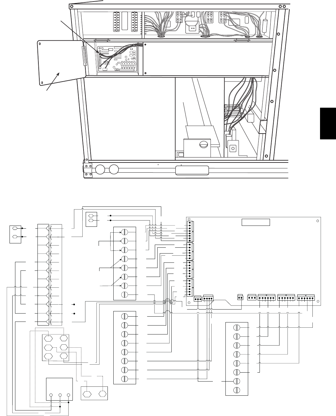
33
PREMIERLINK
CONTROL
HINGED
DOOR
PANEL
C06017
Fig. 23 --- PremierLinktController (Installed)
TB-1
R
Y1
Y2
W1
W2
G
C
X
1
2
3
4
5
6
7
8
TB-3
1
2
3
4
5
6
7
8
TB-2
1
2
3
4
5
6
7
8
J6
ANAL OG
J5
0-20mAIN
J4
DISCRETE
J1
PWR
J2
COMMS
J9
0-20 mA
J8
Relays
HK50AA039
BRN
BRN WHT
WHT
RED
PNK
PNK
ORNORN
ORN
ORN
GRA
GRA
ORN
RED
J7
PP/MP
WHT
BLK
RED
RED
PNK
WHT
BLK
PNK
WHT
BLU
ORN
YEL
GRN
BRN
BRN
RED
RED
BRN
BRN
BLK
BLK
BRN
BRN
BLU
BLU
1
2
3
4
5
6
7
8
9
10
11
12
1
2
3
4
5
6
7
8
9
10
11
12
PNK
PNK
VIO
VIO
GRA
ORN
PNK
PNK
GRA
GRA
GRA
SAT
BRN
ORN
BLK
RED
Space Temp./ Set
Point Adjustment
Indoor Air
Quality Sensor
OAT
PNK
VIO
YEL
YEL
BLU
BLU
Economi$er2
4 - 20mA
BLK
RED
WHT
PremierLink
GRN
YEL
BLU
BLU
BLU
Outdoor Air
Quality Sensor
Power Exhaust/Energy Recycler
CCN
Comm.
RMTOCC
SFS
CMPSAFE
FSD
RTU Terminal
Board
TR TR1
SR
23
+
+
S
RED
BRN
BLK
RED
GRAY
GRAY
OUTDOOR AIR
ENTHALPY SENSOR
RETURN AIR
ENTHALPY
SENSOR
LEGEND
COMMS — Communications
OAT — Outdoor Air Temperature Sensor
PWR — Power
RTU — Rooftop Unit
SAT — Supply Air Temperature Sensor
TB — Terminal Block
C06018
Fig. 24 --- Typical PremierLink Control Wiring
50HE,HJ
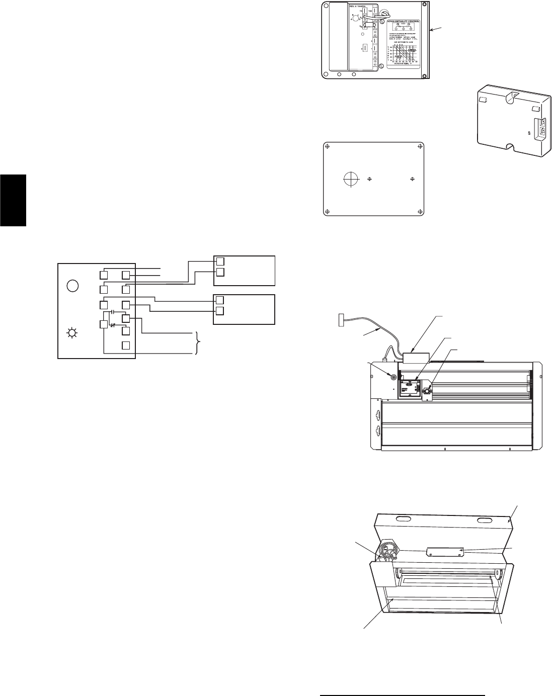
34
1. Use a 4-conductor, 18 or 20 AWG cable to connect the
enthalpy control to the PremierLinkcontroller and
power transformer.
2. Connect the following 4 wires from the wire harness
located in rooftop unit to the enthalpy controller:
a. Connect the BRN wire to the 24 vac terminal (TR1) on
enthalpy control and to pin 1 on 12-pin harness.
b. Connect the RED wire to the 24 vac GND terminal (TR)
on enthalpy sensor and to pin 4 on 12-pin harness.
c. Connect the GRAY/ORN wire to J4-2 on PremierLink
controller and to terminal (3) on enthalpy sensor.
d. Connect the GRAY/RED wire to J4-1 on PremierLink
controller and to terminal (2) on enthalpy sensor.
NOTE: If installing in a Carrier rooftop, use the two gray wires
provided from the control section to the economizer to connect
PremierLinkcontrollertoterminals2and3onenthalpysensor.
Return Air Enthalphy Sensor
Mount the return-air enthalpy sensor (HH57AC078) in the
return-air duct. The return air sensor is wired to the enthalpy
controller (HH57AC077). The outdoor enthalpy changeover set
point is set at the controller.
LED
ABC
D
TR TR1
SO
SR
2
3
1
+
+
BRN
RED
GRAY/ORN
GRAY/RED
WIRE HARNESS
IN UNIT
BLK
RED
S
+
(RETURN AIR
ENTHALPY
SENSOR)
S
+
(OUTDOOR
AIR
ENTHALPY
SENSOR)
ENTHALPY CONTROLLER
NOTES:
1. Remove factory-installed jumper across SR and + before connecting
wires from return air sensor.
2. Switches shown in high outdoor air enthalpy state. Terminals 2 and 3
close on low outdoor air enthalpy relative to indoor air enthalpy.
3. Remove sensor mounted on back of control and locate in outside air-
stream.
C06019
Fig. 25 --- Outdoor and Return Air Sensor Wiring
Connections for Differential Enthalpy Control
To wire the return air enthalpy sensor, perform the following (See
Fig. 25):
1. Use a 2--conductor, 18 or 20 AWG, twisted pair cable to
connect the return air enthalpy sensor to the enthalpy
controller.
2. At the enthalpy control remove the factory-installed
resistor from the (SR) and (+) terminals.
3. Connect the field-supplied RED wire to (+) spade
connector on the return air enthalpy sensor and the (SR+)
terminal on the enthalpy controller. Connect the BLK wire
to (S) spade connector on the return air enthalpy sensor
and the (SR) terminal on the enthalpy controller.
BRACKET
+
C7400A1004
HH57AC077
ENTHALPY
CONTROL AND
OUTDOOR AIR
ENTHALPY SENSOR
HH57AC078 ENTHALPY
SENSOR (USED WITH
ENTHALPY CONTROL
FOR DIFFERENTIAL
ENTHALPY OPERATION)
MOUNTING PLATE
C06020
Fig. 26 --- Differential Enthalpy Control,
Sensor and Mounting Plate (33AMKITENT006)
ECONOMI$ER IV
CONTROLLER
OUTSIDE AIR
TEMPERATURE SENSOR
LOW AMBIENT
SENSOR
A
CTUATOR
WIRING
HARNESS
C06021
Fig. 27 --- EconoMi$er IV Component Locations
ECONOMI$ER2
PLUG
BAROMETRIC
RELIEF
DAMPER
OUTDOOR
AIR HOOD
HOOD
SHIPPING
BRACKET
GEAR DRIVEN
DAMPER
C06022
Fig. 28 --- EconoMi$er2 Component Locations
Optional Economi$er IV and Economi$er2
See Fig. 27 for EconoMi$er IV component locations. See Fig. 28 for
EconoMi$er2 component locations.
50HE,HJ
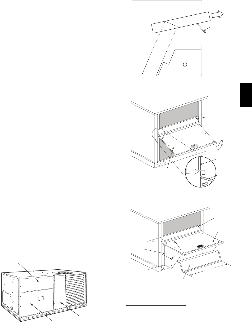
35
NOTE: These instructions are for installing the optional
EconoMi$er IV and EconoMi$er2 only. Refer to the accessory
EconoMi$er IV or EconoMi$er2 installation instructions when
field installing an EconoMi$er IV or EconoMi$er2 accessory.
1. To remove the existing unit filter access panel, raise the
panel and swing the bottom outward. The panel is now
disengaged from the track and can be removed. (See
Fig. 29.)
2. The box with the economizer hood components is shipped
in the compartment behind the economizer. The
EconoMi$er IV controller is mounted on top of the
EconoMi$er IV in the position shown in Fig. 24. The
optional EconoMi$er2 with 4 to 20 mA actuator signal
control does not include the EconoMi$er IV controller. To
remove the component box from its shipping position,
remove the screw holding the hood box bracket to the top
of the economizer. Slide the hood box out of the unit. (See
Fig. 30.)
IMPORTANT: If the power exhaust accessory is to be installed
on the unit, the hood shipped with the unit will not be used and
must be discarded. Save the aluminum filter for use in the power
exhaust hood assembly.
3. The indoor coil access panel will be used as the top of the
hood. Remove the screws along the sides and bottom of
the indoor coil access panel. (See Fig. 31.)
4. Swing out indoor coil access panel and insert the hood
sides under the panel (hood top). Use the screws provided
to attach the hood sides to the hood top. Use screws
provided to attach the hood sides to the unit. (See Fig. 32.)
5. Remove the shipping tape holding the economizer
barometric relief damper in place.
6. Insert the hood divider between the hood sides. (See
Fig. 32 and 33.) Secure hood divider with 2 screws on
each hood side. The hood divider is also used as the
bottom filter rack for the aluminum filter.
7. Open the filter clips which are located underneath the
hood top. Insert the aluminum filter into the bottom filter
rack (hood divider). Push the filter into position past the
open filter clips. Close the filter clips to lock the filter into
place. (See Fig. 33.)
8. Caulk the ends of the joint between the unit top panel and
the hood top. (See Fig. 31.)
9. Replace the filter access panel.
10. Install all EconoMi$er IV accessories. EconoMi$er IV
wiring is shown in Fig. 34. EconoMi$er2 wiring is shown
in Fig. 35.
Barometric flow capacity is shown in Fig. 36. Outdoor air
leakage is shown in Fig. 37. Return air pressure drop is shown in
Fig. 38.
FILTER ACCESS PANEL
OUTDOOR-AIR OPENING AND
INDOOR COIL ACCESS PANEL
COMPRESSOR
ACCESS PANEL
C06023
Fig. 29 --- Typical Access Panel Locations
HoodBox
HOOD BOX
BRACKET
C06024
Fig. 30 --- Hood Box Removal
SIDE
PANEL
INDOOR
COIL
ACCESS
PANEL
INDOOR
COIL
ACCESS
PANEL
CAULK
HERE
TOP
SIDE
PANEL
C06025
Fig. 31 --- Indoor Coil Access Panel Relocation
B
TOP
PANEL
INDOOR COIL
ACCESS PANEL
19 1/16”
SCREW
HOOD DIVIDER
LEFT
HOOD
SIDE
33 3/8”
C06026
Fig. 32 --- Outdoor--Air Hood Construction
Economi$er IV Standard Sensors
Outdoor Air Temperature (OAT) Sensor
The outdoor air temperature sensor (HH57AC074) is a 10 to 20 mA
device used to measure the outdoor-air temperature. The outdoor-air
temperature is used to determine when the EconoMi$er IV can be
used for free cooling. The sensor is factory-installed on the
EconoMi$er IV in the outdoor airstream. (See Fig. 27.) The
operating range of temperature measurement is 40_to 100_F.
50HE,HJ
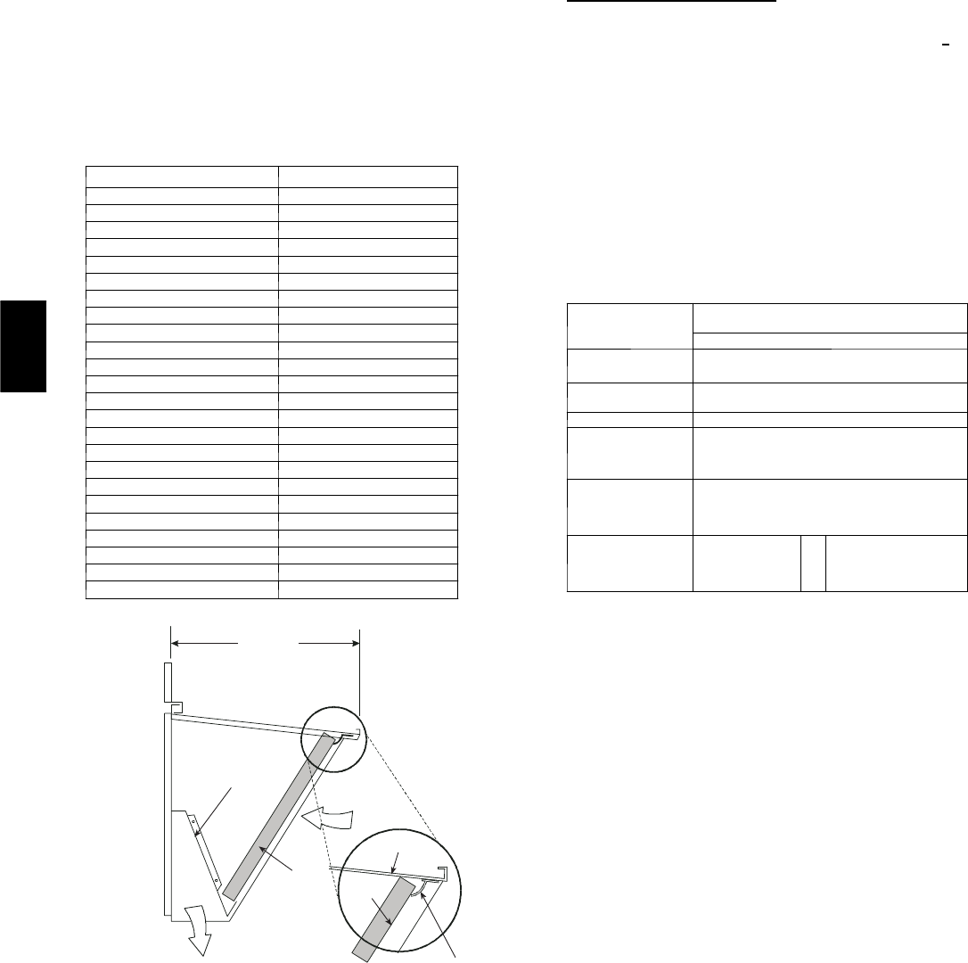
36
Supply Air Temperature (SAT) Sensor
The supply air temperature sensor is a 3 K thermistor located at
the inlet of the indoor fan. (See Fig. 39.) This sensor is factory
installed. The operating range of temperature measurement is 0
to 158_F. See Table 6 for sensor temperature/resistance values.
Table 6—Supply Air Sensor Temperature/
Resistance Values
TEMPERATURE (F) RESISTANCE (ohms)
–58 200,250
–40 100,680
–22 53,010
–4 29,091
14 16,590
32 9,795
50 5,970
68 3,747
77 3,000
86 2,416
104 1,597
122 1,080
140 746
158 525
176 376
185 321
194 274
212 203
230 153
248 116
257 102
266 89
284 70
302 55
17 1/4”
DIVIDER
BAROMETRIC
RELIEF
CLEANABLE
ALUMINUM
FILTER FILTER
HOOD
FILTE
R
CLIP
OUTSIDE
AIR
C06027
Fig. 33 --- Filter Installation
The temperature sensor looks like an eyelet terminal with wires
running to it. The sensor is located in the “crimp end” and is
sealed from moisture.
Outdoor Air Lockout Sensor
The Economi$er IV is equipped with an ambient temperature
lockout switch located in the outdoor air stream which is used to
lockout the compressors below a 42_F ambient temperature. (See
Fig. 27.)
Economi$er IV Control Modes
IMPORTANT: The optional EconoMi$er2 does not include a
controller. The EconoMi$er2 is operated by a 4 to 20 mA signal
from an existing field-supplied controller (such as PremierLink
control). See Fig. 35 for wiring information.
Determine the EconoMi$er IV control mode before set up of the
control. Some modes of operation may require different
sensors. Refer to Table 7. The EconoMi$er IV is supplied from
the factory with a supply--air temperature sensor and an outdoor--
air temperature sensor. This allows for operation of the
EconoMi$er IV with outdoor air dry bulb changeover control.
Additional accessories can be added to allow for different types of
changeover control and operation of the EconoMi$er IV and unit.
Table7—Economi$erIVSensorUsage
APPLICATION
ECONOMI$ER IV WITH OUTDOOR AIR
DRY BULB SENSOR
Accessories Required
Outdoor Air
Dry Bulb
None. The outdoor air dry bulb sensor
is factory installed.
Differential
Dry Bulb CRTEMPSN002A00*
Single Enthalpy HH57AC078
Differential
Enthalpy
HH57AC078
and
CRENTDIF004A00*
CO2for DCV
Control using a
Wall-Mounted
CO2Sensor
33ZCSENCO2
CO2for DCV
Control using a
Duct-Mounted
CO2Sensor
33ZCSENCO2†
and
33ZCASPCO2**
O
RCRCBDIOX005A00††
*CRENTDIF004A00 and CRTEMPSN002A00 accessories are used on many
different base units. As such, these kits may contain parts that will not be
needed for installation.
† 33ZCSENCO2 is an accessory CO2sensor.
** 33ZCASPCO2 is an accessory aspirator box required for duct-mounted
applications.
†† CRCBDIOX005A00 is an accessory that contains both 33ZCSENCO2
and 33ZCASPCO2 accessories.
Outdoor Dry Bulb Changeover
The standard controller is shipped from the factory configured for
outdoor dry bulb changeover control. The outdoor--air and
supply--air temperature sensors are included as standard. For this
control mode, the outdoor temperature is compared to an
adjustable set point selected on the control. If the outdoor-air
temperature is above the set point, the EconoMi$er IV will adjust
the outdoor-air dampers to minimum position. If the outdoor air
temperature is below the set point, the position of the outdoor air
dampers will be controlled to provide free cooling using outdoor
air. When in this mode, the LED next to the free cooling set point
potentiometer will be on. The changeover temperature set point is
controlled by the free cooling set point potentiometer located on
the control. (See Fig. 40.) The scale on the potentiometer is A, B,
C, and D. See Fig. 41 for the corresponding temperature
changeover values.
Differential Dry Bulb Control
For differential dry bulb control the standard outdoor dry bulb
sensor is used in conjunction with an additional accessory dry
bulb sensor (part number CRTEMPSN002A00). The accessory
sensor must be mounted in the return airstream. (See Fig. 42.)
Wiring is provided in the EconoMi$er IV wiring harness. (See
Fig. 33.)
In this mode of operation, the outdoor-air temperature is
compared to the return-air temperature and the lower temperature
airstream is used for cooling. When using this mode of
changeover control, turn the enthalpy setpoint potentiometer fully
clockwise to the D setting. (See Fig. 40.)
50HE,HJ
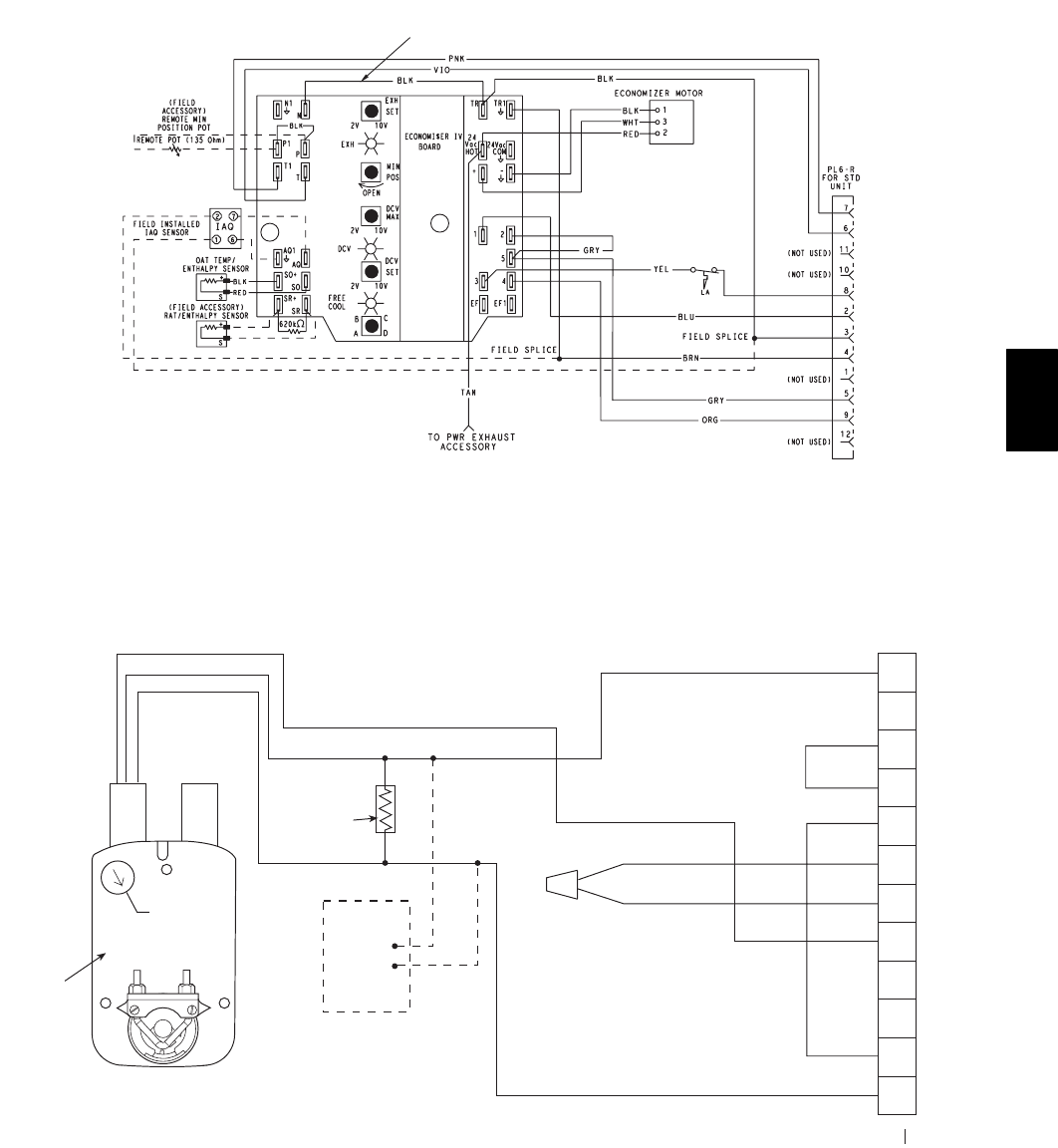
37
FOR OCCUPANCY CONTROL
REPLACE JUMPER WITH
FIELD-SUPPLIED TIME CLOCK
LEGEND
DCV— Demand Controlled Ventilation
IAQ — Indoor Air Quality
LA — Low Ambient Lockout Device
OAT — Outdoor-Air Temperature
POT — Potentiometer
RAT — Return-Air Temperature
Potentiometer Defaults Settings:
Power Exhaust Middle
Minimum Pos. Fully Closed
DCV Max. Middle
DCV Set Middle
Enthalpy C Setting
NOTES:
1. 620 ohm, 1 watt 5% resistor should be removed only when using differential
enthalpy or dry bulb.
2. If a separate field-supplied 24 v transformer is used for the IAQ sensor power
supply, it cannot have the secondary of the transformer grounded.
3. For field-installed remote minimum position POT, remove black wire jumper
between P and P1 and set control minimum position POT to the minimum
p
osition.
C06028
Fig. 34 --- EconoMi$er IV Wiring
4
3
5
2
8
6
7
1
10
11
9
12
PINK
VIOLET
BLACK
BLUE
YELLOW
NOTE 1
NOTE 3
RUN
500 OHM
RESISTOR
-
+
OPTIONAL CO
SENSOR4-20mA
OUTPUT
50HJ540573
ACTUATOR
ASSEMBLY
RED
WHITE
ECONOMISER2 PLUG
DIRECT DRIVE
ACTUATOR
2
NOTES:
1. Switch on actuator must be in run position for economizer to operate.
2. PremierLink™ control requires that the standard 50HJ540569 outside-air sensor be replaced by either the CROASENR001A00 dry bulb sensor or HH57A077
enthalpy sensor.
3. 50HJ540573 actuator consists of the 50HJ540567 actuator and a harness with 500-ohm resistor.
C06029
Fig. 35 --- EconoMi$er2 with 4 to 20 mA Control Wiring
Outdoor Enthalpy Changeover
For enthalpy control, accessory enthalpy sensor (part number
HH57AC078) is required. Replace the standard outdoor dry bulb
temperature sensor with the accessory enthalpy sensor in the same
mounting location. (See Fig. 27.) When the outdoor air enthalpy
rises above the outdoor enthalpy changeover set point, the
outdoor-air damper moves to its minimum position. The outdoor
enthalpy changeover set point is set with the outdoor enthalpy set
point potentiometer on the EconoMi$er IV controller. The set
points are A, B, C, and D. (See Fig. 43.) The factory-installed
620-ohm jumper must be in place across terminals SR and SR+
on the EconoMi$er IV controller. (See Fig. 27 and 44.)
50HE,HJ
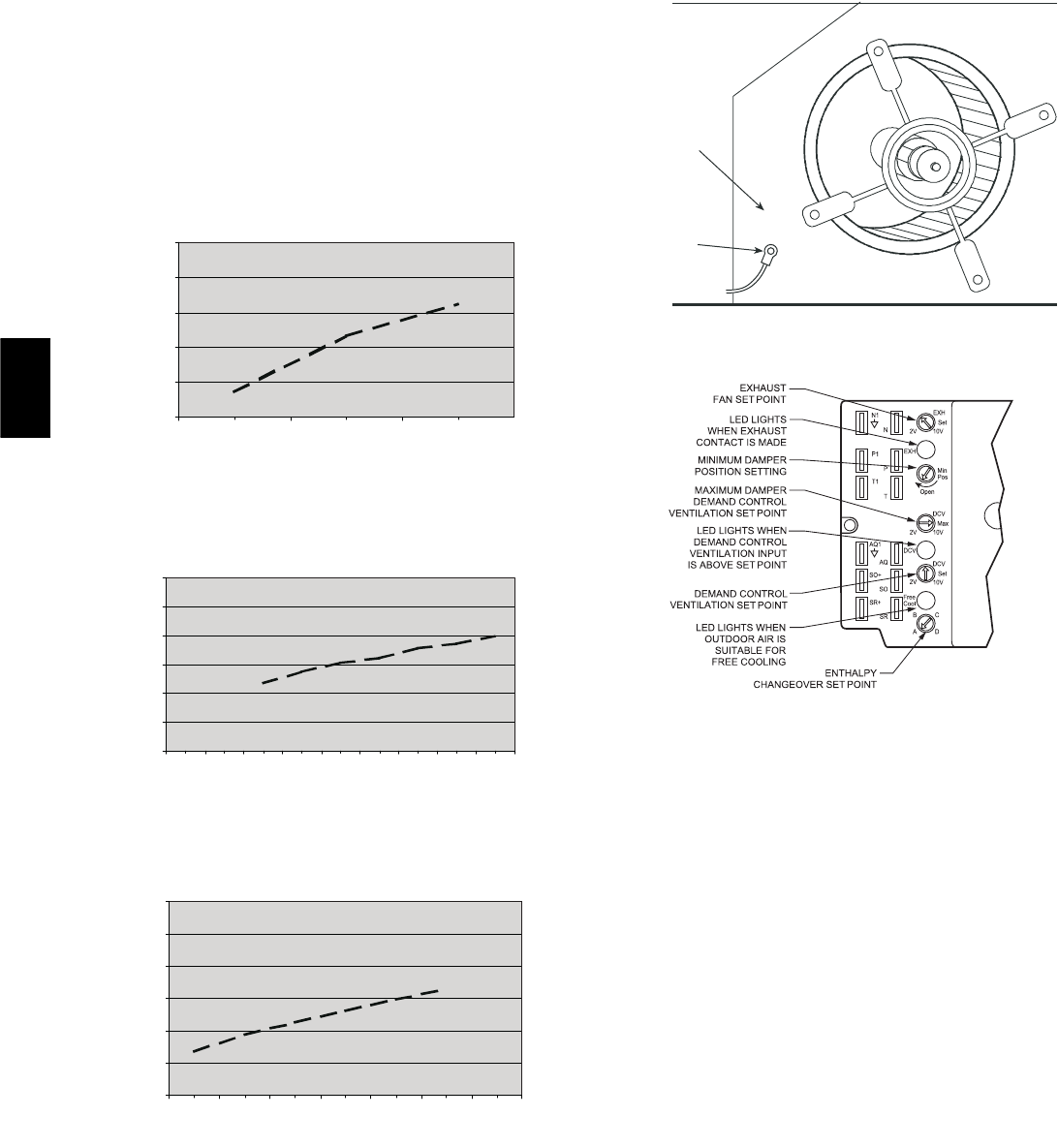
38
Differential Enthalphy Control
For differential enthalpy control, the EconoMi$er IV controller
uses two enthalpy sensors (HH57AC078 and
CRENTDIF004A00), one in the outside air and one in the return
air duct. The EconoMi$er IV controller compares the outdoor
air enthalpy to the return air enthalpy to determine EconoMi$er
IV use. The controller selects the lower enthalpy air (return or
outdoor) for cooling. For example, when the outdoor air has a
lower enthalpy than the return air, the EconoMi$er IV opens to
bring in outdoor air for free cooling.
0
500
1000
1500
2000
2500
0.05 0.15 0.25
STATIC PRESSURE (in. wg)
FLOW IN CUBIC FEET PER MINUTE (cfm)
C06030
Fig. 36 --- Barometric Flow Capacity
0
5
10
15
20
25
30
0.13 0.20 0.22 0.25 0.30 0.35 0.40 0.45 0.50
STATIC PRESSURE (in. wg)
FLOW IN CUBIC FEET PER MINUTE (cfm)
C06031
Fig. 37 --- Outdoor--Air Damper Leakage
0
1000
2000
3000
4000
5000
6000
0.05 0.10 0.15 0.20 0.25 0.30 0.35
STATIC PRESSURE (in. wg)
FLOW IN CUBIC FEET PER MINUTE (cfm)
C06032
Fig. 38 --- Return--Air Pressure Drop
SUPPLY AIR
TEMPERATURE
SENSOR
MOUNTING
LOCATION
SUPPLY AIR
TEMPERATURE
SENSOR
C06033
Fig. 39 --- Supply Air Sensor Location
C06034
Fig. 40 --- EconoMi$er IV Controller Potentiometer
and LED Locations
Replace the standard outside air dry bulb temperature sensor with
the accessory enthalpy sensor in the same mounting location.
(See Fig. 27.) Mount the return air enthalpy sensor in the return
air duct. (See Fig. 42.) Wiring is provided in the EconoMi$er IV
wiring harness. (See Fig. 34.) The outdoor enthalpy changeover
set point is set with the outdoor enthalpy set point potentiometer
on the EconoMi$er IV controller. When using this mode of
changeover control, turn the enthalpy setpoint potentiometer fully
clockwise to the D setting.
Indoor Air Quality (IAQ) Sensor Input
The IAQ input can be used for demand control ventilation control
based on the level of CO2measured in the space or return air
duct.
Mount the accessory IAQ sensor according to manufacturer
specifications. The IAQ sensor should be wired to the AQ and
AQ1 terminals of the controller. Adjust the DCV potentiometers
to correspond to the DCV voltage output of the indoor air quality
sensor at the user-determined set point. (See Fig. 45.)
If a separate field-supplied transformer is used to power the IAQ
sensor, the sensor must not be grounded or the EconoMi$er IV
control board will be damaged.
Exhaust Set Point Adjustment
The exhaust set point will determine when the exhaust fan runs
based on damper position (if accessory power exhaust is
installed). The set point is modified with the Exhaust Fan Set
Point (EXH SET) potentiometer. (See Fig. 40.) The set point
represents the damper position above which the exhaust fans will
be turned on. When there is a call for exhaust, the EconoMi$er IV
controller provides a 45 15 second delay before exhaust fan
50HE,HJ
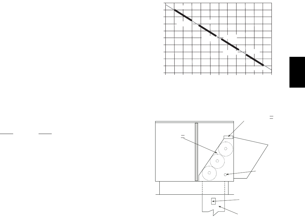
39
activation to allow the dampers to open. This delay allows the
damper to reach the appropriate position to avoid unnecessary fan
overload.
Minimum Position Control
There is a minimum damper position potentiometer on the
EconoMi$er IV controller. (See Fig. 40.) The minimum damper
position maintains the minimum airflow into the building during
the occupied period.
When using demand ventilation, the minimum damper position
represents the minimum ventilation position for VOC (volatile
organic compound) ventilation requirements. The maximum
demand ventilation position is used for fully occupied ventilation.
When demand ventilation control is not being used, the minimum
position potentiometer should be used to set the occupied
ventilation position. The maximum demand ventilation position
should be turned fully clockwise.
Adjust the minimum position potentiometer to allow the
minimum amount of outdoor air, as required by local codes, to
enter the building. Make minimum position adjustments with at
least 10_F temperature difference between the outdoor and
return-air temperatures.
To determine the minimum position setting, perform the
following procedure:
1. Calculate the appropriate mixed air temperature using the
following formula:
(TOx
OA )+(TRxRA )=T
M
100 100
TO= Outdoor-Air Temperature
OA = Percent of Outdoor Air
TR= Return-Air Temperature
RA = Percent of Return Air
TM= Mixed-Air Temperature
As an example, if local codes require 10% outdoor air during
occupied conditions, outdoor-air temperature is 60_F, and
return-air temperature is 75_F.
(60 x .10) + (75 x .90) = 73.5_F
2. Disconnect the supply air sensor from terminals T and T1.
3. Ensure that the factory-installed jumper is in place across
terminals P and P1. If remote damper positioning is being
used, make sure that the terminals are wired according to
Fig. 34 and that the minimum position potentiometer is
turned fully clockwise.
4. Connect 24 vac across terminals TR and TR1.
5. Carefully adjust the minimum position potentiometer
until the measured supply air temperature matches the
calculated value.
6. Reconnect the mixed air sensor to terminals T and T1.
Remote control of the EconoMi$er IV damper is desirable when
requiring additional temporary ventilation. If a
field-supplied remote potentiometer (Honeywell part number
S963B1128) is wired to the EconoMi$er IV controller, the
minimum position of the damper can be controlled from a remote
location.
To control the minimum damper position remotely, remove the
factory-installed jumper on the P and P1 terminals on the
EconoMi$er IV controller. Wire the field-supplied potentiometer
to the P and P1 terminals on the EconoMi$er IV controller. (See
Fig. 44.)
Damper Movement
Damper movement from full open to full closed (or vice versa)
takes 21/2minutes.
Thermostats
The EconoMi$er IV control works with conventional thermostats
that have a Y1 (cool stage 1), Y2 (cool stage 2), W1 (heat stage
1), W2 (heat stage 2), and G (fan). The EconoMi$er IV control
does not support space temperature sensors. Connections are
made at the thermostat terminal connection board located in the
main control box.
LED ON
LED ON
LED ON
LED ON
LED OFF
19
18
LED OFF
LED OFF
LED OFF
17
16
15
14
13
12
11
10
9
40 45 50 55 60 65 70 75 80 85 90 95 100
DEGREES FAHRENHEIT
mA
D
C
B
A
C06035
Fig. 41 --- Outside Air Temperature
Changeover Set Points
ECONOMI$ER IV
ECONOMI$ER IV
CONTROLLER
GROMMET
RETURN AIR
SENSOR
RETURN DUCT
(FIELD-PROVIDED)
C06036
Fig. 42 --- Return Air Temperature or Enthalpy
Sensor Mounting Location
Occupancy Control
The factory default configuration for the EconoMi$er IV control
is occupied mode. Occupied mode is provided by the black
jumper from terminal TR to terminal N. When unoccupied mode
is desired, install a field-supplied timeclock function in place of
the jumper between TR and N. (See Fig. 34.) When the timeclock
contacts are closed, the EconoMi$er IV control will be in
occupied mode. When the timeclock contacts are open (removing
the 24-v signal from terminal N), the EconoMi$er IV will be in
unoccupied mode.
50HE,HJ
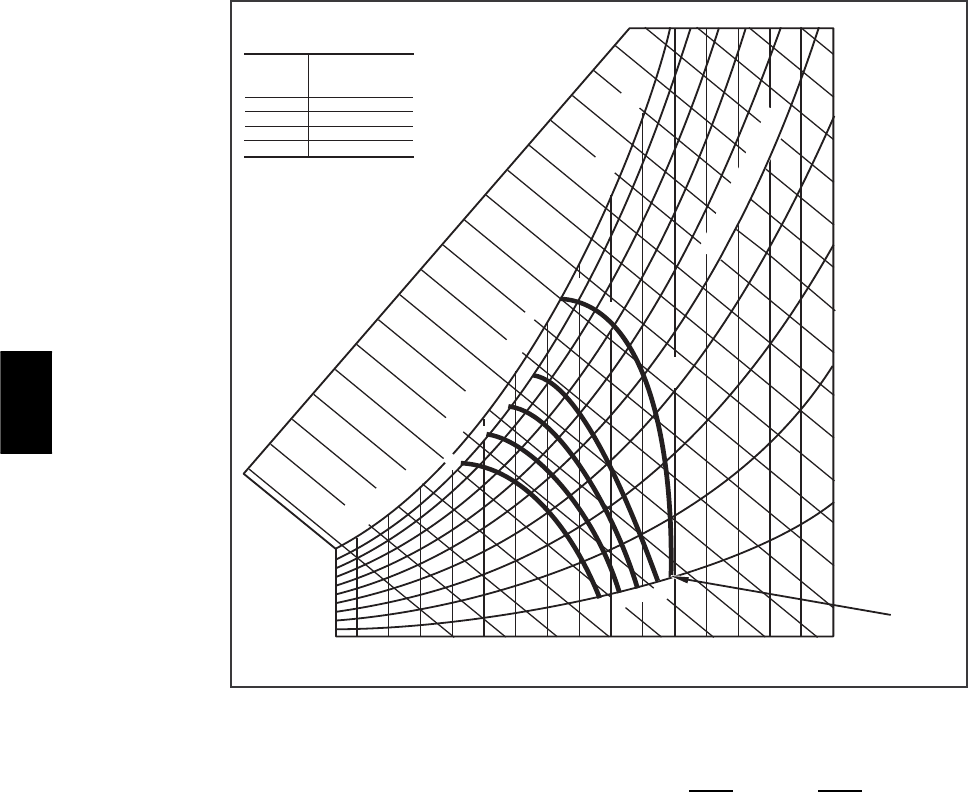
40
CONTROL
CURVE
A
B
C
D
CONTROL POINT
APPROX.
deg. F (deg. C)
AT 50% RH
73 (23)
70 (21)
67 (19)
63 (17)
12 14 16 18 20 22 24 26 28 30 32 34 36 38 40 42 44 46
90
100
80
70
60
50
40
30
20
10
ENTHALPY BTU PER POUND DRY AIR
85
(29) 90
(32) 95
(35) 100
(38) 105
(41) 110
(43)
35
(2)
35
(2)
40
(4)
40
(4)
105
(41) 110
(43)
45
(7)
45
(7)
50
(10)
50
(10)
55
(13)
55
(13)
60
(16)
60
(16)
65
(18)
65
(18)
70
(21)
70
(21)
75
(24)
75
(24)
80
(27)
80
(27)
85
(29) 90
(32) 95
(35) 100
(38)
A
A
B
B
C
C
D
D
RELATIVE HUMIDITY (%)
HIGH LIMIT
CURVE
APPROXIMATE DRY BULB TEMPERATURE--degrees F (degrees C)
C06037
Fig. 43 --- Enthalpy Changeover Set Points
Demand Controlled Ventilation (DCV)
When using the EconoMi$er IV for demand controlled
ventilation, there are some equipment selection criteria which
should be considered. When selecting the heat capacity and cool
capacity of the equipment, the maximum ventilation rate must be
evaluated for design conditions. The maximum damper position
must be calculated to provide the desired fresh air.
Typically the maximum ventilation rate will be about 5 to 10%
more than the typical cfm required per person, using normal
outside air design criteria.
A proportional anticipatory strategy should be taken with the
following conditions: a zone with a large area, varied occupancy,
and equipment that cannot exceed the required ventilation rate at
design conditions. Exceeding the required ventilation rate means
the equipment can condition air at a maximum ventilation rate
that is greater than the required ventilation rate for maximum
occupancy. A proportional-anticipatory strategy will cause the
fresh air supplied to increase as the room CO2level increases
even though the CO2set point has not been reached. By the time
the CO2level reaches the set point, the damper will be at
maximum ventilation and should maintain the set point.
In order to have the CO2sensor control the economizer damper in
this manner, first determine the damper voltage output for
minimum or base ventilation. Base ventilation is the ventilation
required to remove contaminants during unoccupied periods. The
following equation may be used to determine the percent of
outside-air entering the building for a given damper position. For
best results there should be at least a 10 degree difference in
outside and return-air temperatures.
(TOx
OA )+(TRxRA )=T
M
100 100
TO= Outdoor-Air Temperature
OA = Percent of Outdoor Air
TR= Return-Air Temperature
RA = Percent of Return Air
TM= Mixed-Air Temperature
Once base ventilation has been determined, set the minimum
damper position potentiometer to the correct position.
The same equation can be used to determine the occupied or
maximum ventilation rate to the building. For example, an output
of 3.6 volts to the actuator provides a base ventilation rate of 5%
and an output of 6.7 volts provides the maximum ventilation rate
of 20% (or base plus 15 cfm per person). Use Fig. 42 to
determine the maximum setting of the CO2sensor. For example,
a 1100 ppm set point relates to a 15 cfm per person design. Use
the 1100 ppm curve on Fig. 45 to find the point when the CO2
sensor output will be 6.7 volts. Line up the point on the graph
with the left side of the chart to determine that the range
configuration for the CO2sensor should be 1800 ppm. The
EconoMi$er IV controller will output the 6.7 volts from the CO2
sensor to the actuator when the CO2concentration in the space is
at 1100 ppm. The DCV set point may be left at 2 volts since the
CO2sensor voltage will be ignored by the EconoMi$er IV
controller until it rises above the 3.6 volt setting of the minimum
position potentiometer.
Once the fully occupied damper position has been determined, set
the maximum damper demand control ventilation potentiometer
to this position. Do not set to the maximum position as this can
result in over-ventilation to the space and potential high-humidity
levels.
50HE,HJ
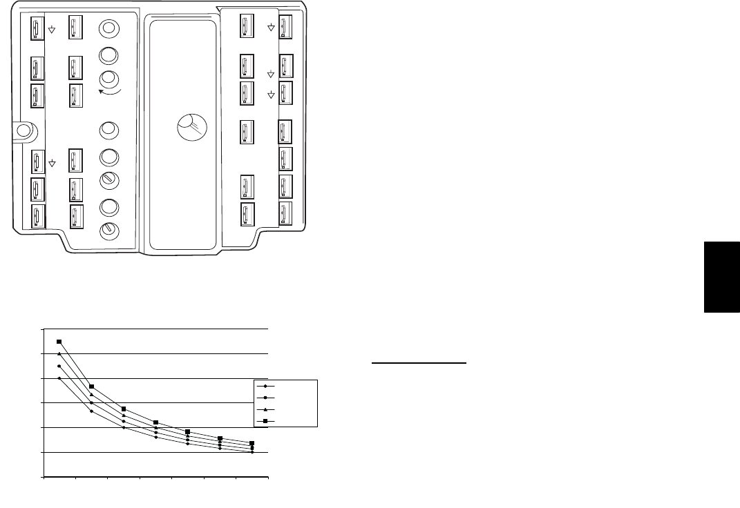
41
TR1
24 Vac
COM
TR
24
Vac
HOT
12
34
5
EF EF1
+_
P1
T1
P
T
N
EXH
2V 10V
EXH
Set
Set
2V 10V
2V 10V
DCV
DCV
Free
Cool
BC
AD
SO+
SR+
SR
SO
AQ1
AQ
DCV
Min
Pos
Open
Max
N1
C06038
Fig. 44 --- EconoMi$er IV Control
0
1000
2000
3000
4000
5000
6000
2345678
800 ppm
900 ppm
1000 ppm
1100 ppm
RANGE CONFIGURATION (ppm)
DAMPER VOLTAGE FOR MAX VENTILATION RATE
CO SENSOR MAX RANGE SETTING
2
C06039
Fig. 45 --- CO2Sensor Maximum Range Setting
CO2Sensor Configuration
The CO2sensor has preset standard voltage settings that can be
selected anytime after the sensor is powered up. (See Table 8.)
Use setting 1 or 2 for Carrier equipment. (See Table 8.)
1. Press Clear and Mode buttons. Hold at least 5 seconds
until the sensor enters the Edit mode.
2. Press Mode twice. The STDSET Menu will appear.
3. Use the Up/Down button to select the preset number. (See
Table 8.)
4. Press Enter to lock in the selection.
5. Press Mode to exit and resume normal operation.
The custom settings of the CO2sensor can be changed anytime
after the sensor is energized. Follow the steps below to change the
non-standard settings:
1. Press Clear and Mode buttons. Hold at least 5 seconds
until the sensor enters the Edit mode.
2. Press Mode twice. The STDSET Menu will appear.
3. Use the Up/Down button to toggle to the NONSTD menu
and press Enter.
4. Use the Up/Down button to toggle through each of the
nine variables, starting with Altitude, until the desired
setting is reached.
5. Press Mode to move through the variables.
6. Press Enter to lock in the selection, then press Mode to
continue to the next variable.
Dehumidification of Fresh Air with DCV Control
Information from ASHRAE indicates that the largest humidity
load on any zone is the fresh air introduced. For some
applications, a device such as a 62AQ energy recovery unit is
added to reduce the moisture content of the fresh air being
brought into the building when the enthalpy is high. In most
cases, the normal heating and cooling processes are more than
adequate to remove the humidity loads for most commercial
applications.
If normal rooftop heating and cooling operation is not adequate
for the outdoor humidity level, an energy recovery unit and/or a
dehumidification option should be considered.
Step 7 —Adjust Evaporator--Fan Speed
Adjust evaporator-fan speed to meet jobsite conditions.
Tables 9 and 10 show fan rpm at motor pulley settings for the
50HE003--006 and 50HJ004--007 units. Tables 11 and 14 show
maximum amp draw of belt-drive motor. Table 13 shows sound
data. Refer to Tables 15-34 for performance data. See Table 35
for accessory static pressure drop. See Fig. 47 for the
Humidi-MiZersystem static pressure drops.
For units with electric heating, required minimum cfm is 900 for
50HJ004; 1200 for 50HJ005; 1500 for 50HJ006 and 1800 for
50HJ007.
Belt Drive Motors
Fan motor pulleys are factory set for speed shown in Table 1.
Check pulley alignment and belt tension prior to start-up.
To change fan speed:
1. Shut off the unit power supply and tag disconnect.
2. Loosen the belt by loosening the fan motor mounting nuts.
(See Fig. 47.)
3. Loosen movable pulley flange setscrew (See Fig. 48).
4. Screw movable flange toward fixed flange to increase
speed and away from fixed flange to decrease speed.
Increasing fan speed increases load on motor. Do not
exceed maximum speed specified in Table 1.
5. Set movable flange at nearest keyway of pulley hub and
tighten setscrew. (See Table 1 for speed change for each
full turn of pulley flange.)
6. Adjust belt tension and align fan and motor pulleys per
guidance below.
NOTE: Once the required flange position is determined for the
correct blower rpm, it is recommended (but not required) that the
variable pitch pulley be replaced with a corresponding size fixed
sheave pulley.
To align fan and motor pulleys:
1. Loosen fan pulley setscrews.
2. Slide fan pulley along fan shaft.
3. Make angular alignment by loosening motor from mount-
ing.
To adjust belt tension:
1. Loosen fan motor mounting nuts.
2. Slide motor mounting plate away from fan scroll for
proper belt tension (1/2-in.deflectionwith7to10lbof
force).
3. Tighten motor mounting nuts.
4. Adjust bolt and tighten nut to secure motor in fixed
position.
50HE,HJ
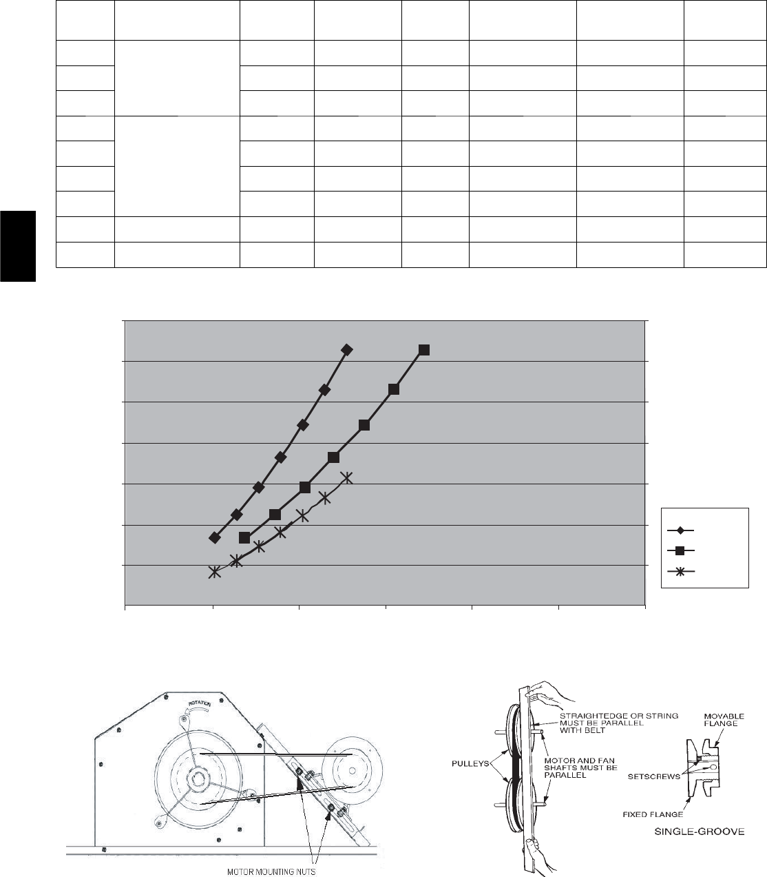
42
Table 8—CO2Sensor Standard Settings
SETTING EQUIPMENT OUTPUT
VENTILATION
RATE
(cfm/Person)
ANALOG
OUTPUT
CO2
CONTROL RANGE
(ppm)
OPTIONAL
RELAY SETPOINT
(ppm)
RELAY
HYSTERESIS
(ppm)
1
Interface w/Standard
Building Control System
Proportional Any 0-10V
4-20 mA 0-2000 1000 50
2Proportional Any 2-10V
7-20 mA 0-2000 1000 50
3Exponential Any 0-10V
4-20 mA 0-2000 1100 50
4
Economizer
Proportional 15 0-10V
4-20 mA 0-1100 1100 50
5Proportional 20 0-10V
4-20 mA 0- 900 900 50
6Exponential 15 0-10V
4-20 mA 0-1100 1100 50
7Exponential 20 0-10V
4-20 mA 0- 900 900 50
8Health & Safety Proportional —0-10V
4-20 mA 0-9999 5000 500
9Parking/Air Intakes/
Loading Docks Proportional —0-10V
4-20 mA 0-2000 700 50
LEGEND
ppm — Parts Per Million
6000
5000
4000
3000
2000
1000
0
0
0.05
0.1
0.15
0.2
0.25
0.3
0.35
DELTA P IN. WG
4&5ton
6 ton
3 ton
C06133
Fig. 46 --- Humidi--MiZertAdaptive Dehumidification System Static Pressure Drop (in. wg)
C06134
Fig. 47 --- Belt Drive Motor Mounting
C06041
Fig. 48 --- Evaporator--Fan Pulley Adjustment
50HE,HJ
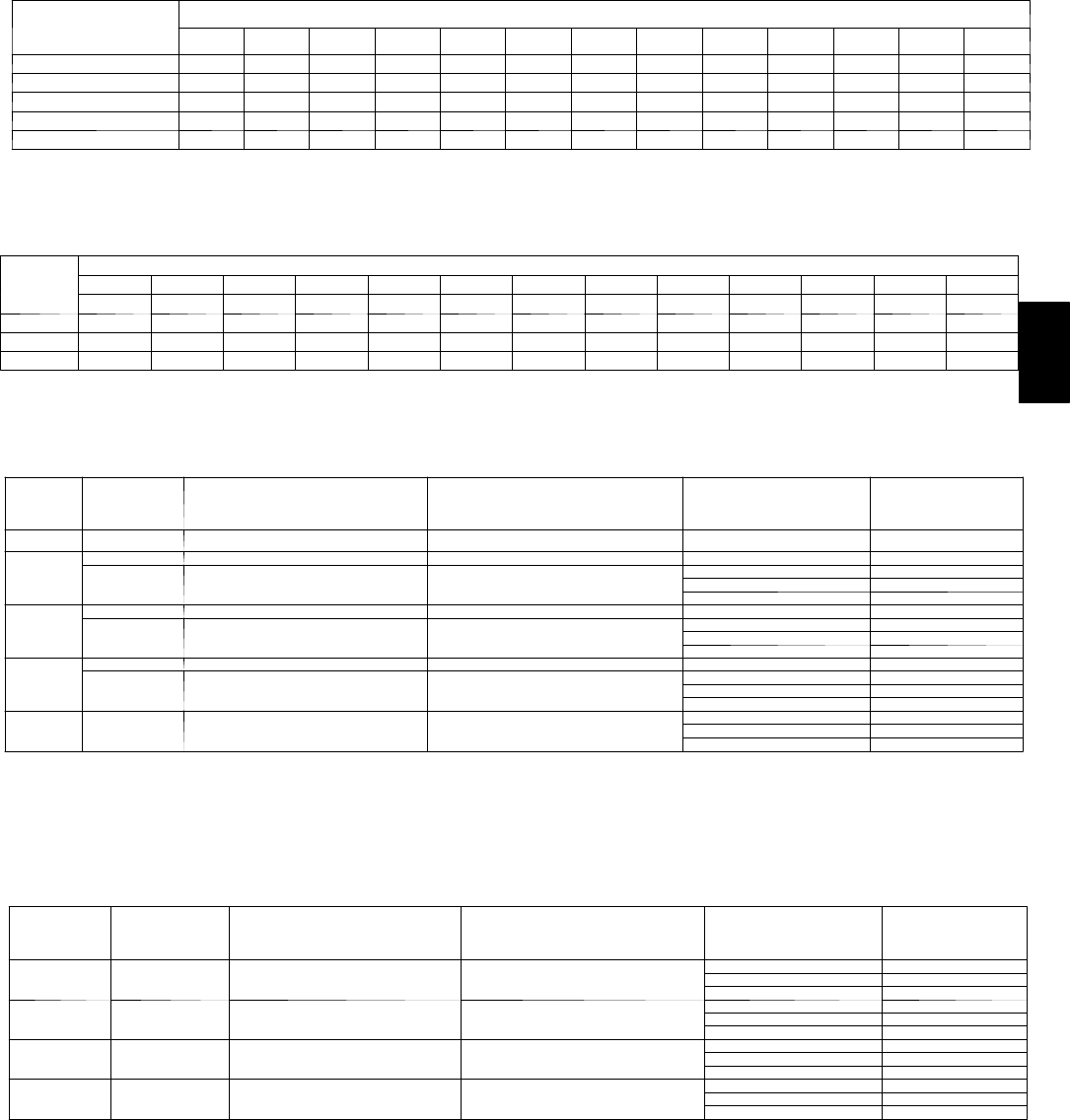
43
Table 9—50HJ and 50he Fan Rpm at Motor Pulley Setting With Standard Motor*
UNIT
50HJ
50HE
MOTOR PULLEY TURNS OPEN
01/21 11/22 21/23 31/24 41/25 51/26
003 936 906 876 846 816 786 756 726 696 666 639 — —
004 1044 1008 971 935 898 862 826 789 753 716 680 — —
005 1185 1144 1102 1061 1019 978 936 895 853 812 770 — —
006 1460 1425 1389 1354 1318 1283 1248 1212 1177 1141 1106 1070 1035
007 1585 1538 1492 1445 1399 1352 1305 1259 1212 1166 1119 — —
*Approximate fan rpm shown (standard motor/drive).
Table 10—50HJ, 50HE Fan Rpm at Motor Pulley Setting With High-Static Motor*
UNIT MOTOR PULLEY TURNS OPEN
01/21 11/22 21/23 31/24 41/25 51/26
004 1455 1423 1392 1360 1328 1297 1265 1233 1202 1170 1138 1107 1075
005 1455 1423 1392 1360 1328 1297 1265 1233 1202 1170 1138 1107 1075
006 1685 1589 1557 1525 1493 1460 1428 1396 1364 1332 1300 — —
007 1685 1589 1557 1525 1493 1460 1428 1396 1364 1332 1300 — —
*Approximate fan rpm shown (high-static motor/drive).
Table 11—Evaporator-Fan Motor Data — Standard Motor
UNIT
50HJ
50HE
UNIT
PHASE
MAXIMUM
CONTINUOUS BHP*
MAXIMUM
OPERATING WATTS* UNIT VOLTAGE MAXIMUM
AMP DRAW
003 ALL 0.58 580 2.0 75.0
004
Single 1.20 1000 208/230 4.9
Three 1.20 1000 208/230 4.9
460 2.2
575 2.2
005
Single 1.20 1000 208/230 4.9
Three 1.20 1000 208/230 4.9
460 2.2
575 2.2
006
Single 1.30 1650 208/230 9.2
Three 2.40 2120 208/230 6.7
460 3.0
575 3.0
007 Three 2.40 2120 208/230 6.7
460 3.0
575 3.0
LEGEND
Bhp — Brake Horsepower
*Extensive motor and electrical testing on these units ensures that the full horsepower and watts range of the motors can be utilized with confidence. Using the
fan motors up to the ratings shown in this table will not result in nuisance tripping or premature motor failure. Unit warranty will not be affected.
Table 12—Evaporator-Fan Motor Data — High-Static Motors
UNIT
50HJ
50HE
UNIT
PHASE
MAXIMUM
CONTINUOUS BHP*
MAXIMUM
OPERATING WATTS* UNIT VOLTAGE MAXIMUM
AMP DRAW
004 Three 2.40 2120 208/230 6.7
460 3.0
575 3.0
005 Three 2.40 2120 208/230 6.7
460 3.0
575 3.0
006 Three 2.90 2615 208/230 8.6
460 3.9
575 3.9
007 Three 2.90 2615 208/230 8.6
460 3.9
575 3.9
LEGEND
Bhp — Brake Horsepower
*Extensive motor and electrical testing on these units ensures that the full horsepower and watts range of the motors can be utilized with confidence. Using the
fan motors up to the ratings shown in this table will not result in nuisance tripping or premature motor failure. Unit warranty will not be affected.
50HE,HJ
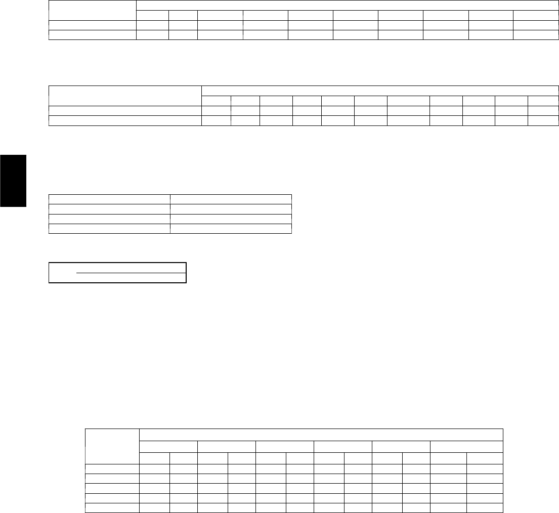
44
Table 13—Accessory/FIOP Electric Heaters Static Pressure Drop (in. wg) — 50HJ004-007 and 50HE003--006
COMPONENT CFM
600 900 1200 1400 1600 1800 2000 2200 2400 2600
1HeaterModule 0.03 0.05 0.07 0.09 0.09 0.10 0.11 0.11 0.12 0.13
2 Heater Modules 0.14 0.15 0.16 0.16 0.16 0.17 0.17 0.17 0.18 0.18
Table 14—Accessory/FIOP EconoMi$er IV and EconoMi$er2 Static Pressure* (in. wg) — 50HJ004-007 and 50HE003--006
COMPONENT CFM
600 800 1000 1250 1500 1750 2000 2250 2500 2750 3000
Vertical EconoMi$er IV and EconoMi$er2 0.01 0.02 0.035 0.045 0.065 0.08 0.12 0.145 0.175 0.22 0.255
Horizontal EconoMi$er IV and EconoMi$er2 --- --- --- — — 0.1 0.125 0.15 0.18 0.225 0.275
LEGEND
FIOP --- F a c t o r y --- I n s t a l l e d O p t i o n
*The static pressure must be added to external static pressure. The sum and the indoor entering-air cfm should be used in conjunction with the Fan Performance
tables to determine indoor blower rpm and watts.
Table 14 — Evaporator-Fan Motor Efficiency
MOTOR 50HJ EFFICIENCY
003,004,005 75
006 74/84*
007 84
*Single-phase/3-phase.
NOTE: Convert watts to bhp using the following formula:
bhp = watts input x motor efficiency
746
GENERAL FAN PERFORMANCE NOTES
1. Values include losses for filters, unit casing, and wet coils. See Table 13 and 14 and Fig. 46 for accessory/FIOP static pressure
information.
2. Extensive motor and electrical testing on these units ensures that the full range of the motor can be utilized with confidence. Using the
fan motors up to the ratings shown will not result in nuisance tripping or premature motor failure. Unit warranty will not be affected.
See Table 11 and 12 on this page for additional information.
3. Use of a field-supplied motor may affect wire sizing. Contact your Carrier representative to verify.
4. Interpolation is permissible. Do not extrapolate.
5. Performance includes clean filter and wet coil.
Table 15—Fan Performance 50HE003 — Vertical Discharge Units; Standard Motor (Belt Drive)**
AIRFLOW
(Cfm)
EXTERNAL STATIC PRESSURE (in. wg)
0.1 0.2 0.4 0.6 0.8 1.0
Rpm Bhp Rpm Bhp Rpm Bhp Rpm Bhp Rpm Bhp Rpm Bhp
600 500 0.08 531 0.08 607 0.14 713 0.21 788 0.29 878 0.37
700 529 0.09 567 0.09 633 0.16 739 0.24 816 0.32 902 0.41
800 547 0.1 592 0.12 660 0.19 761 0.27 845 0.37 937 0.47
900 570 0.13 620 0.14 691 0.22 793 0.32 870 0.42 957 0.53
1000 599 0.15 650 0.16 717 0.26 818 0.36 894 0.47 981 0.58
50HE,HJ
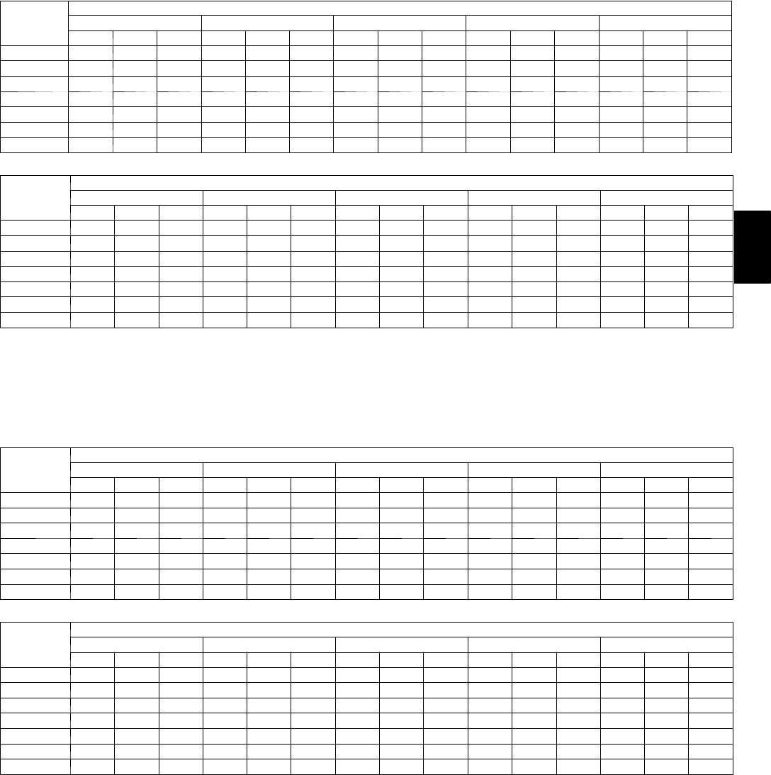
45
Table 16—Fan Performance 50HJ004, 50HE004 — Vertical Discharge Units; Standard Motor
(Belt Drive)*
AIRFLOW
CFM
EXTERNAL STATIC PRESSURE (in. wg
0.2 0.4 0.6 0.8 1.0
Rpm Bhp Watts Rpm Bhp Watts Rpm Bhp Watts Rpm Bhp Watts Rpm Bhp Watts
900 566 0.14 142 690 0.23 228 791 0.32 320 879 0.42 418 957 0.52 522
1000 598 0.17 173 718 0.27 267 817 0.37 366 903 0.47 471 981 0.58 581
1100 632 0.21 210 748 0.31 311 844 0.42 418 929 0.53 530 1006 0.65 646
1200 666 0.25 252 778 0.36 361 873 0.48 476 956 0.60 594 1031 0.72 718
1300 701 0.30 300 809 0.42 418 902 0.54 540 983 0.67 665 1057 0.80 796
1400 737 0.36 355 842 0.48 481 932 0.61 610 1012 0.75 744 1085 0.89 881
1500 774 0.42 417 875 0.55 551 962 0.69 689 1041 0.83 830 1112 0.98 974
AIRFLOW
CFM
EXTERNAL STATIC PRESSURE (in. wg)
1.2 1.4 1.6 1.8 2.0
Rpm Bhp Watts Rpm Bhp Watts Rpm Bhp Watts Rpm Bhp Watts Rpm Bhp Watts
900 1029 0.63 630 1095 0.75 742 1157 0.86 859 1216 0.99 980 1272 1.11 1105
1000 1052 0.70 695 1118 0.82 814 1179 0.94 937 1237 1.07 1064 1293 1.20 1195
1100 1076 0.77 767 1141 0.90 892 1202 1.03 1021 1260 1.16 1154 — — —
1200 1100 0.85 845 1165 0.98 977 1225 1.12 1112 ——————
1300 1126 0.94 930 1189 1.07 1069 —————————
1400 1152 1.03 1023 1215 1.17 1168 —————————
1500 1179 1.13 1123 ————————————
NOTES:
1. Bold cells indicate field-supplied drive is required.
2. Maximum continuous bhp is 1.20.
3. See general fan performance notes.
LEGEND
Bhp — Brake Horsepower
Watts — Input Watts to Motor
*Motor drive range: 680 to 1044 rpm. All other rpms require field-supplied
drive.
Table 17—Fan Performance 50HJ004, 50he004 — Vertical Discharge Units; High-Static Motor
(Belt Drive)*
AIRFLOW
CFM
EXTERNAL STATIC PRESSURE (in. wg)
0.2 0.4 0.6 0.8 1.0
Rpm Bhp Watts Rpm Bhp Watts Rpm Bhp Watts Rpm Bhp Watts Rpm Bhp Watts
900 566 0.14 142 690 0.23 228 791 0.32 320 879 0.42 418 957 0.52 522
1000 598 0.17 173 718 0.27 267 817 0.37 366 903 0.47 471 981 0.58 581
1100 632 0.21 210 748 0.31 311 844 0.42 418 929 0.53 530 1006 0.65 646
1200 666 0.25 252 778 0.36 361 873 0.48 476 956 0.60 594 1031 0.72 718
1300 701 0.30 300 809 0.42 418 902 0.54 540 983 0.67 665 1057 0.80 796
1400 737 0.36 355 842 0.48 481 932 0.61 610 1012 0.75 744 1085 0.89 881
1500 774 0.42 417 875 0.55 551 962 0.69 689 1041 0.83 830 1112 0.98 974
AIRFLOW
CFM
EXTERNAL STATIC PRESSURE (in. wg)
1.2 1.4 1.6 1.8 2.0
Rpm Bhp Watts Rpm Bhp Watts Rpm Bhp Watts Rpm Bhp Watts Rpm Bhp Watts
900 1029 0.63 630 1095 0.75 742 1157 0.86 859 1216 0.99 980 1272 1.11 1105
1000 1052 0.70 695 1118 0.82 814 1179 0.94 937 1237 1.07 1064 1293 1.20 1195
1100 1076 0.77 767 1141 0.90 892 1202 1.03 1021 1260 1.16 1154 1314 1.30 1291
1200 1100 0.85 845 1165 0.98 977 1225 1.12 1112 1282 1.26 1252 1337 1.40 1395
1300 1126 0.94 930 1189 1.07 1069 1249 1.22 1211 1306 1.36 1356 1360 1.51 1506
1400 1152 1.03 1023 1215 1.17 1168 1274 1.32 1317 1330 1.48 1469 1384 1.63 1625
1500 1179 1.13 1123 1241 1.28 1275 1300 1.44 1431 1355 1.60 1590 1408 1.76 1752
NOTES:
1. Bold cells indicate field-supplied drive is required.
2. Maximum continuous bhp is 1.20.
3. See general fan performance notes.
LEGEND
Bhp — Brake Horsepower
Watts — Input Watts to Motor
*Motor drive range: 680 to 1044 rpm. All other rpms require field-supplied
drive.
50HE,HJ
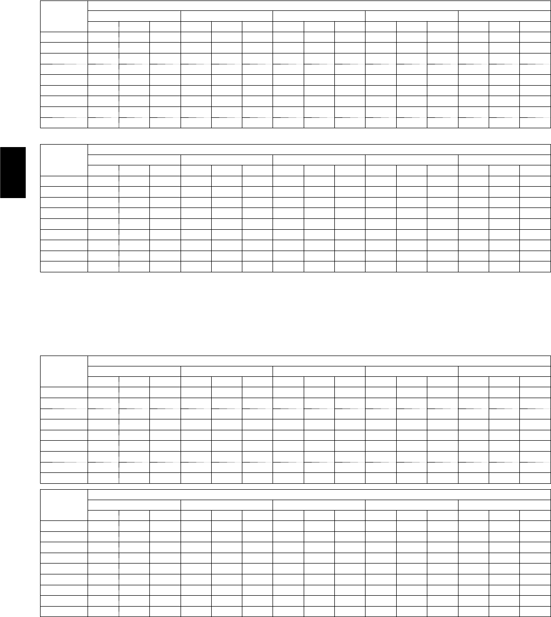
46
Table 18—Fan Performance 50HJ005, 50HE005 — Vertical Discharge Units; Standard Motor
(Belt Drive)*
AIRFLOW
CFM
EXTERNAL STATIC PRESSURE (in. wg)
0.2 0.4 0.6 0.8 1.0
Rpm Bhp Watts Rpm Bhp Watts Rpm Bhp Watts Rpm Bhp Watts Rpm Bhp Watts
1200 666 0.25 252 778 0.36 361 873 0.48 476 956 0.60 594 1031 0.72 718
1300 701 0.30 300 809 0.42 418 902 0.54 540 983 0.67 665 1057 0.80 796
1400 737 0.36 355 842 0.48 481 932 0.61 610 1012 0.75 744 1085 0.89 881
1500 774 0.42 417 875 0.55 551 962 0.69 689 1041 0.83 830 1112 0.98 974
1600 811 0.49 487 909 0.63 629 994 0.78 774 1071 0.93 923 1141 1.08 1076
1700 849 0.57 565 943 0.72 715 1026 0.87 869 1101 1.03 1025 1170 1.19 1185
1800 887 0.65 651 978 0.81 810 1059 0.98 972 1133 1.14 1136 ———
1900 926 0.75 746 1014 0.92 914 1092 1.09 1084 ——————
2000 965 0.86 852 1050 1.03 1028 —————————
AIRFLOW
CFM
EXTERNAL STATIC PRESSURE (in. wg)
1.2 1.4 1.6 1.8 2.0
Rpm Bhp Watts Rpm Bhp Watts Rpm Bhp Watts Rpm Bhp Watts Rpm Bhp Watts
1200 1100 0.85 845 1165 0.98 977 1225 1.12 1112 ——————
1300 1126 0.94 930 1189 1.07 1069 —————————
1400 1152 1.03 1023 1215 1.17 1168 —————————
1500 1179 1.13 1123 ————————————
1600 ———————————————
1700 ———————————————
1800 ———————————————
1900 ———————————————
2000 ———————————————
NOTES:
1. Bold cells indicate field-supplied drive is required.
2. Maximum continuous bhp is 1.20.
3. See general fan performance notes.
LEGEND
Bhp — Brake Horsepower
Watts — Input Watts to Motor
*Motor drive range: 770 to 1185 rpm. All other rpms require field-supplied
drive.
Table 19—Fan Performance 50HJ005, 50HE005 — Vertical Discharge Units; High-Static Motor
(Belt Drive)*
AIRFLOW
CFM
EXTERNAL STATIC PRESSURE (in. wg)
0.2 0.4 0.6 0.8 1.0
Rpm Bhp Watts Rpm Bhp Watts Rpm Bhp Watts Rpm Bhp Watts Rpm Bhp Watts
1200 666 0.25 252 778 0.36 361 873 0.48 476 956 0.60 594 1031 0.72 718
1300 701 0.30 300 809 0.42 418 902 0.54 540 983 0.67 665 1057 0.80 796
1400 737 0.36 355 842 0.48 481 932 0.61 610 1012 0.75 744 1085 0.89 881
1500 774 0.42 417 875 0.55 551 962 0.69 689 1041 0.83 830 1112 0.98 974
1600 811 0.49 487 909 0.63 629 994 0.78 774 1071 0.93 923 1141 1.08 1076
1700 849 0.57 565 943 0.72 715 1026 0.87 869 1101 1.03 1025 1170 1.19 1185
1800 887 0.65 651 978 0.81 810 1059 0.98 972 1133 1.14 1136 1200 1.31 1304
1900 926 0.75 746 1014 0.92 914 1092 1.09 1084 1164 1.26 1257 1231 1.44 1432
2000 965 0.86 852 1050 1.03 1028 1127 1.21 1206 1197 1.39 1387 1262 1.58 1570
AIRFLOW
CFM
EXTERNAL STATIC PRESSURE (in. wg)
1.2 1.4 1.6 1.8 2.0
Rpm Bhp Watts Rpm Bhp Watts Rpm Bhp Watts Rpm Bhp Watts Rpm Bhp Watts
1200 1100 0.85 845 1165 0.98 977 1225 1.12 1112 1282 1.26 1252 1337 1.40 1395
1300 1126 0.94 930 1189 1.07 1069 1249 1.22 1211 1306 1.36 1356 1360 1.51 1506
1400 1152 1.03 1023 1215 1.17 1168 1274 1.32 1317 1330 1.48 1469 1384 1.63 1625
1500 1179 1.13 1123 1241 1.28 1275 1300 1.44 1431 1355 1.60 1590 1408 1.76 1752
1600 1206 1.24 1231 1268 1.40 1391 1326 1.56 1553 1381 1.73 1719 1433 1.90 1888
1700 1235 1.36 1349 1295 1.52 1515 1352 1.69 1685 1407 1.87 1858 1459 2.04 2034
1800 1264 1.48 1475 1323 1.66 1649 1380 1.84 1826 1434 2.02 2006 1485 2.20 2189
1900 1293 1.62 1611 1352 1.80 1792 1408 1.99 1976 1461 2.17 2163 1512 2.37 2353
2000 1324 1.77 1756 1381 1.96 1945 1436 2.15 2137 1489 2.34 2332 ———
NOTES:
1. Bold cells indicate field-supplied drive is required.
2. Maximum continuous bhp is 2.40.
3. See general fan performance notes.
LEGEND
Bhp — Brake Horsepower
Watts — Input Watts to Motor
*Motor drive range: 1075 to 1455 rpm. All other rpms require field-supplied
drive.
50HE,HJ

47
Table 20—Fan Performance 50HJ006, 50HE006 Single-Phase — Vertical Discharge Units; Standard Motor (Belt Drive)*
AIRFLOW
CFM
EXTERNAL STATIC PRESSURE (in. wg)
0.2 0.4 0.6 0.8 1.0
Rpm Bhp Watts Rpm Bhp Watts Rpm Bhp Watts Rpm Bhp Watts Rpm Bhp Watts
1500 790 0.40 353 897 0.53 471 991 0.68 600 1075 0.83 739 1152 1.00 888
1600 828 0.46 412 931 0.60 536 1022 0.75 670 1104 0.92 813 1180 1.09 966
1700 866 0.54 478 966 0.68 608 1054 0.84 747 1134 1.01 895 1208 1.19 1053
1800 905 0.62 551 1001 0.77 687 1087 0.94 832 1165 1.11 985 1238 1.29 1148
1900 944 0.71 633 1037 0.87 774 1120 1.04 925 1197 1.22 1084 ———
2000 983 0.81 723 1073 0.98 870 1154 1.16 1026 ——————
2100 1023 0.92 821 1110 1.10 975 1189 1.28 1137 ——————
2200 1063 1.05 929 1147 1.23 1089 —————————
2300 1104 1.18 1046 ————————————
2400 ———————————————
2500 ———————————————
AIRFLOW
CFM
EXTERNAL STATIC PRESSURE (in. wg)
1.2 1.4 1.6 1.8 2.0
Rpm Bhp Watts Rpm Bhp Watts Rpm Bhp Watts Rpm Bhp Watts Rpm Bhp Watts
1500 1224 1.18 1045 ————————————
1600 1250 1.27 1128 ————————————
1700 ———————————————
1800 ———————————————
1900 ———————————————
2000 ———————————————
2100 ———————————————
2200 ———————————————
2300 ———————————————
2400 ———————————————
2500 ———————————————
NOTES:
1. Bold cells indicate field-supplied drive is required.
2. Maximum continuous bhp is 1.30.
3. See general fan performance notes.
LEGEND
Bhp — Brake Horsepower
Watts — Input Watts to Motor
*Motor drive range: 1035 to 1460 rpm. All other rpms require field-supplied
drive.
50HE,HJ
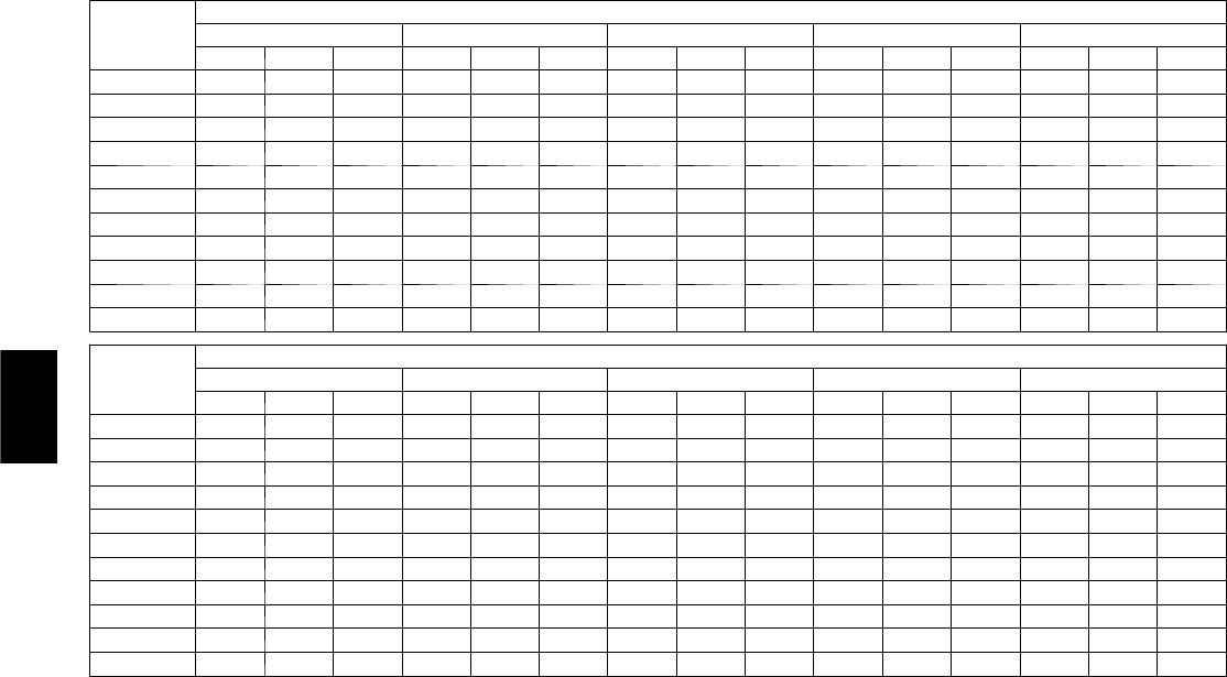
48
Table 21—Fan Performance 50HJ006, 50he006 Three-Phase — Vertical Discharge Units; Standard Motor (Belt Drive)*
AIRFLOW
CFM
EXTERNAL STATIC PRESSURE (in. wg)
0.2 0.4 0.6 0.8 1.0
Rpm Bhp Watts Rpm Bhp Watts Rpm Bhp Watts Rpm Bhp Watts Rpm Bhp Watts
1500 790 0.40 353 897 0.53 471 991 0.68 600 1075 0.83 739 1152 1.00 888
1600 828 0.46 412 931 0.60 536 1022 0.75 670 1104 0.92 813 1180 1.09 966
1700 866 0.54 478 966 0.68 608 1054 0.84 747 1134 1.01 895 1208 1.19 1053
1800 905 0.62 551 1001 0.77 687 1087 0.94 832 1165 1.11 985 1238 1.29 1148
1900 944 0.71 633 1037 0.87 774 1120 1.04 925 1197 1.22 1084 1268 1.41 1251
2000 983 0.81 723 1073 0.98 870 1154 1.16 1026 1229 1.34 1190 1299 1.53 1362
2100 1023 0.92 821 1110 1.10 975 1189 1.28 1137 1262 1.47 1306 1330 1.67 1483
2200 1063 1.05 929 1147 1.23 1089 1224 1.41 1256 1295 1.61 1431 1362 1.82 1614
2300 1104 1.18 1046 1185 1.37 1212 1260 1.56 1386 1329 1.76 1567 1395 1.98 1754
2400 1145 1.32 1174 1223 1.52 1346 1296 1.72 1526 1364 1.93 1712 1428 2.15 1905
2500 1185 1.48 1311 1262 1.68 1490 1333 1.89 1676 1399 2.10 1868 1462 2.33 2067
AIRFLOW
CFM
EXTERNAL STATIC PRESSURE (in. wg)
1.2 1.4 1.6 1.8 2.0
Rpm Bhp Watts Rpm Bhp Watts Rpm Bhp Watts Rpm Bhp Watts Rpm Bhp Watts
1500 1224 1.18 1045 1291 1.36 1212 1354 1.56 1387 1414 1.77 1570 1472 1.98 1761
1600 1250 1.27 1128 1316 1.46 1299 1379 1.66 1478 1438 1.87 1664 1495 2.09 1858
1700 1278 1.37 1219 1343 1.57 1394 1405 1.77 1576 1463 1.99 1766 1520 2.21 1964
1800 1306 1.48 1318 1370 1.69 1497 1431 1.90 1683 1489 2.11 1877 1545 2.34 2078
1900 1335 1.61 1426 1398 1.81 1609 1458 2.03 1799 1515 2.25 1997 ———
2000 1364 1.74 1542 1427 1.95 1730 1486 2.17 1925 1542 2.39 2126 ———
2100 1395 1.88 1668 1456 2.09 1860 1514 2.32 2060 ——————
2200 1426 2.03 1804 1486 2.25 2001 —————————
2300 1457 2.19 1949 ————————————
2400 1489 2.37 2106 ————————————
2500 ———————————————
NOTES:
1. Bold cells indicate field-supplied drive is required.
2. Maximum continuous bhp is 2.40.
3. See general fan performance notes.
LEGEND
Bhp — Brake Horsepower
Watts — Input Watts to Motor
*Motor drive range: 1035 to 1460 rpm. All other rpms require field-supplied
drive.
50HE,HJ
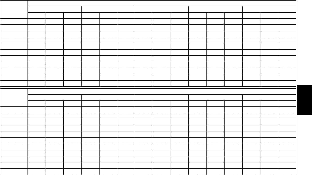
49
Table 22—Fan Performance 50HJ006, 50HE006 — Vertical Discharge Units; High-Static Motor
(Belt Drive)*
AIRFLOW
CFM
EXTERNAL STATIC PRESSURE (in. wg)
0.2 0.4 0.6 0.8 1.0
Rpm Bhp Watts Rpm Bhp Watts Rpm Bhp Watts Rpm Bhp Watts Rpm Bhp Watts
1500 790 0.40 353 897 0.53 471 991 0.68 600 1075 0.83 739 1152 1.00 888
1600 828 0.46 412 931 0.60 536 1022 0.75 670 1104 0.92 813 1180 1.09 966
1700 866 0.54 478 966 0.68 608 1054 0.84 747 1134 1.01 895 1208 1.19 1053
1800 905 0.62 551 1001 0.77 687 1087 0.94 832 1165 1.11 985 1238 1.29 1148
1900 944 0.71 633 1037 0.87 774 1120 1.04 925 1197 1.22 1084 1268 1.41 1251
2000 983 0.81 723 1073 0.98 870 1154 1.16 1026 1229 1.34 1190 1299 1.53 1362
2100 1023 0.92 821 1110 1.10 975 1189 1.28 1137 1262 1.47 1306 1330 1.67 1483
2200 1063 1.05 929 1147 1.23 1089 1224 1.41 1256 1295 1.61 1431 1362 1.82 1614
2300 1104 1.18 1046 1185 1.37 1212 1260 1.56 1386 1329 1.76 1567 1395 1.98 1754
2400 1145 1.32 1174 1223 1.52 1346 1296 1.72 1526 1364 1.93 1712 1428 2.15 1905
2500 1185 1.48 1311 1262 1.68 1490 1333 1.89 1676 1399 2.10 1868 1462 2.33 2067
AIRFLOW
CFM
EXTERNAL STATIC PRESSURE (in. wg)
1.2 1.4 1.6 1.8 2.0
Rpm Bhp Watts Rpm Bhp Watts Rpm Bhp Watts Rpm Bhp Watts Rpm Bhp Watts
1500 1224 1.18 1045 1291 1.36 1212 1354 1.56 1387 1414 1.77 1570 1472 1.98 1761
1600 1250 1.27 1128 1316 1.46 1299 1379 1.66 1478 1438 1.87 1664 1495 2.09 1858
1700 1278 1.37 1219 1343 1.57 1394 1405 1.77 1576 1463 1.99 1766 1520 2.21 1964
1800 1306 1.48 1318 1370 1.69 1497 1431 1.90 1683 1489 2.11 1877 1545 2.34 2078
1900 1335 1.61 1426 1398 1.81 1609 1458 2.03 1799 1515 2.25 1997 1570 2.48 2202
2000 1364 1.74 1542 1427 1.95 1730 1486 2.17 1925 1542 2.39 2126 1596 2.63 2335
2100 1395 1.88 1668 1456 2.09 1860 1514 2.32 2060 1570 2.55 2265 1623 2.79 2478
2200 1426 2.03 1804 1486 2.25 2001 1543 2.48 2204 1598 2.72 2415 ———
2300 1457 2.19 1949 1516 2.42 2151 1573 2.66 2360 1627 2.90 2574 ———
2400 1489 2.37 2106 1547 2.60 2312 1603 2.84 2526 ——————
2500 1522 2.56 2272 1579 2.80 2484 —————————
NOTES:
1. Bold cells indicate field-supplied drive is required.
2. Maximum continuous bhp is 2.90.
3. See general fan performance notes.
LEGEND
Bhp — Brake Horsepower
Watts — Input Watts to Motor
*Motor drive range: 1300 to 1685 rpm. All other rpms require field-supplied
drive.
50HE,HJ
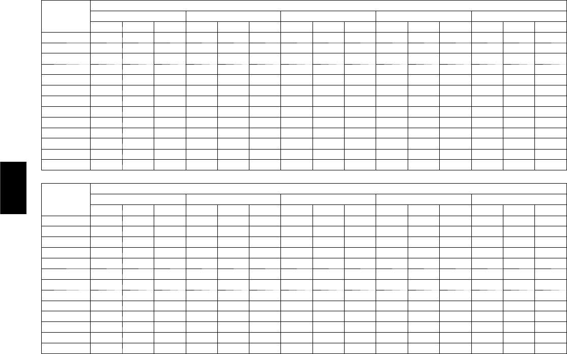
50
Table 23—Fan Performance 50HJ007 — Vertical Discharge Units; Standard Motor (Belt Drive)*
AIRFLOW
CFM
EXTERNAL STATIC PRESSURE (in. wg)
0.2 0.4 0.6 0.8 1.0
Rpm Bhp Watts Rpm Bhp Watts Rpm Bhp Watts Rpm Bhp Watts Rpm Bhp Watts
1800 907 0.63 558 1006 0.80 708 1092 0.97 860 1169 1.14 1015 1239 1.32 1174
1900 945 0.72 638 1042 0.90 796 1126 1.08 956 1201 1.26 1119 1271 1.45 1285
2000 984 0.82 727 1078 1.00 892 1160 1.19 1060 1235 1.39 1230 1303 1.58 1403
2100 1024 0.93 823 1115 1.12 997 1195 1.32 1173 1268 1.52 1350 1335 1.72 1531
2200 1063 1.05 929 1152 1.25 1111 1230 1.46 1294 1302 1.67 1480 1368 1.88 1668
2300 1103 1.18 1044 1189 1.39 1234 1266 1.60 1425 1337 1.82 1618 1402 2.04 1814
2400 1143 1.32 1168 1227 1.54 1367 1302 1.76 1566 1371 1.99 1767 1435 2.22 1970
2500 1183 1.47 1303 1265 1.70 1510 1339 1.93 1717 1406 2.17 1926 ———
2600 1224 1.63 1448 1303 1.87 1663 1375 2.12 1878 1442 2.36 2095 ———
2700 1264 1.81 1604 1342 2.06 1828 1412 2.31 2051 ——————
2800 1305 1.99 1772 1381 2.26 2003 —————————
2900 1346 2.20 1951 ————————————
3000 ———————————————
AIRFLOW
CFM
EXTERNAL STATIC PRESSURE (in. wg)
1.2 1.4 1.6 1.8 2.0
Rpm Bhp Watts Rpm Bhp Watts Rpm Bhp Watts Rpm Bhp Watts Rpm Bhp Watts
1800 1304 1.51 1337 1365 1.69 1503 1422 1.88 1674 1477 2.08 1848 1528 2.28 2025
1900 1335 1.64 1454 1395 1.83 1627 1452 2.03 1804 1506 2.23 1984 ———
2000 1366 1.78 1580 1426 1.98 1760 1482 2.19 1943 1535 2.40 2130 ———
2100 1398 1.93 1715 1457 2.14 1901 1512 2.35 2091 ——————
2200 1430 2.09 1858 1488 2.31 2052 —————————
2300 1462 2.27 2012 ————————————
2400 ———————————————
2500 ———————————————
2600 ———————————————
2700 ———————————————
2800 ———————————————
2900 ———————————————
3000 ———————————————
NOTES:
1. Bold cells indicate field-supplied drive is required.
2. Maximum continuous bhp is 2.40.
3. See general fan performance notes.
LEGEND
Bhp — Brake Horsepower
Watts — Input Watts to Motor
*Motor drive range: 1120 to 1585 rpm. All other rpms require field-supplied
drive.
50HE,HJ
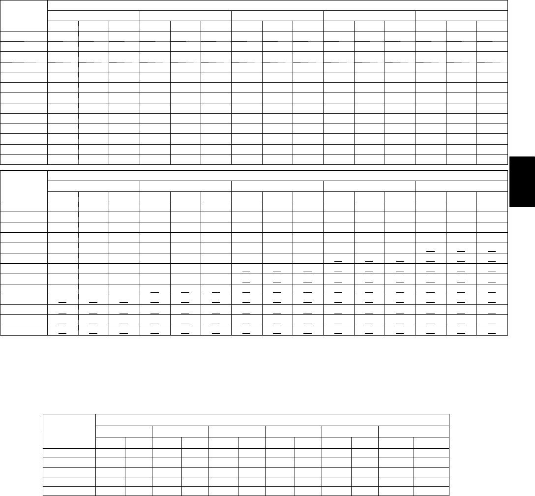
51
Table 24—Fan Performance 50HJ007 — Vertical Discharge Units; High-Static Motor (Belt Drive)*
AIRFLOW
CFM
EXTERNAL STATIC PRESSURE (in. wg)
0.2 0.4 0.6 0.8 1.0
Rpm Bhp Watts Rpm Bhp Watts Rpm Bhp Watts Rpm Bhp Watts Rpm Bhp Watts
1800 907 0.63 558 1006 0.80 708 1092 0.97 860 1169 1.14 1015 1239 1.32 1174
1900 945 0.72 638 1042 0.90 796 1126 1.08 956 1201 1.26 1119 1271 1.45 1285
2000 984 0.82 727 1078 1.00 892 1160 1.19 1060 1235 1.39 1230 1303 1.58 1403
2100 1024 0.93 823 1115 1.12 997 1195 1.32 1173 1268 1.52 1350 1335 1.72 1531
2200 1063 1.05 929 1152 1.25 1111 1230 1.46 1294 1302 1.67 1480 1368 1.88 1668
2300 1103 1.18 1044 1189 1.39 1234 1266 1.60 1425 1337 1.82 1618 1402 2.04 1814
2400 1143 1.32 1168 1227 1.54 1367 1302 1.76 1566 1371 1.99 1767 1435 2.22 1970
2500 1183 1.47 1303 1265 1.70 1510 1339 1.93 1717 1406 2.17 1926 1470 2.41 2136
2600 1224 1.63 1448 1303 1.87 1663 1375 2.12 1878 1442 2.36 2095 1504 2.60 2313
2700 1264 1.81 1604 1342 2.06 1828 1412 2.31 2051 1478 2.56 2275 1539 2.82 2501
2800 1305 1.99 1772 1381 2.26 2003 1450 2.52 2235 1514 2.78 2467 ———
2900 1346 2.20 1951 1420 2.47 2191 1488 2.74 2431 ——————
3000 1387 2.41 2142 1459 2.69 2391 —————————
AIRFLOW
CFM
EXTERNAL STATIC PRESSURE (in. wg)
1.2 1.4 1.6 1.8 2.0
Rpm Bhp Watts Rpm Bhp Watts Rpm Bhp Watts Rpm Bhp Watts Rpm Bhp Watts
1800 1304 1.51 1337 1365 1.69 1503 1422 1.88 1674 1477 2.08 1848 1528 2.28 2025
1900 1335 1.64 1454 1395 1.83 1627 1452 2.03 1804 1506 2.23 1984 1557 2.44 2168
2000 1366 1.78 1580 1426 1.98 1760 1482 2.19 1943 1535 2.40 2130 1586 2.61 2319
2100 1398 1.93 1715 1457 2.14 1901 1512 2.35 2091 1565 2.57 2284 1616 2.79 2481
2200 1430 2.09 1858 1488 2.31 2052 1543 2.53 2249 1596 2.76 2449 ———
2300 1462 2.27 2012 1520 2.49 2212 1574 2.72 2416 ——————
2400 1495 2.45 2175 1552 2.68 2383 —————————
2500 1529 2.64 2349 1585 2.89 2564 —————————
2600 1562 2.85 2533 ————————————
2700 ———————————————
2800 ———————————————
2900 ———————————————
3000 ———————————————
NOTES:
1. Bold cells indicate field-supplied drive is required.
2. Maximum continuous bhp is 2.90.
3. See general fan performance notes.
LEGEND
Bhp — Brake Horsepower
Watts — Input Watts to Motor
*Motor drive range: 1300 to 1685 rpm. All other rpms require field-supplied
drive.
Table 25—Fan Performance 50HE003 — Horizontal Discharge Units; Standard Motor (Belt Drive)**
AIRFLOW
(Cfm)
EXTERNAL STATIC PRESSURE (in. wg)
0.1 0.2 0.4 0.6 0.8 1.0
Rpm Bhp Rpm Bhp Rpm Bhp Rpm Bhp Rpm Bhp Rpm Bhp
600 490 0.08 521 0.08 597 0.14 703 0.21 788 0.29 868 0.37
700 519 0.09 557 0.09 623 0.16 729 0.24 816 0.32 892 0.41
800 537 0.1 582 0.12 650 0.19 751 0.27 845 0.37 927 0.47
900 560 0.13 610 0.14 681 0.22 783 0.32 870 0.42 947 0.53
1000 589 0.15 640 0.16 707 0.26 808 0.36 894 0.47 971 0.58
50HE,HJ
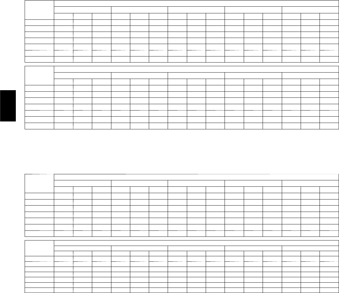
52
Table 26—Fan Performance 50HJ004, 50HE004 — Horizontal Discharge Units; Standard Motor
(Belt Drive)*
AIRFLOW
CFM
EXTERNAL STATIC PRESSURE (in. wg)
0.2 0.4 0.6 0.8 1.0
Rpm Bhp Watts Rpm Bhp Watts Rpm Bhp Watts Rpm Bhp Watts Rpm Bhp Watts
900 554 0.14 134 681 0.22 222 783 0.32 316 870 0.42 416 947 0.53 523
1000 583 0.16 163 707 0.26 257 808 0.36 358 894 0.47 465 971 0.58 578
1100 612 0.20 195 735 0.30 298 834 0.41 406 919 0.52 519 995 0.64 638
1200 643 0.23 233 762 0.35 344 860 0.46 459 944 0.58 579 1020 0.71 705
1300 674 0.28 276 791 0.40 395 887 0.52 517 970 0.65 645 1045 0.78 777
1400 706 0.33 324 820 0.45 451 914 0.59 582 997 0.72 717 1071 0.86 857
1500 738 0.38 379 849 0.52 515 942 0.66 653 1024 0.80 796 1097 0.95 942
AIRFLOW
CFM
EXTERNAL STATIC PRESSURE (in. wg)
1.2 1.4 1.6 1.8 2.0
Rpm Bhp Watts Rpm Bhp Watts Rpm Bhp Watts Rpm Bhp Watts Rpm Bhp Watts
900 1017 0.64 635 1082 0.76 753 1143 0.88 876 1200 1.01 1004 1254 1.14 1136
1000 1041 0.70 696 1105 0.82 820 1166 0.95 948 1223 1.09 1081 ———
1100 1065 0.77 763 1129 0.90 892 1189 1.03 1026 1245 1.17 1165 ———
1200 1089 0.84 835 1153 0.98 971 1212 1.12 1111 ——————
1300 1114 0.92 915 1177 1.06 1056 —————————
1400 1139 1.01 1000 1202 1.15 1149 —————————
1500 1164 1.10 1093 ————————————
NOTES:
1. Bold cells indicate field-supplied drive is required.
2. Maximum continuous bhp is 1.20.
3. See general fan performance notes.
LEGEND
Bhp — Brake Horsepower
Watts — Input Watts to Motor
*Motor drive range: 680 to 1044 rpm. All other rpms require field-supplied
drive.
Table 27—Fan Performance 50HJ004, 50HE004 — Horizontal Discharge Units; High-Static Motor (Belt Drive)*
AIRFLOW
CFM
EXTERNAL STATIC PRESSURE (in. wg)
0.2 0.4 0.6 0.8 1.0
Rpm Bhp Watts Rpm Bhp Watts Rpm Bhp Watts Rpm Bhp Watts Rpm Bhp Watts
900 554 0.14 134 681 0.22 222 783 0.32 316 870 0.42 416 947 0.53 523
1000 583 0.16 163 707 0.26 257 808 0.36 358 894 0.47 465 971 0.58 578
1100 612 0.20 195 735 0.30 298 834 0.41 406 919 0.52 519 995 0.64 638
1200 643 0.23 233 762 0.35 344 860 0.46 459 944 0.58 579 1020 0.71 705
1300 674 0.28 276 791 0.40 395 887 0.52 517 970 0.65 645 1045 0.78 777
1400 706 0.33 324 820 0.45 451 914 0.59 582 997 0.72 717 1071 0.86 857
1500 738 0.38 379 849 0.52 515 942 0.66 653 1024 0.80 796 1097 0.95 942
AIRFLOW
CFM
EXTERNAL STATIC PRESSURE (in. wg)
1.2 1.4 1.6 1.8 2.0
Rpm Bhp Watts Rpm Bhp Watts Rpm Bhp Watts Rpm Bhp Watts Rpm Bhp Watts
900 1017 0.64 635 1082 0.76 753 1143 0.88 876 1200 1.01 1004 1254 1.14 1136
1000 1041 0.70 696 1105 0.82 820 1166 0.95 948 1223 1.09 1081 1276 1.23 1219
1100 1065 0.77 763 1129 0.90 892 1189 1.03 1026 1245 1.17 1165 1299 1.32 1308
1200 1089 0.84 835 1153 0.98 971 1212 1.12 1111 1269 1.26 1256 1322 1.41 1404
1300 1114 0.92 915 1177 1.06 1056 1236 1.21 1202 1292 1.36 1353 1346 1.52 1508
1400 1139 1.01 1000 1202 1.15 1149 1261 1.31 1301 1316 1.47 1457 1369 1.63 1618
1500 1164 1.10 1093 1227 1.25 1248 1285 1.41 1407 1341 1.58 1570 1394 1.75 1736
NOTES:
1. Bold cells indicate field-supplied drive is required.
2. Maximum continuous bhp is 2.40.
3. See general fan performance notes.
LEGEND
Bhp — Brake Horsepower
Watts — Input Watts to Motor
*Motor drive range: 1075 to 1455 rpm. All other rpms require field-supplied
drive.
50HE,HJ

53
Table 28—Fan Performance 50HJ005, 50he005 — Horizontal Discharge Units; Standard Motor
(Belt Drive)*
AIRFLOW
CFM
EXTERNAL STATIC PRESSURE (in. wg)
0.2 0.4 0.6 0.8 1.0
Rpm Bhp Watts Rpm Bhp Watts Rpm Bhp Watts Rpm Bhp Watts Rpm Bhp Watts
1200 643 0.23 233 762 0.35 344 860 0.46 459 944 0.58 579 1020 0.71 705
1300 674 0.28 276 791 0.40 395 887 0.52 517 970 0.65 645 1045 0.78 777
1400 706 0.33 324 820 0.45 451 914 0.59 582 997 0.72 717 1071 0.86 857
1500 738 0.38 379 849 0.52 515 942 0.66 653 1024 0.80 796 1097 0.95 942
1600 771 0.44 440 879 0.59 584 971 0.74 731 1051 0.89 881 1124 1.04 1035
1700 804 0.51 507 910 0.66 661 1000 0.82 816 1079 0.98 974 1151 1.14 1136
1800 837 0.59 582 941 0.75 745 1029 0.91 909 1107 1.08 1075 ———
1900 871 0.67 665 972 0.84 837 1059 1.02 1010 1136 1.19 1184 ———
2000 906 0.76 756 1004 0.94 938 1089 1.12 1119 ——————
AIRFLOW
CFM
EXTERNAL STATIC PRESSURE (in. wg)
1.2 1.4 1.6 1.8 2.0
Rpm Bhp Watts Rpm Bhp Watts Rpm Bhp Watts Rpm Bhp Watts Rpm Bhp Watts
1200 1089 0.84 835 1153 0.98 971 1212 1.12 1111 ——————
1300 1114 0.92 915 1177 1.06 1056 —————————
1400 1139 1.01 1000 1202 1.15 1149 —————————
1500 1164 1.10 1093 ————————————
1600 1190 1.20 1193 ————————————
1700 ———————————————
1800 ———————————————
1900 ———————————————
2000 ———————————————
NOTES:
1. Bold cells indicate field-supplied drive is required.
2. Maximum continuous bhp is 1.20.
3. See general fan performance notes.
LEGEND
Bhp — Brake Horsepower
Watts — Input Watts to Motor
*Motor drive range: 770 to 1185 rpm. All other rpms require field-supplied
drive.
Table 29—Fan Performance 50HJ005, 50HE005 — Horizontal Discharge Units; High-Static Motor (Belt Drive)*
AIRFLOW
CFM
EXTERNAL STATIC PRESSURE (in. wg)
0.2 0.4 0.6 0.8 1.0
Rpm Bhp Watts Rpm Bhp Watts Rpm Bhp Watts Rpm Bhp Watts Rpm Bhp Watts
1200 643 0.23 233 762 0.35 344 860 0.46 459 944 0.58 579 1020 0.71 705
1300 674 0.28 276 791 0.40 395 887 0.52 517 970 0.65 645 1045 0.78 777
1400 706 0.33 324 820 0.45 451 914 0.59 582 997 0.72 717 1071 0.86 857
1500 738 0.38 379 849 0.52 515 942 0.66 653 1024 0.80 796 1097 0.95 942
1600 771 0.44 440 879 0.59 584 971 0.74 731 1051 0.89 881 1124 1.04 1035
1700 804 0.51 507 910 0.66 661 1000 0.82 816 1079 0.98 974 1151 1.14 1136
1800 837 0.59 582 941 0.75 745 1029 0.91 909 1107 1.08 1075 1178 1.25 1244
1900 871 0.67 665 972 0.84 837 1059 1.02 1010 1136 1.19 1184 1206 1.37 1361
2000 906 0.76 756 1004 0.94 938 1089 1.12 1119 1165 1.31 1301 1234 1.49 1486
AIRFLOW
CFM
EXTERNAL STATIC PRESSURE (in. wg)
1.2 1.4 1.6 1.8 2.0
Rpm Bhp Watts Rpm Bhp Watts Rpm Bhp Watts Rpm Bhp Watts Rpm Bhp Watts
1200 1089 0.84 835 1153 0.98 971 1212 1.12 1111 1269 1.26 1256 1322 1.41 1404
1300 1114 0.92 915 1177 1.06 1056 1236 1.21 1202 1292 1.36 1353 1346 1.52 1508
1400 1139 1.01 1000 1202 1.15 1149 1261 1.31 1301 1316 1.47 1457 1369 1.63 1618
1500 1164 1.10 1093 1227 1.25 1248 1285 1.41 1407 1341 1.58 1570 1394 1.75 1736
1600 1190 1.20 1193 1252 1.36 1355 1311 1.53 1520 1366 1.70 1690 1418 1.87 1863
1700 1217 1.31 1301 1278 1.48 1470 1336 1.65 1642 1391 1.83 1818 1443 2.01 1998
1800 1244 1.42 1417 1305 1.60 1593 1362 1.78 1772 1416 1.97 1955 1468 2.15 2141
1900 1271 1.55 1541 1331 1.73 1724 1388 1.92 1911 1442 2.11 2101 1494 2.31 2294
2000 1298 1.68 1674 1358 1.87 1865 1415 2.07 2059 1468 2.27 2256 ———
NOTES:
1. Bold cells indicate field-supplied drive is required.
2. Maximum continuous bhp is 2.40.
3. See general fan performance notes.
LEGEND
Bhp — Brake Horsepower
Watts — Input Watts to Motor
*Motor drive range: 1075 to 1455 rpm. All other rpms require field-supplied
drive.
50HE,HJ
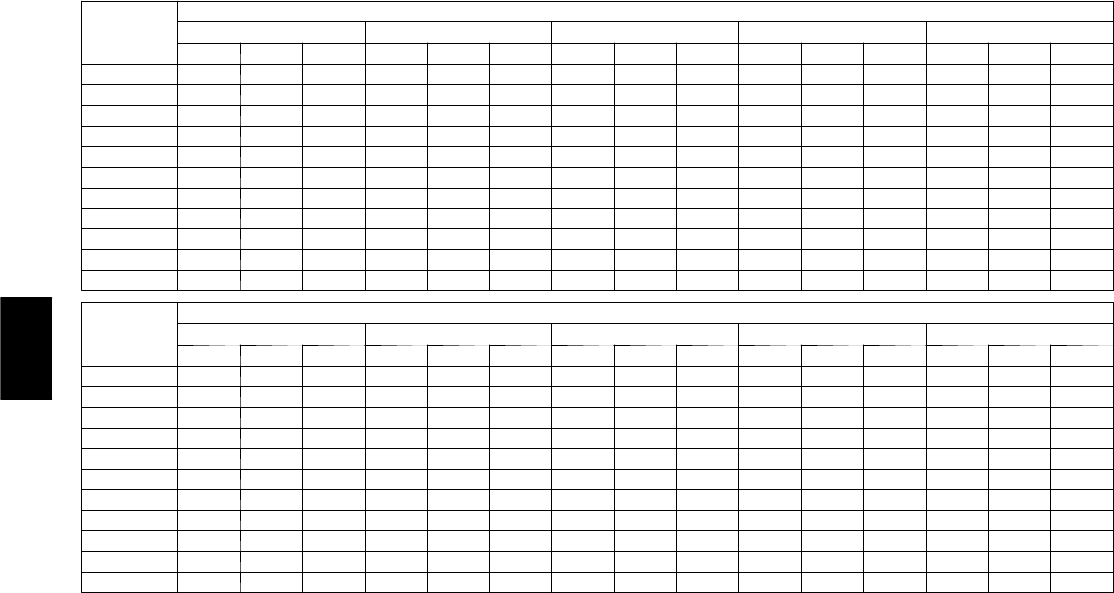
54
Table 30—Fan Performance 50HJ006, 50HE006 Single-Phase — Horizontal Discharge Units;
Standard Motor (Belt Drive)*
AIRFLOW
CFM
EXTERNAL STATIC PRESSURE (in. wg)
0.2 0.4 0.6 0.8 1.0
Rpm Bhp Watts Rpm Bhp Watts Rpm Bhp Watts Rpm Bhp Watts Rpm Bhp Watts
1500 724 0.33 295 837 0.45 402 937 0.59 524 1028 0.74 660 1111 0.91 808
1600 757 0.39 343 866 0.51 455 962 0.65 580 1050 0.81 719 1132 0.98 870
1700 790 0.45 398 894 0.58 514 988 0.72 643 1074 0.88 784 1154 1.06 938
1800 823 0.52 458 924 0.65 579 1015 0.80 712 1099 0.96 857 1177 1.14 1013
1900 857 0.59 525 955 0.73 650 1043 0.89 787 1125 1.05 936 1201 1.23 1096
2000 892 0.67 599 986 0.82 729 1072 0.98 870 1151 1.15 1022 ———
2100 927 0.77 680 1017 0.92 815 1101 1.08 960 1178 1.26 1116 ———
2200 962 0.87 769 1050 1.02 909 1131 1.19 1059 ——————
2300 997 0.97 865 1082 1.14 1010 —————————
2400 1033 1.09 970 1115 1.26 1120 —————————
2500 1069 1.22 1084 ————————————
AIRFLOW
CFM
EXTERNAL STATIC PRESSURE (in. wg)
1.2 1.4 1.6 1.8 2.0
Rpm Bhp Watts Rpm Bhp Watts Rpm Bhp Watts Rpm Bhp Watts Rpm Bhp Watts
1500 1188 1.09 970 1261 1.29 1143 —————————
1600 1208 1.16 1033 ————————————
1700 1229 1.24 1103 ————————————
1800 ———————————————
1900 ———————————————
2000 ———————————————
2100 ———————————————
2200 ———————————————
2300 ———————————————
2400 ———————————————
2500 ———————————————
NOTES:
1. Bold cells indicate field-supplied drive is required.
2. Maximum continuous bhp is 1.30.
3. See general fan performance notes.
LEGEND
Bhp — Brake Horsepower
Watts — Input Watts to Motor
*Motor drive range: 1035 to 1460 rpm. All other rpms require field-supplied
drive.
50HE,HJ
55
Table 31—Fan Performance 50HJ006, 50HE006 Three-Phase — Horizontal Discharge Units;
Standard Motor (Belt Drive)*
AIRFLOW
CFM
EXTERNAL STATIC PRESSURE (in. wg)
0.2 0.4 0.6 0.8 1.0
Rpm Bhp Watts Rpm Bhp Watts Rpm Bhp Watts Rpm Bhp Watts Rpm Bhp Watts
1500 724 0.33 295 837 0.45 402 937 0.59 524 1028 0.74 660 1111 0.91 808
1600 757 0.39 343 866 0.51 455 962 0.65 580 1050 0.81 719 1132 0.98 870
1700 790 0.45 398 894 0.58 514 988 0.72 643 1074 0.88 784 1154 1.06 938
1800 823 0.52 458 924 0.65 579 1015 0.80 712 1099 0.96 857 1177 1.14 1013
1900 857 0.59 525 955 0.73 650 1043 0.89 787 1125 1.05 936 1201 1.23 1096
2000 892 0.67 599 986 0.82 729 1072 0.98 870 1151 1.15 1022 1226 1.33 1185
2100 927 0.77 680 1017 0.92 815 1101 1.08 960 1178 1.26 1116 1251 1.44 1283
2200 962 0.87 769 1050 1.02 909 1131 1.19 1059 1206 1.37 1218 1277 1.56 1389
2300 997 0.97 865 1082 1.14 1010 1161 1.31 1165 1235 1.50 1329 1304 1.69 1503
2400 1033 1.09 970 1115 1.26 1120 1192 1.44 1279 1264 1.63 1448 1332 1.83 1625
2500 1069 1.22 1084 1149 1.39 1239 1223 1.58 1403 1293 1.77 1576 1360 1.98 1757
AIRFLOW
CFM
EXTERNAL STTIC PRESSURE (in. wg)
1.2 1.4 1.6 1.8 2.0
Rpm Bhp Watts Rpm Bhp Watts Rpm Bhp Watts Rpm Bhp Watts Rpm Bhp Watts
1500 1188 1.09 970 1261 1.29 1143 1330 1.49 1327 1395 1.71 1523 1457 1.95 1729
1600 1208 1.16 1033 1279 1.36 1208 1347 1.57 1394 1412 1.79 1590 1474 2.02 1797
1700 1229 1.24 1103 1299 1.44 1280 1366 1.65 1468 1429 1.88 1665 1490 2.11 1873
1800 1250 1.33 1181 1319 1.53 1360 1385 1.74 1549 1448 1.97 1748 1508 2.20 1957
1900 1273 1.43 1266 1341 1.63 1447 1405 1.84 1638 1467 2.07 1839 1527 2.31 2050
2000 1296 1.53 1359 1363 1.74 1542 1427 1.95 1736 1488 2.18 1939 ———
2100 1320 1.64 1459 1386 1.85 1646 1448 2.07 1842 1508 2.30 2047 ———
2200 1345 1.77 1568 1409 1.98 1758 1471 2.20 1956 ——————
2300 1371 1.90 1686 1434 2.11 1878 1494 2.34 2080 ——————
2400 1397 2.04 1812 1459 2.26 2008 —————————
2500 1424 2.19 1948 ————————————
NOTES:
1. Bold cells indicate field-supplied drive is required.
2. Maximum continuous bhp is 2.40.
3. See general fan performance notes.
LEGEND
Bhp — Brake Horsepower
Watts — Input Watts to Motor
*Motor drive range: 1035 to 1460 rpm. All other rpms require field-supplied
drive.
50HE,HJ
56
Table 32—Fan Performance 50HJ006, 50HE006 — Horizontal Discharge Units;
HIGH--STATIC Motor (Belt Drive)*
AIRFLOW
CFM
EXTERNAL STATIC PRESSURE (in. wg)
0.2 0.4 0.6 0.8 1.0
Rpm Bhp Watts Rpm Bhp Watts Rpm Bhp Watts Rpm Bhp Watts Rpm Bhp Watts
1500 724 0.33 295 837 0.45 402 937 0.59 524 1028 0.74 660 1111 0.91 808
1600 757 0.39 343 866 0.51 455 962 0.65 580 1050 0.81 719 1132 0.98 870
1700 790 0.45 398 894 0.58 514 988 0.72 643 1074 0.88 784 1154 1.06 938
1800 823 0.52 458 924 0.65 579 1015 0.80 712 1099 0.96 857 1177 1.14 1013
1900 857 0.59 525 955 0.73 650 1043 0.89 787 1125 1.05 936 1201 1.23 1096
2000 892 0.67 599 986 0.82 729 1072 0.98 870 1151 1.15 1022 1226 1.33 1185
2100 927 0.77 680 1017 0.92 815 1101 1.08 960 1178 1.26 1116 1251 1.44 1283
2200 962 0.87 769 1050 1.02 909 1131 1.19 1059 1206 1.37 1218 1277 1.56 1389
2300 997 0.97 865 1082 1.14 1010 1161 1.31 1165 1235 1.50 1329 1304 1.69 1503
2400 1033 1.09 970 1115 1.26 1120 1192 1.44 1279 1264 1.63 1448 1332 1.83 1625
2500 1069 1.22 1084 1149 1.39 1239 1223 1.58 1403 1293 1.77 1576 1360 1.98 1757
AIRFLOW
CFM
EXTERNAL STATIC PRESSURE (in. wg)
1.2 1.4 1.6 1.8 2.0
Rpm Bhp Watts Rpm Bhp Watts Rpm Bhp Watts Rpm Bhp Watts Rpm Bhp Watts
1500 1188 1.09 970 1261 1.29 1143 1330 1.49 1327 1395 1.71 1523 1457 1.95 1729
1600 1208 1.16 1033 1279 1.36 1208 1347 1.57 1394 1412 1.79 1590 1474 2.02 1797
1700 1229 1.24 1103 1299 1.44 1280 1366 1.65 1468 1429 1.88 1665 1490 2.11 1873
1800 1250 1.33 1181 1319 1.53 1360 1385 1.74 1549 1448 1.97 1748 1508 2.20 1957
1900 1273 1.43 1266 1341 1.63 1447 1405 1.84 1638 1467 2.07 1839 1527 2.31 2050
2000 1296 1.53 1359 1363 1.74 1542 1427 1.95 1736 1488 2.18 1939 1546 2.42 2151
2100 1320 1.64 1459 1386 1.85 1646 1448 2.07 1842 1508 2.30 2047 1566 2.55 2262
2200 1345 1.77 1568 1409 1.98 1758 1471 2.20 1956 1530 2.44 2164 1587 2.68 2380
2300 1371 1.90 1686 1434 2.11 1878 1494 2.34 2080 1553 2.58 2290 1609 2.83 2509
2400 1397 2.04 1812 1459 2.26 2008 1518 2.49 2213 1576 2.73 2425 ———
2500 1424 2.19 1948 1484 2.42 2147 1543 2.65 2355 1599 2.89 2571 ———
NOTES:
1. Bold cells indicate field-supplied drive is required.
2. Maximum continuous bhp is 2.90.
3. See general fan performance notes.
LEGEND
Bhp — Brake Horsepower
Watts — Input Watts to Motor
*Motor drive range: 1300 to 1685 rpm. All other rpms require field-supplied
drive.
Table 33—Fan Performance 50HJ007 — Horizontal Discharge Units; Standard Motor (Belt Drive)*
AIRFLOW
CFM
EXTERNAL STATIC PRESSURE (in. wg)
0.2 0.4 0.6 0.8 1.0
Rpm Bhp Watts Rpm Bhp Watts Rpm Bhp Watts Rpm Bhp Watts Rpm Bhp Watts
1800 822 0.51 455 927 0.66 589 1018 0.82 728 1100 0.98 873 1174 1.15 1024
1900 855 0.59 520 957 0.74 659 1046 0.91 805 1127 1.08 956 1200 1.25 1113
2000 889 0.66 591 988 0.83 737 1075 1.00 888 1154 1.18 1045 1226 1.36 1208
2100 923 0.75 668 1019 0.92 821 1104 1.10 979 1182 1.29 1142 1253 1.48 1310
2200 957 0.85 753 1051 1.03 912 1134 1.21 1077 1210 1.40 1245 1280 1.60 1419
2300 992 0.95 845 1083 1.14 1011 1164 1.33 1182 1239 1.53 1357 1308 1.73 1537
2400 1026 1.06 945 1115 1.26 1118 1195 1.46 1295 1268 1.66 1476 1336 1.87 1662
2500 1061 1.19 1053 1148 1.39 1233 1226 1.59 1416 1297 1.81 1604 1364 2.02 1796
2600 1097 1.32 1169 1181 1.53 1356 1257 1.74 1546 1327 1.96 1740 1393 2.18 1938
2700 1132 1.46 1294 1214 1.67 1487 1289 1.90 1684 1358 2.12 1885 1422 2.35 2089
2800 1168 1.61 1428 1247 1.83 1629 1320 2.06 1832 1388 2.30 2039 — — —
2900 1204 1.77 1572 1281 2.00 1779 1353 2.24 1989 ——————
3000 1240 1.94 1725 1315 2.18 1939 —————————
AIRFLOW
CFM
EXTERNAL STATIC PRESSURE (in. wg)
1.2 1.4 1.6 1.8 2.0
Rpm Bhp Watts Rpm Bhp Watts Rpm Bhp Watts Rpm Bhp Watts Rpm Bhp Watts
1800 1244 1.33 1182 1308 1.51 1345 1369 1.70 1513 1427 1.90 1687 1483 2.10 1867
1900 1268 1.44 1275 1332 1.63 1443 1393 1.82 1617 1450 2.02 1796 1505 2.23 1979
2000 1294 1.55 1376 1357 1.74 1549 1417 1.95 1727 1474 2.15 1911 1528 2.36 2100
2100 1320 1.67 1483 1382 1.87 1662 1441 2.08 1845 1498 2.29 2034 — — —
2200 1346 1.80 1598 1408 2.01 1782 1466 2.22 1971 ——————
2300 1372 1.94 1721 1434 2.15 1911 1491 2.37 2105 ——————
2400 1400 2.09 1852 1460 2.31 2047 —————————
2500 1427 2.24 1992 ————————————
2600 ———————————————
2700 ———————————————
2800 ———————————————
2900 ———————————————
3000 ———————————————
NOTES:
1. Bold cells indicate field-supplied drive is required.
2. Maximum continuous bhp is 2.40.
3. See general fan performance notes.
LEGEND
Bhp — Brake Horsepower
Watts — Input Watts to Motor
*Motor drive range: 1120 to 1585 rpm. All other rpms require field-supplied
drive.
50HE,HJ
57
Table 34—Fan Performance 50HJ007 — Horizontal Discharge Units; High-Static Motor (Belt Drive)*
AIRFLOW
CFM
EXTERNAL STATIC PRESSURE (in. wg)
0.2 0.4 0.6 0.8 1.0
Rpm Bhp Watts Rpm Bhp Watts Rpm Bhp Watts Rpm Bhp Watts Rpm Bhp Watts
1800 822 0.51 455 927 0.66 589 1018 0.82 728 1100 0.98 873 1174 1.15 1024
1900 855 0.59 520 957 0.74 659 1046 0.91 805 1127 1.08 956 1200 1.25 1113
2000 889 0.66 591 988 0.83 737 1075 1.00 888 1154 1.18 1045 1226 1.36 1208
2100 923 0.75 668 1019 0.92 821 1104 1.10 979 1182 1.29 1142 1253 1.48 1310
2200 957 0.85 753 1051 1.03 912 1134 1.21 1077 1210 1.40 1245 1280 1.60 1419
2300 992 0.95 845 1083 1.14 1011 1164 1.33 1182 1239 1.53 1357 1308 1.73 1537
2400 1026 1.06 945 1115 1.26 1118 1195 1.46 1295 1268 1.66 1476 1336 1.87 1662
2500 1061 1.19 1053 1148 1.39 1233 1226 1.59 1416 1297 1.81 1604 1364 2.02 1796
2600 1097 1.32 1169 1181 1.53 1356 1257 1.74 1546 1327 1.96 1740 1393 2.18 1938
2700 1132 1.46 1294 1214 1.67 1487 1289 1.90 1684 1358 2.12 1885 1422 2.35 2089
2800 1168 1.61 1428 1247 1.83 1629 1320 2.06 1832 1388 2.30 2039 1452 2.53 2249
2900 1204 1.77 1572 1281 2.00 1779 1353 2.24 1989 1419 2.48 2202 1482 2.72 2419
3000 1240 1.94 1725 1315 2.18 1939 1385 2.43 2156 1451 2.68 2376 ———
AIRFLOW
CFM
EXTERNAL STATIC PRESSURE (in. wg)
1.2 1.4 1.6 1.8 2.0
Rpm Bhp Watts Rpm Bhp Watts Rpm Bhp Watts Rpm Bhp Watts Rpm Bhp Watts
1800 1244 1.33 1182 1308 1.51 1345 1369 1.70 1513 1427 1.90 1687 1483 2.10 1867
1900 1268 1.44 1275 1332 1.63 1443 1393 1.82 1617 1450 2.02 1796 1505 2.23 1979
2000 1294 1.55 1376 1357 1.74 1549 1417 1.95 1727 1474 2.15 1911 1528 2.36 2100
2100 1320 1.67 1483 1382 1.87 1662 1441 2.08 1845 1498 2.29 2034 1552 2.51 2227
2200 1346 1.80 1598 1408 2.01 1782 1466 2.22 1971 1522 2.44 2165 1575 2.66 2363
2300 1372 1.94 1721 1434 2.15 1911 1491 2.37 2105 1547 2.59 2304 1600 2.82 2507
2400 1400 2.09 1852 1460 2.31 2047 1517 2.53 2247 1572 2.76 2451 ———
2500 1427 2.24 1992 1487 2.47 2192 1543 2.70 2398 ——————
2600 1455 2.41 2140 1514 2.64 2346 1570 2.88 2557 ——————
2700 1483 2.59 2297 1541 2.83 2509 —————————
2800 1512 2.77 2463 ————————————
2900 1541 2.97 2640 ————————————
3000 ———————————————
NOTES:
1. Bold cells indicate field-supplied drive is required.
2. Maximum continuous bhp is 2.90.
3. See general fan performance notes.
LEGEND
Bhp — Brake Horsepower
Watts — Input Watts to Motor
*Motor drive range: 1300 to 1685 rpm. All other rpms require field-supplied
drive.
50HE,HJ

58
PRE-START-UP
FIRE, EXPLOSION, ELECTRICAL SHOCK HAZARD
Failure to follow this warning could result in personal
injury, death, and/or property damage.
1. Follow recognized safety practices and wear protective
goggles when checking or servicing a refrigerant system.
2. Do not operate the compressor or provide any electric
power to the unit unless the compressor terminal cover is
in place and secured.
3. Do not remove the compressor terminal cover until all
electrical sources are disconnected and tagged with lockout
tags.
4. Relieve all pressure from the system before touching or
disturbing anything inside the terminal box if a
refrigerant leak is suspected around the compressor
terminals. Use accepted methods to recover the
refrigerant.
5. Never attempt to repair a soldered connection while the
refrigerant system is under pressure.
6. Do not use a torch to remove any component. The
system contains oil and refrigerant under pressure. To
remove a component, wear protective goggles and proceed
as follows:
a. Shut off electrical power to the unit and tag
disconnect.
b. Recover refrigerant to relieve all pressure
from the system using both high-pressure
and low-pressure ports.
c. Cut component connection tubing with a
tubing cutter, and remove the component
from the unit.
d. Carefully unsweat the remaining tubing
stubs when necessary. Oil can ignite when
exposed to a torch flame.
!WARNING
Proceed as follows to inspect and prepare the unit for initial
start-up:
1. Remove all access panels.
2. Read and follow instructions on all WARNING,
CAUTION, and INFORMATION labels attached to, or
shipped with, unit.
3. Make the following inspections:
a. Inspect for shipping and handling damages such as
broken lines, loose parts, or disconnected wires, etc.
b. Inspect for oil at all refrigerant tubing connections and on
unit base. Detecting oil generally indicates a refrigerant
leak. Leak-test all refrigerant tubing connections using
electronic leak detector, halide torch, or liquid-soap
solution.
c. Inspect all field-wiring and factory-wiring connections.
Be sure that connections arecompleted and tight. Be sure
that wires are not in contact with refrigerant tubing or
sharp edges.
d. Inspect coil fins. If damaged during shipping and
handling, carefully straighten fins with a fin comb.
4. Verify the following conditions:
a. Make sure that condenser-fan blade are correctly
positioned in fan orifice.See Condenser-Fan Adjustment
section for more details.
b. Make sure that air filter(s) is in place.
c. Make sure that condensate drain trap is filled with water
to ensure proper drainage.
d. Make sure that all tools and miscellaneous loose parts
have been removed.
START-UP
Step 1 —Unit Preparation
Make sure that the unit has been installed in accordance with
installation instructions and applicable codes.
Step 2 —Return--Air Filters
Make sure the correct filters are installed in the unit (See Table 1).
Do not operate the unit without return-air filters.
Step 3 —Outdoor--Air Inlet Screens
Outdoor-air inlet screen(s) must be in place before operating the
unit.
Step 4 —Compressor Mounting
Compressors are internally spring mounted. Do not loosen or
remove the compressor holddown bolts.
Step 5 —Internal Wiring
Check all electrical connections in unit control boxes; tighten
them as required.
Step 6 —Refrigerant Service Ports
Each unit system has 4 Schrader--type service ports: one on the
suction line, one on the liquid line, and 2 on the compressor
discharge line. Be sure that caps on the ports are tight.
Step 7 —High Flow Valves
Two high flow refrigerant valves are located on the hot gas tube
coming out of the compressor and the suction tubes. Large black
plastic caps distinguish these valves with O--rings located inside
the caps. No field access to these valves is available at this time.
Ensure the plastic caps are in place and tight or the possibility of
refrigerant leakage could occur.
Step 8 —Compressor Rotation
On 3-phase units be certain that the compressor is rotating in the
proper direction. To determine whether or not compressor is
rotating in the proper direction:
1. Connect the service gauges to suction and discharge
pressure fittings.
2. Energize the compressor.
3. The suction pressure should drop and the discharge
pressure should rise, as is normal on any start-up.
If the suction pressure does not drop and the discharge pressure
does not rise to normal levels:
1. Note that the indoor fan (006 and 007 three-phase units
only) is probably also rotating in the wrong direction.
2. Turn off power to the unit and tag disconnect.
3. Reverse any two of the unit power leads.
4. Turn on power to the unit and energize the compressor.
The suction and discharge pressure levels should now move to
their normal start-up levels.
NOTE: When the compressor is rotating in the wrong direction,
the unit makes more noise and does not provide cooling.
Step 9 —Cooling
Set the space thermostat to the OFF position. Set the system
selector switch at COOL position and the fan switch at AUTO
position. Adjust the thermostat to a setting below room
temperature. The compressor starts when contactor closes.
Check cooling effects at a setting below room temperature.
Check the unit charge. Refer to Refrigerant Charge section.
Reset the thermostat at a position above room temperature. The
compressor will shut off.
To Shut Off Unit -- Set the system selector switch at OFF
position. Resetting the thermostat at a position above room
temperature shuts off the unit temporarily until the space
temperature exceeds the thermostat setting. Units are equipped
50HE,HJ

59
with a Cycle-LOCprotection device. The unit shuts down on
any safety trip and remains off; an indicator light on the
thermostat comes on. Check the reason for the safety trip.
Compressor restart is accomplished by manual reset at the
thermostat by turning the selector switch to OFF position and
then to ON position.
Step 10 —Heating
To start unit, turn on main power supply.
Set system selector switch at HEAT position and set thermostat at
a setting above room temperature. Set fan at AUTO position.
First stage of thermostat energizes the first--stage electric heater
elements; second stage energizes second--stage electric heater
elements, if installed. Check heating effects at air supply grille(s).
If electric heaters do not energize, reset limit switch (located on
evaporator--fan scroll) by pressing button located between
terminals on the switch.
TO SHUT OFF UNIT -- Set system selector switch at OFF
position. Resetting thermostat at a position below room
temperature temporarily shuts unit off until space temperature
falls below thermostat setting.
Step 11 —Safety Relief
A soft solder joint at the suction line fitting provides pressure
relief under abnormal temperature and pressure conditions.
Step 12 —Ventilation (Continuous Fan)
Set fan and system selector switches at ON and OFF positions,
respectively. Evaporator fan operates continuously to provide
constant air circulation.
Step 13 —Operating Sequence
Cooling -- Units Without Economizer
When thermostat calls for cooling, terminals G and Y1 are
energized. The indoor-fan contactor (IFC), reversing valve
solenoid (RVS) and compressor contactor are energized and
indoor-fan motor, compressor, and outdoor fan starts. The
outdoor fan motor runs continuously while unit is cooling.
Heating -- Units Without Economizer
When the thermostat calls for heating, terminal W1 will be
energized with 24v. The IFC and heater contactor no. 1 (HC1)
are energized.
Cooling -- Units With Economi$er IV
When free cooling is not available, the compressors will be
controlled by the zone thermostat. When free cooling is available,
the outdoor-air damper is modulated by the EconoMi$er IV
control to provide a 50_to 55_F supply-air temperature into the
zone. As the supply-air temperature fluctuates above 55_or
below 50_F, the dampers will be modulated (open or close) to
bring the supply-air temperature back within the set point limits.
Integrated EconoMi$er IV operation on single-stage units
requires a 2-stage thermostat (Y1 and Y2).
For EconoMi$er IV operation, there must be a thermostat call for
the fan (G). This will move the damper to its minimum position
during the occupied mode.
If the increase in cooling capacity causes the supply--air
temperature to drop below 45_F, then the outdoor--air damper
position will be fully closed. If the supply--air temperature
continues to fall, the outdoor--air damper will close. Control
returns to normal once the supply--air temperature rises above
48_F.
If optional power exhaust is installed, as the outdoor--air damper
opens and closes, the power exhaust fans will be energized and
deenergized.
If field--installed accessory CO2sensors are connected to the
EconoMi$er IV control, a demand controlled ventilation strategy
will begin to operate. As the CO2level in the zone increases
above the CO2set point, the minimum position of the damper
will be increased proportionally. As the CO2level decreases
because of the increase in fresh air, the outdoor--air damper will
be proportionally closed. Damper position will follow the higher
demand condition from DCV mode or free cooling mode.
Damper movement from full closed to full open (or vice versa)
will take between 1--1/2 and 2--1/2 minutes.
If free cooling can be used as determined from the appropriate
changeover command (switch, dry bulb, enthalpy curve,
differential dry bulb, or differential enthalpy), a call for cooling
(Y1 closes at the thermostat) will cause the control to modulate
the dampers open to maintain the supply air temperature set point
at 50_to 55_F.
As the supply air temperature drops below the set point range of
50_to 55_F, the control will modulate the outdoor--air dampers
closed to maintain the proper supply--air temperature.
Heating -- Units With Economi$er IV
When the room temperature calls for heat, the heating controls are
energized as described in the Heating, Units Without Economizer
section. When the thermostat is satisfied, the economizer damper
moves to the minimum position.
Cooling -- Units With Economi$er2, PremierlinktControl
and a Thermostat
When free cooling is not available, the compressors will be
controlled by the PremierLink control in response to the Y1 and
Y2 inputs from the thermostat.
The PremierLink control will use the following information to
determine if free cooling is available:
SIndoor fan has been on for at least 30 seconds.
SThe SPT, SAT, and OAT inputs must have valid
readings.
SOAT must be less than 75_F.
SOAT must be less than SPT.
SEnthalpy must be LOW (may be jumpered if an
enthalpy sensor not available).
SEconomizer position is NOT forced.
Pre-cooling occurs when there is no call from the thermostat
except G. Pre-cooling is defined as the economizer modulates to
provide 70_F supply air.
When free cooling is available the PremierLink control will
control the compressors and economizer to provide a supply-air
temperature determined to meet the Y1 and Y2 calls from the
thermostat using the following three routines. The three control
routines are based on OAT.
The 3 routines are based on OAT where:
SASP = Supply Air Set Point
DXCTLO = Direct Expansion Cooling Lockout Set Point
PID = Proportional Integral
Routine 1 (OAT < DXCTLO)
SY1 energized – economizer maintains a SASP =
(SATLO1 + 3).
SY2 energized – economizer maintains a SASP =
(SATLO2 + 3).
Routine 2 (DXCTLO<OAT<68_F)
SIf only Y1 energized, the economizer maintains a
SASP = (SATLO1 + 3).
SIf SAT > SASP + 5 and economizer position > 80%,
economizer will go to minimum position for 3 minutes
or until SAT > 68_F.
SFirst stage of mechanical cooling will be energized.
SIntegrator resets.
SEconomizer opens again and controls to current SASP
after stage one on for 90 seconds.
50HE,HJ
60
SWith Y1 and Y2 energized Economizer maintains an
SASP = SATLO2 + 3.
SIf SAT > SASP + 5 and economizer position >80%,
economizer will go to minimum position for 3 minutes
or until SAT > 68_F.
SIf compressor one is on then second stage of
mechanical cooling will be energized; otherwise the
first stage will be energized.
SIntegrator resets.
SEconomizer opens again and controls to SASP after
stage one on for 90 seconds.
Routine 3 (OAT > 68)
SEconomizer is opened 100%.
SCompressors1and2arecycledbasedonY1andY2
using minimum on and off times and watching the
supply air temperature as compared to SATLO1 and
SATLO2 set points.
If optional power exhaust is installed, as the outdoor-air damper
opens and closes, the power exhaust fans will be energized and
deenergized.
If field-installed accessory CO2sensors are connected to the
PremierLinkcontrol, a PID-controlled demand ventilation
strategy will begin to operate. As the CO2level in the zone
increases above the CO2set point, the minimum position of the
damper will be increased proportionally. As the CO2level
decreases because of the increase in fresh air, the outdoor-air
damper will be proportionally closed.
Heating -- Units With Economi$er2 Premierlink Control and
aThermostat
When the thermostat calls for heating, terminal W1 is energized.
The PremierLink control will move the economizer damper to the
minimum position if there is a call for G and closed if there is a
call for W1 without G. The IFC and heater contactor no. 1 (HC1)
are energized. When the thermostat is satisfied and W1 is
deenergized, the IFM stops after a 45--second time--off delay
unless G is still maintained.
Cooling -- Units With Economi$er2, Premierlink Control and
a Room Sensor
When free cooling is not available, the compressors will be
controlled by the PremierLink controller using a PID Error
reduction calculation as indicated by Fig 49.
The PremierLink controller will use the following information to
determine if free cooling is available:
SIndoor fan has been on for at least 30 seconds.
SThe SPT, SAT, and OAT inputs must have valid
readings.
SOAT must be less than 75_F.
SOAT must be less than SPT.
SEnthalpy must be LOW (may be jumpered if and
enthalpy sensor is not available).
SEconomizer position is NOT forced.
68
69
70
71
72
73
74
75
SPACE TEMPERATURE
TIME
TEMPERATURE CONTROL
SET POINT
TEMPERATURE
NOTE: PremierLink control performs smart staging of 2 stages of DX
cooling and up to 3 stages of heat.
C06042
Fig. 49 --- DX Cooling Temperature
Control Example
68
69
70
71
72
73
74
75
SPACE TEMPERATURE
TIME
TEMPERATURE CONTROL
COOL SETPOINT
TEMPERATURE
HEAT SETPOINT
C06043
Fig. 50 --- Economizer Temperature
Control Example
When free cooling is available, the outdoor-air damper is
positioned through the use of a Proportional Integral (PID)
control process to provide a calculated supply-air temperature
into the zone. The supply air will maintain the space temperature
between the heating and cooling set points as indicated in Fig. 50.
The PremierLink control will integrate the compressors stages
with the economizer based on similar logic as the three routines
listed in the previous section. The SASP will float up and down
based on the error reduction calculations that compare space
temperature and space set point.
When outside-air temperature conditions require the economizer
to close for a compressor stage-up sequence, the economizer
control integrator is reset to zero after the stage-up sequence is
completed. This prevents the supply-air temperature from
dropping too quickly and creating a freeze condition that would
make the compressor turn off prematurely.
The high space set point is used for DX (direct expansion)
cooling control, while the economizer space set point is a
calculated value between the heating and cooling set points. The
economizer set point will always be at least one degree below the
cooling set point, allowing for a smooth transition from
mechanical cooling with economizer assist, back to economizer
cooling as the cooling set point is achieved. The compressors
may be used for initial cooling then the PremierLink controller
will modulate the economizer using an error reduction calculation
to hold the space temperature between the heating and cooling set
points. (See Fig. 50.)
The controller uses the following conditions to determine
economizer cooling:
SEnthalpy is Low
SSAT reading is available
SOAT reading is available
50HE,HJ
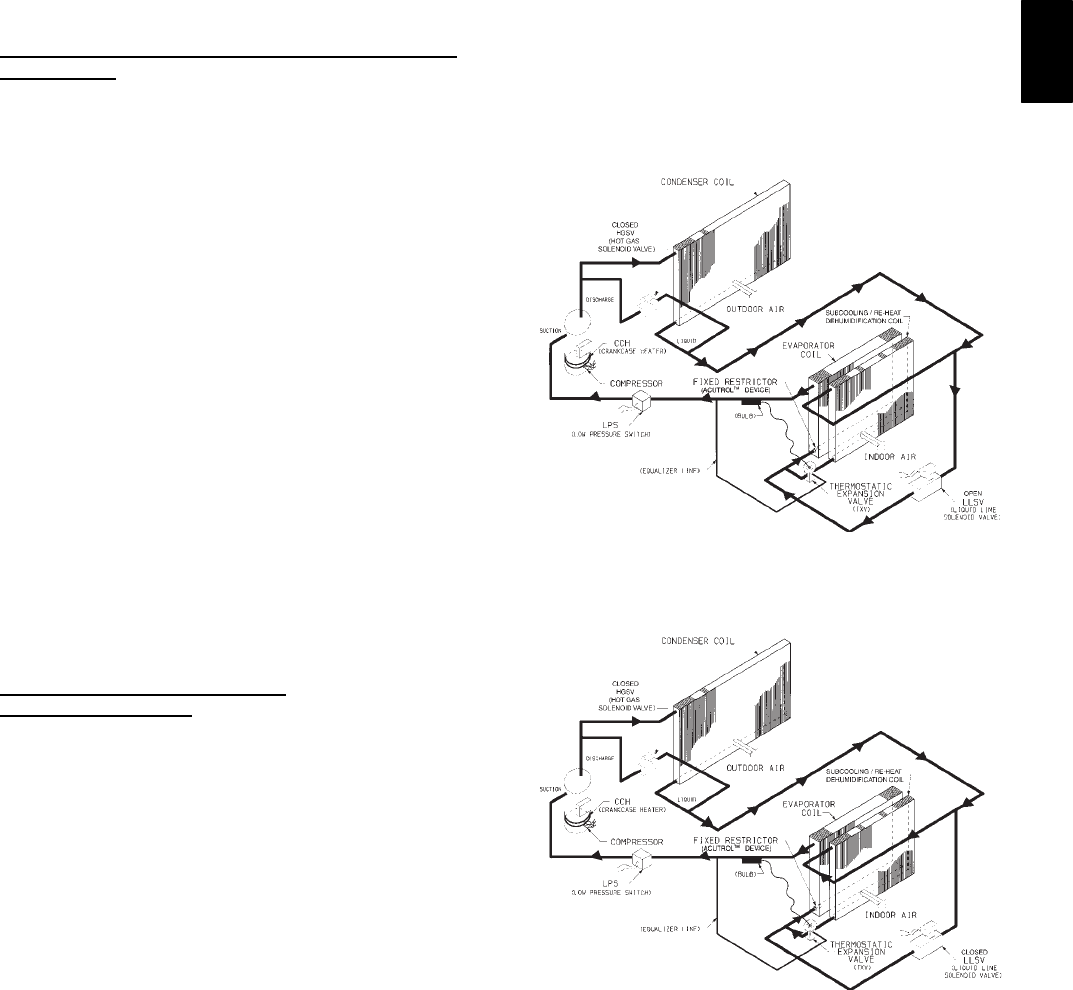
61
SSPT reading is available
SOAT ±SPT
SEconomizer Position is NOT forced
If any of the above conditions are not met, the economizer
submaster reference (ECSR) is set to maximum limit and the
damper moves to minimum position. The operating sequence is
complete. The ECSR is recalculated every 30 seconds.
If an optional power exhaust is installed, as the outdoor-air
damper opens and closes, the power exhaust fans will be
energized and deenergized.
If field-installed accessory CO2sensors are connected to the
PremierLinkcontrol, a PID-controlled demand ventilation
strategy will begin to operate. As the CO2level in the zone
increases above the CO2set point, the minimum position of the
damper will be increased proportionally. As the CO2level
decreases because of the increase in fresh air, the outdoor-air
damper will be proportionally closed.
Heating -- Unit With Economi$er2, Premierlink Control and
a Room Sensor
Every 40 seconds the controller will calculate the required heat
stages (maximum of 3) to maintain Supply-Air Temperature
(SAT) if the following qualifying conditions are met:
SIndoor fan has been on for at least 30 seconds.
SCOOL mode is not active.
SOCCUPIED, TEMP. COMPENSATED START or
HEAT mode is active.
SSAT reading is available.
SFire shutdown mode is not active.
If all of the above conditions are met, the number of heat stages is
calculated; otherwise the required number of heat stages will be
set to 0.
If the PremierLink controller determines that heat stages are
required, the economizer damper will be moved to minimum
position if occupied and closed if unoccupied.
Staging should be as follows:
If Heating PID STAGES=2
SHEAT STAGES=1 (50% capacity) will energize HS1
SHEAT STAGES=2 (100% capacity) will energize HS2
If Heating PID STAGES=3 and AUXOUT = HS3
SHEAT STAGES=1 (33% capacity) will energize HS1
SHEAT STAGES=2 (66% capacity) will energize HS2
SHEAT STAGES=3 (100% capacity) will energize HS3
Units With Humidi-MizerAdaptive
Dehumidification System
Normal Design Operation
When the rooftop operates under the normal sequence of
operation, the compressors will cycle to maintain indoor
conditions. (See Fig. 51.)
The Humidi-MiZer adaptive dehumidification system includes a
factory-installed Motormasterlow ambient control to keep the
head and suction pressure high, allowing normal design cooling
mode operation down to 0F.
Subcooling Mode
When subcooling mode is initiated, this will energize (close) the
liquid line solenoid valve (LLSV) forcing the hot liquid
refrigerant to enter into the subcooling coil. (See Fig. 52.)
As the hot liquid refrigerant passes through the subcooling/ reheat
dehumidification coil, it is exposed to the cold supply airflow
coming through the evaporator coil. The liquid is further
subcooled to a temperature approaching the evaporator
leaving-air temperature. The liquid then enters a thermostatic
expansion valve (TXV) where the liquid drops to a lower
pressure. The TXV does not have a pressure drop great enough to
change the liquid to a 2-phase fluid, so the liquid then enters the
Acutroldevice at the evaporator coil.
The liquid enters the evaporator coil at a temperature lower than
in standard cooling operation. This lower temperature increases
the latent capacity of the rooftop unit. The refrigerant passes
through the evaporator and is turned into a vapor. The air passing
over the evaporator coil will become colder than during normal
operation. However, as this same air passes over the subcooling
coil, it will be slightly warmed, partially reheating the air.
Subcooling mode operates only when the outside air
temperature is warmer than 40_F. A factory-installed temperature
switch located in the condenser section will lock out subcooling
mode when the outside temperature is cooler than 40_F.
The scroll compressors are equipped with crankcase heaters to
provide protection for the compressors due to the additional
refrigerant charge required by the subcooling/reheat coil.
When in subcooling mode, there is a slight decrease in system
total gross capacity (5% less), a lower gross sensible capacity
(20% less), and a greatly increased latent capacity (up to 40%
more).
C06135
Fig. 51 --- Humidi--MiZer Normal
Design Cooling Operation
C06136
Fig. 52 --- Humidi--MiZer Subcooling
Mode Operation
50HE,HJ
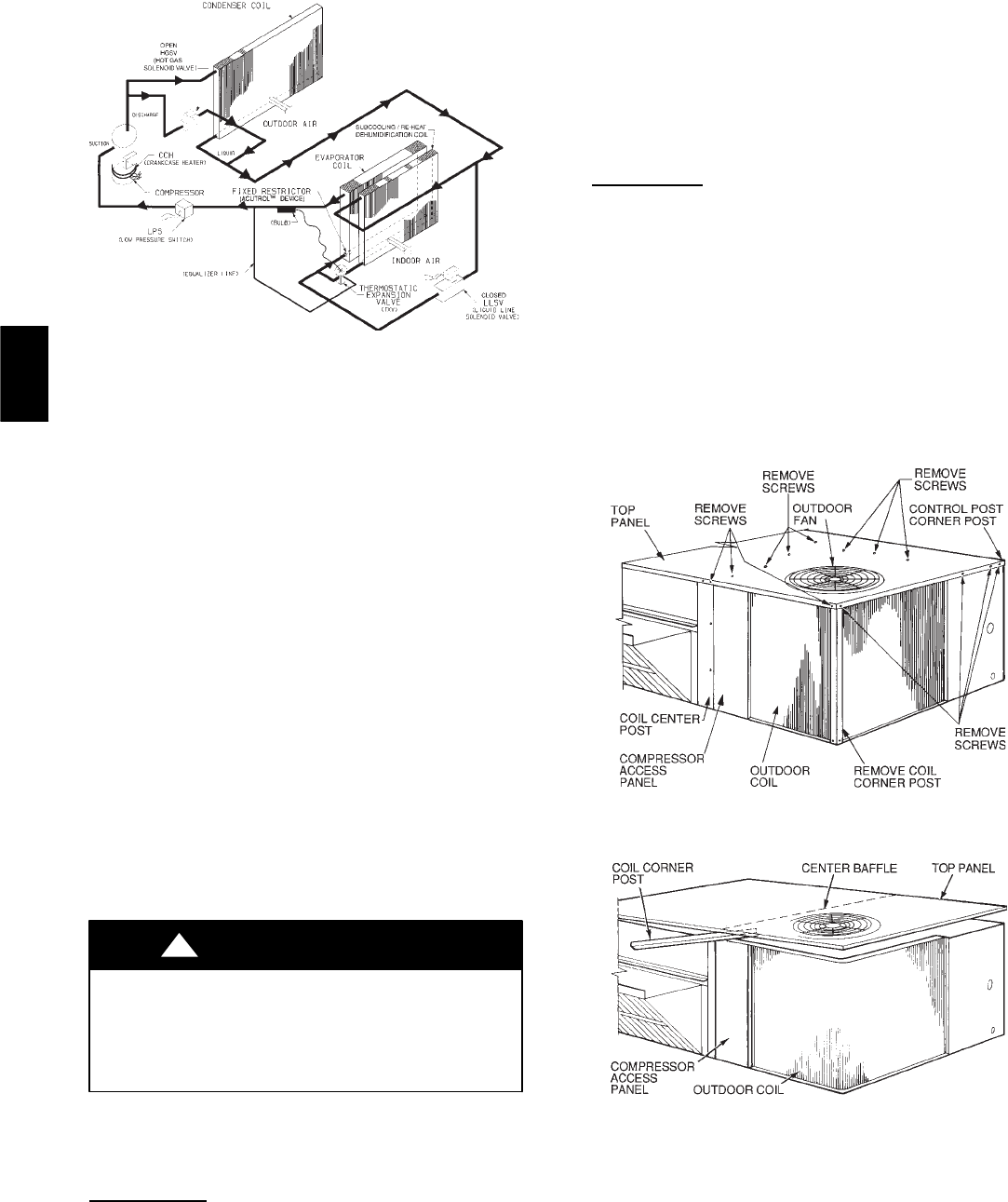
62
C06137
Fig. 53 --- Humidi--MizertHot Gas
Reheat Mode Operation
Hot Gas Reheat Mode
When the humidity levels in the space require humidity control, a
hot gas solenoid valve (specific to hot gas reheat mode only) will
open to bypass a portion of hot gas refrigerant around the
condenser coil. (See Fig. 53.)
This hot gas will mix with liquid refrigerant leaving the
condenser coil and flow to the subcooling/reheat
dehumidification coil. Now the conditioned air coming off the
evaporator will be cooled and dehumidified, but will be warmed
to neutral conditions (72_Fto75_F) by the subcooling/reheat
dehumidification coil.
The net effect of the rooftop when in hot gas reheat mode is to
provide nearly all latent capacity removal from the space when
sensible loads diminish (when outdoor temperature conditions are
moderate). When in hot gas reheat mode, the unit will operate to
provide mostly latent capacity and extremely low sensible heat
ratio capability.
Similar to the subcooling mode of operation, hot gas reheat mode
operates only when the outside air temperature is warmer than
40_F. Below this temperature, a factory installed outside air
temperature switch will lockout this mode of operation.
See Table 36 for the Humidi-Mizer adaptive dehumidification
system sequence of operation.
SERVICE
ELECTRICAL SHOCK HAZARD
Failure to follow this warning could cause personal
injury or death.
When sevicing unit, shut off all electrical power to unit
and install lockout tag.
!WARNING
Step 1 —Cleaning
Inspect unit interior at the beginning of heating and cooling
season and as operating conditions require.
Evaporator Coil
1. Turn unit power off, tag disconnect. Remove evaporator
coil access panel.
2. If economizer or two-position damper is installed, remove
economizer by disconnecting Molex plug and
removing mounting screws.
3. Slide filters out of unit.
4. Clean coil using a commercial coil cleaner or dishwasher
detergent in a pressurized spray canister. Wash both sides
of coil and flush with clean water. For best results,
back-flush toward return-air section to remove foreign
material. Flush condensate pan after completion.
5. Reinstall economizer and filters.
6. Reconnect wiring.
7. Replace access panels.
Condenser Coil
Inspect coil monthly. Clean condenser coil annually, and as
required by location and outdoor air conditions.
One--Row Coil
Wash coil with commercial coil cleaner. It is not necessary to
remove top panel.
2-Row Coils
Clean coil as follows:
1. Turn off unit power and tag disconnect.
2. Remove top panel screws on condenser end of unit.
3. Remove condenser coil corner post. (See Fig. 54.) To hold
top panel open, place coil corner post between top panel
and center post. (See Fig. 55.)
C06044
Fig. 54 --- Cleaning Condenser Coil
C06045
Fig. 55 --- Propping Up Top Panel
50HE,HJ
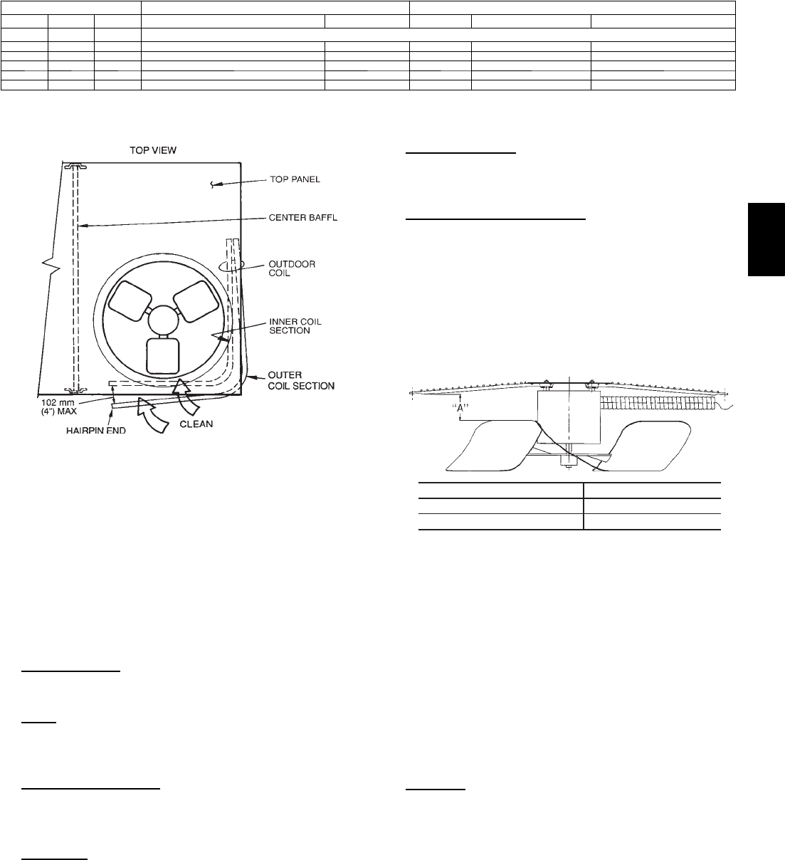
63
Table 35—Humidi-Mizer Adaptive Dehumidification System Sequence of Operation and
System Response — Single Compressor Unit (50HE003--006, 50HJ004-007)
THERMOSTAT INPUT ECONOMIZER FUNCTION 48HE, HJ UNIT OPERATION
HY1 Y2 OAT. < Economizer Set Point Economizer Comp. 1 Subcooling Mode Hot Gas Reheat Mode
Off — — Normal Operation
On On On No Off On Yes No
On On Off No Off On Yes No
On On On Yes On On Yes No
On On Off Yes On On No Yes
On Off Off No Off On No Yes
NOTE: On a thermostat call for W1, all cooling and dehumidification will be off.
LEGEND
OAT --- Outdoor Air Temperature
C06046
Fig. 56 --- Separating Coil Sections
4. Remove device holding coil sections together at return end
of condenser coil. Carefully separate the outer coil section
3 to 4 in. from the inner coil section. (See Fig. 57.)
5. Use a water hose or other suitable equipment to flush
down between the 2 coil sections to remove dirt and
debris. Clean the outer surfaces with a stiff brush in the
normal manner.
6. Secure the sections together. Reposition the outer coil
section and remove the coil corner post from between the
top panel and center post. Install the coil corner and center
posts. Replace all screws.
Condensate Drain
Check and clean each year at the start of the cooling season. In
winter, keep the drain dry or protect it against freeze-up.
Filters
Clean or replace at the start of each heating and cooling season, or
more often if operating conditions require it. Replacement filters
must be the same dimensions as the original filters.
Outdoor--Air Inlet Screen
Clean the screen with steam or hot water and a mild detergent. Do
not use disposable filters in place of screens.
Step 2 —Lubrication
Compressor
The compressor is charged with the correct amount of oil at the
factory.
Fan Motor Bearings
Fan motor bearings are permanently lubricated. No further
lubrication is required. No lubrication of condenser-fan or
evaporator-fan motors is required.
Evaporator Fan Belt Adjustment
Inspect evaporator fan belt for wear, proper belt tension, and
pulley alignment as conditions require or at the beginning of each
heating and air conditioning season. Refer to Step 7 -- Adjust
Evaporator Fan Speed for adjustment and alignment procedures.
Step 3 —Condenser--Fan Adjustment
Shut off unit power supply. Remove condenser-fan assembly
(grille, motor, motor cover, and fan) and loosen fan hub
setscrews. Adjust fan height as shown in Fig. 57. Tighten
setscrews and replace condenser-fan assembly.
UNIT FAN HEIGHT (in.) — “A”
003-006 AND 007 (208/230 v) 2.75
007 (460 v) 3.50
C06138
Fig. 57 --- Condenser--Fan Adjustment
Step 4 —EconoMi$er IV Adjustment
Refer to Optional EconoMi$er IV and EconoMi$er2 section.
Step 5 —Refrigerant Charge
Amount of refrigerant charge is listed on unit nameplate (also
refer to Table 1). Refer to HVAC Servicing Procedures literature
available at your local distributor and the following procedures.
Unit panels must be in place when unit is operating during
charging procedure. Unit must operate a minimum of 10 minutes
before checking or adjusting refrigerant charge.
No Charge
Use standard evacuating techniques. After evacuating system to
500 microns, weigh in the specified amount of refrigerant. (Refer
to Table 1 and unit information plate.)
50HE,HJ
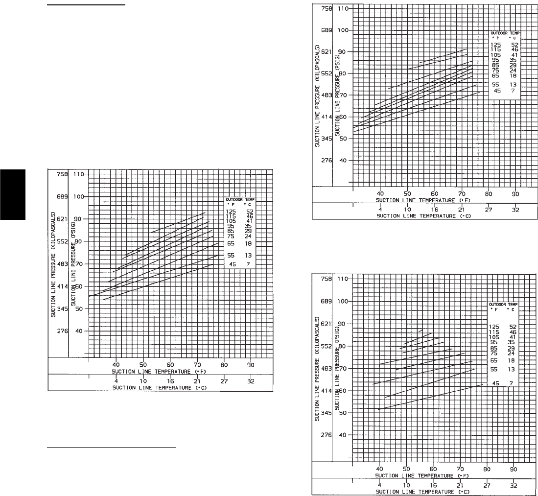
64
Low Charge Cooling
Using Cooling Charging Charts, Fig. 58--61, vary refrigerant
until the conditions of the charts are met. Note the charging charts
are different from type normally used. Charts are based on
charging the units to the correct superheat for the various
operating conditions. Accurate pressure gage and temperature
sensing device are required. Connect the pressure gauge to the
service port on the suction line. Mount the temperature sensing
device on the suction line and insulate it so that outdoor ambient
temperature does not affect the reading. Indoor-air cfm must be
within the normal operating range of the unit. An accurate
superheat, thermocouple--type or thermistor--type thermometer,
and a gauge manifold are required when using the superheat
charging method for evaluating the unit charge. Do not use
mercury or small dial--type thermometers because they are not
adequate for this type of measurement.
C06139
Fig. 58 --- Cooling Charging Chart,
Standard 50HJ004
Humidi--MizerSystem Charging
The system charge for units with the Humidi-MiZer adaptive
dehumidification system is greater than that of the standard unit
alone. The charge for units with this option is indicated on the
unit nameplate drawing. Also refer to Fig. 62-65. To charge
systems using the Humidi-MiZer adaptive dehumidification
system, fully evacuate, recover, and recharge the system to the
nameplate specified charge level. To check or adjust refrigerant
charge on systems using the Humidi-MiZer adaptive
dehumidification system, charge per Fig. 62-65.
C06140
Fig. 59 --- Cooling Charging Chart,
Standard 50HJ005
C06141
Fig. 60 --- Cooling Charging Chart,
Standard 50HJ006
50HE,HJ
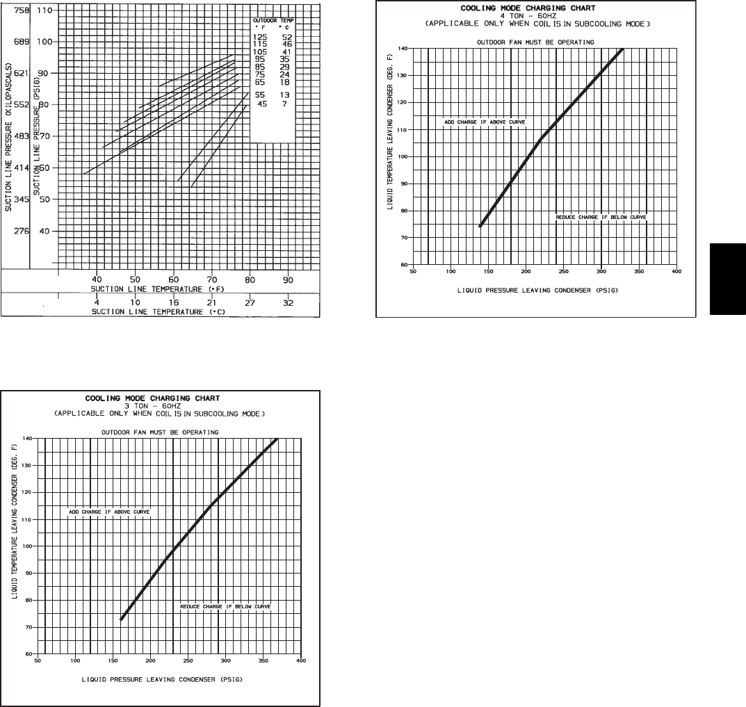
65
C06142
Fig. 61 --- Cooling Charging Chart,
Standard 50HJ007
C06143
Fig. 62 --- Cooling Charging Chart, 50HJ004 with
Optional Humidi--MiZer Adaptive Dehumidification System
C06144
Fig. 63 --- Cooling Charging Chart, 50HJ005 with
Optional Humidi--MiZer Adaptive Dehumidification System
NOTE: When using the charging charts, it is important that only
the subcooling/reheat dehumidification coil liquid line solenoid
valve be energized. The subcooling/reheat dehumidification coil
liquid line solenoid valve MUST be energized to use the charging
charts and the outdoor motor speed controller jumpered to run the
fanatfullspeed.
The charts reference a liquid pressure (psig) and temperature at a
point between the condenser coil and the subcooling/reheat
dehumidification coil. A tap is provided on the unit to measure
liquid pressure entering the subcooling/reheat dehumidification
coil.
IMPORTANT: The subcooling mode charging charts (Fig.
62--65) are to be used ONLY with units having the
Humidi--MiZer adaptive dehumidification system. DO NOT use
standard charge (Fig. 58--61) for units with Humidi-- MiZer
system, and DO NOT use Fig. 62--65 for standard units.
50HE,HJ
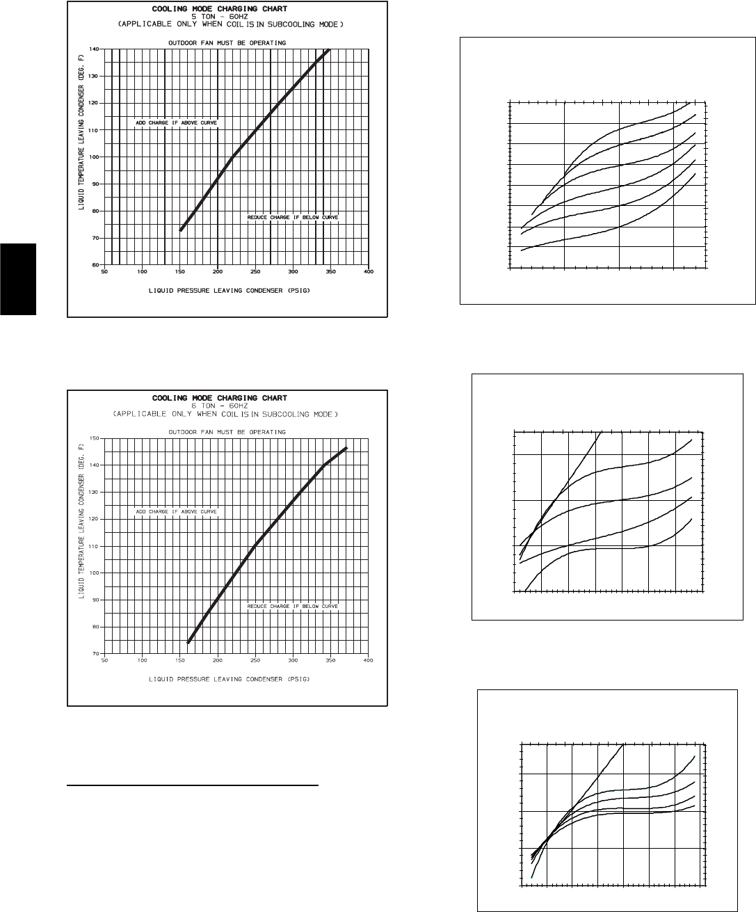
66
C06145
Fig. 64 --- Cooling Charging Chart, 50HJ005 with
Optional Humidi--MiZer Adaptive Dehumidification System
C06146
Fig. 65 --- Cooling Charging Chart, 50HJ007 with
Optional Humidi--MiZer Adaptive Dehumidification System
To Use Cooling Charging Chart, Standard Unit
Take the outdoor ambient temperature and read the suction
pressure gage. Refer to charts to determine what suction
temperature should be. If suction temperature is high, add
refrigerant. If suction temperature is low, carefully recover some
of the charge. Recheck the suction pressure as charge is adjusted.
Example (Fig. 57):
Outdoor Temperature 75F.........................
Suction Pressure 70 psig...........................
Suction Temperature should be 48F..................
(Suction temperature may vary 5F.)
If a charging device is used, temperature and pressure readings
must be accomplished using the charging charts.
50HE -- 2 TON CHARGING CHART
65.0
70.0
75.0
80.0
85.0
90.0
95.0
100.0
105.0
42 52 62 72
SuctionLineTemp(degF)
Suction Line Pressure (psig)
448.0
498.0
548.0
598.0
648.0
698.0
5.5 10.5 15.5 20.5 25.5
Suction Line Temperature (deg C)
Suction Line Pressure (kpa)
FC
125 52
115 4 6
105 41
95 35
85 29
75 24
C06148
Fig. 66 --- Cooling Charging Chart,
Standard 50HE003
50HE -- 3 TON CHARGING CHART
65.0
75.0
85.0
95.0
43 48 53 58 63 68 73 78
SuctionLineTemp(degF)
Suction Line Pressure (psig)
448.2
498.2
548.2
598.2
648.2
6.1 11.1 16.1 21.1
Suction Line Temperature (deg C)
Suction Line Pressure (kpa)
FC
115 4 6
105 41
95 35
85 29
75 24
C06149
Fig. 67 --- Cooling Charging Chart,
Standard 50HE004
50HE -- 4 TON CHARGING CHART
67.0
77.0
87.0
97.0
42 47 52 57 62 67 72 77
SuctionLineTemp(degF)
Suction Line Pressure (psig)
492.0
542.0
592.0
642.0
692.0
5.6 10.6 15.6 20.6 25.6
Suction Line Temperature (deg C)
Suction Line Pressure (kpa)
FC
115 46
105 41
95 35
85 29
75 24
C06150
Fig. 68 --- Cooling Charging Chart,
Standard 50HE005
50HE,HJ
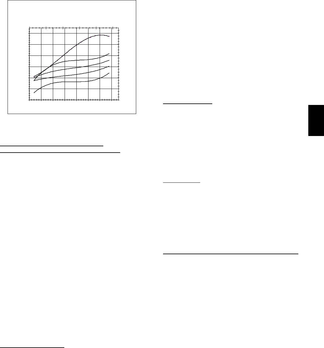
67
50HE -- 5 TON CHARGING CHART
55.0
65.0
75.0
85.0
95.0
105.0
115.0
42 47 52 57 62 67 72 77
SuctionLineTemp(degF)
Suction Line Pressure (psig)
310.0
410.0
510.0
610.0
710.0
810.0
0.0 5.0 10.0 15.0 20.0 25.0
Suction Line Temperature (deg C)
Suction Line Pressure (kpa)
FC
115 4 6
105 41
95 35
85 29
75 24
C06151
Fig. 69 --- Cooling Charging Chart,
Standard 50HE006
To Use Cooling Charging Charts, Units With
Humidi--MizerAdaptive Dehumidification System
Refer to charts (Fig. 62-65) to determine the proper leaving
condenser pressure and temperature.
Example (Fig. 62):
Leaving Condenser Pressure 250 psig.................
Leaving Condenser Temperature 105_F...............
NOTE: When using the charging charts, it is important that only
the subcooling/reheat dehumidification coil liquid line solenoid
valve be energized. The subcooling/reheat dehumidification coil
liquid line solenoid valve MUST be energized to use the charging
charts and the outdoor motor speed controller jumpered to run the
fanatfullspeed.
IMPORTANT: Refer to Troubleshooting Tables for additional
information.
Step 6 —Replacement Parts
A complete list of replacement parts may be obtained from any
Carrier distributor upon request.
TROUBLESHOOTING
Step 1 —Unit Troubleshooting
Refer to Tables 34-38 for unit troubleshooting details.
Step 2 —Economi$er IV Troubleshooting
See Table 39 for EconoMi$er IV logic.
A functional view of the EconoMi$er IV is shown in Fig. 67.
Typical settings, sensor ranges, and jumper positions are also
shown. An EconoMi$er IV simulator program is available from
Carrier to help with EconoMi$er IV training and
troubleshooting.
Economi$er IV Preparation
This procedure is used to prepare the EconoMi$er IV for
troubleshooting. No troubleshooting or testing is done by
performing the following procedure.
NOTE: This procedure requires a 9-v battery, 1.2 kilo-ohm
resistor, and a 5.6 kilo-ohm resistor which are not supplied with
the EconoMi$er IV.
IMPORTANT: Be sure to record the positions of all
potentiometers before starting troubleshooting.
1. Disconnect power at TR and TR1. All LEDs should be
off. Exhaust fan contacts should be open.
2. Disconnect device at P and P1.
3. Jumper P to P1.
4. Disconnect wires at T and T1. Place 5.6 kilo-ohm resistor
across T and T1.
5. Jumper TR to 1.
6. Jumper TR to N.
7. If connected, remove sensor from terminals SOand +.
Connect 1.2 kilo-ohm 4074EJM checkout resistor across
terminals SOand +.
8. Put 620-ohm resistor across terminals SRand +.
9. Set minimum position, DCV set point, and exhaust
potentiometers fully CCW (counterclockwise).
10. Set DCV maximum position potentiometer fully CW
(clockwise).
11. Set enthalpy potentiometer to D.
12. Apply power (24 vac) to terminals TR and TR1.
Differential Enthalpy
To check differential enthalpy:
1. Make sure EconoMi$er IV preparation procedure has been
performed.
2. Place 620-ohm resistor across SOand +.
3. Place 1.2 kilo-ohm resistor across SRand +. The Free
Cool LED should be lit.
4. Remove 620-ohm resistor across SOand +. The Free Cool
LED should turn off.
5. Return EconoMi$er IV settings and wiring to normal
after completing troubleshooting.
Single Enthalpy
To check single enthalpy:
1. Make sure EconoMi$er IV preparation procedure has been
performed.
2. Set the enthalpy potentiometer to A (fully CCW). The
Free Cool LED should be lit.
3. Set the enthalpy potentiometer to D (fully CW). The Free
Cool LED should turn off.
4. Return EconoMi$er IV settings and wiring to normal
after completing troubleshooting.
DCV (Demand Controlled Ventilation) and Power Exhaust
To check DCV and Power Exhaust:
1. Make sure EconoMi$er IV preparation procedure has been
performed.
2. Ensure terminals AQ and AQ1 are open. The LED for
both DCV and Exhaust should be off. The actuator should
be fully closed.
3. Connect a 9-v battery to AQ (positive node) and AQ1
(negative node). The LED for both DCV and Exhaust
should turn on. The actuator should drive to between 90
and 95% open.
4. Turn the Exhaust potentiometer CW until the Exhaust
LED turns off. The LED should turn off when the
potentiometer is approximately 90%. The actuator should
remain in position.
5. Turn the DCV set point potentiometer CW until the DCV
LED turns off. The DCV LED should turn off when the
potentiometer is approximately 9 v. The actuator should
drive fully closed.
6. Turn the DCV and Exhaust potentiometers CCW until the
Exhaust LED turns on. The exhaust contacts will close 30
to 120 seconds after the Exhaust LED turns on.
7. Return EconoMi$er IV settings and wiring to normal
after completing troubleshooting.
50HE,HJ

68
DCV Minimum and Maximum Position
To check the DCV minimum and maximum position:
1. Make sure EconoMi$er IV preparation procedure has been
performed.
2. Connect a 9-v battery to AQ (positive node) and AQ1
(negative node). The DCV LED should turn on. The
actuator should drive to between 90 and 95% open.
3. Turn the DCV Maximum Position potentiometer to
midpoint. The actuator should drive to between 20 and
80% open.
4. Turn the DCV Maximum Position potentiometer to fully
CCW. The actuator should drive fully closed.
5. Turn the Minimum Position potentiometer to midpoint.
The actuator should drive to between 20 and 80% open.
6. Turn the Minimum Position Potentiometer fully CW. The
actuator should drive fully open.
7. Remove the jumper from TR and N. The actuator should
drive fully closed.
8. Return EconoMi$er IV settings and wiring to normal
after completing troubleshooting.
Supply--Air Input
To check supply-air input:
1. Make sure EconoMi$er IV preparation procedure has been
performed.
2. Set the Enthalpy potentiometer to A. The Free Cool LED
turns on. The actuator should drive to between 20 and
80% open.
3. Remove the 5.6 kilo-ohm resistor and jumper T to T1. The
actuator should drive fully open.
4. Remove the jumper across T and T1. The actuator should
drive fully closed.
5. Return EconoMi$er IV settings and wiring to normal
after completing troubleshooting.
Economi$er IV Troubleshooting Completion
This procedure is used to return the EconoMi$er IV to operation.
No troubleshooting or testing is done by performing the
following procedure.
1. Disconnect power at TR and TR1.
2. Set enthalpy potentiometer to previous setting.
3. Set DCV maximum position potentiometer to previous
setting.
4. Set minimum position, DCV set point, and exhaust
potentiometers to previous settings.
5. Remove 620-ohm resistor from terminals SRand +.
6. Remove 1.2 kilo-ohm checkout resistor from terminals SO
and +. If used, reconnect sensor from terminals SOand +.
7. Remove jumper from TR to N.
8. Remove jumper from TR to 1.
9. Remove 5.6 kilo-ohm resistor from T and T1. Reconnect
wires at T and T1.
10. Remove jumper from P to P1. Reconnect device at P and
P1.
11. Apply power (24 vac) to terminals TR and TR1.
50HE,HJ

69
Table 36—Cooling Service Analysis
PROBLEM CAUSE REMEDY
Compressor and Condenser Fan
Will Not Start.
Power failure. Call power company.
Fuse blown or circuit breaker tripped. Replace fuse or reset circuit breaker.
Defective thermostat, contactor, transformer, or
control relay.
Replace component.
Insufficient line voltage. Determine cause and correct.
Incorrect or faulty wiring. Check wiring diagram and rewire correctly.
Thermostat setting too high. Lower thermostat setting below room temperature.
Compressor Will Not Start
But Condenser Fan Runs.
Faulty wiring or loose connections in compres-
sor circuit.
Check wiring and repair or replace.
Compressor motor burned out, seized, or in-
ternal overload open.
Determine cause. Replace compressor.
Defective run/start capacitor, overload, start
relay.
Determine cause and replace.
One leg of 3-phase power dead. Replace fuse or reset circuit breaker. Determine
cause.
CompressorCycles(OtherThan
Normally Satisfying Thermostat).
Refrigerant overcharge or undercharge. Recover refrigerant, evacuate system, and recharge
to nameplate.
Defective compressor. Replace and determine cause.
Insufficient line voltage. Determine cause and correct.
Blocked condenser. Determine cause and correct.
Defective run/start capacitor, overload, or start
relay.
Determine cause and replace.
Defective thermostat. Replace thermostat.
Faulty condenser-fan motor or capacitor. Replace.
Restriction in refrigerant system. Locate restriction and remove.
Compressor Operates Continuously. Dirty air filter. Replace filter.
Unit undersized for load. Decrease load or increase unit size.
Thermostat set too low. Reset thermostat.
Low refrigerant charge. Locate leak, repair, and recharge.
Leaking valves in compressor. Replace compressor.
Air in system. Recover refrigerant, evacuate system, and recharge.
Condenser coil dirty or restricted. Clean coil or remove restriction.
Excessive Head Pressure. Dirty air filter. Replace filter.
Dirty condenser coil. Clean coil.
Refrigerant overcharged. Recover excess refrigerant.
Air in system. Recover refrigerant, evacuate system, and recharge.
Condenser air restricted or air short-cycling. Determine cause and correct.
Head Pressure Too Low. Low refrigerant charge. Check for leaks, repair, and recharge.
Compressor valves leaking. Replace compressor.
Restrictioninliquidtube. Remove restriction.
Excessive Suction Pressure. High heat load. Check for source and eliminate.
Compressor valves leaking. Replace compressor.
Refrigerant overcharged. Recover excess refrigerant.
Suction Pressure Too Low. Dirty air filter. Replace filter.
Low refrigerant charge. Check for leaks, repair, and recharge.
Metering device or low side restricted. Remove source of restriction.
Insufficient evaporator airflow. Increase air quantity. Check filter and replace if neces-
sary.
Temperature too low in conditioned area. Reset thermostat.
Outdoor ambient below 25 F. Install low-ambient kit.
Evaporator Fan Will Not Shut Off. Time off delay not finished. Wait for 30-second off delay.
50HE,HJ
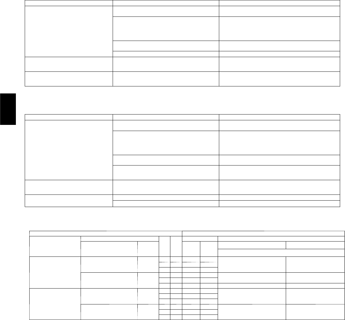
70
Table 37—Humidi-MiZerAdaptive Dehumidification System Subcooling Mode Service Analysis
PROBLEM CAUSE REMEDY
Subcooling Mode (Liquid Reheat)
Will Not Energize.
No power to control transformer from
evaporator-fan motor.
Check power source and evaporator-fan relay. Ensure all
wire connections are tight.
No power from control transformer to liquid line
solenoid valve.
1. Fuse open; check fuse. Ensure continuity of wiring.
2. Low-pressure switch open. Cycle unit off and allow
low-pressure switch to reset. Replace switch if it will
not close.
3. Transformer bad; check transformer.
Liquid line solenoid valve will not operate. 1. Solenoid coil defective; replace.
2. Solenoid valve stuck open; replace.
Liquid line solenoid valve will not open. Valve is stuck closed; replace valve.
Low System Capacity. Low refrigerant charge or frosted evaporator coil. 1. Check charge amount. Charge per Fig. 59-62.
2. Evaporator coil frosted; check and replace low-pres-
sure switch if necessary.
Loss of Compressor Superheat
Conditions with Subcooling/Reheat
Dehumidification Coil Energized.
Thermostatic expansion valve (TXV). 1. Check TXV bulb mounting, and secure tightly to suc-
tion line.
2. Replace TXV if stuck open or closed.
Table 38—Humidi-MiZerAdaptive Dehumidification System Hot Gas Reheat Mode Service Analysis
PROBLEM CAUSE REMEDY
Reheat Mode Will Not Energize. No power to control transformer from
evaporator-fan motor.
Check power source and evaporator-fan relay. Ensure all
wire connections are tight.
No power from control transformer to hot gas
line solenoid valve
1. Fuse open; check fuse. Ensure continuity of wiring.
2. Low-pressure switch open. Cycle unit off and allow
low-pressure switch to reset. Replace switch if it will
not close.
3. Transformer bad; check transformer.
Hot gas line solenoid valve will not operate. 1. Solenoid coil defective; replace.
2. Solenoid valve stuck closed; replace.
Low refrigerant charge or frosted evaporator coil. 1. Check charge amount. Charge per Fig. 59-62.
2. Evaporator coil frosted; check and replace low-pres-
sure switch if necessary.
Loss of Compressor Superheat
Conditions with Subcooling/Reheat
Dehumidification Coil Energized.
Thermostatic expansion valve (TXV). 1. Check TXV bulb mounting, and secure tightly to suc-
tion line.
2. Replace TXV if stuck open or closed.
Excessive Superheat. Liquid line solenoid valve will not operate. Valve is stuck, replace valve.
Hot gas line solenoid valve will not close. Valve is stuck; replace valve.
Table 39—EconoMi$er IV Input/Output Logic
INPUTS OUTPUTS
Demand Control
Ventilation (DCV)
Enthalpy*
Y1 Y2
Compressor NTerminal†
Outdoor Return
Stage
1
Stage
2
Occupied Unoccupied
Damper
Below set
(DCV LED Off)
High
(Free Cooling LED Off)
Low On On On On Minimum position Closed
On Off On Off
Off Off Off Off
Low
(Free Cooling LED On)
High On On On Off Modulating** (between min.
position and full-open)
Modulating** (between
closed and full-open)
On Off Off Off
Off Off Off Off Minimum position Closed
Above set
(DCV LED On)
High
(Free Cooling LED Off)
Low On On On On Modulating†† (between min.
position and DCV maximum)
Modulating†† (between
closed and DCV
maximum)
On Off On Off
Off Off Off Off
Low
(Free Cooling LED On)
High On On On Off Modulating*** Modulating†††
On Off Off Off
Off Off Off Off
*For single enthalpy control, the module compares outdoor enthalpy to the ABCD set point.
†Power at N terminal determines Occupied/Unoccupied setting: 24 vac (Occupied), no power (Unoccupied).
**Modulation is based on the supply-air sensor signal.
††Modulation is based on the DCV signal.
***Modulation is based on the greater of DCV and supply-air sensor signals, between minimum position and either maximum position (DCV) or fully open (sup-
ply-air signal).
†††Modulation is based on the greater of DCV and supply-air sensor signals, between closed and either maximum position (DCV) or fully open (supply-airsig-
nal).
50HE,HJ
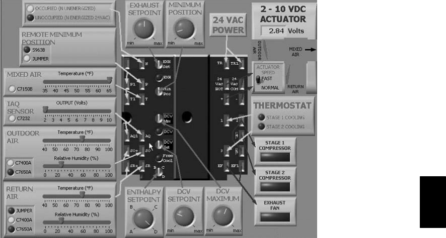
71
C06053
Fig. 70 --- EconoMi$er IV Functional View
50HE,HJ

72
START-UP CHECKLIST
(Remove and Store in Job File)
I. PRELIMINARY INFORMATION
MODEL NO.: SERIAL NO.:
DATE: TECHNICIAN:
II. PRE-START-UP (insert checkmark in box as each item is completed)
jVERIFY THAT JOBSITE VOLTAGE AGREES WITH VOLTAGE LISTED ON RATING PLATE
jVERIFY THAT ALL PACKAGING MATERIALS HAVE BEEN REMOVED FROM UNIT
jREMOVE ALL SHIPPING HOLDDOWN BOLTS AND BRACKETS PER INSTALLATION INSTRUCTIONS
jVERIFY THAT CONDENSATE CONNECTION IS INSTALLED PER INSTALLATION INSTRUCTIONS
jCHECK ALL ELECTRICAL CONNECTIONS AND TERMINALS FOR TIGHTNESS
jCHECK GAS PIPING FOR LEAKS
jCHECK THAT RETURN (INDOOR) AIR FILTERS ARE CLEAN AND IN PLACE
jVERIFY THAT UNIT INSTALLATION IS LEVEL
jCHECK FAN WHEELS AND PROPELLER FOR LOCATION IN HOUSING/ORIFICE AND SETSCREW
TIGHTNESS
jCHECK TO ENSURE THAT ELECTRICAL WIRING IS NOT IN CONTACT WITH REFRIGERANT LINES
OR SHARP METAL EDGES
jCHECK PULLEY ALIGNMENT AND BELT TENSION PER INSTALLATION INSTRUCTIONS
III. START-UP
ELECTRICAL
SUPPLY VOLTAGE L1-L2 L2-L3 L3-L1
COMPRESSOR AMPS L1 L2 L3
INDOOR-FAN AMPS L1 L2 L3
TEMPERATURES
OUTDOOR-AIR TEMPERATURE DB
RETURN-AIR TEMPERATURE DB WB
COOLING SUPPLY AIR DB WB
PRESSURES (Cooling Mode)
REFRIGERANT SUCTION PSIG F
REFRIGERANT DISCHARGE PSIG F
jVERIFY THAT 3-PHASE FAN MOTOR AND BLOWER ARE ROTATING IN CORRECT DIRECTION. IF THEY
ARE NOT ROTATING IN CORRECT DIRECTION, LOCKING COLLAR MUST BE RE--TIGHTENED AFTER
CORRECTING DIRECTION OF ROTATION
jVERIFY THAT 3-PHASE SCROLL COMPRESSOR IS ROTATING IN THE CORRECT DIRECTION
jVERIFY REFRIGERANT CHARGE USING CHARGING CHARTS
GENERAL
jSET ECONOMIZER MINIMUM VENT AND CHANGEOVER SETTINGS TO MATCH JOB REQUIREMENTS
(IF EQUIPPED)
Copyright 2006 Carrier Corp. S7310 W. Morris St. SIndianapolis, IN 46231
Manufacturer reserves the right to change, at any time, specifications and designs without notice and without obligations.
Catalog No:50H--1SI
Replaces:50HJ--31SI
Printed in U.S.A. Edition Date:09/06
50HE,HJ
